TOPIC 3 - fkm.utm.mymohsin/skmm2433/notes/02.gas.power.cycles/To… · Mohd Kamal Ariffin, FKM,...
52
GAS TURBINE CYCLES Mohd Kamal Ariffin, FKM, UTM, 2013 TOPIC 3
-
Upload
hoangtuong -
Category
Documents
-
view
221 -
download
1
Transcript of TOPIC 3 - fkm.utm.mymohsin/skmm2433/notes/02.gas.power.cycles/To… · Mohd Kamal Ariffin, FKM,...
GAS TURBINE
CYCLES
Mohd Kamal Ariffin, FKM, UTM, 2013
TOPIC 3
INTRODUCTION
Mohd Kamal Ariffin, FKM, UTM, 20132
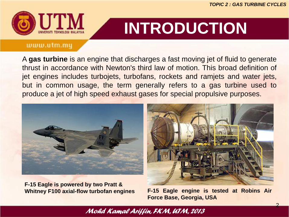
A gas turbine is an engine that discharges a fast moving jet of fluid to generate
thrust in accordance with Newton's third law of motion. This broad definition of
jet engines includes turbojets, turbofans, rockets and ramjets and water jets,
but in common usage, the term generally refers to a gas turbine used to
produce a jet of high speed exhaust gases for special propulsive purposes.
F-15 Eagle engine is tested at Robins Air
Force Base, Georgia, USA
F-15 Eagle is powered by two Pratt &
Whitney F100 axial-flow turbofan engines
TOPIC 2 : GAS TURBINE CYCLES
TYPES OF GAS TURBINE
Mohd Kamal Ariffin, FKM, UTM, 20133
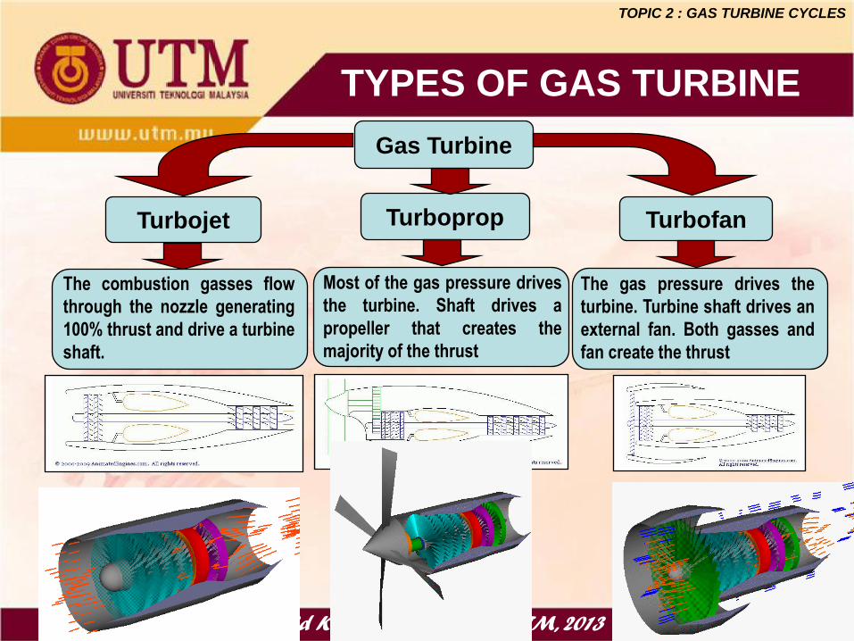
Gas Turbine
TurbopropTurbojet Turbofan
The combustion gasses flow
through the nozzle generating
100% thrust and drive a turbine
shaft.
Most of the gas pressure drives
the turbine. Shaft drives a
propeller that creates the
majority of the thrust
The gas pressure drives the
turbine. Turbine shaft drives an
external fan. Both gasses and
fan create the thrust
TOPIC 2 : GAS TURBINE CYCLES
INTRODUCTION
Mohd Kamal Ariffin, FKM, UTM, 20134
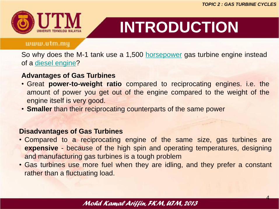
Disadvantages of Gas Turbines
• Compared to a reciprocating engine of the same size, gas turbines are
expensive - because of the high spin and operating temperatures, designing
and manufacturing gas turbines is a tough problem
• Gas turbines use more fuel when they are idling, and they prefer a constant
rather than a fluctuating load.
Advantages of Gas Turbines
• Great power-to-weight ratio compared to reciprocating engines. i.e. the
amount of power you get out of the engine compared to the weight of the
engine itself is very good.
• Smaller than their reciprocating counterparts of the same power
So why does the M-1 tank use a 1,500 horsepower gas turbine engine instead
of a diesel engine?
TOPIC 2 : GAS TURBINE CYCLES

Mohd Kamal Ariffin, FKM, UTM, 20105
• Aircraft propulsion system
• Electric power generation
• Marine vehicle propulsion
• Combined-cycle power plant
(with steam power plant)
• Tanks
THE USE OF GAS TURBINE
MiG-29
F-15 Eagle
Naval Vessel - Iroquois-class destroyers
TOPIC 2 : GAS TURBINE CYCLES
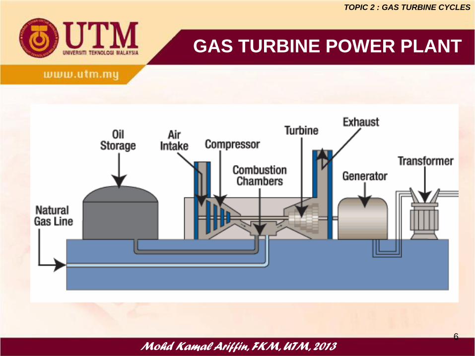
GAS TURBINE POWER PLANT
Mohd Kamal Ariffin, FKM, UTM, 20136
TOPIC 2 : GAS TURBINE CYCLES
Mohd Kamal Ariffin, FKM, UTM, 20137
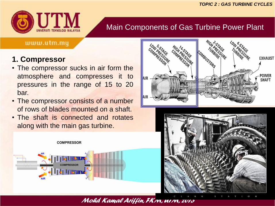
Main Components of Gas Turbine Power Plant
1. Compressor• The compressor sucks in air form the
atmosphere and compresses it to
pressures in the range of 15 to 20
bar.
• The compressor consists of a number
of rows of blades mounted on a shaft.
• The shaft is connected and rotates
along with the main gas turbine.
TOPIC 2 : GAS TURBINE CYCLES
Mohd Kamal Ariffin, FKM, UTM, 20138
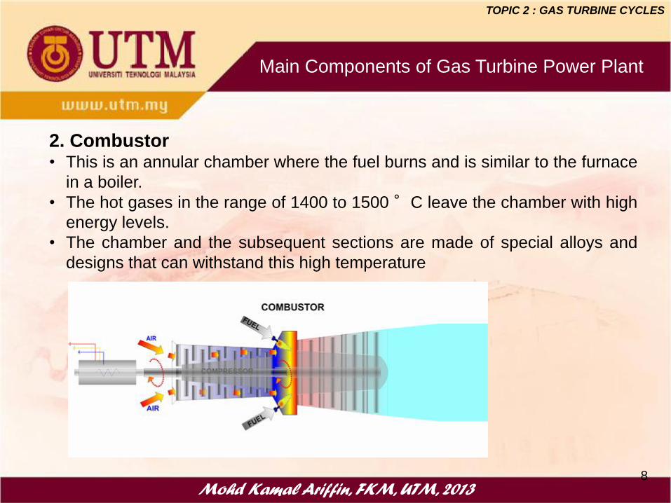
Main Components of Gas Turbine Power Plant
2. Combustor• This is an annular chamber where the fuel burns and is similar to the furnace
in a boiler.
• The hot gases in the range of 1400 to 1500°C leave the chamber with high
energy levels.
• The chamber and the subsequent sections are made of special alloys and
designs that can withstand this high temperature
TOPIC 2 : GAS TURBINE CYCLES
Mohd Kamal Ariffin, FKM, UTM, 20139
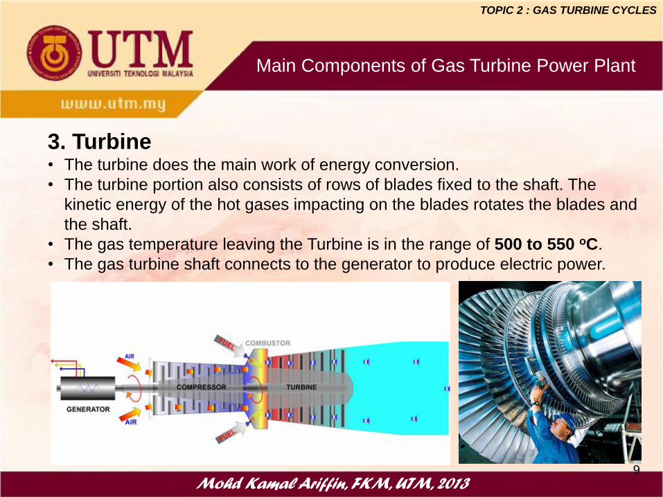
Main Components of Gas Turbine Power Plant
3. Turbine• The turbine does the main work of energy conversion.
• The turbine portion also consists of rows of blades fixed to the shaft. The
kinetic energy of the hot gases impacting on the blades rotates the blades and
the shaft.
• The gas temperature leaving the Turbine is in the range of 500 to 550 oC.
• The gas turbine shaft connects to the generator to produce electric power.
TOPIC 2 : GAS TURBINE CYCLES

Mohd Kamal Ariffin, FKM, UTM, 201310
Auxiliary Components of Gas Turbine Power Plant
The Fuel system prepares a clean fuel for burning in the combustor. Gas
Turbines normally burn Natural gas but can also fire diesel or distillate fuels
Starting system provides
the initial momentum for
the Gas Turbine to reach
the operating speed.
This is similar to the
starter motor of your car
Air Intake System
provides clean air into
the compressor
Exhaust system
discharges the hot gases
to a level which is safe
for the people and the
environment
TOPIC 2 : GAS TURBINE CYCLES
The Practical Gas Turbine Cycle
Mohd Kamal Ariffin, FKM, UTM, 201311
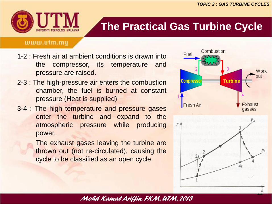
1-2 : Fresh air at ambient conditions is drawn into
the compressor, its temperature and
pressure are raised.
2-3 : The high-pressure air enters the combustion
chamber, the fuel is burned at constant
pressure (Heat is supplied)
3-4 : The high temperature and pressure gases
enter the turbine and expand to the
atmospheric pressure while producing
power.
The exhaust gases leaving the turbine are
thrown out (not re-circulated), causing the
cycle to be classified as an open cycle.
TOPIC 2 : GAS TURBINE CYCLES
Mohd Kamal Ariffin, FKM, UTM, 2013
The Practical Gas Turbine Cycle
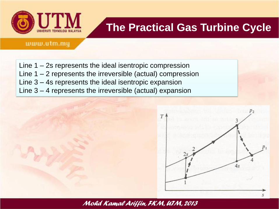
Line 1 – 2s represents the ideal isentropic compression
Line 1 – 2 represents the irreversible (actual) compression
Line 3 – 4s represents the ideal isentropic expansion
Line 3 – 4 represents the irreversible (actual) expansion

Mohd Kamal Ariffin, FKM, UTM, 2013
The Practical Gas Turbine Cycle
1
2 2
1 1
T p
T p
p-v-T relationships for isentropic process:1
2 1
1 2
T v
T v
2 1
1 2
p v
p v
1. pV = mRT (kJ) or pv = RT (kJ/kg) where R is specific gas constant
Ideal gas equations :
1 1 2 2
1 2
pV p V
T T (p in kPa, V in m3 and T in K)
2 1 2 1ph h c T T
Where cp is specific heat at constant pressure and cv is specific heat
at constant volume
Where is specific heat ration, p
v
c
c
p vc c R
2.
3.
4.

Mohd Kamal Ariffin, FKM, UTM, 2013
The Practical Gas Turbine Cycle
12 2 1 2 1Work input = wc pa
w h h c T T
23 3 2 3 21Heat supplied = qcc pg
q h h c T T
34 3 4 3 4Work output = wT pg
w h h c T T
34 12
3 4 2 1
Net Work output = w
=
T C
pg pa
w w w
c T T c T T
3 4 2 1
3 2
Net work outputThermal Efficiency,
Heat supplied
pg pa
th
pg
c T T c T T
c T T
Energy Analysis

Mohd Kamal Ariffin, FKM, UTM, 2013
The Practical Gas Turbine Cycle
2 1 2 112
12 2 1 2 1
Compressor Isentropic Efficiency, =pa s ss
C
pa
c T T T Tw
w c T T T T
Energy Analysis
3 4 3 434
34 3 4 3 4
Turbine Isentropic Efficiency, =pg
T
s pg s s
c T T T Tw
w c T T T T
3 4 2 1
3 4
Work ratio,
Net work outputr
Gross work output
=
netw
T
T C
T
pg pa
pg
w
w
w w
w
c T T c T T
c T T

Mohd Kamal Ariffin, FKM, UTM, 2013
Example 9.1
A gas turbine unit has a pressure ratio of 10/1 and a maximum cycle
temperature of 700 oC. The isentropic efficiencies of the compressor and turbine
are 0.82 and 0.85 respectively. Calculate the power output of an electric
generator geared to the turbine when the air enters the compressor at 15 oC at
the rate of 15 kg/s. Take cp = 1.005 kJ/kgK and = 1.4 for the compression
process and cp = 1.11 kJ/kgK and = 1.333 for the expansion process.
Solution :
In order to evaluate the net work output, it is necessary to determine theT2, T2S
and T4.

Mohd Kamal Ariffin, FKM, UTM, 2013
Example 9.1
A gas turbine unit has a pressure ratio of 10/1 and a maximum cycle temperature of 700oC. The isentropic efficiencies of the compressor and turbine are 0.82 and 0.85
respectively. Calculate the power output of an electric generator geared to the turbine
when the air enters the compressor at 15 oC at the rate of 15 kg/s. Take cp = 1.005 kJ/kgK
and = 1.4 for the compression process and cp = 1.11 kJ/kgK and = 1.333 for the
expansion process.

Mohd Kamal Ariffin, FKM, UTM, 2013
Example 9.2
Calculate the cycle efficiency and the work ratio of the
plant in Example 9.1, assuming that cp for the combustion
process is 1.11 kJ/kgK.
Mohd Kamal Ariffin, FKM, UTM, 201019
USE OF POWER TURBINE
TOPIC 3 : BRAYTON CYCLE – THE IDEAL CYCLE FOR GAS TURBINE
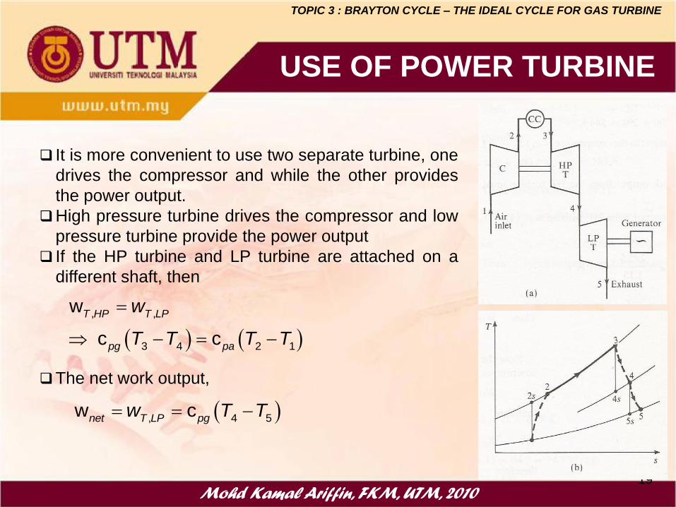
It is more convenient to use two separate turbine, one
drives the compressor and while the other provides
the power output.
High pressure turbine drives the compressor and low
pressure turbine provide the power output
If the HP turbine and LP turbine are attached on a
different shaft, then
The net work output,
, ,
3 4 2 1
w
c c
T HP T LP
pg pa
w
T T T T
, 4 5w cnet T LP pg
w T T
Mohd Kamal Ariffin, FKM, UTM, 201020
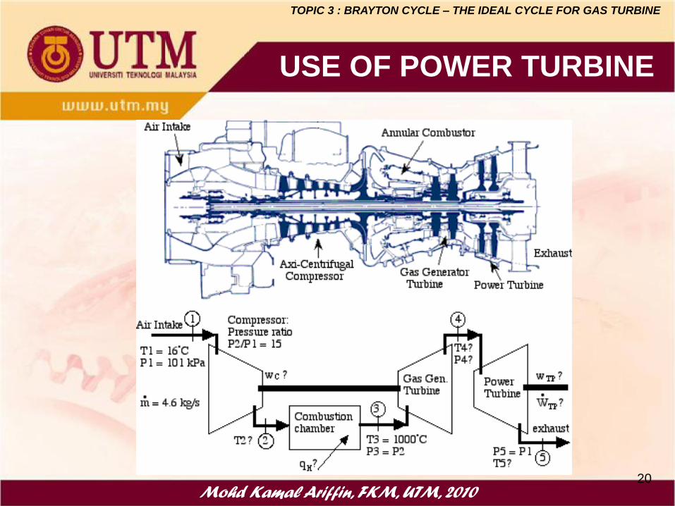
USE OF POWER TURBINE
TOPIC 3 : BRAYTON CYCLE – THE IDEAL CYCLE FOR GAS TURBINE
Mohd Kamal Ariffin, FKM, UTM, 2013
Example 9.3
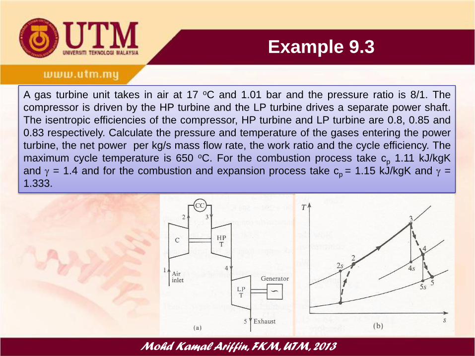
A gas turbine unit takes in air at 17 oC and 1.01 bar and the pressure ratio is 8/1. The
compressor is driven by the HP turbine and the LP turbine drives a separate power shaft.
The isentropic efficiencies of the compressor, HP turbine and LP turbine are 0.8, 0.85 and
0.83 respectively. Calculate the pressure and temperature of the gases entering the power
turbine, the net power per kg/s mass flow rate, the work ratio and the cycle efficiency. The
maximum cycle temperature is 650 oC. For the combustion process take cp 1.11 kJ/kgK
and = 1.4 and for the combustion and expansion process take cp = 1.15 kJ/kgK and =
1.333.

Mohd Kamal Ariffin, FKM, UTM, 2013
Example 9.3
A gas turbine unit takes in air at 17 oC and 1.01 bar and the pressure ratio is 8/1. The
compressor is driven by the HP turbine and the LP turbine drives a separate power shaft.
The isentropic efficiencies of the compressor, HP turbine and LP turbine are 0.8, 0.85
and 0.83 respectively. Calculate the pressure and temperature of the gases entering the
power turbine, the net power per kg/s mass flow rate, the work ratio and the cycle
efficiency. The maximum cycle temperature is 650 oC. For the combustion process take
cp 1.11 kJ/kgK and = 1.4 and for the combustion and expansion process take cp = 1.15
kJ/kgK and = 1.333.
Mohd Kamal Ariffin, FKM, UTM, 201023
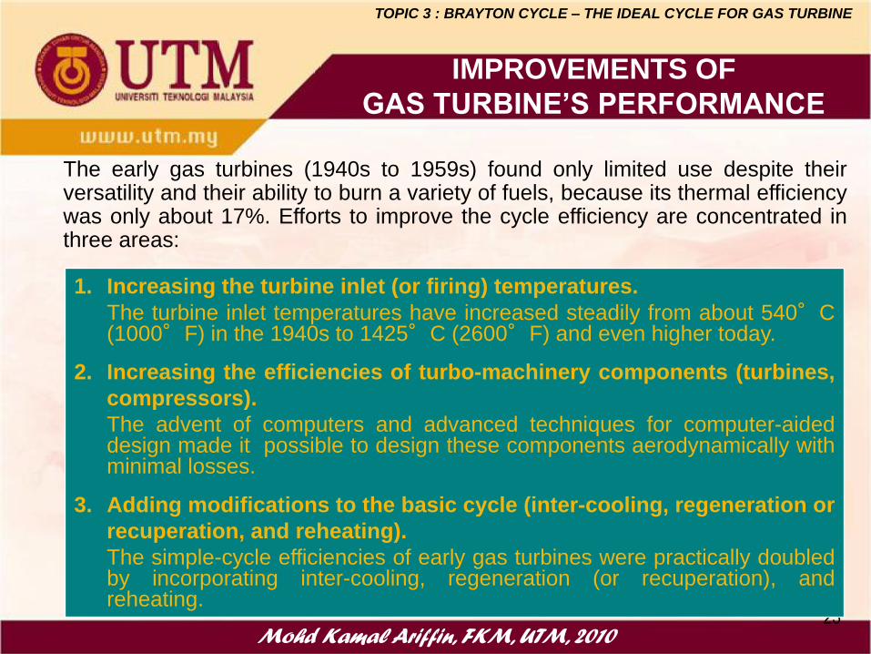
The early gas turbines (1940s to 1959s) found only limited use despite theirversatility and their ability to burn a variety of fuels, because its thermal efficiencywas only about 17%. Efforts to improve the cycle efficiency are concentrated inthree areas:
1. Increasing the turbine inlet (or firing) temperatures.
The turbine inlet temperatures have increased steadily from about 540°C(1000°F) in the 1940s to 1425°C (2600°F) and even higher today.
2. Increasing the efficiencies of turbo-machinery components (turbines,
compressors).
The advent of computers and advanced techniques for computer-aideddesign made it possible to design these components aerodynamically withminimal losses.
3. Adding modifications to the basic cycle (inter-cooling, regeneration or
recuperation, and reheating).
The simple-cycle efficiencies of early gas turbines were practically doubledby incorporating inter-cooling, regeneration (or recuperation), andreheating.
IMPROVEMENTS OF
GAS TURBINE’S PERFORMANCE
TOPIC 3 : BRAYTON CYCLE – THE IDEAL CYCLE FOR GAS TURBINE

Mohd Kamal Ariffin, FKM, UTM, 201024
TWO STAGE COMPRESSION WITH
INTERCOOLING
The compressor work input can be reduced by
carrying out the compression process in stages
and with an intercooler between the stage, thus
will increase the net work output and thermal
efficiency.
Process 1BD is isothermal compression, with a
minimum work required
Process 1AC is polytropic process for single
stage compressor
Process 1ABD is polytropic process for two
stage compressor with intercooling
The shaded area is the work saved as a result of
intercooling process.
TOPIC 3 : BRAYTON CYCLE – THE IDEAL CYCLE FOR GAS TURBINE

Mohd Kamal Ariffin, FKM, UTM, 201025
TWO STAGE COMPRESSION WITH
INTERCOOLING
Processes 1-2-3-4 with intercooling between LP and
HP compressor and process 1-A is a single stage
compression without intercooling.
Work input with intercooling
Work input with intercooling
Where
Minimum work input requirement :
a) Equal pressure ratio for each stage of compressor
P2/P1 = P4/P3
b) Complete intercooling (T1 =T3)
TOPIC 3 : BRAYTON CYCLE – THE IDEAL CYCLE FOR GAS TURBINE
2 1 4 3in pa paw c T T c T T
1in pa Aw c T T
2 1 4 3 1pa pa pa Ac T T c T T c T T

Mohd Kamal Ariffin, FKM, UTM, 201026
TWO STAGE COMPRESSION WITH
INTERCOOLING
TOPIC 3 : BRAYTON CYCLE – THE IDEAL CYCLE FOR GAS TURBINE
5 6out T pgw w c T T
, , 2 1 4 3in C LP C HP pa paw w w c T T c T T
, ,
5 6 2 1 4 3 = c
net T C LP C HP
pg pa
w w w w
T T c T T T T
sup 45 5 4ply pgq q c T T
56 12 34
sup 45
Thermal Efficiency, netth
ply
w w ww
q q
Mohd Kamal Ariffin, FKM, UTM, 201027
EXAMPLE
TOPIC 3 : BRAYTON CYCLE – THE IDEAL CYCLE FOR GAS TURBINE
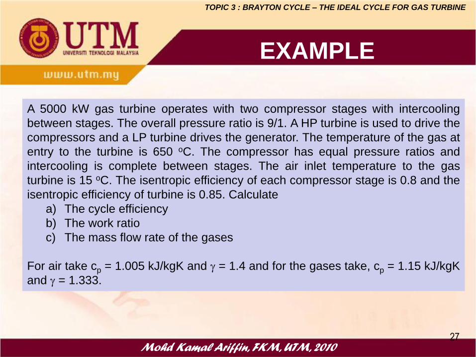
A 5000 kW gas turbine operates with two compressor stages with intercooling
between stages. The overall pressure ratio is 9/1. A HP turbine is used to drive the
compressors and a LP turbine drives the generator. The temperature of the gas at
entry to the turbine is 650 oC. The compressor has equal pressure ratios and
intercooling is complete between stages. The air inlet temperature to the gas
turbine is 15 oC. The isentropic efficiency of each compressor stage is 0.8 and the
isentropic efficiency of turbine is 0.85. Calculate
a) The cycle efficiency
b) The work ratio
c) The mass flow rate of the gases
For air take cp = 1.005 kJ/kgK and = 1.4 and for the gases take, cp = 1.15 kJ/kgK
and = 1.333.

Mohd Kamal Ariffin, FKM, UTM, 201028
EXAMPLE
TOPIC 3 : BRAYTON CYCLE – THE IDEAL CYCLE FOR GAS TURBINE
A 5000 kW gas turbine operates with two compressor stages with intercooling between stages. The overall pressure ratio is 9/1. A HP turbine is
used to drive the compressors and a LP turbine drives the generator. The temperature of the gas at entry to the turbine is 650 oC. The compressor
has equal pressure ratios and intercooling is complete between stages. The air inlet temperature to the gas turbine is 15 oC. The isentropic efficiency
of each compressor stage is 0.8 and the isentropic efficiency of turbine is 0.85. Calculate the cycle efficiency, the work ratio and the mass flow rate
of the gases. For air take cpa = 1.005 kJ/kgK and a = 1.4 and for the gases take, cpg = 1.15 kJ/kgK and g = 1.333.
Solution :
Mohd Kamal Ariffin, FKM, UTM, 201029
REHEAT CYCLE
TOPIC 3 : BRAYTON CYCLE – THE IDEAL CYCLE FOR GAS TURBINE
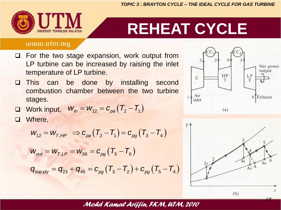
For the two stage expansion, work output from
LP turbine can be increased by raising the inlet
temperature of LP turbine.
This can be done by installing second
combustion chamber between the two turbine
stages.
Work input,
Where,
12 2 1in paw w c T T
sup 23 45 3 2 5 4ply pg pgq q q c T T c T T
12 , 2 1 3 4 T HP pa pg
w w c T T c T T
, 56 5 6out T LP pgw w w c T T

Mohd Kamal Ariffin, FKM, UTM, 201030
EXAMPLE 9.4 Pg. 296
TOPIC 3 : BRAYTON CYCLE – THE IDEAL CYCLE FOR GAS TURBINE
A 5000 kW gas turbine operates with two compressor stages with intercooling
between stages. The overall pressure ratio is 9/1. A HP turbine is used to drive the
compressors and a LP turbine drives the generator. The temperature of the gas at
entry to the HP turbine is 650 oC and the gases are reheated to 650 oC after
expansion in the first turbine. The compressor has equal pressure ratios and
intercooling is complete between stages. The air inlet temperature to the gas
turbine is 15 oC. The isentropic efficiency of each compressor stage is 0.8 and the
isentropic efficiency of each turbine is 0.85. Calculate
1. The cycle efficiency
2. The work ratio
3. The mass flow rate of the gases
For air take cp = 1.005 kJ/kgK and = 1.4 and for the gases take, cp = 1.15 kJ/kgK
and = 1.333.

Mohd Kamal Ariffin, FKM, UTM, 201031
TOPIC 3 : BRAYTON CYCLE – THE IDEAL CYCLE FOR GAS TURBINE
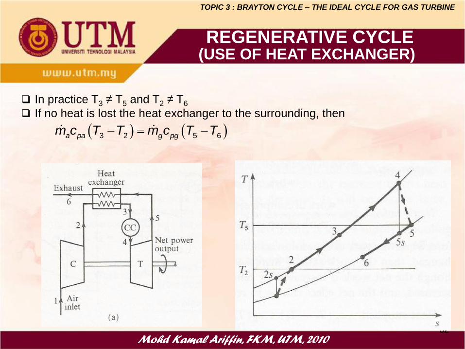
The exhaust gases leaving the turbine are
still at high temperature (high energy) –
waste of energy.
Some of this energy can be recovered by
passing the gasses from the turbine
through a heat exchanger to heat the air
leaving the compressor.
Process 2-3 : Compressed air from the
compressor is heated by exhaust gases
from the turbine from T2 to T3.
Process 5-6 : Exhaust gases will be cooled
from T5 to T6 after giving up the heat.
For an ideal case : T3 = T5 and T2 = T6
REGENERATIVE CYCLE(USE OF HEAT EXCHANGER)
Mohd Kamal Ariffin, FKM, UTM, 201032
TOPIC 3 : BRAYTON CYCLE – THE IDEAL CYCLE FOR GAS TURBINE
In practice T3 ≠ T5 and T2 ≠ T6
If no heat is lost the heat exchanger to the surrounding, then
REGENERATIVE CYCLE(USE OF HEAT EXCHANGER)
3 2 5 6a pa g pgm c T T m c T T

Mohd Kamal Ariffin, FKM, UTM, 201033
TOPIC 3 : BRAYTON CYCLE – THE IDEAL CYCLE FOR GAS TURBINE
Actual and maximum heat can be transferred to air can
be expressed as
Heat exchanger effectiveness is used to allow for the
temperature difference necessary for the transfer of heat
and define as,
Some times is called thermal ratio
REGENERATIVE CYCLE(USE OF HEAT EXCHANGER)
3 2 3 2
3' 2 5 2
Heat received by the air, =
maximum possible heat could be transferred
=a pa
a pa
Effectiveness
m c T T T T
m c T T T T
●3’
3 2 3 2
max 3' 2 3' 2
5 2 5 3'
Q
actual a pa
a pa
a pa
Q h h m c T T
h h m c T T
m c T T T T
Mohd Kamal Ariffin, FKM, UTM, 201034
TOPIC 3 : BRAYTON CYCLE – THE IDEAL CYCLE FOR GAS TURBINE
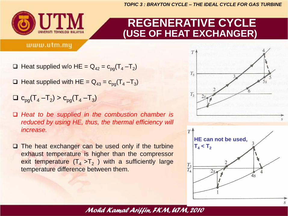
Heat supplied w/o HE = Q42 = cpg(T4 –T2)
Heat supplied with HE = Q43 = cpg(T4 –T3)
cpg(T4 –T2) > cpg(T4 –T3)
Heat to be supplied in the combustion chamber is
reduced by using HE, thus, the thermal efficiency will
increase.
The heat exchanger can be used only if the turbine
exhaust temperature is higher than the compressor
exit temperature (T4 >T2 ) with a sufficiently large
temperature difference between them.
REGENERATIVE CYCLE(USE OF HEAT EXCHANGER)
HE can not be used,
T4 < T2

Mohd Kamal Ariffin, FKM, UTM, 201035
EXAMPLE
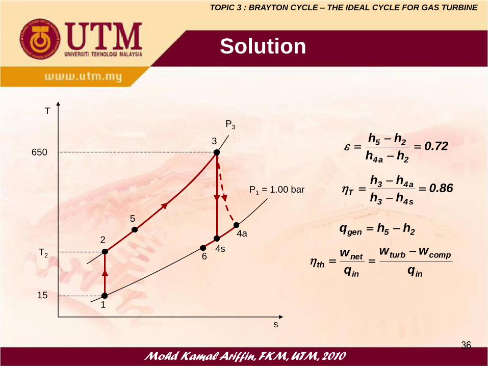
Air enters the compressor of a regenerative gas turbine
power plant at 15 oC and 1.01 bar and the pressure ratio is
9/1.The maximum temperature of the cycle is 650 oC. The
generator has an effectiveness of 75 percent. For a
compressor and turbine efficiency of 0.8 and 0.85
respectively, determine:
a) the amount of heat transfer in the generator
b) the thermal efficiency
c) the work ratio
TOPIC 3 : BRAYTON CYCLE – THE IDEAL CYCLE FOR GAS TURBINE
Mohd Kamal Ariffin, FKM, UTM, 201036
72.0hh
hh
2a4
25
86.0hh
hh
s43
a43T
1
24s
3
4a
5
6
T
s
15
T2
650
P3
P1 = 1.00 bar
25gen hhq
in
compturb
in
netth
q
ww
q
w
TOPIC 3 : BRAYTON CYCLE – THE IDEAL CYCLE FOR GAS TURBINE
Solution

Mohd Kamal Ariffin, FKM, UTM, 201037
Physical arrangement of
an ideal two-stage gas-
turbine cycle with
intercooling, reheating,
and regeneration
GAS TURBINE CYCLE WITH INTERCOOLING,
REHEATING & REGENERATION
TOPIC 3 : BRAYTON CYCLE – THE IDEAL CYCLE FOR GAS TURBINE
The work output of a turbine can be increased by
expanding the gas in stages and reheating it in
between, utilizing a multistage expansion with
reheating.

Mohd Kamal Ariffin, FKM, UTM, 201038
The work input to a two-stage compressor is minimized when equal pressure ratios
are maintained across each stage. This procedure also maximizes the turbine work
output.Thus, for best performance,
Conditions for Best Performance
• Intercooling and reheating always decreasesthermal efficiency unless are accompanied byregeneration.
• Therefore, intercooling and reheating arealways used in conjunction withregeneration.
9
8
7
6
3
4
1
2
P
P
P
P and
P
P
P
P
TOPIC 3 : BRAYTON CYCLE – THE IDEAL CYCLE FOR GAS TURBINE
GAS TURBINE CYCLE WITH INTERCOOLING,
REHEATING & REGENERATION

Mohd Kamal Ariffin, FKM, UTM, 2013
Example 9.4 pg 276
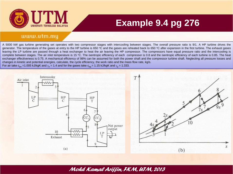
A 5000 kW gas turbine generating set operates with two compressor stages with
intercooling between stages. The overall pressure ratio is 9/1. A HP turbine drives the
generator. The temperature of the gases at entry to the HP turbine is 650 oC and the
gases are reheated back to 650 oC after expansion in the first turbine. The exhaust gases
leaving the LP turbine are passed through a heat exchanger to heat the air leaving the
HP compressor. The compressors have equal pressure ratio and the intercooling is
complete between stages. The air inlet temperature is 15 oC. The isentropic efficiency of
each compressor is 0.8 and the isentropic efficiency of each turbine is 0.85. The heat
exchanger effectiveness is 0.75. A mechanical efficiency of 98% can be assumed for both
the power shaft and the compressor turbine shaft. Neglecting all pressure losses and
changes in kinetic and potential energies, calculate,
a) the cycle efficiency
b) the work ratio
c) the mass flow rate, kg/s.
For air take cpa =1.005 kJ/kgK and a = 1.4 and for the gases take cpg = 1.15 kJ/kgK and
g = 1.333.
Mohd Kamal Ariffin, FKM, UTM, 2013
Example 9.4 pg 276
A 5000 kW gas turbine generating set operates with two compressor stages with intercooling between stages. The overall pressure ratio is 9/1. A HP turbine drives the
generator. The temperature of the gases at entry to the HP turbine is 650 oC and the gases are reheated back to 650 oC after expansion in the first turbine. The exhaust gases
leaving the LP turbine are passed through a heat exchanger to heat the air leaving the HP compressor. The compressors have equal pressure ratio and the intercooling is
complete between stages. The air inlet temperature is 15 oC. The isentropic efficiency of each compressor is 0.8 and the isentropic efficiency of each turbine is 0.85. The heat
exchanger effectiveness is 0.75. A mechanical efficiency of 98% can be assumed for both the power shaft and the compressor turbine shaft. Neglecting all pressure losses and
changes in kinetic and potential energies, calculate, the cycle efficiency, the work ratio and the mass flow rate, kg/s.
For air take cpa =1.005 kJ/kgK and a = 1.4 and for the gases take cpg = 1.15 kJ/kgK and g = 1.333.
Mohd Kamal Ariffin, FKM, UTM, 201041
EXAMPLE 9-8 Pg 515
TOPIC 3 : BRAYTON CYCLE – THE IDEAL CYCLE FOR GAS TURBINE
A gas turbine with two stages of compression and two stages of expansion has
an overall pressure ratio of 8. Air enters each stage of the compressor at 300 K
and each stage of turbine at 1300 K. Both compressors and turbines have the
same pressure ratio. Determine the work ratio and thermal efficiency of the
cycle if,
a) no regenerator
b) ideal regenerator with 100 percent effectiveness.
Mohd Kamal Ariffin, FKM, UTM, 201042
EXAMPLE 9-8 Pg 515
TOPIC 3 : BRAYTON CYCLE – THE IDEAL CYCLE FOR GAS TURBINE
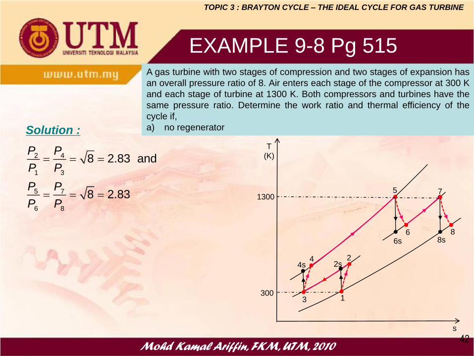
A gas turbine with two stages of compression and two stages of expansion has
an overall pressure ratio of 8. Air enters each stage of the compressor at 300 K
and each stage of turbine at 1300 K. Both compressors and turbines have the
same pressure ratio. Determine the work ratio and thermal efficiency of the
cycle if,
a) no regenerator
2 4
1 3
5 7
6 8
8 2.83 and
8 2.83
P P
P P
P P
P P
Solution :
1
22s
3
44s
5
6s6 8
7
8s
T
(K)
s
1300
300

Mohd Kamal Ariffin, FKM, UTM, 201043
EXAMPLE 9-8 Pg 515
TOPIC 3 : BRAYTON CYCLE – THE IDEAL CYCLE FOR GAS TURBINE
A gas turbine with two stages of compression and two stages of expansion has
an overall pressure ratio of 8. Air enters each stage of the compressor at 300 K
and each stage of turbine at 1300 K. Both compressors and turbines have the
same pressure ratio. Determine the work ratio and thermal efficiency of the
cycle if,
b) ideal regenerator with 100 percent effectiveness
2 4
1 3
6 8
7 9
8 2.83 and
8 2.83
P P
P P
P P
P P
Solution :
1
22s
3
44s
6
7s
7 9
8
9s
T
(K)
s
1300
300
10
5
T2 =T4 =T10
T5 =T7 =T9 ●
●
Mohd Kamal Ariffin, FKM, UTM, 201044
Consider an ideal gas-turbine cycle with two stages of compression and two
stages of expansion. The pressure ratio across each stage of the compressor
and turbine is 3. The air enters each stage of the compressor at 300 K and each
stage of the turbine at 1200 K. Determine:
a) the back work ratio, and
b) the thermal efficiency of the cycle
assuming:
1. no regenerator is used, and
2. a regenerator with 75 percent effectiveness is used.
cpa = 1.005 kJ/kgK, a = 1.4, cpg = 1.15 kJ/kgK and g = 1.33
ASSIGNMENT 2
TOPIC 3 : BRAYTON CYCLE – THE IDEAL CYCLE FOR GAS TURBINE
Mohd Kamal Ariffin, FKM, UTM, 201045
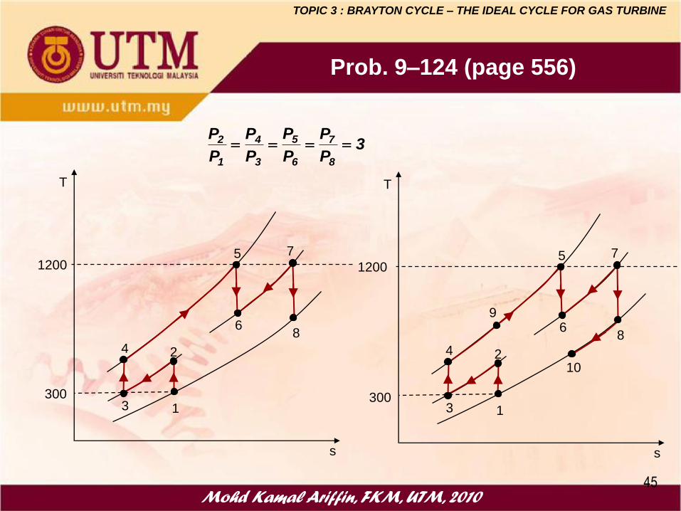
Prob. 9–124 (page 556)
1
2
6
5 7
8
T
s
3
4
300
1200
1
2
6
5 7
8
T
s
3
4
300
1200
9
10
3P
P
P
P
P
P
P
P
8
7
6
5
3
4
1
2
TOPIC 3 : BRAYTON CYCLE – THE IDEAL CYCLE FOR GAS TURBINE

Mohd Kamal Ariffin, FKM, UTM, 201046
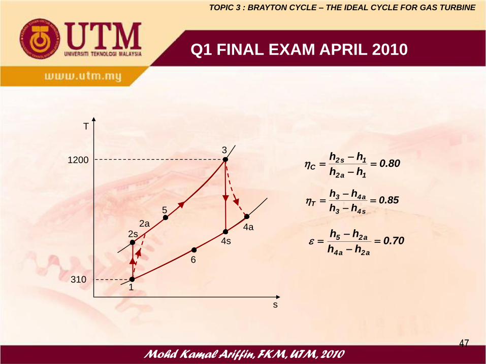
Q1 FINAL EXAM APRIL 2010
Mohd Kamal Ariffin, FKM, UTM, 201047
Q1 FINAL EXAM APRIL 2010
1
2s4s
3
4a
T
s
2a
5
6
310
1200
85.0hh
hh
s43
a43T
80.0hh
hh
1a2
1s2C
70.0hh
hh
a2a4
a25
TOPIC 3 : BRAYTON CYCLE – THE IDEAL CYCLE FOR GAS TURBINE
Mohd Kamal Ariffin, FKM, UTM, 2010
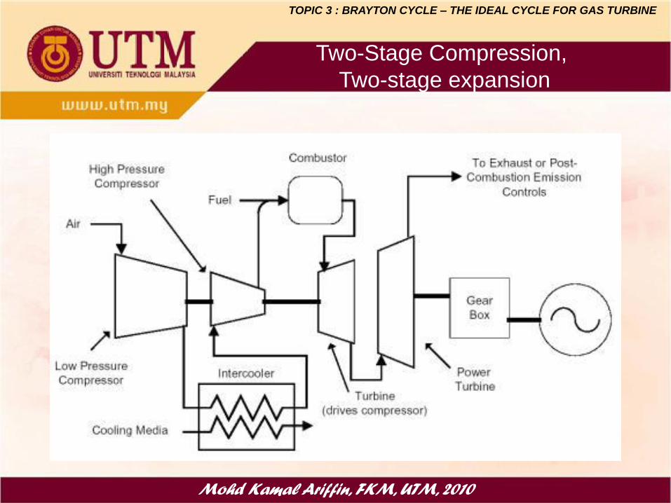
Two-Stage Compression,
Two-stage expansion
TOPIC 3 : BRAYTON CYCLE – THE IDEAL CYCLE FOR GAS TURBINE

Mohd Kamal Ariffin, FKM, UTM, 2010
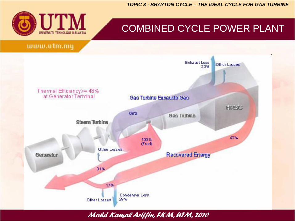
COMBINED CYCLE POWER PLANT
TOPIC 3 : BRAYTON CYCLE – THE IDEAL CYCLE FOR GAS TURBINE

Mohd Kamal Ariffin, FKM, UTM, 2010
COMBINED CYCLE POWER PLANT
TOPIC 3 : BRAYTON CYCLE – THE IDEAL CYCLE FOR GAS TURBINE
Mohd Kamal Ariffin, FKM, UTM, 2010
COMBINED CYCLE POWER PLANT
TOPIC 3 : BRAYTON CYCLE – THE IDEAL CYCLE FOR GAS TURBINE

Mohd Kamal Ariffin, FKM, UTM, 2010
THE END