TOPFLOOR TF110R-TRS - Operator Manual & Service Manual
40
operator manual TF110R-TRS vacuum sweeper
Transcript of TOPFLOOR TF110R-TRS - Operator Manual & Service Manual
operator manual TF110R-TRS vacuum sweeper


TF110R-TRS

Table of contents
I
Table of contents
1 Introduction....................................................................................................................................... 3
1.1 Usage conformant with intended purpose .......................................................................... 3
2 Safety information ............................................................................................................................ 4
3 Device Description ........................................................................................................................... 6
3.1 Initial Startup ....................................................................................................................... 7
4 Operation........................................................................................................................................... 9
4.1 Driving ................................................................................................................................. 9
4.1.1 Forward travel: ................................................................................................... 10
4.1.2 Reverse travel: .................................................................................................. 10
4.2 Sweeping .......................................................................................................................... 11
4.2.1 Main Broom Drive .............................................................................................. 11
4.2.2 Operating the Main Brooms............................................................................... 11
4.3 Operating the Side Brushes .............................................................................................. 12
4.4 Information provided by LED indicators on the battery condition display: ........................ 12
4.5 Operating the Suction ....................................................................................................... 12
4.6 Adjustment of Driver`s Seat .............................................................................................. 13
4.7 Turning Off the Sweeping & Suction Machine .................................................................. 13
4.8 Operating the Filter Cleaning Device ................................................................................ 13
4.9 Emptying the Hopper ........................................................................................................ 14
4.9.1 Removing the Hopper ........................................................................................ 14
4.9.2 Reinserting the Hopper ...................................................................................... 15
5 Maintenance .................................................................................................................................... 16
5.1 Safety Information ............................................................................................................. 16
5.2 Cleaning ............................................................................................................................ 16
5.3 Charging the Batteries ...................................................................................................... 17
5.4 Battery ............................................................................................................................... 18
5.5 Brake ................................................................................................................................. 18
5.5.1 Adjusting the Brake ........................................................................................... 18
5.6 Brake Check ..................................................................................................................... 19
5.6.1 Correct Operating of Brake................................................................................ 19
5.7 Steering ............................................................................................................................. 20

Table of contents
II TF110R-TRS
5.8 Replacement of Filter ........................................................................................................ 20
5.8.1 Removal............................................................................................................. 20
5.8.2 Reinsertion ........................................................................................................ 21
5.9 Main Brooms Replacement............................................................................................... 21
5.9.1 Dismounting the Main Brooms .......................................................................... 21
5.9.2 Installing the Main Brooms ................................................................................ 23
5.10 Setting the Main Brooms................................................................................................... 24
5.10.1 Sweeping Contour Adjustment .......................................................................... 24
5.10.2 Adjusting the Sweeping Contour ....................................................................... 25
5.10.3 Further Possible Adjustment: ............................................................................ 25
5.11 Replacing the Side Brush ................................................................................................. 26
5.11.1 Dismounting the Side Brush .............................................................................. 26
5.11.2 Mounting the Side Brush ................................................................................... 26
5.12 Adjustment of the Side Brush ........................................................................................... 27
5.13 Wheels .............................................................................................................................. 28
5.14 Fuses ................................................................................................................................ 28
5.15 Maintenance Chart ............................................................................................................ 28
5.15.1 Daily maintenance ............................................................................................. 28
5.15.2 After each 50 operating hours also ................................................................... 28
5.15.3 After each 100 operating hours also ................................................................. 29
5.15.4 After each 200 operating hours also ................................................................. 29
5.16 Disturbances, Disturbance Display, Remedy ................................................................... 30
5.17 Technical Data .................................................................................................................. 31
5.18 Product Marking ................................................................................................................ 32
5.19 Disposal ............................................................................................................................ 32
5.20 Accessories and spare parts ............................................................................................ 33
5.21 Service .............................................................................................................................. 33
5.22 Transport ........................................................................................................................... 33
6 EC Declaration of conformity ........................................................................................................ 34

3
1 Introduction
This operating manual contains instructions for using the hand-operated
sweeper.
Our products are subject to continuous improvement. Therefore, design
changes that were made after this manual went to print could not be
incorporated. If you have any questions, please contact our Service
department.
The operating manual must be read and applied by all persons who
operate the sweeper.
Apart from the operating manual and the regulations for accident pre-
vention applicable in the country of use and the location of use, the
common, recognised rules for safe and technically correct working must
also be followed.
1.1 Usage conformant with intended purpose
The appliance is intended exclusively for sweeping on solid surfaces (for
example: parking areas, walkways, shop floors). The area to be swept
should not be wet.
The sweeper may only be used by reliable and instructed personnel.
Prevent children, juveniles and other unauthorised persons from using
the machine (e.g. by pulling out the key after use).
Any other use, or any use over and above that, will be considered to be
non-conformant with intended purpose. The manufacturer rejects any
and all liability for damage resulting from such use. The risk is that of the
user alone.
Usage conformant with intended purpose also includes compliance with
the operating manual and the inspection and maintenance specifica-
tions. Drive the sweeper only along expressly marked routes and spac-
es.

4 TF110R-TRS
2 Safety information
1. The machine should only be used in a flawless state, as
well as in keeping with its intended purpose, in a safety-
conscious and risk-conscious manner and in compliance
with these operating instructions.
2. In addition to the operating manual, please heed general le-
gal and other binding regulations for accident prevention
and environmental protection.
3. Sweeping and picking up of flammable, toxic or explosive
substances, along with flammable gases or diluted acids
and solvents, burning or smouldering objects is prohibited!
4. The appliance is not suitable for picking up fluids, cables,
cords, wires or the like.
5. The machine should only be used with the hopper fitted to
prevent injuries caused by parts being slung out.
6. Transporting loads with the sweeper is not allowed.
7. Faults should be eliminated immediately, particularly those
that could impair safety.
8. Do not make any changes, modifications or additions to the
sweeper without the approval of the manufacturer.
9. Replacement parts must meet manufacturer specifications.
This is always ensured by using original replacement parts.
10. Ensure that operating media, auxiliary media and replace-
ment parts are disposed of in a safe and environmentally-
friendly manner, particularly batteries!
11. Suitable non-slip footwear should be worn to avoid acci-
dents.
12. If you have any questions, please contact our Service de-
partment.
13. Persons (including children) who are not able to use this
machine safely due to their physical, sensory or mental ca-
pabilities or their inexperience or lack of knowledge may not
use this machine without the supervision or instruction by a
responsible person! Children should be supervised to en-
sure that they do not play with the appliance.
14. Caution: loose clothing can be caught and drawn in on rotat-
ing parts.
15. The operating instructions provided by the battery manufac-
turer relating to his product and legal specifications for the
handling of accumulator batteries should be heeded!
5
16. Charge flat batteries directly after use and only in well-
ventilated rooms.
17. Keep naked flames and electrical sparks away from the
charging area, since a highly-explosive electrolytic gas mix-
ture is generated when batteries are being charged.
18. Note that the accumulator batteries are filled with battery ac-
id.
19. Batteries should always be kept clean and dry to avoid
leakage currents! Never short-circuit battery poles!
20. Smoking, eating and drinking should be avoided in the vicin-
ity of the battery charging station to avoid risks to health.
21. Batteries should only be charged with the hood opened and
secured with the holder.

6 TF110R-TRS
3 Device Description
The Sweeping & Suction Machine is driven by electric motors. The
TF110R-TRS operates by using two pivotal side brushes to convey the
sweepings to the two Main Brooms arranged parallel to the direction of
travel. These throw the sweepings overhead into the hopper positioned
behind it. If necessary, the dust stirred up by the Main Brooms is caught
by the dust suction unit in a lamellar filter inside the machine. The lamel-
lar filter is cleaned by an electrically controlled filter cleaning device.
1 battery condition display 2 switch for the direction of travel
3 switch for Main Brooms 4 switch for side brushes
5 switch for suction 6 switch for filter cleaning
7 lowering lever for the main
broom
8 key switch
9 battery master switch (EMER-
GENCY OFF)
1 steering wheel with steer-
ing pillar
2 driver`s seat
3 main trim panel
4 steering pillar trim
5 hopper
6 front trim panel
7 driving wheel
8 left side trim panel
9 rear wheel with drum break
10 lowering lever for side
brushes
11 pivotal side brushes

7
3.1 Initial Start-up
The Sweeping & Suction Machine standard delivery is without batteries
or charging device.
Optional:
The Sweeping & Suction Machine is supplied with batteries
Standard:
Open the transport packaging.
Take off the complete hood. Lift up hood at back and lift the front
spigots of the hood out of the retaining.
Fit in the batteries.
Connect the batteries. Compare technical data circuit diagram.
Replace the hood panel.
Mount the side brushes (cf. 5.11.2).
The Sweeping & Suction Machine is ready for use.
Drive the Sweeping & Suction Machine over a ramp out of the
transport packaging.
Use a unit ramp. The ramp must be designed in such a way as to allow
the rear wheel as well as the drive wheels to travel across it.
If this is not observed, damages to the Sweeping & Suction Machine
mechanics will occur.
1 Elements of the Transport
Packaging.
8 TF110R-TRS
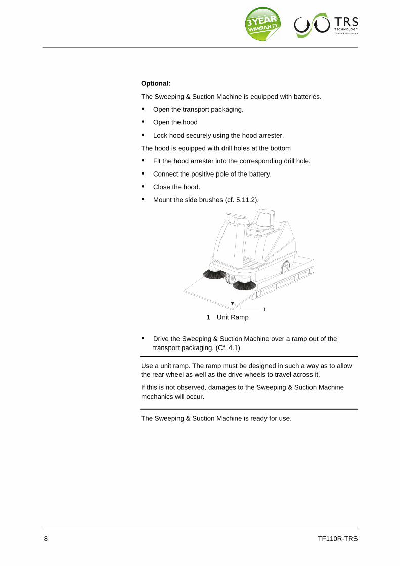
Optional:
The Sweeping & Suction Machine is equipped with batteries.
Open the transport packaging.
Open the hood
Lock hood securely using the hood arrester.
The hood is equipped with drill holes at the bottom
Fit the hood arrester into the corresponding drill hole.
Connect the positive pole of the battery.
Close the hood.
Mount the side brushes (cf. 5.11.2).
1 Unit Ramp
Drive the Sweeping & Suction Machine over a ramp out of the
transport packaging. (Cf. 4.1)
Use a unit ramp. The ramp must be designed in such a way as to allow
the rear wheel as well as the drive wheels to travel across it.
If this is not observed, damages to the Sweeping & Suction Machine
mechanics will occur.
The Sweeping & Suction Machine is ready for use.

9
4 Operation
4.1 Driving
Starting the Sweeping & Suction Machine
Sit down in the driver`s seat
The Sweeping & Suction Machine cannot be started if the driver's
seat is not weighed down.
Check position of direction of travel switch.
The direction of travel switch is a toggle switch with two positions.
1 Battery condition display 2 direction of travel switch
3 Pilot lamp forward travel 4 Pilot lamp reverse travel
5 key switch 6 battery master switch
Insert the battery master switch into the socket.
Press it down and turn it clockwise until it is firmly latched.
Now pull up the battery master switch.
Insert the key into the key switch.
Turn the key clockwise.
On the control panel a red LED starts flashing. (This indicates machine
ready for operation.) After that the LEDs indicating the battery's charg-
ing condition light up.
Depress the brake pedal.
Release the parking brake.
Actuate the direction of travel switch.

10 TF110R-TRS
4.1.1 Forward travel:
Push the direction of travel switch forward.
Optical signal:
Green pilot lamp on the switch
4.1.2 Reverse travel:
Push the direction of travel switch backward.
Optical signal:
Red pilot lamp on the switch,
Acoustical signal: Beeper (optional)
The speed of the Sweeping & Suction Machine can be adjusted with
infinite variability by depressing the accelerator.
1 Parking brake
2 Brake pedal
3 Accelerator

11
4.2 Sweeping
Do not switch on suction when debris is wet. This will cause damage to
the suction device and the filter. Provide good aeration when using the
machine in closed rooms or buildings.
Do not sweep up materials that may cause health impairment.
1 switch for the Main Brooms 2 switch for the side brushes
3 switch for the suction 4 switch for the filter cleaning
5 lowering lever for the Main Broom
4.2.1 Main Broom Drive
The Main Broom drive is situated on the right side of the Sweeping &
Suction Machine facing in driving direction.
The Main Brooms are driven by an electric motor via a chain.
The chain is deflected by a sprocket and guided over the sprockets of
the roller drive.
A spring biased chain tensioner keeps the chain tight.
Grease the sprockets at regular intervals. Cf. Maintenance Chart.
To grease the sprockets, open the hood and remove the side trim panel.
4.2.2 Operating the Main Brooms
Start the Sweeping & Suction Machine
Switch the toggle switch for the Main Brooms to ON Position.
Unlatch the lowering lever of the Main Broom.
The pilot lamp on the switch lights up.
The Main Brooms begin rotating.
Stopping Main Brooms Operation
Pull lowering lever of the Main Brooms towards yourself
Switch toggle switch for the Main Brooms to OFF position
Let the lever snap in arresting position
12 TF110R-TRS
4.3 Operating the Side Brushes
The side brushes are fixed to swingers.
Whenever the side brushes hit an obstacle they swing back under the
vehicle to avoid damages.
Start the Sweeping & Suction Machine.
Unlatch the lowering lever of the side brushes.
Switch toggle switch for the side brushes to ON position.
Push the lever down.
The pilot lamp on the switch lights up.
The side brushes begin to rotate.
Stopping Side Brush Operating:
Switch toggle switch for the side brushes to OFF position.
Pull up the lowering lever for the side brushes. Let the lever snap in
arresting position
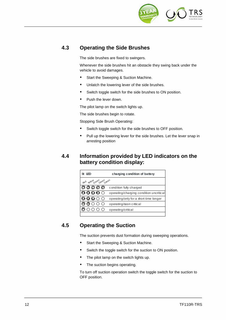
4.4 Information provided by LED indicators on the battery condition display:
charging condition of batterylit LED
Red
Y
ellow
G
reen
G
reen
Green
condition fully charged
operating/charging condition uncritical
operating/only for a short time longer
operating/soon c ritical
operating/critical
4.5 Operating the Suction
The suction prevents dust formation during sweeping operations.
Start the Sweeping & Suction Machine.
Switch the toggle switch for the suction to ON position.
The pilot lamp on the switch lights up.
The suction begins operating.
To turn off suction operation switch the toggle switch for the suction to
OFF position.
13
Please observe!
Do not switch on suction when sweepings are wet.
This will cause damage to the suction device!
To turn off suction operation switch the toggle switch for the suction to
OFF position.
4.6 Adjustment of Driver`s Seat
Loosen the seat arresting device and shift the driver's seat on the
seat support to a position that feels comfortable to you.
4.7 Turning Off the Sweeping & Suction Machine
Depress the brake pedal.
Lock the brake by pulling the locking lever towards the driver's seat.
When the brake now is relieved the brake pedal must remain in de-
pressed position.
All of the pilot lamps on the switch are off.
Switch off all actuators.
Lift up the side brushes and arrest the lowering lever for the side
brushes.
Lift up the Main Brooms and arrest the lowering lever for the Main
Brooms.
Turn the key anticlockwise and remove it from the key switch.
Turn the battery master switch anticlockwise and remove it from the
socket.
4.8 Operating the Filter Cleaning Device
The filter cleaning device prevents the lamellar filter from being blocked
by debris.
Switch off suction.
Wait until ventilation wheel stands still.
Apply filter cleaning device at regular intervals.
Depress the toggle switch for the filter cleaning device for about 5 to
10 seconds.
The filter cleaning device begins operation.

14 TF110R-TRS
4.9 Emptying the Hopper
The hopper is the place where the sweepings are collected.
It is positioned at the back of the Sweeping & Suction Machine.
The hopper must be emptied regularly and especially after each use.
4.9.1 Removing the Hopper
Turn the hopper locking upward.
Pull out the hopper from the Sweeping – & Suction Machine by the grip-
ping handle until the front hopper guide rails are free.
1 locking device 2 recessed grip
3 locking device 4 guide rail
5 roller 6 Hopper guides
At the back of the hopper, two guiding rollers are installed to make the
removal easier.
Lower the hopper to the ground
A number of rollers and a recessed grip are positioned at the bottom of
the hopper.
Remove the hopper completely from the Sweeping & Suction Ma-
chine.
In order to empty the hopper, use the free hand to take hold of the
recessed grip.
The sweepings are discharged through the opening at the bottom of
the hopper.
Empty sweepings into appropriate containers only.

15
4.9.2 Reinserting the Hopper
Place the hopper before the back of the machine.
Bring the hopper’s front guides up to the same level as the guide
rails.
Slide the hopper into the Sweeping & Suction Machine.
Turn the locking device downward.

16 TF110R-TRS
5 Maintenance
5.1 Safety Information
Only complete the type of maintenance work described in the following
chapter. All other maintenance and upkeep work may only be carried
out by the manufacturer or by companies and persons authorised by the
manufacturer, who are familiar with the relevant safety specifications,
because portable devices in industrial use are subject to the safety test
according to VDE 0701.
Closely follow the steps listed in the maintenance instructions. The im-
proper completion of maintenance tasks may result in malfunctions
when using the sweeper and may possibly render the warranty granted
null and void.
When working on the electrical system, the battery should be discon-
nected.
Maintenance work/ troubleshooting at the electric motor must not be
done while the electric motor is running.
Use only flawless and appropriate tools to complete maintenance work.
Note the requirements for spare parts (see Spare parts).
If covers and/or safety devices were removed during maintenance
work/repairs, they will have to be reattached prior to starting the sweep-
er.
For carrying out any work on the sweeper, it must be switched off and
secured from rolling away by accident.
5.2 Cleaning
The suction sweeper may only be cleaned in the off state, when it is dry.
The suction sweeper is a machine with electrical components.
Moisture damages the electronics of the device. Moisture can re-
sult in leakage currents and short-circuits!
Do not use any high-pressure cleaners
WARNING
17
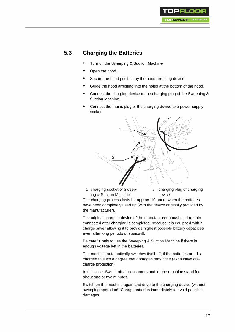
5.3 Charging the Batteries
Turn off the Sweeping & Suction Machine.
Open the hood.
Secure the hood position by the hood arresting device.
Guide the hood arresting into the holes at the bottom of the hood.
Connect the charging device to the charging plug of the Sweeping &
Suction Machine.
Connect the mains plug of the charging device to a power supply
socket.
1 charging socket of Sweep-
ing & Suction Machine
2 charging plug of charging
device
The charging process lasts for approx. 10 hours when the batteries
have been completely used up (with the device originally provided by
the manufacturer).
The original charging device of the manufacturer can/should remain
connected after charging is completed, because it is equipped with a
charge saver allowing it to provide highest possible battery capacities
even after long periods of standstill.
Be careful only to use the Sweeping & Suction Machine if there is
enough voltage left in the batteries.
The machine automatically switches itself off, if the batteries are dis-
charged to such a degree that damages may arise (exhaustive dis-
charge protection)
In this case: Switch off all consumers and let the machine stand for
about one or two minutes.
Switch on the machine again and drive to the charging device (without
sweeping operation!) Charge batteries immediately to avoid possible
damages.
18 TF110R-TRS
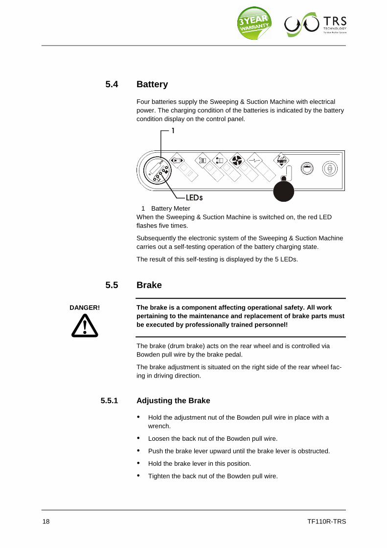
5.4 Battery
Four batteries supply the Sweeping & Suction Machine with electrical
power. The charging condition of the batteries is indicated by the battery
condition display on the control panel.
1 Battery Meter
When the Sweeping & Suction Machine is switched on, the red LED
flashes five times.
Subsequently the electronic system of the Sweeping & Suction Machine
carries out a self-testing operation of the battery charging state.
The result of this self-testing is displayed by the 5 LEDs.
5.5 Brake
The brake is a component affecting operational safety. All work
pertaining to the maintenance and replacement of brake parts must
be executed by professionally trained personnel!
The brake (drum brake) acts on the rear wheel and is controlled via
Bowden pull wire by the brake pedal.
The brake adjustment is situated on the right side of the rear wheel fac-
ing in driving direction.
5.5.1 Adjusting the Brake
Hold the adjustment nut of the Bowden pull wire in place with a
wrench.
Loosen the back nut of the Bowden pull wire.
Push the brake lever upward until the brake lever is obstructed.
Hold the brake lever in this position.
Tighten the back nut of the Bowden pull wire.
DANGER!

19
1 Bowden pull wire guiding 2 Bowden pull wire
3 adjustment nut 4 back nut
5 brake pulley 6 brake lever
7 brake pulley arresting
Now conduct a brake check.
5.6 Brake Check
Free Movement of Rear Wheal
You must be able to move the Sweeping & Suction Machine by pushing
when the brake is released.
The rear wheel must not be blocked. Brakes that are set too tightly
damage the brake drum.
5.6.1 Correct Operating of Brake
Carefully drive a few meters at moderate speed.
Depress the brake pedal. The Sweeping & Suction Machine must stop.
If the brake check should not render a satisfying result the setting pro-
cedure must be repeated.
Further Setting Possibility:
The Bowden pull wire does not allow tightening in the way described
above any longer.
Loosen the brake pulley arresting.
Lift the brake lever up until it is obstructed.
Hold the brake lever in this position.
Pull the brake pulley down and push the brake pulley arresting up-
ward.
Fasten the brake pulley arresting.

20 TF110R-TRS
Carry out the above described brake check.
5.7 Steering
The steering transferral to the rear wheel is managed by a chain and
two chain sprockets.
Grease the chain sprockets at regular intervals. Cf. Maintenance Chart.
5.8 Replacement of Filter
The filter removes fine dust.
The filter is cleaned by an electrical vibrating device.
5.8.1 Removal
Open the hood.
Lock hood securely using the hood arrester.
The filter is held in the fixture by 4 star handles.
1 star handle 2 star handle
Loosen the top two star handles.
Swing up the top angular bracket.
Loosen the bottom two star handles.
Pull the filter out of the fixture.

21
5.8.2 Reinsertion
Place the filter into the lower angular bracket.
Swing the upper bracket over the filter.
Tighten the top star handles slightly.
Tighten star handles evenly crosswise so that the filter snugly fits all
around the seal.
Adjust the bolts and the nuts in a way that provides the filter with the
best possible sealing inside the casing.
1 star handle
2 angular brackets
3 filter (see sticker)
5.9 Main Brooms Replacement
5.9.1 Dismounting the Main Brooms
Turn off the Sweeping & Suction Machine.
Switch off the EMERGENCY OFF to avoid accidental starting.
Pull lowering lever of the Main Brooms.
Arrest the lowering lever.
Loosen the bolts of the left side trim panel facing in driving direction.

22 TF110R-TRS
1 fastening bolts of side trim panel
Remove the side panel.
The roller swing is held in place by three star handles.
Loosen the star handles.
Remove the roller swing.
1 open star handle 2 star handle with marking
3 roller swing 4 star handle
5 turning lever
Pull the Main Brooms out of the machine and remove any debris,
cords, etc., from the roller tunnel and from the pick-up pins.

23
5.9.2 Installing the Main Brooms
Push the Main Brooms under the machine.
Observe the Main Brooms' sense of rotation while sliding them in.
1 forward drive 2 direction of travel of the
Main Brooms
Each roller end is equipped with a keyway.
Turn the Main Broom until the pick-up pin of the rear roller swing fits into
the keyway of the Main Broom.
Slide the Main Brooms in as far as possible.
Set the front roller swing onto the free Main Broom ends.
The roller swing is equipped with two turning levers.
Each turning lever end is equipped with one pick-up pin.
1 threaded rods 2 Main Broom keyway
3 pick-up pin
Turn the turning lever until the pick-up pin fits into the keyway of the
Main Brooms.
Push the roller swing over the threaded rods.
Make sure the Main Brooms are fitted on both sides by the keyway
into the pick-up pins and that all star handles are firmly tightened.
Fasten the side trim panel.

24 TF110R-TRS
5.10 Setting the Main Brooms
5.10.1 Sweeping Contour Adjustment
For best cleaning results and to ensure the highest possible device effi-
ciency, the Main Brooms are equipped with a sweeping contour.
The sweeping contour should be set to approx. 50-60 mm at the rear
roller.
Establishing the Sweeping Contour:
Drive the Sweeping & Suction Machine to an area to be cleaned. Switch
on the Main Brooms without moving the sweeping machine. Allow the
Main Brooms to run for about one or two minutes without moving. Lift
the Main Brooms. Stop Main Brooms operation and drive forward a few
meters. The sweeping track visible on the ground is the sweeping con-
tour.
25
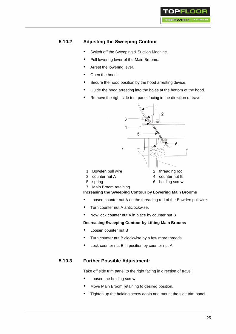
5.10.2 Adjusting the Sweeping Contour
Switch off the Sweeping & Suction Machine.
Pull lowering lever of the Main Brooms.
Arrest the lowering lever.
Open the hood.
Secure the hood position by the hood arresting device.
Guide the hood arresting into the holes at the bottom of the hood.
Remove the right side trim panel facing in the direction of travel.
1 Bowden pull wire 2 threading rod
3 counter nut A 4 counter nut B
5 spring 6 holding screw
7 Main Broom retaining
Increasing the Sweeping Contour by Lowering Main Brooms
Loosen counter nut A on the threading rod of the Bowden pull wire.
Turn counter nut A anticlockwise.
Now lock counter nut A in place by counter nut B
Decreasing Sweeping Contour by Lifting Main Brooms
Loosen counter nut B
Turn counter nut B clockwise by a few more threads.
Lock counter nut B in position by counter nut A.
5.10.3 Further Possible Adjustment:
Take off side trim panel to the right facing in direction of travel.
Loosen the holding screw.
Move Main Broom retaining to desired position.
Tighten up the holding screw again and mount the side trim panel.
26 TF110R-TRS
Original roller diameter: 285 mm.
When diameter has decreased to 245 mm, the roller needs to be re-
placed.
5.11 Replacing the Side Brush
5.11.1 Dismounting the Side Brush
Turn off the Sweeping & Suction Machine.
Pull up the lowering lever for the side brushes.
Arrest the lowering lever.
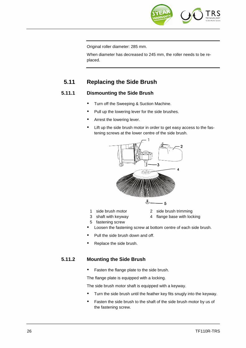
Lift up the side brush motor in order to get easy access to the fas-
tening screws at the lower centre of the side brush.
1 side brush motor 2 side brush trimming
3 shaft with keyway 4 flange base with locking
5 fastening screw
Loosen the fastening screw at bottom centre of each side brush.
Pull the side brush down and off.
Replace the side brush.
5.11.2 Mounting the Side Brush
Fasten the flange plate to the side brush.
The flange plate is equipped with a locking.
The side brush motor shaft is equipped with a keyway.
Turn the side brush until the feather key fits snugly into the keyway.
Fasten the side brush to the shaft of the side brush motor by us of
the fastening screw.

27
5.12 Adjustment of the Side Brush
Operational wear necessitates additional adjustment of the side brush-
es.
Turn off the Sweeping & Suction Machine.
Unlatch the lowering lever of the side brushes.
Push down the lowering lever.
Loosen the bolts of the front panel.
Remove the front panel.
1 bolts for the front panel
Loosen the bolt of the side brush level adjustment.
Move the side brush to the desired position. .
Tighten the bolt of the side brush level adjustment.
1 level adjustment bolt for
side brush
Fasten the front panel.
28 TF110R-TRS
5.13 Wheels
The Sweeping & Suction Machine is equipped with three wheels.
The standard rear wheel tire is made of solid rubber.
The two drive wheels are standard equipped with pneumatic tires.
Optionally the drive wheels are delivered with solid rubber tires.
Defective tires must be repaired or replaced by expert shops only.
Deliver the complete wheel (rim and tire) to the tire shop.
5.14 Fuses
The Fuse box is positioned on the right side under the hood, facing in
driving direction.
The fuses are arranged in the same order as the instruments on the
control panel.
Do not repair fuses
Do not replace fuses by stronger fuses.
This will damage the system
It may lead to a short-circuit and possibly to a fire.
5.15 Maintenance Chart
5.15.1 Daily maintenance
Check battery acid level, if required replenish distilled water.
Charge battery.
Check if machine is damaged or impaired in any way.
Check condition of dust filter and clean if necessary.
Empty hopper.
5.15.2 After each 50 operating hours also
Check if battery leaks acid.
Clean and grease battery poles.
Check if Main Brooms are worn or cluttered. Replace if required.
Check sweeping contour, readjust if required.
Check if side brush adjustment is worn, if required readjust or re-
place.

29
Search brush - roller tunnel for jammed particles and seized up dirt
that may narrow the brush tunnel and obstruct free roller brush
movement.
5.15.3 After each 100 operating hours also
Check cable isolation, replace cables if required.
Check if cable connections are tight.
Grease steering chain.
Grease Main Broom drive chain.
Clean dust filter, replace if necessary.
Search suction for obstacles, clean.
Conduct trial run to check all operating elements.
Check if roller drive chain is elongated or loosened.
Check all bearings for wear.
Check if seals are damaged or dislocated.
5.15.4 After each 200 operating hours also
Check operation of electric motors.
Check if carbon brushes are worn, replace if required.
Check steering clearance, tighten chain if required.
Check all electrical system components whether they are soiled.

30 TF110R-TRS
5.16 Disturbances, Disturbance Display, Remedy
Disturbance Possible Cause Remedy
No operating display at control
panel:
EMERGENCY OFF not switched
on Key switch not switched on
Seat contactor or hood contactor
not actuated
Fault in electrical wiring
Battery empty
Turn EMERGENCY OFF switch
into socket
Turn key switch and check cor-
rect load
Check plug connections
Charge battery
No operation of propelling drive
in-spite of display at control pan-
el:
Direction of travel switch was set
to forward or reverse travel dur-
ing start
Accelerator was depressed at
start
Fuse 1 defective
Fault in electrical connections
Problems in electronic control
Switch to neutral and then again
to the desired position
Release accelerator
Replace fuse
Check plug connections and
compare indication by red LED at
control panel
No operation of one of the elec-
trical consumers:
Fuse defective
Fault in electric connections
Fuses permanently defective
Replace fuse
Check plug connections of corre-
sponding system component:
check especially Main Brooms
whether obstructed by bands,
cables, strings
Sweeping result unsatisfactory:
Side brush(es) or main Main
Brooms not lowered
Side brush(es) or main sweeping
rollers worn
Trajectory clogged by dirt
Main Broom(s) do not operate
Dust formation too great
Suction turbine does not operate
Filter heavily polluted
Filter not correctly fitted
Leakage and subsequent aspira-
tion of
false air in the filter chamber
Lower
Adjust
Check if roller trim panel is im-
paired by jammed debris
Correctly fitted? Does motor
revolve?
if required switch off side brushes
Check is electrically defective
Clean filter
check for tight fit
check if false air is sucked in
Fuses of the Main Broom do not
remain set
Brush rollers are jammed by dirt,
cords, strings or the like
Dismount brush rollers and clean
them

31
Disturbance Possible Cause Remedy
Fuses of the side brushes do
remain set
Side brushes are jammed by dirt,
cords, strings or the like
Check side brushes and remove
obstacles
Fuse of the suction fan does not
remain set
Suction fan does not move freely Check ventilator wheel and re-
move any obstruction
Fuse of propelling drive does not
remain set
Drive wheels obstructed Jack up the Sweeping & Suction
Machine check differential opera-
tion of wheels and free running
5.17 Technical Data
Dimension and Weight
Length: approx. 1.450 mm
Width: 900 mm
Height: approx. 1165 mm upper edge of
steering wheel
Weight:
without batteries 201 Kg
with batteries 331 Kg
Sweeping Width
without side brush 700 mm
with one side brush 900 mm
with two side brushes 1.100 mm
Hopper Volume 90 Ltrs.
Climbing Capacity 20%
Speed 0-6 km/h
Filter Area 4 m²
Air Volume of the 900 m³
Dust Suction
supporting frame Steel construction, powder coated
Trim Panel Parts impact resistant plastic
Electrical Installation
Power supply: 4 batteries with je
6V 180 Ah (5h) each. Running time
of battery version:
>4 h
Fuses:

32 TF110R-TRS
Electrical Installation
Vibrator: 24 V 10A
Ventilator: 24 V 30A
Side brushes: 24 V 20A
Main Brooms: 24 V 40A
Driving switch: 24 V 45A
Maximum Airborne Sound Level: 71 dB (A)
Weighted Effective Acceleration
Value upper extremities are sub-
jected to
<2,5m/s²
Tires
Front: 1 solid rubber tire
Back : 2 pneumatic tires
Optional: 2 solid rubber tires
Tire size: 260 x 85
Air pressure: 5,5 bar
Brake
Drum brake Acting on front wheel
Parking brake
5.18 Product Marking
5.19 Disposal
Dispose of faulty parts, especially electrical components, batteries and
plastic parts according to the locally applicable waste disposal specifica-
tions.
Used batteries must be disposed of according to Directive 2006/66/EC.
Vacuum Sweeper TF110R-TRS
Rated Power: KW Serial Number: Supplier: Crescent Industrial Berrington House Berrington Road Leamington Spa CV31 1NB
33
5.20 Accessories and spare parts
Accessories and spare parts must conform to the requirements of the
manufacturer. This is ensured by using genuine replacement parts.
5.21 Service
Crescent Industrial
Berrington House
Berrington Road
Leamington Spa
CV31 1NB
0845 33 77 695
5.22 Transport
Transport the machine only in the switched-off condition, sufficiently well
fastened.

34 TF110R-TRS
6 EC Declaration of conformity
according to the EC Machine Directive 2006/42/EC, Appendix II, No. 1A
Mr. Stephen Stacey – Management of Crescent Industrial, 170 Masons Road, Stratford-Upon-Avon, Warwickshire, CV37 9NF - is authorized to arrange technical information.
We hereby declare that the machine described below corresponds, in its conception and construction, as well as the model brought into use by us, to the basic safety and health requirements of the EC Machine Directive 2006/42/EC. In case of a change being made that has not previously been agreed with us, this declaration will lose its validity.
Supplier: Crescent Industrial Berrington House, Berrington Road, Leamington Spa, CV31 1NB Designation of the machine: TF110R-TRS HD Machine type: Vacuum Sweeper with Tandem-Roller-System (TRS) relevant EC Directives: Directive 2006/42/EC
Directive 2000/14/EC Directive 2004/108/EC
The following standards, in particular, were applied: EN 292 EN 294 DIN EN 61000-6-2 DIN EN 60335-1 DIN EN 60335-2-69 DIN EN 60335-2-72
Leamington Spa, 29 November 2012 ……………………………… Stephen Stacey (Senior Partner)

35

36 TF110R-TRS
Distributed by
tel 0845 33 77 695
Berrington House f 0845 33 78 695
Berrington Road, Leamington Spa e [email protected]
Warwickshire CV31 1NB w www.crescentindustrial.co.uk