Topaz i.MX25 Development Kit Technical Reference ManualDevelopment+Kit...Topaz i.MX25 Development...
13
Copyright © 2010 Device Solutions Ltd, All rights reserved. Revision: 0.7 30 April 2010 Topaz i.MX25 Development Kit Technical Reference Manual Quick Reference What is in this document? Detailed information about the Topaz Development Kit hardware Mechanical drawings What is not in this document (and where do I find it)? Setup information. See the Getting Started Guide. Detailed software development information. Refer to documentation provided with the Operating System Build (Windows CE, Linux or .NET Micro Framework) for this information. Where can I get support? http://DeviceSolutions.net/Support.aspx Where can I find out about updates? Device Solutions Blog: http://blog.DeviceSolutions.net
Transcript of Topaz i.MX25 Development Kit Technical Reference ManualDevelopment+Kit...Topaz i.MX25 Development...
Copyright © 2010 Device Solutions Ltd, All rights reserved.
Revision: 0.7 30 April 2010
Topaz i.MX25 Development Kit Technical Reference Manual
Quick Reference
What is in this document?
Detailed information about the Topaz Development Kit hardware
Mechanical drawings
What is not in this document (and where do
I find it)?
Setup information. See the Getting Started Guide.
Detailed software development information. Refer to documentation provided with the Operating System Build (Windows CE, Linux or .NET Micro Framework) for this information.
Where can I get support? http://DeviceSolutions.net/Support.aspx
Where can I find out about updates?
Device Solutions Blog: http://blog.DeviceSolutions.net
Topaz i.MX25 Development Kit Technical Reference Manual
www.DeviceSolutions.net Page 2
Table of Contents
1 INTRODUCTION ............................................................................................................... 3
2 SYSTEM COMPONENTS.................................................................................................. 4
2.1 TOPAZ CPU MODULE ....................................................................................................... 5
2.2 USER INTERFACE COMPONENTS ....................................................................................... 5
2.3 COMMUNICATIONS COMPONENTS .................................................................................... 6
2.4 FILE STORAGE................................................................................................................... 6
2.5 EXPANSION ........................................................................................................................ 7
2.6 POWER SUPPLY ................................................................................................................. 7
2.7 JTAG CONNECTOR ........................................................................................................... 7
3 CONNECTORS AND SIGNALS ........................................................................................ 8
3.1 CONNECTOR SUMMARY .................................................................................................... 8
3.2 CONNECTOR DETAILS ....................................................................................................... 9
4 SPECIFICATIONS ........................................................................................................... 13
4.1 TEMPERATURE RATINGS ................................................................................................ 13
4.2 DC OPERATING CONDITIONS.......................................................................................... 13
4.3 POWER CONSUMPTION ................................................................................................... 13

Topaz i.MX25 Development Kit Technical Reference Manual
www.DeviceSolutions.net Page 3
1 Introduction The Topaz i.MX25 Development Kit is a flexible development system that enables rapid prototyping of devices using the Device Solutions Topaz CPU module.
At the heart of the Topaz CPU module is the Freescale i.MX25 processor.
This document details the technical specifications of the Topaz Development Kit. For information on getting started, please refer to the Getting Started Guide.
The product details presented in this manual are subject to change. Please contact Device Solutions for the latest information before beginning any new designs based on this information.
For more information, you should also refer to:
Topaz Technical Reference Manual
Topaz i.MX25 Development Kit Schematics
Help provided with the Operating System you are using with the Topaz Development Kit
Application notes published on the Device Solutions web site
Topaz i.MX25 Development Kit Technical Reference Manual
www.DeviceSolutions.net Page 4
2 System Components This section starts give details on each of the system components that makes up the Topaz i.MX25 Development Kit.
It is divided into the following parts:
Block Diagram
Topaz CPU module
User Interface Components
Communications Components
Expansion and File Storage
Power Supply
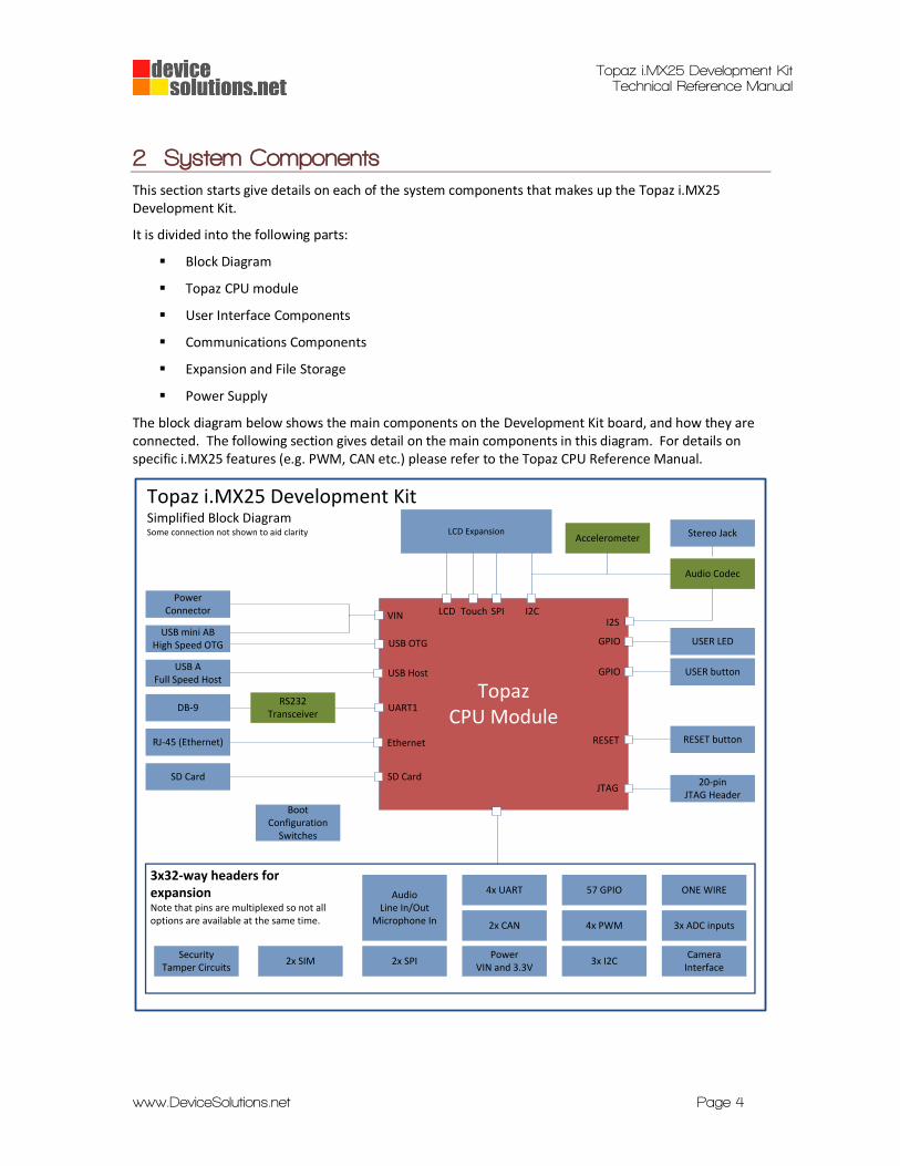
The block diagram below shows the main components on the Development Kit board, and how they are connected. The following section gives detail on the main components in this diagram. For details on specific i.MX25 features (e.g. PWM, CAN etc.) please refer to the Topaz CPU Reference Manual.
LCD ExpansionAccelerometer
Topaz CPU Module
USB OTG
LCDI2S
I2C
SD Card
RESET
GPIO
SD Card
RJ-45 (Ethernet)
Topaz i.MX25 Development KitSimplified Block DiagramSome connection not shown to aid clarity
RESET button
JTAG
BootConfiguration
Switches
PowerConnector VIN
Audio Codec
USB AFull Speed Host
USB mini ABHigh Speed OTG
USER button
USER LED
Touch SPI
Ethernet
USB Host
20-pinJTAG Header
3x32-way headers for expansionNote that pins are multiplexed so not all options are available at the same time. 3x ADC inputs4x PWM2x CAN
4x UARTAudio Line In/Out
Microphone In
CameraInterface
SecurityTamper Circuits
2x SPI 3x I2C
57 GPIO ONE WIRE
PowerVIN and 3.3V
2x SIM
Stereo Jack
UART1DB-9RS232
Transceiver
GPIO
Topaz i.MX25 Development Kit Technical Reference Manual
www.DeviceSolutions.net Page 5
2.1 TOPAZ CPU MODULE
The Topaz CPU Module is at the core of the Topaz Development Kit. The Topaz includes a Freescale i.M25 processor, 64Mbytes of SDRAM and 128Mbytes of flash, a power management chip, and Ethernet PHY.
The block diagram illustrates how the various functions of the Topaz CPU are used in the Development Kit. The i.MX25 has many features, however they are not all available at the same time.
2.2 USER INTERFACE COMPONENTS
2.2.1 LCD and Touch-Screen
The Topaz CPU has an integrated LCD controller and touch-screen controller. The Development Kit LOCD expansion connector includes these signals, along with SPI, I2C and power to enable the connection of a variety of displays. LCD options available include 4.3” and 7” touch screens. You can use the specifications in this document to develop an adapter board to test different displays.
2.2.2 User Button, switches and LED
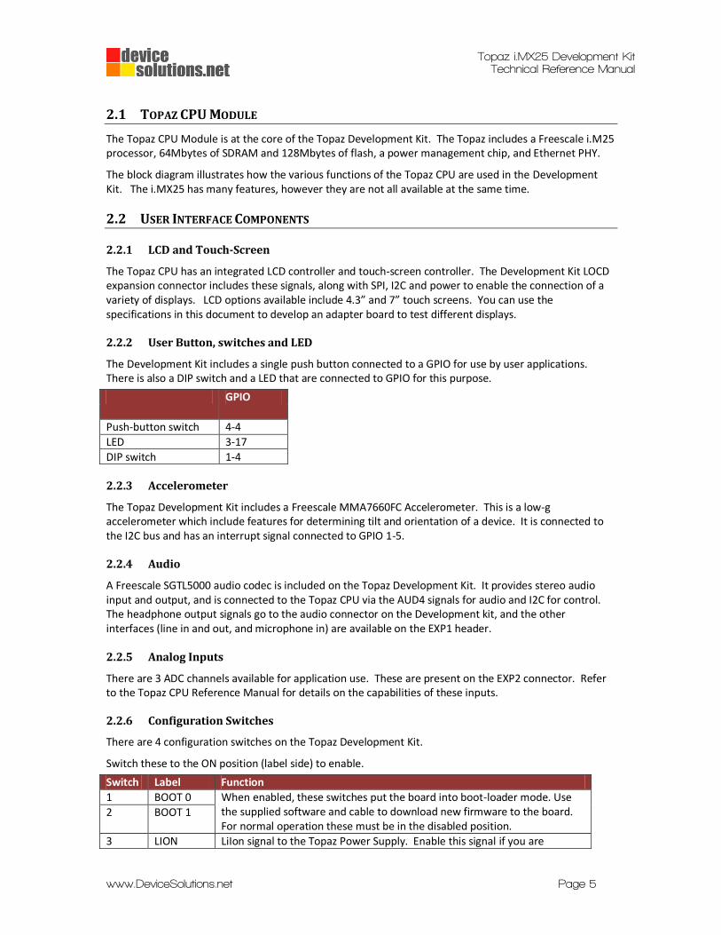
The Development Kit includes a single push button connected to a GPIO for use by user applications. There is also a DIP switch and a LED that are connected to GPIO for this purpose.
GPIO
Push-button switch 4-4
LED 3-17
DIP switch 1-4
2.2.3 Accelerometer
The Topaz Development Kit includes a Freescale MMA7660FC Accelerometer. This is a low-g accelerometer which include features for determining tilt and orientation of a device. It is connected to the I2C bus and has an interrupt signal connected to GPIO 1-5.
2.2.4 Audio
A Freescale SGTL5000 audio codec is included on the Topaz Development Kit. It provides stereo audio input and output, and is connected to the Topaz CPU via the AUD4 signals for audio and I2C for control. The headphone output signals go to the audio connector on the Development kit, and the other interfaces (line in and out, and microphone in) are available on the EXP1 header.
2.2.5 Analog Inputs
There are 3 ADC channels available for application use. These are present on the EXP2 connector. Refer to the Topaz CPU Reference Manual for details on the capabilities of these inputs.
2.2.6 Configuration Switches
There are 4 configuration switches on the Topaz Development Kit.
Switch these to the ON position (label side) to enable.
Switch Label Function
1 BOOT 0 When enabled, these switches put the board into boot-loader mode. Use the supplied software and cable to download new firmware to the board. For normal operation these must be in the disabled position.
2 BOOT 1
3 LION LiIon signal to the Topaz Power Supply. Enable this signal if you are
Topaz i.MX25 Development Kit Technical Reference Manual
www.DeviceSolutions.net Page 6
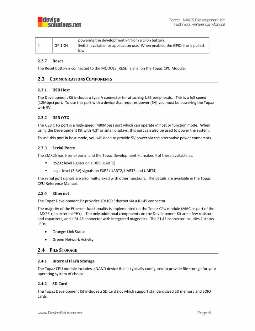
powering the development kit from a LiIon battery.
4 GP 1-04 Switch available for application use. When enabled the GPIO line is pulled low.
2.2.7 Reset
The Reset button is connected to the MODULE_RESET signal on the Topaz CPU Module.
2.3 COMMUNICATIONS COMPONENTS
2.3.1 USB Host
The Development Kit includes a type A connector for attaching USB peripherals. This is a full speed (12Mbps) port. To use this port with a device that requires power (5V) you must be powering the Topaz with 5V.
2.3.2 USB OTG
The USB OTG port is a high-speed (480Mbps) port which can operate in host or function mode. When using the Development Kit with 4.3” or small displays, this port can also be used to power the system.
To use this port in host mode, you will need to provide 5V power via the alternative power connectors.
2.3.3 Serial Ports
The i.MX25 has 5 serial ports, and the Topaz Development Kit makes 4 of these available as:
RS232 level signals on a DB9 (UART1)
Logic level (3.3V) signals on EXP2 (UART2, UART3 and UART4)
The serial port signals are also multiplexed with other functions. The details are available in the Topaz CPU Reference Manual.
2.3.4 Ethernet
The Topaz Development kit provides 10/100 Ethernet via a RJ-45 connector.
The majority of the Ethernet functionality is implemented on the Topaz CPU module (MAC as part of the i.MX25 + an external PHY). The only additional components on the Development Kit are a few resistors and capacitors, and a RJ-45 connector with integrated magnetics. The RJ-45 connector includes 2 status LEDs.
Orange: Link Status
Green: Network Activity
2.4 FILE STORAGE
2.4.1 Internal Flash Storage
The Topaz CPU module includes a NAND device that is typically configured to provide file storage for your operating system of choice.
2.4.2 SD Card
The Topaz Development Kit includes a SD card slot which support standard sized SD memory and SDIO cards.
Topaz i.MX25 Development Kit Technical Reference Manual
www.DeviceSolutions.net Page 7
2.5 EXPANSION
The primary functions of the i.MX25 have been included on dedicated connectors, with the remaining pins made available on 0.1” headers. These are labelled EXP1, EXP2 and EXP3. The Topaz CPU Reference Manual is the best place to look for specific details on each function. The primary use has been labelled on the Topaz Development Board, however most signals can be used for more than one purpose.
When attaching to the EXP connectors, be aware that some signals are 1.8V only.
2.6 POWER SUPPLY
The Topaz Development Kit can be powered from:
USB mini-AB connector.
Barrel connector (J12)
2 pin header (J13)
The Topaz Development Kit will function with voltages ranging from 2.7 to 5.5V. A protection circuit is included to prevent higher voltages from damaging the board.
We recommend that 5V is used whenever possible as this enables the USB Host ports to be used.
2.7 JTAG CONNECTOR
A standard 20-pin ARM JTAG connector is present to allow firmware and application debugging using appropriate tools.
Topaz i.MX25 Development Kit Technical Reference Manual
www.DeviceSolutions.net Page 8
3 Connectors and Signals This section is a reference for all the connectors on the Topaz Development Kit.
It includes:
A summary of all connectors
Pin-out and part number details for each connector
3.1 CONNECTOR SUMMARY
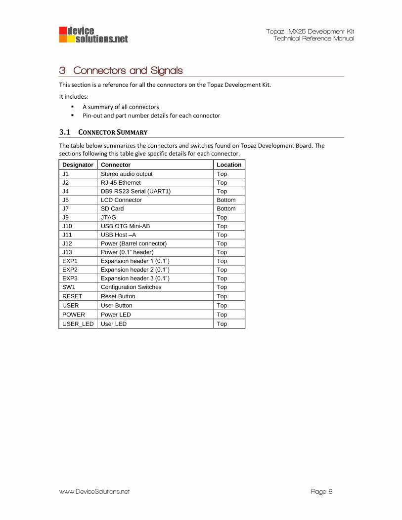
The table below summarizes the connectors and switches found on Topaz Development Board. The sections following this table give specific details for each connector.
Designator Connector Location
J1 Stereo audio output Top
J2 RJ-45 Ethernet Top
J4 DB9 RS23 Serial (UART1) Top
J5 LCD Connector Bottom
J7 SD Card Bottom
J9 JTAG Top
J10 USB OTG Mini-AB Top
J11 USB Host –A Top
J12 Power (Barrel connector) Top
J13 Power (0.1” header) Top
EXP1 Expansion header 1 (0.1”) Top
EXP2 Expansion header 2 (0.1”) Top
EXP3 Expansion header 3 (0.1”) Top
SW1 Configuration Switches Top
RESET Reset Button Top
USER User Button Top
POWER Power LED Top
USER_LED User LED Top
Topaz i.MX25 Development Kit Technical Reference Manual
www.DeviceSolutions.net Page 9
3.2 CONNECTOR DETAILS
3.2.1 Power (J10, J12 and J13)
The Topaz Development Kit can be powered by:
J10 - USB Mini-AB connector
J12 – 2.1mm Barrel connector (centre positive)
J13 – 0.1” pitch header (+5V and 0V).
Not that powering the board via USB may not be sufficient for large LCDs (greater than 4.3”) or if you have devices attached to the expansion connectors or USB host port.
Note that J13 is not fitted to the board. This allows a polarized connector of your choice to be used.
3.2.2 RS232 Serial (J4)
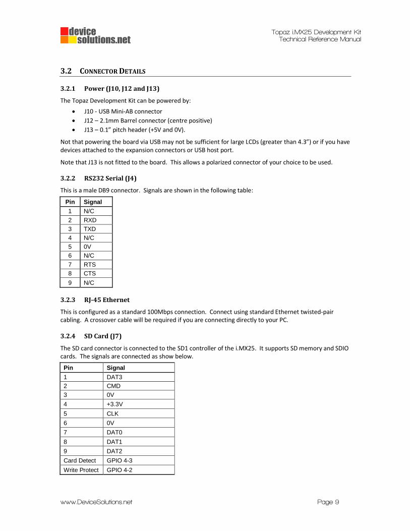
This is a male DB9 connector. Signals are shown in the following table:
Pin Signal
1 N/C
2 RXD
3 TXD
4 N/C
5 0V
6 N/C
7 RTS
8 CTS
9 N/C
3.2.3 RJ-45 Ethernet
This is configured as a standard 100Mbps connection. Connect using standard Ethernet twisted-pair cabling. A crossover cable will be required if you are connecting directly to your PC.
3.2.4 SD Card (J7)
The SD card connector is connected to the SD1 controller of the i.MX25. It supports SD memory and SDIO cards. The signals are connected as show below.
Pin Signal
1 DAT3
2 CMD
3 0V
4 +3.3V
5 CLK
6 0V
7 DAT0
8 DAT1
9 DAT2
Card Detect GPIO 4-3
Write Protect GPIO 4-2
Topaz i.MX25 Development Kit Technical Reference Manual
www.DeviceSolutions.net Page 10
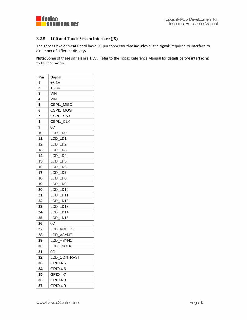
3.2.5 LCD and Touch Screen Interface (J5)
The Topaz Development Board has a 50-pin connector that includes all the signals required to interface to a number of different displays.
Note: Some of these signals are 1.8V. Refer to the Topaz Reference Manual for details before interfacing to this connector.
Pin Signal
1 +3.3V
2 +3.3V
3 VIN
4 VIN
5 CSPI1_MISO
6 CSPI1_MOSI
7 CSPI1_SS3
8 CSPI1_CLK
9 0V
10 LCD_LD0
11 LCD_LD1
12 LCD_LD2
13 LCD_LD3
14 LCD_LD4
15 LCD_LD5
16 LCD_LD6
17 LCD_LD7
18 LCD_LD8
19 LCD_LD9
20 LCD_LD10
21 LCD_LD11
22 LCD_LD12
23 LCD_LD13
24 LCD_LD14
25 LCD_LD15
26 0V
27 LCD_ACD_OE
28 LCD_VSYNC
29 LCD_HSYNC
30 LCD_LSCLK
31 0C
32 LCD_CONTRAST
33 GPIO 4-5
34 GPIO 4-6
35 GPIO 4-7
36 GPIO 4-8
37 GPIO 4-9

Topaz i.MX25 Development Kit Technical Reference Manual
www.DeviceSolutions.net Page 11
38 GPIO 4-10
39 GPIO 4-11
40 GPIO 4-12
41 I2C1_DAT
42 I2C1_CLK
43 0V
44 TOUCH_XN
45 TOUCH_XP
46 TOUCH_YN
47 TOUCH_YP
48 0V
49 VLED_FB
50 VLED
3.2.6 Configuration Switches (SW1)
Details on the Configuration Switches can be found in section 2.2.6.
3.2.7 Expansion Headers (EXP1, EXP2 and EXP3)
The Topaz Development Board has 3 general purpose expansion headers. These expose signals from the Topaz module that are not used directly on the Development Board.
Each signal is labelled on the Development Board.
Note that some signals are 1.8V.
EXP1 EXP2
Pin Signal Pin Signal Pin Signal Pin Signal
1 0V 2 0V 1 I2C1_CLK 2 PWM1
3 +3.3V 4 +3.3V 3 I2C1_DAT 4 PWM2
5 AudioLineIn-L 6 SPI1_MISO 5 ONE_WIRE 6 PWM3
7 AudioLineIn-R 8 SPI1_MOSI 7 CLKO 8 CAN_TXD
9 AudioLineOut-L 10 SPI1_RDY 9 0V 10 CAN_RXD
11 AudioLineOut-R 12 SPI1_CLK 11 ADC_REF 12 UART4_RXD
13 AudioMicIn 14 SPI1_SS0 13 ADC_AUX0 14 UART4_TXD
15 0V 16 SPI1_SS1 15 ADC_AUX1 16 UART4_CTS
17 0V 18 SPI1_SS3 17 ADC_AUX2 18 UART4_RTS
19 SIM1_CLK 20 SIM2_CLK 19 UART2_CTS 20 UART3_RXD
21 SIM1_RST 22 SIM2_RST 21 UART2_RTS 22 UART3_TXD
23 SIM1_VEN 24 SIM2_VEN 23 UART2_RXD 24 UART3_CTS
25 SIM1_TX 26 SIM2_TX 25 UART2_TXD 26 UART3_RTS
27 SIM1_PD 28 SIM2_PD 27 MODULE_RESET 28 +3.3V
29 SIM1_RX 30 SIM2_RX 29 VIN 30 VIN
31 GP 3-23 32 GP3-24 31 0V 32 0V
EXP3
Pin Signal Pin Signal
1 0V 2 0V
3 +3.3V 4 +3.3V
Topaz i.MX25 Development Kit Technical Reference Manual
www.DeviceSolutions.net Page 12
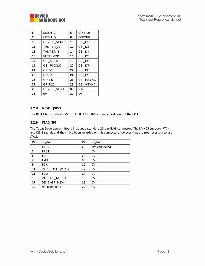
5 MESH_C 6 GP 3-19
7 MESH_D 8 ON/OFF
9 DRYICE_VOUT 10 CSI_D2
11 TAMPER_A 12 CSI_D3
13 TAMPER_B 14 CSI_D4
15 FUSE_VDD 16 CSI_D5
17 CSI_MCLK 18 CSI_D6
19 CSI_PIXCLK 20 CSI_D7
21 GP 3-15 22 CSI_D8
23 GP 3-16 24 CSI_D9
25 GP 1-5 26 CSI_HSYNC
27 GP 2-20 28 CSI_VSYNC
29 DRYICE_VBAT 30 VIN
31 0V 32 0V
3.2.8 RESET (SW3)
The RESET button shorts MODULE_RESET to 0V causing a hard reset of the CPU.
3.2.9 JTAG (J9)
The Topaz Development Board includes a standard 20-pin JTAG connector. The i.MX25 supports RTCK and DE_B signals and they have been included on this connector, however they are not necessary to use JTAG.
Pin Signal Pin Signal
1 +3.3V 2 Not connected
3 TRST 4 0V
5 TDI 6 0V
7 TMS 8 0V
9 TCK 10 0V
11 RTCK (ONE_WIRE) 12 0V
13 TDO 14 0V
15 MODULE_RESET 16 0V
17 DE_B (GP 2-20) 18 0V
19 Not connected 20 0V
Topaz i.MX25 Development Kit Technical Reference Manual
www.DeviceSolutions.net Page 13
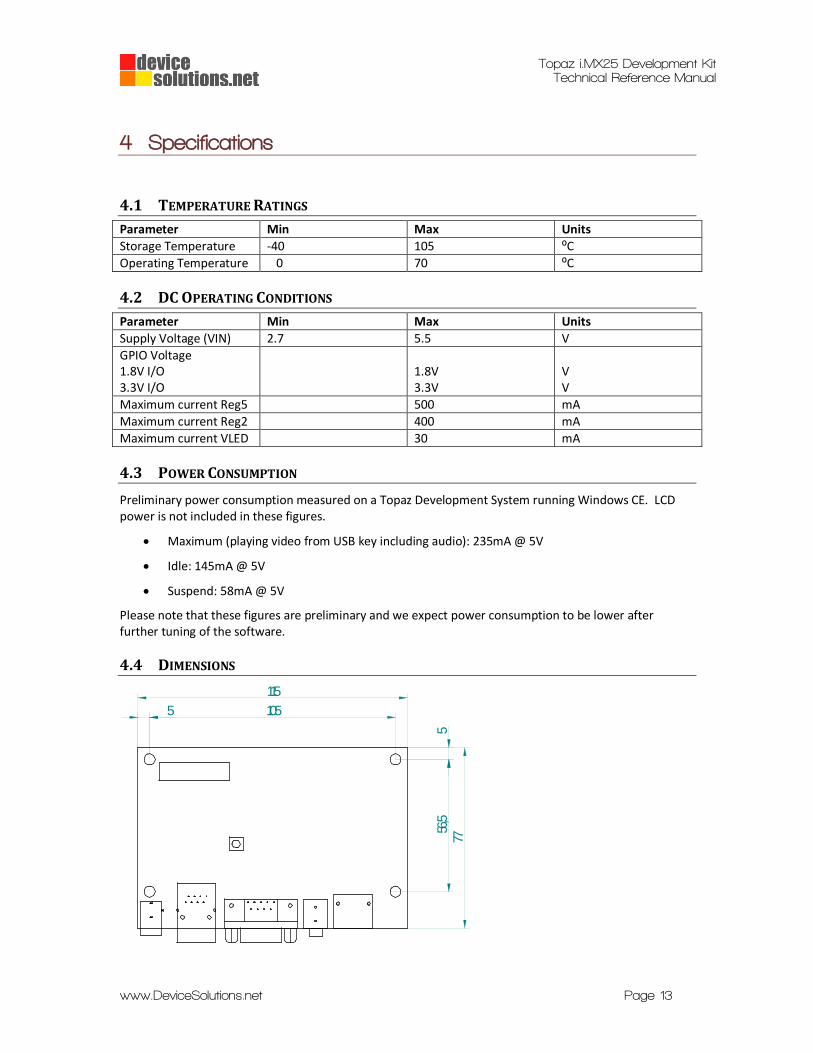
4 Specifications
4.1 TEMPERATURE RATINGS
Parameter Min Max Units
Storage Temperature -40 105 ⁰C
Operating Temperature 0 70 ⁰C
4.2 DC OPERATING CONDITIONS
Parameter Min Max Units
Supply Voltage (VIN) 2.7 5.5 V
GPIO Voltage 1.8V I/O 3.3V I/O
1.8V 3.3V
V V
Maximum current Reg5 500 mA
Maximum current Reg2 400 mA
Maximum current VLED 30 mA
4.3 POWER CONSUMPTION
Preliminary power consumption measured on a Topaz Development System running Windows CE. LCD power is not included in these figures.
Maximum (playing video from USB key including audio): 235mA @ 5V
Idle: 145mA @ 5V
Suspend: 58mA @ 5V
Please note that these figures are preliminary and we expect power consumption to be lower after further tuning of the software.
4.4 DIMENSIONS
115
77
5 105
556
,5