Top View (TV) - led-linear.com · be optionally delivered with the VENUS or PHOBOS product and have...
14
LED Linear™ GmbH I VarioLED™ Flex VENUS, PHOBOS, SKYLLA und NIKE (IP67 & IP68) I All rights reserved, subject to change. I Technical amendments and graphical presentation are subject to change. I 28.02.19 I #33100004 Montageanleitung Installation instructions VarioLED™ Flex VENUS PHOBOS SKYLLA NIKE IP67/68 Top View (TV) Side View (SV) 15 mm 0.59“ 16 mm 0.63“ 10 mm 0.39“ 20,5 mm 0.81“
Transcript of Top View (TV) - led-linear.com · be optionally delivered with the VENUS or PHOBOS product and have...

LED
Line
ar™
Gm
bH I
Var
ioLE
D™ F
lex
VENU
S, P
HOBO
S, S
KYLL
A un
d NI
KE (I
P67
& IP
68)
I All
right
s re
serv
ed, s
ubje
ct to
cha
nge.
I T
echn
ical
am
endm
ents
and
gra
phic
al p
rese
ntat
ion
are
subj
ect t
o ch
ange
. I 2
8.02
.19 I
#33
1000
04
M o n t a g e a n l e i t u n gInstallation instructions
V a r i o L E D ™ F l e x V E N U S P H O B O SS K Y L L AN I K EIP67/68
Top View (TV)
Side View (SV)
15 mm0.59“
16 mm0.63“
10 mm0.39“
20,5 mm0.81“

S. 1
LED
Line
ar™
Gm
bH I
Var
ioLE
D™ F
lex
VENU
S, P
HOBO
S, S
KYLL
A un
d NI
KE (I
P67
& IP
68)
I All
right
s re
serv
ed, s
ubje
ct to
cha
nge.
I T
echn
ical
am
endm
ents
and
gra
phic
al p
rese
ntat
ion
are
subj
ect t
o ch
ange
. I 2
8.02
.19 I
#331
0000
4
Allgemeine HinweiseGeneral information
Achtung: Die Sicherheit der Leuchte wird durch sachgemäße Befolgung nachstehender Anwei-sungen gewährleistet. Bewahren Sie diese Anleitung auch für zukünftige Wartungsarbeiten auf. www.led-linear.de
Warning: The safety of the luminaire is only ensured if the following instructions are followed properly. Keep these instructions for future maintenance work. www.led-linear.com
HINWEISE ZUR MONTAGEInstructions on assembly
Es obliegt dem Verbraucher sicherzustellen, dass eine ausreichende Aufnahme der Lasten gewährleistet ist.Zum Betrieb sollten Netzgeräte verwendet werden, bei denen folgende Schutzmaßnahmen gewährleistet sein müssen: • Kurzschlussschutz • Überlastschutz • Übertemperaturschutz • SELV equiv. (Safety Extra Low Voltage) • Class 2Der Elektrische Anschluss erfolgt immer über eine Steckerbuchse vom Typ VarioCon Female auf der Anschlussseite und dem integrierten Stecker auf der Leuchtenseite.Die Leuchte muss vor der Montage auf Raumtemperatur (18°C – 35°C) gebracht werden. Oberflächen müssen trocken und sauber sein. Oberflächen müssen frei von Staub, Fett, Öl und Trennmittel sein.Lockere Anstriche oder Deckschichten müssen entfernt oder verfestigt werden. Zur Reinigung des Untergrunds nur saubere Tücher unter Verwendung von materialverträglichen Lösemit-teln, wie Benzine, Alkohol, Ester oder Ketone verwenden.Der Anpressdruck beim montieren der Leuchte sollte mit etwa 10 – 15 N/cm2 erfolgen.Bei der Verarbeitung der Produkte, insbesondere großer Längen von über 2 m ist auf eine sorgsame Handhabung der Produkte zu achten, so dass durch unsachgemäße Biegung keine Beschädigung der Leiterbahnen im Produkt erfolgen kann.
SICHERHEITSHINWEISESAFETY INSTRUCTIONS
Die Montage und Wartung darf nur von geschulten Elektrofachkräften mit entsprechender beruflicher Qualifikation in Übereinstimmung mit den neuesten elektrischen Installations- und Sicherheitsvorschriften durchgeführt werden.Es ist zwingend notwendig, vor Beginn jeder Installation, Überprüfung, Wartung oder Reigung, die Netzspannung zu unterbrechen.Für die Installation und für den Betrieb dieser Leuchten sind die nationalen Sicherheitsvor-schriften zu beachten. Der Hersteller übernimmt keine Haftung für Schäden die durchunsach-gemäßen Einsatz oder Montage entstehen.Durch nachträgliche Änderungen an der Leuchte können Zertifikate ihre Gültigkeit verlieren. Zudem gilt somit derjenige als Hersteller, der diese Änderungen vornimmt.Bei Störungen oder Ausfall der Leuchte wenden Sie sich bitte an die LED Linear GmbH.Die maximal zulässige Umgebungstemperatur der Leuchte darf nicht überschritten werden. Überschreitungen reduzieren die Lebensdauer, im Extremfall droht ein Frühausfall.Zum Schutz der sensiblen Oberflächen vor Schmutz und Fingerabdrücken wird empfohlen, während der Montage Schutzhandschuhe zu tragen.Der Transport und die Lagerung der Leuchte müssen in der Originalverpackung erfolgen.Technische und grafische Änderungen vorbehalten.
It is absolutely necessary to isolate the mains supply before beginning any installation, inspec-tion, maintenance or cleaning.Installation and maintenance must be carried out only by trained specialist personnel with appropriate professional qualifications in accordance with the latest electrical installation and safety regulations.Installation and operating of this luminaire are subject to international safety regulations. The manufacturer is not liable for damage caused by improper use or installation.If any luminaire is subsequently modified, certificates can become invalid. The person respon-sible for the modification shall be considered as manufacturer.If malfunctions occur, please directly contact LED Linear GmbH.The maximum admissible ambient temperature of the luminaire may not be exceeded. Surpas-sing that temperature reduces the service life and, in extreme cases, poses risk of early failure.To protect the sensitive surfaces from dirt and fingerprints it is recommended to wear protec-tive gloves during the assembly.The transport and storage of the luminaire must be in the original packaging.Technical amendments and graphical presentation are subject to change.
•
•
•
•
••
•
••
•
•
•
•
••
•
••
•
•
•
••••
••

S. 2
LED
Line
ar™
Gm
bH I
Var
ioLE
D™ F
lex
VENU
S, P
HOBO
S, S
KYLL
A un
d NI
KE (I
P67
& IP
68)
I All
right
s re
serv
ed, s
ubje
ct to
cha
nge.
I T
echn
ical
am
endm
ents
and
gra
phic
al p
rese
ntat
ion
are
subj
ect t
o ch
ange
. I 2
8.02
.19 I
#33
1000
04
Der minimale Biegeradius für alle Top View (TV) und Side View (SV) Produkte von 15 cm darf nicht unterschritten werden.Für eine schnelle und flexible Befestigung der IP67 Produkte sorgt das mitgelieferte Klebeband an der Rückseite der Top View Ausführung. Die Befestigung mittels Klemmen (VarioClip oder VarioContour) ist in jedem Fall vorzuziehen.Für die Side View Produkte ergeben sich drei Möglichkeiten zur Aufbringung des Klebebands. Daher wird das Klebeband optional der Produktlieferung beigestellt und muss vom Kunden aufgebracht werden. Das selbstklebende 3M Klebeband auf der Rückseite der VENUS Leuchte eignet sich nicht für eine freischwebende Überkopf-Verklebung. Bitte nutzen Sie zur zusätzlichen Fixierung VENUS Montage Profil oder VENUS Montage Clip.Zur dauerhaften Befestigung der Produkte empfehlen wir unsere Halteklammern. Die Hal-teklammern sind auch als 2 m lange Profilschienen erhältlich. Bei flachliegender Montage 3 Klammern pro Meter. Bei überkopfmontage 5 Klammern pro Meter. Die IP68 Produkte werden ohne Klebeband ausgeliefert. Hier ist vom Weiterverarbeiter eine sachgemäße Installation vorzunehmen.Temperaturbedingt ergeben sich Längenausdehnungstoleranzen von bis zu +/- 5 mm. In der Breite von +/- 1 mm.Aufgrund der Längenausdehnung darf die Leuchte nicht über den Stoß zweier Montagepro-file installiert werden, um Schereffekte zu vermeiden, welche die Leiterplatte im Inneren der Leuchte beschädigen können. Die Leuchte ist so zu montieren, das die Leuchtenoberfläche mechanisch nicht belastet wird (z.B. im Boden).Bitte beachten Sie zusätzlich die Sicherheits- und Montagehinweise der VarioLED™ Flex Pro-dukte auf Seite 416 ff des LED Linear Systemkatalogs.
It is up to the consumer to ensure that an adequate intake of loads is guaranteed.Power supply units used for operation should ensure the following basic protection and safety features: • Short-Circuit Protection • Overload Protection • Overheat Protection • SELV equivalent (Safety Extra Low Voltage) • Class 2The electrical feed-in is always conducted between a female plug of type VarioCon Female and the fixture-integrated connector.Best temperature for assembly is between +18 ºC and +35 ºC (64 °F to 95 °F)The installation surface must be dry and clean.Surface must be free of dust, grease, oil or separating agents.Lightly adhering coatings must be removed. For cleaning use clean cloth and material-compli-ant detergents like IsopropanolPressure to adhere should be between 10 – 15 N/cm2 (65-97 N / in2).Quick fixation is done by the adhesive on the rear side of the Top View versions. However, the mounting with clamps (VarioClip or VarioContour) is to be preferred in any case.For Side View versions there are 3 options of fixation. Separate reel(s) of adhesive tape will be optionally delivered with the VENUS or PHOBOS product and have to be applied by the customer.The 3M self-adhesive tape on rear side of the VENUS fixture is not suitable for free-floating overhead installations. For additional fixing please use VENUS Mounting Profile or VENUS Mounting clips.As a permanent fixation method our aluminum-clamp VarioClip Venus is recommended. Alu-minum-clamp VarioClip is also available as a profile of 2 m lengths. For flat mounting 3 clips per meter. For overhead mounting 5 clips per meter. IP68 products will be delivered without adhesive. Adequate installation is up to the installer.Due to production, tolerances in linear expansion of up to 5 mm (0.2“) have to be expected. Inwidth by up to +/- 1 mm ( 0,04“).Please ensure that VarioLED™ Flex VENUS is not installed over the joint of 2 profiles to avoidshearing effect which could cause a damage to the FLEX PCB board inside the fixture.While installing the luminaire it must be taken care that after assembling mechanical stress is avoided onto the surface (e.g. mounting into a ground grove).Please notice also safety and assembly information for VarioLED™ Flex, see LED Linear systemCatalog Page 418 ff.
•
•
••
•
•
•
•
•
•
•
•
••••
••
•
•
•
•
•
•
•
S. 3
LED
Line
ar™
Gm
bH I
Var
ioLE
D™ F
lex
VENU
S, P
HOBO
S, S
KYLL
A un
d NI
KE (I
P67
& IP
68)
I All
right
s re
serv
ed, s
ubje
ct to
cha
nge.
I T
echn
ical
am
endm
ents
and
gra
phic
al p
rese
ntat
ion
are
subj
ect t
o ch
ange
. I 2
8.02
.19 I
#331
0000
4
TECHNISCHE DATENTechnical data
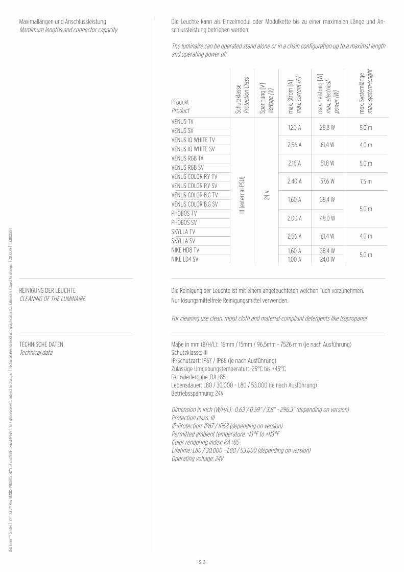
Maße in mm (B/H/L): 16mm / 15mm / 96,5mm – 7526 mm (je nach Ausführung)Schutzklasse: IIIIP-Schutzart: IP67 / IP68 (je nach Ausführung)Zulässige Umgebungstemperatur: -25°C bis +45°CFarbwiedergabe: RA >85Lebensdauer: L80 / 30.000 – L80 / 53.000 (je nach Ausführung)Betriebsspannung: 24V
Dimension in inch (W/H/L): 0,63“/ 0,59“ / 3,8“ – 296.3“ (depending on version)Protection class: IIIIP-Protection: IP67 / IP68 (depending on version)Permitted ambient temperature: -13°F to +113°FColor rendering index: RA >85Lifetime: L80 / 30.000 – L80 / 53.000 (depending on version)Operating voltage: 24V
Die Reinigung der Leuchte ist mit einem angefeuchteten weichen Tuch vorzunehmen.
Nur lösungsmittelfreie Reinigungsmittel verwenden.
For cleaning use clean, moist cloth and material-compliant detergents like Isopropanol.
REINIGUNG DER LEUCHTE CLEANING OF THE LUMINAIRE
Maximallängen und AnschlussleistungMamimum lengths and connector capacity
Die Leuchte kann als Einzelmodul oder Modulkette bis zu einer maximalen Länge und An-schlussleistung betrieben werden:
The luminaire can be operated stand alone or in a chain configuration up to a maximal length and operating power of:
Produkt Product
VENUS TVVENUS SVVENUS IQ WHITE TVVENUS IQ WHITE SVVENUS RGB TAVENUS RGB SVVENUS COLOR R,Y TVVENUS COLOR R,Y SVVENUS COLOR B,G TVVENUS COLOR B,G SVPHOBOS TVPHOBOS SVSKYLLA TVSKYLLA SVNIKE HD8 TVNIKE LD4 SV
Schu
tzkl
asse
Pr
otec
tion
Clas
sIII
(ext
erna
l PSU
)
Span
nung
[V]
Volta
ge [V
]24
V
max
. Lei
stun
g [W
]m
ax. e
lect
rical
po
wer [
W]
1,20 A
2,56 A
2,16 A
2,40 A
1,60 A
2,00 A
2,56 A
1,60 A1,00 A
28,8 W
61,4 W
51,8 W
57,6 W
38,4 W
48,0 W
61,4 W
38,4 W24,0 W
max
. Stro
m [A
]m
ax. c
urre
nt [A
]
max
. Sys
tem
läng
em
ax. s
yste
m-le
nght
5,0 m
4,0 m
5,0 m
7,5 m
5,0 m
4,0 m
5,0 m

S. 4
LED
Line
ar™
Gm
bH I
Var
ioLE
D™ F
lex
VENU
S, P
HOBO
S, S
KYLL
A un
d NI
KE (I
P67
& IP
68)
I All
right
s re
serv
ed, s
ubje
ct to
cha
nge.
I T
echn
ical
am
endm
ents
and
gra
phic
al p
rese
ntat
ion
are
subj
ect t
o ch
ange
. I 2
8.02
.19 I
#33
1000
04
Benötigtes Werkzeug für die Montage der Leuchte :2 PersonenBohrmaschineBohrerSenkerSchraubendreher / ElektroschrauberMetallsäge /Kapp- und Gehrungssäge
Tools required for the installation of luminaire:Two peoplePower drill and drill attachmentSinkerScrewdriver / electric screwdriverHacksaw / miter saw

S. 5
LED
Line
ar™
Gm
bH I
Var
ioLE
D™ F
lex
VENU
S, P
HOBO
S, S
KYLL
A un
d NI
KE (I
P67
& IP
68)
I All
right
s re
serv
ed, s
ubje
ct to
cha
nge.
I T
echn
ical
am
endm
ents
and
gra
phic
al p
rese
ntat
ion
are
subj
ect t
o ch
ange
. I 2
8.02
.19 I
#331
0000
4
15 mm0.59“
16 mm0.63“
Top View (TV)
300 mm / 11,81“
Leuchtfläche / light surface
Leuchtfläche / light surface
Biegerichtung TVBend direction TV
Bitte achten Sie darauf, dass auch bei der Mon-tage NIEMALS die vorgegebene Biegerichtung geändert wird. Das Produkt darf zudem nicht verdreht werden.
VarioLED™ Flex VENUS, PHOBOS, SKYLLA und NIKE dürfen nicht stark gebogen werden. PC-Kern und Verguss können nicht jede Beschädi-gung verhindern.
Der minimale Biegeradius für alle Top View (TV) Produkte von 15 cm darf nicht unterschritten werden.
VarioLED™ Flex VENUS, PHOBOS, SKYLLA und NIKE dürfen nicht: - verdreht werden - fallen gellassen werden - im 90° Winkel bzw. überhaupt geknickt werden - durchhängen / herunterhängen
Please make sure that even during installation the predetermined bending direction is NEVER changed. The product may also not be twisted.
VarioLED™ Flex VENUS, PHOBOS, SKYLLA and NIKE shall not be bent sharply. PC core and en-capsulation can not prevent any damage.
The minimal bending radius for all Top View (TV) products of 15 cm (5.9“) should not be exceeded.
VarioLED™ Flex VENUS, PHOBOS, SKYLLA and NIKE may not be: - Twisted - Dropped - Bent at a 90° angle or bent at all - Sagging / hanging down
•
•
•
•
•
•
•
•

S. 6
LED
Line
ar™
Gm
bH I
Var
ioLE
D™ F
lex
VENU
S, P
HOBO
S, S
KYLL
A un
d NI
KE (I
P67
& IP
68)
I All
right
s re
serv
ed, s
ubje
ct to
cha
nge.
I T
echn
ical
am
endm
ents
and
gra
phic
al p
rese
ntat
ion
are
subj
ect t
o ch
ange
. I 2
8.02
.19 I
#33
1000
04
Biegerichtung SVBend direction SV
Bitte achten Sie darauf, dass auch bei der Mon-tage NIEMALS die vorgegebene Biegerichtung geändert wird. Das Produkt darf zudem nicht verdreht werden.
VarioLED™ Flex VENUS, PHOBOS, SKYLLA und NIKE dürfen nicht stark gebogen werden. PC-Kern und Verguss können nicht jede Beschädi-gung verhindern.
Der minimale Biegeradius für alle Side View (SV) Produkte von 15 cm darf nicht unterschritten werden.
VarioLED™ Flex VENUS, PHOBOS, SKYLLA und NIKE dürfen nicht: - verdreht werden - fallen gellassen werden - im 90° Winkel bzw. überhaupt geknickt werden - durchhängen / herunterhängen
Please make sure that even during installation the predetermined bending direction is NEVER changed. The product may also not be twisted.
VarioLED™ Flex VENUS, PHOBOS, SKYLLA and NIKE shall not be bent sharply. PC core and en-capsulation can not prevent any damage.
The minimal bending radius for all Side View (SV) versions of 15 cm (5.9“) should not be exceeded.
VarioLED™ Flex VENUS, PHOBOS, SKYLLA and NIKE may not be: - Twisted - Dropped - Bent at a 90° angle or bent at all - Sagging / hanging down
10 mm0.39“
20,5 mm0.81“
Side View (SV)
300 mm / 11,81“
Leuchtfläche / light surface
Leuchtfläche / light surface
•
•
•
•
•
•
•
•

S. 7
LED
Line
ar™
Gm
bH I
Var
ioLE
D™ F
lex
VENU
S, P
HOBO
S, S
KYLL
A un
d NI
KE (I
P67
& IP
68)
I All
right
s re
serv
ed, s
ubje
ct to
cha
nge.
I T
echn
ical
am
endm
ents
and
gra
phic
al p
rese
ntat
ion
are
subj
ect t
o ch
ange
. I 2
8.02
.19 I
#331
0000
4
Ihr Leuchtenpaket enthältYour lighting package contains
optionales ZubehörOptinal accessories
VarioLED™ FlexVENUS / PHOBOS / SKYLLA / NIKE TVIP67 (Abbildung: VarioLED™ Flex VENUS TV)(Picture: VarioLED™ Flex VENUS TV)
VarioLED™ FlexVENUS / PHOBOS / SKYLLA / NIKE SVIP67 (Abbildung: VarioLED™ Flex VENUS SV)(Picture: VarioLED™ Flex VENUS TV)
VarioLED™ Flex VENUS / PHOBOS / SKYLLA / NIKETVIP68(Abbildung: VarioLED™ Flex VENUS TV)(Picture: VarioLED™ Flex VENUS TV)
VarioLED™ Flex VENUS / PHOBOS / SKYLLA / NIKESVIP68(Abbildung: VarioLED™ Flex VENUS SV)(Picture: VarioLED™ Flex VENUS SV)
VarioContour VENUS TV/SV2m (78.74“)
VarioClip VENUS TV/SV
VarioCon IP67
VarioPSU
VarioControl
A
B
C
D
F
G
C D
F
A BTV -> Klebeband bereits an der Leuchte befestigtTV -> adhesive tape attached to the luminaire
SV -> Seperates Klebeband für die individuelle Anbringung SV -> Separate adhesive tape for custom fitting
Nur für Leuchten mit max. 2m Länge.Only for luminaire with maximum length of 2m (78.74“)
G
I J
IP67
IP68
H
I
J
H
TV -> Klebeband bereits an der Leuchte befestigtTV -> adhesive tape attached to the luminaire
SV -> Seperates Klebeband für die individuelle Anbringung SV -> Separate adhesive tape for custom fitting

S. 8
LED
Line
ar™
Gm
bH I
Var
ioLE
D™ F
lex
VENU
S, P
HOBO
S, S
KYLL
A un
d NI
KE (I
P67
& IP
68)
I All
right
s re
serv
ed, s
ubje
ct to
cha
nge.
I T
echn
ical
am
endm
ents
and
gra
phic
al p
rese
ntat
ion
are
subj
ect t
o ch
ange
. I 2
8.02
.19 I
#33
1000
04
Schritt für Schritt Anleitung Step by step instructions
Das Paket vorsichtig öffnen.Achten Sie darauf, die Ummantelung des Produk-tes nicht beim Öffnen mit einem scharfen Gegen-stand (Cutter-Messer / Schere) zu beschädigen, da ansonsten kein ausreichender Schutz der Leuchte mehr gewährleistet ist. Bitte überprüfen Sie nach Erhalt die Unversehrt-heit und Vollständigkeit der Ware.
Open the package carefully. Make sure not to damage the encapsulation of the product when opening the package with a sharp object (Cutter Knife / Scissors), otherwise, no ade-quate protection of the LED strip is guaranteed. After receiving the package, please check the in-tegrity and completeness of product.
Die VENUS-Module und das Klebeband bestehen aus verschiedenen Materialien, wie z.B. Polycar-bonat (PC). Um eine sachgemäße Montage zu gewährleisten, müssen diese vor der Montage auf Raumtemperatur gebracht werden. Abhängig vom Lagerort, kann sich bei niedrigen Temperatu-ren die Flexibilität erheblich vermindern.Die Erwärmung auf Raumtemperatur macht die Produkte wieder so flexibel, dass diese optimal montiert werden können.Die günstigste Verarbeitungstemperatur liegt zwischen +18ºC und +35ºC.
The luminaire’s modules and the adhesive tape are made of different materials, such as Polycar-bonate (PC). To ensure proper installation, they must be brought to room temperature before installation. Depending on the storage location, the flexibility of the luminaire can be significantly reduced when temperatures are too low. Warming up to room temperature makes the luminaire fle-xible for proper assembly.The best temperature for assembly is bet-ween +18°C to +35°C (64 ,4°F to 95 °F).
Das Produkt schrittweise und vorsichtig von der Papprundrolle abrollen.Achtung: ab 1m Leuchtenlänge sollte die Montage duch 2 Personen erfolgen!
Unroll the product gradually and carefully from the packing roll. Attention: If the luminaire is longer than 1m (39,37“), the installation should be done by two people.
ab 1m Leuchtenlänge
+35°C (+95°F)bis (to)
+18°C (+64,4°F)
from 39,37“ luminaire length

S. 9
LED
Line
ar™
Gm
bH I
Var
ioLE
D™ F
lex
VENU
S, P
HOBO
S, S
KYLL
A un
d NI
KE (I
P67
& IP
68)
I All
right
s re
serv
ed, s
ubje
ct to
cha
nge.
I T
echn
ical
am
endm
ents
and
gra
phic
al p
rese
ntat
ion
are
subj
ect t
o ch
ange
. I 2
8.02
.19 I
#331
0000
4
Bitte das Produkt immer mit 2 Personen montie-ren (eine Person zum Andrücken, eine Person zum Halten der Papprundrolle).
Bei der Verarbeitung der Produkte, insbesondere großer Längen von über 2 m ist auf eine sorgsa-me Handhabung der Produkte zu achten, so dass durch unsachgemäße Biegung keine Beschädi-gung der Leiterbahnen im Produkt erfolgen kann.
Es ist besonders darauf zu achten, dass kein Teil des Produktes durchhängt bzw. einseitig runter-hängt. Dadurch kann der Biegeradius unterschrit-ten werden und das Produkt großen Schaden nehmen.
The installation of the product should always be carried out by two people. (one person for pres-sing the product onto the surface, one person to hold up the package with the rest of the luminaire)During the installation of the product, especially when the product is longer than 2m (78,74“,) it is important to handle it very careful. Otherwise the conductor tracks in the product can easily be da-maged through improper bending.
It is important to make sure that no part of the product is hanging down. Thereby, the bending radius can be undershot and the product can take extensive damage.
10-15 N / cm2
65-97 N / in2
Anpressdruck
Für eine schnelle und flexible Befestigung der IP67 Produkte sorgt das mitgelieferte Klebeband an der Rückseite der Top View Ausführung.Der Andruck sollte mit etwa 10 – 15 N/cm2 erfolgen.Für die Side View Produkte ergeben sich drei Mög-lichkeiten zur Aufbringung des Klebebands. Daher wird das Klebeband optional der Produktlieferung beigestellt (nicht für freischwebende Überkopf-verklebung geeignet).Die IP68 Produkte werden ohne Klebeband ausge-liefert. Hier ist vom Weiterverarbeiter eine sach-gemäße Installation vorzunehmen.
The attached adhesive tape at the back of the top view version ensures a fast and flexible mounting of the IP67products. The proof should be carried out with about 10-15 N/cm 2 (65-97 N/inch 2).For the side view products, there are three diffe-rent possibilities for applying the adhesive tape (not suitable for freefloating overhead installa-tions). Therefore, the tape is optionally added in the product delivery. The NIKE and the IP68 pro-ducts are delivered without tape. Here it is the processors task to care for a proper installation.

S. 10
LED
Line
ar™
Gm
bH I
Var
ioLE
D™ F
lex
VENU
S, P
HOBO
S, S
KYLL
A un
d NI
KE (I
P67
& IP
68)
I All
right
s re
serv
ed, s
ubje
ct to
cha
nge.
I T
echn
ical
am
endm
ents
and
gra
phic
al p
rese
ntat
ion
are
subj
ect t
o ch
ange
. I 2
8.02
.19 I
#33
1000
04
Zur Befestigung der Produkte empfehlen wir auch unsere Halteklammern. Bei flachliegender Monta-ge werden 3 Klammern pro Meter empfohlen. Bei Überkopf-Montage 5 Klammern pro Meter.As a further fixation method we recommend our aluminum VarioClips. For flat mounting, 3 brackets per meter are recommended. For overhead moun-ting 5 brackets per meter.
VarioClip VENUS TV 50 mm Art.-Nr.: 13000010–01 14,5 mm x 18,5 mm x 50mm (HxBxL)Aluminium (Aluminum) VarioClip TV 30 mm 301 Art.-Nr.: 13000033–01 19 mm x 19,5 mm x 30mm (HxBxL) Edelstahl (stainless steel)VarioClip TV 30 mm 316L Art.-Nr.: 13000050-01 19 mm x 21,5 mm X 30mm (HxBxL) Edelstahl (stainless steel)VarioClip VENUS SV 50 mm Art.-Nr.: 13000011–01 20 mm x 12,5 mm x 50mm (HxBxL) Aluminium (Aluminum)VarioClip SV 30 mm 301 Art.-Nr.: 13000038 24 mm x 15 mm x 30mm (HxBxL) Edelstahl (stainless steel)VarioClip SV 30 mm 316L Art.-Nr.: 13000051-01 26 mm x 16,5 mm x 30mm (HxBxL) Edelstahl (stainless steel)
Die Halteklammern sind auch als 2 m lange Profil-schiene erhältlich.The holding clips are also available as a profile of 2m (78.74“) length.
2 m / 78.74 “
Top View Side View
Clip 50 mm Clip 50 mm
Clip 30 mm (316L) Clip 30 mm (316L)
Clip 30 mm (301) Clip 30 mm (301)
2 m / 78.74 “Montage Profil 2 m
Profile mounting 2m (78.74“)Montage Profil 2 m
Profile mounting 2m (78.74“)
•
•
•
•
•
•
Die Leuchten dürfen nicht über den Stoß zweier Montageprofile installiert werden, um Schereffek-te zu vermeiden, welche die Leiterplatte im Inne-ren der Leuchte beschädigen können.
Thermische Längenausdehnung beachten!Bei der Montage ausreichend Dehnungsfugen zwi-schen den Leuchten vorsehen.Die thermische Längenausdehnung der Leuchte beträgt bei einer Temperaturdifferenz von 10° etwa 1 mm pro Meter.
The luminaire must not be installed over the joint of two mounting profiles, in order to avoid shear effects that can damage the circuit board inside the luminaire.
Observe thermal expansion!During installation ensure that there are sufficient expansion joints between the luminaires.The thermal expansion of the luminaire is about 1 mm per meter at a temperature difference of 10°.
Leuchte / LampLeuchte / Lamp
Profil / ContourDehnungsfuge / Expansion joint
Leuchte / Lamp
Profil / Contour
2 m4 m
2 m2 m
2 m
2 m2 m

S. 11
LED
Line
ar™
Gm
bH I
Var
ioLE
D™ F
lex
VENU
S, P
HOBO
S, S
KYLL
A un
d NI
KE (I
P67
& IP
68)
I All
right
s re
serv
ed, s
ubje
ct to
cha
nge.
I T
echn
ical
am
endm
ents
and
gra
phic
al p
rese
ntat
ion
are
subj
ect t
o ch
ange
. I 2
8.02
.19 I
#331
0000
4
Clip MontageClip mounting
Profil MontageProfile mounting
Montagearten: Clips + Profilmounting type: Clips + profile
Für die Aufnahme einer Senkkopfschraube die Bohrung des Clips „Clip 50mm“ senken.Den Clip mit einer geeigneten Senkkopfschraube am Untergrund befestigen (je nach Untergrund muss dieser ggf. für die Aufnahme der Schraube vorbereitet werden).Lower the hole of the clip „clip 50mm“ to record a countersunk screw.Attach the clip with a suitable countersunk screw to the surface (depending on the surface it must be prepared for receiving the screw).
Das Montageprofil, mit einer Metallsäge auf die gewünschte Länge zu sägen.Mit einem Metallbohrer, für die Befestigung des Profils, ausreichend Löcher vorbohren.Die vorgebohrten Löcher für die Aufnahme einer Senkkopfschraube mit einem Senker senken.Das Profil mit einer geeigneten Senkkopfschraube am Untergrund befestigen (je nach Untergrund muss dieser ggf. für die Aufnahme der Schraube vorbereitet werden).Cut the mounting profile to the desired length with a hacksaw.With a metal drill, pre-drill adequate holes for mounting the profile.Lower the pre-drilled holes with a sinker for recei-ving a countersunk screw.Attach the profile with a suitable countersunk screw to the surface (depending on the surface it must be prepared for receiving the screw).
1 2
1 2
3 4
Die Montageclpis „Clip 30mm (301)“ und „Clip 30mm (316L) sind nicht für eine Montage mit Senkkopfschrauben ausgelegt. Diese können die Montageclips beschädigen.Es wird empfohlen, die Montageclips „Clip 50mm“ mit Senkkopfschrauben zu montieren. Hierfür muss zuvor das vorgebohrte Loch gesenkt werden.The mounting clips „Clip 30mm (301)“ and „Clip 30mm (316L) are not designed for an assembly with countersunk screws. This can damage mounting clips.It is recommended to assemble the mounting clips „Clip 50mm“ with countersunk screws. For this purpose the predrilled hole has to be lowered before.
•
•
•
•
•
•
•
•
•
•
•
•
•
•
•
•

S. 12
LED
Line
ar™
Gm
bH I
Var
ioLE
D™ F
lex
VENU
S, P
HOBO
S, S
KYLL
A un
d NI
KE (I
P67
& IP
68)
I All
right
s re
serv
ed, s
ubje
ct to
cha
nge.
I T
echn
ical
am
endm
ents
and
gra
phic
al p
rese
ntat
ion
are
subj
ect t
o ch
ange
. I 2
8.02
.19 I
#33
1000
04
Bei der Montage mit Profil muss die Leuchte schrittweise ins Profil eingedrückt werden. Die Zeichnung zeigt die verschiedenen Schritte.
When using the mounting profile, the luminaire must be gradually pressed into the profile. The drawing shows the various steps.
ProfilContour
LeuchteLuminaire

LED
Line
ar™
Gm
bH I
Var
ioLE
D™ F
lex
VENU
S, P
HOBO
S, S
KYLL
A un
d NI
KE (I
P67
& IP
68)
I All
right
s re
serv
ed, s
ubje
ct to
cha
nge.
I T
echn
ical
am
endm
ents
and
gra
phic
al p
rese
ntat
ion
are
subj
ect t
o ch
ange
. I 2
8.02
.19 I
#331
0000
4
LED Linear™ GmbHPascalstraße 947506 Neukirchen-VluynGermany
Phone +49 2845 98462-0Fax +49 2845 98462-120Mail [email protected] www.led-linear.com