TOOLS NEWS B140A-F · 2 112 ITEMS.079"–.250" 2.00mm–6.35mm P7 9 ITEMS For finishing, O-ring and...
34
TOOL NEWS FLASH Grooving System GY Series New CBN insert expansion Grooving Revolution Diverse tools provide wide range of applications. Holders and blades for recessing Groove width of 8mm Mono block For Swiss style lathes Mono block For external grooving Precision breaker New coated CBN grade Groove width of 1.5mm MF breaker BC8110 GS/GM breaker 2015.9 Update B140A-F
Transcript of TOOLS NEWS B140A-F · 2 112 ITEMS.079"–.250" 2.00mm–6.35mm P7 9 ITEMS For finishing, O-ring and...

TOOL NEWS FLASHGrooving System
GYSeriesNew CBN
insert
expansion
Grooving RevolutionDiverse tools provide wide range of applications.
Holders and blades for recessing Groove width of 8mm
Mono blockFor Swiss style lathes
Mono blockFor external grooving
Precision breaker New coated CBN grade Groove width of 1.5mm
MFbreaker BC8110 GS/GMbreaker
2015.9 Update B140A-F

1
R/L
70ITEMS
R/L
64ITEMS
R/L
44ITEMS
r 3/8" r 10mmr 1/2" r 12mmr 5/8" r 16mmr 3/4" r 12x20mm
P9, P11
r 3/4" r 20mmr 1" r 25mm
P19, P21
20mm×20mm25mm×25mm
P13, P15
Holder for small lathes
For recessing
Insert width .059"– .128" 1.5–3.24mm
Insert width .079"– .250" 2.0–6.35mm
Insert width 2.0–6.35mm
Mono-block type holder with zero offset between the holder and cutting edge
Product offering for the GY Series

2
112ITEMS
.079"–.250"2.00mm–6.35mm
P7
9ITEMS
For finishing, O-ring and Circlip groove
Inserts available for groove widths from 1.5mm to 8mm.
Coated CBN grade
Ground insert for multifunctional machining
BC8110
4 grades
Insert width
MF breaker

3
P M K S H
a
a
● ●
●
●
NX2525
MY5015
VP10RT
VP20RT VP20RT
VP10RT
VP20RT
VP10RT
MY5015
VP20RT
VP10RT
RT9010
BC8110
MB8025
GROOVING SYSTEM
INSERT
A WIDE SELECTION OF INSERTS
INSERT GRADE
Breaker system Selection of groove widths
Different corner radii available
MF Breaker
Note1) VP20RT is the first recommended grade for materials other than hardened steel.Note2) For VP10RT, VP20RT and MY5015, wet cutting is recommended.
Grooving
GUBreaker(For Mild Steel)
GSBreaker(Low feeds)
GMBreaker(Medium feeds)
GFGS(CBN)
For Multifunctional Grooving Copying/Recessing
MFBreaker(G class)
MSBreaker(Low feeds)
MMBreaker(Medium feeds)
BMBreaker
Cutting Off
GUBreaker(For Mild Steel)
GSBreaker(Low feeds)
GMBreaker(Medium feeds)
R/L05-GMBreaker(Medium feeds)
Work MaterialMachining Condition Steel Stainless Steel Cast Iron Heat resistant Alloy / Titanium Alloy Hardened steel
Stable
Machining Condition
Unstable
Efficient chip breaking when cross-feed machining.
Chips are controlled when finish machining.

4
BC8110
BC8110
Peeling of the coating is prevented by improving welding resistance.
Improved wear and chipping resistance.
Improved adhesion to the CBN surface provides increased peeling resistance.
Prevention of welding
TiAlSiN Coating
TiAlN Coating
Newly developed special PVD coating
Coated CBN Grade for Grooving Hardened Steel
Cutting resistanceForces are dispersed in a linear direction can cause sudden fracturing.
Forces are dispersed radially help to prevent sudden fracturing.
Cutting resistance
Conventional
CBN sintered body “Ultra Micro-particle Binder”
Dispersal of the new Ultra Micro-particle Binder in BC8110 prevents linear crack development that can cause sudden fracturing.
The newly developed “Ultra Micro-particle Binder” prevents sudden fracture
Medium Grain CBN
Binder macroparticles
Micro Grain CBN
Longer tool life with a coated CBN grade when grooving hardened steels.
“Ultra Micro-particle Binder”

5
a●
MY5015
RT9010
NX2525
MB8025
GROOVING SYSTEM
BLANK INSERTSBlank inserts for custom grinding
VP20RT (1st Recommendation)
VP10RT (2nd Recommendation)
a PVD coated grade suitable for a wide range of applications. The combination of a special tough cemented carbide substrate with MIRACLE coating provides an excellent balance of wear and fracture resistance.
a MY5015 is a CVD coated grade with excellent wear resistance even at high temperatures. It provides longer tool life when machining cast and ductile cast irons. Also suitable for high speed continuous cutting of steels.
a NX2525, a cermet grade for finish machining of steels and for good surface finishes at lower cutting speeds.
a First recommended grade for titanium alloys. It is not recommended for use on non-ferrous alloys.
a First recommendation for blank inserts is RT9020 due to the tougher carbide substrate that is suitable for a wider range of applications. RT9010 has a harder substrate than RT9020 and is ideal for longer tool life on stable cutting applications. Both grades are recommended to have a coating applied that is suitable for the required application.
aMB8025 is a sintered CBN grade for hardened steel.
a PVD coated grade with a cemented carbide substrate harder than VP20RT. For use on difficult to cut materials and for extending tool life.
Carbide substrate (HRA90.5)
Carbide substrate (HRA92.0)
CVD Coated Carbide
Carbide substrate
* Blank inserts to be ground by customers.
1 Edge Type 2 Edge Type
RT9010/RT9020 for blank insert
MIRACLE Coating
MIRACLE Coating

6
RE±.002"
CW
RE±.002"
L±.004"
CDX
RE±.002"
CW
RE±.002"
L±.004"
CDX
CW
RE±.002"
RE±.002"
L±.004"
CDX
CW
RE±.002"
5°
L±.004"
CDX
CBN CW
RE CDX L
VP10
RT
VP20
RT
MY5
015
NX2
525
RT9
010
RT9
020
BC
8110
MB
8025
GY2M0200D020N-GU a a a D .079 ±.0012 .008 .776 .815GY2M0239E020N-GU a a a E .094 ±.0012 .008 .780 .815GY2M0250E020N-GU a a a E .098 ±.0012 .008 .768 .815GY2M0300F030N-GU a a a F .118 ±.0012 .012 .760 .815GY2M0318F030N-GU a a a F .125 ±.0012 .012 .760 .815GY2M0400G030N-GU a a a G .157 ±.0016 .012 .953 1.010GY2M0475H040N-GU a a a H .187 ±.0016 .016 .953 1.010GY2M0500H040N-GU a a a H .197 ±.0016 .016 .953 1.010GY2M0600J040N-GU a a a J .236 ±.0016 .016 .953 1.010GY2M0635J040N-GU a a a J .250 ±.0016 .016 .953 1.010GY2M0150C010N-GS a a a C .059 ±.0012 .004 .528 .579GY2M0200D020N-GS a a a D .079 ±.0012 .008 .736 .815GY2M0239E020N-GS a a a E .094 ±.0012 .008 .728 .815GY2M0250E020N-GS a a a E .098 ±.0012 .008 .728 .815GY2M0300F020N-GS a a a F .118 ±.0012 .008 .728 .815GY2M0318F020N-GS a a a F .125 ±.0012 .008 .728 .815GY2M0400G020N-GS a a a G .157 ±.0016 .008 .941 1.010GY2M0475H030N-GS a a a H .187 ±.0016 .012 .941 1.010GY2M0500H030N-GS a a a H .197 ±.0016 .012 .945 1.010GY2M0600J030N-GS a a a J .236 ±.0016 .012 .949 1.010GY2M0635J030N-GS a a a J .250 ±.0016 .012 .949 1.010GY2M0800K030N-GS a a K .315 ±.0016 .012 1.146 1.201GY2M0150C020N-GM a a a C .059 ±.0012 .008 .547 .579GY2M0200D020N-GM a a a a D .079 ±.0012 .008 .764 .815GY2M0239E020N-GM a a a a E .094 ±.0012 .008 .764 .815GY2M0250E020N-GM a a a a E .098 ±.0012 .008 .764 .815GY2M0300F030N-GM a a a a F .118 ±.0012 .012 .764 .815GY2M0318F030N-GM a a a a F .125 ±.0012 .012 .764 .815GY2M0400G030N-GM a a a a G .157 ±.0016 .012 .961 1.010GY2M0475H040N-GM a a a a H .187 ±.0016 .016 .957 1.010GY2M0500H040N-GM a a a a H .197 ±.0016 .016 .957 1.010GY2M0600J040N-GM a a a a J .236 ±.0016 .016 .957 1.010GY2M0635J040N-GM a a a a J .250 ±.0016 .016 .957 1.010GY2M0800K050N-GM a a a K .315 ±.0016 .020 1.154 1.201GY2M0200D020R05-GM a a D .079 ±.0012 .008 .768 .819GY2M0200D020L05-GM a a D .079 ±.0012 .008 .768 .819GY2M0250E020R05-GM a a E .098 ±.0012 .008 .768 .820GY2M0250E020L05-GM a a E .098 ±.0012 .008 .768 .820GY2M0300F030R05-GM a a F .118 ±.0012 .012 .768 .821GY2M0300F030L05-GM a a F .118 ±.0012 .012 .768 .821GY2M0400G030R05-GM a a G .157 ±.0016 .012 .965 1.018GY2M0400G030L05-GM a a G .157 ±.0016 .012 .965 1.018GY2M0500H040R05-GM a a H .197 ±.0016 .016 .965 1.022GY2M0500H040L05-GM a a H .197 ±.0016 .016 .965 1.022
*1
INSERTSA
pplic
atio
ns
Geometry Order Number
Stock
Seat Size
Dimensions (inch)Coated Cermet Carbide
Grooving Width Tolerance
For G
roov
ing
/ Cut
ting
off
GU Breaker(For mild steel)
GS Breaker(Low feeds)
GM Breaker(Medium feeds)
For C
uttin
g of
f
R/L05-GM Breaker
Right hand insert shown.
a : Inventory maintained. (10 inserts in one case) (CBN inserts are available in 1 piece in one case.)

7
RE±.002"
RE±.002"
CW
.118"
7°
7° 7°
L
CW
RE±.002"
RE±.002"
L ±.002"
CDX
CW
RE±.002"
RE±.002"
L±.004"
CDX
CBN CW
RE CDX L
VP10
RTVP
20RT
MY5
015
NX25
25
RT90
10RT
9020
BC81
10M
B802
5
GY1G0200D020N-GFGS a a D .079 ±.0012 .008 ─ .815GY1G0239E020N-GFGS a a E .094 ±.0012 .008 ─ .815GY1G0250E020N-GFGS a a E .098 ±.0012 .008 ─ .815GY1G0300F020N-GFGS a a F .118 ±.0012 .008 ─ .815GY1G0318F020N-GFGS a a F .125 ±.0012 .008 ─ .815GY1G0400G020N-GFGS a a G .157 ±.0012 .008 ─ 1.010GY1G0475H020N-GFGS a a H .187 ±.0012 .008 ─ 1.010GY1G0500H020N-GFGS a a H .197 ±.0012 .008 ─ 1.010GY1G0600J020N-GFGS a J .236 ±.0012 .008 ─ 1.010GY2G0200D020N-MF a a a a D .079 ±.0008 .008 .768 .829
*1GY2G0224D015N-MF a a a a D .088 ±.0008 .006 .780 .829GY2G0239E020N-MF a a a a E .094 ±.0008 .008 .756 .829GY2G0250E020N-MF a a a a E .098 ±.0008 .008 .764 .829
*1GY2G0274E020N-MF a a a a E .108 ±.0008 .008 .776 .829GY2G0300F020N-MF a a a a F .118 ±.0008 .008 .768 .829GY2G0300F040N-MF a a a a F .118 ±.0008 .016 .760 .829GY2G0318F020N-MF a a a a F .125 ±.0008 .008 .768 .829GY2G0318F040N-MF a a a a F .125 ±.0008 .016 .760 .829
*1GY2G0324F020N-MF a a a a F .128 ±.0008 .008 .768 .829GY2G0400G020N-MF a a a a G .157 ±.0008 .008 .980 1.022GY2G0400G040N-MF a a a a G .157 ±.0008 .016 .972 1.022GY2G0400G080N-MF a a a a G .157 ±.0008 .031 .957 1.022
*1GY2G0424G020N-MF a a a a G .167 ±.0008 .008 .980 1.022GY2G0475H020N-MF a a a a H .187 ±.0008 .008 .961 1.022GY2G0475H040N-MF a a a a H .187 ±.0008 .016 .953 1.022GY2G0475H080N-MF a a a a H .187 ±.0008 .031 .937 1.022GY2G0500H020N-MF a a a a H .197 ±.0008 .008 .961 1.022GY2G0500H040N-MF a a a a H .197 ±.0008 .016 .953 1.022GY2G0500H080N-MF a a a a H .197 ±.0008 .031 .937 1.022
*1GY2G0524H020N-MF a a a a H .206 ±.0008 .008 .961 1.022GY2G0600J020N-MF a a a a J .236 ±.0008 .008 .961 1.022GY2G0600J040N-MF a a a a J .236 ±.0008 .016 .953 1.022GY2G0600J080N-MF a a a a J .236 ±.0008 .031 .937 1.022
*1GY2G0631J020N-MF a a a a J .248 ±.0008 .008 .961 1.022GY2G0635J020N-MF a a a a J .250 ±.0008 .008 .961 1.022GY2G0635J040N-MF a a a a J .250 ±.0008 .016 .953 1.022GY2G0635J080N-MF a a a a J .250 ±.0008 .031 .937 1.022GY2M0200D020N-MS a a a a D .079 ±.0012 .008 .752 .815GY2M0250E020N-MS a a a a E .098 ±.0012 .008 .752 .815GY2M0300F020N-MS a a a a F .118 ±.0012 .008 .756 .815GY2M0300F040N-MS a a a a F .118 ±.0012 .016 .744 .815GY2M0400G020N-MS a a a a G .157 ±.0016 .008 .953 1.010GY2M0400G040N-MS a a a a G .157 ±.0016 .016 .941 1.010GY2M0500H040N-MS a a a a H .197 ±.0016 .016 .941 1.010GY2M0500H080N-MS a a a a H .197 ±.0016 .031 .925 1.010GY2M0600J040N-MS a a a a J .236 ±.0016 .016 .941 1.010GY2M0600J080N-MS a a a a J .236 ±.0016 .031 .925 1.010GY2M0800K080N-MS a a a K .315 ±.0016 .031 1.122 1.201
GROOVING SYSTEM
INSERTSA
pplic
atio
ns
Geometry Order Number
Stock
Seat Size
Dimensions (inch)Coated Cermet Carbide
Grooving Width Tolerance
For G
roov
ing
Flat Top (For Hardened material)
For M
ultif
unct
iona
l Gro
ovin
g
MF Breaker(Finishing)
MS Breaker(Low feeds)
*1 Groove width corresponding to the circlip.a : Inventory maintained. (10 inserts in one case) (CBN inserts are available in 1 piece in one case.) s : Inventory maintained in Japan.

8
RE±.002"
CW
RE±.002"
L±.004"
CDX
RE±.002"
CW
L±.004"
CDX
CW
RE
RE
L
L
CW
RE
RE
CBN CW
RE CDX L
VP10
RT
VP20
RT
MY5
015
NX2
525
RT9
010
RT9
020
BC
8110
MB
8025
GY2M0200D020N-MM a a a a D .079 ±.0012 .008 .752 .815GY2M0250E020N-MM a a a a E .098 ±.0012 .008 .752 .815GY2M0300F020N-MM a a a a F .118 ±.0012 .008 .752 .815GY2M0300F040N-MM a a a a F .118 ±.0012 .016 .744 .815GY2M0300F080N-MM a a a a F .118 ±.0012 .031 .728 .815GY2M0400G020N-MM a a a a G .157 ±.0016 .008 .949 1.010GY2M0400G040N-MM a a a a G .157 ±.0016 .016 .941 1.010GY2M0400G080N-MM a a a a G .157 ±.0016 .031 .925 1.010GY2M0500H040N-MM a a a a H .197 ±.0016 .016 .941 1.010GY2M0500H080N-MM a a a a H .197 ±.0016 .031 .925 1.010GY2M0600J040N-MM a a a a J .236 ±.0016 .016 .941 1.010GY2M0600J080N-MM a a a a J .236 ±.0016 .031 .925 1.010GY2M0800K080N-MM a a a K .315 ±.0016 .031 1.122 1.201GY2M0800K120N-MM a a a K .315 ±.0016 .047 1.106 1.201GY2M0200D100N-BM a a a a D .079 ±.0012 .039 .768 .815GY2M0250E125N-BM a a a a E .098 ±.0012 .049 .760 .815GY2M0300F150N-BM a a a a F .118 ±.0012 .059 .748 .823GY2M0318F159N-BM a a a a F .125 ±.0012 .063 .744 .823GY2M0400G200N-BM a a a a G .157 ±.0016 .079 .921 1.016GY2M0475H238N-BM a a a a H .187 ±.0016 .094 .902 1.016GY2M0500H250N-BM a a a a H .197 ±.0016 .098 .898 1.016GY2M0600J300N-BM a a a a J .236 ±.0016 .118 .886 1.020GY2M0635J318N-BM a a a a J .250 ±.0016 .125 .878 1.020GY2M0800K400N-BM a a a K .315 ±.0016 .157 1.043 1.213
*2
GY2B0220D020N s s s D .087 ±.0039 .008 ─ .829GY2B0270E020N s s s E .106 ±.0039 .008 ─ .829GY2B0340F020N s s s F .134 ±.0039 .008 ─ .829GY2B0420G020N s s s G .165 ±.0039 .008 ─ 1.024GY2B0520H020N s s s H .205 ±.0039 .008 ─ 1.024GY2B0655J020N s s s J .258 ±.0039 .008 ─ 1.024GY1B0220D020N s s s D .087 ±.0039 .008 ─ .827GY1B0270E020N s s s E .106 ±.0039 .008 ─ .827GY1B0340F020N s s s F .134 ±.0039 .008 ─ .827GY1B0420G020N s s s G .165 ±.0039 .008 ─ 1.020GY1B0520H020N s s s H .205 ±.0039 .008 ─ 1.020GY1B0655J020N s s s J .258 ±.0039 .008 ─ 1.020
App
licat
ions
Geometry Order Number
Stock
Seat Size
Dimensions (inch)Coated Cermet Carbide
Grooving Width Tolerance
For M
ultif
unct
iona
l Gro
ovin
g
MM Breaker(Medium feeds)
For C
opyi
ng /
Rec
essi
ng
BM Breaker
Bla
nk
2 Edge Type
1 Edge Type
*2 Blank inserts to be ground by customers.

9
CDX
CW0
LF
B
LH
CUTDIA
HF H
LH 2
HB
H
LH
CUTDIA
HF H
LH 2
1-1GY2Mooooooooo-GS
-GM GY2Gooooooooo-MFGY2Mooooooooo-GU GY2Mooooooooo-MSGY1Gooooooooo- GF
GS GY2Mooooooooo-MM
GY2Mooooooooo-BM GY2Mooooooooo-GS-GM
GY2Mooooooooo-GUGY2MoooooR/Loo-GM
*3
H B LF LH LH 2 HF HBH
C .059
.433 .866 R GYSRUS06B00-C11 a A .375 .375 4.500 .866 .620 .375 .125L GYSLUS06B00-C11 a A .375 .375 4.500 .866 .620 .375 .125
.512 1.024 R GYSRUS08B00-C13 a B .500 .500 4.500 .866 .620 .500 ─L GYSLUS08B00-C13 a B .500 .500 4.500 .866 .620 .500 ─
.669*1 1.338*2
R GYSRUS10B00-C17 a B .625 .625 4.500 1.063 .638 .625 ─L GYSLUS10B00-C17 a B .625 .625 4.500 1.063 .638 .625 ─R GYSRUS12B00-C17 a B .750 .750 4.500 1.102 .638 .750 ─L GYSLUS12B00-C17 a B .750 .750 4.500 1.102 .638 .750 ─
D.079.088
.433 .866 R GYSRUS06B00-D11 a A .375 .375 4.500 .866 .899 .375 .125L GYSLUS06B00-D11 a A .375 .375 4.500 .866 .899 .375 .125
.512 1.024 R GYSRUS08B00-D13 a B .500 .500 4.500 .866 .899 .500 ─L GYSLUS08B00-D13 a B .500 .500 4.500 .866 .899 .500 ─
.669*1 1.338*2
R GYSRUS10B00-D17 a B .625 .625 4.500 1.063 .918 .625 ─L GYSLUS10B00-D17 a B .625 .625 4.500 1.063 .918 .625 ─R GYSRUS12B00-D17 a B .750 .750 4.500 1.102 .878 .750 ─L GYSLUS12B00-D17 a B .750 .750 4.500 1.102 .878 .750 ─
E.094.098.108
.433 .866 R GYSRUS06B00-E11 a A .375 .375 4.500 .866 .901 .375 .125L GYSLUS06B00-E11 a A .375 .375 4.500 .866 .901 .375 .125
.512 1.024 R GYSRUS08B00-E13 a B .500 .500 4.500 .866 .901 .500 ─L GYSLUS08B00-E13 a B .500 .500 4.500 .866 .901 .500 ─
.669*1 1.338*2
R GYSRUS10B00-E17 a B .625 .625 4.500 1.063 .920 .625 ─L GYSLUS10B00-E17 a B .625 .625 4.500 1.063 .920 .625 ─R GYSRUS12B00-E17 a B .750 .750 4.500 1.102 .880 .750 ─L GYSLUS12B00-E17 a B .750 .750 4.500 1.102 .880 .750 ─
.787*1 1.574*2
R GYSRUS10B00-E20 a B .625 .625 4.500 1.220 .920 .625 ─L GYSLUS10B00-E20 a B .625 .625 4.500 1.220 .920 .625 ─R GYSRUS12B00-E20 a B .750 .750 4.500 1.220 .880 .750 ─L GYSLUS12B00-E20 a B .750 .750 4.500 1.220 .880 .750 ─
F.118.125.128
.512 1.024 R GYSRUS08B00-F13 a B .500 .500 4.500 .866 .903 .500 ─L GYSLUS08B00-F13 a B .500 .500 4.500 .866 .903 .500 ─
.669*1 1.338*2
R GYSRUS10B00-F17 a B .625 .625 4.500 1.063 .925 .625 ─L GYSLUS10B00-F17 a B .625 .625 4.500 1.063 .925 .625 ─R GYSRUS12B00-F17 a B .750 .750 4.500 1.102 .885 .750 ─L GYSLUS12B00-F17 a B .750 .750 4.500 1.102 .885 .750 ─
.787*1 1.574*2
R GYSRUS10B00-F20 a B .625 .625 4.500 1.220 .925 .625 ─L GYSLUS10B00-F20 a B .625 .625 4.500 1.220 .925 .625 ─R GYSRUS12B00-F20 a B .750 .750 4.500 1.220 .885 .750 ─L GYSLUS12B00-F20 a B .750 .750 4.500 1.220 .885 .750 ─
*4
GROOVING SYSTEM
GYSERIES (EXTERNAL GROOVING for Swiss style lathes)
Right hand tool holder shown.
Fig. A Fig. B
00° type holder (Inch)Insert InsertInsert InsertInsert Insert
Insert InsertInsertInsert
a : Inventory maintained.
*1 The maximum groove depth varies according to the insert used. Please refer to the maximum groove depth of inserts on pages 6 to 8.
*2 The maximum cut off diameter (CUTDIA) varies according to the insert used. The cut off diameter is double the maximum groove depth (CDX) of inserts on pages 6 to 8.
*3 Dimensions shown are when the gauge insert is used. If other insert geometries are used then LF, LH and LH 2 values may vary.
*4 The maximum groove depth is limited by the workpiece diameter. For details, please refer to page 25.
Seat Size
CW (inch)
CDX(inch)
CUTDIA(inch) Type Hand
(R/L)
Order NumberFig.
Dimensions (inch) Cutting Mode
Holder Stock Clockwise Counterclockwise
Mono Block
Mono Block
Mono Block
Mono Block
Mono Block
Mono Block
Mono Block
Mono Block
Mono Block
Mono Block
Mono Block
Mono Block
Mono Block
Mono Block
Mono Block
Mono Block
Mono Block
Mono Block
Mono Block

10
CDEF
P6, P7
CW
C .059", 1.50mm a a
D .079", 2.00mm a a a a a
E.094", 2.39mm a a a a
.098", 2.50mm a a a a a
F .118", 3.00mm a a a a a
.125", 3.18mm a a a a
P7, P8
CW
D.079", 2.00mm a a a a
.088", 2.24mm a
E.094", 2.39mm a
.098", 2.50mm a a a a
.108", 2.74mm a
F
.118", 3.00mm a
RE .008" a a a
RE .016" a a a
RE .031" a
.125", 3.18mm a
RE .008" a
RE .016" a
.128", 3.24mm a
a
R
L
GYSR/LUS06B00-o11TKY10R
GYSR/LUS08B00-o13
GYSR/LUS10B00-o18TKY15R
GYSR/LUS12B00-o17
*3
H B LF LH LH 2 HF HBH
C .059
.433 .866 R GYSRUS06B00-C11 a A .375 .375 4.500 .866 .620 .375 .125L GYSLUS06B00-C11 a A .375 .375 4.500 .866 .620 .375 .125
.512 1.024 R GYSRUS08B00-C13 a B .500 .500 4.500 .866 .620 .500 ─L GYSLUS08B00-C13 a B .500 .500 4.500 .866 .620 .500 ─
.669*1 1.338*2
R GYSRUS10B00-C17 a B .625 .625 4.500 1.063 .638 .625 ─L GYSLUS10B00-C17 a B .625 .625 4.500 1.063 .638 .625 ─R GYSRUS12B00-C17 a B .750 .750 4.500 1.102 .638 .750 ─L GYSLUS12B00-C17 a B .750 .750 4.500 1.102 .638 .750 ─
D.079.088
.433 .866 R GYSRUS06B00-D11 a A .375 .375 4.500 .866 .899 .375 .125L GYSLUS06B00-D11 a A .375 .375 4.500 .866 .899 .375 .125
.512 1.024 R GYSRUS08B00-D13 a B .500 .500 4.500 .866 .899 .500 ─L GYSLUS08B00-D13 a B .500 .500 4.500 .866 .899 .500 ─
.669*1 1.338*2
R GYSRUS10B00-D17 a B .625 .625 4.500 1.063 .918 .625 ─L GYSLUS10B00-D17 a B .625 .625 4.500 1.063 .918 .625 ─R GYSRUS12B00-D17 a B .750 .750 4.500 1.102 .878 .750 ─L GYSLUS12B00-D17 a B .750 .750 4.500 1.102 .878 .750 ─
E.094.098.108
.433 .866 R GYSRUS06B00-E11 a A .375 .375 4.500 .866 .901 .375 .125L GYSLUS06B00-E11 a A .375 .375 4.500 .866 .901 .375 .125
.512 1.024 R GYSRUS08B00-E13 a B .500 .500 4.500 .866 .901 .500 ─L GYSLUS08B00-E13 a B .500 .500 4.500 .866 .901 .500 ─
.669*1 1.338*2
R GYSRUS10B00-E17 a B .625 .625 4.500 1.063 .920 .625 ─L GYSLUS10B00-E17 a B .625 .625 4.500 1.063 .920 .625 ─R GYSRUS12B00-E17 a B .750 .750 4.500 1.102 .880 .750 ─L GYSLUS12B00-E17 a B .750 .750 4.500 1.102 .880 .750 ─
.787*1 1.574*2
R GYSRUS10B00-E20 a B .625 .625 4.500 1.220 .920 .625 ─L GYSLUS10B00-E20 a B .625 .625 4.500 1.220 .920 .625 ─R GYSRUS12B00-E20 a B .750 .750 4.500 1.220 .880 .750 ─L GYSLUS12B00-E20 a B .750 .750 4.500 1.220 .880 .750 ─
F.118.125.128
.512 1.024 R GYSRUS08B00-F13 a B .500 .500 4.500 .866 .903 .500 ─L GYSLUS08B00-F13 a B .500 .500 4.500 .866 .903 .500 ─
.669*1 1.338*2
R GYSRUS10B00-F17 a B .625 .625 4.500 1.063 .925 .625 ─L GYSLUS10B00-F17 a B .625 .625 4.500 1.063 .925 .625 ─R GYSRUS12B00-F17 a B .750 .750 4.500 1.102 .885 .750 ─L GYSLUS12B00-F17 a B .750 .750 4.500 1.102 .885 .750 ─
.787*1 1.574*2
R GYSRUS10B00-F20 a B .625 .625 4.500 1.220 .925 .625 ─L GYSLUS10B00-F20 a B .625 .625 4.500 1.220 .925 .625 ─R GYSRUS12B00-F20 a B .750 .750 4.500 1.220 .885 .750 ─L GYSLUS12B00-F20 a B .750 .750 4.500 1.220 .885 .750 ─
SPARE PARTS
Holder Number
Clamp Screw Wrench
CS350990T (Clamp Torque
: 22 lbf-in)
TS4SBL (Clamp Torque
: 31 lbf-in)
Seat Size
CW (inch)
CDX(inch)
CUTDIA(inch) Type Hand
(R/L)
Order NumberFig.
Dimensions (inch) Cutting Mode
Holder Stock Clockwise Counterclockwise
Mono Block
Mono Block
Mono Block
Mono Block
Mono Block
Mono Block
Mono Block
Mono Block
Mono Block
Mono Block
Mono Block
Mono Block
Mono Block
Mono Block
Mono Block
Mono Block
Mono Block
Mono Block
Mono Block
: Gauge insert shown dimensions
Seat Size Insert Number
GYoo0150Coooo−BreakerGYoo0200/0224Doooo−BreakerGYoo0239/0250/0274Eoooo−BreakerGYoo0300/0318/0324Foooo−Breaker
For Grooving/Cutting off
Seat Size
Breaker GU GS GM 05-GM GFGS
Neutral Neutral Neutral Hand Neutral
For Multifunctional Grooving
Seat Size
Breaker MF MS MM BM
Ball nose
Select an Insert

11
CDX
CW0
LF
B
LH
CUTDIA
HF H
LH 2
HB
H
LH
CUTDIA
HF H
LH 2
LH
CUTDIA
HF H
LH 2
1-2GY2Mooooooooo-GS
-GM GY2Gooooooooo-MFGY2Mooooooooo-GU GY2Mooooooooo-MSGY1Gooooooooo- GF
GS GY2Mooooooooo-MM
GY2Mooooooooo-BM GY2Mooooooooo-GS-GM
GY2Mooooooooo-GUGY2MoooooR/Loo-GM
CW(mm)
CDX(mm)
CUTDIA(mm)
*3
H B LF LH LH 2 HF HBH
C 1.50
11 22 R GYSR1010JX00-C11 a A 10 10 120 22 16 10 2L GYSL1010JX00-C11 a A 10 10 120 22 16 10 2
13 26 R GYSR1212JX00-C13 a B 12 12 120 22 16 12 ─L GYSL1212JX00-C13 a B 12 12 120 22 16 12 ─
17*1 34*2 R GYSR1616JX00-C17 a B 16 16 120 27 17 16 ─L GYSL1616JX00-C17 a B 16 16 120 27 17 16 ─
18*1 36*2 R GYSR2012JX00-C18 a C 20 12 120 28 16 20 ─L GYSL2012JX00-C18 a C 20 12 120 28 16 20 ─
D 2.002.24
11 22 R GYSR1010JX00-D11 a A 10 10 120 22 23 10 2L GYSL1010JX00-D11 a A 10 10 120 22 23 10 2
13 26 R GYSR1212JX00-D13 a B 12 12 120 22 23 12 ─L GYSL1212JX00-D13 a B 12 12 120 22 23 12 ─
17 34 R GYSR1616JX00-D17 a B 16 16 120 27 24 16 ─L GYSL1616JX00-D17 a B 16 16 120 27 24 16 ─
18 36 R GYSR2012JX00-D18 a C 20 12 120 28 23 20 ─L GYSL2012JX00-D18 a C 20 12 120 28 23 20 ─
E2.392.502.74
11 22 R GYSR1010JX00-E11 a A 10 10 120 22 23 10 2L GYSL1010JX00-E11 a A 10 10 120 22 23 10 2
13 26 R GYSR1212JX00-E13 a B 12 12 120 22 23 12 ─L GYSL1212JX00-E13 a B 12 12 120 22 23 12 ─
17 34 R GYSR1616JX00-E17 a B 16 16 120 27 24 16 ─L GYSL1616JX00-E17 a B 16 16 120 27 24 16 ─
18 36 R GYSR2012JX00-E18 a C 20 12 120 28 23 20 ─L GYSL2012JX00-E18 a C 20 12 120 28 23 20 ─
F3.003.183.24
11 22 R GYSR1010JX00-F11 a A 10 10 120 22 23 10 2L GYSL1010JX00-F11 a A 10 10 120 22 23 10 2
13 26 R GYSR1212JX00-F13 a B 12 12 120 22 23 12 ─L GYSL1212JX00-F13 a B 12 12 120 22 23 12 ─
17 34 R GYSR1616JX00-F17 a B 16 16 120 27 24 16 ─L GYSL1616JX00-F17 a B 16 16 120 27 24 16 ─
18 36 R GYSR2012JX00-F18 a C 20 12 120 28 23 20 ─L GYSL2012JX00-F18 a C 20 12 120 28 23 20 ─
*4
GROOVING SYSTEM
GYSERIES (EXTERNAL GROOVING for Swiss style lathes)
Right hand tool holder shown.
Fig. A Fig. B
Fig. C
00° type holder (Metric)Insert InsertInsert InsertInsert Insert
Insert InsertInsertInsert
a : Inventory maintained.
*1 The maximum groove depth varies according to the insert used. Please refer to the maximum groove depth of inserts on pages 6 to 8.
*2 The maximum cut off diameter (CUTDIA) varies according to the insert used. The cut off diameter is double the maximum groove depth (CDX) of inserts on pages 6 to 8.
*3 Dimensions shown are when the gauge insert is used. If other insert geometries are used then LF, LH and LH 2 values may vary.
*4 The maximum groove depth is limited by the workpiece diameter. For details, please refer to page 25.
Seat Size Type Hand
(R/L)
Order NumberFig.
Dimensions (mm) Cutting Mode
Holder Stock Clockwise Counterclockwise
Mono Block
Mono Block
Mono Block
Mono Block
Mono Block
Mono Block
Mono Block
Mono Block
Mono Block
Mono Block
Mono Block
Mono Block
Mono Block
Mono Block
Mono Block
Mono Block

12
CDEF
P6, P7
CW
C .059", 1.50mm a a
D .079", 2.00mm a a a a a
E.094", 2.39mm a a a a
.098", 2.50mm a a a a a
F .118", 3.00mm a a a a a
.125", 3.18mm a a a a
P7, P8
CW
D.079", 2.00mm a a a a
.088", 2.24mm a
E.094", 2.39mm a
.098", 2.50mm a a a a
.108", 2.74mm a
F
.118", 3.00mm a
RE 0.2mm a a a
RE 0.4mm a a a
RE 0.8mm a
.125", 3.18mm a
RE 0.2mm a
RE 0.4mm a
.128", 3.24mm a
a
R
L
GYSR/L1010JX00-o11
TKY10RGYSR/L1212JX00-o13
GYSR/L2012JX00-o18
GYSR/L1616JX00-o17 TKY15R
CW(mm)
CDX(mm)
CUTDIA(mm)
*3
H B LF LH LH 2 HF HBH
C 1.50
11 22 R GYSR1010JX00-C11 a A 10 10 120 22 16 10 2L GYSL1010JX00-C11 a A 10 10 120 22 16 10 2
13 26 R GYSR1212JX00-C13 a B 12 12 120 22 16 12 ─L GYSL1212JX00-C13 a B 12 12 120 22 16 12 ─
17*1 34*2 R GYSR1616JX00-C17 a B 16 16 120 27 17 16 ─L GYSL1616JX00-C17 a B 16 16 120 27 17 16 ─
18*1 36*2 R GYSR2012JX00-C18 a C 20 12 120 28 16 20 ─L GYSL2012JX00-C18 a C 20 12 120 28 16 20 ─
D 2.002.24
11 22 R GYSR1010JX00-D11 a A 10 10 120 22 23 10 2L GYSL1010JX00-D11 a A 10 10 120 22 23 10 2
13 26 R GYSR1212JX00-D13 a B 12 12 120 22 23 12 ─L GYSL1212JX00-D13 a B 12 12 120 22 23 12 ─
17 34 R GYSR1616JX00-D17 a B 16 16 120 27 24 16 ─L GYSL1616JX00-D17 a B 16 16 120 27 24 16 ─
18 36 R GYSR2012JX00-D18 a C 20 12 120 28 23 20 ─L GYSL2012JX00-D18 a C 20 12 120 28 23 20 ─
E2.392.502.74
11 22 R GYSR1010JX00-E11 a A 10 10 120 22 23 10 2L GYSL1010JX00-E11 a A 10 10 120 22 23 10 2
13 26 R GYSR1212JX00-E13 a B 12 12 120 22 23 12 ─L GYSL1212JX00-E13 a B 12 12 120 22 23 12 ─
17 34 R GYSR1616JX00-E17 a B 16 16 120 27 24 16 ─L GYSL1616JX00-E17 a B 16 16 120 27 24 16 ─
18 36 R GYSR2012JX00-E18 a C 20 12 120 28 23 20 ─L GYSL2012JX00-E18 a C 20 12 120 28 23 20 ─
F3.003.183.24
11 22 R GYSR1010JX00-F11 a A 10 10 120 22 23 10 2L GYSL1010JX00-F11 a A 10 10 120 22 23 10 2
13 26 R GYSR1212JX00-F13 a B 12 12 120 22 23 12 ─L GYSL1212JX00-F13 a B 12 12 120 22 23 12 ─
17 34 R GYSR1616JX00-F17 a B 16 16 120 27 24 16 ─L GYSL1616JX00-F17 a B 16 16 120 27 24 16 ─
18 36 R GYSR2012JX00-F18 a C 20 12 120 28 23 20 ─L GYSL2012JX00-F18 a C 20 12 120 28 23 20 ─
SPARE PARTS
Holder Number
Clamp Screw Wrench
CS350990T (Clamp Torque
: 22 lbf-in)
TS4SBL (Clamp Torque
: 31 lbf-in)
Seat Size Type Hand
(R/L)
Order NumberFig.
Dimensions (mm) Cutting Mode
Holder Stock Clockwise Counterclockwise
Mono Block
Mono Block
Mono Block
Mono Block
Mono Block
Mono Block
Mono Block
Mono Block
Mono Block
Mono Block
Mono Block
Mono Block
Mono Block
Mono Block
Mono Block
Mono Block
Select an Insert
: Gauge insert shown dimensions
Seat Size Insert Number
GYoo0150Coooo−BreakerGYoo0200/0224Doooo−BreakerGYoo0239/0250/0274Eoooo−BreakerGYoo0300/0318/0324Foooo−Breaker
For Grooving/Cutting off
Seat Size
Breaker GU GS GM 05-GM GFGS
Neutral Neutral Neutral Hand Neutral
For Multifunctional Grooving
Seat Size
Breaker MF MS MM BM
Ball nose

13
CDX
WF
CW
LF
B
LH
CUTDIA
HF H
1-1GY2Mooooooooo-GS
-GM GY2Gooooooooo-MFGY2Mooooooooo-GU GY2Mooooooooo-MSGY1Gooooooooo- GF
GS GY2Mooooooooo-MM
GY2Mooooooooo-BM GY2Mooooooooo-GS-GM
GY2Mooooooooo-GUGY2MoooooR/Loo-GM
*3
H B LF LH HF WF
D .079 .088
.236 .472 R GYQRUS16D00-D06 a 1.000 1.000 6.000 1.417 1.000 1.006L GYQLUS16D00-D06 a 1.000 1.000 6.000 1.417 1.000 1.006
.787 1.575 R GYQRUS16D00-D20 a 1.000 1.000 6.000 1.614 1.000 1.004L GYQLUS16D00-D20 a 1.000 1.000 6.000 1.614 1.000 1.004
E.094 .098 .108
.236 .472 R GYQRUS16D00-E06 a 1.000 1.000 6.000 1.417 1.000 1.008L GYQLUS16D00-E06 a 1.000 1.000 6.000 1.417 1.000 1.008
.787 1.575 R GYQRUS16D00-E20 a 1.000 1.000 6.000 1.614 1.000 1.004L GYQLUS16D00-E20 a 1.000 1.000 6.000 1.614 1.000 1.004
F.118 .125 .128
.236 .472 R GYQRUS16D00-F06 a 1.000 1.000 6.000 1.417 1.000 1.012L GYQLUS16D00-F06 a 1.000 1.000 6.000 1.417 1.000 1.012
.787 1.575 R GYQRUS16D00-F20 a 1.000 1.000 6.000 1.614 1.000 1.010L GYQLUS16D00-F20 a 1.000 1.000 6.000 1.614 1.000 1.010
G .157 .167
.315 .630 R GYQRUS16D00-G08 a 1.000 1.000 6.000 1.614 1.000 1.014L GYQLUS16D00-G08 a 1.000 1.000 6.000 1.614 1.000 1.014
.984 1.969 R GYQRUS16D00-G25 a 1.000 1.000 6.000 1.811 1.000 1.014L GYQLUS16D00-G25 a 1.000 1.000 6.000 1.811 1.000 1.014
H.187 .197 .206
.315 .630 R GYQRUS16D00-H08 a 1.000 1.000 6.000 1.614 1.000 1.014L GYQLUS16D00-H08 a 1.000 1.000 6.000 1.614 1.000 1.014
.984 1.969 R GYQRUS16D00-H25 a 1.000 1.000 6.000 1.811 1.000 1.014L GYQLUS16D00-H25 a 1.000 1.000 6.000 1.811 1.000 1.014
J.236 .248 .250
.315 .630 R GYQRUS16D00-J08 a 1.000 1.000 6.000 1.614 1.000 1.014L GYQLUS16D00-J08 a 1.000 1.000 6.000 1.614 1.000 1.014
.984 1.969 R GYQRUS16D00-J25 a 1.000 1.000 6.000 1.811 1.000 1.014L GYQLUS16D00-J25 a 1.000 1.000 6.000 1.811 1.000 1.014
GROOVING SYSTEM
GYSERIES (EXTERNAL GROOVING)
*1 The maximum groove depth varies according to the insert used. Please refer to the maximum groove depth of inserts on pages 6 to 8.
*2 The maximum cut off diameter (CUTDIA) varies according to the insert used. The cut off diameter is double the maximum groove depth (CDX) of inserts on pages 6 to 8.
*3 Dimensions shown are when the gauge insert is used. If other insert geometries are used then LF, LH, LH 2 and WF values may vary.
*4 The maximum groove depth is limited by the workpiece diameter. For details, please refer to page 25.
Right hand tool holder shown.
(Note 1) For modular blades and holders, please order separately.(Note 2) Please use right hand modular blade for right hand holder and left hand modular
blade for left hand holder.00° type holder (Inch)
Insert InsertInsert InsertInsert Insert
Insert InsertInsertInsert
Seat Size
CW(inch)
CDX(inch)
CUTDIA(inch)
Hand (R/L)
Order Number Dimensions (inch) Cutting Mode
Holder Stock Clockwise Counterclockwise
a : Inventory maintained.
14
a
DEFGHJ
P6, P7
CW
D .079", 2.00 mm a a a a
E.094", 2.39 mm a a a a
.098", 2.50 mm a a a a a
F.118", 3.00 mm a a a a a
.125", 3.18 mm a a a a
G .157", 4.00 mm a a a a a
H.187", 4.75 mm a a a a
.197", 5.00 mm a a a a a
J .236", 6.00 mm a a a
.250", 6.35 mm a a a
P7, P8
CW
D.079", 2.00 mm a a a a
.088", 2.24 mm a
E.094", 2.39 mm a
.098", 2.50 mm a a a a
.108", 2.74 mm a
F.118", 3.00 mm a a a a
.125", 3.18 mm a a
.128", 3.24 mm a
G.157", 4.00 mm a a a a
.167", 4.24 mm a
H.187", 4.75 mm a a
.197", 5.00 mm a a a a
.206", 5.24 mm a
J.236", 6.00 mm a a a a
.248", 6.31 mm a
.250", 6.35 mm a a
q
R
L
*3
H B LF LH HF WF
D .079 .088
.236 .472 R GYQRUS16D00-D06 a 1.000 1.000 6.000 1.417 1.000 1.006L GYQLUS16D00-D06 a 1.000 1.000 6.000 1.417 1.000 1.006
.787 1.575 R GYQRUS16D00-D20 a 1.000 1.000 6.000 1.614 1.000 1.004L GYQLUS16D00-D20 a 1.000 1.000 6.000 1.614 1.000 1.004
E.094 .098 .108
.236 .472 R GYQRUS16D00-E06 a 1.000 1.000 6.000 1.417 1.000 1.008L GYQLUS16D00-E06 a 1.000 1.000 6.000 1.417 1.000 1.008
.787 1.575 R GYQRUS16D00-E20 a 1.000 1.000 6.000 1.614 1.000 1.004L GYQLUS16D00-E20 a 1.000 1.000 6.000 1.614 1.000 1.004
F.118 .125 .128
.236 .472 R GYQRUS16D00-F06 a 1.000 1.000 6.000 1.417 1.000 1.012L GYQLUS16D00-F06 a 1.000 1.000 6.000 1.417 1.000 1.012
.787 1.575 R GYQRUS16D00-F20 a 1.000 1.000 6.000 1.614 1.000 1.010L GYQLUS16D00-F20 a 1.000 1.000 6.000 1.614 1.000 1.010
G .157 .167
.315 .630 R GYQRUS16D00-G08 a 1.000 1.000 6.000 1.614 1.000 1.014L GYQLUS16D00-G08 a 1.000 1.000 6.000 1.614 1.000 1.014
.984 1.969 R GYQRUS16D00-G25 a 1.000 1.000 6.000 1.811 1.000 1.014L GYQLUS16D00-G25 a 1.000 1.000 6.000 1.811 1.000 1.014
H.187 .197 .206
.315 .630 R GYQRUS16D00-H08 a 1.000 1.000 6.000 1.614 1.000 1.014L GYQLUS16D00-H08 a 1.000 1.000 6.000 1.614 1.000 1.014
.984 1.969 R GYQRUS16D00-H25 a 1.000 1.000 6.000 1.811 1.000 1.014L GYQLUS16D00-H25 a 1.000 1.000 6.000 1.811 1.000 1.014
J.236 .248 .250
.315 .630 R GYQRUS16D00-J08 a 1.000 1.000 6.000 1.614 1.000 1.014L GYQLUS16D00-J08 a 1.000 1.000 6.000 1.614 1.000 1.014
.984 1.969 R GYQRUS16D00-J25 a 1.000 1.000 6.000 1.811 1.000 1.014L GYQLUS16D00-J25 a 1.000 1.000 6.000 1.811 1.000 1.014
z
x
z
x
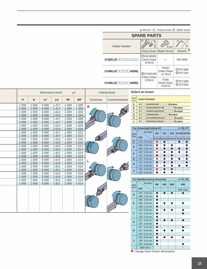
GYQR/LUSooooo-ooo ─ HKY40R
GYHR/LUSooooo-M20R/L zTKY30RxTKY15D
GYHR/LUSooooo-M25R/L zTKY30RxTKY25D
* Wrench : z : Clamp Screw, x : Blade Screw
SPARE PARTS
Holder Number 5 pcs.
Clamp Screw Blade Screw *Wrench
zHSC05030 (Clamp Torque
: 62 lbf-in)
xGY06013M (Clamp Torque
: 53 lbf-in)
TS407 (Clamp Torque
: 31 lbf-in)
TS55 (Clamp Torque
: 44 lbf-in)
Seat Size
CW(inch)
CDX(inch)
CUTDIA(inch)
Hand (R/L)
Order Number Dimensions (inch) Cutting Mode
Holder Stock Clockwise Counterclockwise Seat Size Insert Number
GYoo0200/0224Doooo−BreakerGYoo0239/0250/0274Eoooo−BreakerGYoo0300/0318/0324Foooo−BreakerGYoo0400/0424Goooo−BreakerGYoo0475/0500/0524Hoooo−BreakerGYoo0600/0631/0635Joooo−Breaker
For Grooving/Cutting off
Seat Size
Breaker GU GS GM 05-GM GFGS
Neutral Neutral Neutral Hand Neutral
For Multifunctional Grooving
Seat Size
Breaker MF MS MM BM
Ball nose
Ball nose
Select an Insert
: Gauge insert shown dimensions

15
LH LH
HF HF
H H
HBH
CUTDIACUTDIA
1-2GY2Mooooooooo-GS
-GM GY2Gooooooooo-MFGY2Mooooooooo-GU GY2Mooooooooo-MSGY1Gooooooooo- GF
GS GY2Mooooooooo-MM
GY2Mooooooooo-BM GY2Mooooooooo-GS-GM
GY2Mooooooooo-GUGY2MoooooR/Loo-GM
CW(mm)
CDX(mm)
CUTDIA(mm)
*3
H B LF LH HF WF HBH
D 2.00 2.24
6 12R GYQR2020K00-D06 a G 20 20 125 36 20 20.15 ─L GYQL2020K00-D06 a G 20 20 125 36 20 20.15 ─R GYQR2525M00-D06 a G 25 25 150 36 25 25.15 ─L GYQL2525M00-D06 a G 25 25 150 36 25 25.15 ─
18 36 R GYQR2020K00-D18 a G 20 20 125 39 20 20.10 ─L GYQL2020K00-D18 a G 20 20 125 39 20 20.10 ─
20 40 R GYQR2525M00-D20 a G 25 25 150 41 25 25.15 ─L GYQL2525M00-D20 a G 25 25 150 41 25 25.15 ─
F3.00 3.18 3.24
6 12R GYQR2020K00-F06 a G 20 20 125 36 20 20.30 ─L GYQL2020K00-F06 a G 20 20 125 36 20 20.30 ─R GYQR2525M00-F06 a G 25 25 150 36 25 25.30 ─L GYQL2525M00-F06 a G 25 25 150 36 25 25.30 ─
18 36 R GYQR2020K00-F18 a G 20 20 125 39 20 20.25 ─L GYQL2020K00-F18 a G 20 20 125 39 20 20.25 ─
20 40 R GYQR2525M00-F20 a G 25 25 150 41 25 25.25 ─L GYQL2525M00-F20 a G 25 25 150 41 25 25.25 ─
G 4.00 4.24
8 16R GYQR2020K00-G08 a G 20 20 125 41 20 20.35 ─L GYQL2020K00-G08 a G 20 20 125 41 20 20.35 ─R GYQR2525M00-G08 a G 25 25 150 41 25 25.35 ─L GYQL2525M00-G08 a G 25 25 150 41 25 25.35 ─
25 50R GYQR2020K00-G25 a H 20 20 125 46 20 20.35 4L GYQL2020K00-G25 a H 20 20 125 46 20 20.35 4R GYQR2525M00-G25 a G 25 25 150 46 25 25.35 ─L GYQL2525M00-G25 a G 25 25 150 46 25 25.35 ─
H4.75 5.00 5.24
8 16R GYQR2020K00-H08 a G 20 20 125 41 20 20.35 ─L GYQL2020K00-H08 a G 20 20 125 41 20 20.35 ─R GYQR2525M00-H08 a G 25 25 150 41 25 25.35 ─L GYQL2525M00-H08 a G 25 25 150 41 25 25.35 ─
25 50R GYQR2020K00-H25 a H 20 20 125 46 20 20.35 4L GYQL2020K00-H25 a H 20 20 125 46 20 20.35 4R GYQR2525M00-H25 a G 25 25 150 46 25 25.35 ─L GYQL2525M00-H25 a G 25 25 150 46 25 25.35 ─
J6.00 6.31 6.35
8 16R GYQR2020K00-J08 a G 20 20 125 41 20 20.35 ─L GYQL2020K00-J08 a G 20 20 125 41 20 20.35 ─R GYQR2525M00-J08 a G 25 25 150 41 25 25.35 ─L GYQL2525M00-J08 a G 25 25 150 41 25 25.35 ─
25 50R GYQR2020K00-J25 a H 20 20 125 46 20 20.35 4L GYQR2020K00-J25 a H 20 20 125 46 20 20.35 4R GYQR2525M00-J25 a G 25 25 150 46 25 25.35 ─L GYQL2525M00-J25 a G 25 25 150 46 25 25.35 ─
GROOVING SYSTEM
GYSERIES (EXTERNAL GROOVING)
a : Inventory maintained.
00° type holder (Metric)Insert InsertInsert InsertInsert Insert
Insert InsertInsertInsert
Right hand tool holder shown.
CDX
LF
WF
CW B
Fig. G Fig. H
*1 The maximum groove depth varies according to the insert used. Please refer to the maximum groove depth of inserts on pages 6 to 8.
*2 The maximum cut off diameter (CUTDIA) varies according to the insert used. The cut off diameter is double the maximum groove depth (CDX) of inserts on pages 6 to 8.
*3 Dimensions shown are when the gauge insert is used. If other insert geometries are used then LF, LH, LH 2 and WF values may vary.
(Note 1) For modular blades and holders, please order separately.(Note 2) Please use right hand modular blade for right hand holder and left hand modular
blade for left hand holder.
Seat Size
Hand (R/L)
Order NumberFig.
Dimensions (mm) Cutting Mode
Holder Stock Clockwise Counterclockwise

16
a
DEFGHJ
P6, P7
CW
D .079", 2.00 mm a a a a
E.094", 2.39 mm a a a a
.098", 2.50 mm a a a a a
F.118", 3.00 mm a a a a a
.125", 3.18 mm a a a a
G .157", 4.00 mm a a a a a
H.187", 4.75 mm a a a a
.197", 5.00 mm a a a a a
J .236", 6.00 mm a a a
.250", 6.35 mm a a a
P7, P8
CW
D.079", 2.00 mm a a a a
.088", 2.24 mm a
E.094", 2.39 mm a
.098", 2.50 mm a a a a
.108", 2.74 mm a
F.118", 3.00 mm a a a a
.125", 3.18 mm a a
.128", 3.24 mm a
G.157", 4.00 mm a a a a
.167", 4.24 mm a
H.187", 4.75 mm a a
.197", 5.00 mm a a a a
.206", 5.24 mm a
J.236", 6.00 mm a a a a
.248", 6.31 mm a
.250", 6.35 mm a a
q
R
L
z
x
z
x
GYQR/Looooooo-ooo ─ HKY40R
GYHR/Looooooo-M20R/L zTKY30RxTKY15D
GYHR/Looooooo-M25R/L zTKY30RxTKY25D
CW(mm)
CDX(mm)
CUTDIA(mm)
*3
H B LF LH HF WF HBH
D 2.00 2.24
6 12R GYQR2020K00-D06 a G 20 20 125 36 20 20.15 ─L GYQL2020K00-D06 a G 20 20 125 36 20 20.15 ─R GYQR2525M00-D06 a G 25 25 150 36 25 25.15 ─L GYQL2525M00-D06 a G 25 25 150 36 25 25.15 ─
18 36 R GYQR2020K00-D18 a G 20 20 125 39 20 20.10 ─L GYQL2020K00-D18 a G 20 20 125 39 20 20.10 ─
20 40 R GYQR2525M00-D20 a G 25 25 150 41 25 25.15 ─L GYQL2525M00-D20 a G 25 25 150 41 25 25.15 ─
F3.00 3.18 3.24
6 12R GYQR2020K00-F06 a G 20 20 125 36 20 20.30 ─L GYQL2020K00-F06 a G 20 20 125 36 20 20.30 ─R GYQR2525M00-F06 a G 25 25 150 36 25 25.30 ─L GYQL2525M00-F06 a G 25 25 150 36 25 25.30 ─
18 36 R GYQR2020K00-F18 a G 20 20 125 39 20 20.25 ─L GYQL2020K00-F18 a G 20 20 125 39 20 20.25 ─
20 40 R GYQR2525M00-F20 a G 25 25 150 41 25 25.25 ─L GYQL2525M00-F20 a G 25 25 150 41 25 25.25 ─
G 4.00 4.24
8 16R GYQR2020K00-G08 a G 20 20 125 41 20 20.35 ─L GYQL2020K00-G08 a G 20 20 125 41 20 20.35 ─R GYQR2525M00-G08 a G 25 25 150 41 25 25.35 ─L GYQL2525M00-G08 a G 25 25 150 41 25 25.35 ─
25 50R GYQR2020K00-G25 a H 20 20 125 46 20 20.35 4L GYQL2020K00-G25 a H 20 20 125 46 20 20.35 4R GYQR2525M00-G25 a G 25 25 150 46 25 25.35 ─L GYQL2525M00-G25 a G 25 25 150 46 25 25.35 ─
H4.75 5.00 5.24
8 16R GYQR2020K00-H08 a G 20 20 125 41 20 20.35 ─L GYQL2020K00-H08 a G 20 20 125 41 20 20.35 ─R GYQR2525M00-H08 a G 25 25 150 41 25 25.35 ─L GYQL2525M00-H08 a G 25 25 150 41 25 25.35 ─
25 50R GYQR2020K00-H25 a H 20 20 125 46 20 20.35 4L GYQL2020K00-H25 a H 20 20 125 46 20 20.35 4R GYQR2525M00-H25 a G 25 25 150 46 25 25.35 ─L GYQL2525M00-H25 a G 25 25 150 46 25 25.35 ─
J6.00 6.31 6.35
8 16R GYQR2020K00-J08 a G 20 20 125 41 20 20.35 ─L GYQL2020K00-J08 a G 20 20 125 41 20 20.35 ─R GYQR2525M00-J08 a G 25 25 150 41 25 25.35 ─L GYQL2525M00-J08 a G 25 25 150 41 25 25.35 ─
25 50R GYQR2020K00-J25 a H 20 20 125 46 20 20.35 4L GYQR2020K00-J25 a H 20 20 125 46 20 20.35 4R GYQR2525M00-J25 a G 25 25 150 46 25 25.35 ─L GYQL2525M00-J25 a G 25 25 150 46 25 25.35 ─
* Wrench : z : Clamp Screw, x : Blade Screw
SPARE PARTS
Holder Number 5 pcs.
Clamp Screw Blade Screw *Wrench
zHSC05030 (Clamp Torque
: 62 lbf-in)
xGY06013M (Clamp Torque
: 53 lbf-in)
TS407 (Clamp Torque
: 31 lbf-in)
TS55 (Clamp Torque
: 44 lbf-in)
Seat Size
Hand (R/L)
Order NumberFig.
Dimensions (mm) Cutting Mode
Holder Stock Clockwise Counterclockwise Seat Size Insert Number
GYoo0200/0224Doooo−BreakerGYoo0239/0250/0274Eoooo−BreakerGYoo0300/0318/0324Foooo−BreakerGYoo0400/0424Goooo−BreakerGYoo0475/0500/0524Hoooo−BreakerGYoo0600/0631/0635Joooo−Breaker
For Grooving/Cutting off
Seat Size
Breaker GU GS GM 05-GM GFGS
Neutral Neutral Neutral Hand Neutral
For Multifunctional Grooving
Seat Size
Breaker MF MS MM BM
Ball nose
Ball nose
Select an Insert
: Gauge insert shown dimensions

17
K
P6, P7
CW
K .315", 8.00mm a a
P7, P8
CW
K.315", 8.00mm a
RE .031" a a
RE .047" a
a
CDX
LF
WF CW B
LH LH
HF
HFH
HB
H
H
LH 2 LH 2
CUTDIACUTDIA
CDX
LF
WF
CW B
LH
HF H
LH 2
CUTDIA
1-1GY2Mooooooooo-GS GY2Mooooooooo-MSGY2Mooooooooo-GM GY2Mooooooooo-MM
GY2Mooooooooo-BM GY2Mooooooooo-GSGY2Mooooooooo-GM
GYPR/Looooo00-K25 TKY30R
*3
H B LF LH LH 2 HF WF HBH
K .315 .984 1.968
R GYPRUS16D00-K25 a I 1.000 1.000 6.000 1.850 1.875 1.000 1.161 .260L GYPLUS16D00-K25 a I 1.000 1.000 6.000 1.850 1.875 1.000 1.161 .260R GYPRUS20D00-K25 a K 1.250 1.250 7.000 1.850 2.875 1.250 1.377 ─L GYPLUS20D00-K25 a K 1.250 1.250 7.000 1.850 2.875 1.250 1.377 ─
*3
H B LF LH LH 2 HF WF HBH
K 8.00 25 50
R GYPR2525M00-K25 a I 25 25 150 47 48 25 28 7 L GYPL2525M00-K25 a I 25 25 150 47 48 25 28 7 R GYPR3225P00-K25 a J 32 25 170 47 48 32 28 ─L GYPL3225P00-K25 a J 32 25 170 47 48 32 28 ─R GYPR3232P00-K25 a K 32 32 170 47 48 32 35 ─L GYPL3232P00-K25 a K 32 32 170 47 48 32 35 ─
*1
*1
*2
*2
GROOVING SYSTEM
GYSERIES (EXTERNAL GROOVING)
Right hand tool holder shown.
Fig. I Fig. K
00° type holderInsert InsertInsert Insert
Insert InsertInsert
a : Inventory maintained.
Holder Number
Clamp Screw Wrench
GY06013M (Clamp Torque
: 53 lbf-in)
: Gauge insert shown dimensions
Seat Size Insert Number
GYoo0800Koooo−Breaker
For Grooving/Cutting off
Seat Size
Breaker GU GS GM 05-GM GFGS
Neutral Neutral Neutral Hand Neutral
For Multifunctional Grooving
Seat Size
Breaker MF MS MM BM
Ball nose
*1 The maximum groove depth varies according to the insert used. Please refer to the maximum groove depth of inserts on pages 6 to 8.
*2 The maximum cut off diameter (CUTDIA) varies according to the insert used. The cut off diameter is double the maximum groove depth (CDX) of inserts on pages 6 to 8.
*3 Dimensions shown are when the gauge insert is used. If other insert geometries are used then LF, LH, LH 2 and WF values may vary.
Seat Size
CW(inch)
CDX(inch)
CUTDIA(inch)
Hand (R/L)
Order NumberFig.
Dimensions (inch)
Holder Stock
Seat Size
CW(mm)
CDX(mm)
CUTDIA(mm)
Hand (R/L)
Order NumberFig.
Dimensions (mm)
Holder Stock
SPARE PARTSSelect an Insert
Fig. K

18
Memo
a : Inventory maintained.

19
DM
IN
45°0.5mm
APM
X_2
APMX_2
APMXCDX
LFHF LH
F2
WF
CW
50°
BH
3-1GY2Mooooooooo-BM
*2
H B LF LH HF WF F2
D.079 .088
.020
1.181
.059 .025
R GYHRUS12C50-M20L a GYM20LC-D005 a A .750 .750 5.007 1.632 .750 1.232 .076L GYHLUS12C50-M20R a GYM20RC-D005 a A .750 .750 5.007 1.632 .750 1.232 .076R GYHRUS16D50-M25L a GYM25LC-D005 a A 1.000 1.000 6.007 1.819 1.000 1.357 .076L GYHLUS16D50-M25R a GYM25RC-D005 a A 1.000 1.000 6.007 1.819 1.000 1.357 .076
E.094 .098 .108
.069 .028
R GYHRUS12C50-M20L a GYM20LC-E005 a A .750 .750 5.003 1.628 .750 1.241 .084L GYHLUS12C50-M20R a GYM20RC-E005 a A .750 .750 5.003 1.628 .750 1.241 .084R GYHRUS16D50-M25L a GYM25LC-E005 a A 1.000 1.000 6.003 1.815 1.000 1.366 .084L GYHLUS16D50-M25R a GYM25RC-E005 a A 1.000 1.000 6.003 1.815 1.000 1.366 .084
F.118 .125 .128
.082 .032
R GYHRUS12C50-M20L a GYM20LC-F005 a A .750 .750 5.000 1.625 .750 1.250 .094L GYHLUS12C50-M20R a GYM20RC-F005 a A .750 .750 5.000 1.625 .750 1.250 .094R GYHRUS16D50-M25L a GYM25LC-F005 a A 1.000 1.000 6.000 1.813 1.000 1.375 .094L GYHLUS16D50-M25R a GYM25RC-F005 a A 1.000 1.000 6.000 1.813 1.000 1.375 .094
G.157 .167
.787
.098 .037
R GYHRUS12C50-M20L a GYM20LC-G005 a A .750 .750 4.989 1.614 .750 1.265 .109L GYHLUS12C50-M20R a GYM20RC-G005 a A .750 .750 4.989 1.614 .750 1.265 .109R GYHRUS16D50-M25L a GYM25LC-G005 a A 1.000 1.000 5.989 1.802 1.000 1.390 .109L GYHLUS16D50-M25R a GYM25RC-G005 a A 1.000 1.000 5.989 1.802 1.000 1.390 .109
H.187 .197 .206
.113 .041
R GYHRUS12C50-M20L a GYM20LC-H005 a A .750 .750 4.980 1.605 .750 1.281 .125L GYHLUS12C50-M20R a GYM20RC-H005 a A .750 .750 4.980 1.605 .750 1.281 .125R GYHRUS16D50-M25L a GYM25LC-H005 a A 1.000 1.000 5.980 1.792 1.000 1.406 .125L GYHLUS16D50-M25R a GYM25RC-H005 a A 1.000 1.000 5.980 1.792 1.000 1.406 .125
J.236 .248 .250
.144 .051 R GYHRUS16D50-M25L a GYM25LC-J005 a A 1.000 1.000 5.978 1.791 1.000 1.429 .148L GYHLUS16D50-M25R a GYM25RC-J005 a A 1.000 1.000 5.978 1.791 1.000 1.429 .148
GROOVING SYSTEM
50° type holder (Inch)Insert
Right hand tool holder shown.
(Note 1) For modular blades and holders, please order separately.(Note 2) Please use left hand modular blade for right hand holder and right hand modular
blade for left hand holder.
GYSERIES (EXTERNAL RECESSING)
*1 Blades for external and face grooving cannot be used since it interferes with work materials.
*2 Dimensions shown are when the gauge insert is used. If other insert geometries are used then LF, LH, WF and F2 values may vary.
a : Inventory maintained.
Enlarged view
Fig. A
Seat Size
CW(inch)
CDX(inch)
DMIN(inch)
APMX(inch)
APMX_2(inch) Type Hand
(R/L)
Order NumberFig.
Dimensions (inch)Cutting Mode
Holder Stock Modular Blade Stock
Modular
Modular
Modular
Modular
Modular
Modular
Modular
Modular
Modular
Modular
Modular

20
GY2MooooooooN-BM
P7, P8
CW
D .079", 2.00mm a
E .098", 2.50mm a
F.118", 3.00mm a
.125", 3.18mm a
G .157", 4.00mm a
H.187", 4.75mm a
.197", 5.00mm a
J .236", 6.00mm a
.250", 6.35mm a
a
R
L
z
x
GYHR/LUS12C50-M20R/L zTKY30RxTKY25D
GYHR/LUS16D50-M25R/L zTKY30RxTKY25D
*2
H B LF LH HF WF F2
D.079 .088
.020
1.181
.059 .025
R GYHRUS12C50-M20L a GYM20LC-D005 a A .750 .750 5.007 1.632 .750 1.232 .076L GYHLUS12C50-M20R a GYM20RC-D005 a A .750 .750 5.007 1.632 .750 1.232 .076R GYHRUS16D50-M25L a GYM25LC-D005 a A 1.000 1.000 6.007 1.819 1.000 1.357 .076L GYHLUS16D50-M25R a GYM25RC-D005 a A 1.000 1.000 6.007 1.819 1.000 1.357 .076
E.094 .098 .108
.069 .028
R GYHRUS12C50-M20L a GYM20LC-E005 a A .750 .750 5.003 1.628 .750 1.241 .084L GYHLUS12C50-M20R a GYM20RC-E005 a A .750 .750 5.003 1.628 .750 1.241 .084R GYHRUS16D50-M25L a GYM25LC-E005 a A 1.000 1.000 6.003 1.815 1.000 1.366 .084L GYHLUS16D50-M25R a GYM25RC-E005 a A 1.000 1.000 6.003 1.815 1.000 1.366 .084
F.118 .125 .128
.082 .032
R GYHRUS12C50-M20L a GYM20LC-F005 a A .750 .750 5.000 1.625 .750 1.250 .094L GYHLUS12C50-M20R a GYM20RC-F005 a A .750 .750 5.000 1.625 .750 1.250 .094R GYHRUS16D50-M25L a GYM25LC-F005 a A 1.000 1.000 6.000 1.813 1.000 1.375 .094L GYHLUS16D50-M25R a GYM25RC-F005 a A 1.000 1.000 6.000 1.813 1.000 1.375 .094
G.157 .167
.787
.098 .037
R GYHRUS12C50-M20L a GYM20LC-G005 a A .750 .750 4.989 1.614 .750 1.265 .109L GYHLUS12C50-M20R a GYM20RC-G005 a A .750 .750 4.989 1.614 .750 1.265 .109R GYHRUS16D50-M25L a GYM25LC-G005 a A 1.000 1.000 5.989 1.802 1.000 1.390 .109L GYHLUS16D50-M25R a GYM25RC-G005 a A 1.000 1.000 5.989 1.802 1.000 1.390 .109
H.187 .197 .206
.113 .041
R GYHRUS12C50-M20L a GYM20LC-H005 a A .750 .750 4.980 1.605 .750 1.281 .125L GYHLUS12C50-M20R a GYM20RC-H005 a A .750 .750 4.980 1.605 .750 1.281 .125R GYHRUS16D50-M25L a GYM25LC-H005 a A 1.000 1.000 5.980 1.792 1.000 1.406 .125L GYHLUS16D50-M25R a GYM25RC-H005 a A 1.000 1.000 5.980 1.792 1.000 1.406 .125
J.236 .248 .250
.144 .051 R GYHRUS16D50-M25L a GYM25LC-J005 a A 1.000 1.000 5.978 1.791 1.000 1.429 .148L GYHLUS16D50-M25R a GYM25RC-J005 a A 1.000 1.000 5.978 1.791 1.000 1.429 .148
* Wrench : z : Clamp Screw, x : Blade Screw
SPARE PARTS
Holder Number 5 pcs.
Clamp Screw Blade Screw *Wrench
GY06013M (Clamp Torque
: 53 lbf-in)
TS407 (Clamp Torque
: 31 lbf-in)
TS55 (Clamp Torque
: 44 lbf-in)
: Gauge insert shown dimensions
Insert Number
For Multifunctional Grooving
Seat Size
Breaker BM
Ball nose
Select an Insert
Seat Size
CW(inch)
CDX(inch)
DMIN(inch)
APMX(inch)
APMX_2(inch) Type Hand
(R/L)
Order NumberFig.
Dimensions (inch)Cutting Mode
Holder Stock Modular Blade Stock
Modular
Modular
Modular
Modular
Modular
Modular
Modular
Modular
Modular
Modular
Modular

21
DM
IN
45°0.5mm
APM
X_2
APMX_2
APMXCDX
LFHF LH
F2
WF
CW
50°
BH
3-2GY2Mooooooooo-BM
CW(mm)
CDX(mm)
DMIN(mm)
APMX(mm)
APMX_2(mm)
*2
H B LF LH HF WF F2
D 2.00
0.5
30
1.5 0.646
R GYHR2020K50-M20L a GYM20LC-D005 a A 20 20 125 40 20 32 1.6L GYHL2020K50-M20R a GYM20RC-D005 a A 20 20 125 40 20 32 1.6R GYHR2525M50-M25L a GYM25LC-D005 a A 25 25 150 45 25 35 1.6L GYHL2525M50-M25R a GYM25RC-D005 a A 25 25 150 45 25 35 1.6
E 2.50 1.75 0.72
R GYHR2020K50-M20L a GYM20LC-E005 a A 20 20 125 40 20 32 1.8L GYHL2020K50-M20R a GYM20RC-E005 a A 20 20 125 40 20 32 1.8R GYHR2525M50-M25L a GYM25LC-E005 a A 25 25 150 45 25 35 1.8L GYHL2525M50-M25R a GYM25RC-E005 a A 25 25 150 45 25 35 1.8
F3.00 3.18
2 0.793
R GYHR2020K50-M20L a GYM20LC-F005 a A 20 20 125 40 20 32 2.0L GYHL2020K50-M20R a GYM20RC-F005 a A 20 20 125 40 20 32 2.0R GYHR2525M50-M25L a GYM25LC-F005 a A 25 25 150 45 25 35 2.0L GYHL2525M50-M25R a GYM25RC-F005 a A 25 25 150 45 25 35 2.0
G 4.00
20
2.5 0.939
R GYHR2020K50-M20L a GYM20LC-G005 a A 20 20 125 40 20 32 2.4L GYHL2020K50-M20R a GYM20RC-G005 a A 20 20 125 40 20 32 2.4R GYHR2525M50-M25L a GYM25LC-G005 a A 25 25 150 45 25 35 2.4L GYHL2525M50-M25R a GYM25RC-G005 a A 25 25 150 45 25 35 2.4
H4.75 5.00
2.88 1.049
R GYHR2020K50-M20L a GYM20LC-H005 a A 20 20 125 40 20 33 2.8L GYHL2020K50-M20R a GYM20RC-H005 a A 20 20 125 40 20 33 2.8R GYHR2525M50-M25L a GYM25LC-H005 a A 25 25 150 45 25 36 2.8L GYHL2525M50-M25R a GYM25RC-H005 a A 25 25 150 45 25 36 2.8
J6.00 6.35
3.5 1.232 R GYHR2525M50-M25L a GYM25LC-J005 a A 25 25 150 44 25 36 3.4L GYHL2525M50-M25R a GYM25RC-J005 a A 25 25 150 44 25 36 3.4
GROOVING SYSTEM
50° type holder (Metric)Insert
Right hand tool holder shown.
(Note 1) For modular blades and holders, please order separately.(Note 2) Please use left hand modular blade for right hand holder and right hand modular
blade for left hand holder.
GYSERIES (EXTERNAL RECESSING)
*1 Blades for external and face grooving cannot be used since it interferes with work materials.
*2 Dimensions shown are when the gauge insert is used. If other insert geometries are used then LF, LH, WF and F2 values may vary.
a : Inventory maintained.
Enlarged view
Fig. A
Seat Size Type Hand
(R/L)
Order NumberFig.
Dimensions (mm)Cutting Mode
Holder Stock Modular Blade Stock
Modular
Modular
Modular
Modular
Modular
Modular
Modular
Modular
Modular
Modular
Modular

22
GY2MooooooooN-BM
P7, P8
CW
D .079", 2.00mm a
E .098", 2.50mm a
F.118", 3.00mm a
.125", 3.18mm a
G .157", 4.00mm a
H.187", 4.75mm a
.197", 5.00mm a
J .236", 6.00mm a
.250", 6.35mm a
a
R
L
z
x
GYHR/L2020K50-M20R/L zTKY30RxTKY25D
GYHR/L2525M50-M25R/L zTKY30RxTKY25D
CW(mm)
CDX(mm)
DMIN(mm)
APMX(mm)
APMX_2(mm)
*2
H B LF LH HF WF F2
D 2.00
0.5
30
1.5 0.646
R GYHR2020K50-M20L a GYM20LC-D005 a A 20 20 125 40 20 32 1.6L GYHL2020K50-M20R a GYM20RC-D005 a A 20 20 125 40 20 32 1.6R GYHR2525M50-M25L a GYM25LC-D005 a A 25 25 150 45 25 35 1.6L GYHL2525M50-M25R a GYM25RC-D005 a A 25 25 150 45 25 35 1.6
E 2.50 1.75 0.72
R GYHR2020K50-M20L a GYM20LC-E005 a A 20 20 125 40 20 32 1.8L GYHL2020K50-M20R a GYM20RC-E005 a A 20 20 125 40 20 32 1.8R GYHR2525M50-M25L a GYM25LC-E005 a A 25 25 150 45 25 35 1.8L GYHL2525M50-M25R a GYM25RC-E005 a A 25 25 150 45 25 35 1.8
F3.00 3.18
2 0.793
R GYHR2020K50-M20L a GYM20LC-F005 a A 20 20 125 40 20 32 2.0L GYHL2020K50-M20R a GYM20RC-F005 a A 20 20 125 40 20 32 2.0R GYHR2525M50-M25L a GYM25LC-F005 a A 25 25 150 45 25 35 2.0L GYHL2525M50-M25R a GYM25RC-F005 a A 25 25 150 45 25 35 2.0
G 4.00
20
2.5 0.939
R GYHR2020K50-M20L a GYM20LC-G005 a A 20 20 125 40 20 32 2.4L GYHL2020K50-M20R a GYM20RC-G005 a A 20 20 125 40 20 32 2.4R GYHR2525M50-M25L a GYM25LC-G005 a A 25 25 150 45 25 35 2.4L GYHL2525M50-M25R a GYM25RC-G005 a A 25 25 150 45 25 35 2.4
H4.75 5.00
2.88 1.049
R GYHR2020K50-M20L a GYM20LC-H005 a A 20 20 125 40 20 33 2.8L GYHL2020K50-M20R a GYM20RC-H005 a A 20 20 125 40 20 33 2.8R GYHR2525M50-M25L a GYM25LC-H005 a A 25 25 150 45 25 36 2.8L GYHL2525M50-M25R a GYM25RC-H005 a A 25 25 150 45 25 36 2.8
J6.00 6.35
3.5 1.232 R GYHR2525M50-M25L a GYM25LC-J005 a A 25 25 150 44 25 36 3.4L GYHL2525M50-M25R a GYM25RC-J005 a A 25 25 150 44 25 36 3.4
* Wrench : z : Clamp Screw, x : Blade Screw
SPARE PARTS
Holder Number 5 pcs.
Clamp Screw Blade Screw *Wrench
GY06013M (Clamp Torque
: 53 lbf-in)
TS407 (Clamp Torque
: 31 lbf-in)
TS55 (Clamp Torque
: 44 lbf-in)
Select an Insert
Seat Size Type Hand
(R/L)
Order NumberFig.
Dimensions (mm)Cutting Mode
Holder Stock Modular Blade Stock
Modular
Modular
Modular
Modular
Modular
Modular
Modular
Modular
Modular
Modular
Modular
: Gauge insert shown dimensions
Insert Number
For Multifunctional Grooving
Seat Size
Breaker BM
Ball nose

23
KJHGFED C
KJHGFED C
JHGFED
JHGFED
0 0
0 0 .002 .004 .006
.004
.004
.008
.008
.012
.012
.016
.016
.001 .004 .008
C .059", 1.50mm
D .079", 2.00mm.088", 2.24mm
E.094", 2.39mm.098", 2.50mm.108", 2.74mm
F.118", 3.00mm.125", 3.18mm.128", 3.24mm
G .157", 4.00mm.167", 4.24mm
H.187", 4.75mm.197", 5.00mm.206", 5.24mm
J.236", 6.00mm.248", 6.31mm.250", 6.35mm
K .315", 8.00mm
P VP20RT
VP10RT
NX2525
160─280HB
VP20RT
VP10RT
MY5015
NX2525
VP20RT
VP10RT
MY5015
NX2525
M VP20RT
VP10RT
K VP20RT
VP10RT
MY5015
VP20RT
VP10RT
MY5015
S
─
VP20RT
VP10RT
RT9010
H BC8110/MB8025
165 330 490 655 820 985
330 720
360 755
295 690
260 590
360 820
230 560
195 460
230 490
295 690
180 440
195 460
230 490
260 590
460 985
195 460
230 490
295 690
260 395
130 230
100 195
y
230130
295 620
295 620
GROOVING SYSTEM
RECOMMENDED CUTTING SPEED (SFM) [For External Grooving]
(Note 1) VP20RT is the first recommended grade for materials other than hardened steel.(Note 2) For VP10RT, VP20RT and MY5015, wet cutting is recommended.
Work Material Hardness Grade Cutting Speed (SFM)
Mild Steel <160HB
Carbon SteelAlloy Steel
280HB<
Stainless Steel <270HB
Gray Cast IronTensile Strength
<300MPa
Ductile Cast IronTensile Strength
<800MPa
Heat Resistant AlloyTitanium Alloy
Hardened steel 50HRC<
Seat SizeInsert Width
Sea
t siz
e
RECOMMENDED CUTTING CONDITIONS [For External Grooving]* Below are the recommended cutting conditions when using the modular type holder GYHR/L2525M00/90-M25R/L with the modular blade GYM25R/LA-ooo.
Recommended feed rate and depth of cut
GU BREAKER GS BREAKER
GM BREAKER FLAT TOP GFGS (CBN)
aGrooving, Cutting off aGrooving, Cutting off
aGrooving, Cutting off aGrooving
Feed (IPR) Feed (IPR)
Feed (IPR) Feed (IPR)
Sea
t siz
e
: 1st recommended area
Sea
t siz
e
Sea
t siz
e

24
KJHGFED
KJHGFED
.157
.118
.079
.039
.157
.118
.079
.039
.118
.079
.039
KJHGFED
.118
.098
.079
.059
.039
.020
JHGFED
0 .008.006.004.002
0 .016.012.008.004
0 .016.012.008.004
0 .016.012.008.004
0 .008.006.004.002
0 .016.012.008.004
0 .016.012.008.004
0 .032.024 .028.008 .012 .016 .020.004
.004 .008
US12 100%
80%
60%
50%
US10
US08
US06
J
D
G
FE
H
J
D
GF
H
K
E
J
D
GH
E
K
F
J
D
GH
E
K
F
GYM25 GYM20 GYM20.750
"
.750
"
.625
"
y
C .059", 1.50mm
D .079", 2.00mm.088", 2.24mm
E.094", 2.39mm.098", 2.50mm.108", 2.74mm
F.118", 3.00mm.125", 3.18mm.128", 3.24mm
G .157", 4.00mm.167", 4.24mm
H.187", 4.75mm.197", 5.00mm.206", 5.24mm
J.236", 6.00mm.248", 6.31mm.250", 6.35mm
K .315", 8.00mm
MS BREAKER
MM BREAKER
BM BREAKER
a Turning
a Turning
a Turning
(Note) When using a combination as shown below, decrease the recommended feed rate by 20% and 40% respectively.
a Decrease the feed rate by 20%.
(.750"×.750" Square holder) (.625"×.625" Square holder)
a Decrease the feed rate by 40%.
aGrooving
aGrooving
aGrooving
Sea
t siz
eS
eat s
ize
Sea
t siz
eMF BREAKER
: 1st recommended area
: 1st recommended area
: 1st recommended area
: 1st recommended area
a Turning
Feed (IPR)
Feed (IPR)
Feed (IPR)
Feed (IPR)
Feed (IPR)
Feed (IPR)
Feed (IPR)
Feed (IPR)
Rad
ial D
epth
of c
ut (i
nch)
Rad
ial D
epth
of c
ut (i
nch)
Rad
ial D
epth
of c
ut (i
nch)
Rad
ial D
epth
of c
ut (i
nch)
aGroovingS
eat s
ize
Seat size
Seat size
Seat size
Seat size
Recommended maximum feed rate
Please refer to the tables above of recommended cutting conditions for external grooving. Apply the percentage ratio shown of each shank size to the values in those tables.
For Swiss style lathes mono block holder
Seat SizeInsert Width

25
CDXCDX 2
.433
.394
.354
.315
.276
.236
.197
.157
.118
.079
.039
.669
.630
.591
.551
.512
.472
.433
.394
.354
.315
.276
.236
.197
.787
.748
.709
.669
.630
.591
.551
.512
.472
.433
.394
.354
.315
.276
.236
.197
.787
.748
.709
.669
.630
.591
.551
.512
.472
.433
.394
.354
.315
.276
.236
.197
.512
.472
.433
.394
.354
.315
.276
.236
.197
.157 .118 .079 .039
.669
.630
.591
.551
.512
.472
.433
.394
.354
.315
.276
.236
.197
.157 .118 .079
0
0
0
.866
1.339
1.575
.980
1.476
1.980
1.276
1.768
2.925
2.252
2.398
4.016
4.087
4.224 11.272
6.594 19.472
0
0
0
1.024
1.339
1.575
1.209
1.406
1.756
1.717
1.594
2.209
2.327
1.909
2.874
3.795
2.827
4.445
11.339
6.823
11.161
GYSR/LUS06B00-o11
GYSR/LUS10B00-o17
GYSR/LUS10B00-o20
GYSR/LUS08B00-o13
GYSR/LUS12B00-o17
GYSR/LUS12B00-o20
GROOVING SYSTEM
LIMITATION OF THE MAXIMUM GROOVE DEPTH [For External Grooving]
Workpiece
Diameter
Max. Groove Depth
●For Swiss style lathes mono block holder The maximum groove depth is limited by the workpiece diameter.
Max
. Gro
ove
Dep
th (i
nch)
Max
. Gro
ove
Dep
th (i
nch)
Max
. Gro
ove
Dep
th (i
nch)
Max
. Gro
ove
Dep
th (i
nch)
Max
. Gro
ove
Dep
th (i
nch)
Max
. Gro
ove
Dep
th (i
nch)
Workpiece Diameter (inch)
Workpiece Diameter (inch)
Workpiece Diameter (inch)
Workpiece Diameter (inch)
Workpiece Diameter (inch)
Workpiece Diameter (inch)
Due to the interference on this part, the maximum groove depth is limited by the workpiece diameter.

26
CDXCDX 2
.748"(19mm)
.709"(18mm)
.669"(17mm)
.630"(16mm)
.591"(15mm)
.551"(14mm)
0 1.417"(36mm)
1.575"(40mm)
1.890"(48mm)
2.756"(70mm)
5.394"(137mm)
y
GYM20R/LB-D18GYM20R/LB-E18GYM20R/LB-F18
LIMITATION OF THE MAXIMUM GROOVE DEPTH [For External Grooving]
●When using the modular blade GYMiiR/LA-iii The maximum groove depth is not limited by the workpiece diameter.
●When using the modular blade GYMiiR/LB-iii The maximum groove depth is limited by the workpiece diameter.
Max
. Gro
ove
Dep
th
Workpiece Diameter
Due to the interference on this part, the maximum groove depth is limited by the workpiece diameter.
Workpiece
Diameter
Max. Groove Depth

27
J
H
G
F
E
D
APMX
APMX 2
APM
X 2
0 .002 .006 .008.004 .010
P VP20RT
VP10RT
180─280HB
VP20RT
VP10RT
MY5015
NX2525
280─350HB
VP20RT
VP10RT
MY5015
NX2525
M VP20RT
VP10RT
K VP20RT
VP10RT
MY5015
VP20RT
VP10RT
MY5015
S─
VP20RT
VP10RT
─VP20RT
VP10RT
.079", 2.00mm .059", 1.50mm .025", 0.646mm
.098", 2.50mm .069", 1.75mm .028", 0.720mm
.118", 3.00mm .079", 2.00mm .031", 0.793mm
.125", 3.18mm .082", 2.09mm .032", 0.819mm
.157", 4.00mm .098", 2.50mm .037", 0.939mm
.187", 4.75mm .113", 2.88mm .041", 1.049mm
.197", 5.00mm .118", 3.00mm .043", 1.086mm
.236", 6.00mm .138", 3.50mm .049", 1.232mm
.250", 6.35mm .145", 3.68mm .051", 1.283mm
165 330 490 655 820
260 590
295 620
195 460
230 490
295 690
180 440
165 360
195 395
260 525
150 345
165 360
195 395
195 460
230 490
295 690
130 230
100 195
165 360
195 395
260 525
130 230
100 195
y
GROOVING SYSTEM
BM BREAKER
1st Recommendation
aRecessing
Minimum grooving diameter
DISTANCE FROM THE WORKPIECE TO THE RECESS DEPTH
Ensure the tool is suitable for the diameter being machined. Refer to the Min. Grooving Diameter as shown in the table on the first page to avoid a collision with the workpiece as shown below.
Min
. Gro
ovin
g
Dia
met
er
(Note 1) VP20RT is the first recommended grade for materials other than hardened steel. (Note 2) For VP10RT, VP20RT and MY5015, wet cutting is recommended.
Work Material Hardness Grade Cutting Speed (SFM)
Mild Steel <180HB
Carbon SteelAlloy Steel
Stainless Steel <350HB
Gray Cast Iron Tensile Strength
<350MPa
Ductile Cast Iron Tensile Strength
<800MPa
Titanium Alloy
Heat Resistant Alloy
Grooving WidthCW
Recessing DepthAPMX
Distance workpiece to the recess depthAPMX 2
Feed (IPR)
Sea
t siz
e
Recommended feed rate and depth of cut
RECOMMENDED CUTTING SPEED (SFM) [For External Recessing]

28
P VP20RT
VP10RT
NX2525
160─280HB
VP20RT
VP10RT
MY5015
NX2525
VP20RT
VP10RT
MY5015
NX2525
M VP20RT
VP10RT
K VP20RT
VP10RT
MY5015
VP20RT
VP10RT
MY5015
S
─
VP20RT
VP10RT
RT9010
H BC8110/MB8025
165 330 490 655 820 985
195 330
195 395
360165
260 525
295 690
230 490
195 460
195 395
165 360
150 345
260 525
195 395
165 360
180 440
100
90
80
70
60
50
40
1.378 2.362 3.347 4.921 7.087 9.843
100 195
130 230
260 590
620295
560230
460195
230 490
690295
130 230
GYM25R/LD-G14-oooGYM25R/LD-H14-oooGYM25R/LD-J14-oooGYM25R/LD-D12-ooo
GYM25R/LD-E12-oooGYM25R/LD-F12-ooo
GYM25R/LD-F20-oooGYM25R/LD-G25-oooGYM25R/LD-H25-oooGYM25R/LD-J25-ooo
RELATIONSHIP BETWEEN THE MODULAR BLADE AND FEED PER ROTATION [For Face Grooving]Fe
ed (
%)
Modular Blade (-ooo)
(Note) Adjust the feed per rotation in the cutting conditions to the percentage shown in the table above.
RECOMMENDED CUTTING SPEED (SFM) [For Face Grooving]Work Material Hardness Grade Cutting Speed (SFM)
Mild Steel <160HB
Carbon SteelAlloy Steel
280HB<
Stainless Steel <270HB
Gray Cast Iron Tensile Strength<300MPa
Ductile Cast Iron Tensile Strength<800MPa
Heat Resistant AlloyTitanium Alloy
Hardened steel 50HRC<
(Note 1) VP20RT is the first recommended grade for materials other than hardened steel.(Note 2) For VP10RT, VP20RT and MY5015, wet cutting is recommended.
(inch)

29.024
.118
.0080 .016
.079
.039
JHGFED
JHGFED
JHGFED
JHGFED
0 0
0
.002 .002
.002
.004 .004
.004
.006 .006
.006
.008
0 .002 .004 .006 .008
.012
.118
.0040 .008
.079
.039
.006.002 .004 .008
.118
.098
0
.079
.059
.039
.020
F
H
J
G
E
D
J
H
G
F
E
D
HG
FE
D
J
D .079", 2.00mm.088", 2.24mm
E.094", 2.39mm.098", 2.50mm.108",2.74mm
F.118",3.00mm.125", 3.18mm.128", 3.24mm
G .157", 4.00mm.167", 4.24mm
H.187", 4.75mm.197", 5.00mm.206", 5.24mm
J.236", 6.00mm.248", 6.31mm.250", 6.35mm
GROOVING SYSTEM
RECOMMENDED CUTTING CONDITIONS [For Face Grooving]
Feed (IPR) Feed (IPR)
Feed (IPR)Feed (IPR)
GROOVING
PLUNGING
TRAVERSE MACHINING (MM/MS BREAKER)
TRAVERSE MACHINING (BM BREAKER)Feed (IPR)
Feed (IPR)
Axi
al D
epth
of C
ut (i
nch)
Axi
al D
epth
of C
ut (i
nch)
* After the 1st plunge, the width of cut should be set narrower than insert with CW.
Sea
t siz
e
Sea
t siz
eS
eat s
ize
Sea
t siz
e
TRAVERSE MACHINING (MF BREAKER)
Feed (IPR)
Rad
ial D
epth
of c
ut (i
nch)
: 1st recommended area
: 1st recommended area
aM : Sintered (GY*M-) aG : Ground (GY*G-)
aG : Ground (GY*G-)aM : Sintered (GY*M-)
Seat size
Seat size
Seat size
Seat SizeInsert Width
Seat SizeInsert Width

30
1.625 1.750
1.875 2.125 2.500 3.125 3.500 4.000
.433
.453
.394
.236
.276
.197
.315
.354
.374
.157
GYM20L/RA-D10GYM20L/RA-E10GYM20L/RA-F10
y
GYM20L/RA-G12GYM20L/RA-H12
2.000 2.250 3.125 4.000 4.375
.394
.354
.374
.433
.453
GYM20L/RA-D10GYM20L/RA-E10GYM20L/RA-F10
GYM20L/RA-G12GYM20L/RA-H12
.315
.276
.236
.217
5.125 y2.125 2.500
2.500 2.750 3.125 3.750 5.2505.000
.472
.433
.453
.512
.394
.354
.315
.276
GYM25L/RA-D12GYM25L/RA-E12GYM25L/RA-F12
y
GYM25L/RA-G14GYM25L/RA-H14GYM25L/RA-J14
2.750 3.000 4.000
3.125 3.375
3.750 4.500
6.250 5.000
.472
.433
.453
GYM25L/RA-D12GYM25L/RA-E12GYM25L/RA-F12
GYM25L/RA-G14GYM25L/RA-H14GYM25L/RA-J14
.512
.394
.354
.315
.276
.295
y
P VP20RT
VP10RT
NX2525
VP20RT
VP10RT
MY5015
NX2525
VP20RT
VP10RT
MY5015
NX2525
M VP20RT
VP10RT
K VP20RT
VP10RT
MY5015
VP20RT
VP10RT
MY5015
S─
VP20RT
VP10RT
RT9010
H BC8110/MB8025
165 330 490 655 820 985
195 330
195 395
360165
260 525
295 690
230 490
195 460
195 395
165 360
150 345
260 525
195 395
165 360
180 440
130 230
130 230
100 195
260 590
620295
460195
690295
560230
230 490
LIMITATION OF THE MAXIMUM GROOVE DEPTH [For Internal Grooving]●When using the mono block type The maximum groove depth is not limited by the cutting diameter.
●When using the modular blade type The maximum groove depth is limited by the cutting diameter.
Due to interference of this part, the maximum groove depth is limited by the cutting diameter.
RECOMMENDED CUTTING SPEED (SFM) [For Internal Grooving]Work Material Hardness Grade Cutting Speed (SFM)
Mild Steel <160HB
Carbon SteelAlloy Steel
160─280HB
280HB<
Stainless Steel <270HB
Gray Cast Iron Tensile Strength<300MPa
Ductile Cast Iron Tensile Strength<800MPa
Heat Resistant AlloyTitanium Alloy
Hardened steel 50HRC<
(Note 1) VP20RT is the first recommended grade for materials other than hardened steel.(Note 2) For VP10RT, VP20RT and MY5015, wet cutting is recommended.
Shank Diameter=1.250inch (GYM20 Blade)
Shank Diameter=1.500inch (GYM20 Blade)
Max
. Gro
ove
Dep
th (i
nch)
Max
. Gro
ove
Dep
th (i
nch)
Cutting Diameter (inch)
Cutting Diameter (inch)
Shank Diameter=1.500inch (GYM25 Blade)
Shank Diameter=2.000inch (GYM25 Blade)
Max
. Gro
ove
Dep
th (i
nch)
Max
. Gro
ove
Dep
th (i
nch)
Cutting Diameter (inch)
Cutting Diameter (inch)

31
2.000
1.500
1.250
1.000
.750
0 .002 .004 .006 .008
105
100
95
90
85
80100 150 200 250
.158
.118
.079
.039
0 .004 .008 .012
.138
.118
.098
.079
.059
.039
.020
0 .008.006.004.002
J
HG
FE
D
LU
DC
ON
H
GF
E
D
J
D .079", 2.00mm.088", 2.24mm
E.094", 2.39mm.098", 2.50mm.108", 2.74mm
F.118", 3.00mm.125", 3.18mm.128", 3.24mm
G .157", 4.00mm.167", 4.24mm
H.187", 4.75mm.197", 5.00mm.206", 5.24mm
J.236", 6.00mm.248", 6.31mm.250", 6.35mm
GROOVING SYSTEM
RECOMMENDED CUTTING CONDITIONS [For Internal Grooving]
GROOVING
TRAVERSE MACHINING (MM/MS BREAKER)
TRAVERSE MACHINING (MF BREAKER)
Feed (IPR) Hole diameter (%)
Sha
nk D
iam
eter
DC
ON
(inc
h)
Feed
( %)
: 1st recommended area
(Note 1) The cutting diameter 100% represents the minimum cutting diameter (DMIN).(Note 2) The graph on the left shows the cutting conditions when setting the feed to 100%.
Feed (IPR)
Feed (IPR)
Rad
ial D
epth
of c
ut (i
nch)
Rad
ial D
epth
of c
ut (i
nch)
(Note) The above cutting conditions are for when using the tool overhang (LU) 1.6-2.0 times larger than the shank diameter (DCON). (L/D=1.6-2.0) When using L/D larger than 2.0, reduce the cutting conditions.
Tool chuck
aWhen traverse machining a blind hole, it is recommended to carry out back turning considering chip disposal.
aWhen traverse machining a blind hole, it is recommended to carry out back turning considering chip disposal.Seat size
Seat size
Seat SizeInsert Width

32
Memo

GY1G0200D020N-GFGS
425
.004
BC8110
270
600
3000 600
Tool
Workpiece
Component Input shaft
Cuttin
g Con
dition
s
Cutting Speed (SFM)
Feed (IPR)
Depth of Cut (inch) .005 (Depth of groove: .087 inch)
Cutting mode Wet
Results
APPLICATION EXAMPLE
BC8110 600pcs
Conventional 270pcs
Grooves
ConventionalCBN
Number of machined parts
URL : (Tools specifications subject to change without notice.)
LOS ANGELES HEAD OFFICE11250 Slater Avenue, Fountain Valley, CA 92708TEL : 714-352-6100 FAX : 714-668-1320
CHICAGO OFFICE1314B North Plum Grove Road, Schaumburg, IL 60173TEL : 847-252-6300 FAX : 847-519-1732
MMC METAL DE MEXICO, S.A. DE C.V.Av. La Cañada No.16, Parque Industrial Bernardo Quintana,El Marques, Queretaro, CP76246, MexicoTEL : +52-442-221-6136 FAX : +52-442-221-6134
Customer Service : 800-523-0800Technical Service : 800-486-2341
TORONTO OFFICE3535 Laird Road, Units 15 & 16, Mississauga, Ontario, L5L 5Y7, CanadaTEL : 905-814-0240 FAX : 905-814-0245
EXP-14-E004Printed in U.S.A. 09/15
For your safetyaDon't touch breakers and chips without gloves. aPlease machine within recommended application range, and exchange expired tools with new parts in advance. aPlease use safety cover and wear safety glasses. aWhen using compounded cutting oils, please take fire prevention. aWhen attaching chips or spare parts, please use the attached wrench or driver. aWhen using tools in revolution machining, please make a trial run to check run-out, vibration, abnormal sounds etc.