
tools for programming and developing microcontroller-based ...
24
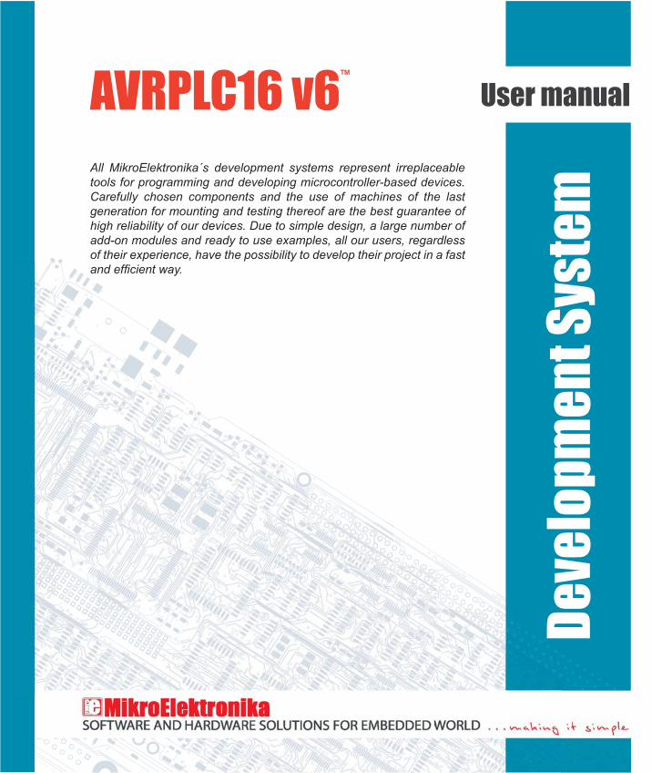
AVRPLC16 v6 ™ User manual All MikroElektronika´s development systems represent irreplaceable tools for programming and developing microcontroller-based devices. Carefully chosen components and the use of machines of the last generation for mounting and testing thereof are the best guarantee of high reliability of our devices. Due to simple design, a large number of add-on modules and ready to use examples, all our users, regardless of their experience, have the possibility to develop their project in a fast Development System
Transcript of tools for programming and developing microcontroller-based ...
AVRPLC16 v6™
User manual
All MikroElektronika´s development systems represent irreplaceable tools for programming and developing microcontroller-based devices. Carefully chosen components and the use of machines of the last generation for mounting and testing thereof are the best guarantee of high reliability of our devices. Due to simple design, a large number of add-on modules and ready to use examples, all our users, regardless of their experience, have the possibility to develop their project in a fast
Deve
lopm
ent S
yste
m

TO OUR VALUED CUSTOMERS
Mikroelektronika.The primary aim of our company is to design and produce high quality electronic products and to constantly improve the performance thereof in order to better suit your needs.
The Atmel name and logo, the Atmel logo, AVR, AVR (Logo), AVR Freaks, AVR Freaks (Logo), AVR Studio, IDIC, megaAVR, megaAVR (Logo), picoPower ® and tinyAVR ® are registered trademarks of Atmel Coorporation.
Nebojsa MaticGeneral Manager
3AVRPLC16 v6
MikroElektronika
page
TABLE OF CONTENTS
General information .......................................................................................................................... 4Key features ..................................................................................................................................... 51.0. Connecting the development system to a power supply source ............................................... 62.0. ATMEGA32 microcontroller ....................................................................................................... 73.0. Programming microcontroller .................................................................................................... 84.0. MMC/SD connector ................................................................................................................... 115.0. RS-485 module ......................................................................................................................... 126.0. RS-232 module ......................................................................................................................... 137.0. ADC module .............................................................................................................................. 148.0. Ethernet module ........................................................................................................................ 159.0. GSM module ............................................................................................................................. 1610.0. RTC module ............................................................................................................................1911.0. A/D inputs ............................................................................................................................... 2012.0. Relays and optocouplers ........................................................................................................ 2113.0. I/O ports .................................................................................................................................. 22
4 AVRPLC16 v6
MikroElektronika
page
General information
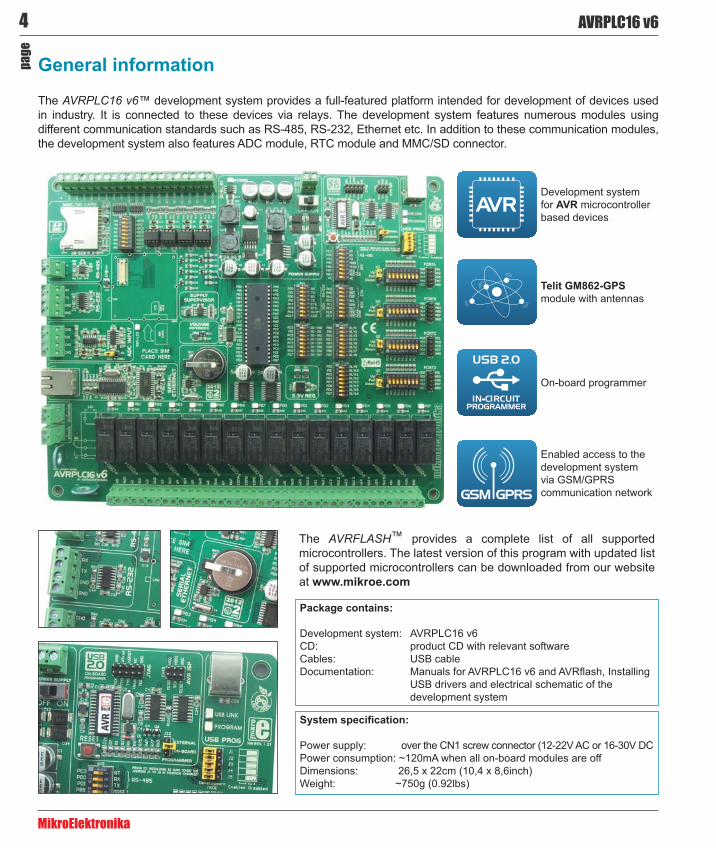
The AVRPLC16 v6™ development system provides a full-featured platform intended for development of devices used in industry. It is connected to these devices via relays. The development system features numerous modules using different communication standards such as RS-485, RS-232, Ethernet etc. In addition to these communication modules, the development system also features ADC module, RTC module and MMC/SD connector.
Power supply: over the CN1 screw connector (12-22V AC or 16-30V DCPower consumption: ~120mA when all on-board modules are offDimensions: 26,5 x 22cm (10,4 x 8,6inch)Weight: ~750g (0.92lbs)
Development system: AVRPLC16 v6CD: product CD with relevant softwareCables: USB cable
USB drivers and electrical schematic of the development system
The AVRFLASH™ provides a complete list of all supported microcontrollers. The latest version of this program with updated list of supported microcontrollers can be downloaded from our website at www.mikroe.com
Development system for AVR microcontroller based devices
Telit GM862-GPSmodule with antennas
On-board programmer
Enabled access to the development system via GSM/GPRS communication network
5AVRPLC16 v6
MikroElektronika
page
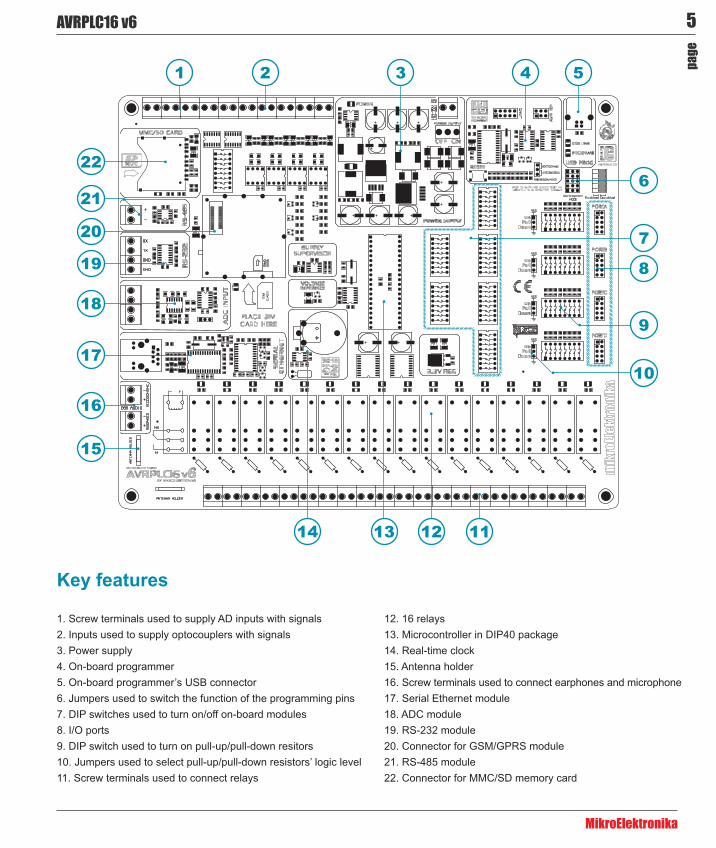
Key features
1. Screw terminals used to supply AD inputs with signals2. Inputs used to supply optocouplers with signals3. Power supply4. On-board programmer5. On-board programmer’s USB connector 6. Jumpers used to switch the function of the programming pins7. DIP switches used to turn on/off on-board modules8. I/O ports9. DIP switch used to turn on pull-up/pull-down resitors10. Jumpers used to select pull-up/pull-down resistors’ logic level11. Screw terminals used to connect relays
12. 16 relays13. Microcontroller in DIP40 package14. Real-time clock15. Antenna holder16. Screw terminals used to connect earphones and microphone17. Serial Ethernet module18. ADC module19. RS-232 module20. Connector for GSM/GPRS module21. RS-485 module22. Connector for MMC/SD memory card
11
1 2 3
6
8
7
16
17
18
19
20
22
15
4 5
9
10
121314
21
6 AVRPLC16 v6
MikroElektronika
page
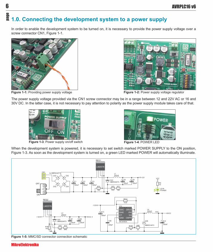
1.0. Connecting the development system to a power supplyIn order to enable the development system to be turned on, it is necessary to provide the power supply voltage over a screw connector CN1, Figure 1-1.
The power supply voltage provided via the CN1 screw connector may be in a range between 12 and 22V AC or 16 and 30V DC. In the latter case, it is not necessary to pay attention to polarity as the power supply module takes care of that.
When the development system is powered, it is necessary to set switch marked POWER SUPPLY to the ON position, Figure 1-3. As soon as the development system is turned on, a green LED marked POWER will automatically illuminate.
Providing power supply voltage Power supply voltage regulator
Figure 1-3: Power supply on/off switch Figure 1-4: POWER LED
MMC/SD connector connection schematic
7AVRPLC16 v6
MikroElektronika
page
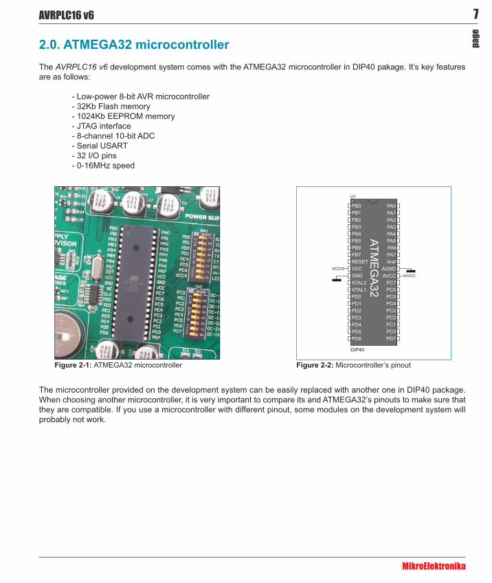
2.0. ATMEGA32 microcontrollerThe AVRPLC16 v6 development system comes with the ATMEGA32 microcontroller in DIP40 pakage. It’s key features are as follows:
- Low-power 8-bit AVR microcontroller- 32Kb Flash memory- 1024Kb EEPROM memory- JTAG interface- 8-channel 10-bit ADC- Serial USART- 32 I/O pins- 0-16MHz speed
ATMEGA32 microcontroller Microcontroller’s pinout
The microcontroller provided on the development system can be easily replaced with another one in DIP40 package. When choosing another microcontroller, it is very important to compare its and ATMEGA32’s pinouts to make sure that they are compatible. If you use a microcontroller with different pinout, some modules on the development system will probably not work.
8 AVRPLC16 v6
MikroElektronika
page
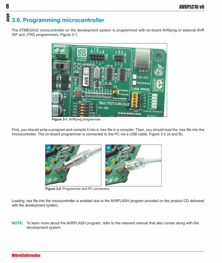
3.0. Programming microcontroller The ATMEGA32 microcontroller on the development system is programmed with on-board AVRprog or external AVR ISP and JTAG programmers, Figure 3-1.
Figure 3-1: AVRprog programmer
microcontroller. The on-board programmer is connected to the PC via a USB cable, Figure 3-2 (A and B).
with the development system.
To learn more about the AVRFLASH program, refer to the relevant manual that also comes along with the development system.
A B
Figure 3-2: Programmer and PC connection
9AVRPLC16 v6
MikroElektronika
page
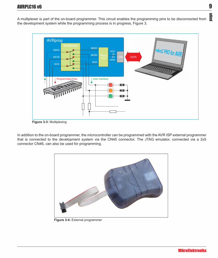
A multiplexer is part of the on-board programmer. This circuit enables the programming pins to be disconnected from the development system while the programming process is in progress, Figure 3.
Multiplexing
In addition to the on-board programmer, the microcontroller can be programmed with the AVR ISP external programmer that is connected to the development system via the CN45 connector. The JTAG emulator, connected via a 2x5 connector CN46, can also be used for programming.
External programmer

10 AVRPLC16 v6
MikroElektronika
page
Depending on the programmer that is used to program the microcontroller, it is necessary to place jumper J10 in the appropriate position, Figure 3-5.
The on-board programmer is in use when jumper J10 is placed in the ON-BOARD position A
The external programmer is in use when jumper J10 is placed in the EXTERNAL positionB
If necessary, the microcontroller’s programming pins may be disconnected from the programmer. Placing jumpers J1-J5 in the Disabled position causes the programming pins to be disconnected from the programmer, and at the same time connected to the rest of the development system. In this case they can be used as I/O pins.
A B
J1-J5 in Enabled position, the microcontroller’s programming pins are connected to the programmerA
J1-J5 in Disabled position, the microcontroller’s programming pins are not connected to the programmerB
A B
The position of jumper J10
The position of jumpers J1-J5
11AVRPLC16 v6
MikroElektronika
page
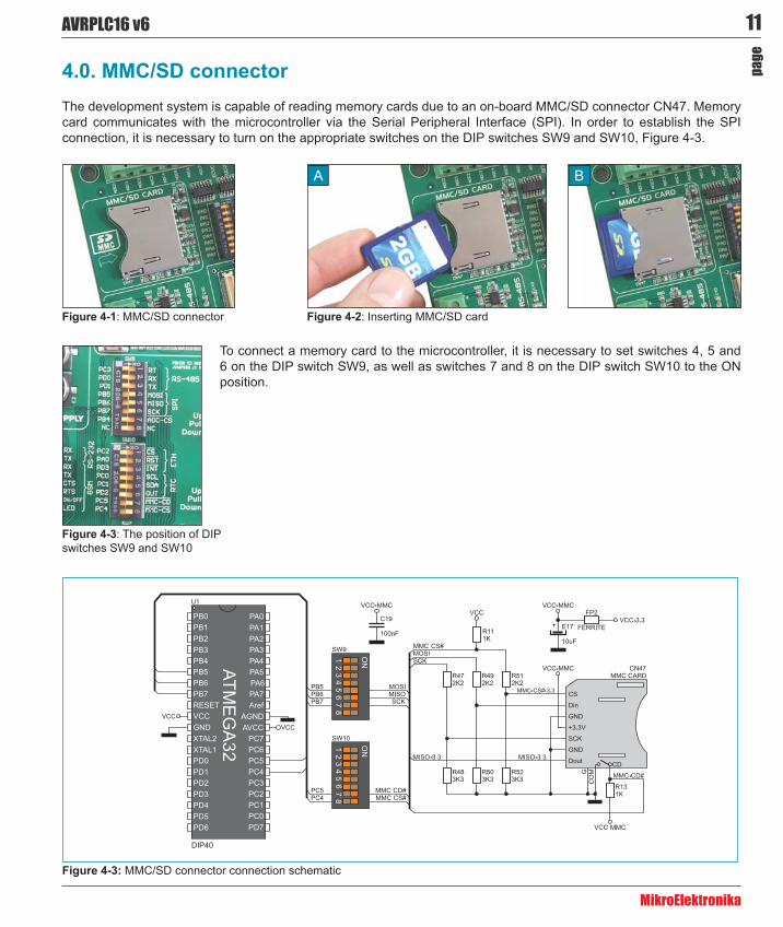
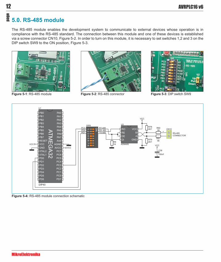
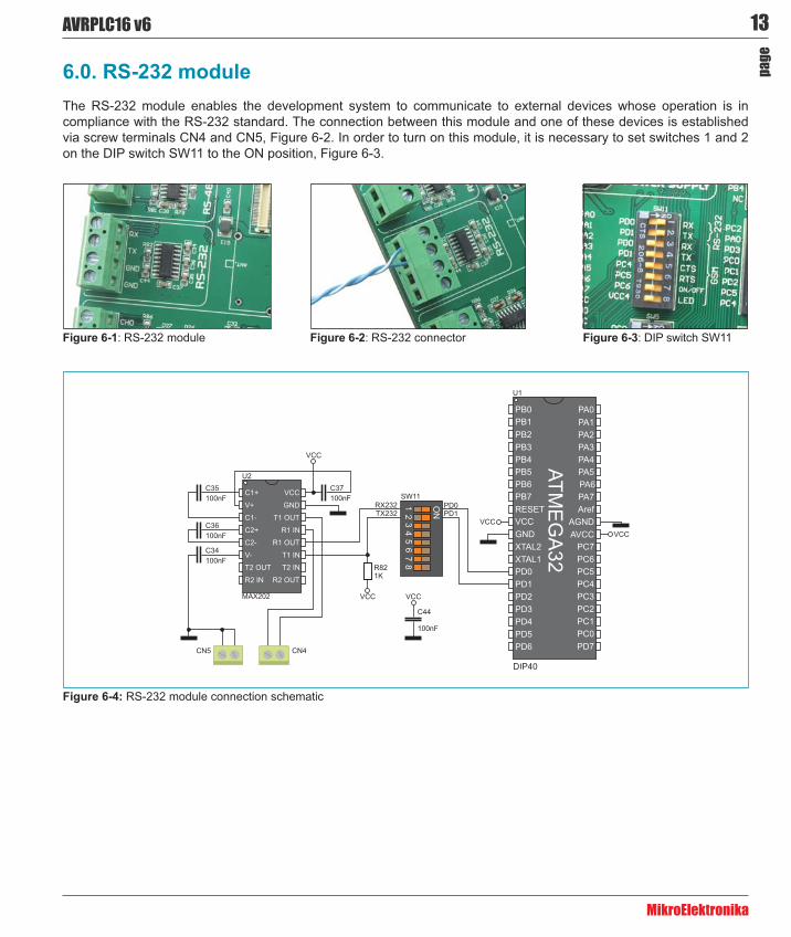
To connect a memory card to the microcontroller, it is necessary to set switches 4, 5 and 6 on the DIP switch SW9, as well as switches 7 and 8 on the DIP switch SW10 to the ON position.
4.0. MMC/SD connector The development system is capable of reading memory cards due to an on-board MMC/SD connector CN47. Memory card communicates with the microcontroller via the Serial Peripheral Interface (SPI). In order to establish the SPI connection, it is necessary to turn on the appropriate switches on the DIP switches SW9 and SW10, Figure 4-3.
Figure 4-1: MMC/SD connector
Figure 4-3: The position of DIP switches SW9 and SW10
MMC/SD connector connection schematic
Figure 4-2: Inserting MMC/SD card
A B
12 AVRPLC16 v6
MikroElektronika
page
5.0. RS-485 module The RS-485 module enables the development system to communicate to external devices whose operation is in compliance with the RS-485 standard. The connection between this module and one of these devices is established via a screw connector CN10, Figure 5-2. In order to turn on this module, it is necessary to set switches 1,2 and 3 on the DIP switch SW9 to the ON position, Figure 5-3.
RS-485 module connection schematic
Figure 5-1: RS-485 module Figure 5-2: RS-485 connector Figure 5-3: DIP switch SW9
13AVRPLC16 v6
MikroElektronika
page
6.0. RS-232 moduleThe RS-232 module enables the development system to communicate to external devices whose operation is in compliance with the RS-232 standard. The connection between this module and one of these devices is established via screw terminals CN4 and CN5, Figure 6-2. In order to turn on this module, it is necessary to set switches 1 and 2 on the DIP switch SW11 to the ON position, Figure 6-3.
RS-232 module connection schematic
Figure 6-1: RS-232 module Figure 6-2: RS-232 connector Figure 6-3: DIP switch SW11
14 AVRPLC16 v6
MikroElektronika
page
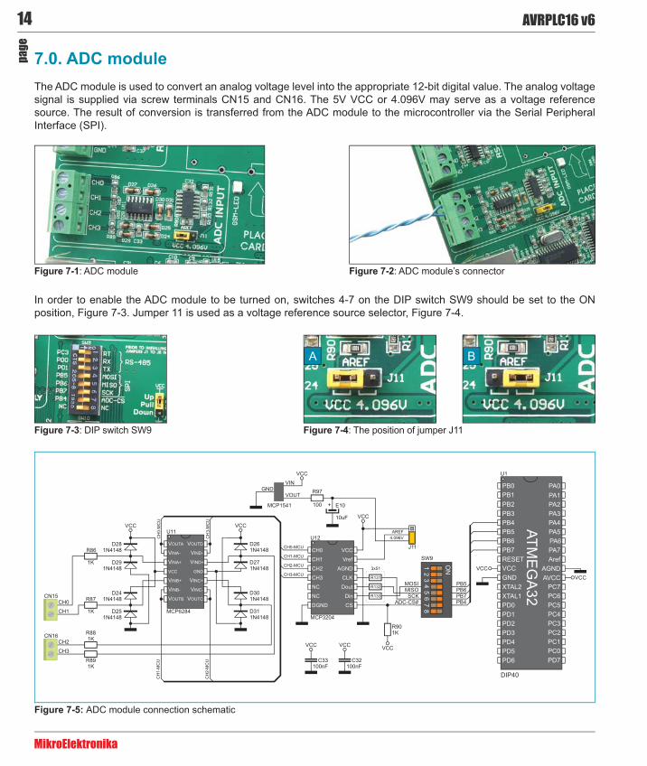
7.0. ADC module The ADC module is used to convert an analog voltage level into the appropriate 12-bit digital value. The analog voltage signal is supplied via screw terminals CN15 and CN16. The 5V VCC or 4.096V may serve as a voltage reference source. The result of conversion is transferred from the ADC module to the microcontroller via the Serial Peripheral Interface (SPI).
Figure 7-1: ADC module Figure 7-2: ADC module’s connector
ADC module connection schematic
Figure 7-3: DIP switch SW9 Figure 7-4: The position of jumper J11
In order to enable the ADC module to be turned on, switches 4-7 on the DIP switch SW9 should be set to the ON position, Figure 7-3. Jumper 11 is used as a voltage reference source selector, Figure 7-4.
A B
15AVRPLC16 v6
MikroElektronika
page
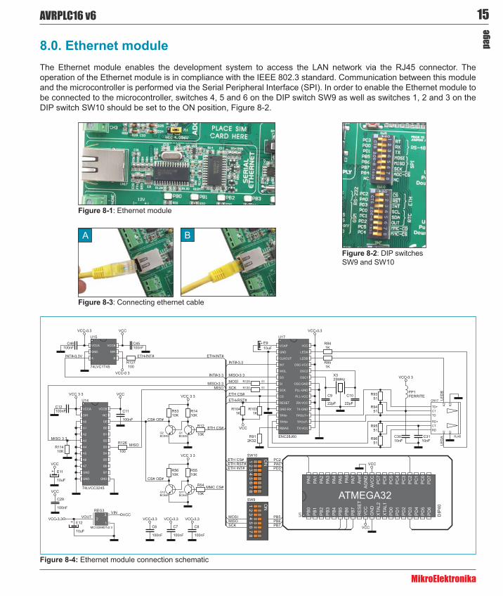
8.0. Ethernet module The Ethernet module enables the development system to access the LAN network via the RJ45 connector. The operation of the Ethernet module is in compliance with the IEEE 802.3 standard. Communication between this module and the microcontroller is performed via the Serial Peripheral Interface (SPI). In order to enable the Ethernet module to be connected to the microcontroller, switches 4, 5 and 6 on the DIP switch SW9 as well as switches 1, 2 and 3 on the DIP switch SW10 should be set to the ON position, Figure 8-2.
Ethernet module connection schematic
Figure 8-1: Ethernet module
Figure 8-3: Connecting ethernet cable
Figure 8-2: DIP switches SW9 and SW10
A B
16 AVRPLC16 v6
MikroElektronika
page
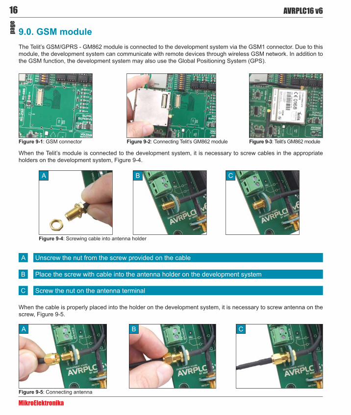
9.0. GSM module The Telit’s GSM/GPRS - GM862 module is connected to the development system via the GSM1 connector. Due to this module, the development system can communicate with remote devices through wireless GSM network. In addition to the GSM function, the development system may also use the Global Positioning System (GPS).
Figure 9-1: GSM connector
Figure 9-4: Screwing cable into antenna holder
Figure 9-5: Connecting antenna
A
A
Figure 9-2: Connecting Telit’s GM862 module Figure 9-3: Telit’s GM862 module
When the Telit’s module is connected to the development system, it is necessary to screw cables in the appropriate holders on the development system, Figure 9-4.
B
B
C
C
Unscrew the nut from the screw provided on the cableA
Place the screw with cable into the antenna holder on the development systemB
Screw the nut on the antenna terminalC
When the cable is properly placed into the holder on the development system, it is necessary to screw antenna on the screw, Figure 9-5.
17AVRPLC16 v6
MikroElektronika
page
Figure 9-8: Connectors used to connect microphone and speaker
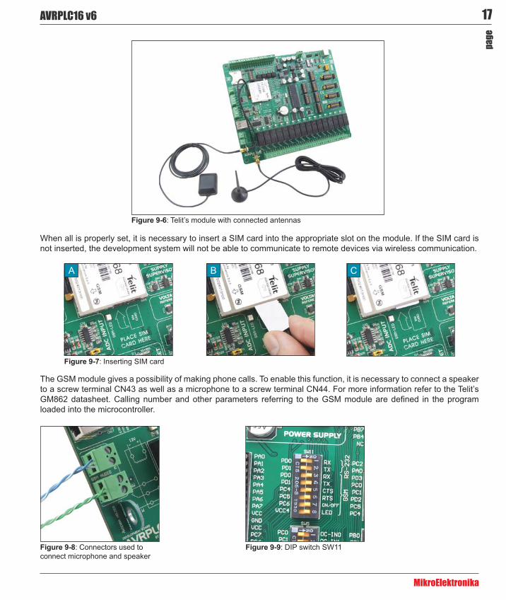
Figure 9-6: Telit’s module with connected antennas
Figure 9-7: Inserting SIM card
A B C
When all is properly set, it is necessary to insert a SIM card into the appropriate slot on the module. If the SIM card is not inserted, the development system will not be able to communicate to remote devices via wireless communication.
The GSM module gives a possibility of making phone calls. To enable this function, it is necessary to connect a speaker to a screw terminal CN43 as well as a microphone to a screw terminal CN44. For more information refer to the Telit’s
loaded into the microcontroller.
Figure 9-9: DIP switch SW11
18 AVRPLC16 v6
MikroElektronika
page
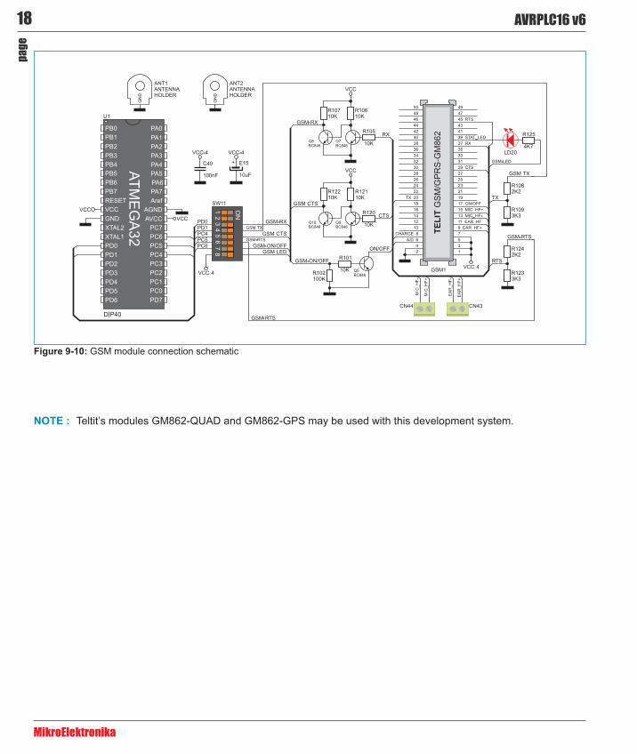
GSM module connection schematic
Teltit’s modules GM862-QUAD and GM862-GPS may be used with this development system.
19AVRPLC16 v6
MikroElektronika
page
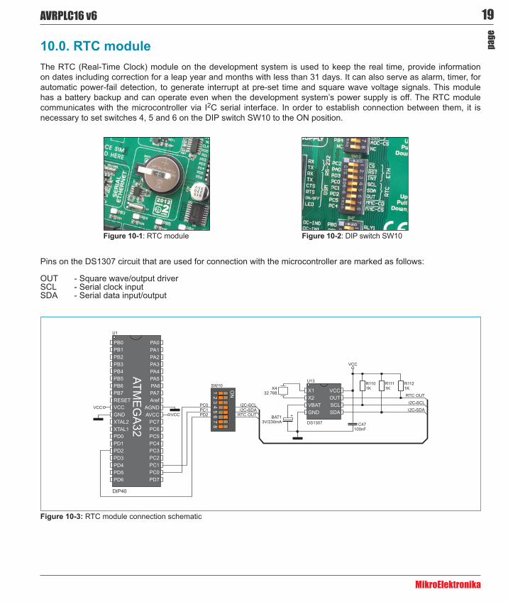
10.0. RTC moduleThe RTC (Real-Time Clock) module on the development system is used to keep the real time, provide information on dates including correction for a leap year and months with less than 31 days. It can also serve as alarm, timer, for automatic power-fail detection, to generate interrupt at pre-set time and square wave voltage signals. This module has a battery backup and can operate even when the development system’s power supply is off. The RTC module communicates with the microcontroller via I2C serial interface. In order to establish connection between them, it is necessary to set switches 4, 5 and 6 on the DIP switch SW10 to the ON position.
Figure 10-1: RTC module Figure 10-2: DIP switch SW10
RTC module connection schematic
Pins on the DS1307 circuit that are used for connection with the microcontroller are marked as follows:
OUT - Square wave/output driverSCL - Serial clock inputSDA - Serial data input/output
20 AVRPLC16 v6
MikroElektronika
page
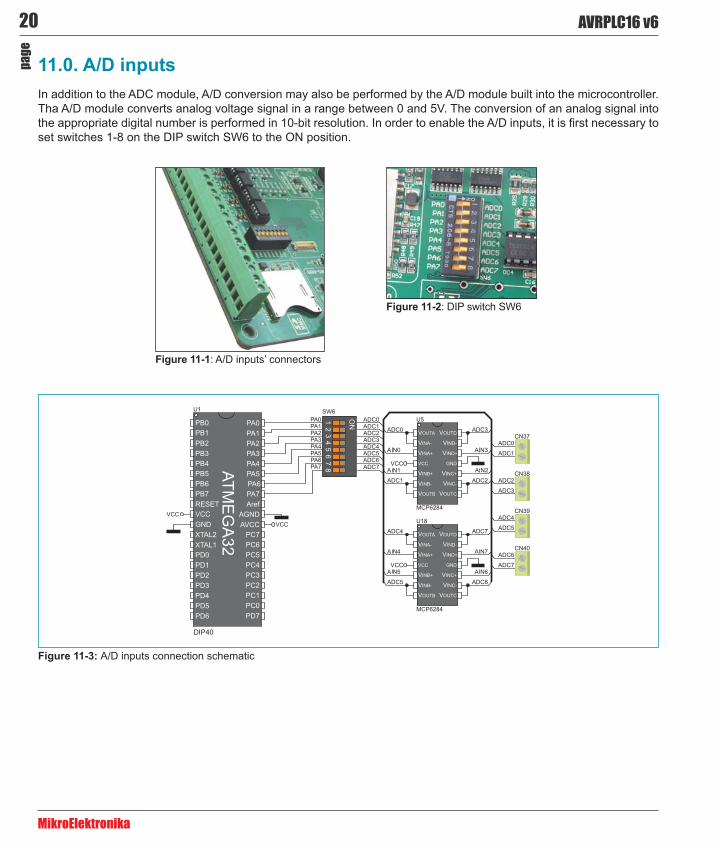
11.0. A/D inputsIn addition to the ADC module, A/D conversion may also be performed by the A/D module built into the microcontroller. Tha A/D module converts analog voltage signal in a range between 0 and 5V. The conversion of an analog signal into
set switches 1-8 on the DIP switch SW6 to the ON position.
Figure 11-1: A/D inputs’ connectors
Figure 11-2: DIP switch SW6
A/D inputs connection schematic
21AVRPLC16 v6
MikroElektronika
page
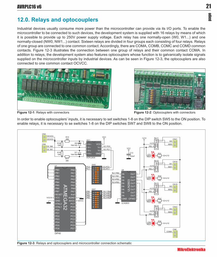
12.0. Relays and optocouplersIndustrial devices usually consume more power than the microcontroller can provide via its I/O ports. To enable the microcontroller to be connected to such devices, the development system is supplied with 16 relays by means of which it is possible to provide up to 250V power supply voltage. Each relay has one normally-open (W0, W1...) and one normally-closed (NW0, NW1...) contact. Sixteen relays are divided in four groups each consisting of four relays. Relays of one group are connected to one common contact. Accordingly, there are COMA, COMB, COMC and COMD common contacts. Figure 12-3 illustrates the connection between one group of relays and their common contact COMA. In addition to relays, the development system also features optocouplers whose function is to galvanically isolate signals supplied on the microcontroller inputs by industrial devices. As can be seen in Figure 12-3, the optocouplers are also connected to one common contact OCVCC.
Figure 12-3: Relays and optocouplers and microcontroller connection schematic
Figure 12-1: Relays with connectors
In order to enable optocouplers’ inputs, it is necessary to set switches 1-8 on the DIP switch SW5 to the ON position. To enable relays, it is necessary to se switches 1-8 on the DIP switches SW7 and SW8 to the ON position.
Figure 12-2: Optocouplers with connectors
22 AVRPLC16 v6
MikroElektronika
page
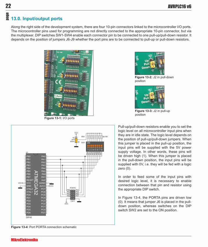
13.0. Input/output portsAlong the right side of the development system, there are four 10-pin connectors linked to the microcontroller I/O ports. The microcontroller pins used for programming are not directly connected to the appropriate 10-pin connector, but via the multiplexer. DIP switches SW1-SW4 enable each connector pin to be connected to one pull-up/pull-down resistor. It depends on the position of jumpers J6-J9 whether the port pins are to be connected to pull-up or pull-down resistors.
Figure 13-4: Port PORTA connection schematic
J2 in pull-down position
J2 in pull-up position
I/O ports
Pull-up/pull-down resistors enable you to set the logic level on all microcontroller input pins when they are in idle state. The logic level depends on the position of pull-up/pull-down jumpers. When this jumper is placed in the pull-up position, the input pins will be supplied with the 5V power supply voltage. In other words, these pins will be driven high (1). When this jumper is placed in the pull-down position, the input pins will be supplied with 0V, i.e. they will be fed with a logic zero (0).
In order to feed some of the input pins with desired logic level, it is necessary to enable connection between that pin and resistor using the appropriate DIP switch.
In Figure 13-4, the PORTA pins are driven low (0). It means that jumper J6 is placed in the pull-down position, whereas switches on the DIP switch SW2 are set to the ON position.

DISCLAIMER
All the products owned by MikroElektronika are protected by copyright law and international copyright treaty. Therefore, this manual is to be treated as any other copyright material. No part of this manual, including product and software described herein, may be reproduced, stored in a retrieval system, translated or transmitted in any form or by any means, without the prior written permission of MikroElektronika. The
manual is prohibited.
MikroElektronika provides this manual ‘as is’ without warranty of any kind, either expressed or implied,
purpose.
MikroElektronika shall assume no responsibility or liability for any errors, omissions and inaccuracies that may
of this manual or product, even if MikroElektronika has been advised of the possibility of such damages. MikroElektronika reserves the right to change information contained in this manual at any time without prior notice, if necessary.
HIGH RISK ACTIVITIES
The products of MikroElektronika are not fault – tolerant nor designed, manufactured or intended for use or resale as on – line control equipment in hazardous environments requiring fail – safe performance, such as
life support machines or weapons systems in which the failure of Software could lead directly to death, personal injury or severe physical or environmental damage (‘High Risk Activities’). MikroElektronika and its
TRADEMARKS
The Mikroelektronika name and logo, the Mikroelektronika logo, mikroC, mikroC PRO, mikroBasic, mikro--
of Mikroelektronika. All other trademarks mentioned herein are property of their respective companies.
All other product and corporate names appearing in this manual may or may not be registered trademarks
©MikroelektronikaTM
If yo
u w
ant t
o le
arn
mor
e ab
out o
ur p
rodu
cts,
ple
ase
visi
t our
web
site
at w
ww
.mik
roe.
com
If yo
u ar
e ex
perie
ncin
g so
me
prob
lem
s w
ith a
ny o
f our
pro
duct
s or
just
nee
d ad
ditio
nal i
nfor
mat
ion,
ple
ase
plac
e yo
ur ti
cket
at
ww
w.m
ikro
e.co
m/e
n/su
ppor
t