
Tong Van Luyen - VNU · be specified, and the minimum possible first-null beamwidth is obtained....
27
VIETNAM NATIONAL UNIVESITY, HANOI UNIVERSITY OF ENGINEERING AND TECHNOLOGY Tong Van Luyen RESEARCH AND DEVELOPMENT OF ADAPTIVE BEAMFORMERS FOR INTERFERENCE SUPPRESSION IN SMART ANTENNAS Major: Communication Engineering Major code: 62 52 02 08 Brief of the Dissertation for the Degree of Doctor of Philosophy in Electronics and Communications Engineering Hanoi - 2017
Transcript of Tong Van Luyen - VNU · be specified, and the minimum possible first-null beamwidth is obtained....

VIETNAM NATIONAL UNIVESITY, HANOI
UNIVERSITY OF ENGINEERING AND TECHNOLOGY
Tong Van Luyen
RESEARCH AND DEVELOPMENT OF ADAPTIVE
BEAMFORMERS FOR INTERFERENCE SUPPRESSION
IN SMART ANTENNAS
Major: Communication Engineering
Major code: 62 52 02 08
Brief of the Dissertation
for the Degree of Doctor of Philosophy
in Electronics and Communications Engineering
Hanoi - 2017

This study has been conducted and completed at the University of Engineering and Technology, Vietnam National University, Hanoi.
Supervisor: Assoc. Prof. Dr.-Ing. Truong Vu Bang Giang
Reviewer: ……………………………………………………
…………………………………………………....
Reviewer: ……………………………………………………
…………………………………………………....
Reviewer: ……………………………………………………
…………………………………………………....
The dissertation will be defended at university level, in the presence of the Doctoral Examination Board of National University, Hanoi.
Location: VNU University of Engineering and Technology
Time:
The dissertation can be found at:
- National Library of Vietnam
- Library and Information Center, Vietnam National
University, Hanoi.

1
Introduction
I. Rationale for the Study
Beamforming (BF) for smart antennas exhibits various benefits in coverage, data rate, spectrum efficiency, interference suppression, which are all the vital factors of wireless communication systems.
Nowadays, the increasing number of wireless devices causes serious pollution in the electromagnetic propagation environment. In this context, smart antennas with pattern nulling capabilities emerge as a promising solution for interference suppression applications. However, pattern nulling has resulted in an increase in complexity of the computation and requiring the effective optimization tools.
Optimization techniques have been widely applied in BF for antenna array pattern synthesis including pattern nulling. To overcome the limitations of the classical optimization techniques, various nature-inspired optimization algorithms have been developed such as genetic algorithm (GA) and particle swarm optimization (PSO). These algorithms have been proposed and implemented with their own benefits and limitations in pattern nulling. In general, there are still some challenges for the pattern nulling based on these nature-inspired algorithms as: (i) computation speed and performance; (ii) the lack of detailed analysis about the general process to obtain pattern nulling, which leads to the difficulty in understanding, applying and developing applications.
Recently, Bat algorithm (BA) is a new nature-inspired computation technique based on the bat behavior. This algorithm was applied for the first time for BF in 2016, and since then has been regarded as a promising optimization tool for adaptive BF in terms of computation time.
Therefore, the development of adaptive beamformers for interference suppression is obviously still a challenge for researchers in the context of improving computational speed and capability of pattern nulling. These challenges are the motivation for further researches in this dissertation.

2
II. Objectives, Subjects, and Scope of the Study
II.1. Objectives - To research and propose a general process to build BA-based
adaptive beamformers to suppress interferences for ULAs in smart antennas.
- To implement the general process to develop three types of BA-based adaptive beamformers to suppress interferences for ULAs using amplitude-only, phase-only, and complex-weight control techniques.
II.2. Subjects and Scope This study focuses on pattern synthesis of antenna arrays,
adaptive BF techniques for antenna arrays, nature-inspired optimization algorithms, and interference suppression using beamformers.
III. Significance of the Study
- Proposal of a general process to build BA-based adaptive beamformers for interference suppression applications in smart antennas;
- Development of three BA-based adaptive beamformers for interference suppression in radar and wireless communication networks, which use amplitude-only, phase-only, and complex-weight control techniques, respectively. These beamformers have been implemented for 20-element ULAs. The beamformers have shown the ability to place precisely a single, multiple, and broad nulls at directions of interferences, to suppress sidelobes, and to maintain the main lobe.
IV. Dissertation Outline
The dissertation consists of an introduction, three chapters, and a conclusion. Chapter 1 presents an overview of beamforming. In Chapter 2, a general process will be proposed to build BA-based adaptive beamformers for pattern nulling of ULAs. Three different BA-based adaptive beamformers will be developed for pattern nulling of ULAs in Chapter 3.
3
Chapter 1
Overview of Beamforming
This chapter presents an overview of BF, technical basis of BF including application models, mathematical basis, optimization techniques that are related to the contents of this dissertation.
1.1. Beamforming for Smart Antennas
In smart antennas, BF is used along with antenna array to form an equivalent directional antenna system. This directional antenna system is able to focus the radiation power or spatially receive power in a particular direction in space. This spatial radiation or power reception of smart antennas, also called “beam”, is achieved by electrical control using BF, in which the desired signals in particular directions are boosted and the interferences in the others are minimized.
In BF, the signal corresponding to each element has been controlled by a specific principle. This control aims to form and steer the beam of the array in such a way as: (i) form and steer the main beam to a desired direction; (ii) suppress the sidelobes; (iii) and set nulls at undesired directions. In general, common controlling parameters are the amplitude, the phase, or both the amplitude and the phase of excitations corresponding to the elements. These controlled parameters are also called “weights”.
A simple structure of digital beamformers in the receiving end is displayed in Figure 1.4. Digital beamformers carry out weighting the receiving signals, thereby adjusting their amplitudes and phases such a way that when added together they form desired output. Digital beamformers can adjust the value of weights (��) to point the beam in any wanted direction and to manipulate its shape to optimize the system performance. Therefore, the flexibility of digital beamformer allows the full implementation of adaptive beamforming, which is able to automatically adapt its response to the different conditions and has various applications in reality.

4
Figure 1.4. Block diagram of digital beamformers at the receiving end.
1.2. Mathematic Basis of Smart Antennas
1.2.1. Geometric Relations This section presents the geometric relations and signals in linear
arrays.
1.2.2. The Model of Smart Antennas with Linear Array This section presents a basic model of linear-array smart
antennas.
If each element is identical with the element radiation pattern, f0(θ,φ), the radiation pattern of the array, f(θ,φ), has been calculated by the pattern multiplication principle as ���, �� = ���, ������, �� (1.11)
The array factor (AF) can be expressed by ����, �� = � ���, �� (1.12)
where: � = ���� …����� (1.13)
is the weighting vector, in which T denotes transposition, and ���, �� = �1����������� …���������������� � (1.14)
is the steering vector.
Additionally, the output at time n, y(n), is given by a linear combination of the data at M elements at time n as
5
!��"� = �#$�"� (1.16)
where: the superscript H represents Hermitian transpose; and $�"� = �%�"�%��"�…%����"�� is the receiving signal vector.
1.3. Optimal Beamforming Techniques
1.3.1. Classical Optimization Techniques Minimum Mean Square Error is one of the most widely used
performance measures to develop conventional adaptive beamforming algorithms such as Sample Matrix Inversion, Least Mean Square, and Recursive Least Square. Dolph-Chebyshev weighting is a popular method because the sidelobe level (SLL) can be specified, and the minimum possible first-null beamwidth is obtained.
1.3.2. Nature-inspired Optimization 1.3.2.1. Nature-inspired Optimization Approach
A combination of nature-inspired optimiza-tion algorithms (global optimization algorithms), computational electromag-netics, and computer-processing is a promising tool for solving challenges of smart antennas in wireless communications.
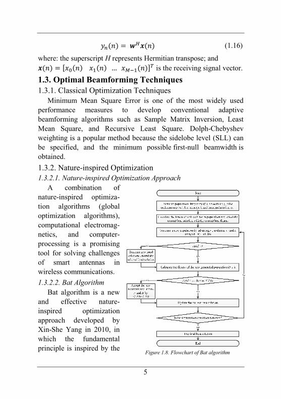
1.3.2.2. Bat Algorithm Bat algorithm is a new
and effective nature-inspired optimization approach developed by Xin-She Yang in 2010, in which the fundamental principle is inspired by the
Figure 1.8. Flowchart of Bat algorithm

6
social behavior of bats and the phenomenon of echolocation to sense distance. The flowchart of Bat algorithm has been presented in Figure 1.8. In BA, each bat (i) is defined by its position %�&, velocity '�&, frequency ��, loudness ��&, and the emission pulse rate (�& in a d-dimensional search space. The new solutions %�& and velocities '�& at time step ) are given by �� =���� + ���+, − �����. (1.18)'�& ='�&�� + /%�& −%∗1�� (1.19)%�& = %�&�� + '�& (1.20)
where . ∈ �0,1� is a random vector drawn from a uniform distribution. Here %∗ is the current global best location (solution). For the local search part, a new solution for each bat is generated locally using random walk as %�45 =%67� + 8�& (1.21)where 8 ∈ �0,1� is a random number, while �& is the average loudness of all the bats at time step t. Furthermore, in consecutive iterations, the loudness �� and the rate (� of emission pulse can be updated by ��&9� = :��& (1.22) (�&9� = (��1 − exp�−>)�� (1.23)
where 0 < α < 1 and 0 < γ are constants.
1.4. Chapter Conclusions
In this chapter, the fundamentals of BF has been presented including basic model of BF for smart antenna, and mathematical basis of BF for ULAs in the array pattern synthesis. Additionally, the optimization techniques for BF have been introduced and focused on the advantages and potential of nature-inspired optimization, specifically Bat algorithm. These contents will be applied as the fundamental for proposals presented in the next chapters.
7
Chapter 2
General Process to Develop BA-based Adaptive
Beamformers for Interference Suppression
In this chapter, a general process will be proposed to build BA-based adaptive beamformers for pattern nulling of ULAs. This proposal has been presented in papers [1-3].
2.1. Problem Determination
The BA-based adaptive beamformers for interference suppression application will be developed in following manners:
- Based on the principle presented in chapter 1, in which beamformers are equipped with Direction-Of-Arrival estimators;
- Applied for pattern nulling of ULAs including a single null, multiple nulls, and a broad null at directions of interferences;
- Able to maintain the direction of the main lobe and the beamwidth while suppressing the sidelobes.
2.2. Array Factor Building
Figure 2.1 presents the investigated ULAs with the array factor:
����� = ? ��@�A�@ ����B������ = ? C������B������9DE�@
�A�@ (2.1)
where: �� =��F4 + G���� = C���DE is the complex excitation
(weight) of nth element; H = �IJ is the wavenumber; λ is wave length;
and d is the distance between adjacent elements.
Figure 2.4. General process to build adaptive beamformers.
8
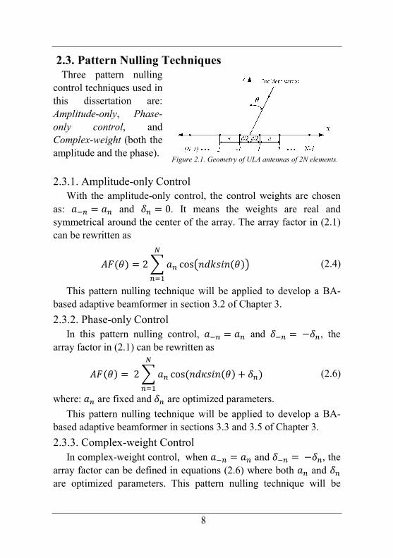
2.3. Pattern Nulling Techniques
Three pattern nulling control techniques used in this dissertation are: Amplitude-only, Phase-only control, and Complex-weight (both the amplitude and the phase).
2.3.1. Amplitude-only Control With the amplitude-only control, the control weights are chosen
as: C�� = C� and K� = 0. It means the weights are real and symmetrical around the center of the array. The array factor in (2.1) can be rewritten as
����� = 2?C�@�A� cos/"PHQR"���1 (2.4)
This pattern nulling technique will be applied to develop a BA-based adaptive beamformer in section 3.2 of Chapter 3.
2.3.2. Phase-only Control In this pattern nulling control, C�� = C� and K�� =−K�, the
array factor in (2.1) can be rewritten as
����� = 2?C�@�A� cos�"PSQR"��� + K�� (2.6)
where: C� are fixed and K� are optimized parameters.
This pattern nulling technique will be applied to develop a BA-based adaptive beamformer in sections 3.3 and 3.5 of Chapter 3.
2.3.3. Complex-weight Control In complex-weight control, when C�� = C� and K�� =−K�, the
array factor can be defined in equations (2.6) where both C� and K� are optimized parameters. This pattern nulling technique will be
Figure 2.1. Geometry of ULA antennas of 2N elements.

9
applied to develop a BA-based adaptive beamformer in section 3.4 of Chapter 3.
2.4. Formation of Objective Function
A new objective function, F, has been developed for pattern nulling as
� = TU�����,for� = ����,elsewhere (2.9)
where: N(θ) has been chosen as 10000 by simulation processes; F1 is used for placing the null points and is defined as
�� =?|��6����|�\�A� (2.10)
where I is the maximum number of interferences; F2 is used to reduce sidelobes level (SLL) and to keep the beamwidth within a maximum allowable change.
�� = ? |��6��� − ������|�,]^�A�]^ �R)ℎ� ≠ �� (2.11)
2.5. Transformation of BA to Adaptive Beamforming
Algorithms
BA is being transformed to be an adaptive beamforming algorithm. Essential steps will be proceeded as follows:
- Mapping locations (%) of bats to a set of weights in BF, which are variables in the optimization process;
- Defining the dimensional search space (d) of a variable as equal as the number of weights (related to the number of array elements, e.g. 20 for a 20-eleement ULA);
- Specifying the values of parameters, e.g. normalized amplitudes of weights are limited in the range of [0, 1] and the phase of weights are in the range of [-π, π].
10
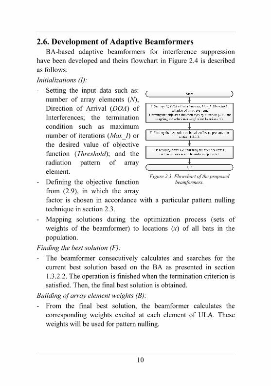
2.6. Development of Adaptive Beamformers
BA-based adaptive beamformers for interference suppression have been developed and theirs flowchart in Figure 2.4 is described as follows:
Initializations (I):
- Setting the input data such as: number of array elements (N), Direction of Arrival (DOA) of Interferences; the termination condition such as maximum number of iterations (Max_I) or the desired value of objective function (Threshold); and the radiation pattern of array element.
- Defining the objective function from (2.9), in which the array factor is chosen in accordance with a particular pattern nulling technique in section 2.3.
- Mapping solutions during the optimization process (sets of weights of the beamformer) to locations (x) of all bats in the population.
Finding the best solution (F):
- The beamformer consecutively calculates and searches for the current best solution based on the BA as presented in section 1.3.2.2. The operation is finished when the termination criterion is satisfied. Then, the final best solution is obtained.
Building of array element weights (B):
- From the final best solution, the beamformer calculates the corresponding weights excited at each element of ULA. These weights will be used for pattern nulling.
Figure 2.3. Flowchart of the proposed beamformers.
11
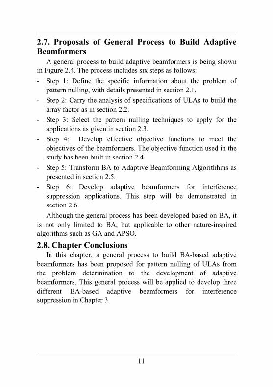
2.7. Proposals of General Process to Build Adaptive
Beamformers
A general process to build adaptive beamformers is being shown in Figure 2.4. The process includes six steps as follows:
- Step 1: Define the specific information about the problem of pattern nulling, with details presented in section 2.1.
- Step 2: Carry the analysis of specifications of ULAs to build the array factor as in section 2.2.
- Step 3: Select the pattern nulling techniques to apply for the applications as given in section 2.3.
- Step 4: Develop effective objective functions to meet the objectives of the beamformers. The objective function used in the study has been built in section 2.4.
- Step 5: Transform BA to Adaptive Beamforming Algorithhms as presented in section 2.5.
- Step 6: Develop adaptive beamformers for interference suppression applications. This step will be demonstrated in section 2.6.
Although the general process has been developed based on BA, it is not only limited to BA, but applicable to other nature-inspired algorithms such as GA and APSO.
2.8. Chapter Conclusions
In this chapter, a general process to build BA-based adaptive beamformers has been proposed for pattern nulling of ULAs from the problem determination to the development of adaptive beamformers. This general process will be applied to develop three different BA-based adaptive beamformers for interference suppression in Chapter 3.
12
Chapter 3
Developments of BA-based Adaptive Beamformers
for Interference Suppression
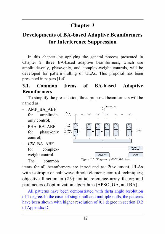
In this chapter, by applying the general process presented in Chapter 2, three BA-based adaptive beamformers, which use amplitude-only, phase-only, and complex-weight controls, will be developed for pattern nulling of ULAs. This proposal has been presented in papers [1-4]
3.1. Common Items of BA-based Adaptive
Beamformers
To simplify the presentation, three proposed beamformers will be named as
- AMP_BA_ABF for amplitude-only control;
- PHA_BA_ABF for phase-only control;
- CW_BA_ABF for complex-weight control.
The common items for all beamformers are introduced as: 20-element ULAs with isotropic or half-wave dipole element; control techniques; objective function in (2.9); initial reference array factor; and parameters of optimization algorithms (APSO, GA, and BA).
All patterns have been demonstrated with theta angle resolution of 1 degree. In the cases of single null and multiple nulls, the patterns have been shown with higher resolution of 0.1 degree in section D.2 of Appendix D.
Figure 3.1. Diagram of AMP_BA_ABF.

13
3.2. The Beamformer Using Amplitude-only Control
3.2.1. Diagram of the Beamformer According the process as presented in Chapter 2, the diagram of
BA-based adaptive beamformers using amplitude-only control is shown in Figure 3.1, in which the amplitude (a-n = an) are variable, the phase δn =0, and with 20-isotropic element ULAs.
3.2.2. Numerical Results and Discussions To demonstrate the capability and flexibility of our proposed
beamformer for interference suppression, five scenarios have been built. The initial parameters have been chosen for all investigation scenarios as: population size (pop) is 1000 and number of iterations (ite) is 20 (except for the first scenario). The simulation results are average values of Monte Carlo simulations with 1000 times for the first scenario, and 100 times for the others.
3.2.2.1. Convergence Characteristics In the first scenario,
convergence rates of the beamformers based on BA, GA, APSO have been investigated. In order to do that, these beamformers have been applied to obtain the desired optimization pattern as 20-isotropic element Chebyshev array pattern with SLL of -30 dB. Additionally, the initial population has been randomly generated, ite is 100. It can be seen from Figure 3.2 that BA-based beamformer converges much faster than APSO and GA ones.
3.2.2.2. Pattern with a Single Null In the second scenario, the optimized patterns with single null
have been demonstrated. This null is arbitrarily set at any angle, which is chosen at peak of the second side lobe (140) in this test case. The population has been initialized as weights of 20-element Chebyshev array with SLL of -30 dB. As shown in Error! Reference source not found., the optimized pattern by the BA-
Figure 3.2. Objective function comparisons
of BA, PSO, and GA.
14
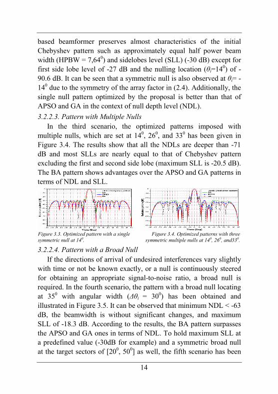
based beamformer preserves almost characteristics of the initial Chebyshev pattern such as approximately equal half power beam width (HPBW = 7,640) and sidelobes level (SLL) (-30 dB) except for first side lobe level of -27 dB and the nulling location (θi=140) of -90.6 dB. It can be seen that a symmetric null is also observed at θi= -140 due to the symmetry of the array factor in (2.4). Additionally, the single null pattern optimized by the proposal is better than that of APSO and GA in the context of null depth level (NDL).
3.2.2.3. Pattern with Multiple Nulls In the third scenario, the optimized patterns imposed with
multiple nulls, which are set at 140, 260, and 330 has been given in Figure 3.4. The results show that all the NDLs are deeper than -71 dB and most SLLs are nearly equal to that of Chebyshev pattern excluding the first and second side lobe (maximum SLL is -20.5 dB). The BA pattern shows advantages over the APSO and GA patterns in terms of NDL and SLL.
Figure 3.3. Optimized pattern with a single symmetric null at 140.
Figure 3.4. Optimized patterns with three symmetric multiple nulls at 140, 260, and330.
3.2.2.4. Pattern with a Broad Null If the directions of arrival of undesired interferences vary slightly
with time or not be known exactly, or a null is continuously steered for obtaining an appropriate signal-to-noise ratio, a broad null is required. In the fourth scenario, the pattern with a broad null locating at 350 with angular width (∆θi = 300) has been obtained and illustrated in Figure 3.5. It can be observed that minimum NDL < -63 dB, the beamwidth is without significant changes, and maximum SLL of -18.3 dB. According to the results, the BA pattern surpasses the APSO and GA ones in terms of NDL. To hold maximum SLL at a predefined value (-30dB for example) and a symmetric broad null at the target sectors of [200, 500] as well, the fifth scenario has been
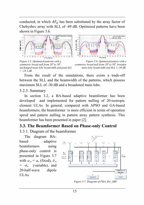
15
conducted, in which ��� has been substituted by the array factor of Chebyshev array with SLL of -49 dB. Optimized patterns have been shown in Figure 3.6.
Figure 3.5. Optimized patterns with a symmetric broad null from 200 to 500, unchanged main lobe beamwidth and peak SLL = -18.3 dB.
Figure 3.6. Optimized pattern with a symmetric broad null from 200 to 500, broaden
main lobe beamwidth and SLL ≤ -30 dB.
From the result of the simulations, there exists a trade-off between the SLL and the beamwidth of the patterns, which possess maximum SLL of -30 dB and a broadened main lobe.
3.2.3. Summary In section 3.2, a BA-based adaptive beamformer has been
developed and implemented for pattern nulling of 20-isotropic element ULAs. In general, compared with APSO and GA-based beamformers, the beamformer is more efficient in terms of operation speed and pattern nulling in pattern array pattern synthesis. This beamformer has been presented in paper [2].
3.3. The Beamformer Based on Phase-only Control
3.3.1. Diagram of the beamformer The diagram BA-
based adaptive beamformers using phase-only control is presented in Figure 3.7 with a-n = an (fixed), δ-n = -δn (variable), and 20-half-wave dipole ULAs.
Figure 3.7. Diagram of PHA_BA_ABF.

16
3.3.2. Numerical Results and Discussions Initial parameters for all algorithms as: pop: 1000 and ite: 20
(except for scenario 1). Simulation results are average values of Monte Carlo simulations with 1000 times for scenario 1, and 100 times for the others.
3.3.2.1. Convergence Characteristics In scenario 1 (like the
scenario in section 3.2.2.1), the initial population has been randomly generated, search value xi is in the range of –π to π. The simulation results in Figure 3.8 show the BA-based beamformer converges much faster than the APSO and GA ones.
Figure 3.9. Optimized pattern with a single null at 140.
Figure 3.10. Optimized pattern with three
nulls at -480, 200, and 400
3.3.2.2. Pattern with a Single Null In scenario 2 (like the scenario in section 3.2.2.2), variable phase
weights are in the range of -0.5 to 0.5 radian. Figure 3.9 presents optimized patterns with single null obtained by BA, APSO and GA at 140 with NDL of -87.15 dB. The BA pattern preserves almost all characteristics of the initial Chebyshev pattern except for a few side lobes with maximum SLL of -24.48 dB. Overall, the single null pattern optimized by the BA is better than that of the APSO and GA in terms of NDL.
3.3.2.3. Pattern with Multiple Nulls In scenario 3, BA-based beamformer has been used to separately
set multiple nulls at -480, 200, and 400 as presented in Figure 3.10.
Figure 3.8. Objective function comparisons of BA,
PSO, and GA.

17
All NDLs are deeper than -73 dB, all SLLs are lower than -24 dB, and HPBW roughly equals to that of Chebysev pattern. The BA pattern shows advantages over the APSO and GA ones in terms of NDL.
3.3.2.4. Pattern with a Broad Null In scenario 4, the pattern
with an imposed broad null at the target sector of [300, 400] has been obtained and illustrated in Figure 3.11. The results show BA pattern are better than APSO and GA ones in terms of NDL.
3.3.3. Summary In section 3.3, a BA-based beamformer has been developed and
implemented for DULA pattern nulling to suppress interferences. Furthermore, compared with APSO and GA-based beamformers, BA-based one is more efficient in terms of computation time and pattern nulling. This beamformer has been presented in paper [1].
3.4. The Beamformer Based on Complex-weight
Control
3.4.1. Diagram of the beamformer The diagram of BA-based
adaptive beamformers using complex-weight control has
been given in
Figure 3.12. ULAs with 20-isotropic element. Both the amplitude and the phase of weights are adjusted, in which a-n = an and δ-n = -δn.
Figure 3.11. Optimized pattern with a broad
null from 300 to 400.
Figure 3.12. Diagram of CW_BA_ABF.
18
3.4.2. Numerical Results and Discussions The initial parameters for all beamforming optimization
algorithms (BA, APSO, and GA) have been chosen for all investigation scenarios as: pop: 500; ite: 100; the variable phase of weight is in the range of -0.1 to 0.1 radian, and the variable amplitude is in the range of 0 to 1.
Simulation results are average values of Monte Carlo simulations with 1000 times for the first scenario, and 50 times for the others.
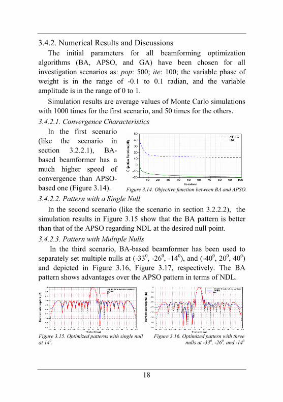
3.4.2.1. Convergence Characteristics In the first scenario
(like the scenario in section 3.2.2.1), BA-based beamformer has a much higher speed of convergence than APSO-based one (Figure 3.14).
3.4.2.2. Pattern with a Single Null
In the second scenario (like the scenario in section 3.2.2.2), the simulation results in Figure 3.15 show that the BA pattern is better than that of the APSO regarding NDL at the desired null point.
3.4.2.3. Pattern with Multiple Nulls In the third scenario, BA-based beamformer has been used to
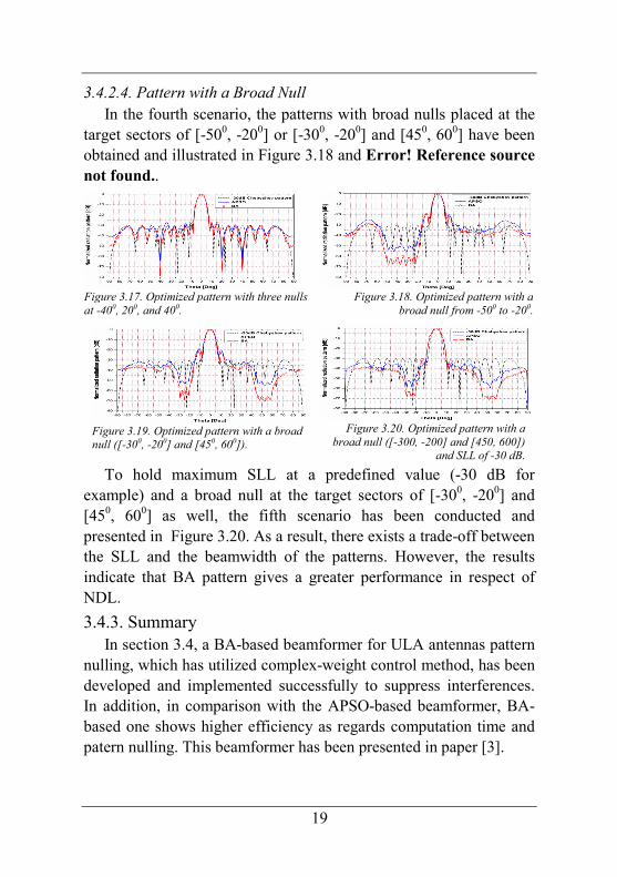
separately set multiple nulls at (-330, -260, -140), and (-400, 200, 400) and depicted in Figure 3.16, Figure 3.17, respectively. The BA pattern shows advantages over the APSO pattern in terms of NDL.
Figure 3.15. Optimized patterns with single null at 140.
Figure 3.16. Optimized pattern with three nulls at -330, -260, and -140
Figure 3.14. Objective function between BA and APSO.
19
3.4.2.4. Pattern with a Broad Null In the fourth scenario, the patterns with broad nulls placed at the
target sectors of [-500, -200] or [-300, -200] and [450, 600] have been obtained and illustrated in Figure 3.18 and Error! Reference source not found..
Figure 3.17. Optimized pattern with three nulls at -400, 200, and 400.
Figure 3.18. Optimized pattern with a broad null from -500 to -200.
Figure 3.19. Optimized pattern with a broad null ([-300, -200] and [450, 600]).
Figure 3.20. Optimized pattern with a
broad null ([-300, -200] and [450, 600]) and SLL of -30 dB.
To hold maximum SLL at a predefined value (-30 dB for example) and a broad null at the target sectors of [-300, -200] and [450, 600] as well, the fifth scenario has been conducted and presented in Figure 3.20. As a result, there exists a trade-off between the SLL and the beamwidth of the patterns. However, the results indicate that BA pattern gives a greater performance in respect of NDL.
3.4.3. Summary In section 3.4, a BA-based beamformer for ULA antennas pattern
nulling, which has utilized complex-weight control method, has been developed and implemented successfully to suppress interferences. In addition, in comparison with the APSO-based beamformer, BA-based one shows higher efficiency as regards computation time and patern nulling. This beamformer has been presented in paper [3].
20
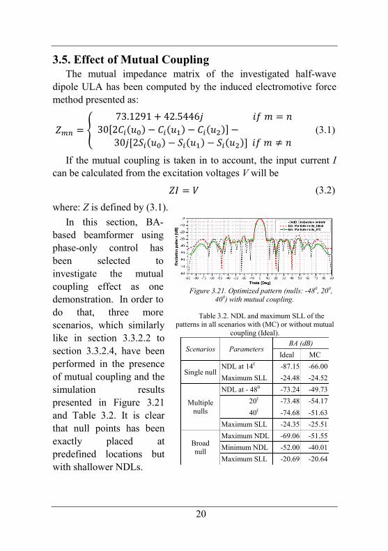
3.5. Effect of Mutual Coupling
The mutual impedance matrix of the investigated half-wave dipole ULA has been computed by the induced electromotive force method presented as:
a�� = b 73.1291 + 42.5446GR�j = "30�2k��l� − k��l�� − k��l��� −30G�2m��l� − m��l�� − m��l���R�j ≠ " (3.1)
If the mutual coupling is taken in to account, the input current I can be calculated from the excitation voltages V will be an = o (3.2)
where: Z is defined by (3.1).
In this section, BA-based beamformer using phase-only control has been selected to investigate the mutual coupling effect as one demonstration. In order to do that, three more scenarios, which similarly like in section 3.3.2.2 to section 3.3.2.4, have been performed in the presence of mutual coupling and the simulation results presented in Figure 3.21 and Table 3.2. It is clear that null points has been exactly placed at predefined locations but with shallower NDLs.
Figure 3.21. Optimized pattern (nulls: -480, 200,
400) with mutual coupling.
Table 3.2. NDL and maximum SLL of the patterns in all scenarios with (MC) or without mutual
coupling (Ideal).
Scenarios Parameters
BA (dB)
Ideal MC
Single null NDL at 140 -87.15 -66.00
Maximum SLL -24.48 -24.52
Multiple nulls
NDL at - 480 -73.24 -49.73
200 -73.48 -54.17
400 -74.68 -51.63
Maximum SLL -24.35 -25.51
Broad null
Maximum NDL -69.06 -51.55
Minimum NDL -52.00 -40.01
Maximum SLL -20.69 -20.64

21
3.6. Summary
For a quick reference, summary of three BA-based beamformers are presented as:
- AMP_BA_ABF: This beamformer is simple implementation and suitable for new design of smart antenna system duce to controlling only the amplitude of excitation of each array elements. The number of attenuators and controller are halved. The imposed nulls are symmetrical around the center of the pattern resulting in some unnecessary nulls. Extra cost are required to apply for the existing phased array system.
- PHA_BA_ABF: This beamformer is less complicated and attractive for the phased array systems without further expense. Its limitations are incapable of placing two symmetrical nulls and ineffective in the case of broad nulls (more than 100 as investigated with 20-element ULAs).
- CW_BA_ABF: This beamformer is the most flexible and effective. However, it is the most complicated one.
3.7. Chapter Conclusions
In this chapter, three different BA-based adaptive beamformers have been developed and implemented for pattern nulling of ULAs This pattern nulling is obtained by controlling amplitude-only, phase-only, and complex-weight (both the amplitude and the phase) of the excitation weight corresponding to each array element. The beamformers have shown the ability to place precisely single, multiple, and broad nulls at an arbitrary direction of interferences, suppress side lobes, and maintain predefined beamwidth. Additionally, the beamformer using phase-only nulling control has shown the ability of pattern nulling in the presence of mutual coupling and half-wave dipole elements. In general, the beamformers are much faster and more effective in terms of pattern nulling than GA and APSO-based ones.

22
Conclusions and Future Works
The objective of this work is to develop new BA-based adaptive beamformers for ULAs in smart antennas. It aims at improving the capability of interference suppression, which is an important application of beamformers for wireless communication systems. In order to do that, first of all, a general process to build adaptive beamformers for pattern nulling has been proposed. This general process includes six steps: (i) problem determination; (ii) array factor building; (iii) pattern nulling techniques; (iv) formation of objective function; (v) transformation of BA to adaptive beamforming algorithms; and (vi) development of adaptive beamformers
This process has been then applied to propose three different BA-based adaptive beamformers for interference suppression applications. These beamformers have used amplitude-only control, phase-only control, complex-weight control, respectively.
The performance of these beamformers has been verified in terms of the computational speed and the ability of pattern nulling in three following cases: single null at an arbitrary angle, multiple nulls, and a broad null (the maximum average NDL of 90.6 dB), which are the directions of interferences. Additionally, the beamformers show the ability to suppress side lobes at a low level while maintaining the predefined beamwidth. Furthermore, the beamformers are much faster and more effective in terms of pattern nulling than GA and APSO-based ones.
Main scientific contributions of the dissertation are:
(1) Proposal of a general process to build BA-based adaptive beamformers to suppress interferences for ULAs in smart antennas.
This general process includes six steps: problem determination; array factor building; pattern nulling techniques; formation of objective function; transformation

23
of BA to adaptive beamforming algorithms; and development of adaptive beamformers.
(2) Implementation of the general process to develop three types of BA-based adaptive beamformers to suppress interferences for ULAs using amplitude-only, phase-only, and complex-weight control techniques, respectively. To be more specific:
(i) Development of a BA-based adaptive beamformer for interference suppression using amplitude-only pattern nulling control. The beamformer for 20-isotropic element ULA has been successfully implemented and verified in terms of pattern nulling.
The implemented beamformer has shown the ability to place precisely a single null, multiple nulls, and a broad null at directions of interferences, to suppress sidelobes while maintaining the beamwidth.
Overall, the beamformer is simple to implement and the number of attenuators and computation time are halved.
(ii) Development of a BA-based adaptive beamformer for interference suppression using phase-only pattern nulling control. The beamformer for 20-dipole ULA, which is investigated with or without mutual coupling effect, has been successfully implemented and verified in terms of pattern nulling.
The results show that the nulls, which are a single null, multiple nulls, or a broad null, can be precisely imposed at directions of interferences while the pattern maintains the beamwidth and low sidelobe level (SLL).
In general, the proposal is close to the real applications, less complicated, and more attractive for the existing phased arrays, since the required controls are available at no extra cost and the computation time is reduced by half.
24
(iii) Development of an adaptive beamformer for interference suppression using complex-weight nulling control. The beamformer for 20-isotropic element ULA has been successfully implemented and verified in terms of pattern nulling.
The implemented beamformer has demonstrated the capability to place precisely single, multiple, and broad nulls at directions of interferences, to suppress sidelobes, and to maintain a predefined beamwidth.
Generally, this beamformer is the most flexible and effective compared to the others in (i) and (ii). However, the trade-off of this type of beamformer is that it is the most complicated one.
Future Works:
- Development of practical beamformers to be implemented in the next communication systems such as 5G mobile network.
Appendix
A. Smart Antennas B. Classical Optimization Techniques C. Software for Modeling Adaptive Beamforming in Smart Antennas D. Supported Simulation Results

25
Publications of the Dissertation
[1] T.V. Luyen and T.V.B. Giang (2017), "Interference Suppression of ULA Antennas by Phase-only Control Using Bat Algorithm", IEEE Antennas and Wireless Propagation Letters. vol. 16, pp. 3038 – 3042 (ISI – Q1)
[2] T.V. Luyen and T.V.B. Giang (2017), "Null-Steering Beamformer Using Bat Algorithm", Journal of Applied Computational Electromagnetic Society. Accepted for publication (ISI – Q3).
[3] T.V. Luyen and T.V.B. Giang (2017), "Bat Algorithm Based Beamformer for Interference Suppression by Controlling the Complex Weight", REV Journal on Electronics and Communications. Accepted for publication.
[4] T.V. Luyen and T.V.B. Giang (2017), Evaluation of Null-steering Beamformers Based on Phase-only or Amplitude-only Control Using Bat Algorithm, The 2017 Vietnam Japan Microwave Conference, Hanoi, pp. 34-40
Publications Related to the Dissertation
[5] T.V. Luyen and T.V.B. Giang (2015), Design and Implementation of FPGA based LMS Adaptive Beamformer for ULA Antennas, The 2015 Vietnam Japan Microwave Conference, Ho Chi Minh City, pp. 71-76.
[6] T.V. Luyen and T.V.B. Giang (2016), "Design of LMS Based Adaptive Beamformer for ULA Antennas", VNU Journal of Science: Comp. Science & Com. Eng. vol. 32(3), pp. 72-79.
[7] T.V. Luyen, P.D. Toai, and T.V.B. Giang, (2014), Nulling and Steering of Beams in Planar Anenna Arrays, The 2014 VIETNAM-JAPAN International Symposium on Antennas and Propagation, Hanoi, pp. 285-287.
[8] T.V. Luyen, T. D. Duc, and T.V.B. Giang, (2014), Reduction of Sidelobe Level in Planar Antenna Arrays, The 2013 VIETNAM-JAPAN International Symposium on Antennas and Propagation, Hanoi, pp. 283-284.
[9] T.V. Luyên, T.V.B. Giang (2014), Đề xuất mô hình hệ thống phần cứng để định dạng và điều khiển búp sóng cho các anten thông minh, Hội thảo quốc gia về điện tử, truyền thông và công nghệ thông tin, Nha Trang, pp. 190-193.


![[123doc.vn] luyen-noi-tieng-anh-nhu-nguoi-ban-ngu](https://static.fdocuments.us/doc/165x107/55c2917bbb61eb522b8b46aa/123docvn-luyen-noi-tieng-anh-nhu-nguoi-ban-ngu.jpg)
