Tollway Barrier Guidelines Examples Hands-On Workshop III July 2013 1.
131
Tollway Barrier Guidelines Examples Hands-On Workshop III July 2013 1
-
Upload
juliet-wilkins -
Category
Documents
-
view
215 -
download
0
description
Level 2 Example- Location 9 3
Transcript of Tollway Barrier Guidelines Examples Hands-On Workshop III July 2013 1.

Tollway Barrier GuidelinesExamples
Hands-On Workshop IIIJuly 2013
1

Each AOC should be analyzed separately.
a. Establish EOTW j. Warrant Analysis Level
b. Design Speed k. Lateral Offset of Barrier
c. Design ADT l. Upstream End of Guardrail
d. Length of Runout m. Upstream End of Barrier Wall
e. Shy Line Offset n. Downstream Terminal
f. Foreslope / Backslope o. Barrier Obstacle
g. Clear Zone p. Compare existing length to proposed
h. Clear Zone Adjustment q. Prepare warrant text and exhibits
i. Lateral Extent of the Area of Concern
2

Level 2 Example- Location 9
3

Level 2 Example- Location 9
4

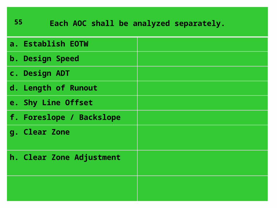
Each AOC shall be analyzed separately.
a. Establish EOTW
5

Each AOC shall be analyzed separately.
a. Establish EOTW
b. Design Speed
6

Each AOC shall be analyzed separately.
a. Establish EOTW
b. Design Speed
c. Design ADT
7

Each AOC shall be analyzed separately.
a. Establish EOTW
b. Design Speed
c. Design ADT
d. Length of Runout
8

d. Length of Runout
L2
Figure 5-39. Approach Barrier Layout Variables
LR
9
Level 2 Example- Location 9
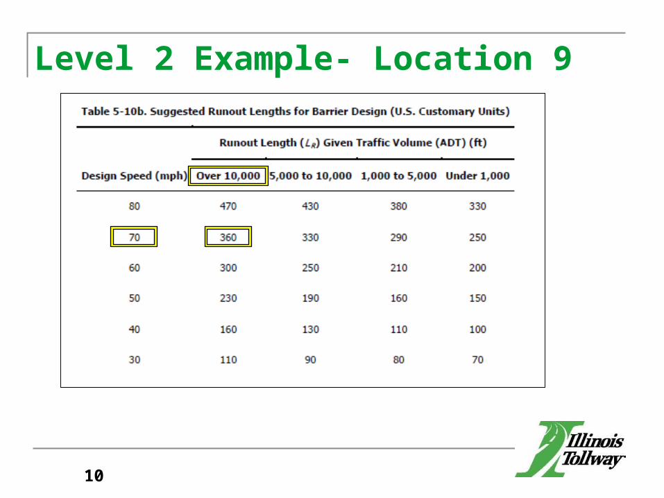
10

Each AOC shall be analyzed separately.
a. Establish EOTW
b. Design Speed
c. Design ADT
d. Length of Runout
e. Shy Line Offset
11

Each AOC shall be analyzed separately.
a. Establish EOTW
b. Design Speed
c. Design ADT
d. Length of Runout
e. Shy Line Offset
f. Foreslope / Backslope
12

Each AOC shall be analyzed separately.
a. Establish EOTW
b. Design Speed
c. Design ADT
d. Length of Runout
e. Shy Line Offset
f. Foreslope / Backslope
g. Clear Zone
13

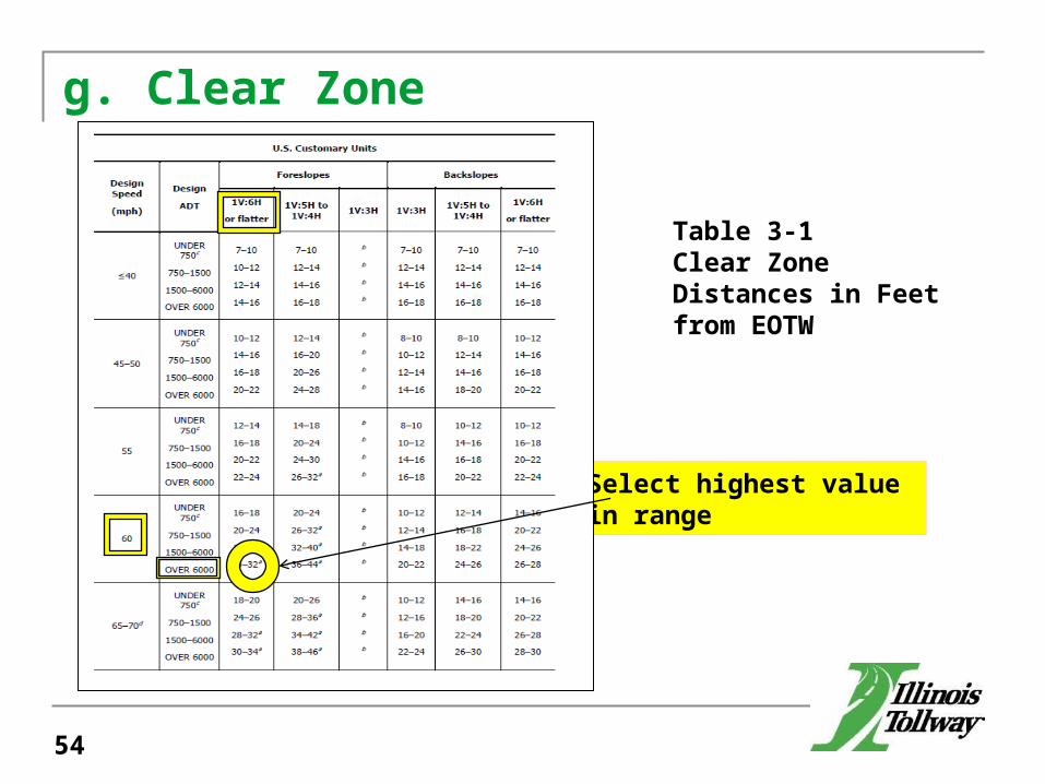
g. Clear Zone
Select highest value in range
Table 3-1Clear Zone Distances in Feet from EOTW
14

Each AOC shall be analyzed separately.
a. Establish EOTW
b. Design Speed
c. Design ADT
d. Length of Runout
e. Shy Line Offset
f. Foreslope / Backslope
g. Clear Zone
h. Clear Zone Adjustment
15

h. Clear Zone Adjustment
16

Each AOC shall be analyzed separately.
a. Establish EOTW
b. Design Speed
c. Design ADT
d. Length of Runout
e. Shy Line Offset
f. Foreslope / Backslope
g. Clear Zone
h. Clear Zone Adjustment
i. Lateral Extent of the Area of Concern
17

i. Lateral Extent of the Area of Concern
L2
Figure 5-39. Approach Barrier Layout Variables
LA
18

Level 2 Example- Location 9 Lateral Extent of the Area of ConcernLA =
LA = 23.9’ + 1.5’ = 25.4’
19

Each AOC shall be analyzed separately.
a. Establish EOTW j. Warrant Analysis Level
b. Design Speed
c. Design ADT
d. Length of Runout
e. Shy Line Offset
f. Foreslope / Backslope
g. Clear Zone
h. Clear Zone Adjustment
i. Lateral Extent of the Area of Concern
20
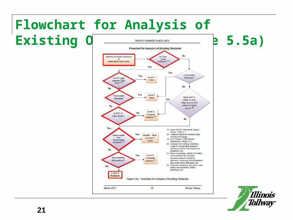
Flowchart for Analysis of Existing Obstacles (Figure 5.5a)
21

Each AOC shall be analyzed separately.
a. Establish EOTW j. Warrant Analysis Level
b. Design Speed k. Lateral Offset of Barrier
c. Design ADT
d. Length of Runout
e. Shy Line Offset
f. Foreslope / Backslope
g. Clear Zone
h. Clear Zone Adjustment
i. Lateral Extent of the Area of Concern
22

k. Lateral Offset of Barrier
L2
Figure 5-39. Approach Barrier Layout Variables
L2
23

Level 2 Example- Location 9 LA = 23.9’ + 1.5’ = 25.4’Lateral Offset of BarrierL2 =
L2 = 1’ + 11’ + 1’ = 13.0’
24

Each AOC shall be analyzed separately.
a. Establish EOTW j. Warrant Analysis Level
b. Design Speed k. Lateral Offset of Barrier
c. Design ADT l. Upstream End of Guardrail
d. Length of Runout
e. Shy Line Offset
f. Foreslope / Backslope
g. Clear Zone
h. Clear Zone Adjustment
i. Lateral Extent of the Area of Concern
25

Level 2 Example- Location 9 LA = 25.4’L2 = 13.0’Y=Y = L2 + 0.75’Y = 13.0’ + 0.75’Y = 13.75’
26

l. Upstream End of Guardrail
L2
Figure 5-39. Approach Barrier Layout Variables
X= (LA – Y) / (LA / LR )LA
LR
LA - Y X
27

Level 2 Example- Location 9 LA = 25.4’L2 = 13.0’Y = 13.75’LR = 360.0’
Length of Need – FormulaSolve for XX = (LA – Y) / (LA / LR)X = (25.4’ – 13.75’) / (25.4’ / 360.0’)X = 165.12’
28

Level 2 Example- Location 9 ObstacleSFSouthface_Foundation_Station = SFSF = (3945+98.50)LAOC = Length of AOC = 3.0’
29

l. Upstream End of Guardrail
L2
Figure 5-39. Approach Barrier Layout Variables
Point of Need
30

Level 2 Example- Location 9 Point of Need PON = SF – X PON = (3945+98.50) – 165.12’PON = (3944+33.38)
Length of Need = LON = X + LAOC
LON = 165.12’ + 3.0’LON = 168.12’
31
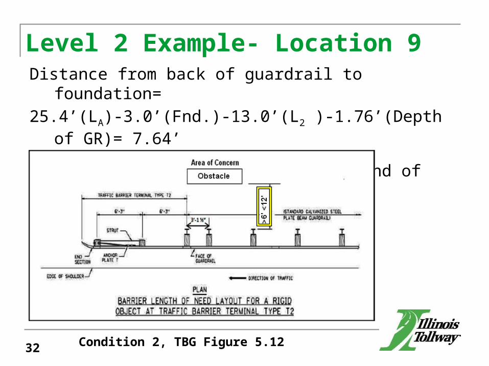
Level 2 Example- Location 9 Distance from back of guardrail to foundation=25.4’(LA)-3.0’(Fnd.)-13.0’(L2 )-1.76’(Depth of GR)= 7.64’
Therefore, LON ends at downstream end of obstacle.
Condition 2, TBG Figure 5.1232

Level 2 Example- Location 9 TerminalsTerminal = Type T2T2 = 12.5’ (does not count toward length of need)Terminal = Type T1 (Special) T1 = 50.0’ (37.5’ counts toward length of need)Barrier Limits DeterminationLength of Guardrail LGuardrail = LON – T1LGuardrail = 168.12’ – 37.5’
LGuardrail = 130.62’ LGuardrail, R = LGuardrail (Round up to the nearest 12.5’ increment)
LGuardrail, R = 137.5’
33

Each AOC shall be analyzed separately.
a. Establish EOTW j. Warrant Analysis Level
b. Design Speed k. Lateral Offset of Barrier
c. Design ADT l. Upstream End of Guardrail
d. Length of Runout m. Upstream End of Barrier Wall
e. Shy Line Offset
f. Foreslope / Backslope
g. Clear Zone
h. Clear Zone Adjustment
i. Lateral Extent of the Area of Concern
34

Each AOC shall be analyzed separately.
a. Establish EOTW j. Warrant Analysis Level
b. Design Speed k. Lateral Offset of Barrier
c. Design ADT l. Upstream End of Guardrail
d. Length of Runout m. Upstream End of Barrier Wall
e. Shy Line Offset n. Downstream Terminal
f. Foreslope / Backslope
g. Clear Zone
h. Clear Zone Adjustment
i. Lateral Extent of the Area of Concern
35

Level 2 Example- Location 9 T2End_Station = SF + LAOC + T2T2End_Station = (3945+98.50) + 3’ + 12.5’T2End_Station = (3946+14.00)GREnd_Station = Begin T2Station = End T2Station – 12.5’GREnd_Station = (3946+14.00) – 12.5’GREnd_Station = (3946+01.50)
GRBegin_Station = GREnd_Station – LGuardrail,R
GRBegin_Station = (3946+01.50) – 137.5’GRBegin_Station = (3944+64.00)T1Begin_Station = GRBegin_Station – 50’T1Station = (3944+64.00) – 50’T1Begin_Station = (3944+14.00)
36

Each AOC shall be analyzed separately.
a. Establish EOTW j. Warrant Analysis Level
b. Design Speed k. Lateral Offset of Barrier
c. Design ADT l. Upstream End of Guardrail
d. Length of Runout m. Upstream End of Barrier Wall
e. Shy Line Offset n. Downstream Terminal
f. Foreslope / Backslope o. Barrier Obstacle
g. Clear Zone
h. Clear Zone Adjustment
i. Lateral Extent of the Area of Concern
37

Barrier Limits Check
12.5’ < |PON- T1Begin_Station|< 25’12.5’ < |(3944+33.38) – (3944+14.00)|< 25’12.5’ < 19.38’ < 25’
38

Each AOC shall be analyzed separately.
a. Establish EOTW j. Warrant Analysis Level
b. Design Speed k. Lateral Offset of Barrier
c. Design ADT l. Upstream End of Guardrail
d. Length of Runout m. Upstream End of Barrier Wall
e. Shy Line Offset n. Downstream Terminal
f. Foreslope / Backslope o. Barrier Obstacle
g. Clear Zone p. Compare existing length to proposed
h. Clear Zone Adjustment
i. Lateral Extent of the Area of Concern
39

Each AOC shall be analyzed separately.
a. Establish EOTW j. Warrant Analysis Level
b. Design Speed k. Lateral Offset of Barrier
c. Design ADT l. Upstream End of Guardrail
d. Length of Runout m. Upstream End of Barrier Wall
e. Shy Line Offset n. Downstream Terminal
f. Foreslope / Backslope o. Barrier Obstacle
g. Clear Zone p. Compare existing length to proposed
h. Clear Zone Adjustment q. Prepare warrant text and exhibits
i. Lateral Extent of the Area of Concern
40

Level 2 Example – Location 9 – Site Plan
41

Questions?
42

Level 2 Example- Location 17
43

Level 2 Example- Location 17
44
Notes: 1. There is a crash wall in
front of the bridge piers.2. Regrading of the bridge
cone is not a feasible alternative.
Each AOC shall be analyzed separately.
a. Establish EOTW
45

Each AOC shall be analyzed separately.
a. Establish EOTW
b. Design Speed
46

Each AOC shall be analyzed separately.
a. Establish EOTW
b. Design Speed
c. Design ADT
47

Each AOC shall be analyzed separately.
a. Establish EOTW
b. Design Speed
c. Design ADT
d. Length of Runout
48

d. Length of Runout
L2
Figure 5-39. Approach Barrier Layout Variables
LR
49

d. Length of Runout
50

Each AOC shall be analyzed separately.
a. Establish EOTW
b. Design Speed
c. Design ADT
d. Length of Runout
e. Shy Line Offset
51

Each AOC shall be analyzed separately.
a. Establish EOTW
b. Design Speed
c. Design ADT
d. Length of Runout
e. Shy Line Offset
f. Foreslope / Backslope
52

Each AOC shall be analyzed separately.
a. Establish EOTW
b. Design Speed
c. Design ADT
d. Length of Runout
e. Shy Line Offset
f. Foreslope / Backslope
g. Clear Zone
53
g. Clear Zone
Select highest value in range
Table 3-1Clear Zone Distances in Feet from EOTW
54
Each AOC shall be analyzed separately.
a. Establish EOTW
b. Design Speed
c. Design ADT
d. Length of Runout
e. Shy Line Offset
f. Foreslope / Backslope
g. Clear Zone
h. Clear Zone Adjustment
55

h. Clear Zone Adjustment
56

Level 2 Example- Location 17
Adjusted Clear Zone= 32’ x 1.2= 38.4’
57

Each AOC shall be analyzed separately.
a. Establish EOTW
b. Design Speed
c. Design ADT
d. Length of Runout
e. Shy Line Offset
f. Foreslope / Backslope
g. Clear Zone
h. Clear Zone Adjustment
i. Lateral Extent of the Area of Concern
58

i. Lateral Extent of the Area of Concern
L2
Figure 5-39. Approach Barrier Layout Variables
LA
59

Level 2 Example- Location 17
Lateral Extent of the Area of ConcernLA =LA = 32’ x 1.2LA = 38.4’
60

Each AOC shall be analyzed separately.
a. Establish EOTW j. Warrant Analysis Level
b. Design Speed
c. Design ADT
d. Length of Runout
e. Shy Line Offset
f. Foreslope / Backslope
g. Clear Zone
h. Clear Zone Adjustment
i. Lateral Extent of the Area of Concern
61

Flowchart for Analysis of Existing Obstacles (Figure 5.5a)
62

Each AOC shall be analyzed separately.
a. Establish EOTW j. Warrant Analysis Level
b. Design Speed k. Lateral Offset of Barrier
c. Design ADT
d. Length of Runout
e. Shy Line Offset
f. Foreslope / Backslope
g. Clear Zone
h. Clear Zone Adjustment
i. Lateral Extent of the Area of Concern
63

k. Lateral Offset of Barrier
L2
Figure 5-39. Approach Barrier Layout Variables
L2
64

Level 2 Example- Location 17
LA = 38.4’L2 =L2 = 12.0’ (11’ + 1’)
65

Each AOC shall be analyzed separately.
a. Establish EOTW j. Warrant Analysis Level
b. Design Speed k. Lateral Offset of Barrier
c. Design ADT l. Upstream End of Guardrail
d. Length of Runout
e. Shy Line Offset
f. Foreslope / Backslope
g. Clear Zone
h. Clear Zone Adjustment
i. Lateral Extent of the Area of Concern
66

Level 2 Example- Location 17
LA = 38.4’Lateral Offset of BarrierL2 = 12.0’ (11’ + 1’)Y = Y = L2 + 0.75’Y = 12.0’ + 0.75’Y = 12.75’
67

l. Upstream End of Guardrail
< LR
LA
L2
Y
X
Figure 5-48. Example of Barrier Design for Fixed Object on Horizontal Curve
Graphical Determination of “X”
68
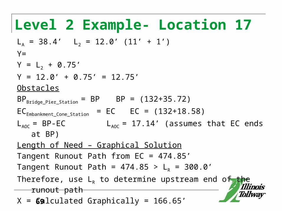
Level 2 Example- Location 17LA = 38.4’ L2 = 12.0’ (11’ + 1’) Y=Y = L2 + 0.75’Y = 12.0’ + 0.75’ = 12.75’ ObstaclesBPBridge_Pier_Station = BP BP = (132+35.72)ECEmbankment_Cone_Station = EC EC = (132+18.58) LAOC = BP-EC LAOC = 17.14’ (assumes that EC ends at BP)Length of Need – Graphical SolutionTangent Runout Path from EC = 474.85’Tangent Runout Path = 474.85 > LR = 300.0’Therefore, use LR to determine upstream end of the runout pathX = Calculated Graphically = 166.65’
69

Level 2 Example- Location 17
Point of Need = PON
PON = EC – XPON = (132+18.58) – 166.65’PON = (130+51.93)Length of Need = LON LON = X + LAOC
LON = 166.65’ + 17.14’LON = 183.79’
70

Each AOC shall be analyzed separately.
a. Establish EOTW j. Warrant Analysis Level
b. Design Speed k. Lateral Offset of Barrier
c. Design ADT l. Upstream End of Guardrail
d. Length of Runout m. Upstream End of Barrier Wall
e. Shy Line Offset
f. Foreslope / Backslope
g. Clear Zone
h. Clear Zone Adjustment
i. Lateral Extent of the Area of Concern
71

Each AOC shall be analyzed separately.
a. Establish EOTW j. Warrant Analysis Level
b. Design Speed k. Lateral Offset of Barrier
c. Design ADT l. Upstream End of Guardrail
d. Length of Runout m. Upstream End of Barrier Wall
e. Shy Line Offset n. Downstream Terminal
f. Foreslope / Backslope
g. Clear Zone
h. Clear Zone Adjustment
i. Lateral Extent of the Area of Concern
72

Level 2 Example- Location 17Terminals
Terminal = Type T6B T6B = 43.15’ (counts toward length of need)Terminal = Type T1 (Special) = T1 = 50.0’ (37.5’ counts toward length of need)Barrier Limits DeterminationLength of Guardrail
LGuardrail = LON – T6B – T1LGuardrail = 183.79’ – 43.15’ – 37.5’
LGuardrail = 103.14’LGuardrail, R = LGuardrail (Round up to the neareast 12.5’ increment)
LGuardrail, R = 112.5’
73

Level 2 Example- Location 17T6BEnd_Station = BPT6BEnd_Station = (132+35.72) GREnd_Station = End T6BStation – 43.15’GREnd_Station = (132+35.72) – 43.15’GREnd_Station = (131+92.57) GRBegin_Station = GREnd_Station – LGuardrail,R
GRBegin_Station = (131+92.57) – 112.5’GRBegin_Station = (130+80.07) T1Begin_Station = GRBegin_Station – 50’T1Begin_Station = (130+80.07) – 50’T1Begin_Station = (130+30.07)
74

Barrier Limits Check:
12.5’ < |PON – T1Begin_Station |< 25’
12.5’ < |(130+51.93) – (130+30.07)| < 25’
12.5’ < 21.86’ < 25’
75

Each AOC shall be analyzed separately.
a. Establish EOTW j. Warrant Analysis Level
b. Design Speed k. Lateral Offset of Barrier
c. Design ADT l. Upstream End of Guardrail
d. Length of Runout m. Upstream End of Barrier Wall
e. Shy Line Offset n. Downstream Terminal
f. Foreslope / Backslope o. Barrier Obstacle
g. Clear Zone
h. Clear Zone Adjustment
i. Lateral Extent of the Area of Concern
76

Each AOC shall be analyzed separately.
a. Establish EOTW j. Warrant Analysis Level
b. Design Speed k. Lateral Offset of Barrier
c. Design ADT l. Upstream End of Guardrail
d. Length of Runout m. Upstream End of Barrier Wall
e. Shy Line Offset n. Downstream Terminal
f. Foreslope / Backslope o. Barrier Obstacle
g. Clear Zone p. Compare existing length to proposed
h. Clear Zone Adjustment
i. Lateral Extent of the Area of Concern
77

Each AOC shall be analyzed separately.
a. Establish EOTW j. Warrant Analysis Level
b. Design Speed k. Lateral Offset of Barrier
c. Design ADT l. Upstream End of Guardrail
d. Length of Runout m. Upstream End of Barrier Wall
e. Shy Line Offset n. Downstream Terminal
f. Foreslope / Backslope o. Barrier Obstacle
g. Clear Zone p. Compare existing length to proposed
h. Clear Zone Adjustment q. Prepare warrant text and exhibits
i. Lateral Extent of the Area of Concern
78

Level 2 Example- Location 17 – Site Plan
79

Questions?
80

Example-Speed Profile
81

Site Plan
82

Acceleration Table
Table 10-3Minimum Acceleration Lengths for Entrance Terminals with Flat Grades of Two Percent or Less
83

Example-Speed Profile-Site Plan
30MPH
40MPH
50MPH
60MPH
70MPH
84

Level 3 Example – Overhead Sign Truss
85

Level 3 Example – Plan
86

Flowchart for Analysis of Proposed Obstacles (Figure 5.5b)
87

New Overhead Sign Truss (Span and Cantilever) Article 5.5.9 The Designer shall perform a Level 3 Analysis to
determine the most cost-effective design for all new overhead sign installations. The alternatives at minimum to evaluate shall include: (1) base condition – shortest span or arm with shielding; (2) span or arm length which places foundation outside defined clear zone with no shielding or if clear zone is undefined places foundation such that the criteria in Table 5.6.1 is met; (3) longer span or arm which places foundation well outside the clear zone with no shielding.
88

Level 3 Example – Overhead Sign TrussAnalyze 4 Alternatives for Sign Foundation
(Assumes Clear Zone is defined)1. Base Condition: Foundation Shielded by
Guardrail2. Foundation Beyond Clear Zone, not shielded3. Foundation on Backslope, not shielded4. Foundation on Backslope, not shielded (max.
length truss)
89

Level 3 Example – Plan
90

Level 3 Example – Cross Section 91

Level 3 Example – Cross Section 92

Level 3 Example – Cross Section 93

Level 3 Example – Cross Section 94

Sign Structure Foundation
95

Level 3 Example – Feature Sketch
96
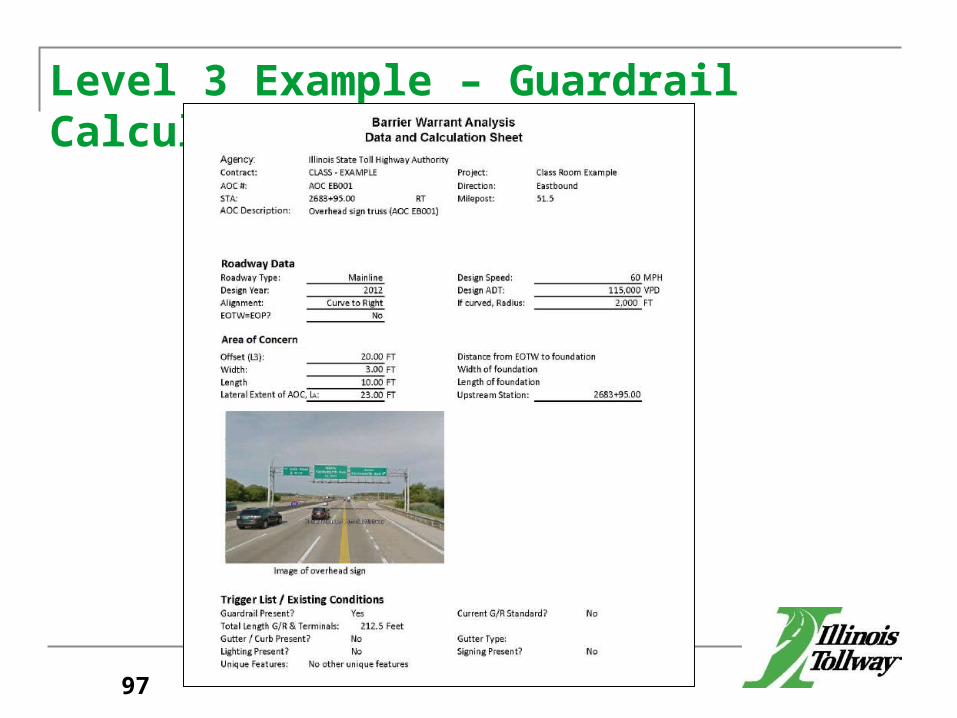
Level 3 Example – Guardrail Calculation
97

Level 3 Example – Guardrail Calculation
98

Level 3 Example – Guardrail Calculation
99
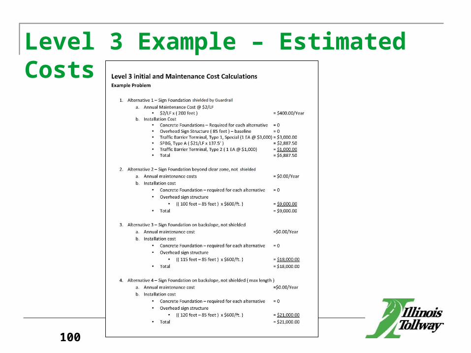
Level 3 Example – Estimated Costs
100

Cost Tab
101

Highway Tab
102

Segments Tab
103

Features Tab
104

View Pulldown
105

View/ Crash Cost
106

View/ Crash Cost/ KABCO
107

Options/ Units
108

Option/ Edit Feature
109
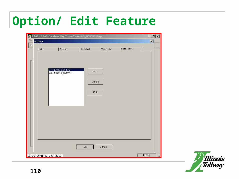
Option/ Edit Feature
110

Edit Feature
111

Features/ Category
112

Features / Category/ User Defined
113

Feature/ Types
114

RSAP Output
115

RSAP Output
116

RSAP Output
117

RSAP Output
118

RSAP Output
119

RSAP Output
2 vs. 33 vs. 44 vs. 1
120
3 is better4 is better4 is better

AOC’s in Close
Proximity

14+25
Culvert - AOC #1
14+00 17+22
Cantilever Sign- AOC #2
15+70
16+12.517+05
Upstream Terminal End
18+30
18+42.5
Downstream Terminal End
Upstream Terminal End Downstream
Terminal End
92.5’Gap
Total Length of Need = 405’
EOTW
AOC’s in Close Proximity
122
PON PON
16+00 18+27
14+05

Example- AOC Table FormatAOC# UPSTREAM
US TERMPON DS End of
GuardrailDOWNSTREAM
DSTERM
GAP(FT)
OVERLAP(FT)
1 14+00 14+25 16+00 16+12.50
92.50 ---
2 17+05 17+22 18+30 18+42.50
123

Summary CalculationLON = AOC #2 DS End of GR – AOC #1 PON = (18+30)-(14+25) = 405’TerminalsDS Terminal= TBT Type T2=T2US Terminal= TBT Type T1=T1
124
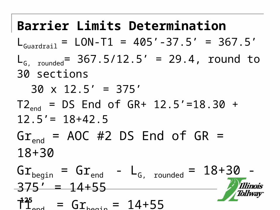
Barrier Limits DeterminationLGuardrail = LON-T1 = 405’-37.5’ = 367.5’LG, rounded= 367.5/12.5’ = 29.4, round to 30 sections
30 x 12.5’ = 375’T2end = DS End of GR+ 12.5’=18.30 + 12.5’= 18+42.5
Grend = AOC #2 DS End of GR = 18+30Grbegin = Grend - LG, rounded = 18+30 - 375’ = 14+55T1end = Grbegin = 14+55T1begin = T1end - 50’ = 14+55-50’ = 14+05
125

Barrier Limits Check12.5’ < AOC #1 PON – T1begin < 25’AOC #1 PON – T1begin
14+25-14.05= 20’
Provide a Summary Site Plan
126

14+25
Culvert - AOC #1
14+00 17+72
Cantilever Sign- AOC #2
15+70
16+12.517+55
Upstream Terminal End
18+80
18+92.5
Downstream Terminal End
Upstream Terminal End
Downstream Terminal End
142.5’Gap
EOTW
AOC’s in Close Proximity
127
PON PON
16+00 18+77
Length of Need
Length of Need

14+25
Culvert - AOC #1
14+12.5 16+22
Cantilever Sign- AOC #2
15+70
16+12.5
16+05Upstream Terminal End
17+30
17+42.5
Downstream Terminal End
Upstream Terminal End Downstream
Terminal End
7.5’ Overlap
Total Length of Need
EOTW
AOC’s in Close Proximity
128
PON PON
16+00 17+27
14+17.5

Example- AOC Summary Table FormatLEGENDPOINT OF NEED STATIONDOWNSTREAM END OF GUARDRAIL STATION
AOC SUMMARY TABLEAOC 1 15+00 26+00AOC 2 15+00 22+50AOC 3 16+25 27+00AOC 4 19+00 23+00 SUMMARY 15+00 27+00TOTAL LON 15+00 to 27+00 = 1,200 FT

AOC- Color Coded System

Questions?
131