TOLERANCES, DEVIATIONS AND FITS · to the international standard ISO 286. 2. Determination of...
4
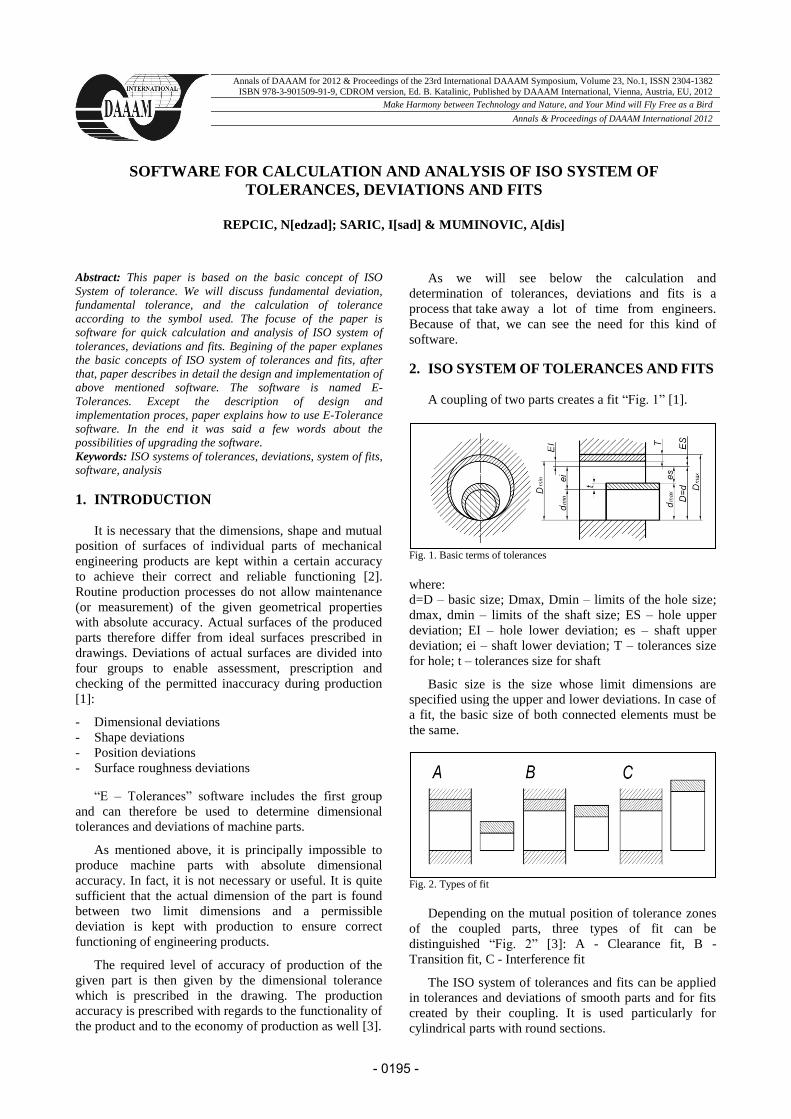
Annals of DAAAM for 2012 & Proceedings of the 23rd International DAAAM Symposium, Volume 23, No.1, ISSN 2304-1382 ISBN 978-3-901509-91-9, CDROM version, Ed. B. Katalinic, Published by DAAAM International, Vienna, Austria, EU, 2012 Make Harmony between Technology and Nature, and Your Mind will Fly Free as a Bird Annals & Proceedings of DAAAM International 2012 SOFTWARE FOR CALCULATION AND ANALYSIS OF ISO SYSTEM OF TOLERANCES, DEVIATIONS AND FITS REPCIC, N[edzad]; SARIC, I[sad] & MUMINOVIC, A[dis] Abstract: This paper is based on the basic concept of ISO System of tolerance. We will discuss fundamental deviation, fundamental tolerance, and the calculation of tolerance according to the symbol used. The focuse of the paper is software for quick calculation and analysis of ISO system of tolerances, deviations and fits. Begining of the paper explanes the basic concepts of ISO system of tolerances and fits, after that, paper describes in detail the design and implementation of above mentioned software. The software is named E- Tolerances. Except the description of design and implementation proces, paper explains how to use E-Tolerance software. In the end it was said a few words about the possibilities of upgrading the software. Keywords: ISO systems of tolerances, deviations, system of fits, software, analysis 1. INTRODUCTION It is necessary that the dimensions, shape and mutual position of surfaces of individual parts of mechanical engineering products are kept within a certain accuracy to achieve their correct and reliable functioning [2]. Routine production processes do not allow maintenance (or measurement) of the given geometrical properties with absolute accuracy. Actual surfaces of the produced parts therefore differ from ideal surfaces prescribed in drawings. Deviations of actual surfaces are divided into four groups to enable assessment, prescription and checking of the permitted inaccuracy during production [1]: - Dimensional deviations - Shape deviations - Position deviations - Surface roughness deviations “E – Tolerances” software includes the first group and can therefore be used to determine dimensional tolerances and deviations of machine parts. As mentioned above, it is principally impossible to produce machine parts with absolute dimensional accuracy. In fact, it is not necessary or useful. It is quite sufficient that the actual dimension of the part is found between two limit dimensions and a permissible deviation is kept with production to ensure correct functioning of engineering products. The required level of accuracy of production of the given part is then given by the dimensional tolerance which is prescribed in the drawing. The production accuracy is prescribed with regards to the functionality of the product and to the economy of production as well [3]. As we will see below the calculation and determination of tolerances, deviations and fits is a process that take away a lot of time from engineers. Because of that, we can see the need for this kind of software. 2. ISO SYSTEM OF TOLERANCES AND FITS A coupling of two parts creates a fit “Fig. 1” [1]. Fig. 1. Basic terms of tolerances where: d=D – basic size; Dmax, Dmin – limits of the hole size; dmax, dmin – limits of the shaft size; ES – hole upper deviation; EI – hole lower deviation; es – shaft upper deviation; ei – shaft lower deviation; T – tolerances size for hole; t – tolerances size for shaft Basic size is the size whose limit dimensions are specified using the upper and lower deviations. In case of a fit, the basic size of both connected elements must be the same. Fig. 2. Types of fit Depending on the mutual position of tolerance zones of the coupled parts, three types of fit can be distinguished “Fig. 2” [3]: A - Clearance fit, B - Transition fit, C - Interference fit The ISO system of tolerances and fits can be applied in tolerances and deviations of smooth parts and for fits created by their coupling. It is used particularly for cylindrical parts with round sections. - 0195 -
Transcript of TOLERANCES, DEVIATIONS AND FITS · to the international standard ISO 286. 2. Determination of...
Annals of DAAAM for 2012 & Proceedings of the 23rd International DAAAM Symposium, Volume 23, No.1, ISSN 2304-1382
ISBN 978-3-901509-91-9, CDROM version, Ed. B. Katalinic, Published by DAAAM International, Vienna, Austria, EU, 2012
Make Harmony between Technology and Nature, and Your Mind will Fly Free as a Bird
Annals & Proceedings of DAAAM International 2012
SOFTWARE FOR CALCULATION AND ANALYSIS OF ISO SYSTEM OF
TOLERANCES, DEVIATIONS AND FITS
REPCIC, N[edzad]; SARIC, I[sad] & MUMINOVIC, A[dis]
Abstract: This paper is based on the basic concept of ISO
System of tolerance. We will discuss fundamental deviation,
fundamental tolerance, and the calculation of tolerance
according to the symbol used. The focuse of the paper is
software for quick calculation and analysis of ISO system of
tolerances, deviations and fits. Begining of the paper explanes
the basic concepts of ISO system of tolerances and fits, after
that, paper describes in detail the design and implementation of
above mentioned software. The software is named E-
Tolerances. Except the description of design and
implementation proces, paper explains how to use E-Tolerance
software. In the end it was said a few words about the
possibilities of upgrading the software.
Keywords: ISO systems of tolerances, deviations, system of fits,
software, analysis
1. INTRODUCTION
It is necessary that the dimensions, shape and mutual
position of surfaces of individual parts of mechanical
engineering products are kept within a certain accuracy
to achieve their correct and reliable functioning [2].
Routine production processes do not allow maintenance
(or measurement) of the given geometrical properties
with absolute accuracy. Actual surfaces of the produced
parts therefore differ from ideal surfaces prescribed in
drawings. Deviations of actual surfaces are divided into
four groups to enable assessment, prescription and
checking of the permitted inaccuracy during production
[1]:
- Dimensional deviations
- Shape deviations
- Position deviations
- Surface roughness deviations
“E – Tolerances” software includes the first group
and can therefore be used to determine dimensional
tolerances and deviations of machine parts.
As mentioned above, it is principally impossible to
produce machine parts with absolute dimensional
accuracy. In fact, it is not necessary or useful. It is quite
sufficient that the actual dimension of the part is found
between two limit dimensions and a permissible
deviation is kept with production to ensure correct
functioning of engineering products.
The required level of accuracy of production of the
given part is then given by the dimensional tolerance
which is prescribed in the drawing. The production
accuracy is prescribed with regards to the functionality of
the product and to the economy of production as well [3].
As we will see below the calculation and
determination of tolerances, deviations and fits is a
process that take aw ay a lot of time from engineers.
Because of that, we can see the need for this kind of
software.
2. ISO SYSTEM OF TOLERANCES AND FITS
A coupling of two parts creates a fit “Fig. 1” [1].
Fig. 1. Basic terms of tolerances
where:
d=D – basic size; Dmax, Dmin – limits of the hole size;
dmax, dmin – limits of the shaft size; ES – hole upper
deviation; EI – hole lower deviation; es – shaft upper
deviation; ei – shaft lower deviation; T – tolerances size
for hole; t – tolerances size for shaft
Basic size is the size whose limit dimensions are
specified using the upper and lower deviations. In case of
a fit, the basic size of both connected elements must be
the same.
Fig. 2. Types of fit
Depending on the mutual position of tolerance zones
of the coupled parts, three types of fit can be
distinguished “Fig. 2” [3]: A - Clearance fit, B -
Transition fit, C - Interference fit
The ISO system of tolerances and fits can be applied
in tolerances and deviations of smooth parts and for fits
created by their coupling. It is used particularly for
cylindrical parts with round sections.
- 0195 -
Tolerances and deviations in this standard can also be applied in smooth parts of other sections. Similarly, the system can be used for coupling (fits) of cylindrical parts and for fits with parts having two parallel surfaces (e.g. fits of keys in grooves). The term "shaft", used in this standard has a wide meaning and serves for specification of all outer elements of the part, including those elements which do not have cylindrical shapes. Also, the term "hole" can be used for specification of all inner elements regardless of their shape [3].
2.1 Tolerances of a basic size for specific tolerances grade
The tolerance of a size is defined as the difference between the upper and lower limit dimensions of the part. In order to meet the requirements of various production branches for accuracy of the product, the system ISO implements 20 grades of accuracy [3].
Tolerances grade Place of use
IT01 to IT6 For production of gauges and
measuring instruments
IT5 to IT12 For fits in precision and general
engineering
IT11 to IT16 For production of semi-products
IT16 to IT18 For structures
IT11 to IT18 For specification of limit deviations
of non-tolerated dimensions
Tab. 1. Field of use of individual tolerances of the system ISO
Each of the tolerances of this system is marked "IT"
with attached grade of accuracy (IT01, IT0, IT1 ... IT18). 2.2 Hole and saft tolerances zone
The tolerance zone is defined as a spherical zone
limited by the upper and lower limit dimensions of the
part. The tolerance zone is therefore determined by the
amount of the tolerance and its position related to the
basic size.
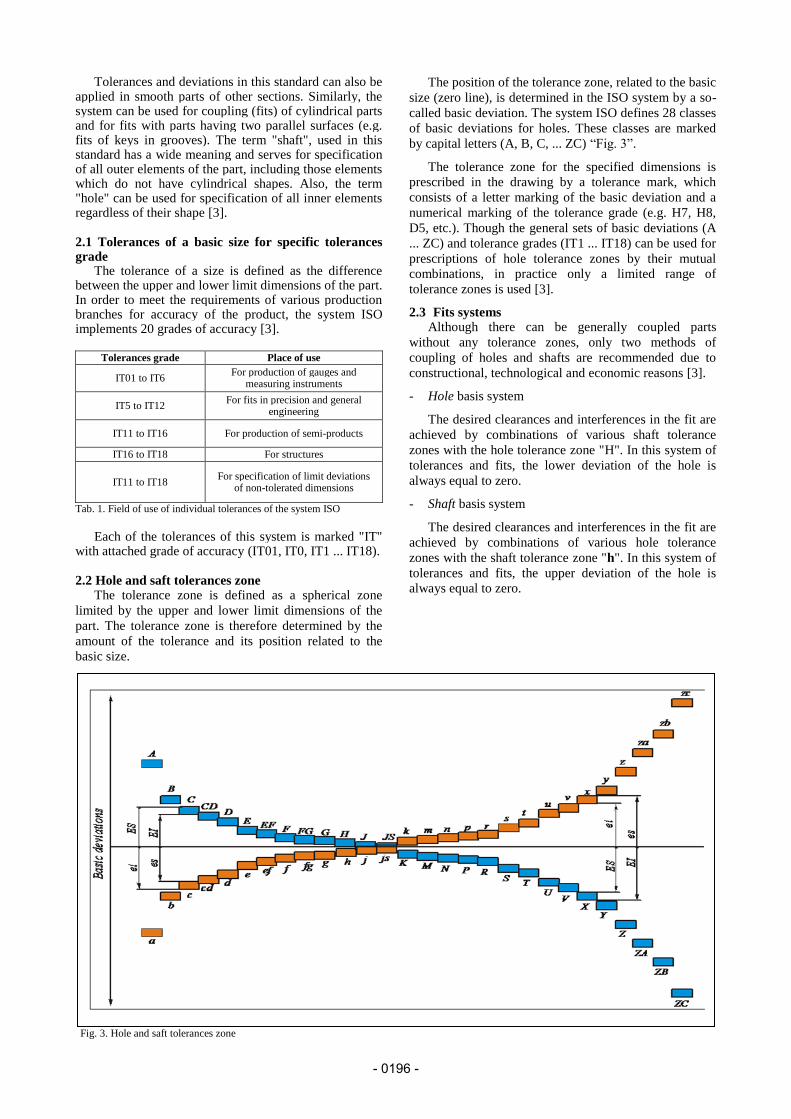
The position of the tolerance zone, related to the basic
size (zero line), is determined in the ISO system by a so-
called basic deviation. The system ISO defines 28 classes
of basic deviations for holes. These classes are marked
by capital letters (A, B, C, ... ZC) “Fig. 3”.
The tolerance zone for the specified dimensions is
prescribed in the drawing by a tolerance mark, which
consists of a letter marking of the basic deviation and a
numerical marking of the tolerance grade (e.g. H7, H8,
D5, etc.). Though the general sets of basic deviations (A
... ZC) and tolerance grades (IT1 ... IT18) can be used for
prescriptions of hole tolerance zones by their mutual
combinations, in practice only a limited range of
tolerance zones is used [3].
2.3 Fits systems Although there can be generally coupled parts
without any tolerance zones, only two methods of
coupling of holes and shafts are recommended due to
constructional, technological and economic reasons [3].
- Hole basis system
The desired clearances and interferences in the fit are
achieved by combinations of various shaft tolerance
zones with the hole tolerance zone "H". In this system of
tolerances and fits, the lower deviation of the hole is
always equal to zero.
- Shaft basis system
The desired clearances and interferences in the fit are
achieved by combinations of various hole tolerance
zones with the shaft tolerance zone "h". In this system of
tolerances and fits, the upper deviation of the hole is
always equal to zero.
Fig. 3. Hole and saft tolerances zone
- 0196 -

3. SOFTWARE FOR CALCULATION AND
ANALYSIS OF ISO SYSTEM OF
TOLERANCES, DEVIATIONS AND FITS Using E-Tolerances software the following tasks can
be solved:
1. Selection of suitable fits of machine parts according
to the international standard ISO 286.
2. Determination of dimensional tolerances and
deviations of machine parts according to the
international standard ISO 286.
3. Selection of preferred fits of machine parts and
determination of their dimensional tolerances and
deviations
4. Automatic design of a fit for the given clearance or fit
interference respectively. E-Tolerances software development has gone through
the following phases [4]: 1-Problem identification, 2-Determination of goal, 3-Program design, 4–Implementation, 5-Testing. 3.1 Problem identification and determination of goal
As we mentioned earlier the calculation and determination of tolerances, deviations and fits is a process that take away a lot of time from engineers. This problem is even more expressed in case of young engineers who do not have much experience with the selection of tolerances and fits. To make this process easier we came to the idea of interactive software that will allow quick calculation of deviations for the selected fit. Also, E-Tolerance software can automaticaly select a fit for given value of maximum or minimum gap and/or overlap. In addition to the above mentioned, the goal was to create Windows application software that will work independently on other software, such as Microsoft Office Excel or Access. Most similar software from other autors is based on one of the Office software packages. 3.2 Software design
The program have two modules: Analysis of deviations and tolerances zone and Assembly dimensional string.
Module Assembly dimensional string is not enabled in this version of the software, the same module will be implemented in one of the next version. Module Analysis of deviations and tolerances zone has two submodules, submodule Deviations and submodule Tolerances. In submodule Deviations we can calculate deviations and value of gap and/or overlap for already known system of fits. In submodule Tolerances software E-Tolerances give us closest system of fit for already known value of gap and/or overlap. According with above mentioned modules, software was designed through three forms: Main form “Fig. 4”, Form for module Analysis of deviations and tolerances zone “Fig. 5”, Form for module Assembly dimensional string
Separate parts of the forms for submodules will be explained in the part of the paper How to use E-Tolerances software.
Fig. 4. Main form
3.3 Implementation and testing
Design and programming of E-Tolerances software is done in C# programming language with Microsoft programming environment Visual Studio 2008. Testing of the software was carried out through two hundred graphical student assignments on the course Tehnical documentation and CAD in Faculty of Mechanical Engineering in Sarajevo. During the testing of E-Tolerance software, it has shown a great accuracy.
Fig. 5. Form Analysis of deviations and tolerances zone – submodule Deviations (left), submodule Tolerances (right)
Fig. 3. Hole and saft tolerances zone
- 0197 -

4. HOW TO USE E-Tolerance SOFTWARE
Before we can use the E-Tolerances software, it must be installed in a standard way as other Windows software. Since the software is freeware, the setup file can be obtained by sending request to the e-mail: [email protected]. After installation, the software will have shortcut on desktop and in start menu. After starting the software, the main form will appear, in which we have only one ribbon with following buttons: New File, Help and Credits. Clicking the button New File we will get the dropdown menu where we can choose one of the above mentioned modules “Fig. 6”,
keeping in mind that in this version of the software, we can work only in the module Analysis of deviations and tolerances zone. Help button opens
PDF file with instruction for software use. If you click the Credits button you will get information about authors of the E-Tolerances software.
After we select module Analysis of deviations and tolerances zone, his form will open, at the beginning this form only have main reabon with buttons Deviations, Tolerances and with dropdown menu File. Throug this dropdown menu we can access to Open and Save file options. Save option allows us to save data on which we are currently working. By saving data E-Tolerance create txt file which we can open later through Open option. By clicking on the button Deviations or button Tolerances form changes look depending on the selected submodule “Fig. 5”.
4.1 Submodule Deviations In submodule Deviations we can calculate deviations
and value for gap and/or overlap for already known system of fit, without manual calculating or extracting data for any table. Also, this submodule automatically tells us the type of fit. It has several parts “Fig. 5”:
- Chose tolerance fit system – In this section we need to
input basic size, choose basic system “h” or “H”, choose “IT” tolerance grade of accuracy for hole and saft and choose tolerance zone. For example 153H9/f4, where is basic size D = 153 mm, basic system H, tolerances zone for saft f, tolerance grade for hole IT9 and tolerance grade for shaft IT4. To calculate above entered system of fit it is necessary to click on the button Draw and Calculate. If we want to calculate new system of fit, without restarting the software, we can click on the button “>>New”.
- Deviations – In this section E-Tolerance software display value of deviations and value of gap and/or overlap. Also software automatically tell us the type of fit for 153H9/f4.
- Draw section – In this section of the software we can see position of tolerances zone for hole and saft in relation to the zero line.
We can see that engineer, in this submodule, can very quickly and easy try out a variety of fits and get data for
them. And what is more important he can get data without manual calculation or using tables.
4.2 Submodule Tolerances
Submodule Tolerances allows engineers to obtain an appropriate system of fit for already known value of gap and/or overlap. In practice it may happen that assembly must be made to the defined value of gap and/or overlap, in that case, engineer must known to define appropriate system of fit to achieve given value of gap and/or overlap. This submodule has several parts “Fig. 5”:
- Enter gap or/and overlap – In this section the user enters values for minimum and maxsimum gap and/or overlap depending on the type of fit. Also, user must enter basic size and chose basic system “h” or “H”. For example, if we have minimum and maxsimum value for gap Gmin = 12 μm and Gmax = 50 μm, it is necessary to check the first check box, enter given value for gap, enter basic size D = 63 mm and chose basic system “h”, after that it is necessary to click on the button Draw and Calculate.
- Closest fit system – This section displays the closest system of fit, which was adopted from table using basic deviations. Also, this section displays all relevant data (ES, EI, es, ei, T, t) for adopted system and give us the value of deviations for adopted values in relation to the calculate values. For the above entered data, based on the basic deviations for hole, the following system was adopted 63h5/G6 with value of deviations 2μm.
- Draw section - In this section of the software we can see position of tolerances zone for hole and saft in relation to the zero line for adopted system of fit.
5. CONCLUSION
The paper is briefly presented E-Tolerance software. The software, which can assist engineers while placing tolerances for fit system according to the standard ISO 286. We have seen that the software enables quick calculation of data for a given system of fit and quick selection of a fit for given value of gap and/or overlap. The paper was elaborated basic terms related to ISO system of tolerances and fits, explained the implementation phase of the software and introduce us how to use E-Tolerance software. This software offers lot of space for upgrade, this upgrade can be additional modules related to other ISO standards, such us assembly dimensional string
6. REFERENCES [1] Nedžad, R. (2010). Tehnical Documentation – Second part,
unpublished
[2] Senad, R. (2009). Proceedings of teachers and assistant at University “Džemal Bijedić” Mostar - Faculty of Mechanical Engineering, No.6, ISSN 1986-5104, pp. 117-122, University “Džemal Bijedić” Mostar - Faculty of Mechanical Engineering, Mostar - BiH
[3] http://www.mitcalc.com/doc/tolerances/help/en/tolerancestxt.htm (2011). Mechanical, Industrial and Tehnical Calculation, Accessed on: 2012-06-10
[4] Muminovic, A.; Saric, I. & Repcic, N.: Software for Deformity and Stress Condition of 2D Truss Beams Analysis, Annals of DAAAM for 2011 & Proceedings of the 22nd International DAAAM Symposium, ISBN 978-3- 901509-83-4, ISSN 1726-9679, pp 1225-1226, Editor B[ranko] Katalinic, Published by DAAAM International, Vienna, Austria 2011
Fig. 6. Dropdown menu New File
- 0198 -