Tolerances Cylindrical Fits & Geometric Tolerances
32
Tolerances Cylindrical Fits & Geometric Cylindrical Fits & Geometric Tolerances Tolerances A Dimensioning Technique That Ensures the Interchangeability of Parts
-
Upload
cairo-richmond -
Category
Documents
-
view
401 -
download
26
description
Tolerances Cylindrical Fits & Geometric Tolerances. A Dimensioning Technique That Ensures the Interchangeability of Parts. Lockheed SR 71. Learning Objectives. Apply linear tolerances in both the English and Metric systems. - PowerPoint PPT Presentation
Transcript of Tolerances Cylindrical Fits & Geometric Tolerances
Tolerances Cylindrical Fits & Geometric TolerancesCylindrical Fits & Geometric Tolerances
A Dimensioning Technique That Ensures the Interchangeability of
Parts

2
LockheedSR 71
3
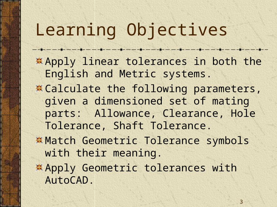
Learning Objectives
Apply linear tolerances in both the English and Metric systems.
Calculate the following parameters, given a dimensioned set of mating parts: Allowance, Clearance, Hole Tolerance, Shaft Tolerance.
Match Geometric Tolerance symbols with their meaning.
Apply Geometric tolerances with AutoCAD.
4
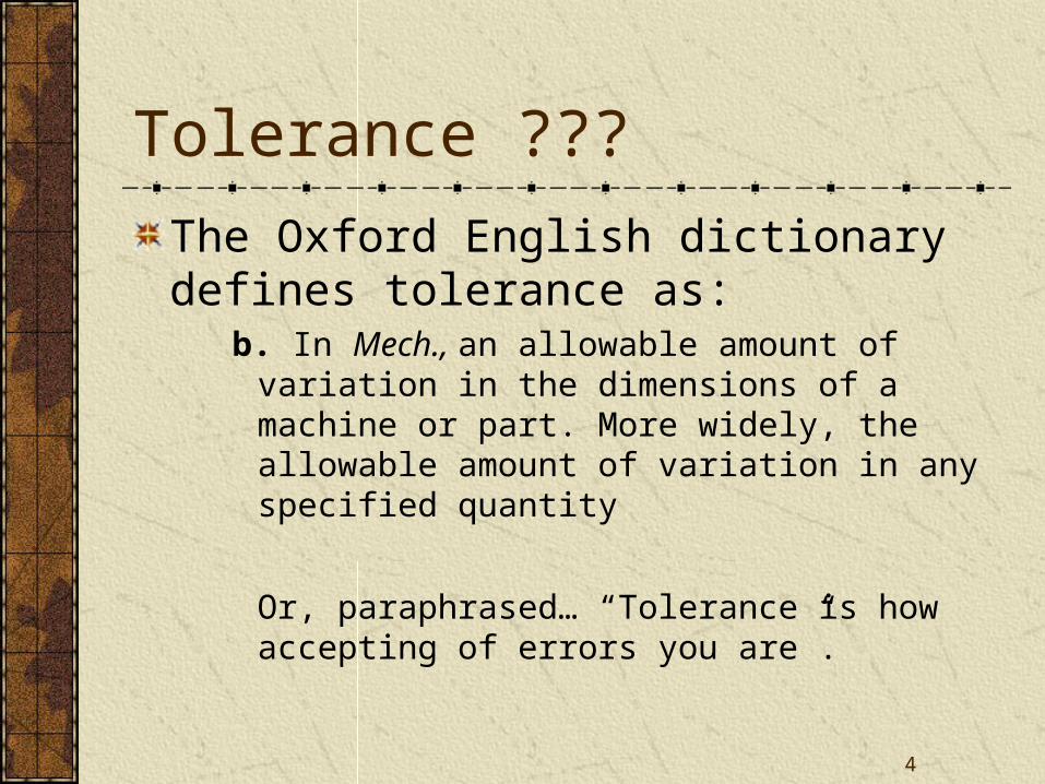
Tolerance ???
The Oxford English dictionary defines tolerance as:
b. In Mech., an allowable amount of variation in the dimensions of a machine or part. More widely, the allowable amount of variation in any specified quantity
Or, paraphrased… “Tolerance is how accepting of errors you are”.
5
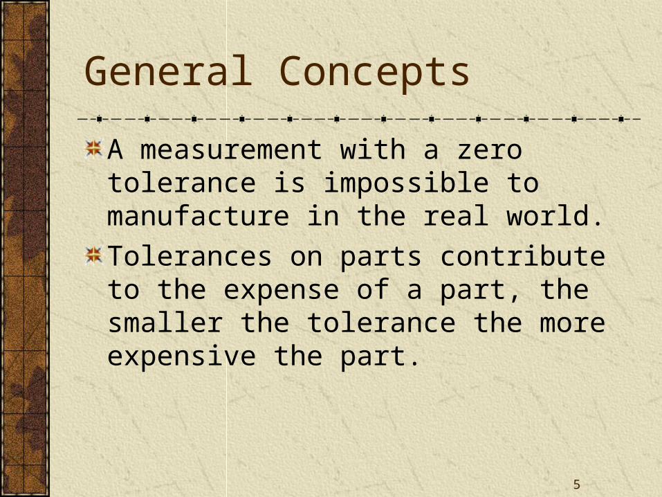
General Concepts
A measurement with a zero tolerance is impossible to manufacture in the real world.
Tolerances on parts contribute to the expense of a part, the smaller the tolerance the more expensive the part.
6
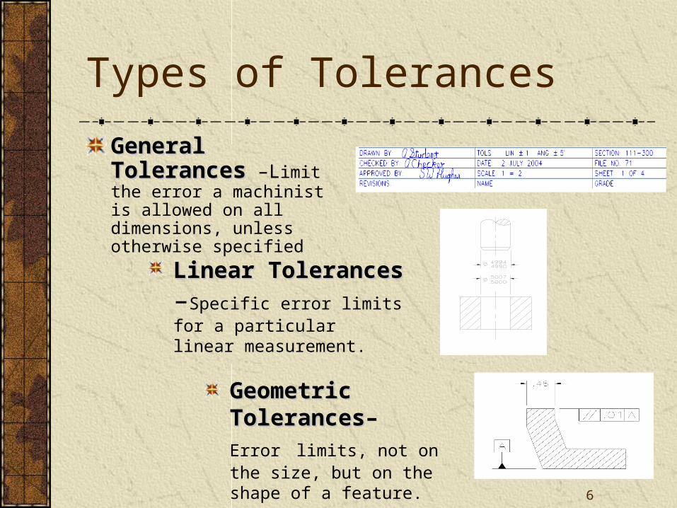
Types of Tolerances
General TolerancesGeneral Tolerances –Limit the error a machinist is allowed on all dimensions, unless otherwise specified
Linear TolerancesLinear Tolerances –Specific error limits for a particular linear measurement.
Geometric TolerancesGeometric Tolerances–
Error limits, not on the size, but on the shape of a feature.
7
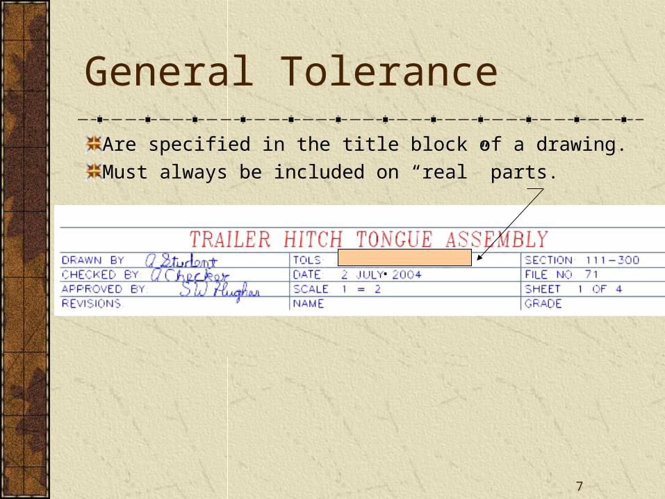
General Tolerance
Are specified in the title block of a drawing.
Must always be included on “real” parts.
.
8
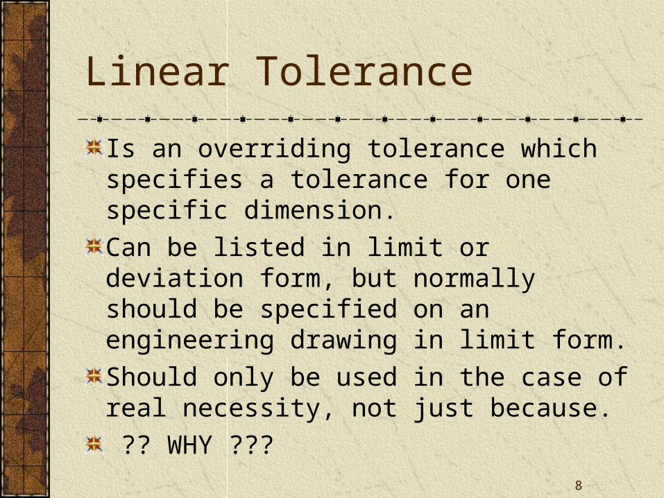
Linear Tolerance
Is an overriding tolerance which specifies a tolerance for one specific dimension.
Can be listed in limit or deviation form, but normally should be specified on an engineering drawing in limit form.
Should only be used in the case of real necessity, not just because.
?? WHY ???
9
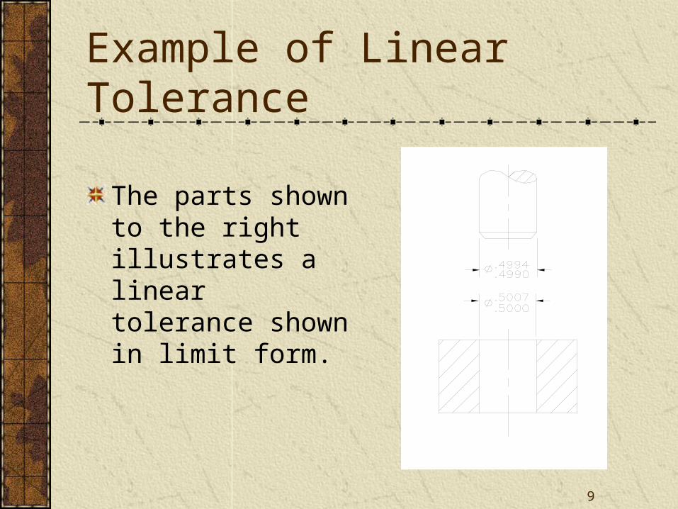
Example of Linear Tolerance
The parts shown to the right illustrates a linear tolerance shown in limit form.
10
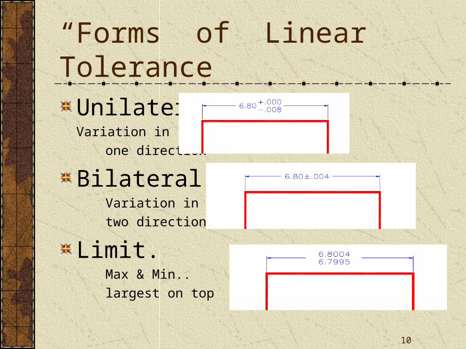
“Forms” of Linear Tolerance
Unilateral. Variation in
one direction
Bilateral. Variation in
two directions
Limit. Max & Min..
largest on top
11
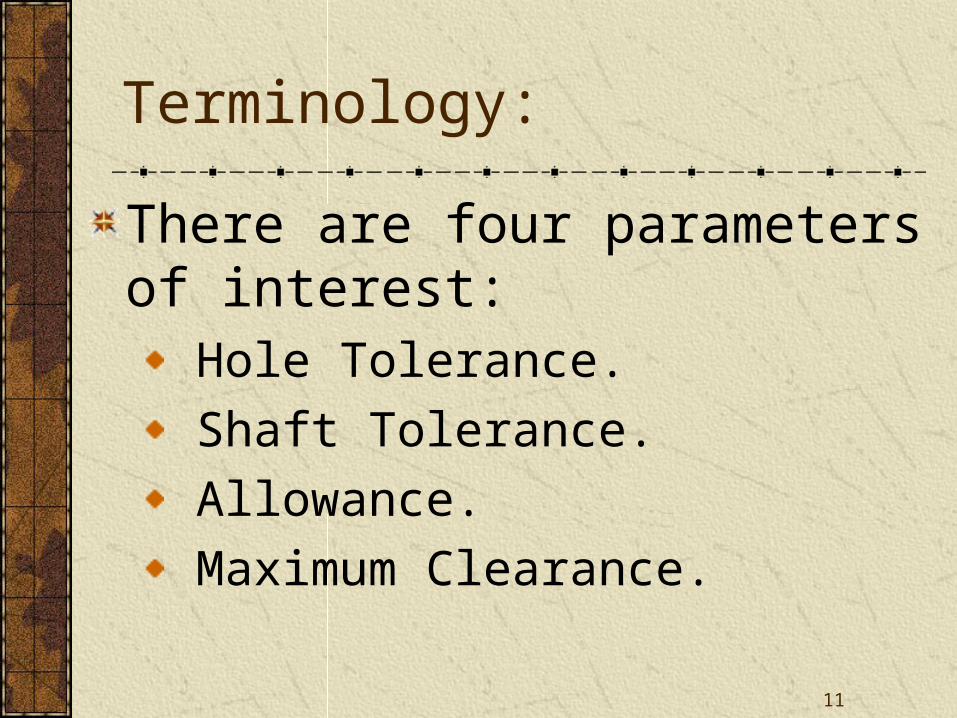
Terminology:
There are four parameters of interest: Hole Tolerance.
Shaft Tolerance.
Allowance.
Maximum Clearance.
12
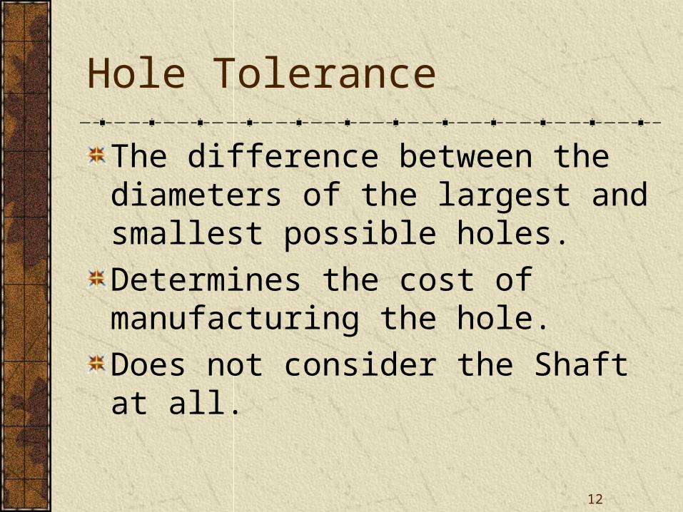
Hole Tolerance
The difference between the diameters of the largest and smallest possible holes.
Determines the cost of manufacturing the hole.
Does not consider the Shaft at all.
13
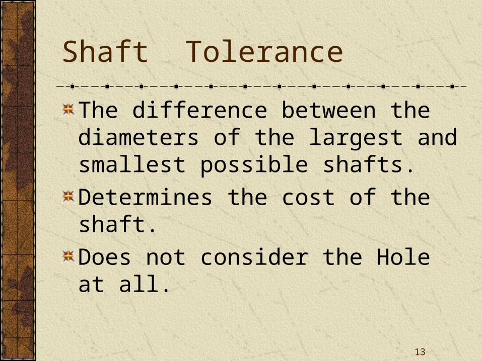
Shaft Tolerance
The difference between the diameters of the largest and smallest possible shafts.
Determines the cost of the shaft.
Does not consider the Hole at all.
14
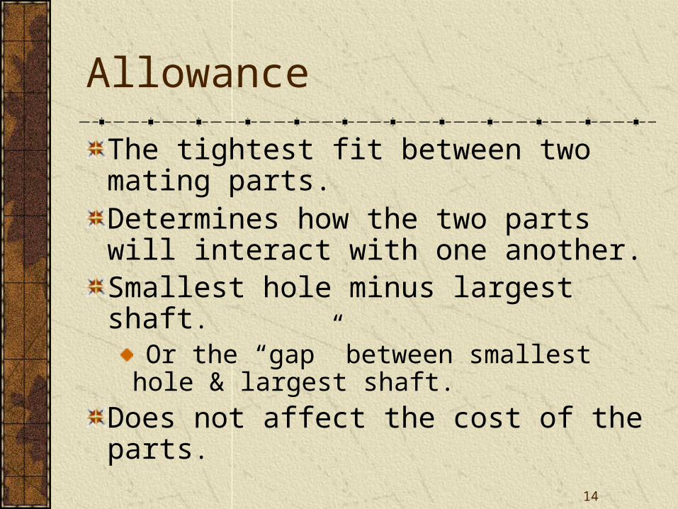
Allowance
The tightest fit between two mating parts.Determines how the two parts will interact with one another.Smallest hole minus largest shaft.
Or the “gap” between smallest hole & largest shaft.
Does not affect the cost of the parts.
15
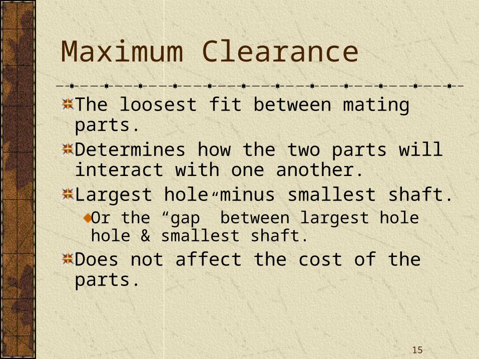
Maximum Clearance
The loosest fit between mating parts.Determines how the two parts will interact with one another.Largest hole minus smallest shaft.
Or the “gap” between largest hole hole & smallest shaft.
Does not affect the cost of the parts.
16
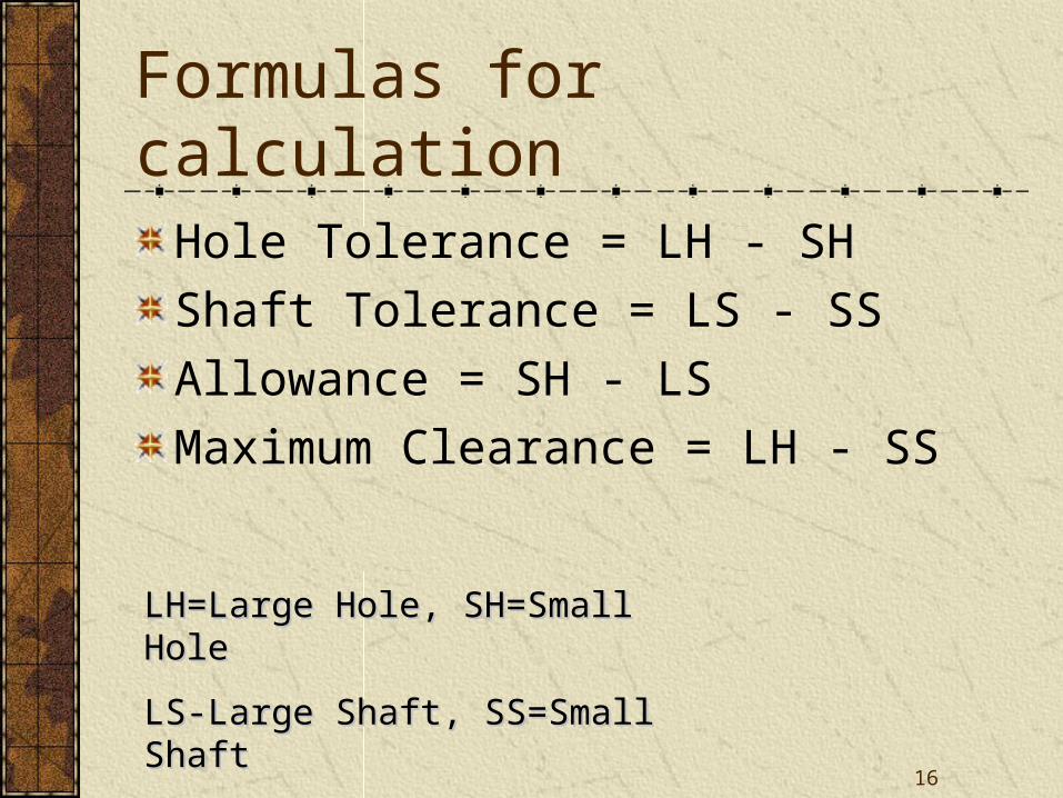
Formulas for calculation
Hole Tolerance = LH - SH
Shaft Tolerance = LS - SS
Allowance = SH - LS
Maximum Clearance = LH - SS
LH=Large Hole, SH=Small HoleLH=Large Hole, SH=Small Hole
LS-Large Shaft, SS=Small ShaftLS-Large Shaft, SS=Small Shaft
17
Other definitions
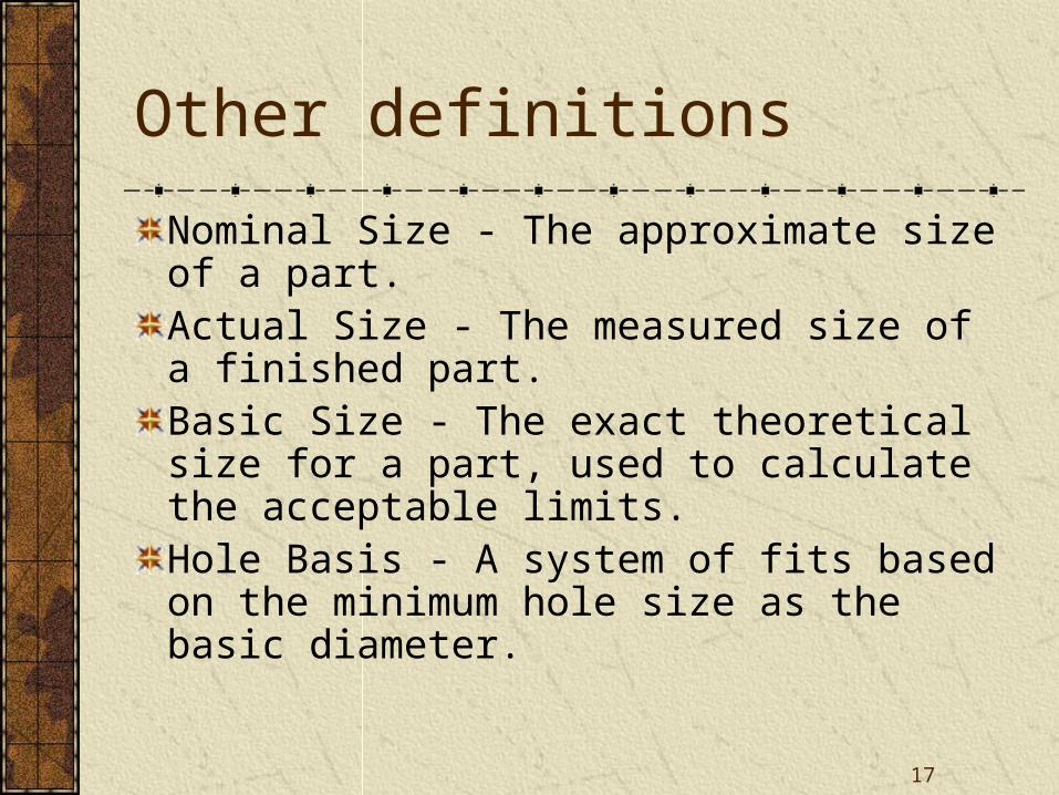
Nominal Size - The approximate size of a part.Actual Size - The measured size of a finished part.Basic Size - The exact theoretical size for a part, used to calculate the acceptable limits.Hole Basis - A system of fits based on the minimum hole size as the basic diameter.
18
Practical Application
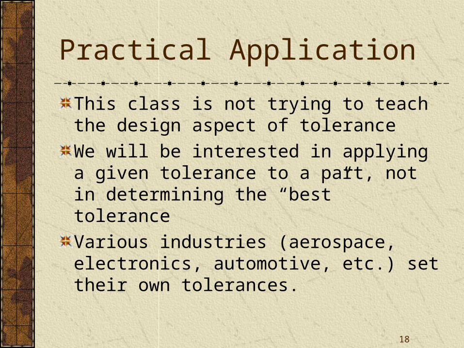
This class is not trying to teach the design aspect of tolerance
We will be interested in applying a given tolerance to a part, not in determining the “best” tolerance
Various industries (aerospace, electronics, automotive, etc.) set their own tolerances.
19
Types of Fits
Linear tolerances can be classified in 4 major categories, based on the interaction between the parts :
Clearance Fit.
Line Fit.
Transition Fit.
Interference Fit (Force Fit).
20
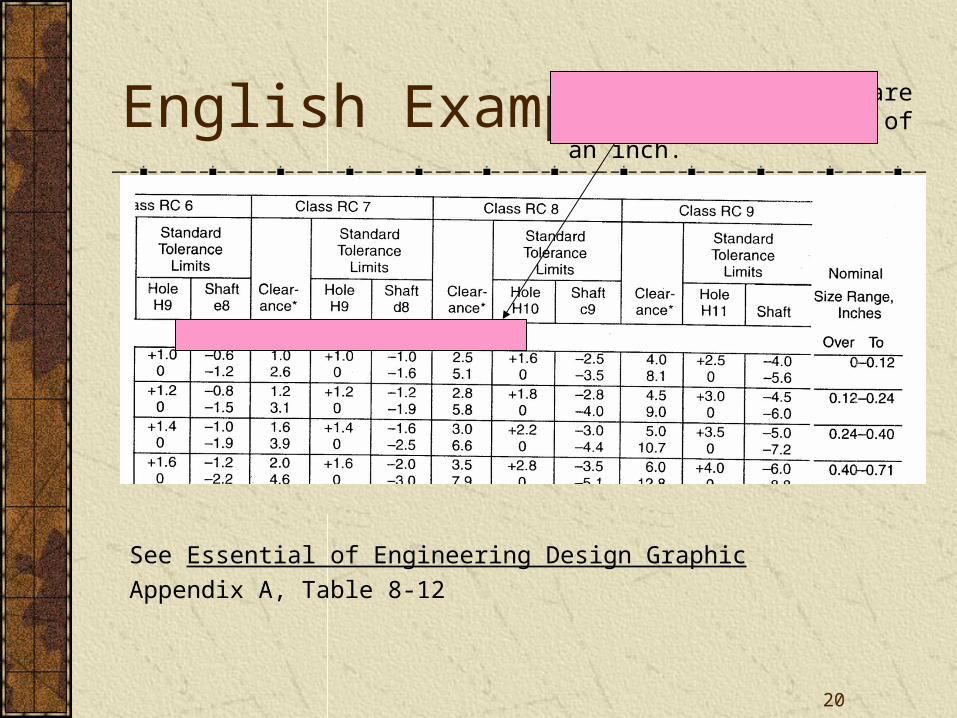
English Example Note that all values are listed in thousandths of an inch.
See Essential of Engineering Design Graphic
Appendix A, Table 8-12
21
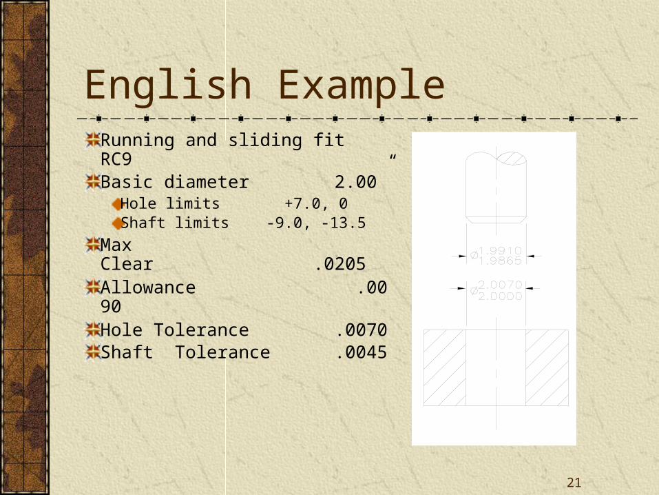
English ExampleRunning and sliding fit RC9Basic diameter 2.00”
Hole limits +7.0, 0Shaft limits -9.0, -13.5
Max Clear .0205Allowance .0090Hole Tolerance .0070Shaft Tolerance .0045
22
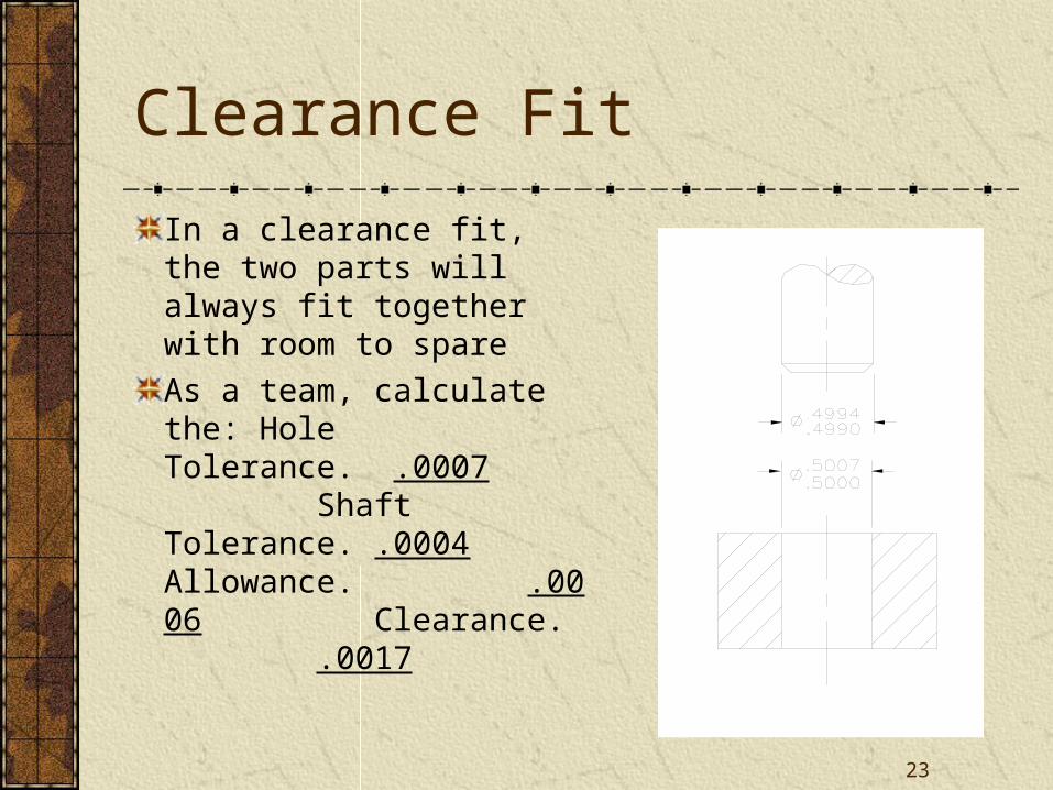
Clearance Fit
In a clearance fit, the two parts will always fit together with room to spare
23
Clearance Fit
In a clearance fit, the two parts will always fit together with room to spare
As a team, calculate the: Hole Tolerance. .0007 Shaft Tolerance. .0004 Allowance. .0006 Clearance. .0017
24
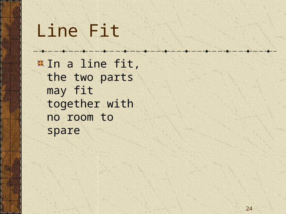
Line Fit
In a line fit, the two parts may fit together with no room to spare
25
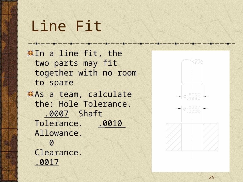
Line Fit
In a line fit, the two parts may fit together with no room to spare
As a team, calculate the: Hole Tolerance. .0007 Shaft Tolerance. .0010 Allowance. 0 Clearance. .0017
26
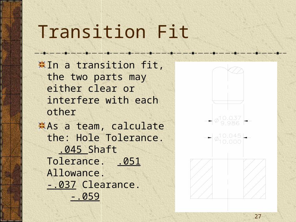
Transition Fit
In a transition fit, the two parts may either clear or interfere with each other…probably the cheapest way to manufacture products. Used with selective assembly process
27
Transition Fit
In a transition fit, the two parts may either clear or interfere with each other
As a team, calculate the: Hole Tolerance. .045 Shaft Tolerance. .051 Allowance. -.037 Clearance. -.059
28
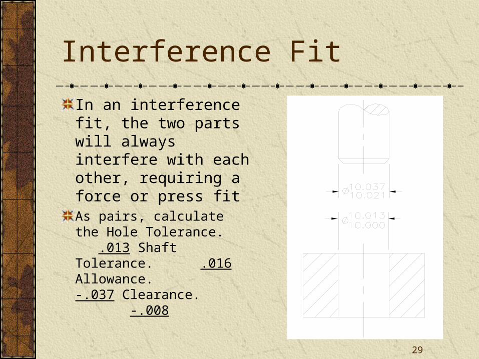
Interference Fit
In an interference fit, the two parts will always interfere with each other, requiring a force or press fit
29
Interference Fit
In an interference fit, the two parts will always interfere with each other, requiring a force or press fitAs pairs, calculate the Hole Tolerance. .013 Shaft Tolerance. .016 Allowance. -.037 Clearance. -.008
30
English Fits
ANSI standards list five type of fits:RC: Running and Sliding Clearance FitsLC: Clearance Locational FitsLT: Transition Locational FitsLN: Interference Locational FitsFN: Force and Shrink Fits
Each of these has several classes (Appendix A)The higher the class number, the greater the tolerance and the looser the fit.
31
Cle
aran
ce
Fits
Tra
nsiti
on
Inte
rfer
ence
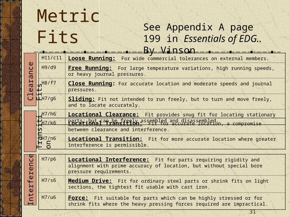
Metric FitsSee Appendix A page 199 in Essentials of EDG.. By Vinson
H11/c11 Loose Running: For wide commercial tolerances on external members.
H9/d9 Free Running: For large temperature variations, high running speeds, or heavy journal pressures.
H8/f7 Close Running: For accurate location and moderate speeds and journal pressures.
H7/g6 Sliding: Fit not intended to run freely, but to turn and move freely, and to locate accurately.
H7/h6 Locational Clearance: Fit provides snug fit for locating stationary parts; but can be freely assembled and disassembled.
H7/k6 Locational Transition: Fit for accurate location, a compromise between clearance and interference.
H7/n6 Locational Transition: Fit for more accurate location where greater interference is permissible.
H7/p6 Locational Interference: Fit for parts requiring rigidity and alignment with prime accuracy of location, but without special bore pressure requirements.
H7/s6 Medium Drive: Fit for ordinary steel parts or shrink fits on light sections, the tightest fit usable with cast iron.
H7/u6 Force: Fit suitable for parts which can be highly stressed or for shrink fits where the heavy pressing forces required are impractical.
32
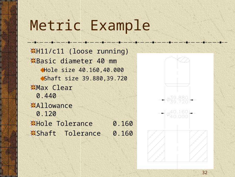
Metric Example
H11/c11 (loose running)
Basic diameter 40 mm Hole size 40.160,40.000
Shaft size 39.880,39.720
Max Clear 0.440
Allowance 0.120
Hole Tolerance 0.160
Shaft Tolerance 0.160