
TODD PACIFIC SHIPYARDS CORPORATION SEATTLE DIVISION ... · TODD PACIFIC SHIPYARDS CORPORATION...
331
TODD PACIFIC SHIPYARDS CORPORATION SEATTLE DIVISION P.O. BOX 3806 SEATTLE, WASHINGTON 98124 ALUMINUM WELDING OUT-OF-POSITION WELDING OF 5000 SERIES ALUMINUM ALLOYS USING PULSE GMAW POWER SOURCES FINAL REPORT JANUARY 1984 MIKE Y. NAKATA PRINCIPAL INVESTIGATOR
Transcript of TODD PACIFIC SHIPYARDS CORPORATION SEATTLE DIVISION ... · TODD PACIFIC SHIPYARDS CORPORATION...

TODD PACIFIC SHIPYARDS CORPORATIONSEATTLE DIVISIONP.O. BOX 3806
SEATTLE, WASHINGTON 98124
ALUMINUM WELDING
OUT-OF-POSITION WELDING OF 5000 SERIES ALUMINUMALLOYS USING PULSE GMAW POWER SOURCES
FINAL REPORTJANUARY 1984
MIKE Y. NAKATAPRINCIPAL INVESTIGATOR
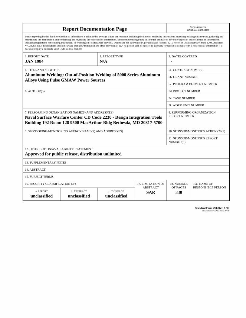
Report Documentation Page Form ApprovedOMB No. 0704-0188
Public reporting burden for the collection of information is estimated to average 1 hour per response, including the time for reviewing instructions, searching existing data sources, gathering andmaintaining the data needed, and completing and reviewing the collection of information. Send comments regarding this burden estimate or any other aspect of this collection of information,including suggestions for reducing this burden, to Washington Headquarters Services, Directorate for Information Operations and Reports, 1215 Jefferson Davis Highway, Suite 1204, ArlingtonVA 22202-4302. Respondents should be aware that notwithstanding any other provision of law, no person shall be subject to a penalty for failing to comply with a collection of information if itdoes not display a currently valid OMB control number.
1. REPORT DATE JAN 1984
2. REPORT TYPE N/A
3. DATES COVERED -
4. TITLE AND SUBTITLE Aluminum Welding: Out-of-Position Welding of 5000 Series AluminumAlloys Using Pulse GMAW Power Sources
5a. CONTRACT NUMBER
5b. GRANT NUMBER
5c. PROGRAM ELEMENT NUMBER
6. AUTHOR(S) 5d. PROJECT NUMBER
5e. TASK NUMBER
5f. WORK UNIT NUMBER
7. PERFORMING ORGANIZATION NAME(S) AND ADDRESS(ES) Naval Surface Warfare Center CD Code 2230 - Design Integration ToolsBuilding 192 Room 128 9500 MacArthur Bldg Bethesda, MD 20817-5700
8. PERFORMING ORGANIZATIONREPORT NUMBER
9. SPONSORING/MONITORING AGENCY NAME(S) AND ADDRESS(ES) 10. SPONSOR/MONITOR’S ACRONYM(S)
11. SPONSOR/MONITOR’S REPORT NUMBER(S)
12. DISTRIBUTION/AVAILABILITY STATEMENT Approved for public release, distribution unlimited
13. SUPPLEMENTARY NOTES
14. ABSTRACT
15. SUBJECT TERMS
16. SECURITY CLASSIFICATION OF: 17. LIMITATION OF ABSTRACT
SAR
18. NUMBEROF PAGES
330
19a. NAME OFRESPONSIBLE PERSON
a. REPORT unclassified
b. ABSTRACT unclassified
c. THIS PAGE unclassified
Standard Form 298 (Rev. 8-98) Prescribed by ANSI Std Z39-18

1.
2.
3.
4.
5.
6.
7.
8.
9.
10.11.
12.
13.
VOLUME I
TABLE OF CONTENTS— .
Foreword
Acknowledgements
Table of Contents
Introduction
Process Description
Pulse GMAW Power Sources & Accessories
Base Materials: 5000 Series Aluminum Alloy Sheet & Plates
Filler Materials: 5000 Series Aluminum Alloy Filler Wires
Weld Joint Designs
Shielding Gases & Weld Characteristics
Material Preparation
Weld Joint Fit-Up
Weld Tests

TODD PACIFIC SHIPYARDS CORPORATIONSEATTLE DIVISIONP.O. BOX 3806
SEATTLE, WASHINGTON 98124
ALUMINUM WELDING
OUT-OF-POSITION WELDING OF 5000 SERIES ALUMINUMALLOYS USING PULSE GMAW POWER SOURCES
FINAL REPORTJANUARY 1984
MIKE NAKATAPRINCIPAL INVESTIGATOR

This report (or manual) is submitted pursuant to a research and
development contract without any warranties, expressed or implied.
ANY POSSIBLE IMPLIED WARRANTIES OF MERCHANTABILITY AND/OR FITNESS
FOR PURPOSE ARE SPECIFICALLY DISCLAIMED.
i
FOREWARD
This report primarily describes the weld test work conducted during the
development of welding procedure qualification data, welding techniques
and welding procedure specification relative to full penetration, one-
side, out-of-position, manual pulsed gas metal arc butt welding of 5000
series aluminum alloy sheets and plates for marine fabrication.
This project was conducted with the use of
power sources (less than $5,000], feeders,
available to all U.S. Shipyards.
basic “off-the-shelf” welding
guns and accessories currently
Our literature survey indicated that substantial information covering gas
metal arc welding (GMAW) of aluminum alloy is available. However, very
little information appeared available on manual one-side, full weld
penetration gas metal arc butt welding of 5000 series aluminum alloy
sheets and plates in all welding positions with the use of either pulse
or short-arc welding modes on the pulse arc equipment. The short-circuit
mode has not been applied commonly to aluminum welding since it had origin-
ally been developed for steel in CO gases.2
No high speed oscilloscope nor high speed motion pictures were taken to
interpret the physical meaning of GMM in the pulse spray transfer or
IN the “pulsed short-circuiting” arc welding modes. All testing was
conducted on a one-on-one basis, i.e. the welder vs. attainment of full
penetration, one-side, out-of-position manual gas metal arc welding of
marine aluminum alloy sheet and plate.
It is anticipated that some of the results and techniques developed might
be implemented as an improved cost-effective approach to hull, superstruc-
ture, sheet metal and piping fabrication. It is also anticipated that
fabricators of surface effect ships, hydrofoils and crew boats may find
applications of some information developed.
ii
ACKNOWLEDGEMENTS
This welding project was initiated by the Society of Naval Architects
and Marine Engineers, Ship Production Committee; Technical Panel SP-7,
Welding and financed largely by government funds through a cost-sharing
contract between the U.S. Maritime Administration, Newport News Ship-
building and Drydock Company and Todd Pacific Shipyards Corporation,
Seattle Division.
Appreciation is expressed to the following:
Mr. R.W. SchaffranManagerShipbuilding Research ProgramU.S. Maritime AdministrationWashington, D.C.
Mr. M.I. TamerShip Production Committee Program ManagerNewport News Shipbuilding and Drydock CompanyNewport News, Virginia
Mr. B.C. HowserManager, Welding Engineering, and alsoSP-7 Panel ChairmanNewport News ShipbuildingNewport News, Virginia
Also, appreciation is expressed to the people in the Seattle Division of
Todd Pacific Shipyards Corporation particularly to:
Mr. C.R. Meurk, Executive Vice President
Mr. J.T. Gilbride, Jr., Vice President and General Manager
Mr. D.J. McDonnell, Assistant General Manager, Production
The author wishes to express his appreciation to Mr. J.C. Johnson,
Welding Engineer and Mr. Jonathan Hitch, Research and Development
welder for their technical and developmental welding portions of this
project. And also, to Mr. R. Bell, Quality Assurance and N.D.T. and
to Mrs. R. Turpen for preparation of the final report.
iii
SPECIAL ACKNOWLEDGEMENTS
Special acknowledgement is made to the following welding equipment manufac-
turers who provided their pulse gas metal arc equipment, accessories
and necessary technical support.
AIRCO WELDING PRODUCTS
Wayne E. Hoffman, General Manager Engineering
Niel. J. Normando; Manager, Technical Services and Application
Engineering
Carlos Galantino; Manager, Training and Technical Services
MALCOLM T. GILLILAND, INC.
Malcolm T. Gilliland, Owner
James Owen, Plant Manager
MILLER ELECTRIC MANUFACTURING COMPANY
R. Geissbuhler, vice President-Domestic Sales
M. Schiedermeyer; Project Engineer, Power Sources and Controls
K.L. Booher, Sales Manager-Domestic
G.N. Metco, Assistant Manager-Technical Sales
Monty Phillips, District Manager
iv

TABLE OF CONTENTS
1.
2.
3.
4.
5.
6.
7.
8.
9.
10.
11•
12.
1.3.
14.
15.
16.
17.
18.
19.
20,
21.
22.
Foreword
Acknowledgements
Table of Contents
Introduction
Process Description
Pulse GMAW Power Sources & Accessories
Base Materials: 5000 Series Aluminum Alloy Sheet & Plates
Filler Materials: 5000 Series Aluminum Alloy Filler Wires
Weld Joint Designs
Shielding Gases & Weld Characteristics
Material Preparation
Weld Joint Fit-Up
Weld Tests
chipping
Welding Techniques
Repair Welding
Preheat, Interpass, Post-Heat Temperatures
Mechanical Properties
Weld Machine Settings
Welding Procedure Specification: Guide
General Conclusions & Recommendations
References
v
INTRODUCTION
Substantial gas metal arc welding (GMAW) developmental work on aluminum
and aluminum alloys has been conducted by the Navy, Aluminum Manufactur-
ers, and the Shipbuilding Industry itself. However, very little work
has been conducted to develop out-of-position, full penetration, one-side,
manual gas metal arc butt welding of aluminum alloys with the use of
pulse spray or “pulse short-arc” modes. This phase of manual gas metal
arc welding of aluminum alloy sheet and plates has not been fully developed
nor fully utilized by the shipbuilding industry.
The pulse spray and also the short circuiting arc welding mode is a
variation of the gas metal arc welding process. The pulsed arc welding
power source usually provides a dual-level welding current and provides
substantially improved weld deposition control for out-of-position welding.
Both the background and the pulsed peak welding current can be controlled
separately or electronically so that the actual average welding current
is precise. In the past, out-of-position GMAW in the spray mode could
not be used effectively because the molten weld puddle was so
the puddle sagged or rolled because of gravity. With the use
pulsed GMAW power sources, however, the use of the background
hot that
of the new
level
provides sufficient cooling of the weld puddle to allow out-of-position
welding. Radiographic inspection quality levels were anticipated to be
superior to conventional GMAW welds, i.e. per MIL-STD-0900-003-9000;
“Radiographic Standards For Production and Repair Welds.”
1
The primary purpose of the project was to determine and establish manual
pulsed gas metal arc welding techniques and also welding machine settings
for the one-sided fusion welding of strain hardened 5000 series marine
aluminum alloy sheets and plates in the 1/16 inch to 1/2 inch thickness
range. The primary objective was to make manual butt welds in the horizon-
tal, vertical-up and overhead welding positions and produce full pene-
tration root weld pass deposits with the minimal use of strong backs
and without the use of either metallic or ceramic back-up bars. The
welding test piece parts to be welded were gas metal arc GMAW tack welded
only and were fiXtured with minimal restraints.
The primary objective of this project was to produce out-of-position, full
penetration, manual gas metal arc GMA. butt welds from one-side and yet
meet weld quality levels similar to those attained with the use of gas
tungsten arc welding GTAW. It was felt that substantial (30%-50%] cost
savings could be attained as a result of overall increased productivity
and minimum distortion weldments realized through out-of-position, one-
side, full penetration gas metal arc welding.
The advantages of pulsed spray welding were primarily higher deposition
rates when welding out-of-position. The other advantages are as follows:
Rework, repairs, or straightening costs would be minimized because full
penetration welds usually eliminate repairs on lack-of-fusion type
defects.
Weld quality levels similar to gas tungsten arc welding can be attained.
Weld distortion is held to a minimum because of low heat input and
good depth/width ratio weld cross sectional configuration.
Less weld repairs will be encountered.
Easier and greater working ranges for out-of-position welding will be
appreciated.
However, in spite of the many
provides, many welding people
1] higher cost of the welding
advantages that
have avoided it
machines/system
in setting the machine up to the proper pulse
voltage balance in addition to taking care of
variables.
2
the pulse arc process
because of two major factors;
and; 2) the complexity
voltage peak vs. background
the other necessary machine
Also, in the past many welders and welding engineers have shied away
from using the conventional GMAW short-circuiting arc process when welding
aluminum alloy sheet/plate materials in the out-of-position mode. This
was because the droplet transfers were uncontrollable due to improper
balance of slope, inductance, electromagnetic pinch force, pulse amplitude,
pulse duration, pulse frequency and voltage feedback control systems.
It is anticipated that the results of this report may encourage aluminum
and aluminum alloy fabricators to consider the advantages of manual pulsed
arc welding of aluminum and aluminum alloy sheet and plate materials by
utilizing the out-of-position, full penetration, one-side welding technique.
For clarity’s sake, various discussions, comments and often conclusions
and recommendations follow a specific topic because of the numerous welding
variables involved in this study.
3
PROCESS DESCRIPTION
In order to define pulsed arc welding, it appears necessary to define gas
metal arc welding GMAW which is more commonly known as MIG welding or
metal inert gas welding.
GAS METAL ARC WELDING: GMAW
The American Welding Society (AWS) defines gas metal arc welding GMAW
as follows:
“An arc welding process wherein coalescence is produced by heating
with an arc between a continuous filler metal (consumable) electrode
and the work. Shielding is obtained from an externally supplied gas."
The basic GMAW system usually consists of a power source, wire feeder with
controls, welding gun (torch) and shielding gas system and accessories.
See Figure 1.
The standard (non-pulsedl gas metal arc welding of aluminum alloys in the
spray transfer mode is used primarily for welding plate materials (.188
inch thick and greater) and sheet materials (.125 inch thick and greater).
When the conventional spray transfer mode is used the welding is usually
done in the flat position. This is because the higher current levels
make the weld puddle very fluid. In the GMAW spray transfer mode the fine
metal droplets are pinched off the wire and and propelled across the arc
gap to the work as illustrated in Figure 2.
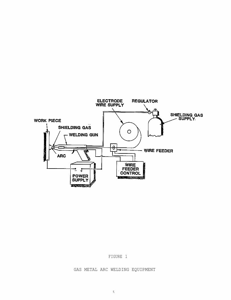
FIGURE 1
GAS METAL ARC WELDING EQUIPMENT
5
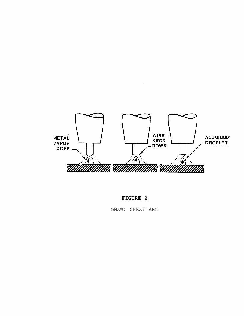
FIGURE 2
GMAW: SPRAY ARC
PULSED GAS METAL ARC WELDING
Pulsed arc welding is a variation of the gas metal arc welding GMAW
process. With pulsed GMAW, the welding power source(s) provides a dual
level welding current and provides substantiaily improved weld deposi-
tion control especially for out-of-position welding applications. Both
the background and the pulsed peak welding currents can be controlled
separately so that the actual average welding current may be set more
precisely than with the use of conventional GMAW power sources.
In pulsed spray gas metal arc welding the current is varied between a
high (peak) and low (background) value. The low level of current isbelow the non-pulsing transition current while the high on the peak
current level is well into the spray arc region, i.e. if the upper current
were continuous, it would provide spray transfer and if the lower current
were continuous it would produce globular transfer. Metal is transferred
to the work during the peak current levels. Figure 3 illustrates the
pulsed GMAW welding current cycle pattern. In the spring of 1983, most
of the "off-the-shelf” pulsed arc power sources manufactured in the United
states appeared to use pulse in either 60 or 120 pulses per second.
However, one manufacturer has recently begun manufacturing a pulse GMAw
power source covering an approximate range of 50-250 pulses per second.
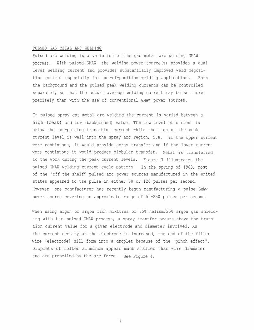
When using argon or argon rich mixtures or 75% helium/25% argon gas shield-
ing with the pulsed GMAW process, a spray transfer occurs above the transi-
tion current value for a given electrode and diameter involved. As
the current density at the electrode is increased, the end of the filler
wire (electrode] will form into a droplet because of the "pinch effect".
Droplets of molten aluminum appear much smaller than wire diameter
and are propelled by the arc force. See Figure 4.
7
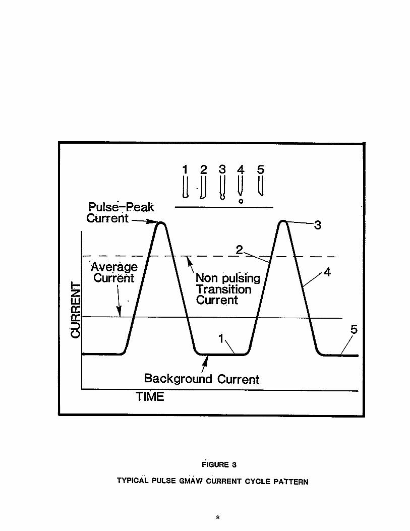
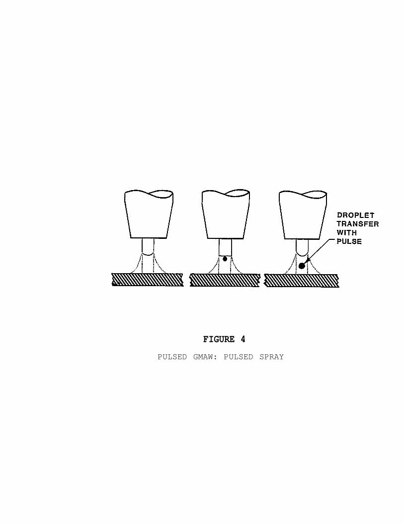
FIGURE 4
PULSED GMAW: PULSED SPRAY
The three methods of metal transfer in pulsed gas metal arc welding are
pulsed spray, globular and short-circuiting transfer.
PULSED SPRAY TRANSFER
As discussed earlier in the text, the pulsed arc GMAW process utilizes
a peak and background current levels producing an average current value.
The resultant current level is a lower average current heat level than
when a continuous conventional spray transfer mode is used. The tip of
the filler wire melts and the molten metal drops transfer in a spray during
each current peak pulse when most of the energy input as utilized for
melting the base material and the filler wire material. Usually, there is
not sufficient time for globular transfer to occur and more than adequate
time at temperature for spray transfer to melt the electrode. Adjustment
of both the pulse peak and amperage and background is usually available
unless these functions are electronically pre-programmed. The arc is
maintained by the background current. The pulse peak current must be
set high enough so that the metal droplets are propelled through the
arc at a high velocity for one-side, full penetration, manual pulsed
gas metal arc welding in the out-of-position mode.
The droplet size tends to stay the same but the rate of drops transferred
increases with frequency, i.e. from 50-250 pulses per second (pps).
Most power sources pulse only in 60 or 120 pps. The cooler arc is attained
by using the lower pulse, i.e. 50 pps or 60 pps depending on the power
source.
With the use of the conventional continuous (standard GMAW) spray arc,
it was difficult for the average "new hire welders to make out-of-position
welds. The work usually had to be positioned for down hand (flat) welding.
On the other hand, with the use of the pulse current a lower heat input
spray arc transfer may be used for welding in the vertical-up, horizontal
and overhead welding positions.
The pulsed gas metal arc process permits the use of larger diameter wires
with the use of push wire feeders. A much lower average current may be
10
used with 3/64 inch diameter wires than is possible for the conventional
GMAW process. Larger diameter filler wires generally provide better wire
feeding capabilities in addition to better weld deposit quality, i.e.
.030 inch diameter filler wires have lower columnar strength and requires
a pull gun.
GLOBULAR ARC TRANSFER
When pulsed gas metal arc welding power sources are used, the globular
arc transfer usually occurs below the pulse peak current corresponding
to the conventional non-pulsing transition current level. This globular
transfer range covers the minimum current density which will melt the
filler wire up to the point where higher peak amperage produces a pulsed
spray transfer.
With the use of conventional gas metal arc welding power sources, the
globular transfer usually is avoided because the arc cone covers a much
larger area and causes shallow
irregular metal deposition and
position welding.
weld penetration, lack of fusion, and
certainly is not suitable for out-of-
“PULSED SHORT-CIRCUITING ARC"
As described in the previous paragraphs, the conventional globular arc
transfer does not lend itself to one-side, out-of-position full penetra-
tion manual gas metal arc welding. See Figure 5. The Airco PA-350
power source in the “short-circuiting mode” does not appear to be the
same as the conventional short-arc mode. When the globules short-circuit
by coming in contact with the puddle and electrode at the same time the
arc force is so strong that the molten globules have good arc stability
and provide good full penetration welds with good depth to width ratio.
Unfortunately, no high speed motion pictures at 3,000 frames per second
were taken and also the use of a high speed oscilloscope was not available.
11
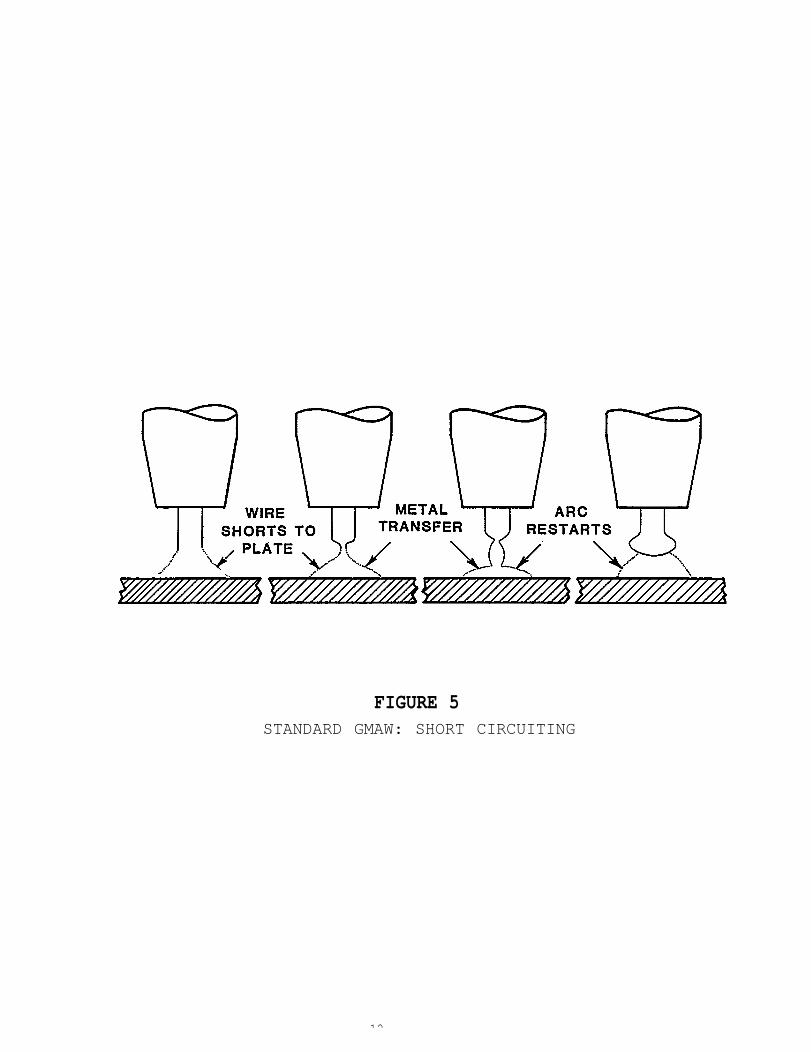
FIGURE 5STANDARD GMAW: SHORT CIRCUITING
12
The advantages of the pulse and “pulse short-circuiting” modes of gas
metal arc welding are as follows:
Permits the welder to make a one-side, full penetration, out-of-position weld using the manual GMAW process.
Provides cooler arc and less distortion.
Minimizes weld spatter and undercutting.
Permits the out-of-position welding of thin sheet materials, e.g..063 inch thicknesses of aluminum alloy sheet.
Permits spray transfer welding at average currents below those normallypossible.
Provides improved arc control for out-of-position welding and moreeffective welding of thin gauge material, with all the advantagesof spray transfer, i.e. minimizes excessive weld puddle fluidity.
Permits use of larger diameter electrode wires which cost less, feedeasier and also have a lower surface-to-volume ratio which reducesthe possibility of weld porosity and, in some cases, weld cracking.
Provides precision control of current to assure bead shape and rootpenetration approaching GTAW quality.
13
PULSED ARC GMAW POWER SOURCES
When this project was originally proposed in the Spring of 1982, only
one production model “off-the-shelf type” pulsed GMAW power source appeared
to be available in the United States. This was the Airco PA-3A. Since
that point in time, however, American manufacturers have begun producing
pulsed GMAW power sources, primarily because of the interest in utilizing
the advantages offered by low heat input for joining quench and tempered
steels such as HY-80/HY-100 for submarine and other marine applications.
The original scope of this program stipulated the determination of the
“best" pulsed GMAW power source for welding aluminum. However, during
the course of this program it was determined that the preferred power
source should be left as a choice of individual shipyard Welding Engineers
for their particular application. As this program progressed, it became
more evident that the establishment of the “best" power source would be
extremely subjective and difficult. It would result in the unfair compar-
ison of dissimilar GMAW power sources, and wire feeder systems, i.e. not
suitable for comparison.
ers are working on their
The welding power source
Furthermore, many of the equipment manufactur-
next generation pulse power sources.
designed for pulsed gas metal arc welding is
usually a constant voltage type. Pulsed GMAW power sources usually have
added pulse features which significantly improve arc stability, weld puddle
control, weld arc column shape, and also provide a wider and controllable
spray arc transfer working range.
The program covered four types of pulsed arc welding power sources. These
are as follows:
1. Airco PA-3A
2.Airco PA-350
3. Gilliland CV 600 FI-PA
4. Miller Pulstar
14
Each pulsed GMAW power source has its own special merits and areas of appli-
cations. They all appeared to operate according to the same basic principles
of a GMAW power source. However, substantial variations in welding power
source specifications appear in areas such as process modes, pulse rates
(pulse per second), pulse source(s), and pulse control method, etc.
During the welder familiarization period with the four candidate pulse
arc welding power sources, it was surprising to discover that the short-
circuiting arc mode needed to be included as another alternative approach
to attain our primary program objective, i.e. full weld penetration from
one-side, out-of-position manual GMNT. As described in the previous
paragraph under Process Description, the “new” short arc mode does not
appear to be the conventional short-circuiting arc transfer with which
most of us are familiar.
The four pulse GMAW power sources are described in the following paragraphs.
* * * * * * *
15
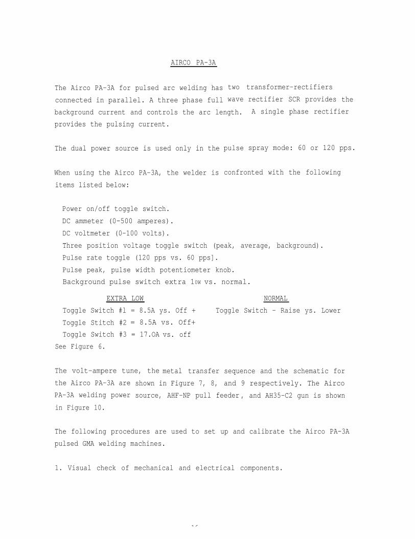
AIRCO PA-3A
The Airco PA-3A for pulsed arc welding has
connected in parallel. A three phase full
two transformer-rectifiers
rectifier SCR provides thewave
background current and controls the arc length. A single phase rectifier
spray mode: 60 or 120 pps.
provides the pulsing current.
The dual power source is used only in the pulse
When using the Airco PA-3A, the welder is
items listed below:
confronted with the following
Power on/off toggle switch.
DC ammeter (0-500 amperes).
DC voltmeter (0-100 volts).
Three position voltage toggle switch (peak, average, background).
Pulse rate toggle (120 pps vs. 60 pps].
Pulse peak, pulse width potentiometer knob.
Background pulse switch extra 10W vs. normal.
EXTRA LOW NORMAL
Toggle Switch #l = 8.5A ys. Off + Toggle Switch - Raise ys. Lower
Toggle Stitch #2 = 8.5A vs. Off+
Toggle Switch #3 = 17.OA
See Figure 6.
vs. off
metal transferThe volt-ampere tune, the sequence and the schematic for
and 9 respectively. The Aircothe Airco PA-3A are
PA-3A welding power
in Figure 10.
shown in Figure 7, 8,
source, AHF-NP pull feeder , and AH35-C2 gun is shown
The following procedures are used to set up and calibrate the Airco PA-3A
pulsed GMA welding machines.
1. Visual check of mechanical and electrical components.
16

2.
3.
4.
5.
6.
7.
8.
9.
Hook up primary power and check main contactor for proper operation.
Check voltages on transformer secondaries for proper output.
Check phasing on transformer secondaries.
Calibrate firing circuit printed circuit board for minimum and maximumpulsed width.
Check background voltage.
Check meter accuracy against
Load test output for maximum
oscilloscope.
voltage - amperage.
Set up with wire feeder and weld test.
NOTE :
The above check list is reduced to items 2, 6 and 9 only in order for
a user to set-up.
17
AIRCO PULSE ARC 350WELDING SYSTEM
The Airco PA-350 Welding System consists of
welding power source, System 1 wire feeder,
control pendant.
The lightweight feeder is a dual drive roll
a constant voltage solid state
Aircomatic GMAW gun and remote
unit, double insulated and
totally enclosed for added operator and component protection. All wire
feeder control circuitry is housed in the power source environmental
compartment.
Standard features include slow run-in start, wire jog switch, built-in
three-roll wire straightener, calibrated adjustable drive roll pressure
and fixed pre- and post-flow timers. Wire speed is automatically controlled
over a range of 40-800 inches per minute (i.p.m.) with standard hard and
soft wire sizes .035 through l/16 inch
The
arc
*
The
remote control pendant contains the synergic control potentiometer,
length fine adjustment potentiometer, a manual wire feed speed adjust-
potentiometer and a manual/automatic mode switch.
welding gun included with the system is a new Aircomatic air-cooled
gun. It is rated at 400 amps. C02 and is of single conduit design with
heavy duty slip-on nozzle and quick disconnect fitting.
The welding meters and controls of the Airco PA-350 power source are listed
as follows:
- DC ammeter CO-500 amperes).
- DC voltmeter CO-50 volts).
- Pulse process toggle
- Crater toggle switch
switch (Up = C02)
(down = Argon/C0 2), and (middle= Pulse Mode).
(up = pulse
(down - Argon/C0 2).
23
- Push buttons #1 #2 #3 #4CRATER WIREFILL DIAMETER MATERIAL GAS
in = on in - .O35° in = SS in = purge
out = off out = .045” out - Ms out = weld
NOTE :
SS = Stainless SteelMS = Mild Steel
- Crater current potentiometer. (applies only when #1 is pushed in).
Crater current (0-10)
Crater voltage (0-10]
Background (0-10)
- Power on/off switch.
Important features of this welding system are as follows:
“Electronic” wave shaping circuit in the C02 or Argon/C02 mode.
Pulsed spray and dip transfer process capabilities.
Single knob synergic control.
Crater fill.
Pre/post flow timers.
Solid state contactor.
Line voltage compensation.
Thermal overload protection and indicator light.
Environmentally protected cabinet design.
400 amp. gun (1O ft.).
Remote control pendant.
Voltmeter and ammeter.
115 VAC auxiliary powerdual receptacle.
Energy saving circuit.
Wire feeder:
- lightweight, totally
with 5 amp. circuit breaker fuse (0.5 kva) and
enclosed.
- wire sizes: .035 and .045 inch hard standard and 3/64 and 1/16inch soft, optional 12 and 14 inch spools standard and 8 inch and60 lbs. chipboard cores optional.
Slow run-in.
Wire job
Built-in
Wire tip
switch.
wire straightener.
conditioning (stub burn off).
24

The Pulse Arc 350 system is a multi-purpose unit designed for pulsed spray
transfer/"pulsed short-circuiting arc” welding.
Single control knob automatically establishes average current (wire feed
speed) and average arc voltage for an optimum welding condition based on
a given material, tire diameter and shielding gas. This system eliminates
the need to individually set peak voltage/current, pulse frequency and
background voltage current. The synergic characteristic of this control
makes these selections automatically. The system consists of a power
source, a totally-enclosed wire feeder, remote control pendant
lightweight 400 amp. GMAW gun.
The power source output is controlled by a
transistors
tions.
This system
which also compensate for line
allows out-of-position welding
solid state control
power input voltage
with aluminum wires
and a
and power
fluctua-
and is
ideally suited for thin gauge material allowing increased welding rates
without an increase in heat input resulting in subsequent weldment wax-
page. In addition, excellent “pulse short-circuiting” welding maybe
performed at outputs as low as 40 amperes, i.e. 3/64 inch diameter wire.
The standard system comes equipped to weld with .035 and .045 inch mild
steel and stainless steel wires. With appropriate option, the system can
weld with aluminum in 3/64 inch and 1/16 inch diameter wires.
The PA-350/System 1 feeder allows the use of one-to-two 1-2) size larger
diameter electrodes. For example, 3/64 inch diameter aluminum alloy filler
wires can be used in lieu of .035 inch or .030 inch diameters when welding
a specific base material thickness such as .063 inch material thickness.
This feature alone improves productivity because the use of larger diame-
ter wire improves weld quality, offers better wire feeding characteristics
and also reduces equipment down time.
The Airco PA-350 Welding System specification covering the power source,
wire feeder, gun and physical data is illustrated in Figure 11. Also,
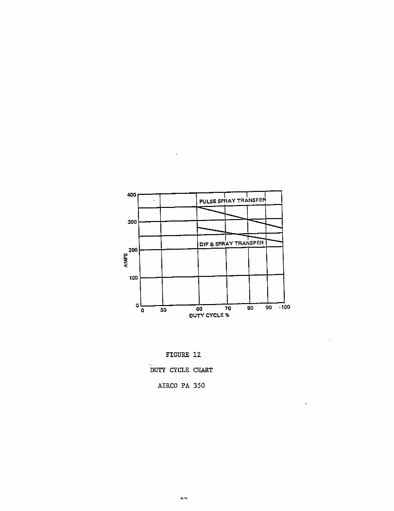
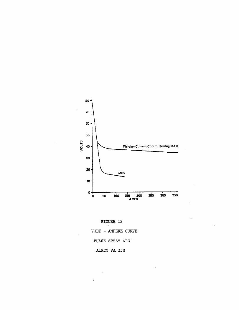
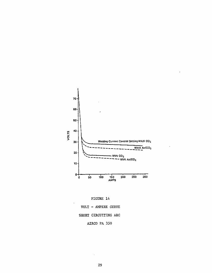
a duty cycle chart, volt-ampere curve for pulsed spray arc, volt-ampere
curve for short-circuiting mode and block diagram are illustrated in Figures
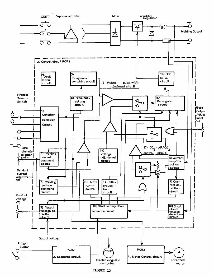
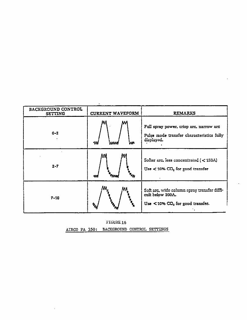
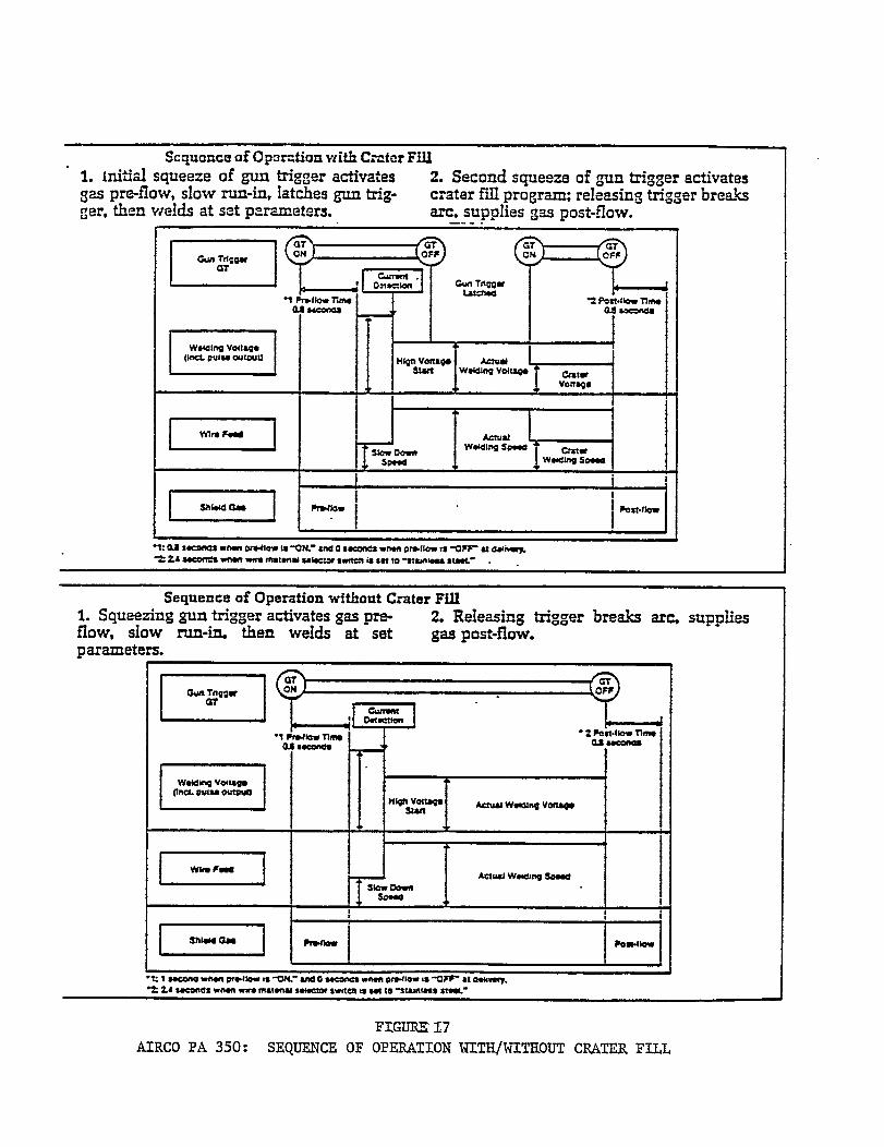
12, 13, 14, and 15. Also, background control settings and sequence of
operations with and without crater fill are shown in Figures 16 and 17.25
.
POWER SOURCE PULSE SPRAY PROCESS DIP-TRANSFER PROCESS
Rated Output 350 Amps @ 36 Volts 280 Amps @ 27.5 VoltsDuty Cycle 60% 60%Primary Input 3 Phase 3 Phasevolts 230/460,60 HZ 230/460,60 HzPrimary Input Amperes 50/25 40/20KW-Input 18 14.4KVA-Input 20 16Maximum Open Circuit Volts 78 78Auxiliary Power (KVA) 0.5 @ 115 VAC 0.5 @ 115 VAC
WIRE FEEDER
Feed Type PushWire Sizes:
Hard 0.035 inch (0.889 mm) Standard0.045 inch (1.14 mm) Standard
soft 3/64 inch (1.19 mm)1/16 inch (1.58 mm)
Feed Rate 40 to 800 ipm (1.02 to 20.5 mpm)Spool Size 12 and 14 inch standard
8 inch and 60 lb. Chipboard cores optionalGUN
Cooling AirGooseneck Angle 45°Rated 60% Duty Cycle
(DCRP) Amps: C02 400Argon 360
Conduit Length 10 feet (3.04 m)PHYSICAL
Net Weight System 420 lbs. (189 kg)Shipping Weight System 445 lbs. (201 kg)Height (Power Source) 27-1/4 inches (69 cm)Width (Power Source) 19-1/4 inches (49 cm)Depth (Power Source) 39 inches (99 cm)Height (Wire Feeder) 12-1/2 inches (32 cm)Width (Wire Feeder) 8 inches (20 cm)Depth (Wire Feeder) 19 inches (48 cm)
DESCRIPTION
Pulse Arc 350 Power Source/Feeder/Gun/Remote Control Pendant230/460, 3 phase, 60 Hz
FIGURE 11
AIRCO PA-350 WELDING SYSTEMSPECIFICATION
26
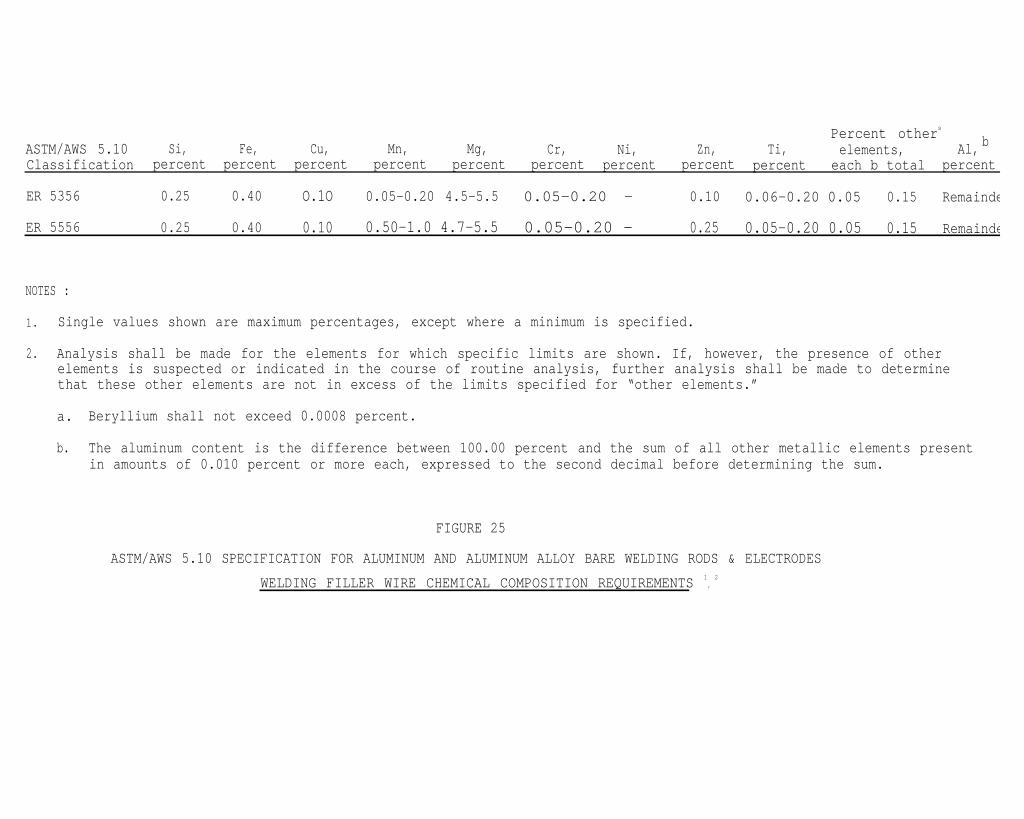
Percent others
ASTM/AWS 5.10 Si, Fe, Cu, Mn, Mg, Cr, Ni, Zn, Ti, b
Classificationelements, Al,
percent percent percent percent percent percent percent percent percent each b total percent
ER 5356 0.25 0.40 O.1O 0.05-0.20 4.5-5.5 0.05-0.20 - 0.10 0.06-0.20 0.05 0.15 Remainde
ER 5556 0.25 0.40 0.10 0.50-1.0 4.7-5.5 0.05-0.20 - 0.25 0.05-0.20 0.05 0.15 Remainde
NOTES :
1. Single values shown are maximum percentages, except where a minimum is specified.
2. Analysis shall be made for the elements for which specific limits are shown. If, however, the presence of otherelements is suspected or indicated in the course of routine analysis, further analysis shall be made to determinethat these other elements are not in excess of the limits specified for “other elements.”
a. Beryllium shall not exceed 0.0008 percent.
b. The aluminum content is the difference between 100.00 percent and the sum of all other metallic elements presentin amounts of 0.010 percent or more each, expressed to the second decimal before determining the sum.
FIGURE 25
ASTM/AWS 5.10 SPECIFICATION FOR ALUMINUM AND ALUMINUM ALLOY BARE WELDING RODS & ELECTRODES
WELDING FILLER WIRE CHEMICAL COMPOSITION REQUIREMENTS 1
’
2
Welder acceptance of the Airco PA-350 prompted the following comments:
- Substantial reduction in spatter.
- Excellent weld cleaning action.
Pulsed frequency that is optimum for the welding current is automaticallyprogrammed, e.g. at 150 amperes approximately 150 pulses per second(PPS).
- The “pulsed short-circuit” frequency does not vary in extreme, i.e.consistent small droplet arc transfers.
- The “pulsed short-circuiting” arc has consistent short-arc lengths2-3 times wire diameters.
- The welding arc is stable because a closed loop electronic feed-backsystem apparently is constantly monitoring the welding current/voltageand controlling it consistently and reliably to enable small moltendroplets to transfer from the wire tip to the weld puddle.
- The Binzel torch is a wire push type gun. It is light and air cooledand eliminates operator fatigue when compared with the much heavierAirco water cooled AH 35-C2 pull gun.
- A simple integrated single dial sets the welding condition requested.A remote pendant controls and adjusts the pulse frequency, pulse width,background voltage and peakvoltage automatically. Heat input isregulated by the current-control potentiometer on the remote pendant.
- The stable pulsed spray arc and the “pulsed short-circuiting” arc modeoffers out-of-position, one-side, full penetration welds from .063inch through .125 inch thicknesses in 5000 series aluminum alloys.
* * * * * * *
The original plan was to use the Airco PA-3A power source to generate our
benchmark (base line) information relative to welding techniques and
test data. However, during the course of this project, the Airco PA-3A
malfunctioned and while this unit was being repaired we discovered the
unusual "pulsed short-circuiting’r mode on the Airco PA-350. At this
point in time, the Airco PA-350 power source, System 1 wire feeder, and
Aircomatic 400 ampere torch was substituted to determine and establish
the basic objectives of this project.
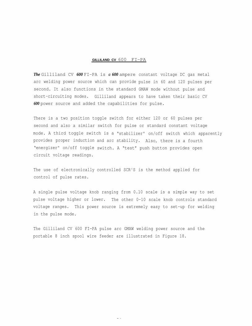
GILLILAND CV 600 FI-PA
The Gilliland CV 600 FI-PA is a 600 ampere
arc welding power source which can provide
second. It also functions in the standard
short-circuiting modes. Gilliland appears
constant voltage DC gas metal
pulse in 60 and 120 pulses per
GMAW mode without pulse and
to have taken their basic CV
600 power source and added the capabilities for pulse.
There is a two position toggle switch for either 120 or 60 pulses per
second and also a similar switch for pulse or standard constant voltage
mode. A third toggle switch is a “stabilizer" on/off switch which apparently
provides proper induction
“energizer" on/off toggle
circuit voltage readings.
The use of electronically
control of pulse rates.
and arc stability. Also, there is a fourth
switch. A “test” push button provides open
controlled SCR'S is the method applied for
A single pulse voltage knob ranging from 0.10 scale is a simple way to set
pulse voltage higher or lower. The other 0-10 scale knob controls standard
voltage ranges. This power source is extremely easy to set-up for welding
in the pulse mode.
The Gilliland CV 600 FI-PA pulse arc GMAW welding power source and the
portable 8 inch spool wire feeder are illustrated in Figure 18.
34
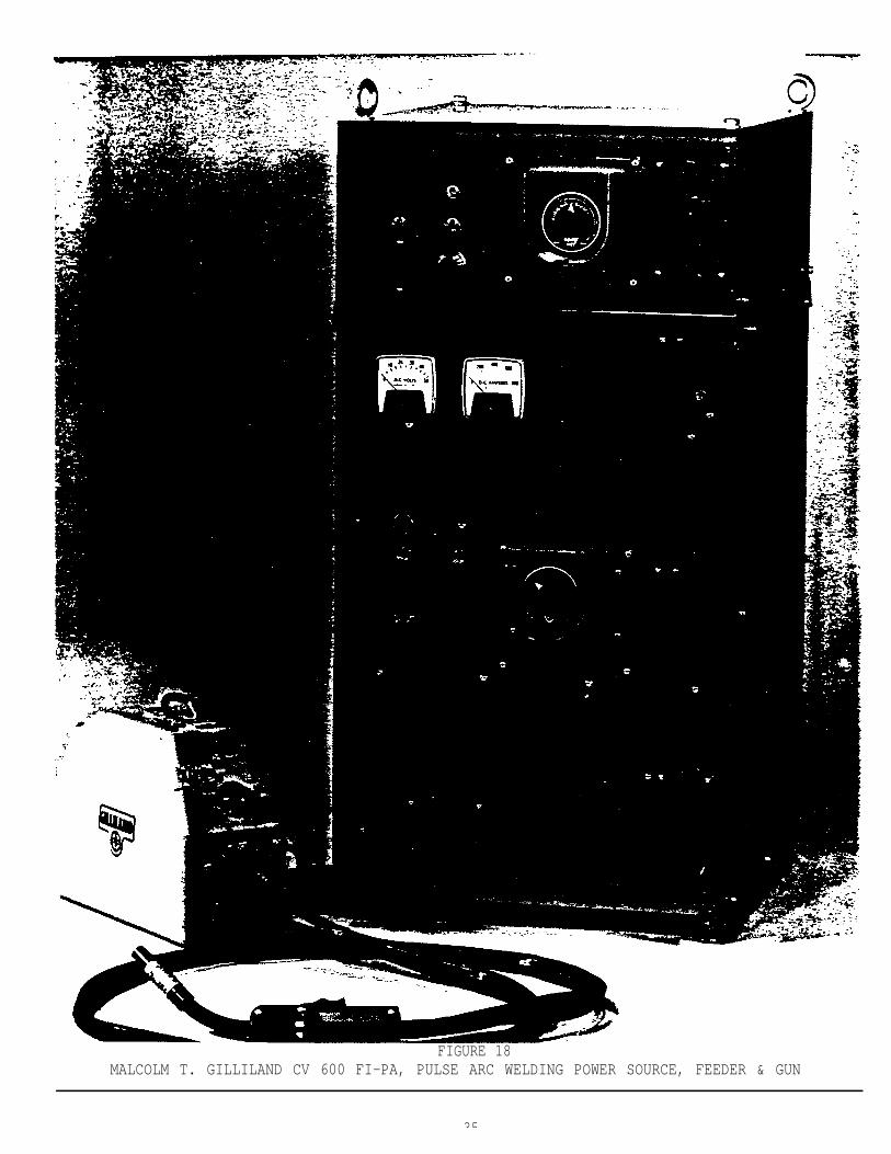
FIGURE 18MALCOLM T. GILLILAND CV 600 FI-PA, PULSE ARC WELDING POWER SOURCE, FEEDER & GUN
35
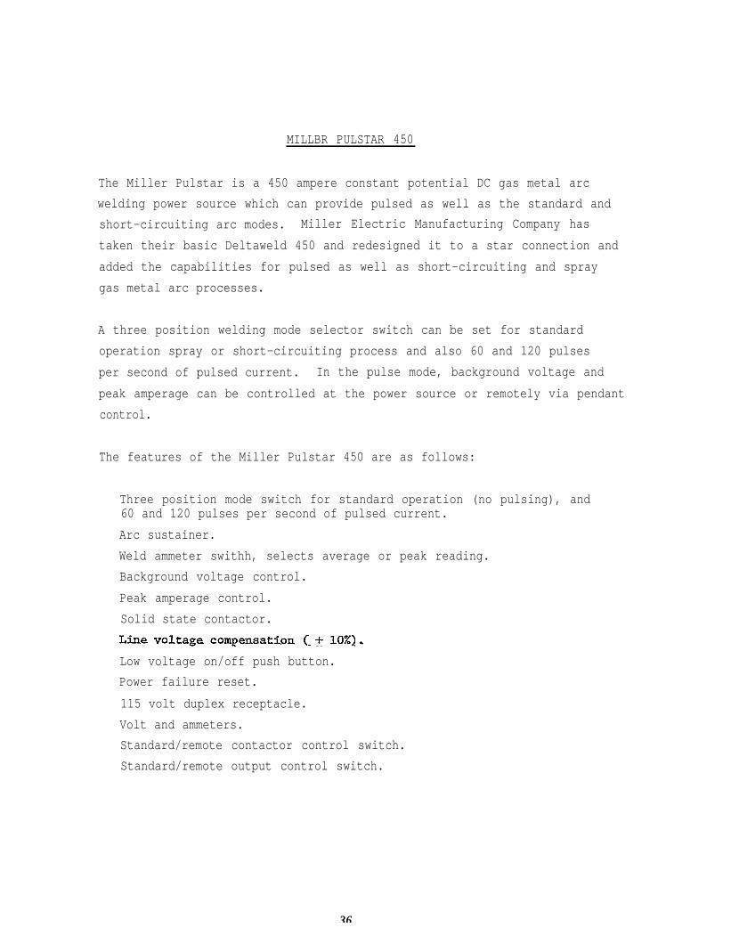
MILLBR PULSTAR 450
The Miller Pulstar is a 450 ampere constant potential DC gas metal arc
welding power source which can provide pulsed as well as the standard and
short-circuiting arc modes. Miller Electric Manufacturing Company has
taken their basic Deltaweld 450 and redesigned it to a star connection and
added the capabilities for pulsed as well as short-circuiting and spray
gas metal arc processes.
A three position welding mode selector switch can be set for standard
operation spray or short-circuiting process and also 60 and 120 pulses
per second of pulsed current. In the pulse mode, background voltage and
peak amperage can be controlled at the power source or remotely via pendant
control.
The features of the Miller Pulstar 450 are as follows:
Three position mode switch for standard operation (no pulsing), and60 and 120 pulses per second of pulsed current.
Arc sustainer.
Weld ammeter swithh, selects average or peak reading.
Background voltage control.
Peak amperage control.
Solid state contactor.
Low voltage on/off push button.
Power failure reset.
115 volt duplex receptacle.
Volt and ammeters.
Standard/remote contactor control switch.
Standard/remote output control switch.
36
The Miller Pulstar 450 power source specification and
are shown in Figure 19. The volt ampere curve and the
are shown in Figures 20 and 21.
On the Miller Pulstar 450 field test power source unit,
items are visible:
physical information
duty cycle chart
the following
Remote contactor control.
115 volts AC receptacles (3).
DC voltmeter (0-100 volts).
DC ammeter (0-600 amperes).
Switch to set for 120 pps, 60 pps and standard (no pulse).
Power on/off buttons.
Remote output control (remote vs. standard).
Remote contactor control remote vs. standard).
Peak amperage adjustment potentiometer (200-550 amperes).
Background voltage adjustment (minimum-38 volts).
* * * * * *
PULSE GMAW: POWER SOURCES: ATTRIBUTES
A chart covering the basic attributes of each of these four pulse GMAW
power sources discussed previously is illustrated in Figure 22. Also,
the pulse GMAW power sources and feeders used in this project are shown
in Figure 23.
37
41
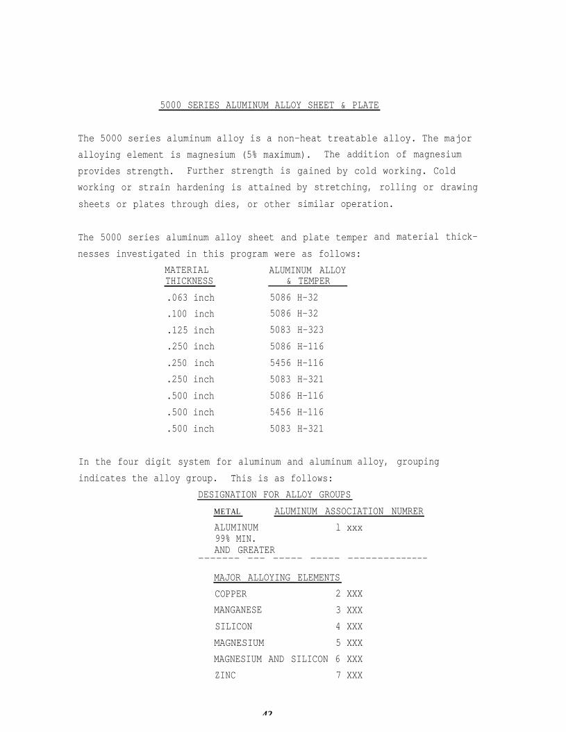
5000 SERIES ALUMINUM ALLOY SHEET & PLATE
The 5000 series aluminum alloy is a non-heat treatable alloy. The major
alloying element is magnesium (5% maximum). The addition of magnesium
provides strength. Further strength is
working or strain hardening is attained
sheets or plates through dies, or other
gained by cold working. Cold
by stretching, rolling or drawing
similar operation.
The 5000 series aluminum alloy sheet and plate temper
nesses investigated in this program were as follows:
and material thick-
MATERIAL ALUMINUM ALLOYTHICKNESS & TEMPER
.063 inch 5086 H-32
.100 inch 5086 H-32
.125 inch 5083 H-323
.250 inch 5086 H-116
.250 inch 5456 H-116
.250 inch 5083 H-321
.500 inch 5086 H-116
.500 inch 5456 H-116
.500 inch 5083 H-321
In the four digit system for aluminum and aluminum
indicates the alloy group. This is as follows:
DESIGNATION FOR ALLOY GROUPS
alloy, grouping
METAL ALUMINUM ASSOCIATION NUMRER
ALUMINUM l xxx99% MIN.AND GREATER
------- —-— ——--- -—--- -------—------
MAJOR ALLOYING ELEMENTS
COPPER 2 XXX
MANGANESE 3 XXX
SILICON 4 XXX
MAGNESIUM 5 XXX
MAGNESIUM AND SILICON 6 XXX
ZINC 7 XXX
42
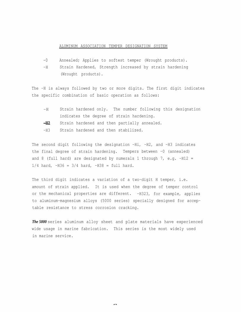
ALUMINUM ASSOCIATION TEMPER DESIGNATION SYSTEM
-0 Annealed; Applies to softest temper (Wrought products).
-H Strain Hardened, Strength increased by strain hardening
(Wrought products).
The -H is always followed by two or more digits. The first digit indicates
the specific combination of basic operation as follows:
-H Strain hardened only. The number following this designation
indicates the degree of strain hardening.
Strain hardened and then partially annealed.
-H3 Strain hardened and then stabilized.
The second digit following the designation -Hi, -H2, and -H3 indicates
the final degree of strain hardening. Tempers between -0 (annealed)
and 8 (full hard) are designated by numerals 1 through 7, e.g. -H12 =
1/4 hard, -H36 = 3/4 hard, -H38 = full hard.
The third digit indicates a variation of a two-digit H temper, i.e.
amount of strain applied. It is used when the degree of temper control
or the mechanical properties are different. -H323, for example, applies
to aluminum-magnesium alloys (5000 series) specially designed for accep-
table resistance to stress corrosion cracking.
The 5000 series aluminum alloy sheet and plate materials have experienced
wide usage in marine fabrication. This series is the most widely used
in marine service.
43
5083 ALUMINUM ALLOY
This alloy is a strong weldable alloy used primarily in armor and cry-
ogenic applications. There are no restrictions for use in marine environ-
ment but it is not recommended to be used for applications involving temper-
atures above 150F.
5086 ALUMINUM ALLOY
This weldable alloy is generally used in hull and superstructure and meets
general marine fabrication requirements. There are no restrictions for
use in marine environment but it is not recommended for use in applications
over 150F. 5086 H-116 aluminum alloys are used in hull fabrication.
5456 ALUMINUM ALLOY
This weldable alloy offers the highest strength and is used primarily
for hulls, superstructures and special purpose vehicles where high
strength-to-weight ratio is desired, e.g. air cushion vehicles and hydro-
foils. The 5456 H-116 aluminum alloy is used for hull applications.
This alloy is not recommended for use in application over 150F but other-
wise there are no restrictions for use in marine environment.
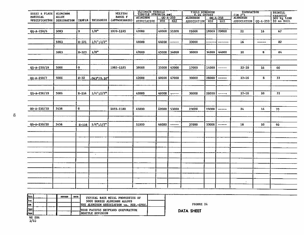
Typical mechanical properties data for 5000 series aluminum alloy sheet
and plate per U.S. Federal Specifications vs. The Aluminum Association
are compared in Figure 24.
44
ALUMINUM ALLOY FILLER WIRES
In general, for welding 5000 series aluminum alloy sheet and plate, the
Plans (Drawings) will, unless otherwise specified, permit the fabricator
to use interchangeably ER 5183, 5356 or 5556 per ASTM/AWS 5.10, “Specifi-
cation For Aluminum and Aluminum Alloy Bare Welding Rods and Electrodes.”
The prefix ER is used by AWS to denote “Electrode/Rod” to cover both the
gas metal arc welding GMAW or the gas tungsten arc welding GTAW process.
For this project, only the ASTM/AWS ER 5356 and 5556 aluminum alloy bare
wires in 12 inch diameter spools (10-12 lbs.) were used, i.e. ER 5183
filler wires were not available Without schedule impact. ASTM/AWS 5.10
requirements covering chemical composition for ER 5356 and 5556 are shown
in Figure 25.
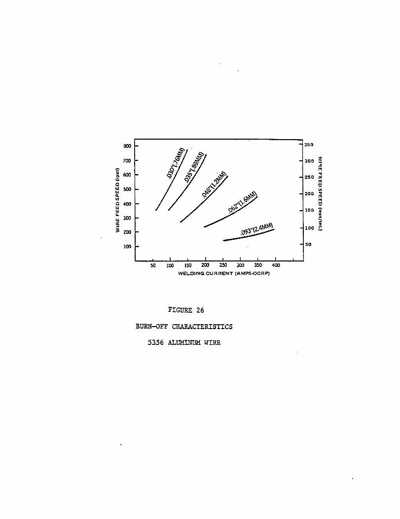
Burn off characteristics of 5356 aluminum alloy filler wires are illustrat-
ed in Figure 26.
The weld is a composite or alloy of the filler material and the base
material. This composite largely determines the mechanical properties
of the weld. Also, the gas metal arc process does leave an annealed
condition weld area. Weld joint configuration, weld filler wire types
and welding techniques are other variables that must be considered.
High. magnesium gas metal arc filler wires such as ER 5183, 5356 and 5556
generally produce strong ductile welds.
Usually the “as welded" tensile strengths of the 5000 series aluminum-
magnesium alloy welds are equal to the strength of the annealed base
material. The only way to strengthen “as welded” tensile strength in
5000 series aluminum is to cold work, e.g. roll-planishing, which is not
practical in a shipyard setting.
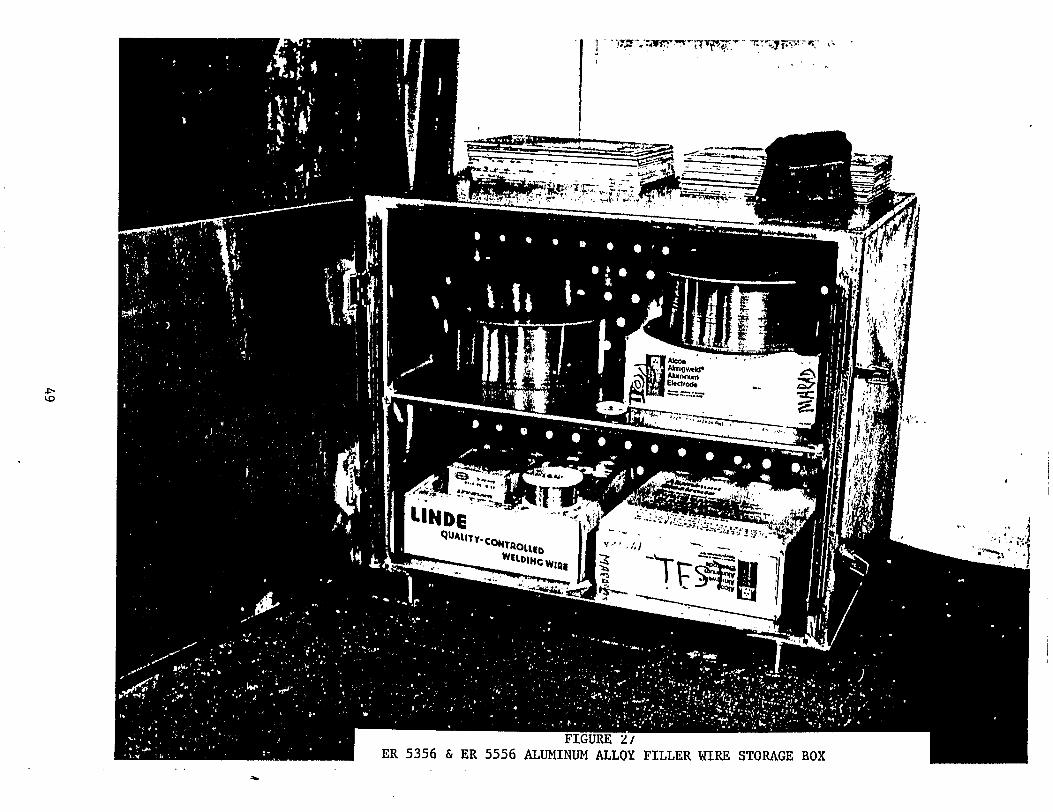
All aluminum alloy filler materials when opened were kept in a dry warm
storage box. This is illustrated in Figure 27. Only Alcoa "Almigweld"
aluminum alloy filler wires were utilized.
46
WELD JOINT DESIGNS
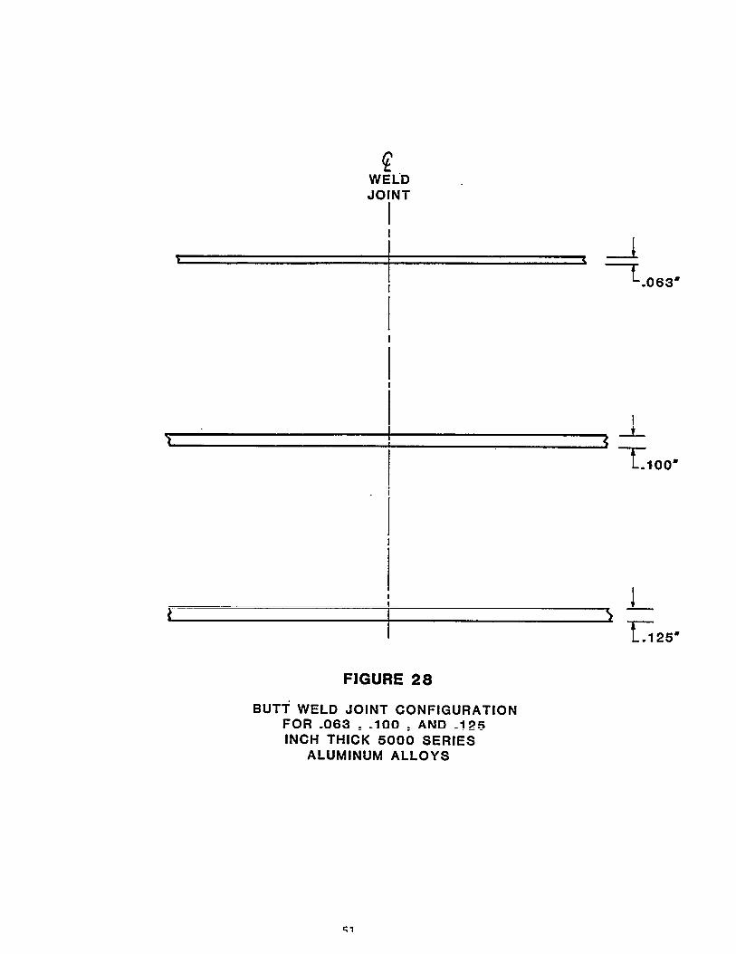
Square butt weld joint designs were used on the .063, .10, and .125 inch
thick 5000 series aluminum
for square butt weld joint
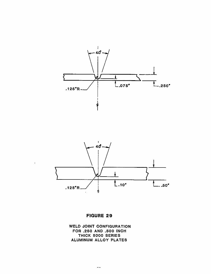
The .250 inch and the .500
alloy sheet test piece parts. See Figure 28
design.
inch thick aluminum alloy plates were machined
with "J” type weld joint designs. Initially,
root face was .075 inch and .100 inch for the
thicknesses as illustrated in Figure 29. The
design was based primarily on the consistency
the dimensioning of the
.250 and .500 inch material
final or preferred joint
and reliability towards
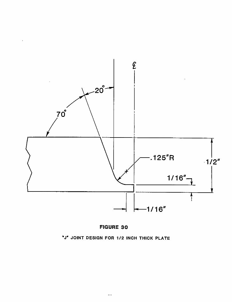
attaining out-of-position, one-side, full penetration welds. See Figure
30, which illustrates the “J” joint configuration used on 1/2 inch material
thicknesses. The 1/16 inch width of flat dimension between the centerline
of the weld joint and the tangent point of the .125 inch radius was shorten-
ed as required to provide acceptable weld bead reinforcements. This is
illustrated on the individual Welding Procedure Qualification Test Summary
pages further in the text.
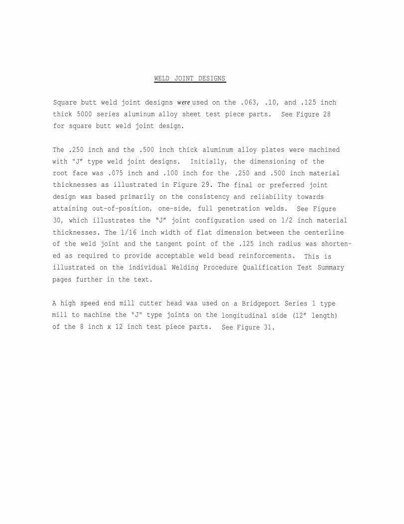
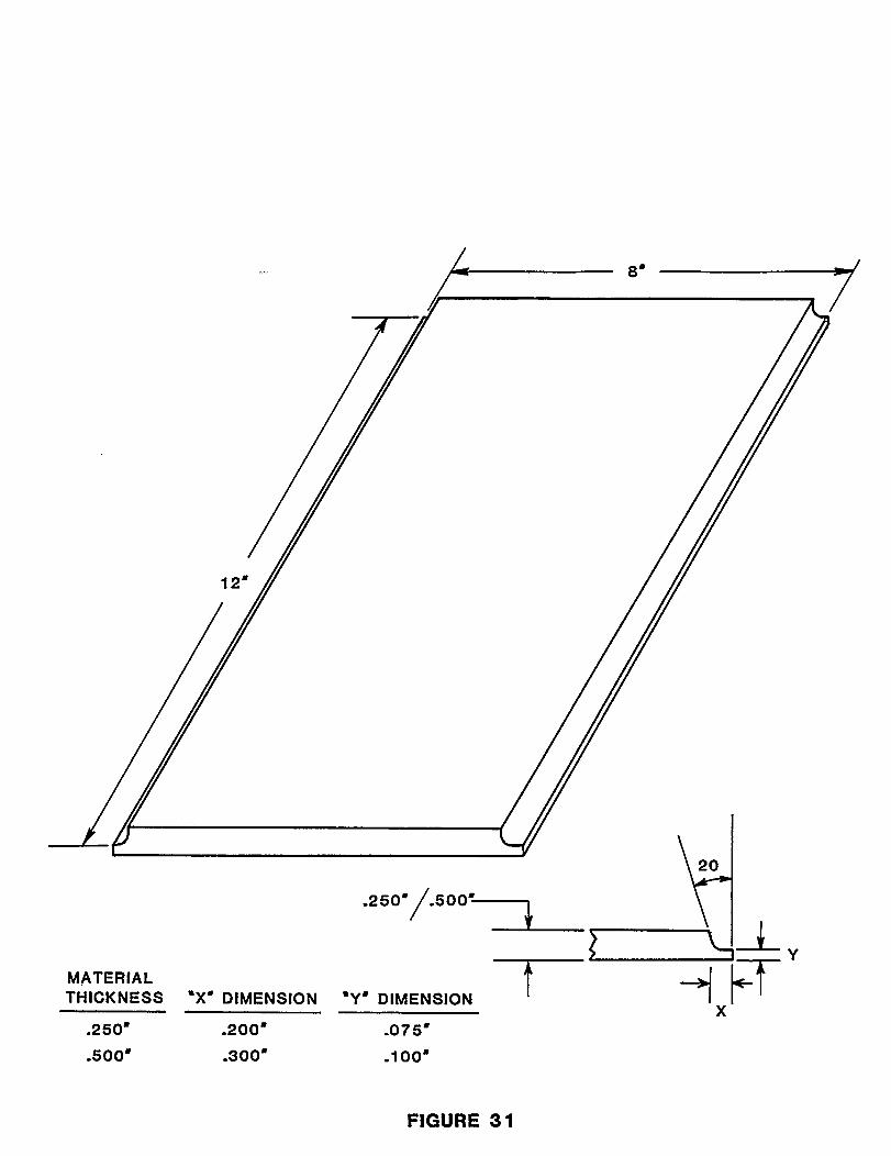
A high speed end mill cutter head was used
mill to machine the "J" type joints on the
of the 8 inch x 12 inch test piece parts.
on a Bridgeport Series 1 type
longitudinal side (12” length)
See Figure 31.
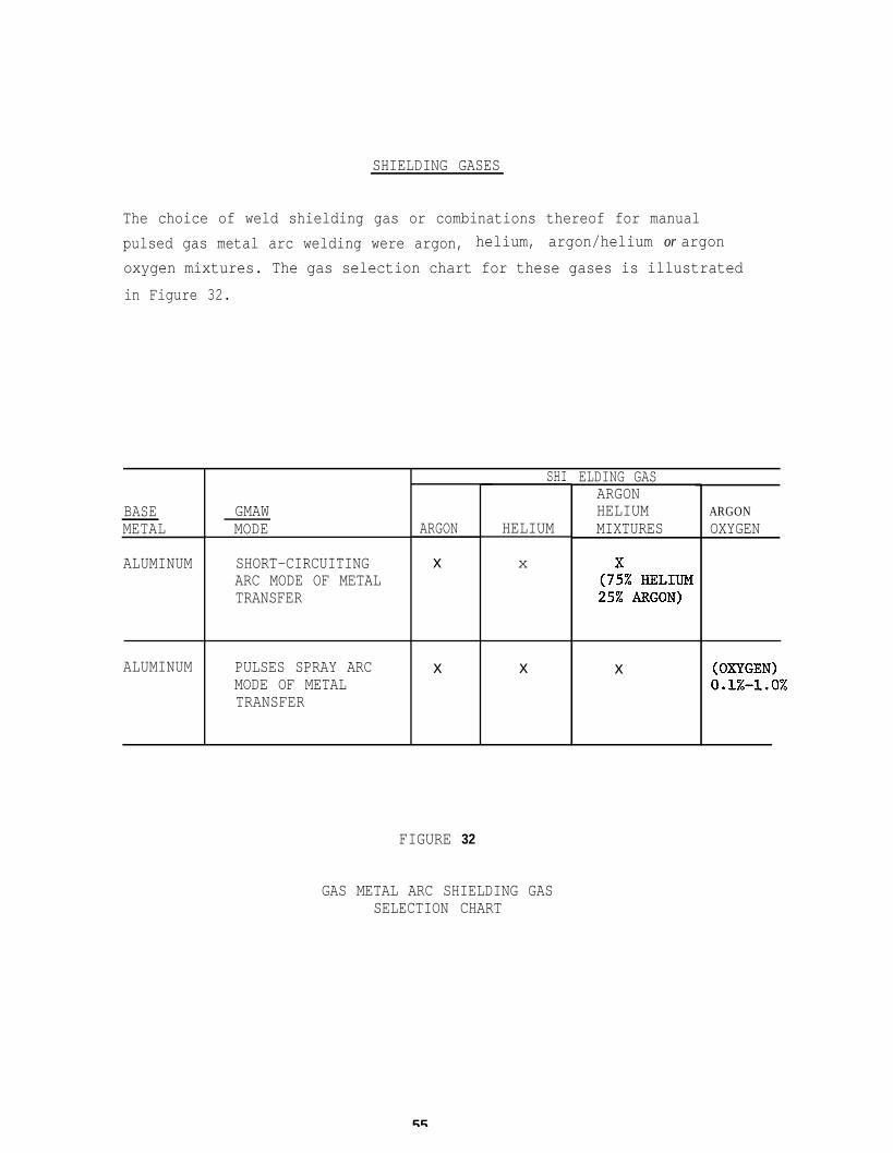
SHIELDING GASES
The choice of weld shielding gas or combinations thereof for manual
pulsed gas metal arc welding were argon, helium, argon/helium or argon
oxygen mixtures. The gas selection chart for these gases is illustrated
in Figure 32.
BASEMETAL
ALUMINUM
ALUMINUM
GMAWMODE
SHORT-CIRCUITINGARC MODE OF METALTRANSFER
PULSES SPRAY ARCMODE OF METALTRANSFER
ARGON
x
x
FIGURE 32
SHI
HELIUM
x
x
ELDING GASARGONHELIUMMIXTURES
x
ARGONOXYGEN
GAS METAL ARC SHIELDING GASSELECTION CHART
55
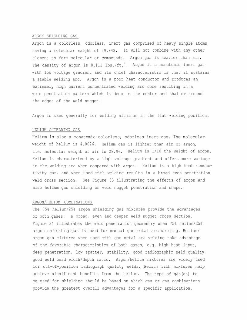
ARGON SHIELDING GAS
Argon is a colorless, odorless, inert gas comprised of heavy single atoms
having a molecular weight of 39.948. It will not combine with any other
element to form molecular or compounds. Argon gas is heavier than air.
The density of argon is 0.111 lbs./ft.3. Argon is a monatomic inert gas
with low voltage gradient and its chief characteristic is that it sustains
a stable welding arc. Argon is a poor heat conductor and produces an
extremely high current concentrated welding arc core resulting in a
weld penetration pattern which is deep in the center and shallow around
the edges of the weld nugget.
Argon is used generally for welding aluminum in the flat welding position.
HELIUM SHIELDING GAS
Helium is also a monatomic colorless, odorless inert gas. The molecular
weight of helium is 4.0026. Helium gas is lighter than air or argon,
i.e. molecular weight of air is 28.96. Helium is 1/10 the weight of argon.
Helium is characterized by a high voltage gradient and offers more wattage
in the welding arc when compared with argon. Helium is a high heat conduc-
tivity gas, and when used with welding results in a broad even penetration
weld cross section. See Figure 33 illustrating the effects of argon and
also helium gas shielding on weld nugget penetration and shape.
ARGON/HELIUM COMBINATIONS
The 75% helium/25% argon shielding gas mixtures provide the advantages
of both gases: a broad, even and deeper weld nugget cross section.
Figure 34 illustrates the weld penetration geomentry when 75% helium/25%
argon shielding gas is used for manual gas metal arc welding. Helium/
argon gas mixtures when used with gas metal arc welding take advantage
of the favorable characteristics of both gases, e.g. high heat input,
deep penetration, low spatter, stability, good radiographic weld quality,
good weld bead width/depth ratio. Argon/helium mixtures are widely used
for out-of-position radiograph quality welds. Helium rich mixtures help
achieve significant benefits from the helium. The type of gas(es) to
be used for shielding should be based on which gas or gas combinations
provide the greatest overall advantages for a specific application.
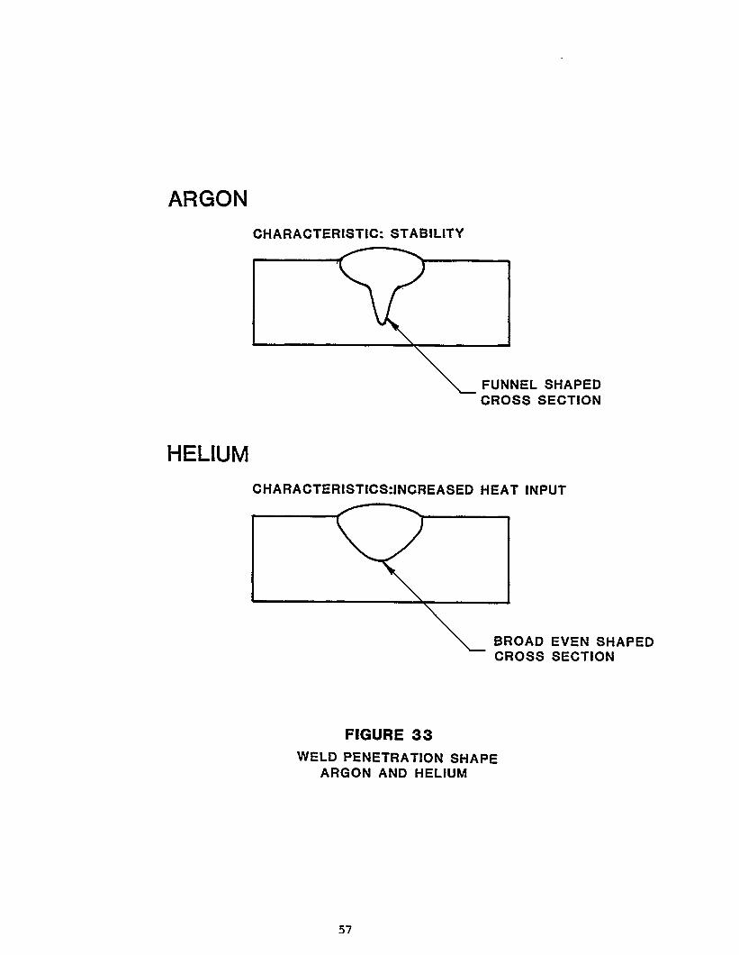
HELIUM-ARGON MIXTURECHARACTERISTICS: GOOD WELD BEAD SHAPE
GOOD WIDTH/DEPTH RATIOCROSS SECTION
FIGURE 34
HELIUM-ARGON MIXTUREWELD PENETRATION GEOMETRY
58
The
25%
per
The
gas
shielding gas used for this project was primarily limited to 75% helium/
argon combinations. Argon gas was per MIL-A-18455 and helium gas was
Federal Specification BB-H-1168, Grade A.
basic reason for the choice
was because past experience
testing quality levels could be
manual gas metal arc welding of
of 75% helium/25% argon combination shielding
had indicated that acceptable radiograph
more readily obtained for all-position
5000 series aluminum alloys. However, on
.500 inch thick aluminum alloy material 100% helium shielding gas was
utilized to make excellent welds. With the increased material thicknesses,
it was felt that better sidewall fusion could be attained in the full
penetration root passes as well as in the multiple
In general, the 75% helium/25% argon shielding gas
fill passes.
mixture, as well as
the straight helium gases, were preferred because good width/depth ratio
could be attained in the weld cross sections. This type of weld cross
section with almost parallel side wall also offered less distortion, i.e.
more balanced heat input.
59
MATERIAL PREPARATION
A cutting diagram was developed for 5000 series aluminum alloy sheet and
plate materials ranging from 1/16 inch, .100 inch, .125 inch, .250 inch
and .500 inch thicknesses and were all sheared into 8 inch x 12 inch
piece parts to be butt welded on the 12 inch side to make 12 inch x 16
inch butt welded test panels. All the shearing of the test piece parts
(8 inch x 12 inch) were done in either the
No. 1010 or the Cincinnati Inc., hydraulic
(“grain”) was transverse to the weld joint
diagram is illustrated in Figure 35.
Wysong and Miles Co., Model
shears. The rolling direction
centerline. A typical cutting
All aluminum alloy sheet material up to and including .125 inch thicknesses
were draw filed with a bastard vixen type file so that all sharp edges,
shear marks, and lamination that could cause deleterious effects in the
weld were completely removed. Mechanical sanding, chipping, machining,
routing are other alternative methods used for weld joint preparation.
See Figure 36.
Methyl-ethyl-ketone (MEK] was applied with a clean rag around the weld
joint areas and surface to ensure that it was free of grease, oil,
moisture, paint, shop soil, or other harmful matter. It should be pointed
out that MEK may not be approved for use in confined, closed areas,
i.e. alternate approved solvents should be used in production applications
such as Dow Chemical Chlorothene VG. Decreasing with an approved solvent
prior to and after mechanical cleaning appeared best.
62
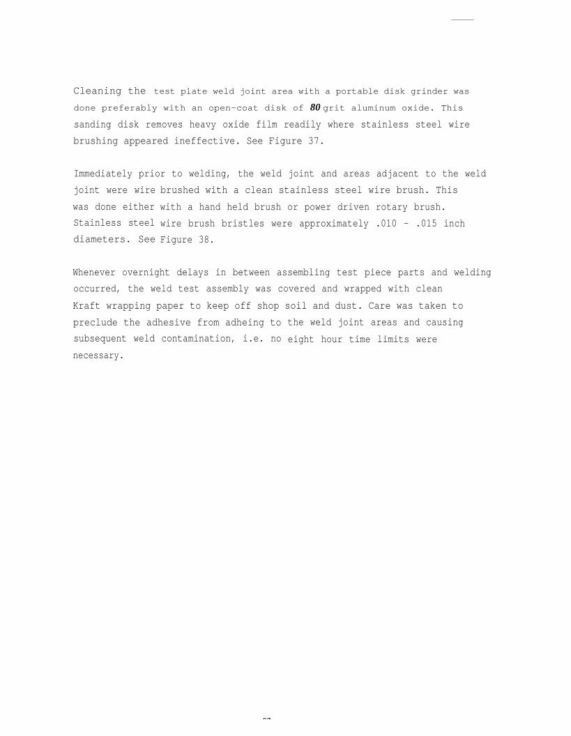
Cleaning the test plate weld joint area with a portable disk grinder was
done preferably with an open-coat disk of 80 grit aluminum oxide. This
sanding disk removes heavy oxide film readily where stainless steel wire
brushing appeared ineffective. See Figure 37.
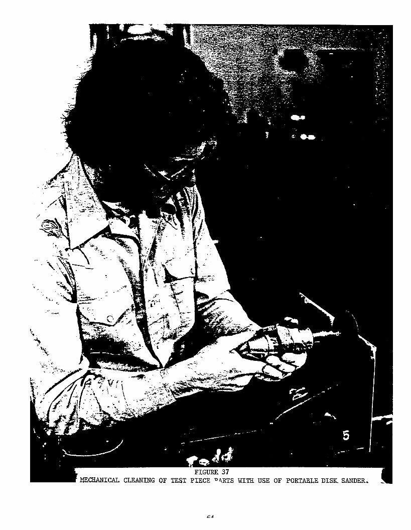
Immediately prior to welding, the weld joint and areas adjacent to the weld
joint were wire
was done either
Stainless steel
diameters. See
brushed with a clean stainless steel wire brush. This
with a hand held brush or power driven rotary brush.
wire brush bristles were approximately .010 - .015 inch
Figure 38.
Whenever overnight delays in between assembling test piece parts and welding
occurred, the weld test assembly was covered and wrapped with clean
Kraft wrapping paper to keep off shop soil and dust. Care was taken to
preclude the adhesive from adheing to
subsequent weld contamination, i.e. no
necessary.
the weld joint areas and causing
eight hour time limits were
63
64
65

WELD JOINT FIT-UP
Weld joint fit-up preferably should be metal to metal, i.e. zero gap.
The maximum butt joint gap allowed anywhere over the length of the weld
joint should be as follows:
MATERIAL THICKNESS(T) MAXIMUM JOINT ROOT OPENING (GAP)
up to .125 inch 1/4 T
.125 inch and thickner .030 inch
Weld joint fit-up requirements per NAVSEA 0900-000-1000/0001, “Fabrica-
tion, Welding and Inspection of Ships’ Hulls,” are as follows:
MATERIAL THICKNESS
less than .375 inch 1/16
.375 inch and thicker 1/8
Obviously, these requirements were written for stick electrode welding
and are inadequate and not in consideration of the newer welding pro-
cesses or thinner sheet materials.
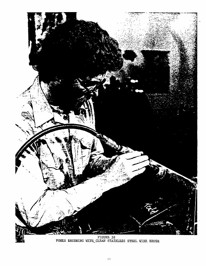
All test piece parts were manual GMAW tack welded together with weld
start and weld stop tabs. All the butt welds were made on the side
opposite the tack welds, i.e. both butt and “J” groove weld joints.
See Figure 39.
66
67
WELDING TESTS
This section describes the various welding tests conducted to generate
welding procedure specification qualification data per NAVSHIPS 0900-000-
1000/1, “Fabrication, Welding and Inspection Of Ship Hulls,” and MIL-
STD-oo248 (SHIPS), “Welding Procedure and Performance Qualification,”
for the out-of-position, one-side, full penetration manual pulsed gas metal
arc welding of 5000 series aluminum alloy sheet and plate for marine
fabrication.
The welding variables involved in this investigation covered the follow-
ing:
1. 5000 series aluminum alloy base material type & temper,
5083 H-321
5083 H-323
5086 H-116
5456 H-116
2. 5000 series aluminum alloy sheet and plate thicknesses,
.060 inch
.100 inch
.125 inch
.250 inch
.500 inch
3. Filler wire alloy and diameters,
5356 aluminum alloy wires
5556 aluminum alloy wires
.030 inch diameter
.035 inch diameter
3/64 inch diameter
1/16 inch diameter
4. Shielding gas & combinations,
75% helium/25% argon
100% argon
100% h li
5. Welding positions:
vertical-up
overhead
horizontal
flat
6. Welding power sources:
Airco PA-3A
Airco PA-350
Miller Pulstar 450
Gilliland CV 600 FI-PA
7. Wire feeders:
Airco AHF-NP
Airco System 1
M & K
Gilliland MTG2000
8. Welding gun (torches):
Airco/Binzel
Airco AH 35 C-2
M & K Cobramatic
Gilliland MTG-4001
Each of the pulse arc welding power sources, wire feeders, guns and accessor-
ies listed above were checked out during an equipment familiarization
period. Scrap aluminum sheet and plate materials were used to make bead
on plate type welds to establish basic welding machine settings for full
penetration butt welds. As confidence levels increased, acceptable butt
weld machine settings were established.
The welding test material flow diagram covering the range from “as procured”
full.
1.
2.
size sheet/plates to destructive testing is illustrated below:
Inspection and lay-out of cutting/shearing diagram for each full size
5000 series aluminum alloy sheet/plate.
Cutting/shearing full size sheet/plate
approximately 8 inches x 12 inches for
into weld test piece parts
.063 inch, .100 inch, .125 inch,
.250 inch and .500 inch thicknesses. Identify each piece part.
30Machine square all 12 inch lengths preparatory for:
a) square butt joint (.063 inch - .125 inch)
b) “J” groove joint (.250 inch - .500 inch)
4. Clean all weld edges and joint areas by degreasing with approved
solventl
5. Mechanically clean by filing, scraping, milling or wire brushing
with clean stainless steel rotary brush or hand brush all weld joint
areas.
6. Manual GMAW tack weld each 8 inch x 12 inch aluminum alloy
piece parts together with weld start/stop tabs to form a 16 inchx
12 inch weld test panel.
7. Manual pulse GMAW in vertical-up, horizontal or overhead welding
position as required.
8. Non-destructive inspection of weld test panels: visual, penrtrant
and radiographic. Reject or accept test panels. If rejected, cut
out weld and recycle to step 3. If accepted, follow step 9.
9. Mill off weld surface and weld underbead from test panels.
10. Lay out and band saw test panels into rough oversize dimensions for
transverse tensiles (2) and bend specimens (4). Steel stamp identi-
fication code.
11. Mill piece parts (rough dimensions) into final dimensions for trans-
verse tensile (2), root bend (2), and face bend test specimens
(2). (See section on Mechanical Properties in this report).
12. Conduct mechanical properties tests. Record data.
13. Evaluate, analyze and summarize weld test results as weld procedure
specification qualification support data.

For clarity’s sake, the reporting together with comments, results, and
recommendations are covered with each specific test grouping. Each grouping
includes the particular 5000 series aluminum alloy and temper, filler wire
diameter and type, type of pulsed welding power source, type of wire feeder,
gun and accessories utilized.
71
5086 H-32 ALUMINUM ALLOY SHEET; .063 & .100 INCH THICKNESSES;AIRCO PA-3A/AHF-NP WIRE FEEDER/AH 35-C2 GUN;
ER 5356 ALUMINUM ALLOY FILLER WIRE
As stated previously in the text, preliminary welding tests were initiated
with use of the Airco PA-3A welding power source, AHF-NP wire feeder and
AH 35-C2 manual GMAW gun. With the use of .035 inch diameter 5356 aluminum
alloy filler wire it was not possible to get radiographically acceptable
welds in the overhead welding position, i.e. Class 1 per NAVSHIPS 0900-
003-9000, “Radiographic Standards for Production and Repair Welds."
On .10 inch thick 5086 H-32 aluminum alloy sheet using .O35 inch diameter
5356 aluminum alloy filler material the vertical and horizontal specimens
welded in the pulse spray mode using Airco PA-3A power supply, AHF-NP
feeder and C-2 gun were not acceptable per radiographic testing. Using
the PA-3A power supply in the pulse spray mode, it appears that overhead
welding is difficult.
Acceptable Weld reinforcements on the second side was not achieyed with
use of the Airco PA-3A, 120 pulses per second, spray arc type transfer
mode. The overhead weld reinforcement shape in .10 inch material thickness
was not acceptable because of an incipient melting condition adjacent to
the edges. This caused a discrepancy appearing similar to that of an
undercut with the weld deposit being thinner than the base material thick-
ness. Gravity appeared to disrupt the surface tension of the weld puddle
causing the molten puddle to drop.
In the overhead position, meeting NAVSHIPS 0900-003-9000, Classl type
procedure qualifications requirements for radiographic acceptance was
difficult. However, there appears to be no problem meeting Class 3,
production welding acceptance standards. Acceptable radiographic produc-
tion quality level welds could be attained on a consistent and reliable
basis.
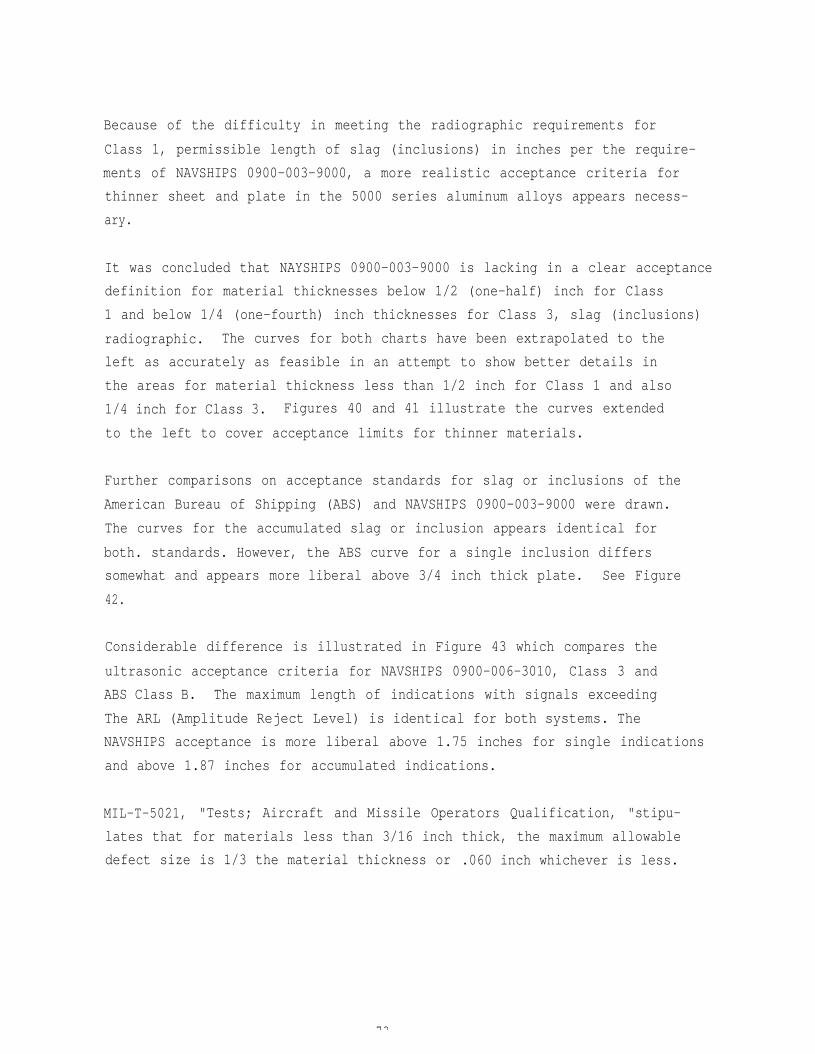
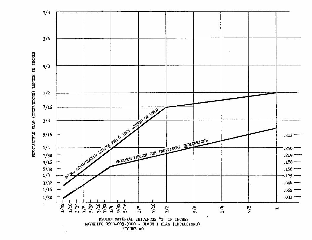
Because of the difficulty in meeting the radiographic requirements for
Class 1, permissible length of slag (inclusions) in inches per the require-
ments of NAVSHIPS 0900-003-9000, a more realistic acceptance criteria for
thinner sheet and plate in the 5000 series aluminum alloys appears necess-
ary.
It was concluded that NAYSHIPS 0900-003-9000 is lacking in a clear acceptance
definition for material thicknesses below 1/2 (one-half) inch for Class
1 and below 1/4 (one-fourth) inch thicknesses for Class 3, slag (inclusions)
radiographic. The curves for both charts have been extrapolated to the
left as accurately as feasible in an attempt to show better details in
the areas for material thickness less than 1/2 inch for Class 1 and also
1/4 inch for Class 3. Figures 40 and 41 illustrate the curves extended
to the left to cover acceptance limits for thinner materials.
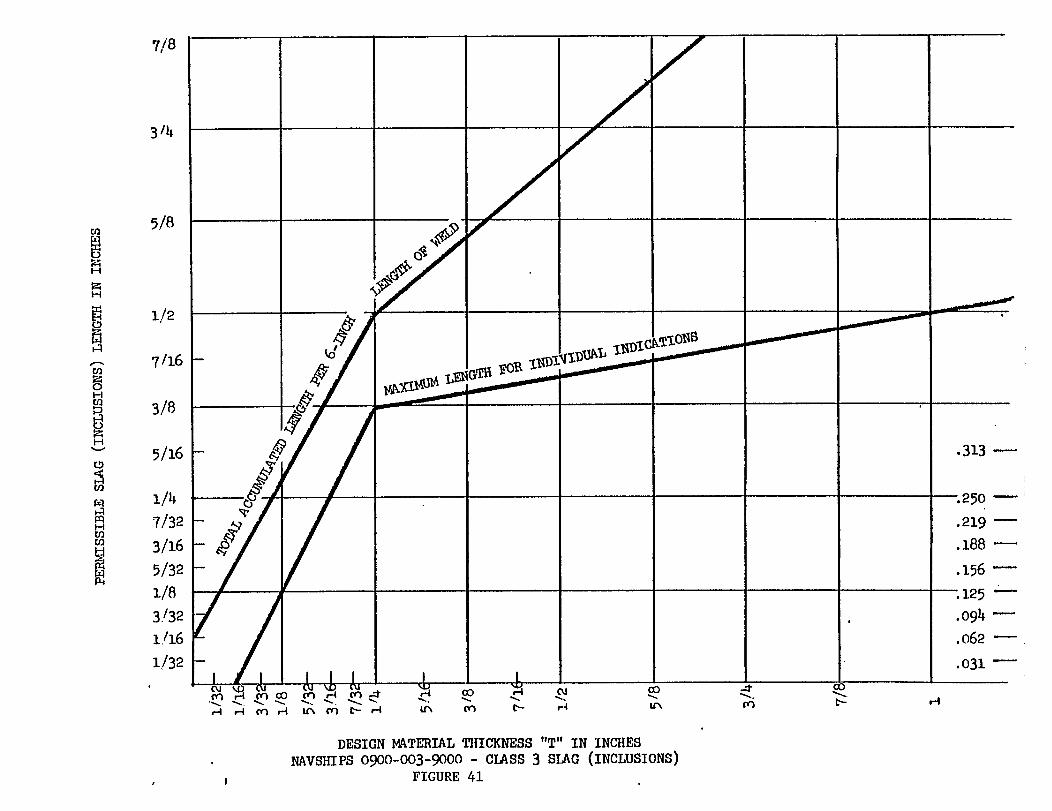
Further comparisons on acceptance standards for slag or inclusions of the
American Bureau of Shipping (ABS) and NAVSHIPS 0900-003-9000 were drawn.
The curves for the accumulated slag or inclusion appears identical for
both. standards. However, the ABS curve for a single inclusion differs
somewhat and appears more liberal above 3/4 inch thick plate. See Figure
42.
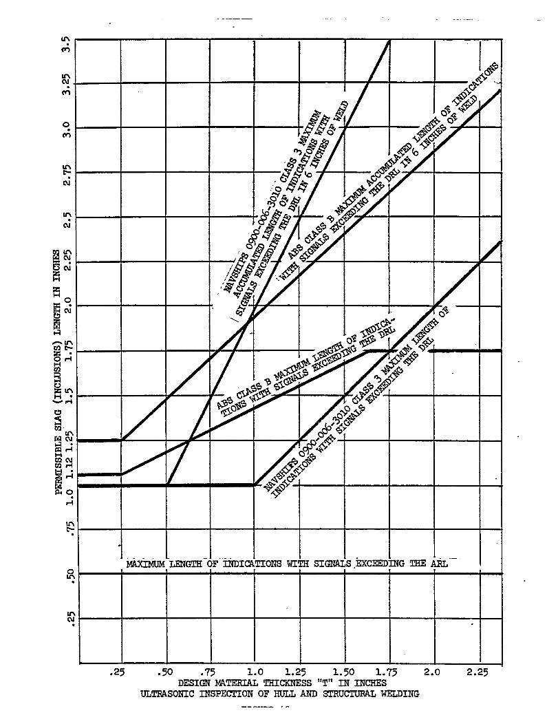
Considerable difference is illustrated in Figure 43 which compares the
ultrasonic acceptance criteria for NAVSHIPS 0900-006-3010, Class 3 and
ABS Class B. The maximum length of indications with signals exceeding
The ARL (Amplitude Reject Level) is identical for both systems. The
NAVSHIPS acceptance is more liberal above 1.75 inches for single indications
and above 1.87 inches for accumulated indications.
MIL-T-5021, "Tests; Aircraft and Missile Operators Qualification, "stipu-
lates that for materials less than 3/16 inch thick, the maximum allowable
defect size is 1/3 the material thickness or .060 inch whichever is less.
73
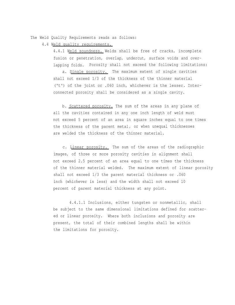
The Weld Quality Requirements reads as follows:
4.4 Weld quality requirements.
4.4.1 Weld soundness. Welds shall be free of cracks, incomplete
fusion or penetration, overlap, undercut, surface voids and over-
lapping folds. Porosity shall not exceed the following limitations:
a. Single porosity. The maximum extent of single cavities
shall not exceed 1/3 of the thickness of the thinner material
("t") of the joint or .060 inch, whichever is the lesser. Inter-
connected porosity shall be considered as a single cavity.
b. Scattered porosity. The sum of the areas in any plane of
all the cavities contained in any one inch length of weld must
not exceed 5 percent of an area in square inches equal to one times
the thickness of the parent metal, or when unequal thicknesses
are welded the thickness of the thinner material.
c. Linear porosity. The sum of the areas of the radiographic
images, of three or more porosity cavities in alignment shall
not exceed 2.5 percent of an area equal to one times the thickness
of the thinner material welded. The maximum extent of linear porosity
shall not exceed 1/3 the parent material thickness or .060
inch (whichever is less) and the width shall not exceed 10
percent of parent material thickness at any point.
4.4.1.1 Inclusions, either tungsten or nonmetallic, shall
be subject to the same dimensional limitations defined for scatter-
ed or linear porosity. Where both inclusions and porosity are
present, the total of their combined lengths shall be within
the limitations for porosity.
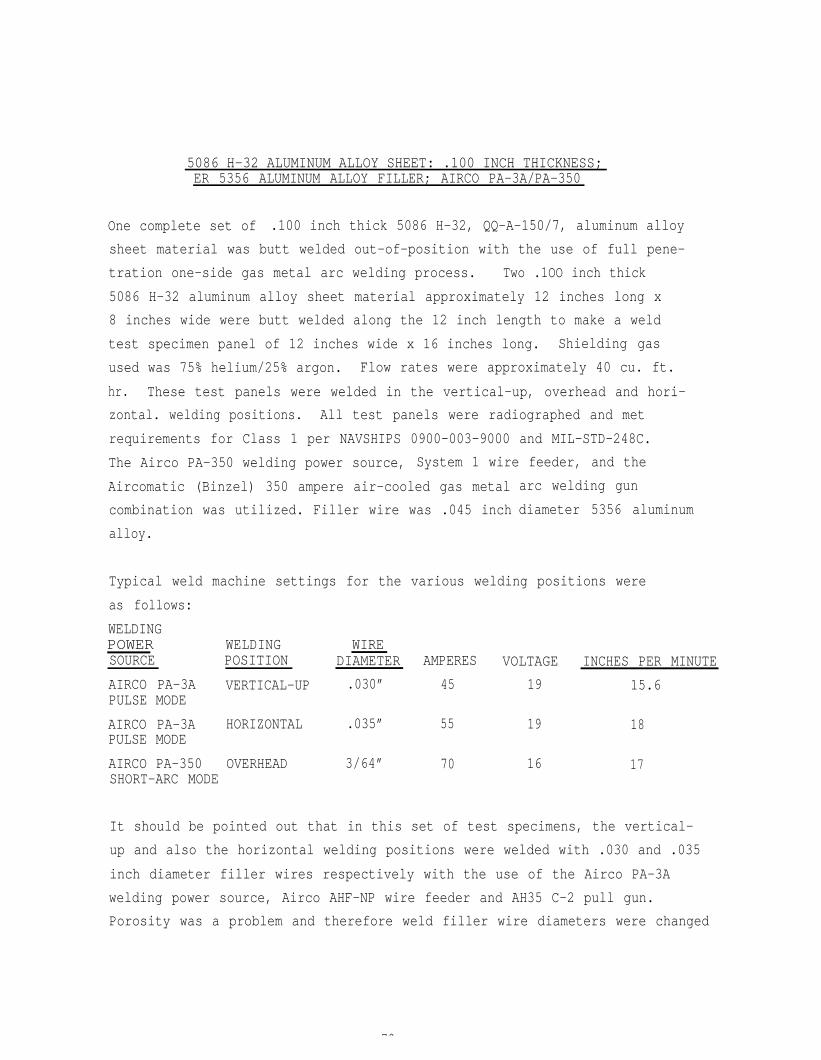
5086 H-32 ALUMINUM ALLOY SHEET: .100 INCH THICKNESS;ER 5356 ALUMINUM ALLOY FILLER; AIRCO PA-3A/PA-350
One complete set of .100 inch thick 5086 H-32, QQ-A-150/7, aluminum alloy
sheet material was butt welded out-of-position with the use of full pene-
tration one-side gas metal arc welding process. Two .1OO inch thick
5086 H-32 aluminum alloy sheet material approximately 12 inches long x
8 inches wide were butt welded along the 12 inch length to make a weld
test specimen panel of 12 inches wide x 16 inches long. Shielding gas
used was 75% helium/25% argon. Flow rates were approximately 40 cu. ft.
hr. These test panels were welded in the vertical-up, overhead and hori-
zontal. welding positions. All test panels were radiographed and met
requirements for Class 1 per NAVSHIPS 0900-003-9000 and MIL-STD-248C.
The Airco PA-350 welding power source, System 1 wire feeder, and the
Aircomatic (Binzel) 350 ampere air-cooled gas metal
combination was utilized. Filler wire was .045 inch
alloy.
arc welding gun
diameter 5356 aluminum
Typical weld machine settings for the various welding positions were
as follows:
WELDINGPOWER SOURCE
WELDING WIREPOSITION DIAMETER AMPERES VOLTAGE INCHES PER MINUTE
AIRCO PA-3A VERTICAL-UP .030” 45 19 15.6PULSE MODE
AIRCO PA-3A HORIZONTAL .035” 55 19 18PULSE MODE
AIRCO PA-350 OVERHEAD 3/64” 70 16 17SHORT-ARC MODE
It should be pointed out that in this set of test specimens, the vertical-
up and also the horizontal welding positions were welded with .030 and .035
inch diameter filler wires respectively with the use of the Airco PA-3A
welding power source, Airco AHF-NP wire feeder and AH35 C-2 pull gun.
Porosity was a problem and therefore weld filler wire diameters were changed
79
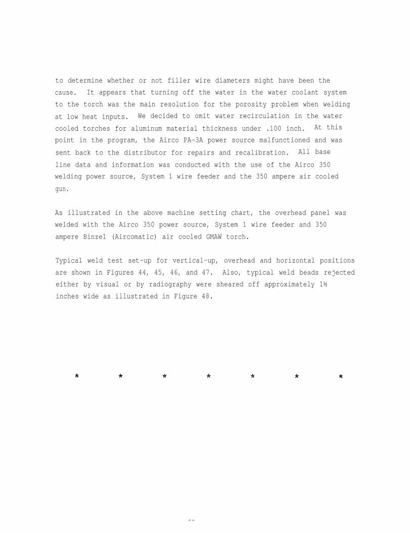
to determine whether or not filler wire diameters might have been the
cause. It appears that turning off the water in the water coolant system
to the torch was the main resolution for the porosity problem when welding
at low heat inputs. We decided to omit water recirculation in the water
cooled torches for aluminum material thickness under .100 inch. At this
point in the program, the Airco PA-3A power source malfunctioned and was
sent back to the distributor for repairs and recalibration. All base
line data and information was conducted with the use of the Airco 350
welding power source, System 1 wire feeder and the 350 ampere air cooled
gun.
As illustrated in the above machine setting chart, the overhead panel was
welded with the Airco 350 power source, System 1 wire feeder and 350
ampere Binzel (Aircomatic) air cooled GMAW torch.
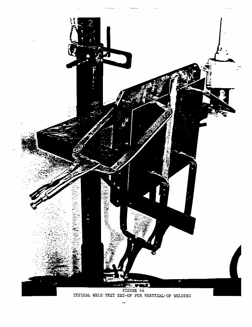
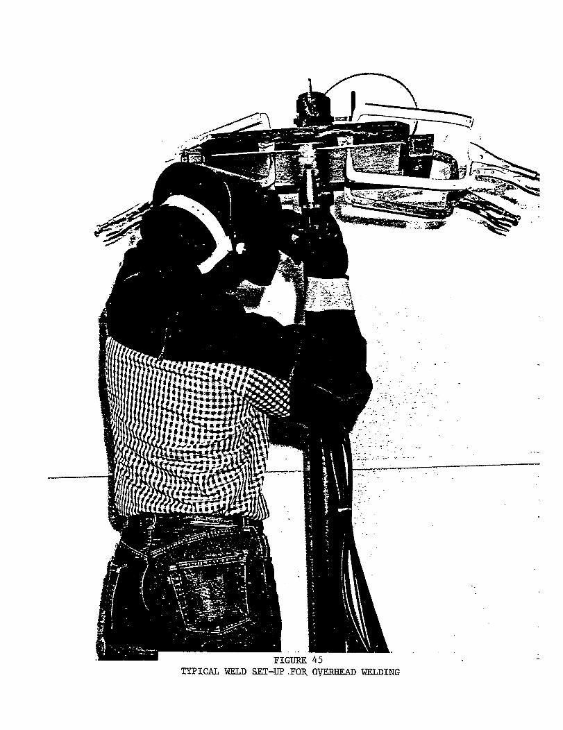
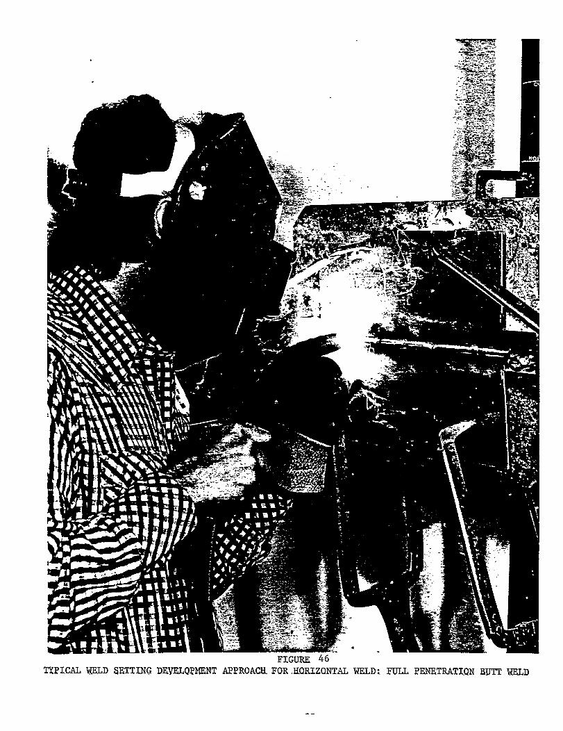
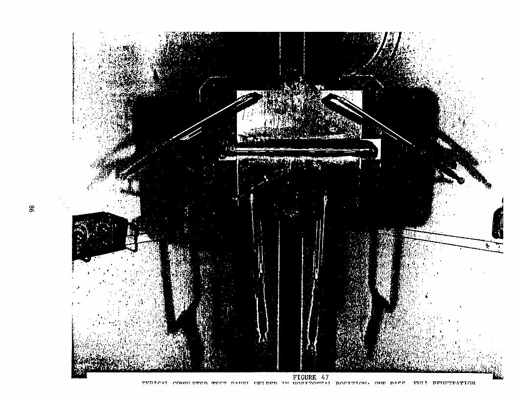
Typical weld test set-up for vertical-up, overhead and horizontal positions
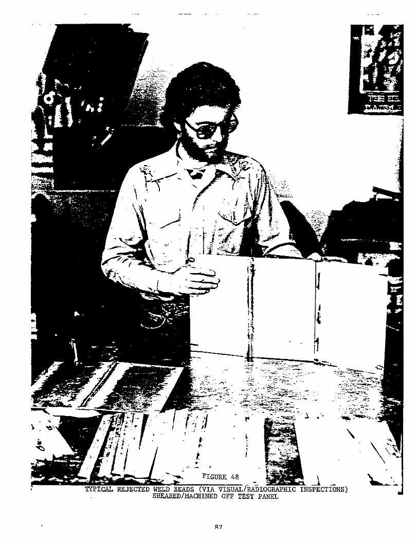
are shown in Figures 44, 45, 46, and 47. Also, typical weld beads rejected
either by visual or by radiography were sheared off approximately 1½
inches wide as illustrated in Figure 48.
80
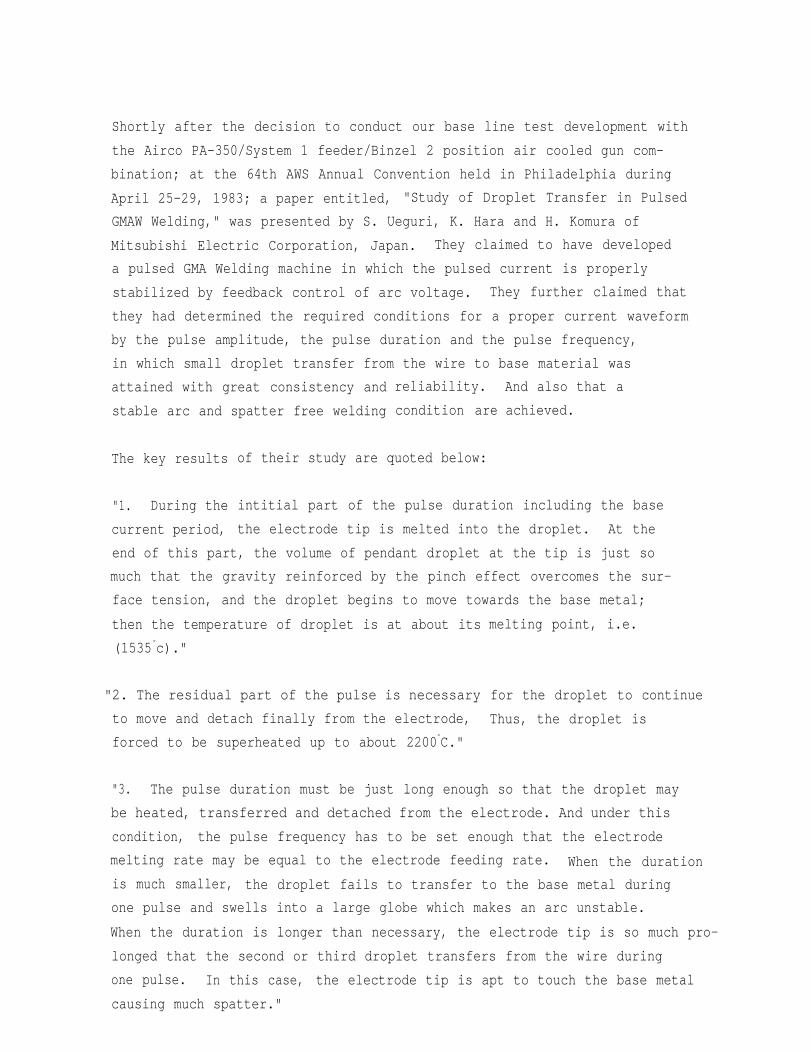
Shortly after the decision to conduct our base line test development with
the Airco PA-350/System 1 feeder/Binzel 2 position air cooled gun com-
bination; at the 64th AWS Annual Convention held in Philadelphia during
April 25-29, 1983; a paper entitled, "Study of Droplet Transfer in Pulsed
GMAW Welding," was presented by S. Ueguri, K. Hara and H. Komura of
Mitsubishi Electric Corporation, Japan. They claimed to have developed
a pulsed GMA Welding machine in which the pulsed current is properly
stabilized by feedback control of arc voltage. They further claimed that
they had determined the required conditions for a proper current waveform
by the pulse amplitude, the pulse duration and the pulse frequency,
in which small droplet transfer from the wire to base material was
attained with great consistency and
stable arc and spatter free welding
reliability.
condition are
And also that a
achieved.
The key results
"1. During the
current period,
of their study are quoted below:
intitial part of the pulse duration including the base
the electrode tip is melted into the droplet. At the
end of this part, the volume of pendant droplet at the tip is just so
much that the gravity reinforced by the pinch effect overcomes the sur-
face tension, and the droplet begins to move towards the base metal;
then the temperature of droplet is at about its
(1535°c)."
"2. The residual part of the pulse is necessary
to move and detach finally from the electrode,
forced to be superheated up to about 2200°C."
melting point, i.e.
for the droplet to continue
Thus, the droplet is
"3. The pulse duration must be just long enough so that the droplet may
be heated, transferred and detached from the electrode. And under this
condition, the pulse frequency has to be set enough that the electrode
melting rate may be equal to the electrode feeding rate. When the duration
is much smaller, the droplet fails to transfer to the base metal during
one pulse and swells into a large globe which makes an arc unstable.
When the duration is longer than necessary, the electrode tip is so much pro-
longed that the second or third droplet transfers from the wire during
one pulse. In this case, the electrode tip is apt to touch the base metal
causing much spatter."
"4. In the case of the spray transfer under the steady direct current,
the arc heat is continuously put into the wire and the wire tip is pro-
longed inevitably. On the other hand, we can get a shorter and stabler
arc by a proper pulsed current described above.”
"5. We calculated the profile of pendant droplet according to Greene's
theory and found a good agreement between the calculated results and the
experimental results observed with high-speed motion picture. Greene's
theory has been developed for the steady direct current and not yet
verified by any experiment. However, in the case of mild steel and stain-
less steel, we consider his theory is more suited for the pulsed current,
since his assumption that the shape of pendant droplet is globular is
more appropriately satisfied with batch input."
* * * * * * *
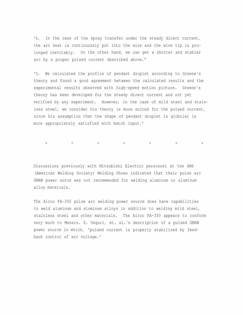
Discussions previously with Mitsubishi Electric personnel at the AWS
(American Welding Society) Welding Shows indicated that their pulse arc
GMAW power surce was not recommended for welding aluminum or aluminum
alloy materials.
The Airco PA-350 pulse arc welding power source does have capabilities
to weld aluminum and aluminum alloys in addition to welding mild steel,
stainless steel and other materials. The Airco PA–350 appears to conform
very much to Messrs. S. Ueguri, et. al.'s description of a pulsed GMAW
power source in which, "pulsed current is properly stabilized by feed-
back control of arc voltage."
An
to
of
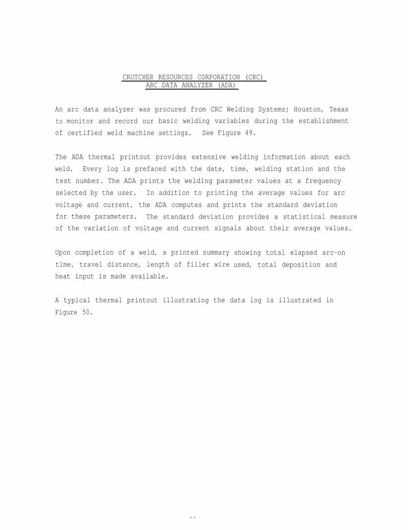
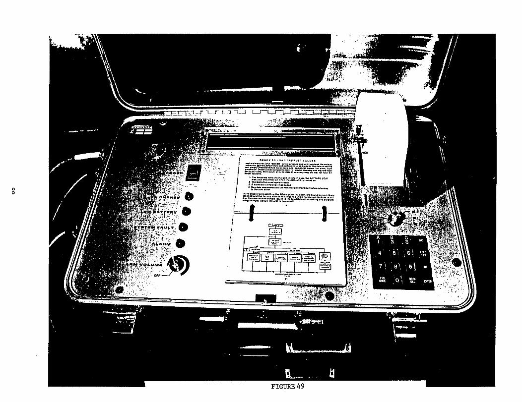
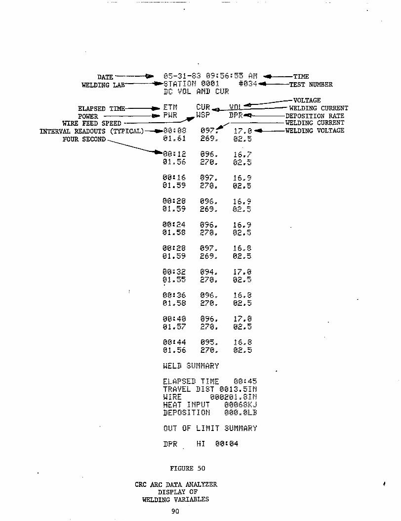
CRUTCHER RESOURCES CORPORATION (CRC)ARC DATA ANALYZER (ADA)
arc data analyzer was procured from CRC Welding Systems; Houston, Texas
monitor and record our
certified weld machine
basic welding variables during the establishment
settings. See Figure 49.
The ADA thermal printout provides extensive welding information about each
weld. Every log is prefaced with the date, time, welding station and the
test number. The ADA prints the welding parameter values at a frequency
selected by the user. In addition to printing the average values for arc
voltage and current, the ADA computes and prints the standard deviation
for these parameters. The standard deviation provides a statistical measure
of the variation of voltage and current signals about their average values.
Upon completion of a weld, a printed summary
time, travel distance, length of filler wire
heat input is made available.
showing total elapsed arc-on
used, total deposition and
A typical thermal printout illustrating the data log is illustrated in
Figure 50.
88
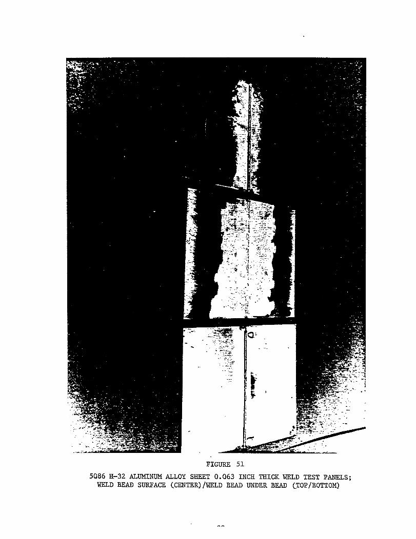
5086 H-32 ALUMINUM ALLOY SHEET: .063 INCH THICKNESS;ER 5556 ALUMINUM ALLOY FILLER WIRE; AIRCO PA-350
One set of .063 inch thick 5086 H-32, QQ-A-150/7, aluminum alloy sheet
material was butt welded out-of-position with the use of the full penetra-
tion one-side gas metal arc welding process. Two 1/16 inch thick x 8 inch
wide x 12 inch long sheets were butt welded to make an approximately 12
inch x 16 inch test panel. See Figure 51, which shows the weld bead surface
and underbead. These weld test panels were subsequently machined into mechani-
cal properties specimens. i.e. Tensiles, root and face bend specimens.
Start and stop tabs approximately 2 inches x 1 inch x .063 inch thickness
of same aluminum alloy as the base materials were used so that maximum
panel length could be used. Shielding gas used was 75% helium/25% argon.
These test panels were welded in the vertical-up, overhead and horizontal
welding positions. No flat (downhand) panels were welded because these
are normally not required for welding procedure qualification. All test
panels were radtographed and met Class 1 requirements per NAVSHIPS 0900-
003-9000 and MIL-STD-248C. The Airco PA-350 welding power source, System
1 wire feeder and Aircomatic (Binzel) 350 ampere air-cooled gas metal arc
gun was utilized. Filler wire was 3/64 inch diameter, 5556 aluminum alloy.
Typical machine settings
WELDINGPOSITION DIAMETER
VERTICAL-UP 3/64 inchOVERHEAD 3/64 inchHORIZONTAL 3/64 inch
for the various welding positions are as follows:
TRAVEL SPEED ALUMINUM ALLOYAMPERE VOLTAGE INCHES PER MINUTE FILLER WIRE
50 15 18 ER 555650 15.5 20 ER 555650 15 18 ER 5556
Specific pertinent machine settings that were used on test panels are covered
later in the section covering weld machine settings.
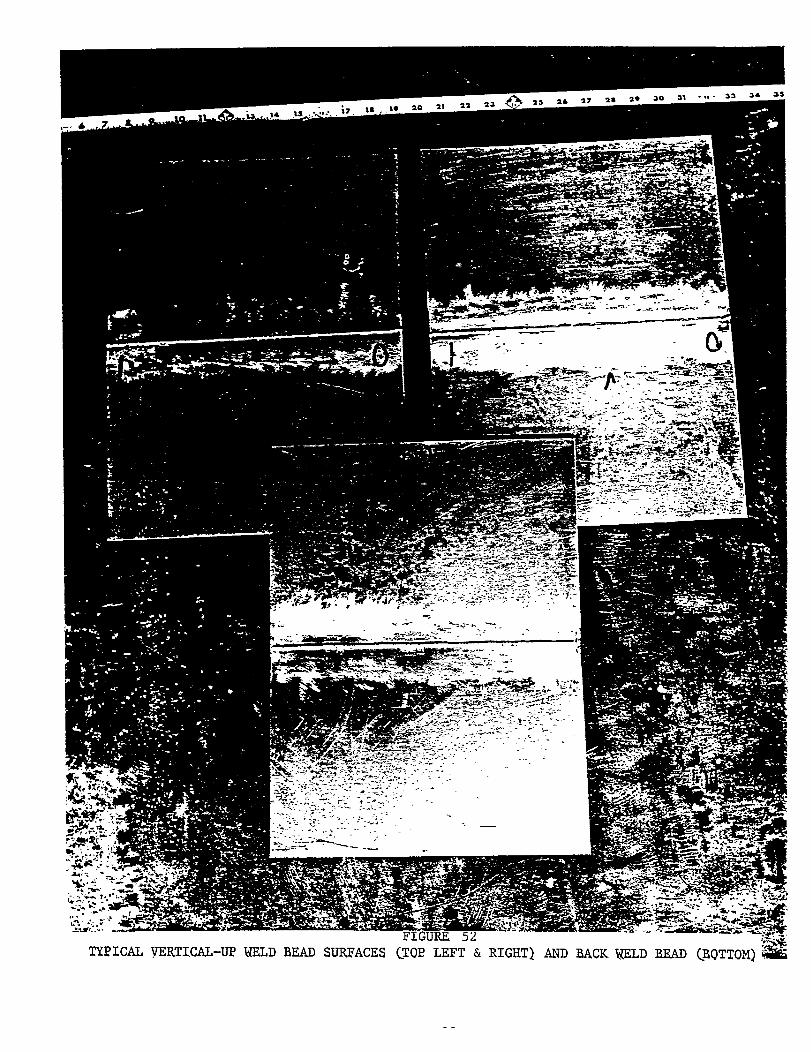
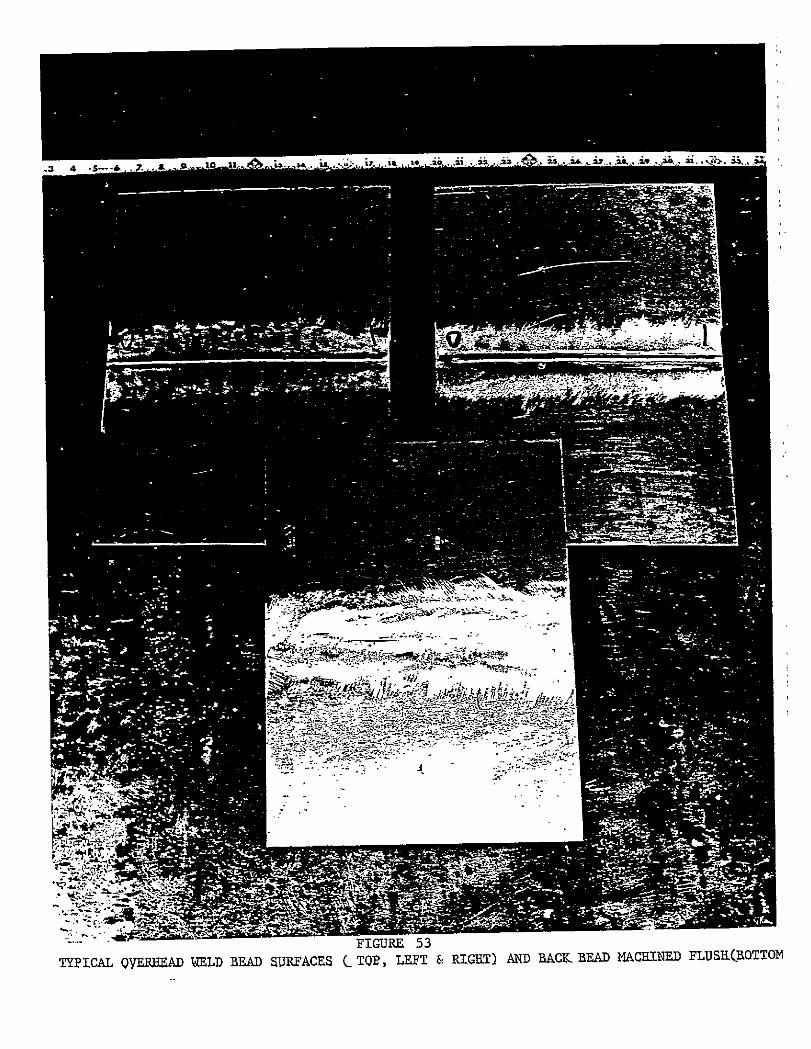
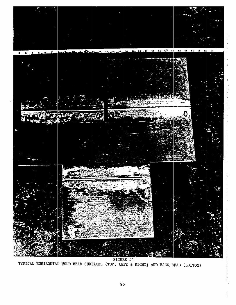
Figures 52, 53, and 54 show the typical weld bead surfaces and also the
penetration bead on the far side.
91
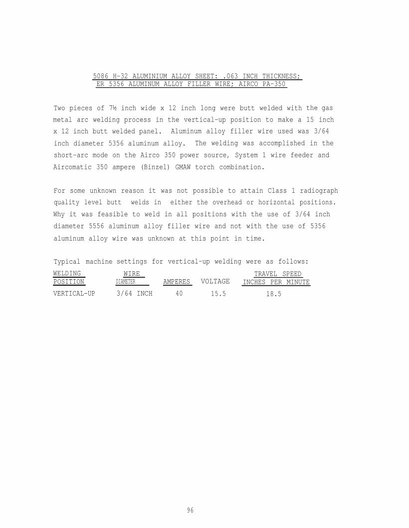
5086 H-32 ALUMINIUM ALLOY SHEET: .063 INCH THICKNESS;ER 5356 ALUMINUM ALLOY FILLER WIRE; AIRCO PA-350
Two pieces of 7½ inch wide x 12 inch long were butt welded with
metal arc welding process in the vertical-up position to make a
the gas
15 inch
x 12 inch butt welded panel. Aluminum alloy filler wire used was 3/64
inch diameter 5356 aluminum alloy. The welding was accomplished in the
short-arc mode on the Airco 350 power source, System 1 wire feeder and
Aircomatic 350 ampere (Binzel) GMAW torch combination.
For some unknown reason it was not possible to attain Class 1 radiograph
quality level butt welds in either the overhead or horizontal positions.
Why it was feasible to weld in all positions with the use of 3/64 inch
diameter 5556 aluminum alloy filler wire and not with the use of 5356
aluminum alloy wire was unknown at this point in time.
Typical machine
WELDINGPOSITION
VERTICAL-UP
settings for vertical-up welding were as follows:
WIRE TRAVEL SPEEDAMPERES VOLTAGEDIAMETER INCHES PER MINUTE
3/64 INCH 40 15.5 18.5
96
5083 H-323 ALUMINUM ALLOY SHEET: .125 INCH THICKNESS:ER 5356 ALUMINUM ALLOY FILLER WIRE; AIRCO PA-350
Out-of-position full penetration gas metal arc butt welding of .125 inch
thick 5083 H-323, QQ-A-250/6, aluminum alloy sheet base material was
completed. Two base metal plates each .125 inch thick x 8 inches wide x
12 inches. long were butt welded to make mechanical properties specimen
test panels 12 inches x 16 inches. All test panels welded were radiographed
to meet Class 1 requirements per NAVSHIPS 0900-003-9000 and MIL-STD-248C.
The Airco PA-350 welding power source, System 1 wire feeder and Airco-
matic (Binzel) 350 ampere air-cooled gas metal arc welding gun equipment
combination was used. Typical short-arc welding machine settings for the
various welding position and filler wire alloy and diameters are shown
below:
FILLER WIREALLOY & DIAMETER
ER 53563/64” dia.
ER 55563/64” dia.
ER 55563/64” dia.
ER 53563/64” dia.
WELDINGPOSITION’ AMPERES
VERTICAL-UP 70
VERTICAL-UP 70
HORIZONTAL 85
105
VOLTAGE
17
17
19.5
15
TRAVEL SPEEDINCHES PER MINUTE
14.1
12.8
1.5
20
97
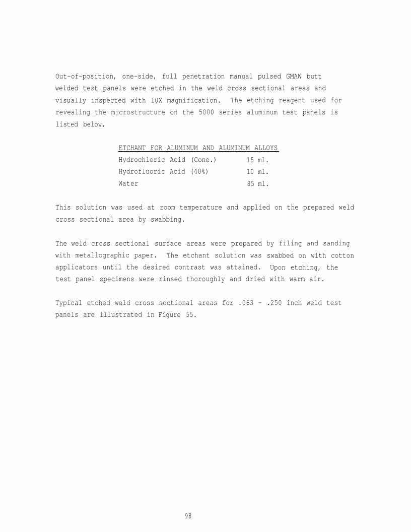
Out-of-position, one-side, full penetration manual pulsed GMAW butt
welded test panels were etched in the weld cross sectional areas and
visually inspected with 10X magnification. The etching reagent used for
revealing the microstructure on the 5000 series aluminum test panels is
listed below.
ETCHANT FOR ALUMINUM AND ALUMINUM ALLOYS
Hydrochloric Acid (Cone.) 15 ml.
Hydrofluoric Acid (48%) 10 ml.
Water 85 ml.
This solution was used at room temperature and applied on the prepared weld
cross sectional area by swabbing.
The weld cross sectional surface areas were prepared
with metallographic paper. The etchant solution was
applicators until the desired contrast was attained.
test panel specimens were
Typical etched weld cross
panels are illustrated in
by filing and sanding
swabbed on with cotton
Upon etching, the
rinsed thoroughly and dried with warm air.
sectional areas for .063 - .250 inch weld test
Figure 55.
98
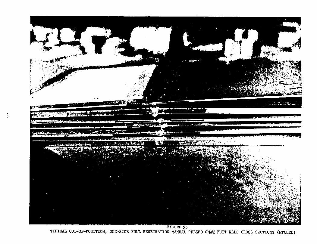
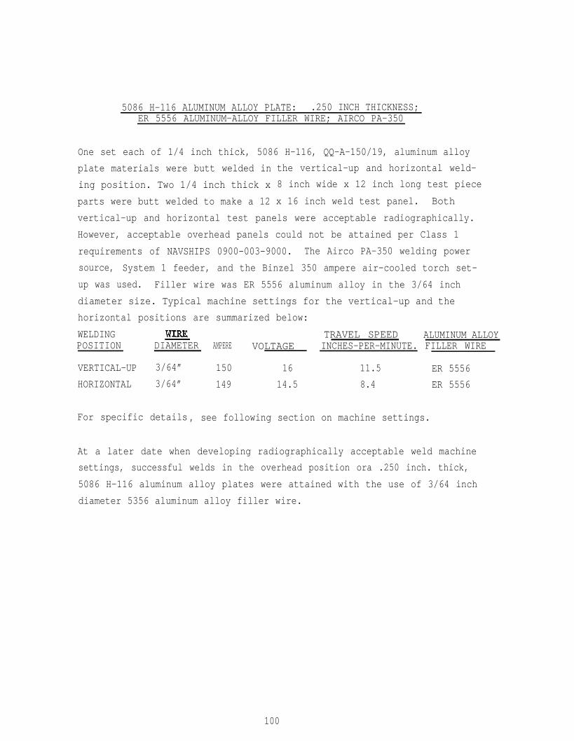
5086 H-116 ALUMINUM ALLOY PLATE: .250 INCH THICKNESS;ER 5556 ALUMINUM-ALLOY FILLER WIRE; AIRCO PA-350
One set each of 1/4 inch thick, 5086 H-116, QQ-A-150/19, aluminum
plate materials were butt welded in
ing position. Two 1/4 inch thick x
parts were butt welded to make a 12
alloy
the vertical-up and horizontal weld-
8 inch wide x 12 inch long test piece
x 16 inch weld test panel. Both
vertical-up and horizontal test panels were acceptable radiographically.
However, acceptable overhead panels could not be attained per Class 1
requirements of NAVSHIPS 0900-003-9000. The Airco PA-350 welding power
source, System 1 feeder, and the Binzel 350 ampere air-cooled torch set-
up was used. Filler wire was ER 5556 aluminum alloy in the 3/64 inch
diameter size. Typical machine settings for the vertical-up and the
horizontal positions are summarized below:
WELDING TRAVEL SPEED ALUMINUM ALLOYPOSITION DIAMETER AMPERE VOLTAGE INCHES-PER-MINUTE. FILLER WIRE
VERTICAL-UP 3/64” 150 16 11.5 ER 5556
HORIZONTAL 3/64” 149 14.5 8.4 ER 5556
For specific details , see following section on machine settings.
At a later date when developing radiographically acceptable weld machine
settings, successful welds in the overhead position ora .250 inch. thick,
5086 H-116 aluminum alloy plates were attained with the use of 3/64 inch
diameter 5356 aluminum alloy filler wire.
100
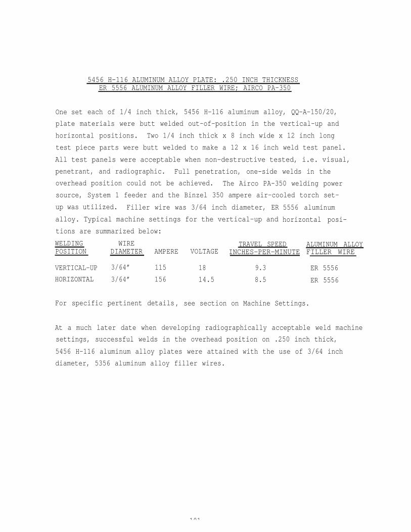
One set
5456 H-116 ALUMINUM ALLOY PLATE: .250 INCH THICKNESSER 5556 ALUMINUM ALLOY FILLER WIRE; AIRCO PA-350
each of 1/4 inch thick, 5456 H-116 aluminum alloy, QQ-A-150/20,
plate materials were butt welded out-of-position in the vertical-up and
horizontal positions. Two 1/4 inch thick x 8 inch wide x 12 inch long
test piece parts were butt welded to make a 12 x 16 inch weld test panel.
All test panels were acceptable when non-destructive tested, i.e. visual,
penetrant, and radiographic. Full penetration, one-side welds in the
overhead position could not be achieved. The Airco PA-350 welding power
source, System 1 feeder and the Binzel 350 ampere air-cooled torch set-
up was utilized. Filler wire was 3/64 inch diameter, ER
alloy. Typical machine settings for the vertical-up and
tions are summarized below:
5556 aluminum
horizontal posi-
WELDING WIRE TRAVEL SPEED ALUMINUM ALLOYPOSITION DIAMETER AMPERE VOLTAGE INCHES-PER-MINUTE FILLER WIRE
VERTICAL-UP 3/64” 115 18 9.3
HORIZONTAL 3/64” 156 14.5 8.5
ER 5556
ER 5556
For specific pertinent details, see section on Machine Settings.
At a much later date when developing radiographically acceptable weld machine
settings, successful welds in the overhead position on .250 inch thick,
5456 H-116 aluminum alloy plates were attained with the use of 3/64 inch
diameter, 5356 aluminum alloy filler wires.
101
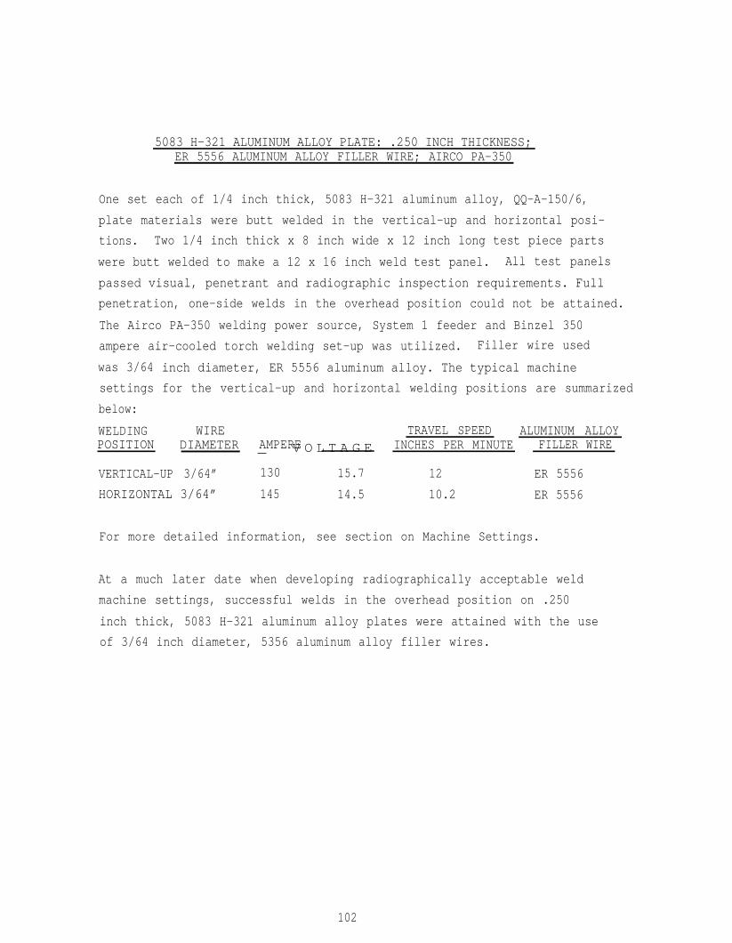
5083 H-321 ALUMINUM ALLOY PLATE: .250 INCH THICKNESS;ER 5556 ALUMINUM ALLOY FILLER WIRE; AIRCO PA-350
One set each of 1/4 inch thick, 5083 H-321 aluminum alloy, QQ-A-150/6,
plate materials were butt welded in the vertical-up and horizontal posi-
tions. Two 1/4 inch thick x 8 inch wide x 12 inch long test piece parts
were butt welded to make a 12 x 16 inch weld test panel. All test panels
passed visual, penetrant and radiographic inspection requirements. Full
penetration, one-side welds in the overhead position could not be attained.
The Airco PA-350 welding power source, System 1 feeder and Binzel 350
ampere air-cooled torch welding set-up was utilized. Filler wire used
was 3/64
settings
below:
WELDINGPOSITION
inch diameter, ER 5556 aluminum alloy. The typical machine
for the vertical-up and horizontal welding positions are summarized
WIRE TRAVEL SPEED ALUMINUM ALLOY DIAMETER AMPERE_ V O L T A G E INCHES PER MINUTE FILLER WIRE
VERTICAL-UP 3/64” 130 15.7 12 ER 5556
HORIZONTAL 3/64” 145 14.5 10.2 ER 5556
For more detailed information, see section on Machine Settings.
At a much later date when developing radiographically acceptable weld
machine settings, successful welds in the overhead position on .250
inch thick, 5083 H-321 aluminum alloy plates were attained with the use
of 3/64 inch diameter, 5356 aluminum alloy filler wires.
102

WELDING PROCEDURE SPECIFICATION QUALIFICATION DATA
Weld procedure qualification test summary pages covering the necessary
welding parameters such as base material, filler wire type and diameters,
shielding gas(es), pulse power source, torch, cup orifice, welding position,
preheat, current characteristics, current range, voltage range, wire feed
speeds, travel speed and non-destructive test results are shown in the
following pages. Specific weld machine settings as well as mechanical
properties data are covered under respective sections in this report.
103
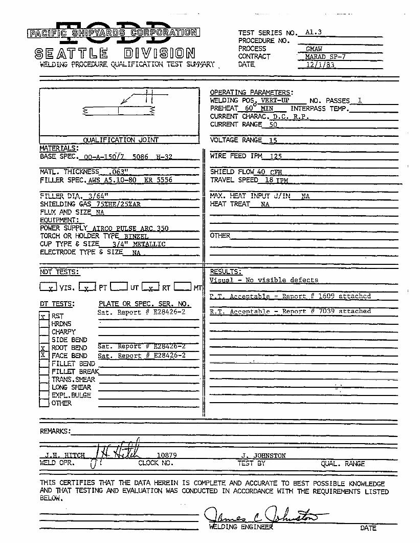
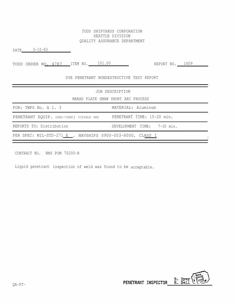
TODD SHIPYARDS CORPORATIONSEATTLE DIVISION
QUALITY ASSURANCE DEPARTMENT
DATE 5-10-83
TODD ORDER NO. 4787 ITEM NO. 101.00
DYE PENETRANT NONDESTRUCTIVE TEST
REPORT NO. 1609
REPORT
JOB DESCRIPTION
MARAD PLATE GMAW SHORT ARC PROCESS
FOR: TWPS No. A 1. 3 MATERIAL: Aluminum
PENETRANT EQUIP. DUBL-CHEK; VISIBLE RED PENETRANT TIME: 15-20 min.
REPORTS TO: Distribution DEVELOPMENT TIME: 7-30 min.
PER SPEC: MIL-STD-271 E , NAVSHIPS 0900-003-8000, CLASS II
CONTRACT NO. NNS POM 70200-R
Liquid
QA-PT-
penetrant inspection of weld was found to be acceptable.
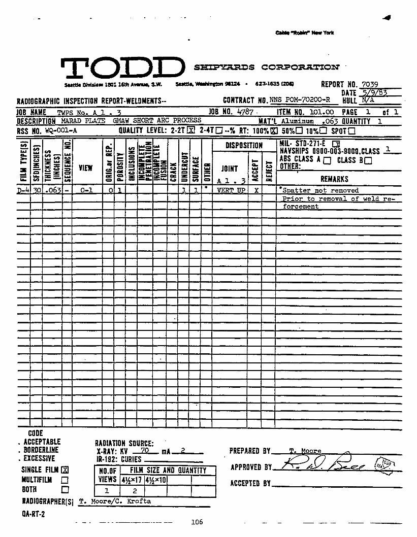


TODD SHIPYARDS CORPORATIONSEATTLE DIVISION
QUALITY ASSURANCE DEPARTMENT
DATE 5-10-83
TODD ORDER NO. 4787 ITEM NO. 101.00 REPORT NO. 1611
DYE PENETRANT NONDESTRUCTIVE TEST REPORT
JOB DESCRIPTION
MARAD PLATE GMAW SHORT ARC PROCESS
FOR: TWPS NO. A 1 . 23 MATERIAL: Aluminum
PENETRANT EQUIP. DUBL-CHEK; VISIBLE RED PENETRANT TIME: 15-20-.
REPORTS TO: Distribution DEVELOPMENT TIME: 7-30 min.
PER SPEC: MIL-STD-271 E , NAVSHIPS 0900-003-8000, CLASS I
CONTRACT NO. NNS FOM 70200-R
Liquid penetrant inspection
QA-PT.
of weld was found to be acceptable.
108
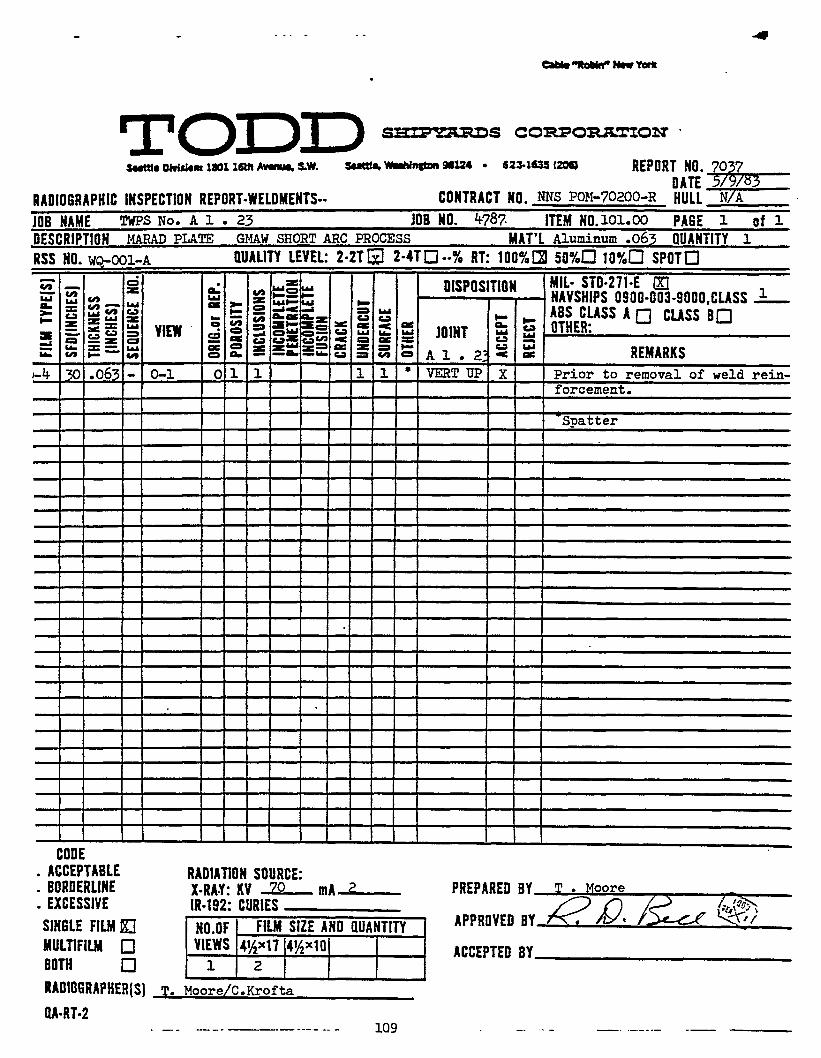
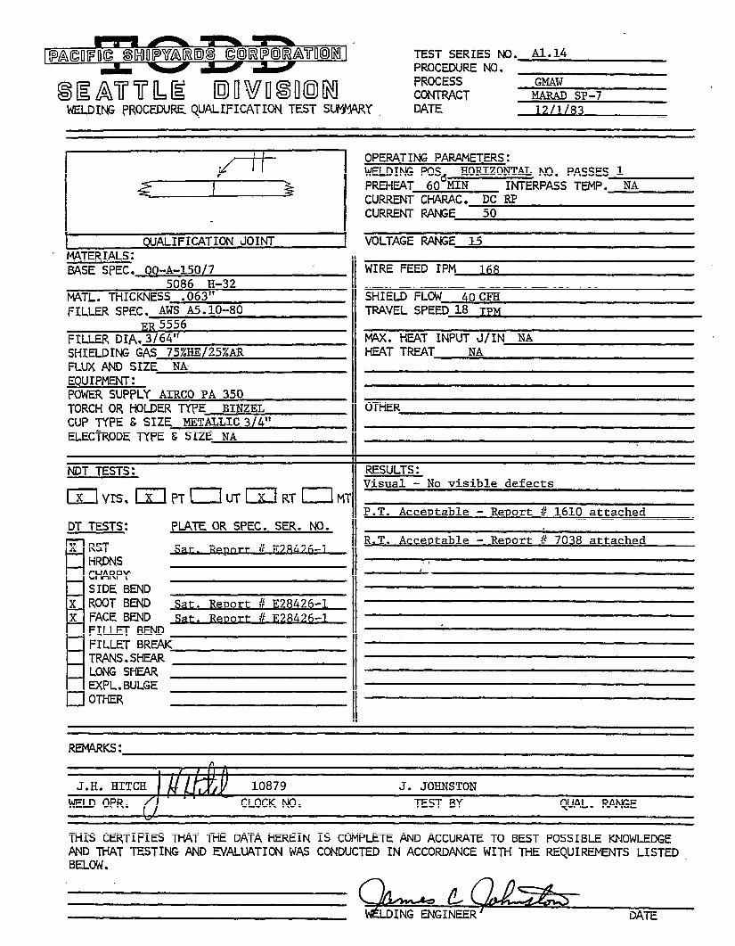
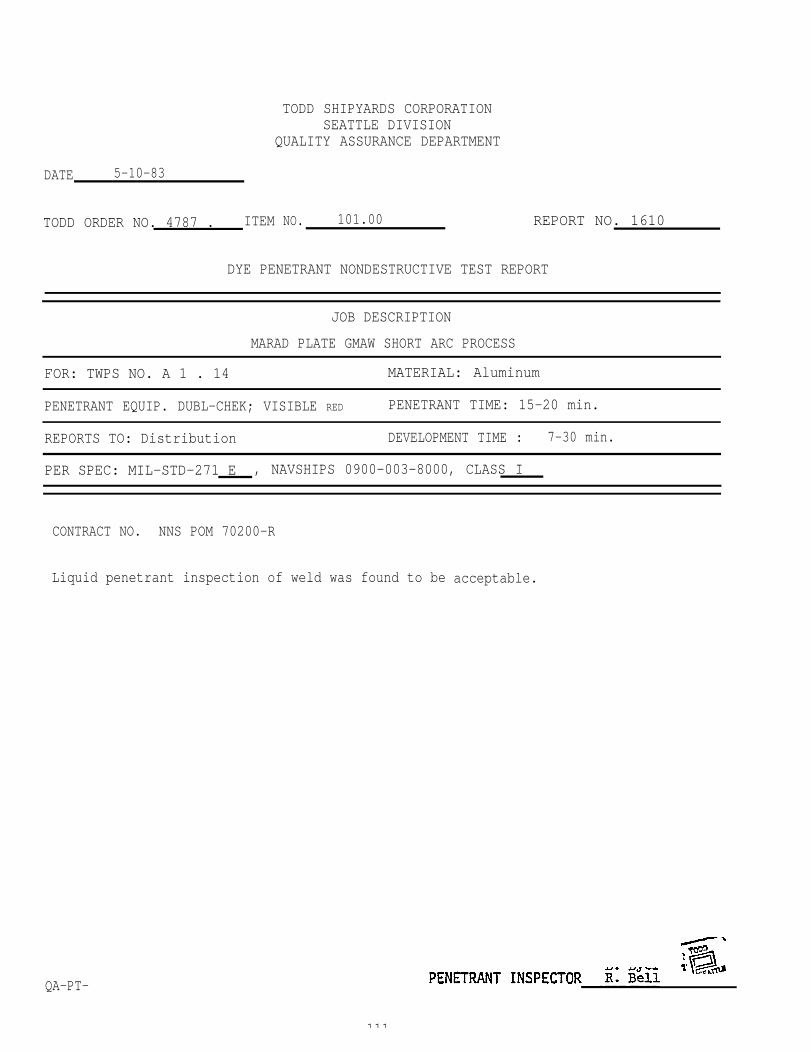
TODD SHIPYARDS CORPORATIONSEATTLE DIVISION
QUALITY ASSURANCE DEPARTMENT
DATE 5-10-83
TODD ORDER NO. 4787 . ITEM NO. 101.00
DYE PENETRANT NONDESTRUCTIVE TEST REPORT
REPORT NO. 1610
JOB DESCRIPTION
MARAD PLATE GMAW SHORT ARC PROCESS
FOR: TWPS NO. A 1 . 14 MATERIAL: Aluminum
PENETRANT EQUIP. DUBL-CHEK; VISIBLE RED PENETRANT TIME: 15-20 min.
REPORTS TO: Distribution DEVELOPMENT TIME : 7-30 min.
PER SPEC: MIL-STD-271 E , NAVSHIPS 0900-003-8000, CLASS I
CONTRACT NO. NNS POM 70200-R
Liquid penetrant inspection of weld was found to be acceptable.
QA-PT-
111
TODD SHIPYARDS CORPORATIONSEATTLE DIVISION
QUALITY ASSURANCE DEPARTMENT
DATE 5-10-83
TODD ORDER NO. 4787 . ITEM NO. 101.00 REPORT NO. 1612
DYE PENETRANT NONDESTRUCTIVE TEST REPORT
JOB DESCRIPTION
MARAD PLATE GMAW SHORT ARC PROCESS
FOR: TWPS No. A 2.5 MATERIAL: Aluminum
PENERANT EQUIP. DUBL-CHEK; VISIBLE RED PENETRANT TIME: 15-20 min.
REPORTS TO: Distribution DEVELOPMENT TIME : 7-30 min.
PER SPEC: MIL-STD-271 E , NAVSHIPS 0900-003-8000, CLASS I
CONTRACT NO. NNS POM 70200-R
Liquid penetrant inspection of weld was found to be acceptable.
QA-PT-
114
TODD SHIPYARDS CORPORATIONSEATTLE DIVISION
QUALITY ASSURANCE DEPARTMENT
DATE 5-10-83
TODD ORDER NO. 4787 . ITEM No. 101.00 REPORT NO. 1613
DYE PENETRANT NONDESTRUCTIVE TEST REPORT
JOB DESCRIPTION
MARAD PLATE GMAW SHORT ARC PROCESS
FOR: TWPS No. B 1 . 18 MATERIAL: Aluminum
PENETRANT EQUIP. DUBL-CHEK; VISIBLE RED PENETRANT TIME: 15-20 min.
REPORTS TO: Distribution DEVELOPMENT TIME : 7-30 min.
PER SPEC: MI L-STD-271 E , NAVSHIPS 0900-003-8000, CLASS I
CONTRACT NO. NNS POM 70200-R
Liquid penetrant inspection of weld was found to be acceptable.
QA-PT- PENETRANT INSPECTOR R. Bell ..-
117
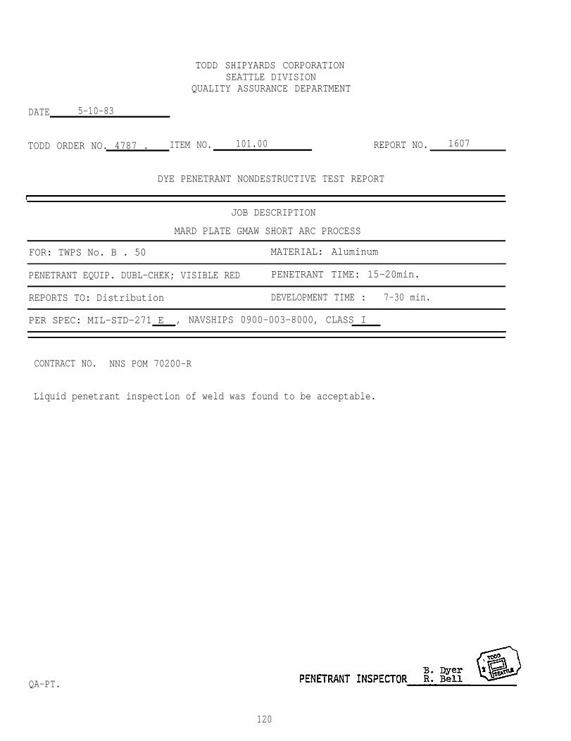
TODD SHIPYARDS CORPORATIONSEATTLE DIVISION
QUALITY ASSURANCE DEPARTMENT
DATE 5-10-83
TODD ORDER NO. 4787 . ITEM NO. 101.00 REPORT NO. 1607
DYE PENETRANT NONDESTRUCTIVE TEST REPORT
JOB DESCRIPTION
MARD PLATE GMAW SHORT ARC PROCESS
FOR: TWPS No. B . 50 MATERIAL: Aluminum
PENETRANT EQUIP. DUBL-CHEK; VISIBLE RED PENETRANT TIME: 15-20min.
REPORTS TO: Distribution DEVELOPMENT TIME : 7-30 min.
PER SPEC: MIL-STD-271 E , NAVSHIPS 0900-003-8000, CLASS I
CONTRACT NO. NNS POM 70200-R
Liquid
QA-PT.
penetrant inspection of weld was found to be acceptable.
120
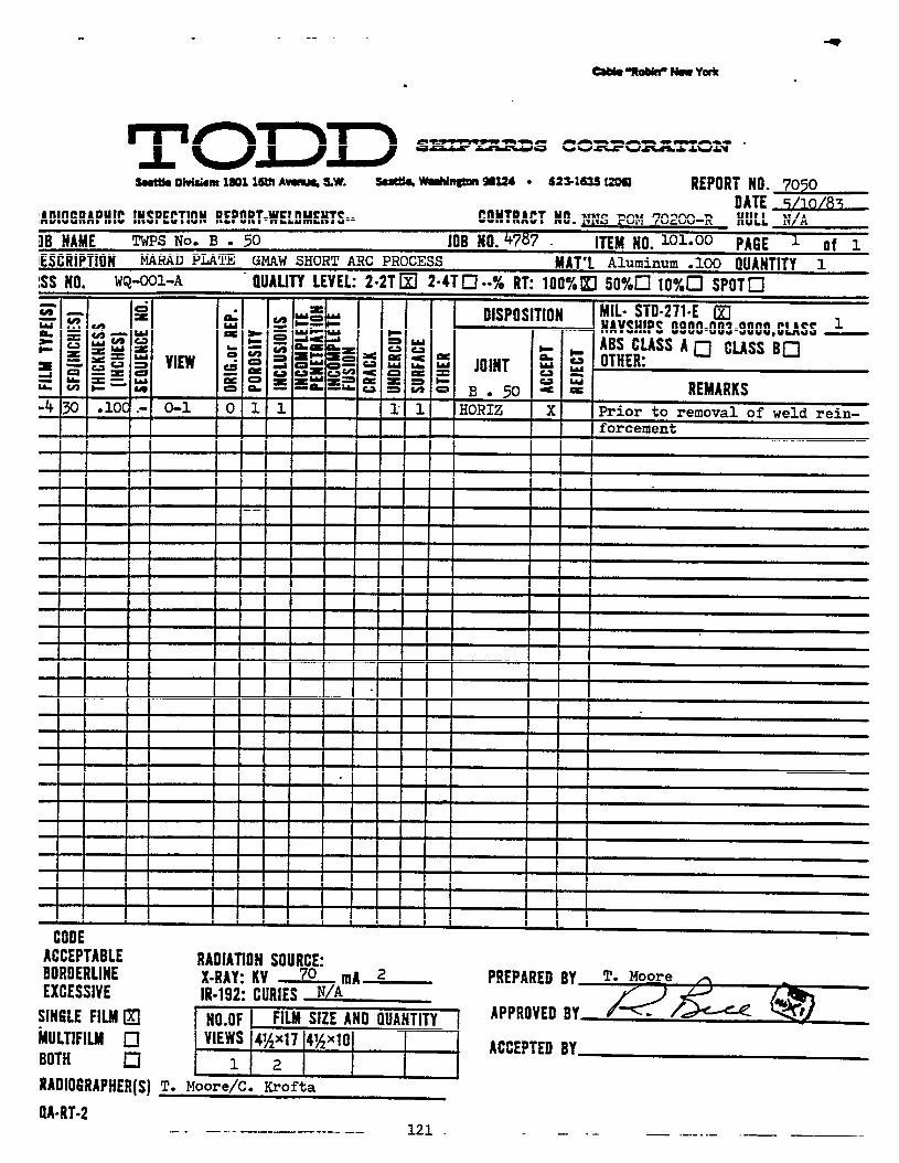
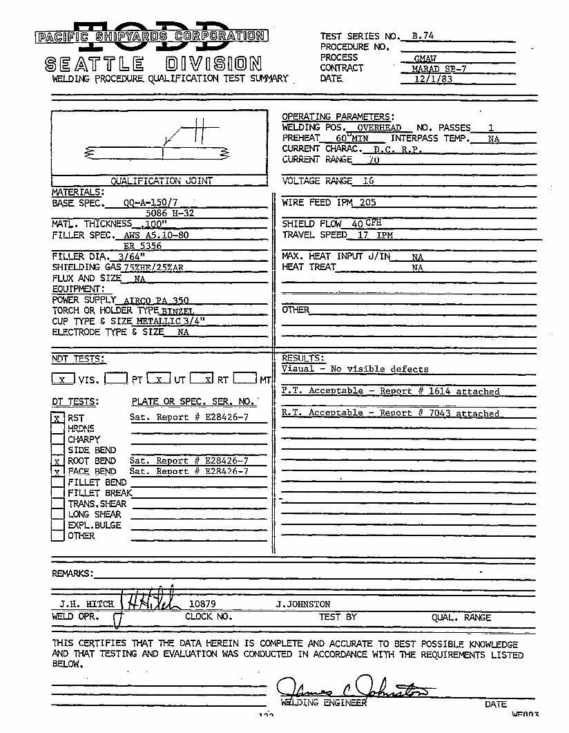
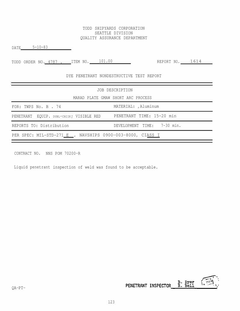
TODD SHIPYARDS CORPORATIONSEATTLE DIVISION
QUALITY ASSURANCE DEPARTMENT
DATE 5-10-83
TODD ORDER NO. 4787 . ITEM NO. 101.00 REPORT
DYE PENETRANT NONDESTRUCTIVE TEST REPORT
NO. 1614
I
JOB DESCRIPTION
MARAD PLATE GMAW SHORT ARC PROCESS
FOR: TWPS No. B . 74 MATERIAL: ,Aluminum
PENETRANT EQUIP. DUBL-CHIIK; VISIBLE RED PENETRANT TIME: 15-20 min
REPORTS TO: Distribution DEVELOPMENT TIME: 7-30 min.
PER SPEC: MIL-STD-271 E , NAVSHIPS 0900-003-8000, CIASS I
CONTRACT NO. NNS POM 70200-R
Liquid
QA-PT-
penetrant inspection of weld was found to be acceptable.
123
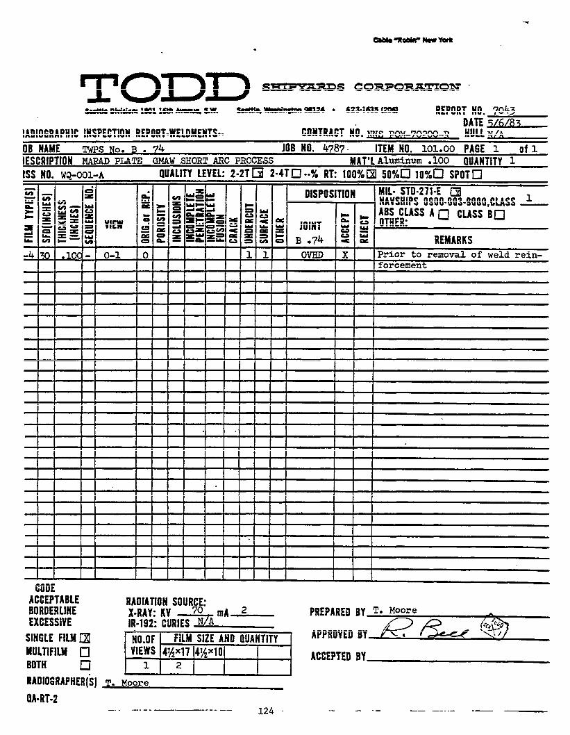

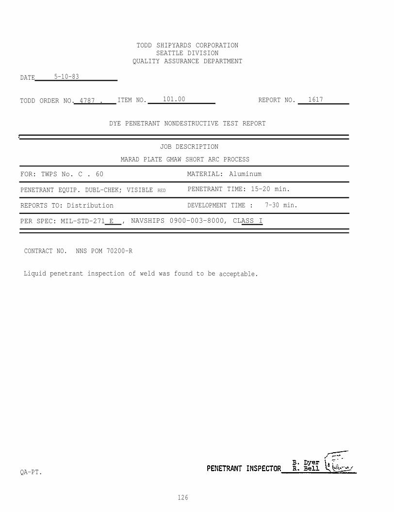
TODD SHIPYARDS CORPORATIONSEATTLE DIVISION
QUALITY ASSURANCE DEPARTMENT
DATE 5-10-83
TODD ORDER NO. 4787 . ITEM NO. 101.00 REPORT NO. 1617
DYE PENETRANT NONDESTRUCTIVE TEST REPORT
JOB DESCRIPTION
MARAD PLATE GMAW SHORT ARC PROCESS
FOR: TWPS No. C . 60 MATERIAL: Aluminum
PENETRANT EQUIP. DUBL-CHEK; VISIBLE RED PENETRANT TIME: 15-20 min.
REPORTS TO: Distribution DEVELOPMENT TIME : 7-30 min.
PER SPEC: MIL-STD-271 E , NAVSHIPS 0900-003-8000, CLASS I
CONTRACT NO. NNS POM 70200-R
Liquid penetrant inspection of weld was found to be acceptable.
QA-PT.
126
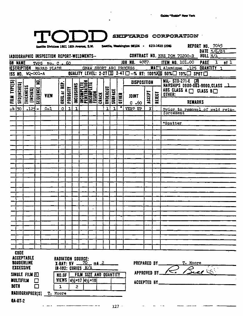
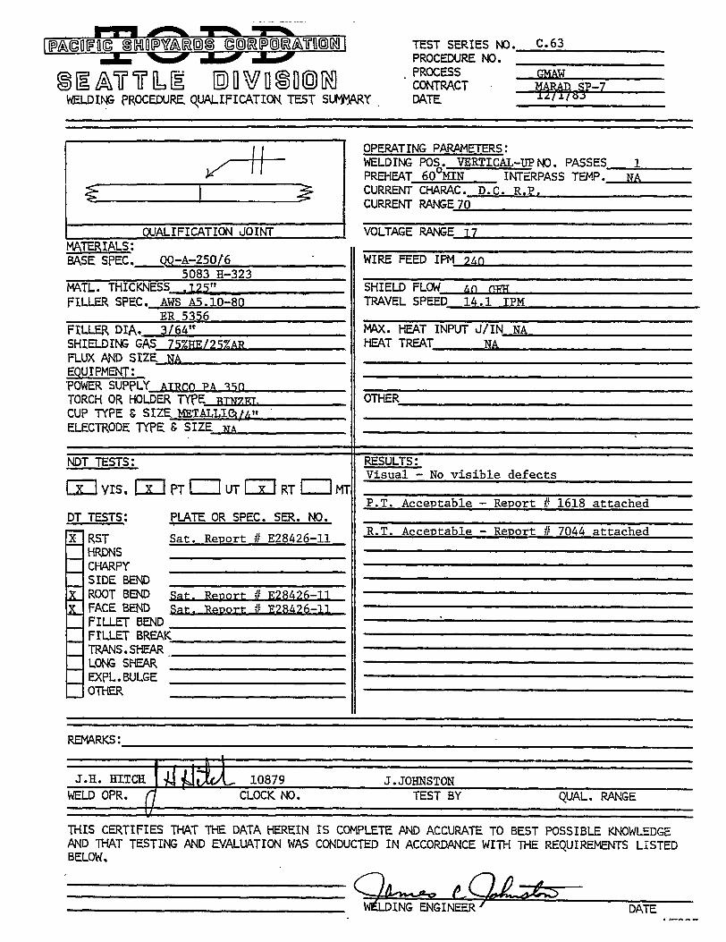
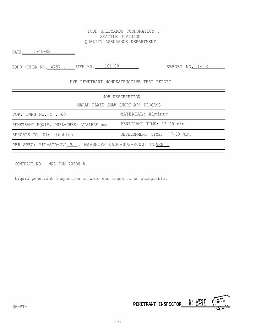
TODD SHIPYARDS CORPORATION .SEATTLE DIVISION
QUALITY ASSURANCE DEPARTMENT
DATE 5-10-83
TODD ORDER NO. 4787 . ITEM NO. 101.00 REPORT NO. 1618
DYE PENETRANT NONDESTRUCTIVE TEST REPORT
JOB DESCRIPTION
MARAD PLATE GMAW SHORT ARC PROCESS
FOR: TWPS No. C . 63 MATERIAL: Alminum
PENETRANT EQUIP. DUBL-CHEK; VISIBLE RED PENETRANT TIME: 15-20 min.
REPORTS TO: Distribution DEVELOPMENT TIME: 7-30 min.
PER SPEC: MIL-STD-271 E , NAVSHIPS 0900-003-8000, CLASS I
CONTRACT NO. NNS POM 70200-R
Liquid penetrant
QA-PT-
inspection of weld was found to be acceptable.
129
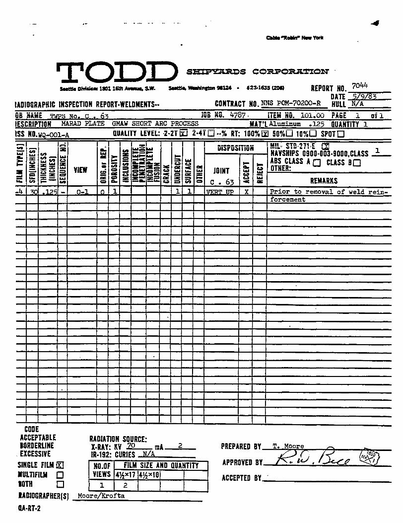
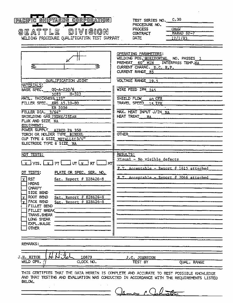
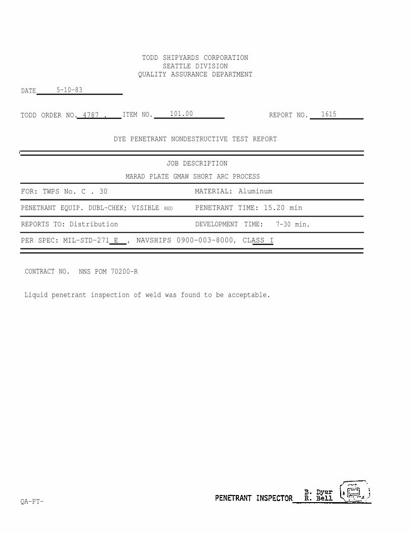
TODD SHIPYARDS CORPORATIONSEATTLE DIVISION
QUALITY ASSURANCE DEPARTMENT
DATE 5-10-83
TODD ORDER NO. 4787 . ITEM NO. 101.00
DYE PENETRANT NONDESTRUCTIVE TEST REPORT
REPORT NO. 1615
JOB DESCRIPTION
MARAD PLATE GMAW SHORT ARC PROCESS
FOR: TWPS No. C . 30 MATERIAL: Aluminum
PENETRANT EQUIP. DUBL-CHEK; VISIBLE RED PENETRANT TIME: 15.20 min
REPORTS TO: Distribution DEVELOPMENT TIME: 7-30 min.
PER SPEC: MIL-STD-271 E , NAVSHIPS 0900-003-8000, CLASS I
CONTRACT NO. NNS POM 70200-R
Liquid penetrant inspection of weld was found to be acceptable.
QA-PT-

TODD SHIPYARDS CORPORATIONSEATTLE DIVISION
QUALITY ASSURANCE DEPARTMENT
DATE 5-10-83
TODD ORDER NO. 4787 . ITEM NO. 101.00
DYE PENETRANT NONDESTRUCTIVE TEST REPORT
REPORT NO. 1616
JOB DESCRIPTION
MARAD PLATE GMAW SHORT ARC PROCESS
FOR: TWPS. C. 46 MATERIAL: Aluminum
PENETRANT EQUIP. DUBL-CHEK; VISIBLE RED PENETRANT TIME: 15-20min.
REPORTS TO: Distribution DEVELOPMENT TIME : 7-30 min.
PER SPEC: MIL-STD-271 E , NAVSHIPS 0900-003-8000, CLASS I
CONTRACT NO. NNS POM 70200-R
Liquid penetrant inspection of weld was found to be acceptable.
QA-PT-
135
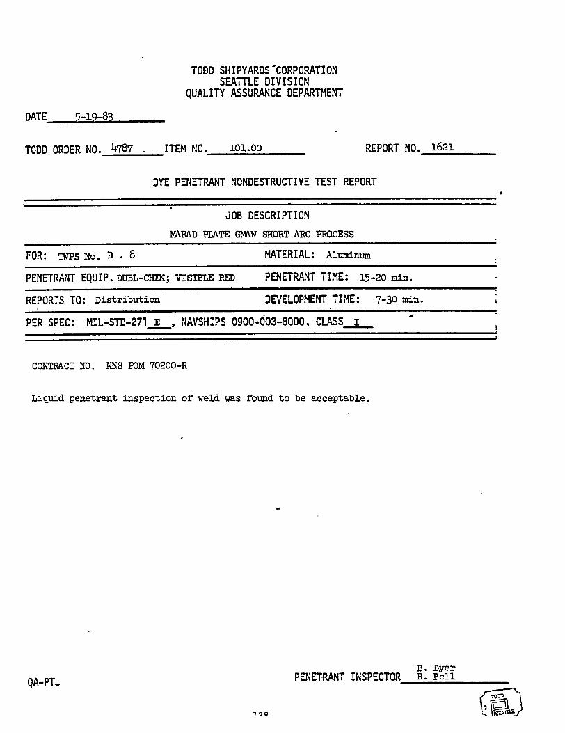
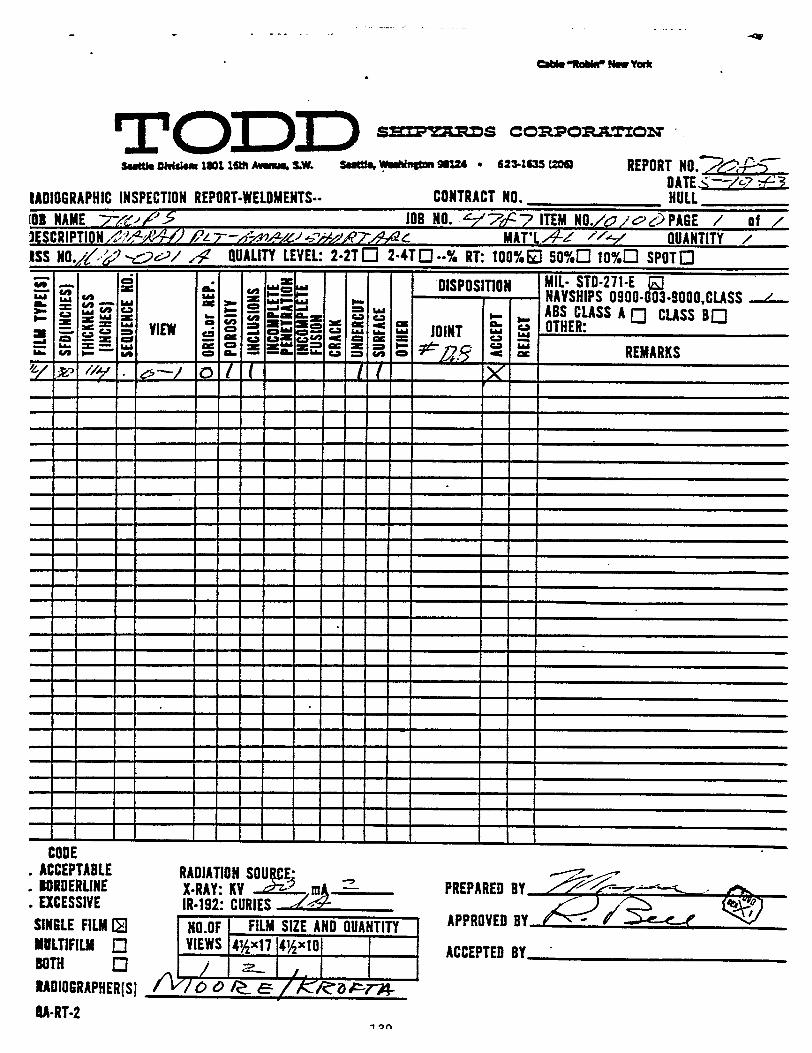
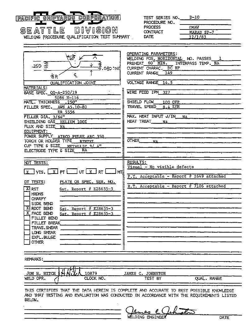
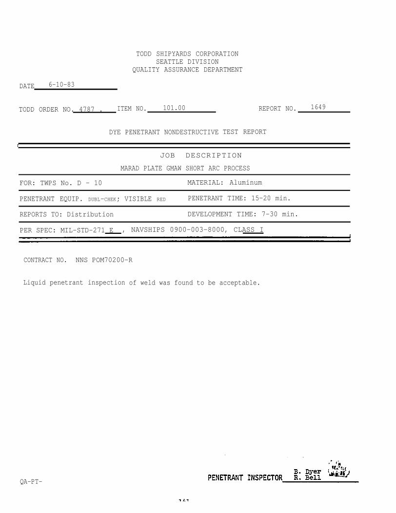
TODD SHIPYARDS CORPORATIONSEATTLE DIVISION
QUALITY ASSURANCE DEPARTMENT
DATE 6-10-83
TODD ORDER NO. 4787 . ITEM NO. 101.00
DYE PENETRANT NONDESTRUCTIVE
REPORT NO. 1649
TEST REPORT
JOB DESCRIPTION
MARAD PLATE GMAW SHORT ARC PROCESS
FOR: TWPS No. D - 10 MATERIAL: Aluminum
PENETRANT EQUIP. DUBL-CHEK; VISIBLE RED PENETRANT TIME: 15-20 min.
REPORTS TO: Distribution DEVELOPMENT TIME: 7-30 min.
PER SPEC: MIL-STD-271 E , NAVSHIPS 0900-003-8000, CLASS I
CONTRACT NO. NNS POM70200-R
Liquid penetrant inspection
QA-PT-
of weld was found to be acceptable.
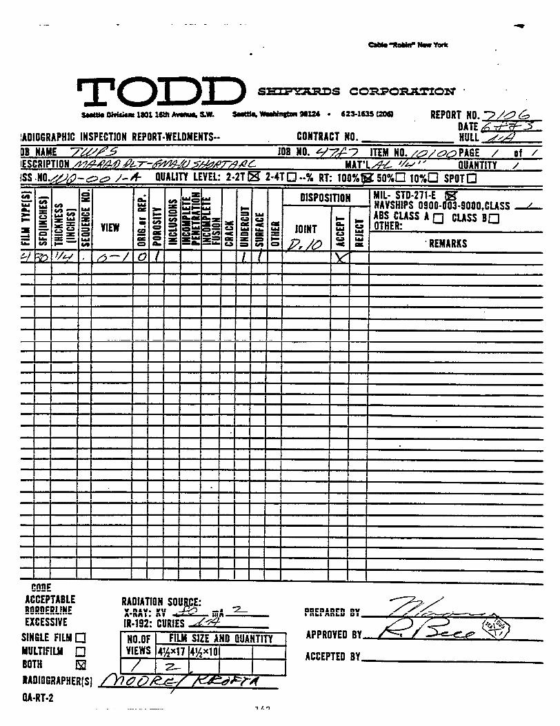

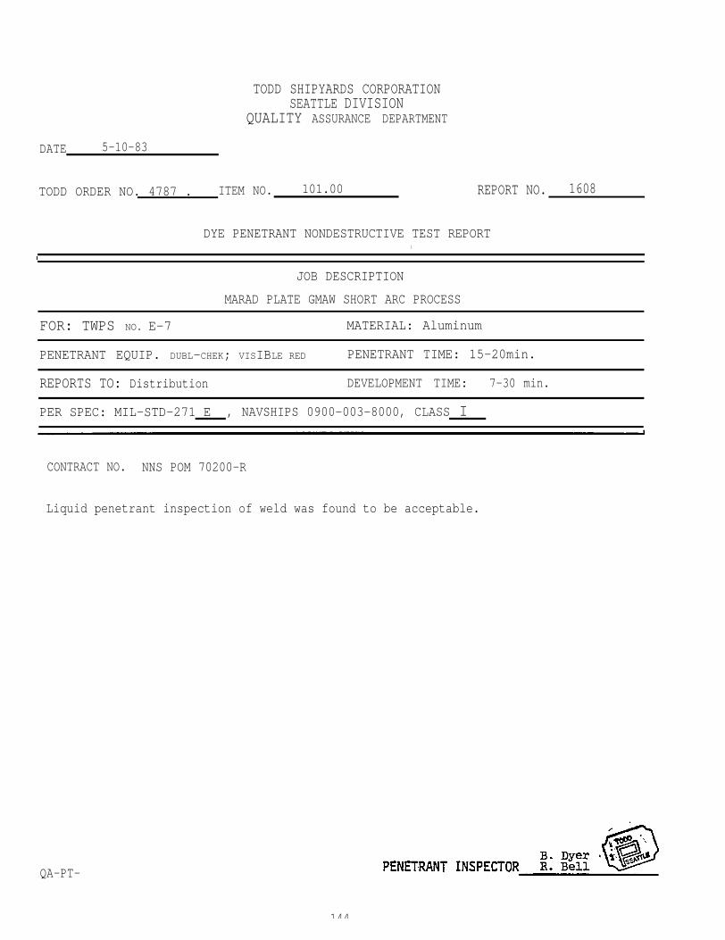
TODD SHIPYARDS CORPORATIONSEATTLE DIVISION
QUALITY ASSURANCE DEPARTMENT
DATE 5-10-83
TODD ORDER NO. 4787 . ITEM NO. 101.00
DYE PENETRANT NONDESTRUCTIVE TEST REPORTl
REPORT NO. 1608
JOB DESCRIPTION
MARAD PLATE GMAW SHORT ARC PROCESS
FOR: TWPS NO. E-7 MATERIAL: Aluminum
PENETRANT EQUIP. DUBL-CHEK; VISIBLE RED PENETRANT TIME: 15-20min.
REPORTS TO: Distribution DEVELOPMENT TIME: 7-30 min.
PER SPEC: MIL-STD-271 E , NAVSHIPS 0900-003-8000, CLASS I
CONTRACT NO. NNS POM 70200-R
Liquid penetrant inspection of weld was found to be acceptable.
QA-PT-
144
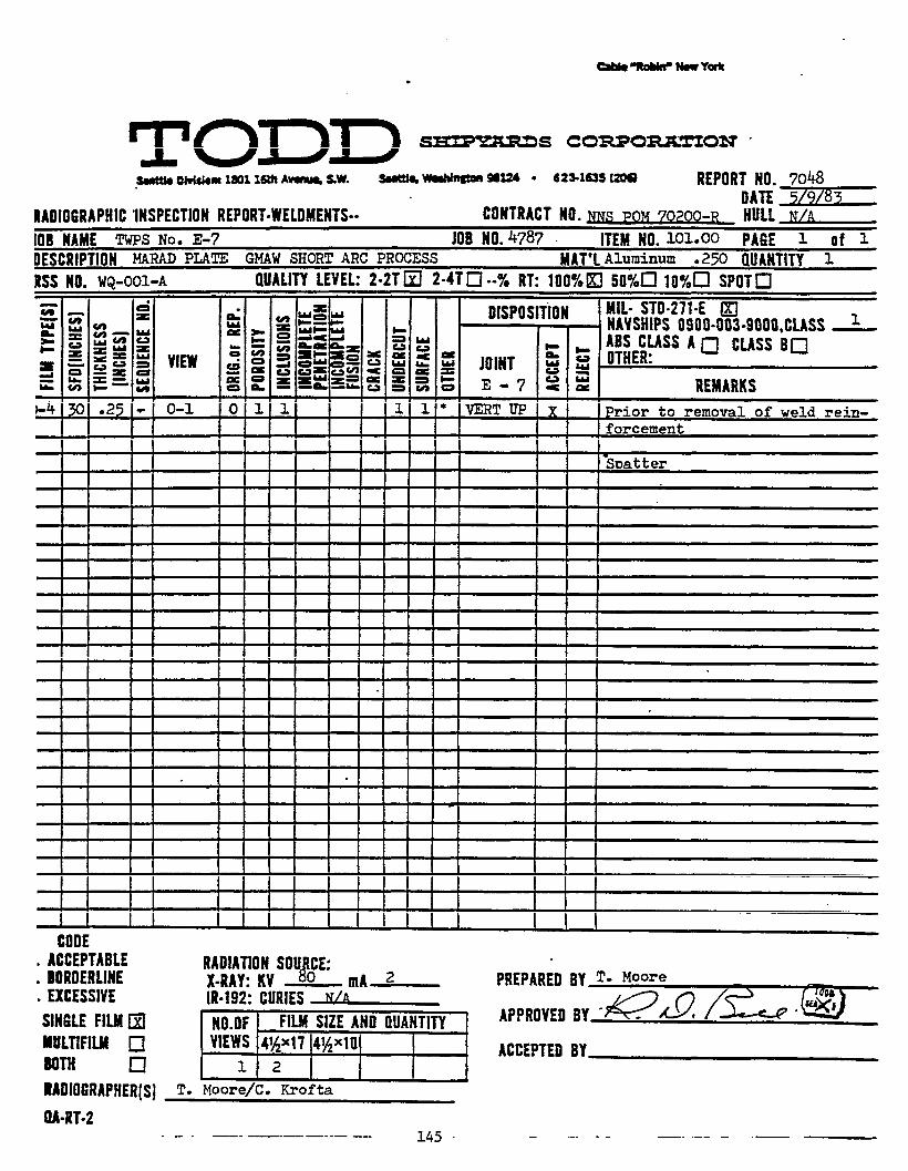
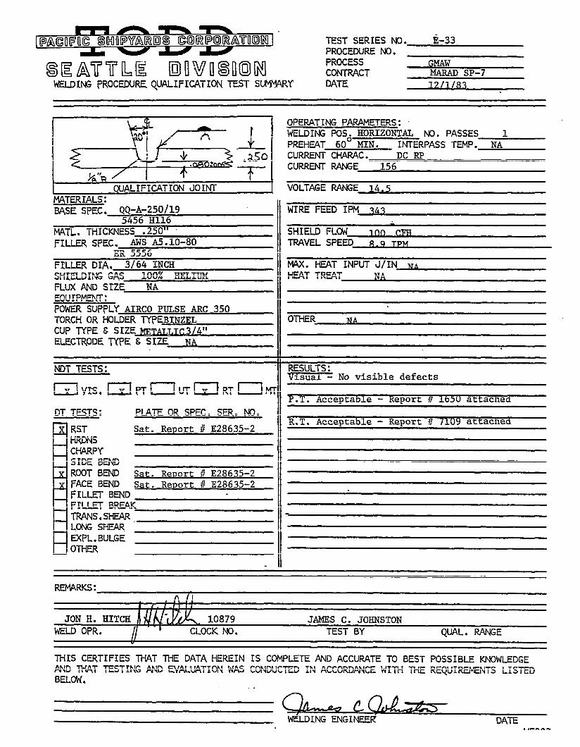

TODD SHIPYARDS CORPORATIONSEATTLE DIVISION
QUALTY ASSURANCE DEPARTMENT
DATE 6-10-83
TODD ORDER NO. 4787 . ITEM NO. 101.00
DYE PENETRANT NONDESTRUCTIVE TEST REPORT
REPORT NO. 1650
JOB DESCRIPTION
MARAD PLATE GMAW SHORT ARC PROCESS
FOR: TWPS NO. E -33 MATERIAL: AIuminum
PENETRANT EQUIP. DUBL-CHEK; ,VISIBLE RED PENETRANT TIME: 15-20 min.
REPORTS TO: Distribution DEVELOPMENT TIME: 7-30 min.
PER SPEC: MIL-STD-271 E , NAVSHIPS 0900-003-8000, CLASS I
CONTRACT NO. NNS POM 70200-R
Liquid
QA-PT
penetrant inspection of weld was found to.be acceptable.
147
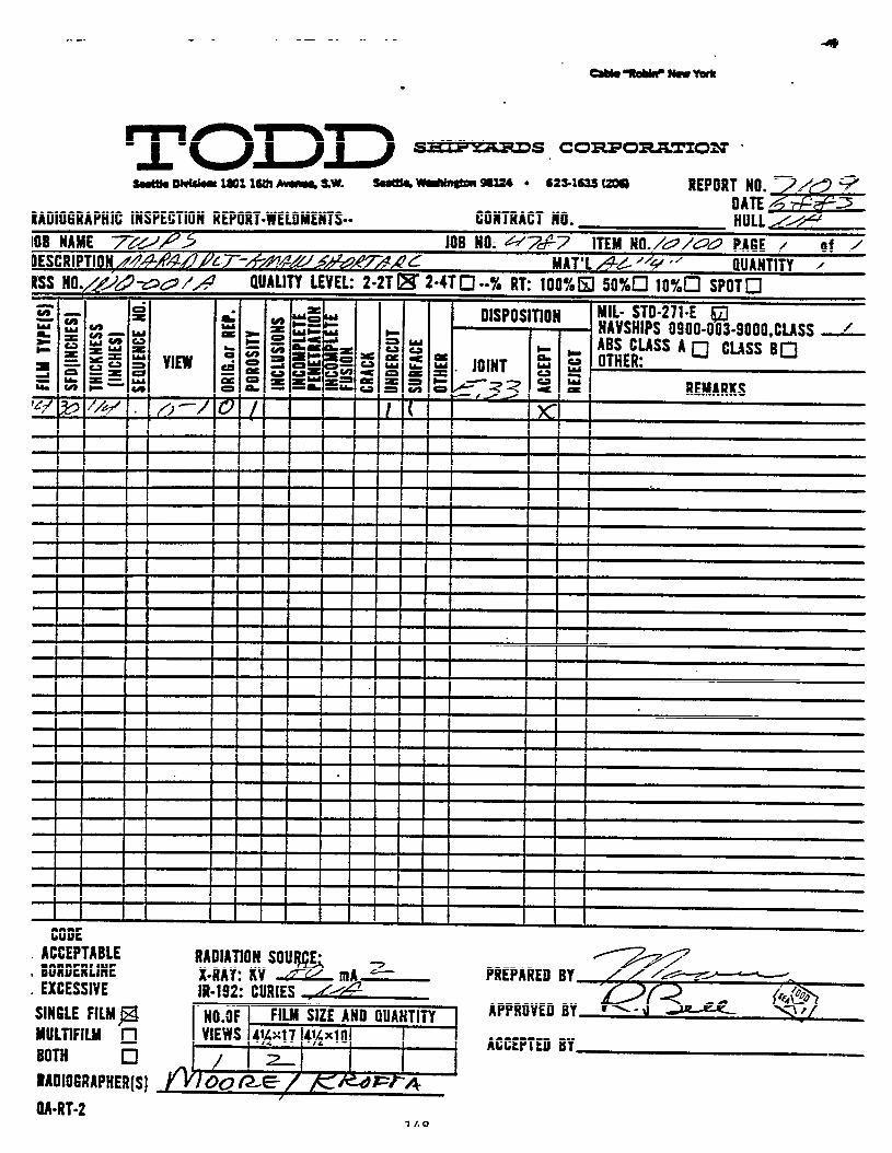
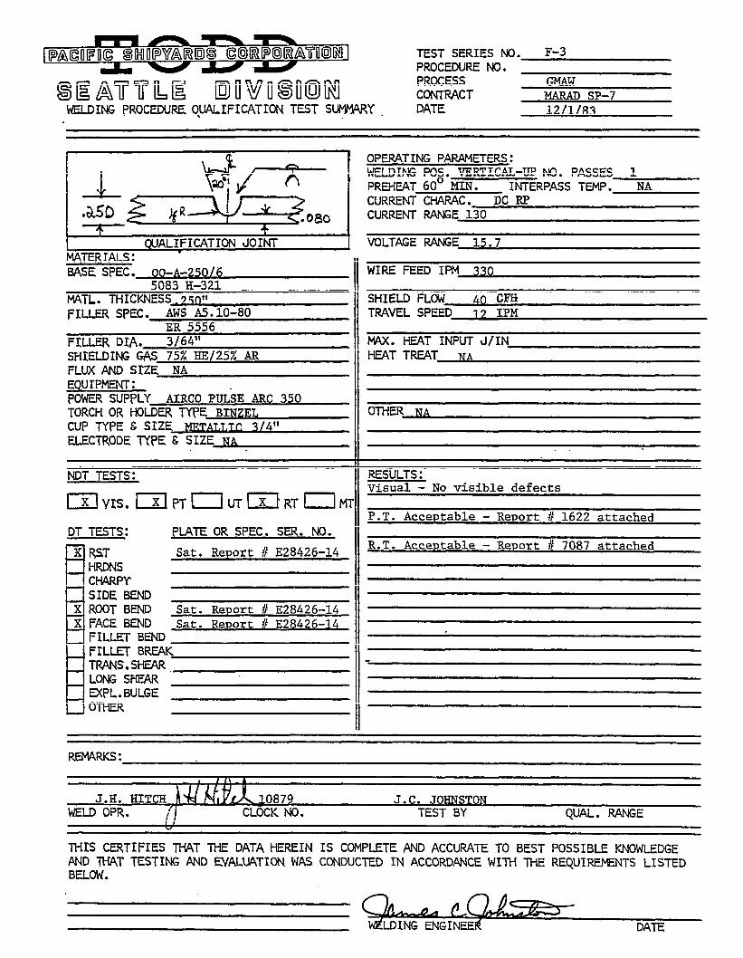

TODD SHIPYARDS CORPORATIONSEATTLE DIVISION
QUALITY ASSURANCE DEPARTMENT
DATE 5-19-83
TODD ORDER NO. 4787 ITEM NO. 101.00
DYE PENETRANT NONDESTRUCTIVE TEST REPORT
REPORT NO. 1622
JOB DESCRIPTION
MARAD PLATE GMAW SHORT ARC PROCESS
FOR: TWPS No. F . 3 MATERIAL: Aluminum
PENETRANT EQUIP. DUBL-CHEK; VISIBLE RED PENETRANT TIME: 15-20 min.
REPORTS TO: Distribution DEVELOPMENT TIME: 7-30 min.
PER SPEC: MIL-STD-271 E , NAVSHIPS 0900-003-8000, CLASS I
CONTRACT NO. NNW POM 70200-R
Liquid penetrant inspection of weld was found to be acceptable.
QA-PT-
150
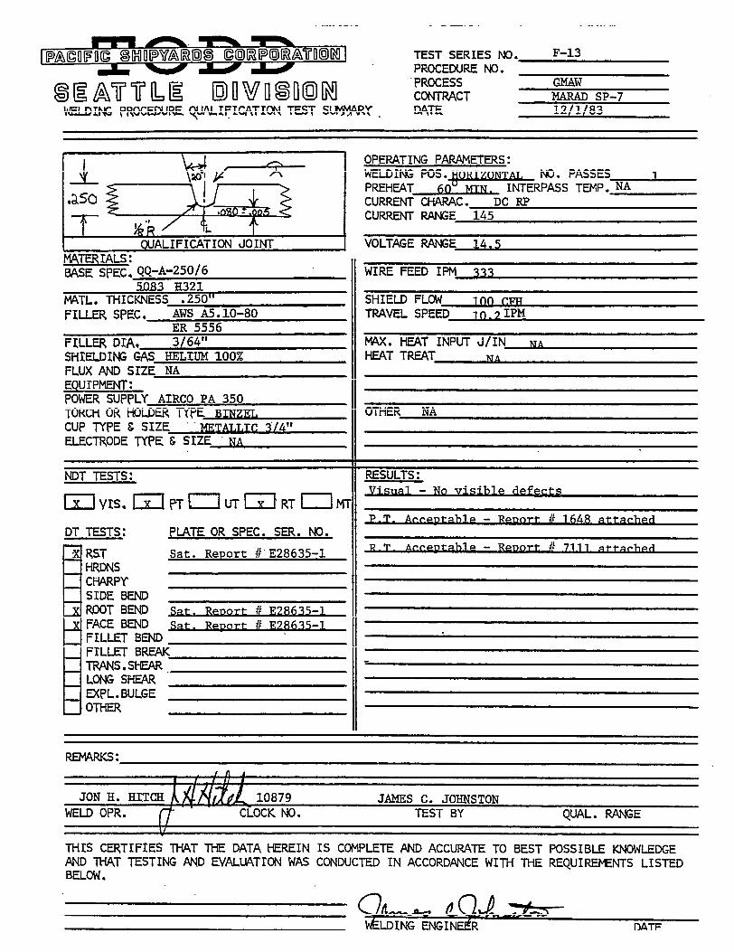
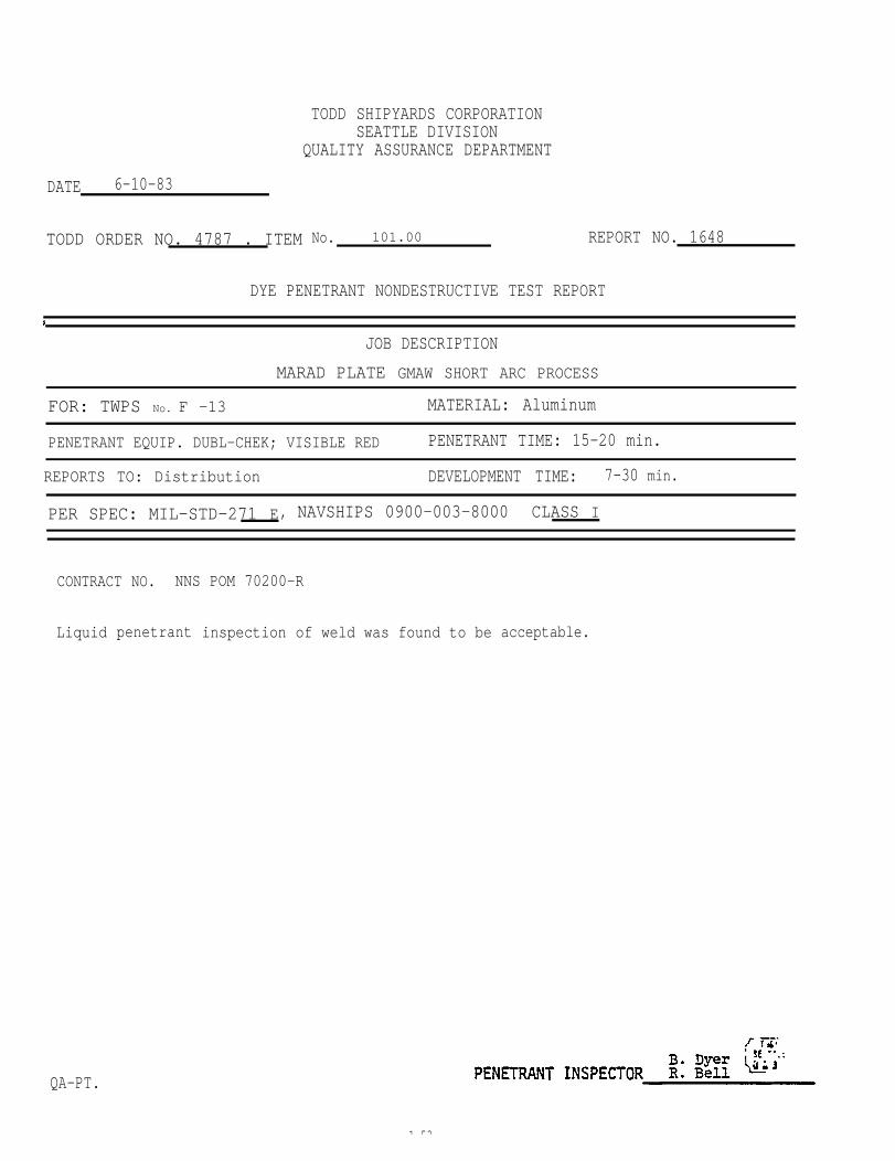
DATE 6-10-83
TODD ORDER NO. 4787 . ITEM
TODD SHIPYARDS CORPORATIONSEATTLE DIVISION
QUALITY ASSURANCE DEPARTMENT
No. 101.00 REPORT NO. 1648
DYE PENETRANT NONDESTRUCTIVE TEST REPORT
)
JOB DESCRIPTION
MARAD PLATE GMAW SHORT ARC PROCESS
FOR: TWPS No. F -13 MATERIAL: Aluminum
PENETRANT EQUIP. DUBL-CHEK; VISIBLE RED PENETRANT TIME: 15-20 min.
REPORTS TO: Distribution DEVELOPMENT TIME: 7-30 min.
PER SPEC: MIL-STD-271 E, NAVSHIPS 0900-003-8000 CLASS I
CONTRACT NO. NNS POM 70200-R
Liquid
QA-PT.
penetrant inspection of weld was found to be acceptable.
1 53
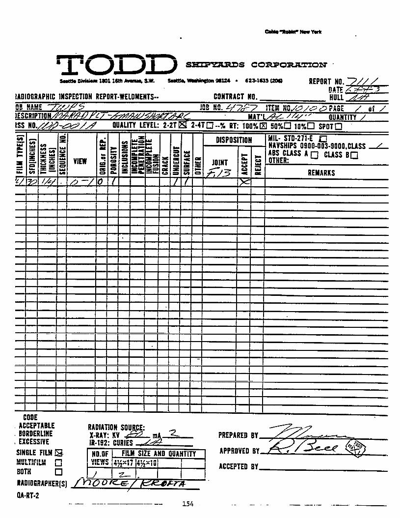
MECHANIZED PULSE ARC WELDING :FLAT POSITION
5083 H-321 ALUMINUM ALLOY PLATE: .500 INCH THICKNESSER 5356 ALUMINUM ALLOY FILLER WIRE; MILLER PULSTAR 450
Mechanized flat position, one-side, full penetration gas metal arc
butt welding of .500 inch thick 5083 H-321, QQ-A-250/6 was accomplished
with the use of a “BUG-O” tractor, Model 2000, with a post-mounted
Airco AH 35-C2 water cooled torch. An Airco AHF-NP feeder was used
in conjunction with a Miller Pulstar 450. The welding filler wire
was 3/64 inch diameter 5356 aluminum alloy. Shielding gas used was 75%
helium/25% argon. Acceptable non-destructive test results and mechanical
properties data were attained. Weld procedure qualification data and
specific welding machine settings are reported in their respective
sections. A typical mechanized pulse arc welding set-up for flat po-
sition welding is illustrated in Figure 56. A mechanized pulse arc
welding of test panel is shown in Figure 57. A mechanized pulse arc
welding root bead in .500 inch thick 5083 H-321 aluminum alloy plates
is illustrated in Figure 58. Weld bead surfaces and also under-beads
are shown
A limited
materials
pulse gas
in Figures 59 and 60.
number of .063 to .250 inch thick 5000 series aluminum alloy
were butt welded into test panels with the use of mechanized
metal arc welding in the flat position. These panels were
subsequently non-destructively inspected per the penetrant and
radiographic test requirements exclusively, i.e. without destructive
testing for mechanical properties. Acceptable machine settings
which were established with the use of other pulse GMAW welding power
sources and accessories are covered in the following section entitled
“Pulse Arc Weld Machine Settings”.
155

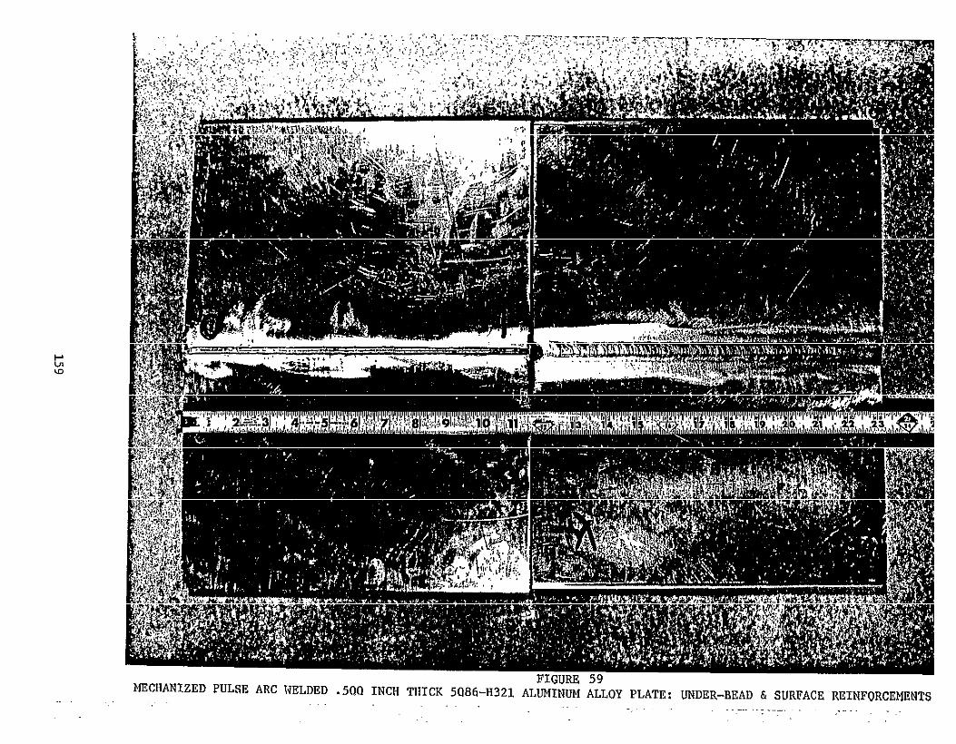
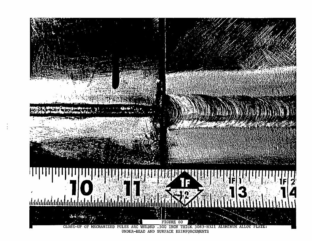
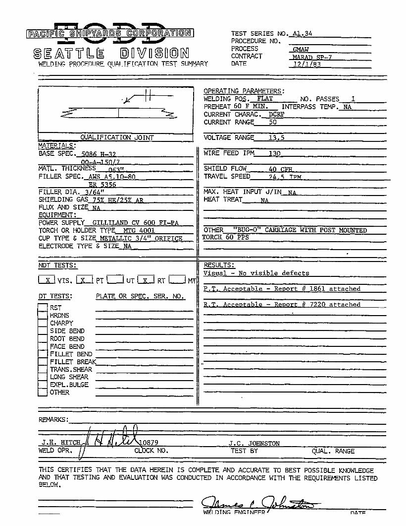
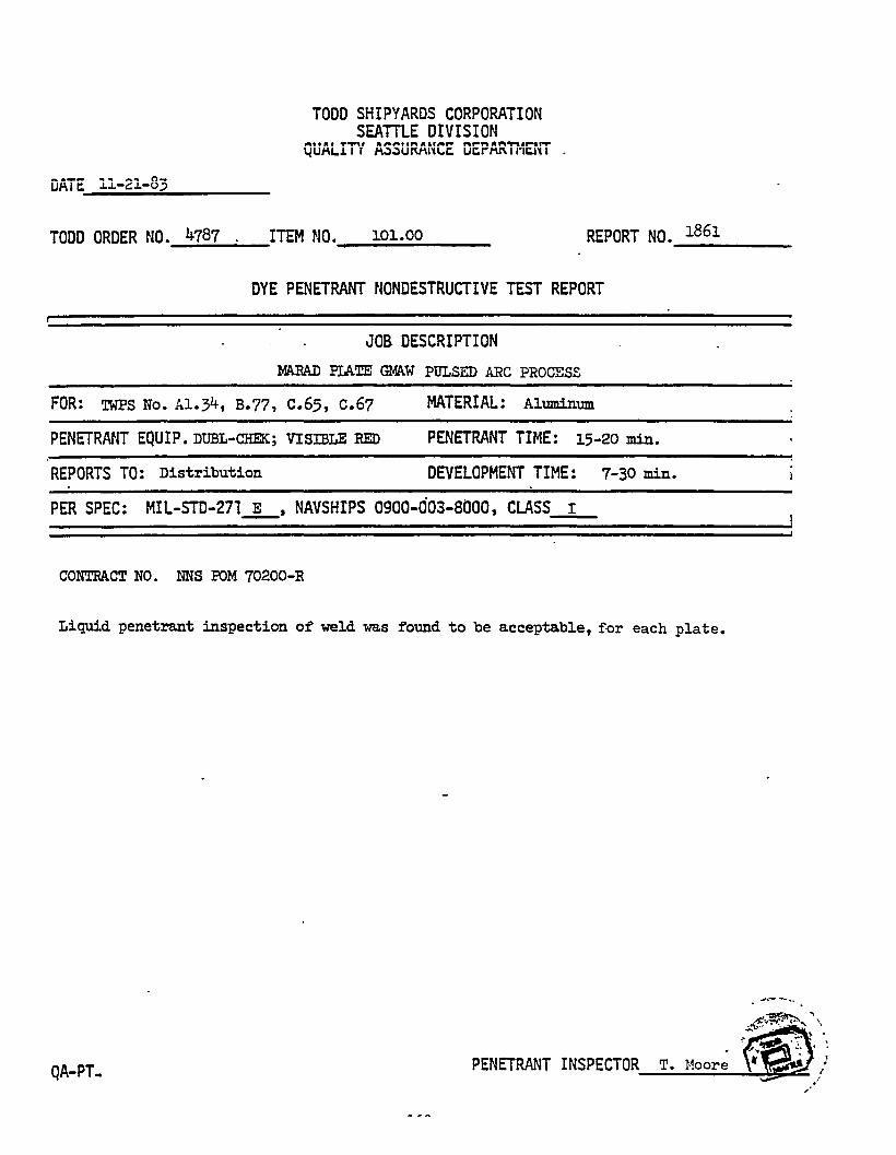
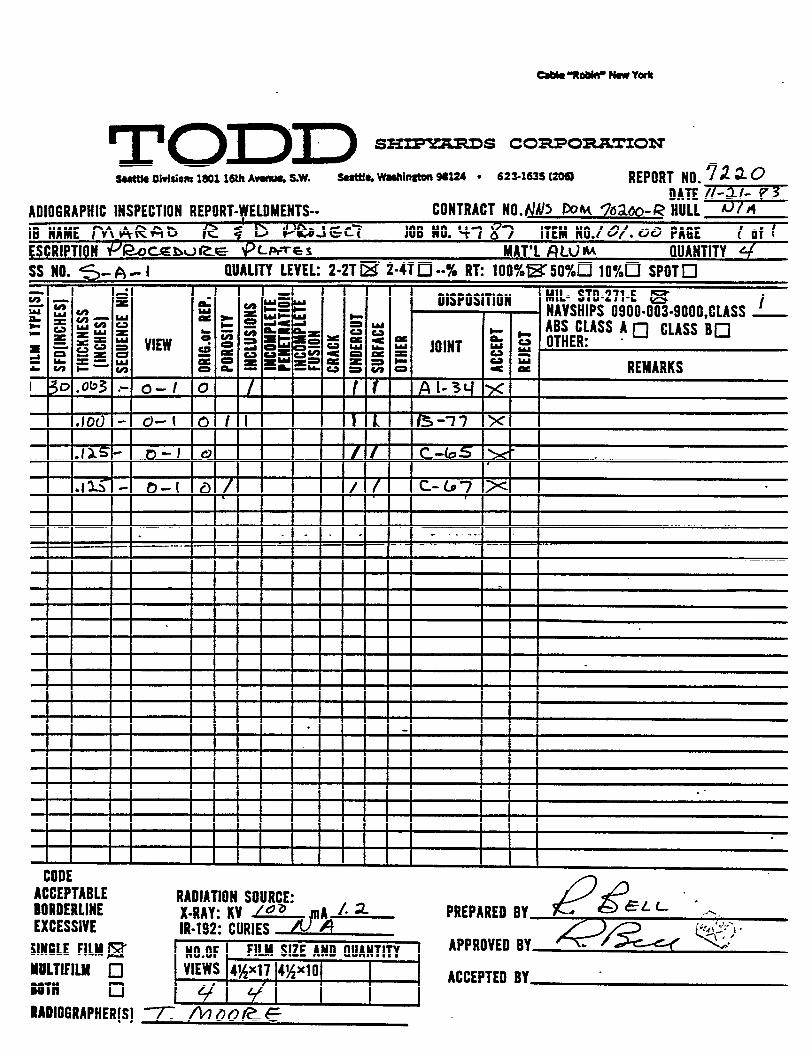
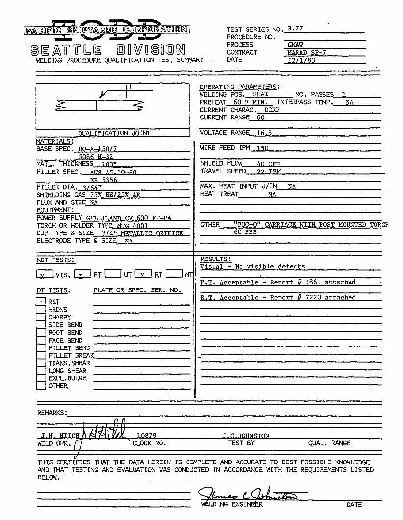

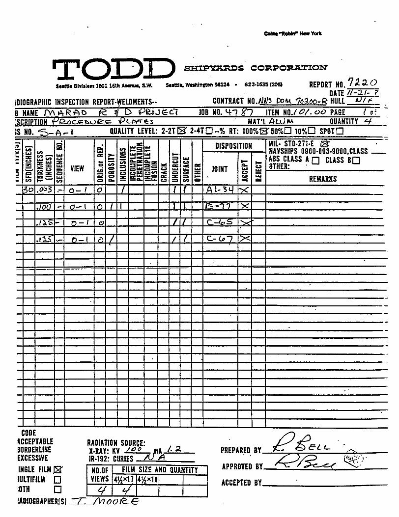
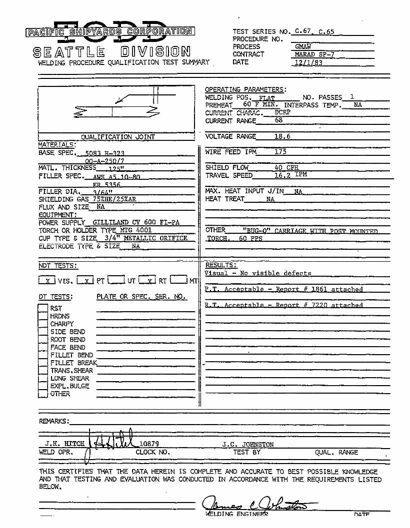
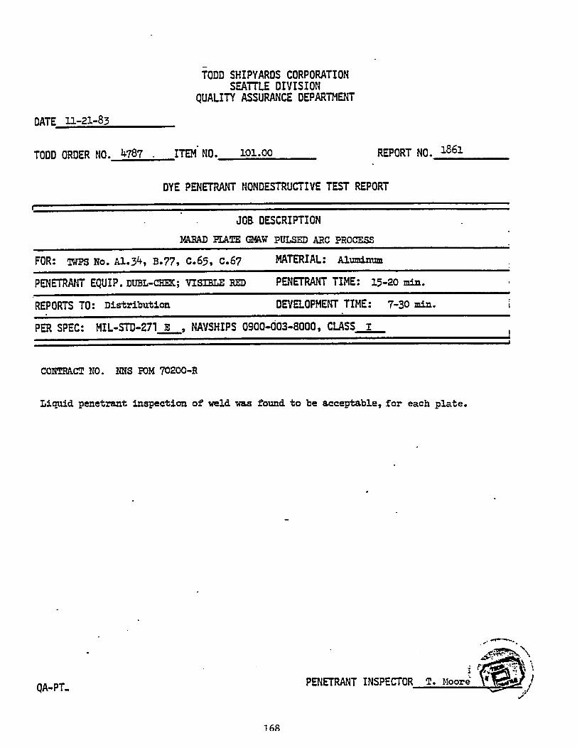
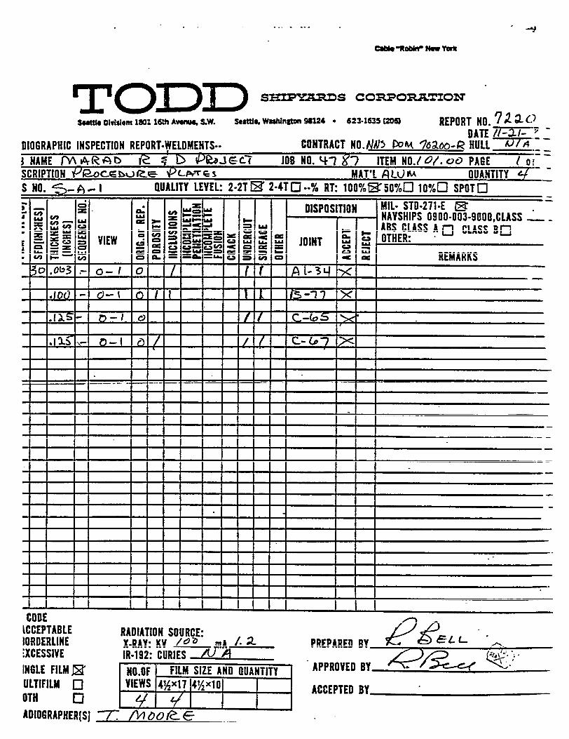
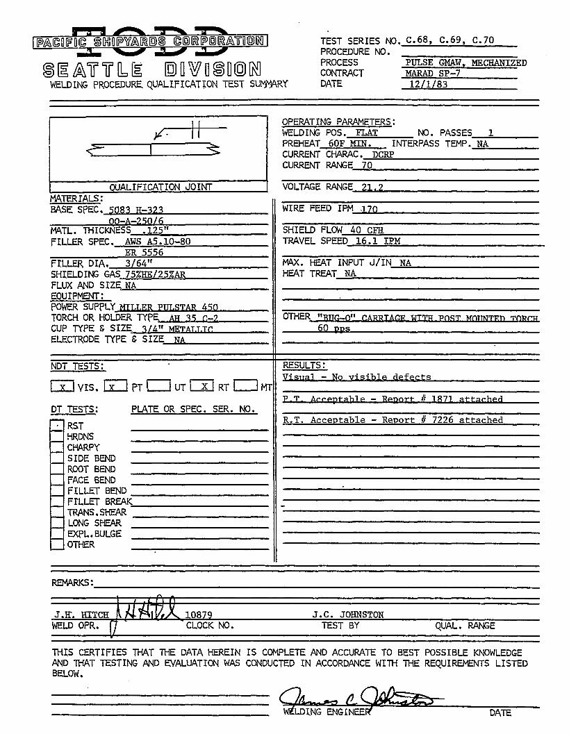
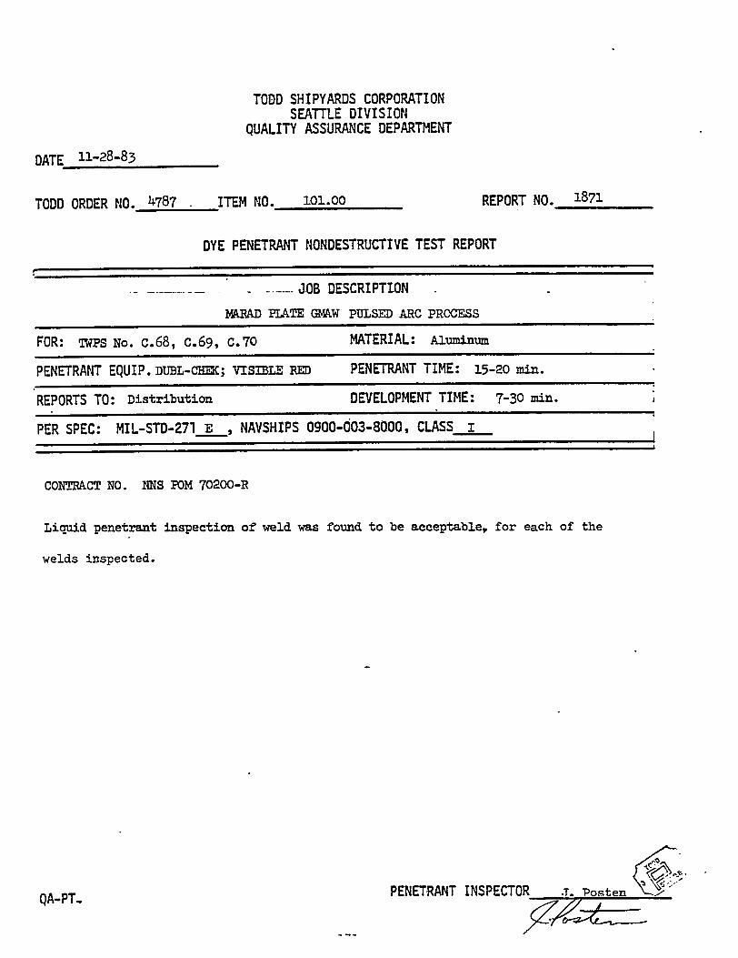
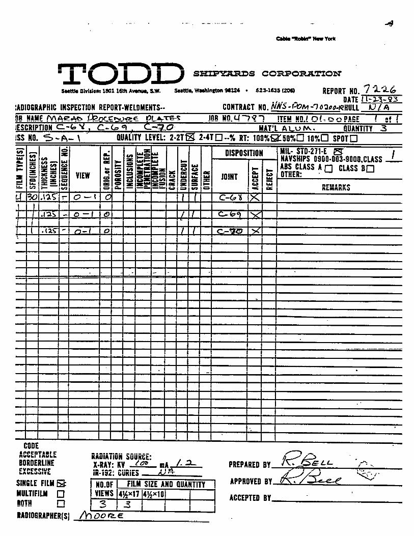
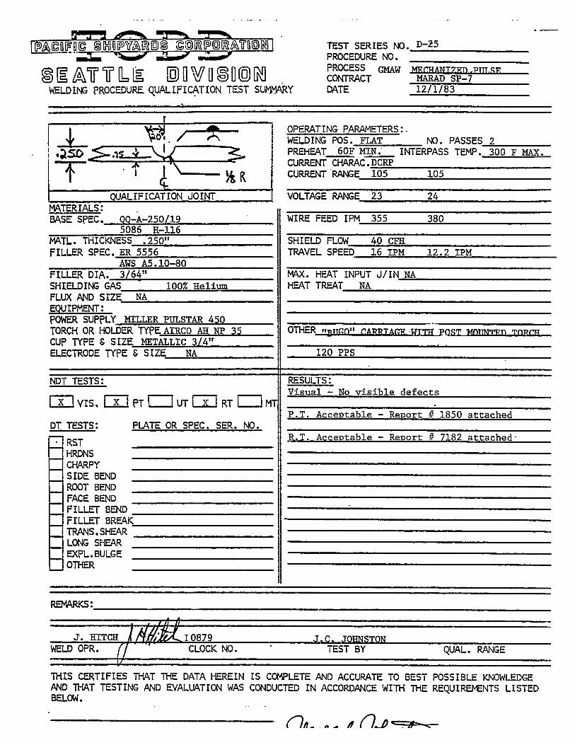

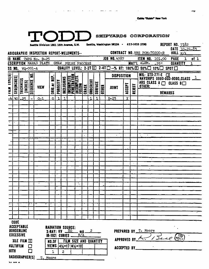
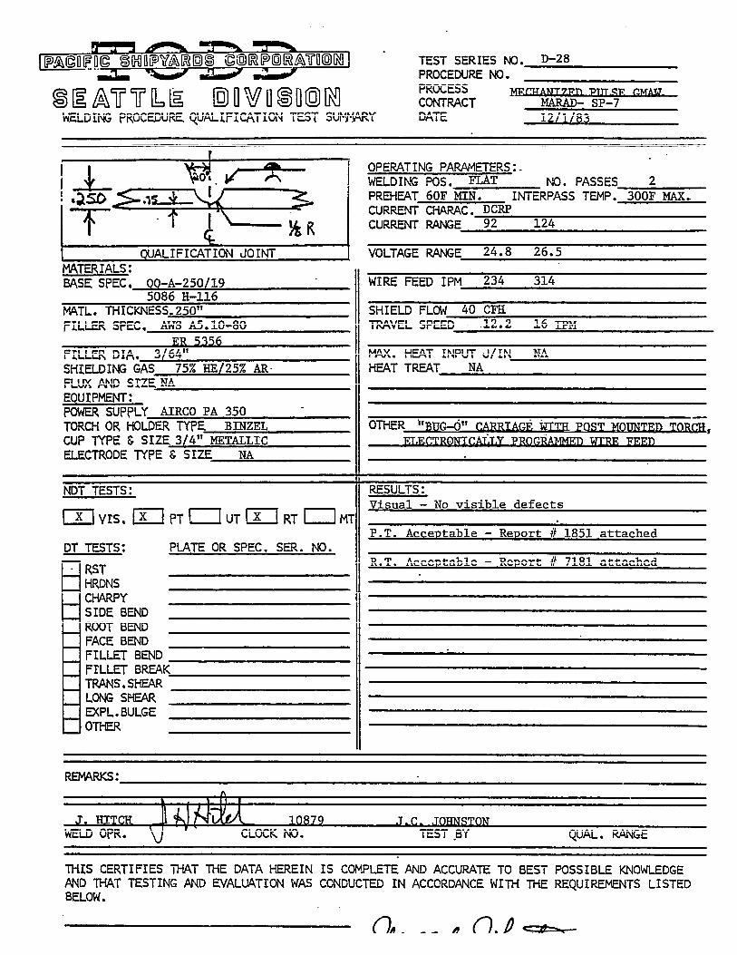
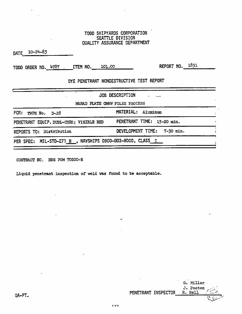
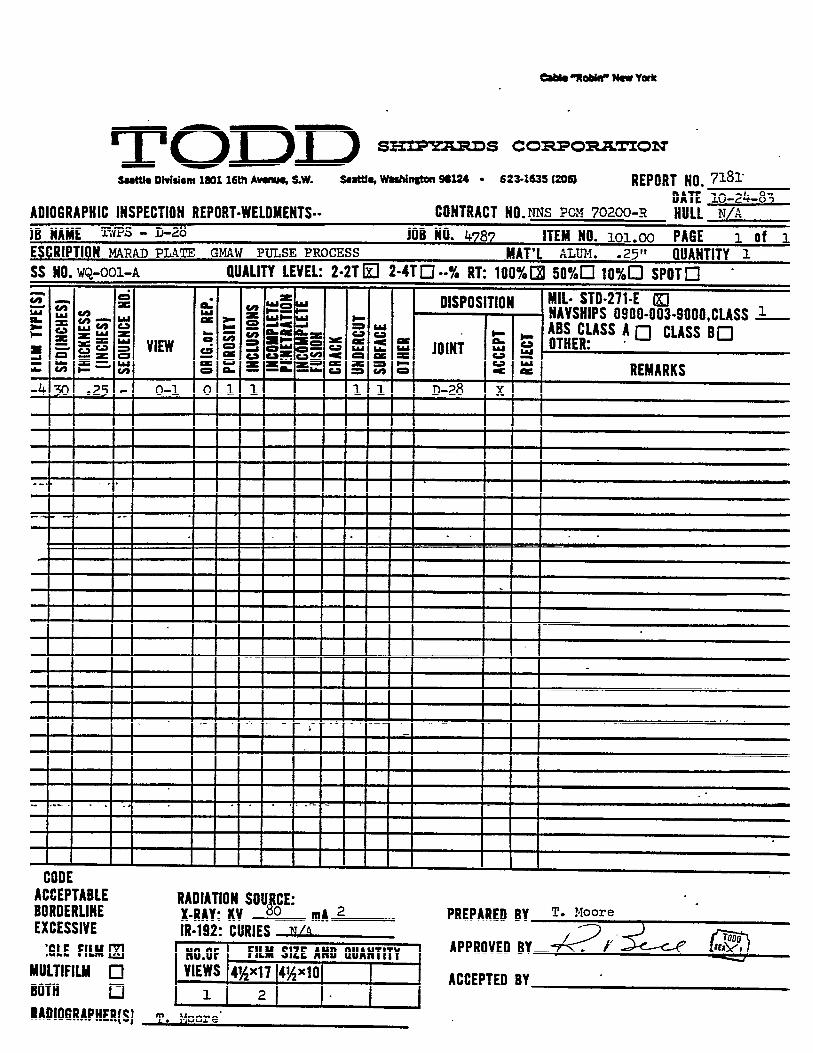
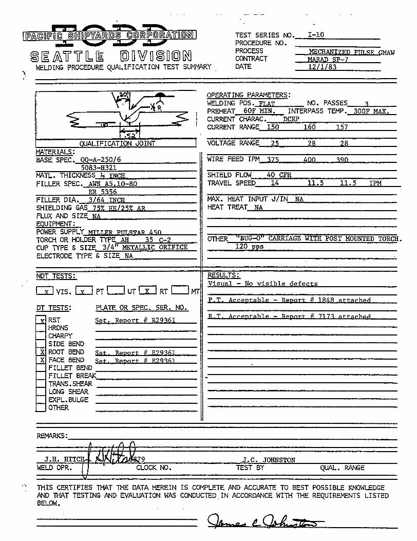

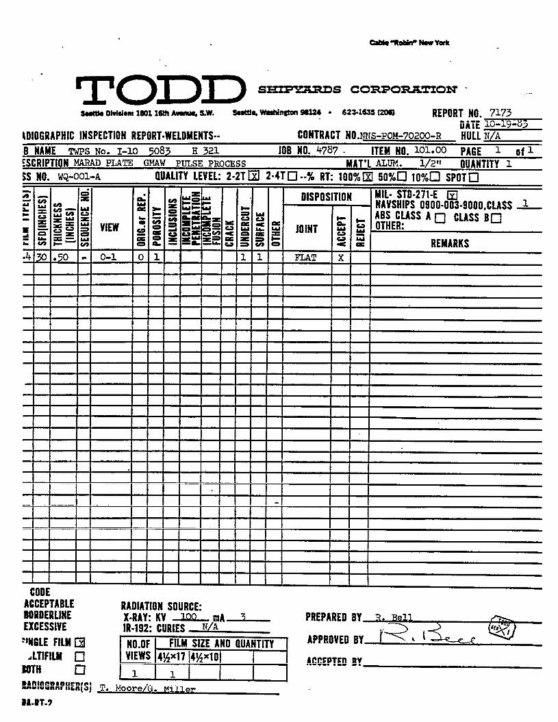
CHIPPING
The chipping gun is still the preferred
penetration reinforcement on the second
tool for removing
side. The method
excessive weld
still offers
the fastest cuts and best grooves for
ing for repair welding.
Excessive reinforcements on the torch
(second side) maybe removed with the
and should be worked to the high side
removing weld defects and prepar-
side (first side) and the back side
use of a flat configuration chisel
of the weld butt joint so that
the base material thickness will not be reduced. ln general, the other
half of the weld joint will fair in smoothly by itself.
Flat “V” and spoon shape chisels were made per sample from 401 Parker
taper shanks. All chisels were approximately 6 inches long x 13/32
inches diameter shank blanks. Figures 61 and 62 illustrate the
“V” and spoon configurations of chisels used.
Figure 63 is a photograph of the three chisel configurations.
flat
182
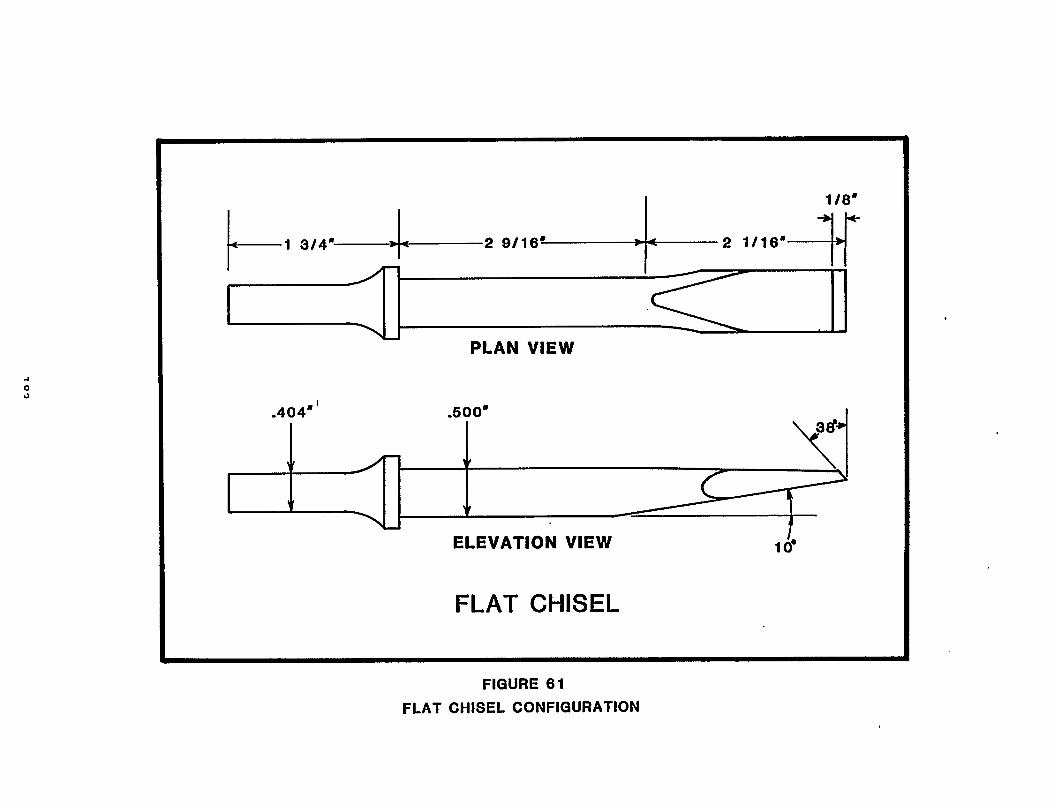
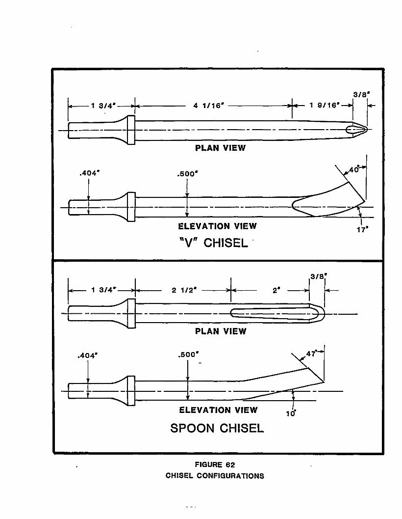
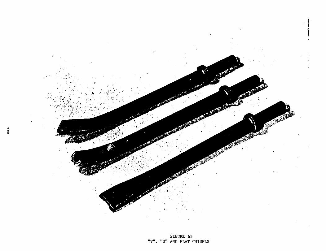
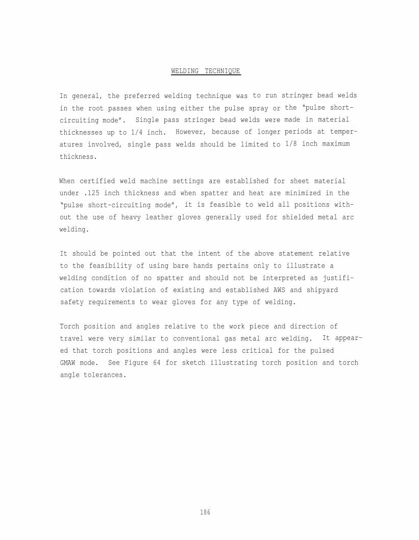
WELDING TECHNIQUE
In general, the preferred welding technique was to run stringer bead welds
in the root passes when using either the pulse spray or
circuiting mode”. Single pass stringer bead welds were
thicknesses up to 1/4 inch. However, because of longer
atures involved, single pass welds should be limited to
thickness.
the “pulse short-
made in material
periods at temper-
1/8 inch maximum
When certified weld machine settings are established for sheet material
under .125 inch thickness and when spatter and heat are minimized in the
“pulse short-circuiting mode”, it is feasible to weld all positions with-
out the use of heavy leather gloves generally used for shielded metal arc
welding.
It should be pointed out that the intent of the above statement relative
to the feasibility of using bare hands pertains only to illustrate a
welding condition of no spatter and should not be interpreted as justifi-
cation towards violation of existing and established AWS and shipyard
safety requirements to wear gloves for any type of welding.
Torch position and angles relative to the work piece and direction of
travel were very similar to conventional gas metal arc welding. It appear-
ed that torch positions and angles were less critical for the pulsed
GMAW mode. See Figure 64 for sketch illustrating torch position and torch
angle tolerances.
186
REPAIR WELDING
Only one repair with gas metal arc welding is allowed per MIL-STD-248
on all procedure qualification test panels. All repairs should be made
in the same manner as the original weld, i.e. implementing the same
welding power sources and accessories, welding position and original
standard. Although no repairs were required on the test panels submitted
for visual and radiographic inspection, it appears that standard repair
techniques could be applied very readily.
When full penetration welds are deposited from one side, lack of fusion
type defects are uncommon. On the other hand, incomplete fusion and
lack of fusion are rather common when aluminum plate/sheet is welded
from two sides, i.e. when the root weld beadc(s) from the first side
do not interpenetrate with the root beads from the second side, lack
of fusion on the joint side walls are common defects.
Incomplete weld penetration is usually caused because the welding current
is too low or welding travel speed is too fast.
Incomplete weld penetration is a significantly disastrous defect. Full
penetration welds on the side opposite the gas metal arc torch may be
visually inspected readily for incomplete penetration.
188
PREHEAT , INTERPASS , AND POST-HEAT TEMPERATURES
In general, no preheat is required except to remove moisture. A gentle soot
free oxy-gas torch flame or strip heaters may be used to provide uniform
temperature not exceeding 300F for tempered condition of 5000 series aluminum
alloys for marine fabrication. Preheat temperatures may be measured with a
surface pyrometer or other suitable temperature indicating devices.
Interpass temperatures should be kept as low as feasible.
Since 5000 series aluminum alloys are not heat treatable, no post-heat
requirement is necessary.
189
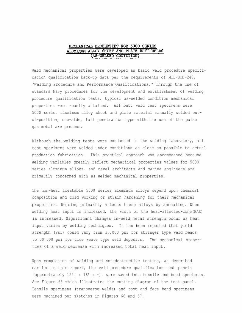
Weld mechanical properties were developed as basic weld procedure specifi-
cation qualification back-up data per the requirements of MIL-STD-248,
“Welding Procedure and Performance Qualifications." Through the use of
standard Navy procedures for the development and establishment of welding
procedure qualification tests, typical as-welded condition mechanical
properties were readily attained. All butt weld test specimens were
5000 series aluminum alloy sheet and plate material manually welded out-
of-position, one-side, full penetration type with the use of the pulse
gas metal arc process.
Although the welding tests were
test specimens were welded under
conducted in the welding laboratory, all
conditions as close as possible to actual
production fabrication. This practical approach was encompassed because
welding variables greatly reflect mechariical properties values for 5000
series aluminum alloys, and naval architects and marine engineers are
primarily concerned with as-welded mechanical properties.
The non-heat treatable 5000 series aluminum alloys depend upon chemical
composition and cold working or strain hardening for their mechanical
properties. Welding primarily affects these alloys by annealing. When
welding heat input is increased, the width of the heat-affected-zone(HAZ)
is increased. Significant changes in-weld metal strength occur as heat
input varies by welding techniques. It has been reported that yield
strength (Psi) could vary from 35,000 psi for stringer type weld beads
to 30,000 psi for tide weave type weld deposits. The mechanical proper-
ties of a weld decrease with increased total heat input.
Upon completion of welding and non-destructive testing, as described
earlier in this report, the weld procedure qualification test panels
(approximately 12”. x 16" x T), were sawed into tensile and bend specimens.
See Figure 65 which illustrates the cutting diagram of the test panel.
Tensile specimens (transverse welds) and root and face bend specimens
were machined per sketches in Figures 66 and 67.
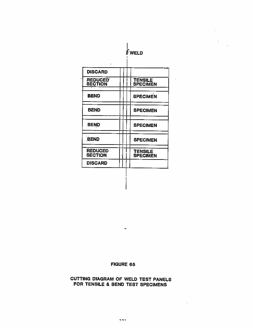
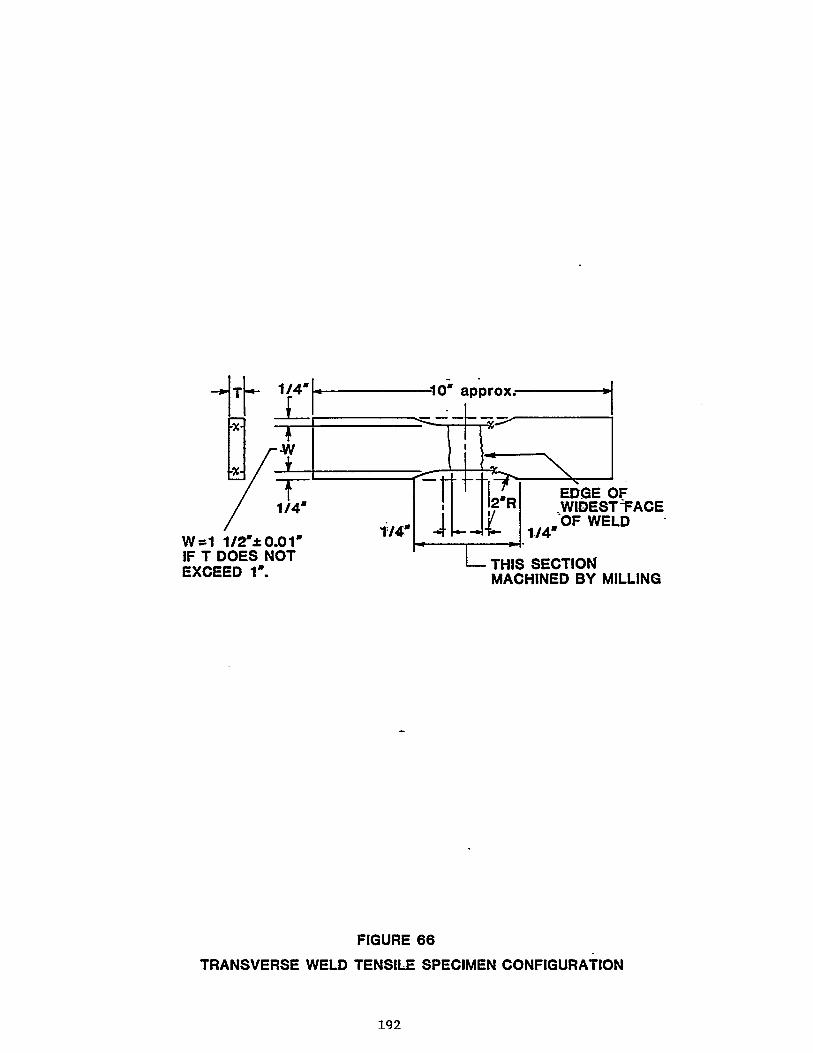
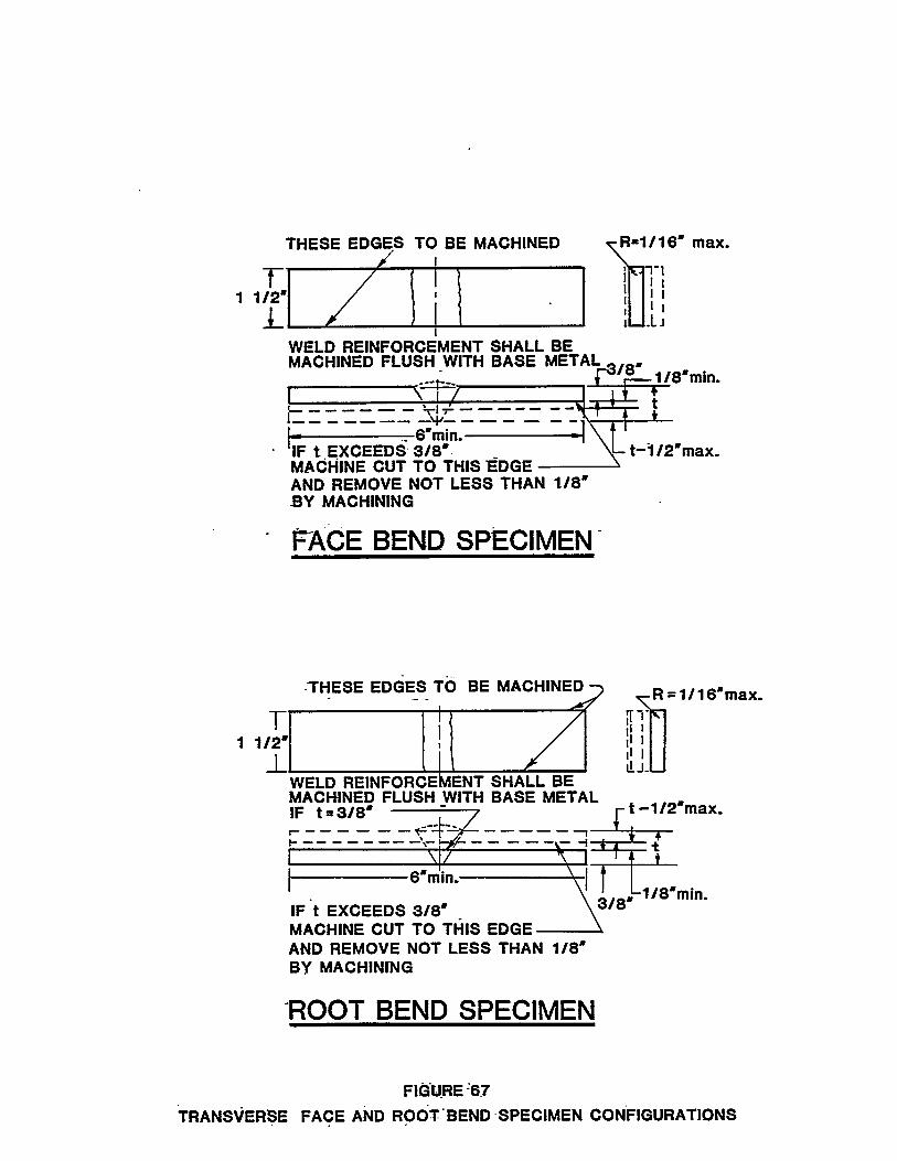

All surface and underbead
machining. A typical set
section tensile specimens
Figure 68.
weld reinforcements were removed flush by
of flush-machined, transverse weld, reduced
and root and face bend specimens are shown in
For convenience, the general welding parameters for mechanical property
test panels are listed according to their code identification numbers.
See Figure 69. For specific detailed information, see the following
section covering Machine Settings. Also, 5000 series aluminum alloy
"0” temper tensile and yield strengths are specified in Figure 70.
194
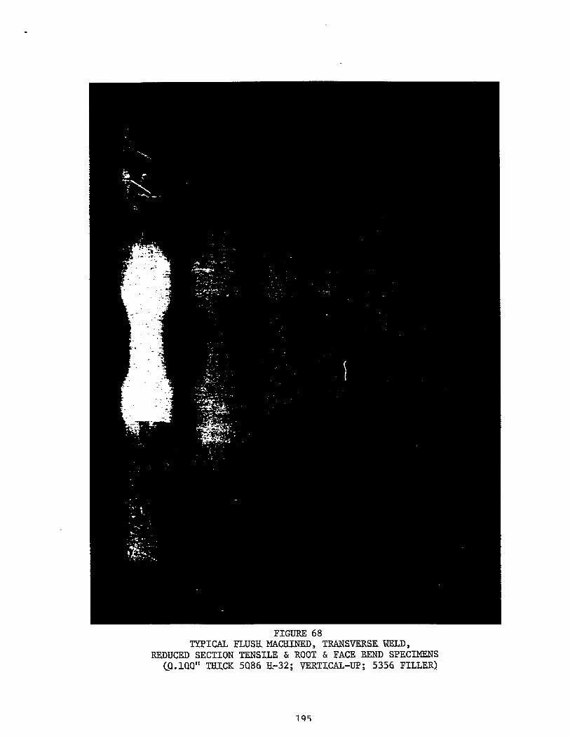
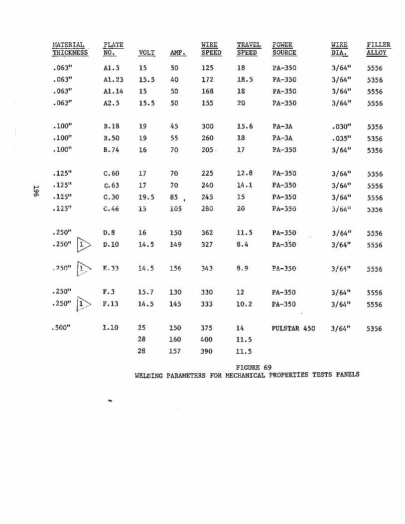
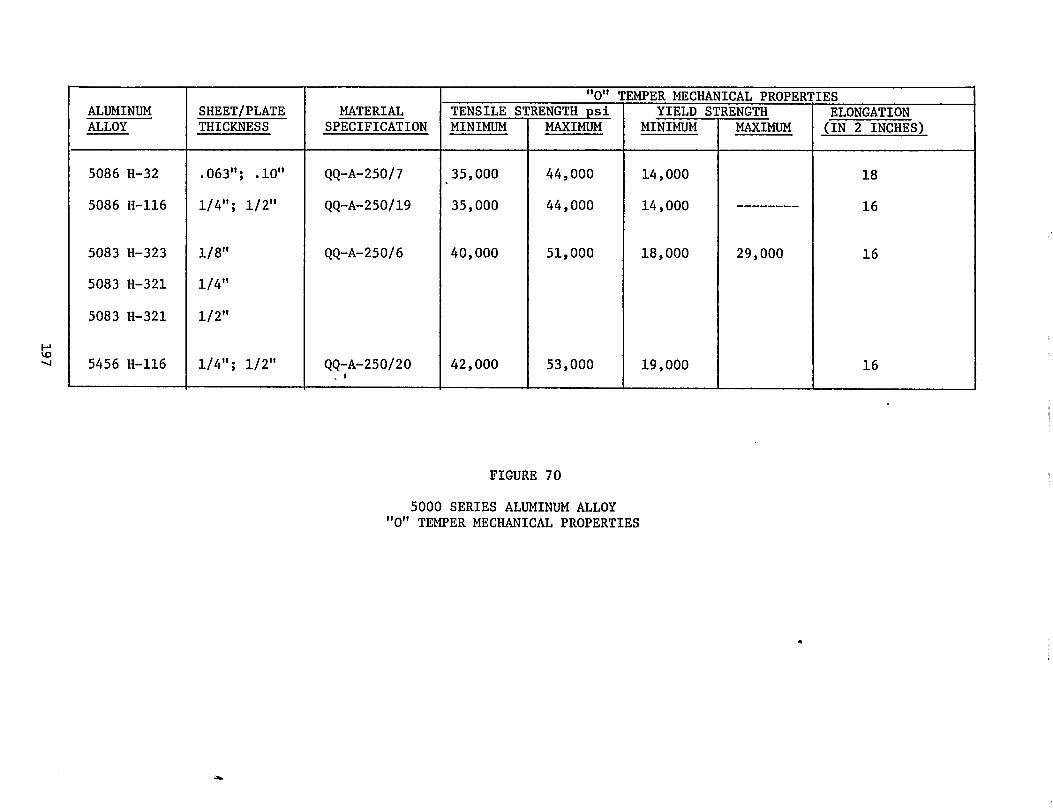
NORTHWEST LABORATORIES' REPORTS
All testing of weld mechanical properties specimens were conducted
at Northwest Laboratories in Seattle, Washington, an independent
testing laboratory. AIS of the aluminum alloy test specimens were
tested on a Tinius Olson Super “L” Universal Testing Machine cali-
brated one step removed from the National Bureau of Standards.
This machine was calibrated on April 8, 1983 by Pacific Scientific
Company.
The following
Laboratories'
pages cover specific and pertinmt detailed Northwest
reports covering out-of-position, one-side, full pene-
tration manual pulse gas metal arc butt welding of 5000 series alumi-
num alloy sheet and plate. A summary of the mechanical properties
data, and photographs of the mechanical properties specimens after
destructive testing are shown in Figures 71, 72, and 73.
198
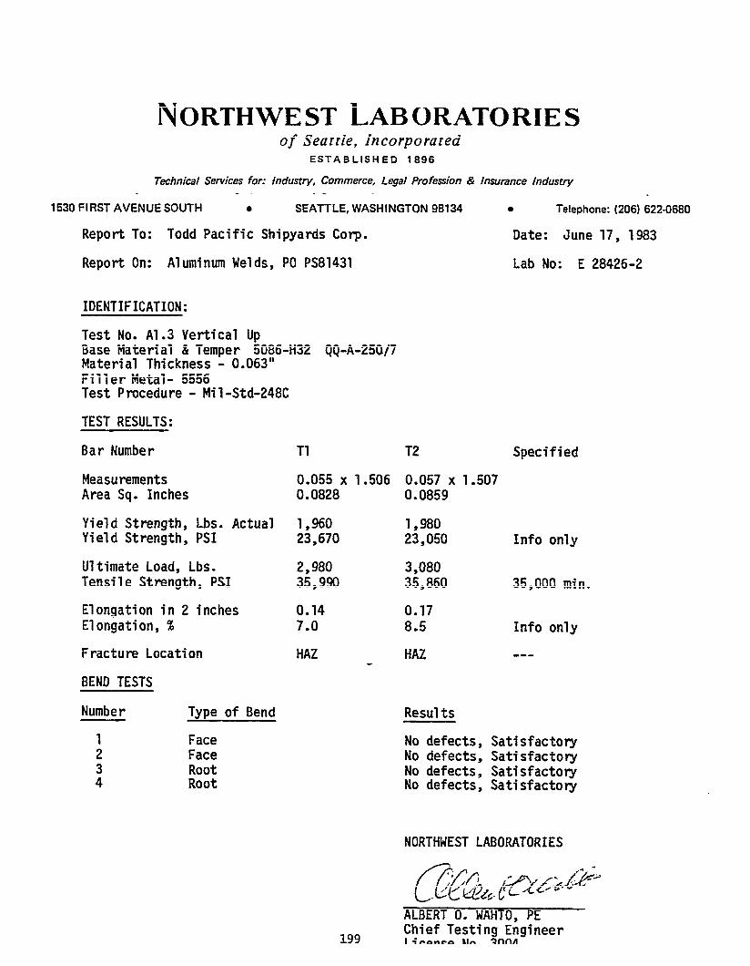
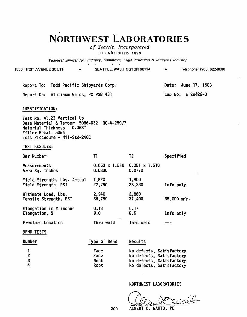
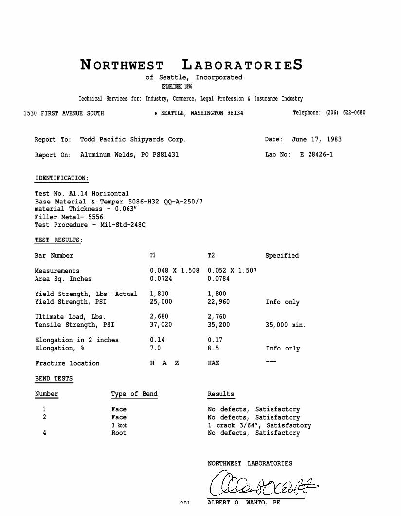
N ORTHWEST L ABORATORIESof Seattle, Incorporated
ESTABLISHED 1896
Technical Services for: Industry, Commerce, Legal Profession & Insurance Industry
1530 FIRST AVENUE SOUTH • SEATTLE, WASHINGTON 98134 Telephone: (206) 622-0680
Report To: Todd Pacific Shipyards Corp. Date: June 17, 1983
Report On: Aluminum Welds, PO PS81431 Lab No: E 28426-1
IDENTIFICATION:
Test No. Al.14 HorizontalBase Material & Temper 5086-H32 QQ-A-250/7material Thickness - 0.063”Filler Metal- 5556Test Procedure - Mil-Std-248C
TEST RESULTS:
Bar Number T1
Measurements 0.048 X 1.508Area Sq. Inches 0.0724
Yield Strength, Lbs. Actual 1,810Yield Strength, PSI 25,000
Ultimate Load, Lbs. 2,680Tensile Strength, PSI 37,020
Elongation in 2 inches 0.14Elongation, % 7.0
Fracture Location H A Z
BEND TESTS
Number Type of Bend
1 Face2 Face
3 Root4 Root
201
SpecifiedT2
0.052 X 1.5070.0784
1,80022,960 Info only
2,76035,200 35,000 min.
0.178.5 Info only
HAZ ---
Results
No defects, SatisfactoryNo defects, Satisfactory1 crack 3/64”, SatisfactoryNo defects, Satisfactory
NORTHWEST LABORATORIES
ALBERT O. WAHTO, PE
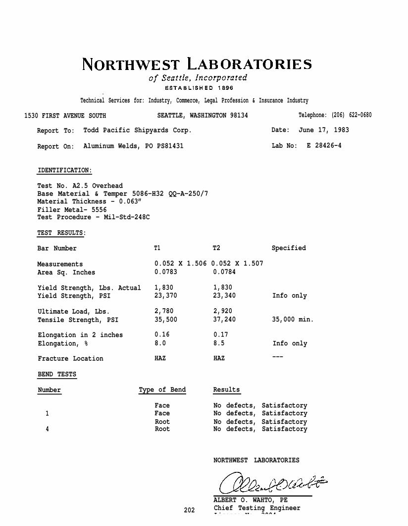
Technical Services for: Industry, Commerce, Legal Profession & Insurance Industry
1530 FIRST AVENUE SOUTH SEATTLE, WASHINGTON 98134 Telephone: (206) 622-0680
Report To: Todd Pacific Shipyards Corp. Date: June 17, 1983
Report On: Aluminum Welds, PO PS81431 Lab No: E 28426-4
IDENTIFICATION:
Test No. A2.5 OverheadBase Material & Temper 5086-H32 QQ-A-250/7Material Thickness - 0.063”Filler Metal- 5556Test Procedure - Mil-Std-248C
TEST RESULTS:
Bar Number T1 T2 Specified
Measurements 0.052 X 1.506 0.052 X 1.507Area Sq. Inches 0.0783 0.0784
Yield Strength, Lbs. Actual 1,830 1,830Yield Strength, PSI
Ultimate Load, Lbs.Tensile Strength, PSI
Elongation in 2 inchesElongation, %
Fracture Location
BEND TESTS
Number
1
4
23,370
2,78035,500
0.168.0
HAZ
Type of Bend
FaceFaceRootRoot
23,340
2,92037,240
0.178.5
HAZ
Results
Info only
35,000 min.
Info only
---
No defects, SatisfactoryNo defects, SatisfactoryNo defects, SatisfactoryNo defects, Satisfactory
NORTHWEST LABORATORIES
202
ALBERT O. WAHTO, PEChief Testing EngineerLicense No 3004
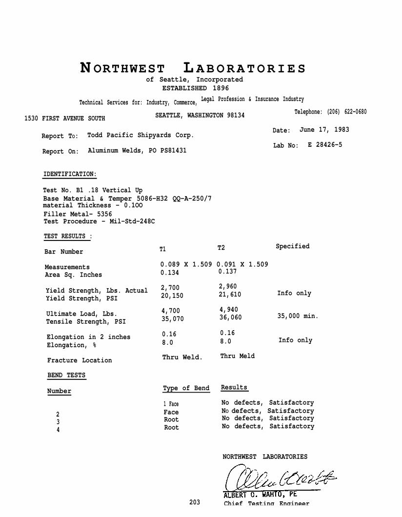
N ORTHWEST L ABORATORIESof Seattle, Incorporated
ESTABLISHED 1896
Technical Services for: Industry, Commerce, Legal Profession & Insurance Industry
1530 FIRST AVENUE SOUTH SEATTLE, WASHINGTON 98134 Telephone: (206) 622-0680
Todd Pacific Shipyards Corp.Date: June 17, 1983
Report TO:
Aluminum Welds, PO PS81431Lab No: E 28426-5
Report On:
IDENTIFICATION:
Test No. B1 .18 Vertical UpBase Material & Temper 5086-H32 QQ-A-250/7material Thickness - 0.1OOFiller Metal- 5356Test Procedure - Mil-Std-248C
TEST RESULTS :
T1 T2 SpecifiedBar Number
MeasurementsArea Sq. Inches
0.089 X 1.509 0.091 X 1.5090.134 0.137
Yield Strength, Lbs. Actual 2,700
Yield Strength, PSI 20,150
Ultimate Load, Lbs.Tensile Strength, PSI
4,70035,070
Elongation in 2 inches 0.16
Elongation, % 8.0
2,96021,610
4,94036,060
0.168.0
Info only
35,000 min.
Info only
Fracture Location Thru Weld. Thru Meld
BEND TESTS
Number Type of Bend Results
1 Face No defects, Satisfactory
2 Face NO defects, Satisfactory
3 Root No defects, Satisfactory
4 Root No defects, Satisfactory
NORTHWEST LABORATORIES
203 Chief Testing Engineer
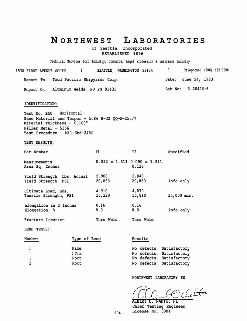
N O R T H W E S T L A B O R A T O R I E S of Seattle, Incorporated
ESTABLISHED 1896
Technical Services for: Industry, Commerce, Legal Profession & Insurance Industry
1530 FIRST AVENUE SOUTH l SEATTLE, WASHINGTON 98134 l Telephone: (206) 622-0680
Report To: Todd Pacific Shipyards Corp. Date: June 24, 1983
Report On: Aluminum Welds, PO PS 81431 Lab No: E 28426-6
IDENTIFICATION:
Test No. B50 HorizontalBase Material and Temper - 5086 H-32 QQ-A-250/7Material Thickness - 0.100”Filler Metal - 5356Test Procedure - Mil-Std-248C
TEST RESULTS:
Bar Number T1 T2 Specified
MeasurementsArea Sq. Inches
Yield Strength, Lbs. ActualYield Strength, PSI
Ultimate Load, Lbs.Tensile Strength, PSI
elongation in 2 InchesElongation, %
Fracture Location
BEND TESTS:
0.092 x 1.511 0.090 x 1.5110.136
2,90020,860
4,91035,320
0.168.0
Thru Weld
Number Type of Bend
1 Face2 Face
1 Root2 Root
2,84020,880 Info only
4,87035,810 35,000 min.
0.168.0 Info only
Thru Weld
Results
No defects, SatisfactoryNo defects, SatisfactoryNo defects, SatisfactoryNo defects, Satisfactory
NORTHWEST LABORATORY ES
204
Chief Testing EngineerLicense No. 3004
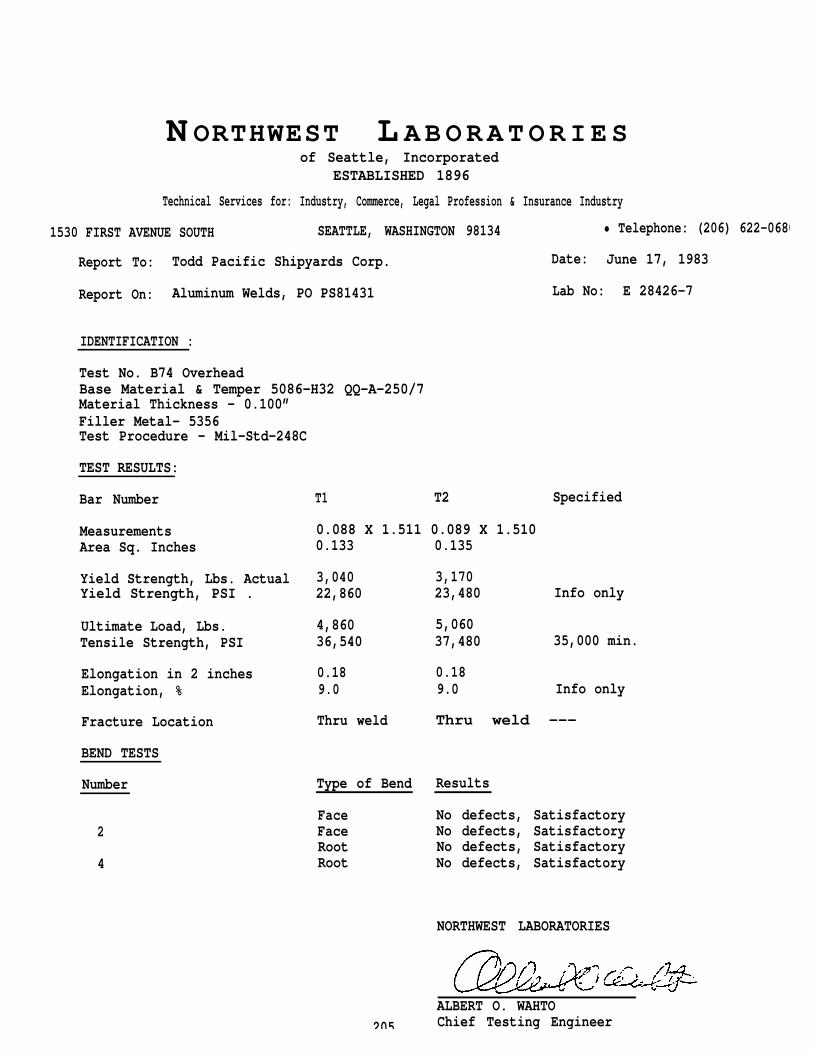
N ORTHWEST L ABORATORIESof Seattle, Incorporated
ESTABLISHED 1896
Technical Services for: Industry, Commerce, Legal Profession & Insurance Industry
1530 FIRST AVENUE SOUTH SEATTLE, WASHINGTON 98134 • Telephone: (206) 622-0680
Report To: Todd Pacific Shipyards Corp. Date: June 17, 1983
Report On: Aluminum Welds, PO PS81431 Lab No: E 28426-7
IDENTIFICATION :
Test No. B74 OverheadBase Material & Temper 5086-H32 QQ-A-250/7Material Thickness - 0.100”Filler Metal- 5356Test Procedure - Mil-Std-248C
TEST RESULTS:
Bar Number
MeasurementsArea Sq. Inches
Yield Strength, Lbs. ActualYield Strength, PSI .
Ultimate Load, Lbs.Tensile Strength, PSI
Elongation in 2 inchesElongation, %
Fracture Location
BEND TESTS
Number
2
4
T1 T2 Specified
0.088 X 1.511 0.089 X 1.5100.133
3,04022,860
4,86036,540
0.189.0
Thru weld
Type of Bend
FaceFaceRootRoot
205
0.135
3,17023,480 Info only
5,06037,480 35,000 min.
0.189.0 Info only
Thru weld ---
Results
No defects, SatisfactoryNo defects, SatisfactoryNo defects, SatisfactoryNo defects, Satisfactory
NORTHWEST LABORATORIES
ALBERT O. WAHTOChief Testing Engineer
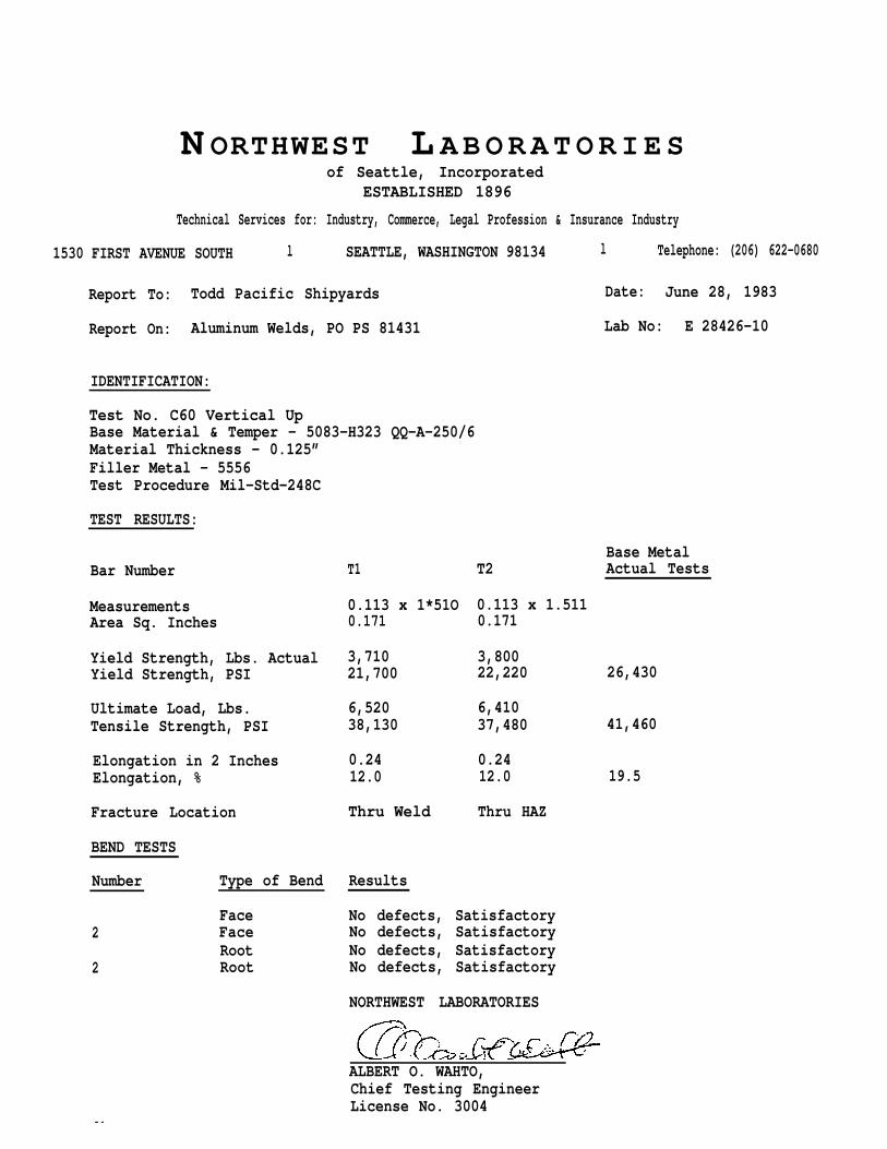
N ORTHWEST L ABORATORIESof Seattle, Incorporated
ESTABLISHED 1896
Technical Services for: Industry, Commerce, Legal Profession & Insurance Industry
1530 FIRST AVENUE SOUTH l SEATTLE, WASHINGTON 98134 l Telephone: (206) 622-0680
Report To: Todd Pacific Shipyards Date: June 28, 1983
Report On: Aluminum Welds, PO PS 81431 Lab No: E 28426-10
IDENTIFICATION:
Test No. C60 Vertical UpBase Material & Temper - 5083-H323 QQ-A-250/6Material Thickness - 0.125”Filler Metal - 5556Test Procedure Mil-Std-248C
TEST RESULTS:
Bar Number
MeasurementsArea Sq. Inches
Yield Strength, Lbs. ActualYield Strength, PSI
Ultimate Load, Lbs.Tensile Strength, PSI
Elongation in 2 InchesElongation, %
Fracture Location
BEND TESTS
Number Type of Bend
Face2 Face
Root2 Root
T1
0.113 x 1*51O0.171
3,71021,700
6,52038,130
0.2412.0
Thru Weld
Base MetalT2 Actual Tests
0.113 x 1.5110.171
3,80022,220 26,430
6,41037,480 41,460
0.2412.0 19.5
Thru HAZ
Results
No defects, SatisfactoryNo defects, SatisfactoryNo defects, SatisfactoryNo defects, Satisfactory
NORTHWEST LABORATORIES
ALBERT O. WAHTO,Chief Testing EngineerLicense No. 3004
lb
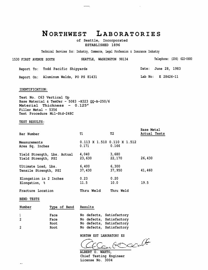
—-——. -
N ORTHWEST L ABORATORIESof Seattle, Incorporated
ESTABLISHED 1896
Technical Services for: Industry, Commerce, Legal Profession & Insurance Industry
1530 FIRST AVENUE SOUTH SEATTLE, WASHINGTON 98134 Telephone: (206) 622-0680
Report To: Todd Pacific Shipyards Date: June 28, 1983
Report On: Aluminum Welds, PO PS 81431 Lab No: E 28426-11
IDENTIFICATION:
Test No. C63 Vertical UpBase Material & TemUer - 5083 -H323 QQ-A-250/6Material Thickness - 0.125” Filler Metal - 5356Test Procedure Mil-Std-248C
TEST RESULTS:
Bar Number
MeasurementsArea Sq. Inches
Yield Strength, Lbs. ActualYield Strength, PSI
Ultimate Load, Lbs.Tensile Strength, PSI
Elongation in 2 InchesElongation, %
Fracture Location
BEND TESTS
Number Type of Bend
1 Face2 Face
Root2 Root
T1 T2
0.113 X 1.510 0.110 X 1.5120.171 0.166
Base MetalActual Tests
4,040 3,68023,630 22,170 26,430
6,400 6,30037,430 37,950 41,460
0.23 0.2011.5 10.0 19.5
Thru Weld Thru Weld
Results
No defects, SatisfactoryNo defects, SatisfactoryNo defects, SatisfactoryNo defects, Satisfactory
NORTHW EST LABORATORY ES
ALBERT O. WAHTO,
lb
Chief Testing EngineerLicense No. 3004
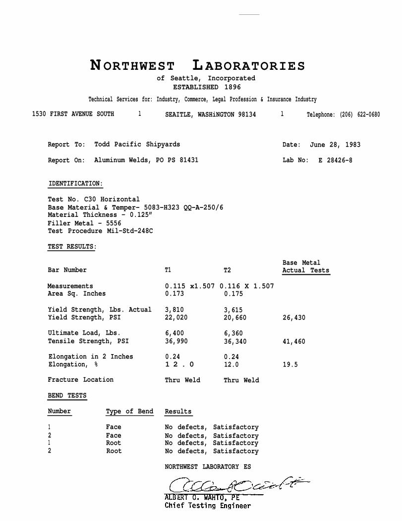
N ORTHWEST L ABORATORIES of Seattle, Incorporated
ESTABLISHED 1896
Technical Services for: Industry, Commerce, Legal Profession & Insurance Industry
1530 FIRST AVENUE SOUTH l SEAITLE, WASHiNGTON 98134 l Telephone: (206) 622-0680
Report To: Todd Pacific Shipyards Date: June 28, 1983
Report On: Aluminum Welds, PO PS 81431 Lab No: E 28426-8
IDENTIFICATION:
Test No. C30 HorizontalBase Material & Temper- 5083-H323 QQ-A-250/6Material Thickness - 0.125”Filler Metal - 5556Test Procedure Mil-Std-248C
TEST RESULTS:
Base MetalBar Number T1 T2 Actual Tests
Measurements 0.115 x1.507 0.116 X 1.507Area Sq. Inches 0.173 0.175
Yield Strength, Lbs. Actual 3,810 3,615Yield Strength, PSI 22,020 20,660 26,430
Ultimate Load, Lbs. 6,400 6,360Tensile Strength, PSI 36,990 36,340 41,460
Elongation in 2 Inches 0.24 0.24Elongation, % 1 2 . 0 12.0 19.5
Fracture Location Thru Weld Thru Weld
BEND TESTS
Number Type of Bend Results
1 Face No defects, Satisfactory2 Face No defects, Satisfactory1 Root No defects, Satisfactory2 Root No defects, Satisfactory
NORTHWEST LABORATORY ES
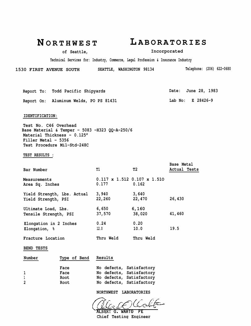
N O R T H W E S T L ABORATORIESof Seattle, Incorporated
Technical Services for: Industry, Commerce, Legal Profession & Insurance Industry
1530 FIRST AVENUE SOUTH SEATTLE, WASHINGTON 98134 Telephone: (206) 622-0680
Report To: Todd Pacific Shipyards Date: June 28, 1983
Report On: Aluminum Welds, PO PS 81431 Lab No: E 28426-9
IDENTIFICATION:
Test No. C46 Overhead Base Material & Temper - 5083 -H323 QQ-A-250/6Material Thickness - 0.125”Filler Metal - 5356Test Procedure Mi1-Std-248C
TEST RESULTS :
Bar Number
MeasurementsArea Sq. Inches
Yield Strength, Lbs. ActualYield Strength, PSI
Ultimate Load, Lbs.Tensile Strength, PSI
Elongation in 2 InchesElongation, %
Fracture Location
BEND TESTS
Number Type of Bend
Face1 Face1 Root2 Root
Base MetalT1 T2 Actual Tests
0.117 x 1.512 0.107 x 1.51O0.177 0.162
3,940 3,64022,260 22,470 26,430
6,650 6,16037,570 38,020 41,460
0.24 0.2012.0 10.0 19.5
Thru Weld Thru Weld
Results
No defects, SatisfactoryNo defects, SatisfactoryNo defects, SatisfactoryNo defects, Satisfactory
NORTHWEST LABORATORIES
Chief Testing Engineer
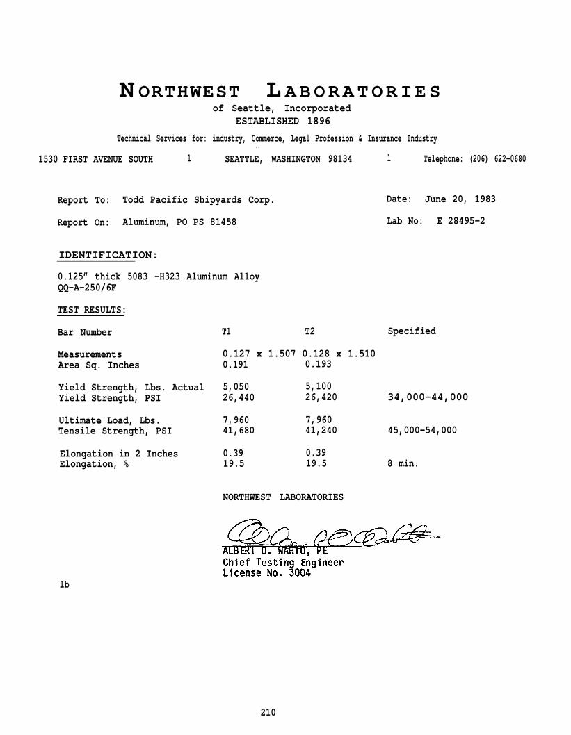
N ORTHWEST L ABORATORIESof Seattle, Incorporated
ESTABLISHED 1896
Technical Services for: industry, Commerce, Legal Profession & Insurance Industry. .
1530 FIRST AVENUE SOUTH l SEATTLE, WASHINGTON 98134 l Telephone: (206) 622-0680
Report To: Todd Pacific Shipyards Corp. Date: June 20, 1983
Report On: Aluminum, PO PS 81458 Lab No: E 28495-2
IDENTIFICATION:
0.125” thick 5083 -H323 Aluminum Al1oyQQ-A-250/6F
TEST RESULTS:
Bar Number T1 T2 Specified
Measurements 0.127 x 1.507 0.128 x 1.510Area Sq. Inches 0.191 0.193
Yield Strength, Lbs. Actual 5,050 5,100Yield Strength, PSI 26,440 26,420 34,000-44,000
Ultimate Load, Lbs. 7,960 7,960Tensile Strength, PSI 41,680 41,240 45,000-54,000
Elongation in 2 Inches 0.39 0.39Elongation, % 19.5 19.5 8 min.
NORTHWEST LABORATORIES
lb
210
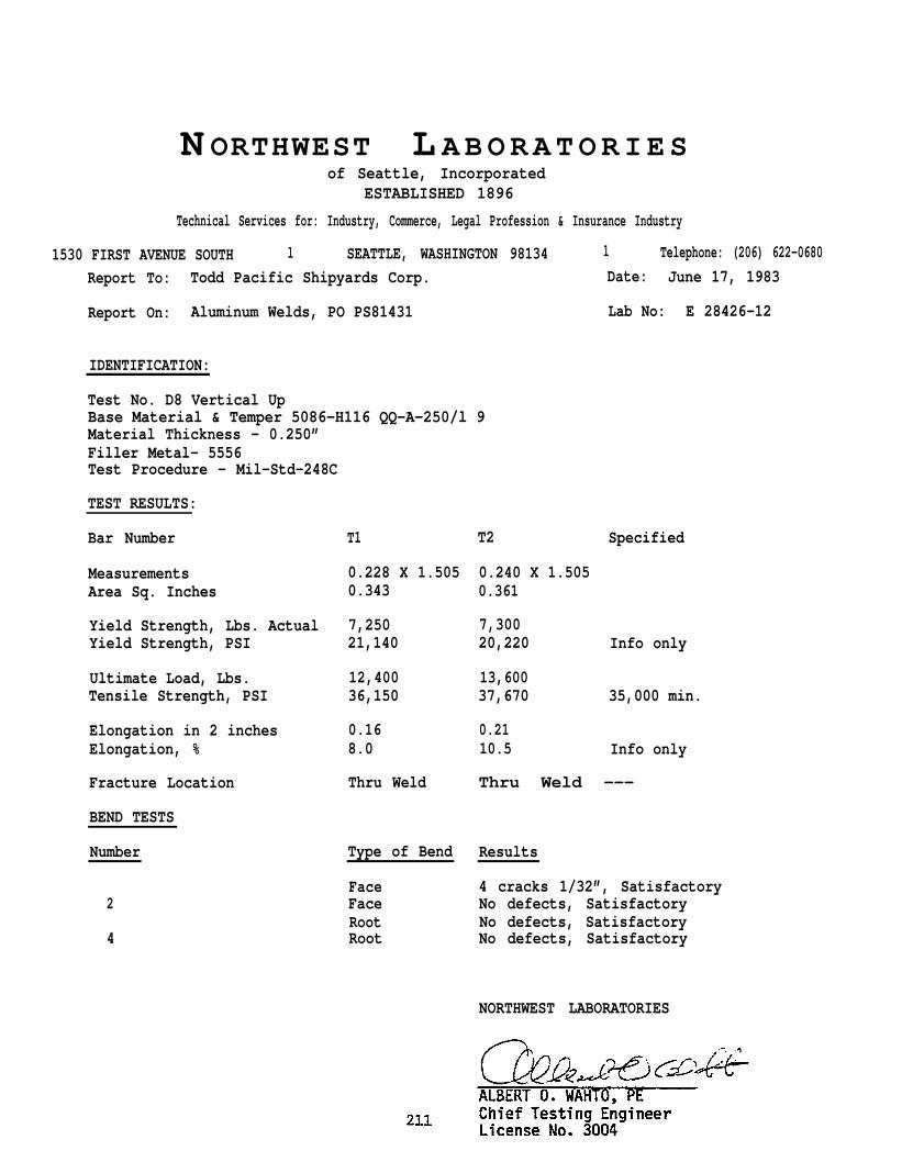
N ORTHWEST L ABORATORIESof Seattle, Incorporated
ESTABLISHED 1896
Technical Services for: Industry, Commerce, Legal Profession & Insurance Industry
1530 FIRST AVENUE SOUTH l SEATTLE, WASHINGTON 98134 l Telephone: (206) 622-0680
Report To: Todd Pacific Shipyards Corp. Date: June 17, 1983
Report On: Aluminum Welds, PO PS81431 Lab No: E 28426-12
IDENTIFICATION:
Test No. D8 Vertical UpBase Material & Temper 5086-H116 QQ-A-250/l 9Material Thickness - 0.250”Filler Metal- 5556Test Procedure - Mil-Std-248C
TEST RESULTS:
Bar Number
MeasurementsArea Sq. Inches
Yield Strength, Lbs. ActualYield Strength, PSI
Ultimate Load, Lbs.Tensile Strength, PSI
Elongation in 2 inchesElongation, %
Fracture Location
BEND TESTS
T1
0.228 X 1.5050.343
7,25021,140
12,40036,150
0.168.0
Thru Weld
T2 Specified
0.240 X 1.5050.361
7,30020,220 Info only
13,60037,670 35,000 min.
0.2110.5 Info only
Thru Weld ---
Number Type of Bend Results
Face 4 cracks 1/32”, Satisfactory2 Face No defects, Satisfactory
Root No defects, Satisfactory4 Root No defects, Satisfactory
NORTHWEST LABORATORIES
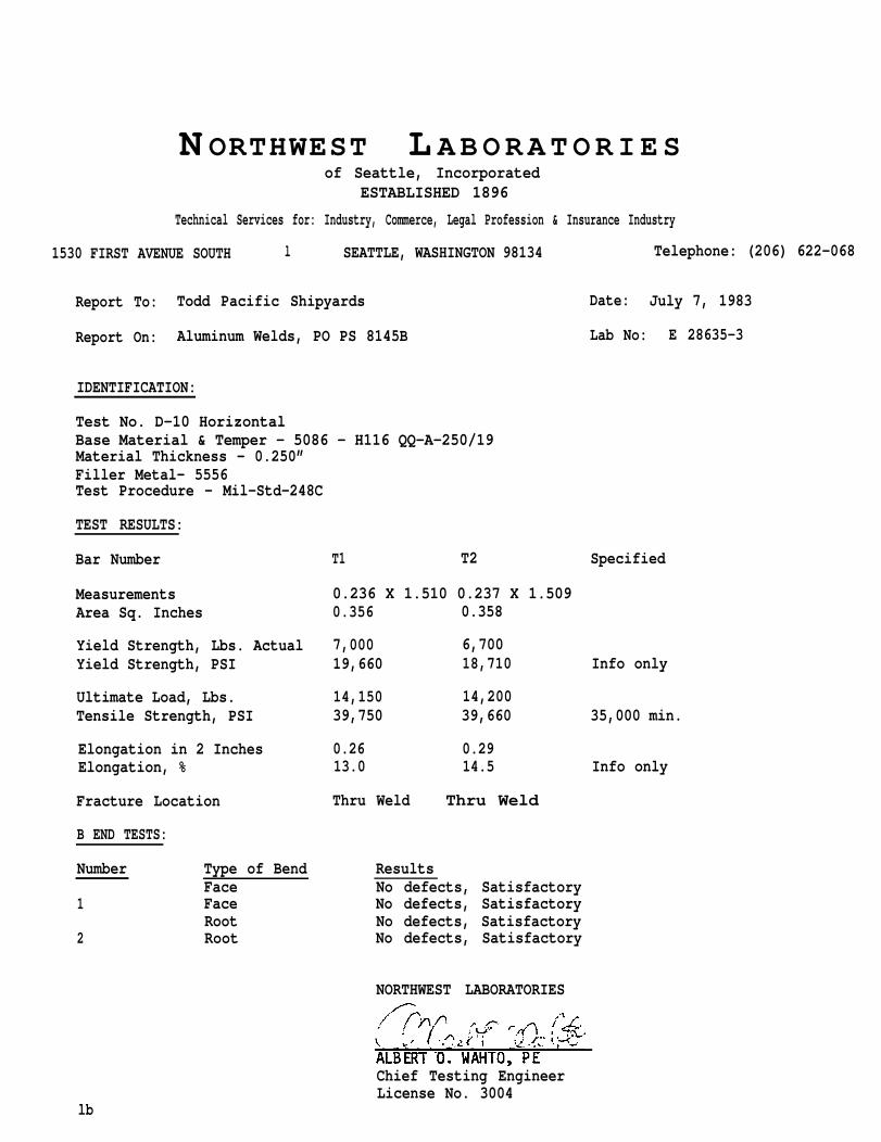
N ORTHWEST L ABORATORIESof Seattle, Incorporated
ESTABLISHED 1896
Technical Services for: Industry, Commerce, Legal Profession & Insurance Industry
1530 FIRST AVENUE SOUTH l SEATTLE, WASHINGTON 98134 Telephone: (206) 622-068
Report To: Todd Pacific Shipyards Date: July 7, 1983
Report On: Aluminum Welds, PO PS 8145B Lab No: E 28635-3
IDENTIFICATION:
Test No. D-10 HorizontalBase Material & Temper - 5086 - H116 QQ-A-250/19Material Thickness - 0.250”Filler Metal- 5556Test Procedure - Mil-Std-248C
TEST RESULTS:
Bar Number T1 T2 Specified
Measurements 0.236 X 1.510 0.237 X 1.509Area Sq. Inches 0.356 0.358
Yield Strength, Lbs. Actual 7,000 6,700Yield Strength, PSI 19,660 18,710 Info only
Ultimate Load, Lbs. 14,150 14,200Tensile Strength, PSI 39,750 39,660 35,000 min.
Elongation in 2 Inches 0.26 0.29Elongation, % 13.0 14.5 Info only
Fracture Location Thru Weld Thru Weld
B END TESTS:
Number Type of Bend ResultsFace No defects, Satisfactory
1 Face No defects, SatisfactoryRoot No defects, Satisfactory
2 Root No defects, Satisfactory
NORTHWEST LABORATORIES
Chief Testing EngineerLicense No. 3004
lb

N ORTHWEST L ABORATORIESof Seattle, Incorporated
ESTABLISHED 1896
Technical Services for: Industry, Commerce. Legal Profession & Insurance Industry
1530 FIRST AVENUE SOUTH l SEAITLE, WASHINGTON 98134 l Telephone: (206) 622-0680
Report To: Todd Pacific Shipyards Date: July 7, 1983
Report On: Aluminum welds, PO PS 8145B Lab No: E 28635-2
IDENTIFICATION:
Test No. E-33 HorizontalBase Material & Temper - 5456 - Hll6 QQ-A-250/7Material Thickness - 0.250”Filler Metal- 5556Test Procedure - Mil-Std-248C
TEST RESULTS:
Bar Number Tl T2
Measurements 0.245 X 1.506 0.246 X 1.506Area Sq. Inches 0.369 0.369
Yield Strength, Lbs. Actual 8,700 9,250Yield Strength, PSI 23,580 25,070
Ultimate Load, Lbs. 15,600 15,800Tensile Strength, PSI 42,280 42,820
elongation in 2 Inches 0.19 0.20Elongation, % 9.5 10.0
Fracture Location Thru Weld Thru Weld
BEND TESTS:
Specified
Info only
42,000 min.
Info only
Number Type of Bend ResultsFace No defects, Satisfactory
1 Face No defects, Satisfactory1 Root No defects, Satisfactory2 Root No defects, Satisfactory
NORTHWEST LABORATORIES
ALBERT O. WAHTO, PEChief Testing EngineerLicense No. 3004
lb
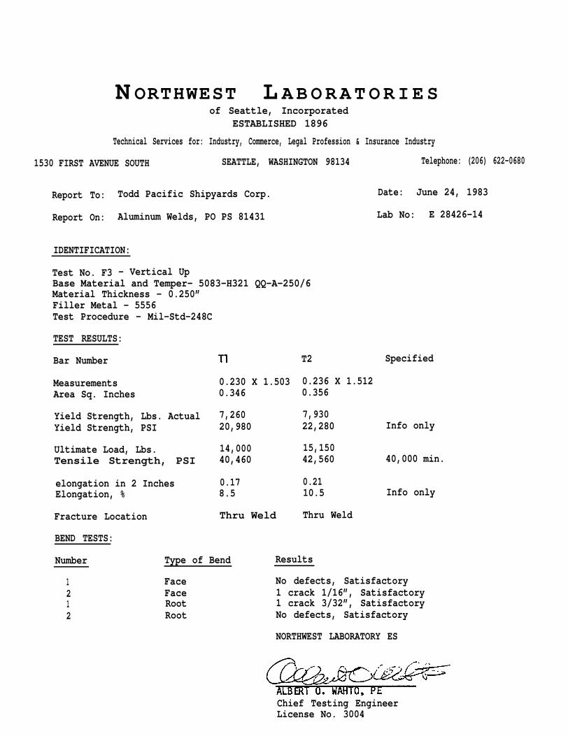
N ORTHWEST L ABORATORIESof Seattle, Incorporated
ESTABLISHED 1896
Technical Services for: Industry, Commerce, Legal Profession & Insurance Industry
1530 FIRST AVENUE SOUTH SEATTLE, WASHINGTON 98134 Telephone: (206) 622-0680
Report To: Todd Pacific Shipyards Corp. Date: June 24, 1983
Report On: Aluminum Welds, PO PS 81431 Lab No: E 28426-14
IDENTIFICATION:
Test No. F3 - Vertical UpBase Material and Temper- 5083-H321 QQ-A-250/6Material Thickness - 0.250”Filler Metal - 5556Test Procedure - Mil-Std-248C
TEST RESULTS:
Bar Number
MeasurementsArea Sq. Inches
Yield Strength, Lbs. ActualYield Strength, PSI
Ultimate Load, Lbs.Tensile Strength, PSI
elongation in 2 InchesElongation, %
Fracture Location
BEND TESTS:
0.230 X 1.5030.346
7,26020,980
14,00040,460
0.178.5
Thru Weld
T2
0.236 X 1.5120.356
Specified
7,93022,280 Info only
15,15042,560 40,000 min.
0.2110.5 Info only
Thru Weld
Number Type of Bend Results
1 Face No defects, Satisfactory2 Face 1 crack 1/16”, Satisfactory1 Root 1 crack 3/32”, Satisfactory2 Root No defects, Satisfactory
NORTHWEST LABORATORY ES
Chief Testing EngineerLicense No. 3004
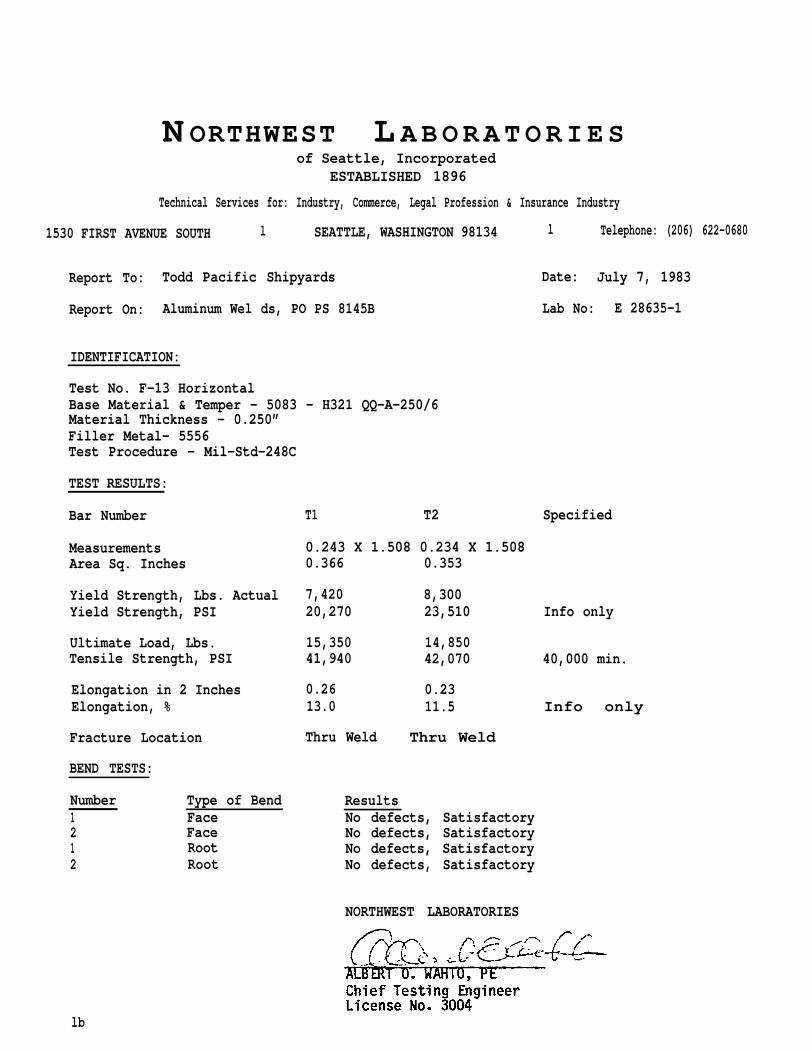
N ORTHWEST L ABORATORIESof Seattle, Incorporated
ESTABLISHED 1896
Technical Services for: Industry, Commerce, Legal Profession & Insurance Industry
1530 FIRST AVENUE SOUTH l SEATTLE, WASHINGTON 98134 l Telephone: (206) 622-0680
Report To: Todd Pacific Shipyards Date: July 7, 1983
Report On: Aluminum Wel ds, PO PS 8145B Lab No: E 28635-1
IDENTIFICATION:
Test No. F-13 HorizontalBase Material & Temper - 5083 - H321 QQ-A-250/6Material Thickness - 0.250”Filler Metal- 5556Test Procedure - Mil-Std-248C
TEST RESULTS:
Bar Number
MeasurementsArea Sq. Inches
Yield Strength, Lbs. ActualYield Strength, PSI
Ultimate Load, Lbs.Tensile Strength, PSI
Elongation in 2 InchesElongation, %
Fracture Location
BEND TESTS:
Number Type of Bend1 Face2 Face1 Root2 Root
T1 T2
0.243 X 1.508 0.234 X 1.5080.366 0.353
Specified
7,420 8,30020,270 23,510 Info only
15,350 14,85041,940 42,070 40,000 min.
0.26 0.2313.0 11.5 Info only
Thru Weld Thru Weld
ResultsNo defects, SatisfactoryNo defects, SatisfactoryNo defects, SatisfactoryNo defects, Satisfactory
NORTHWEST LABORATORIES
lb
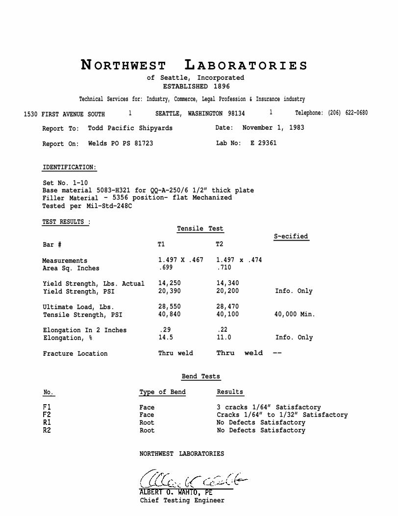
N ORTHWEST L ABORATORIESof Seattle, Incorporated
ESTABLISHED 1896
Technical Services for: Industry, Commerce, Legal Profession & Insurance industry
1530 FIRST AVENUE SOUTH l SEATTLE, WASHINGTON 98134 l Telephone: (206) 622-0680
Report To: Todd Pacific Shipyards Date: November 1, 1983
Report On: Welds PO PS 81723 Lab No: E 29361
IDENTIFICATION:
Set No. 1-10Base material 5083-H321 for QQ-A-250/6 1/2” thick plateFiller Material - 5356 position- flat Mechanized Tested per Mil-Std-248C
TEST RESULTS :
Bar #
MeasurementsArea Sq. Inches
Yield Strength, Lbs. ActualYield Strength, PSI
Ultimate Load, Lbs.Tensile Strength, PSI
Elongation In 2 InchesElongation, %
Fracture Location
No.
Tensile Test
T1 T2
1.497 X .467 1.497.699 .710
S~ecified
x .474
14,250 14,34020,390 20,200 Info. Only
28,550 28,47040,840 40,100 40,000 Min.
.29 .2214.5 11.0 Info. Only
Thru weld Thru weld --
Bend Tests
Type of Bend Results
Face 3 cracks 1/64” SatisfactoryFace Cracks 1/64” to 1/32” SatisfactoryRoot No Defects SatisfactoryRoot No Defects Satisfactory
NORTHWEST LABORATORIES
Chief Testing Engineer
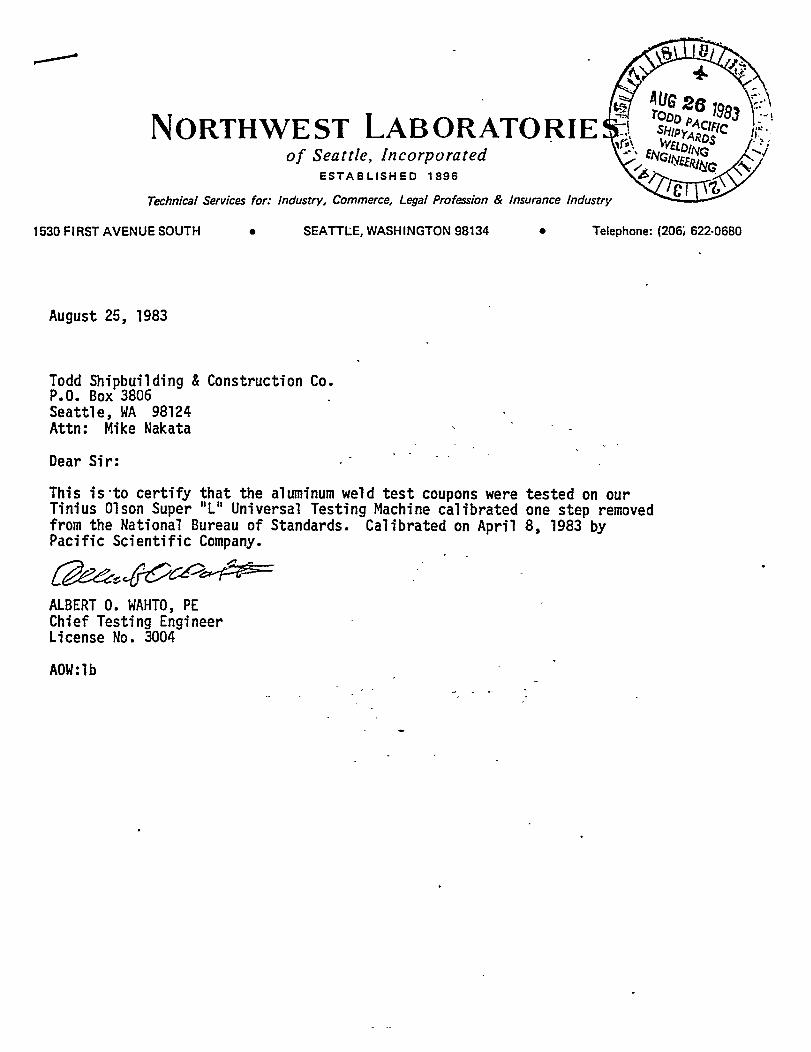
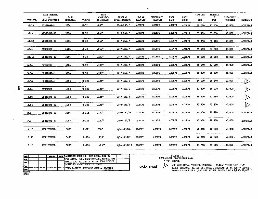
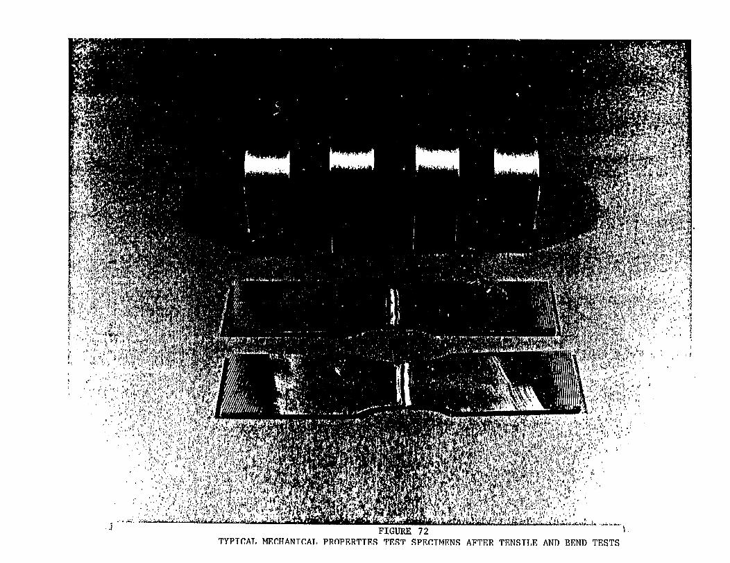
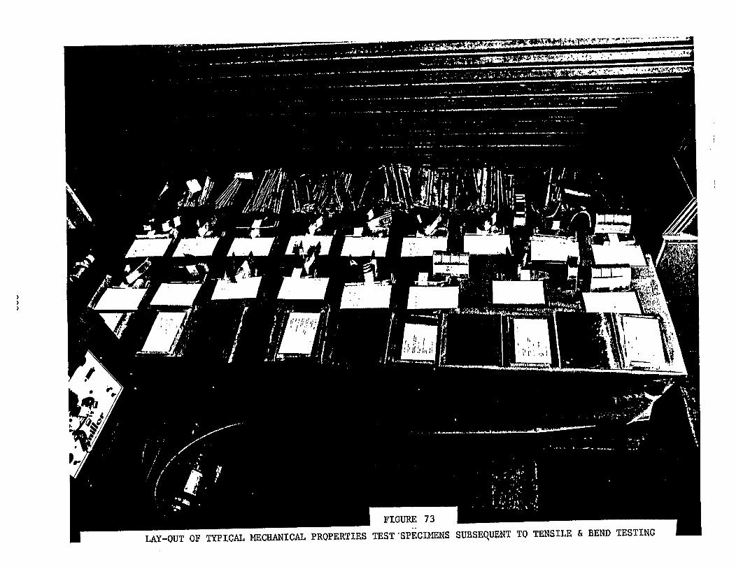
PULSE ARC WELDING MACHINE SETTINGS
Pulse arc welding machine settings that were determined and established
during this program are shown in a summary page form and also in indivi-
dual machine setting forms. These machine settings represent actual
values developed during the course of this investigation and apply
primarily to butt welding in the out-of-position, one-side, full pene-
tration manual gas metal arc welding of 5000 series aluminum alloy sheet
and plates. These values provide excellent starting weld parameters
and should be adjusted accordingly for other weld joint designs and other
marine aluminum alloys.
Charts showing wire feed speeds (inches per minute) vs. wire speed dial
settings have been developed for the Airco System 1, Airco AHF-NP,
Gilliland MTG 4001 and the M & K wire feeders. It is anticipated that
these charts would be helpful in the developmental determination of
individual machine settings.
The following information covering pulse arc welding machine settings
are divided into three sections: Airco PA-3A & PA-350, Gilliland CV-
600 FI-PA, and the Miller Pulstar 450. Each
matrix of machine settings, wire feed speeds
individually developed detailed weld machine
section includes a
vs. dial settings and
settings.
221
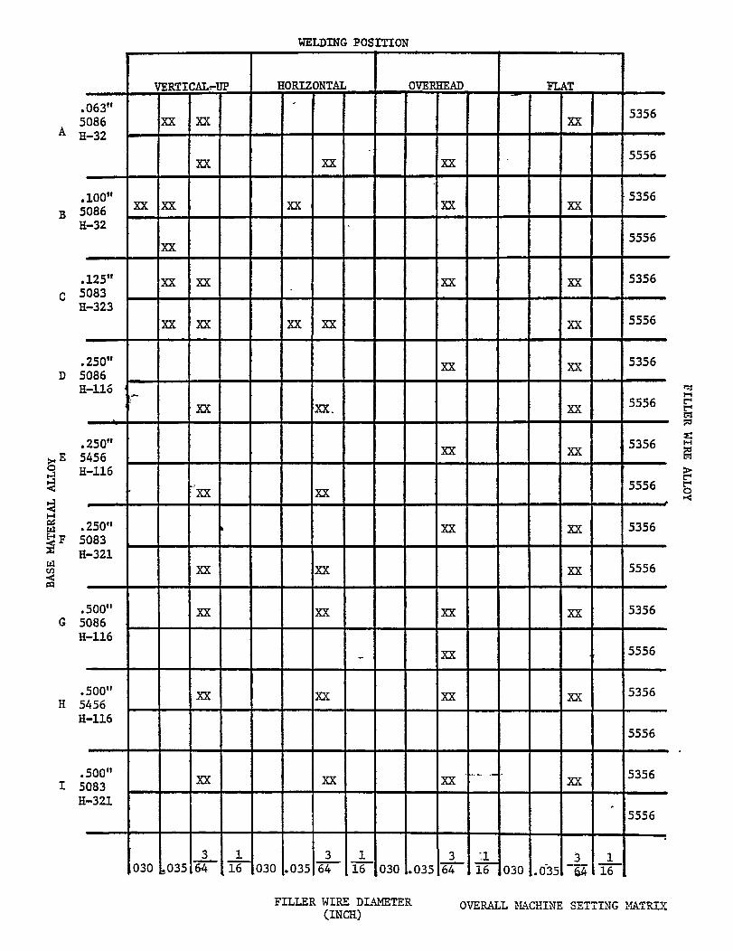
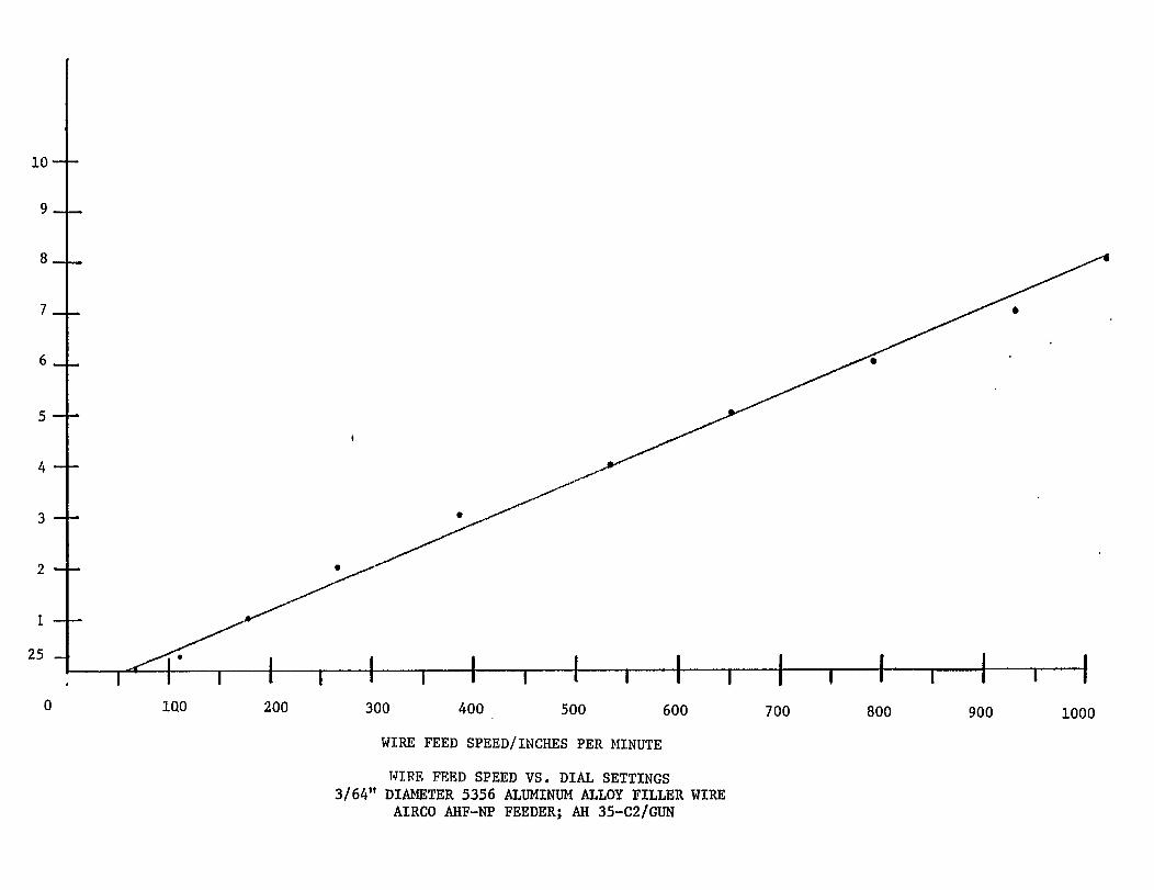
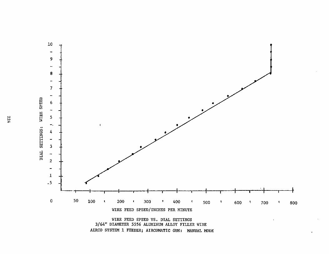
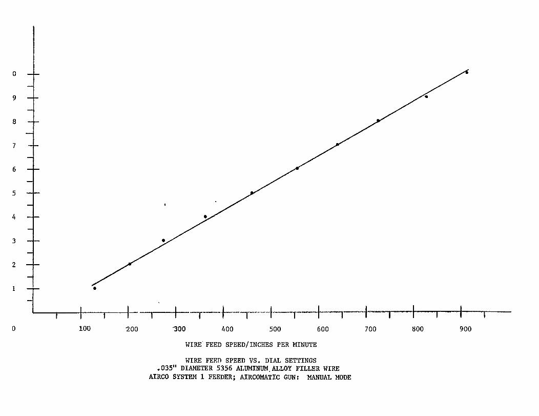
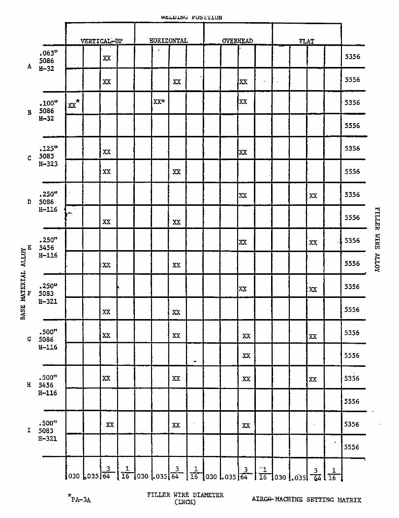
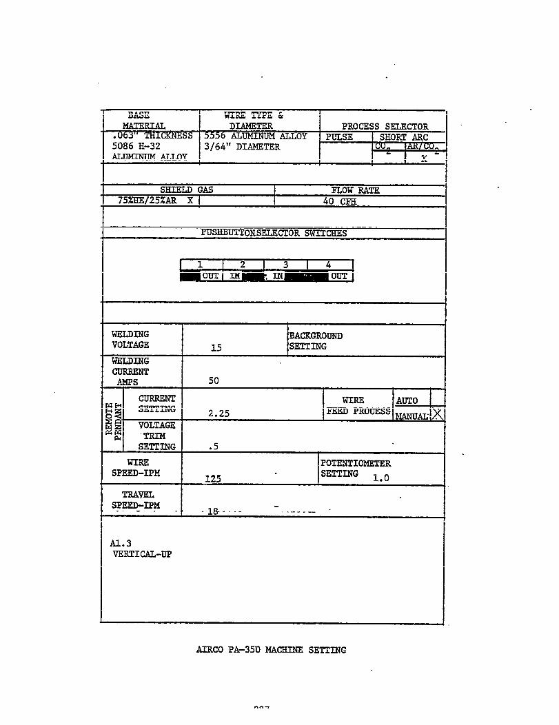

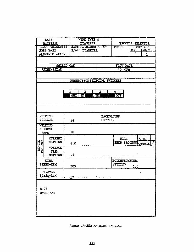


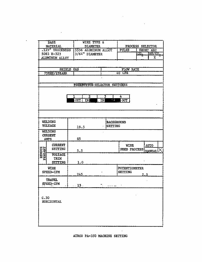
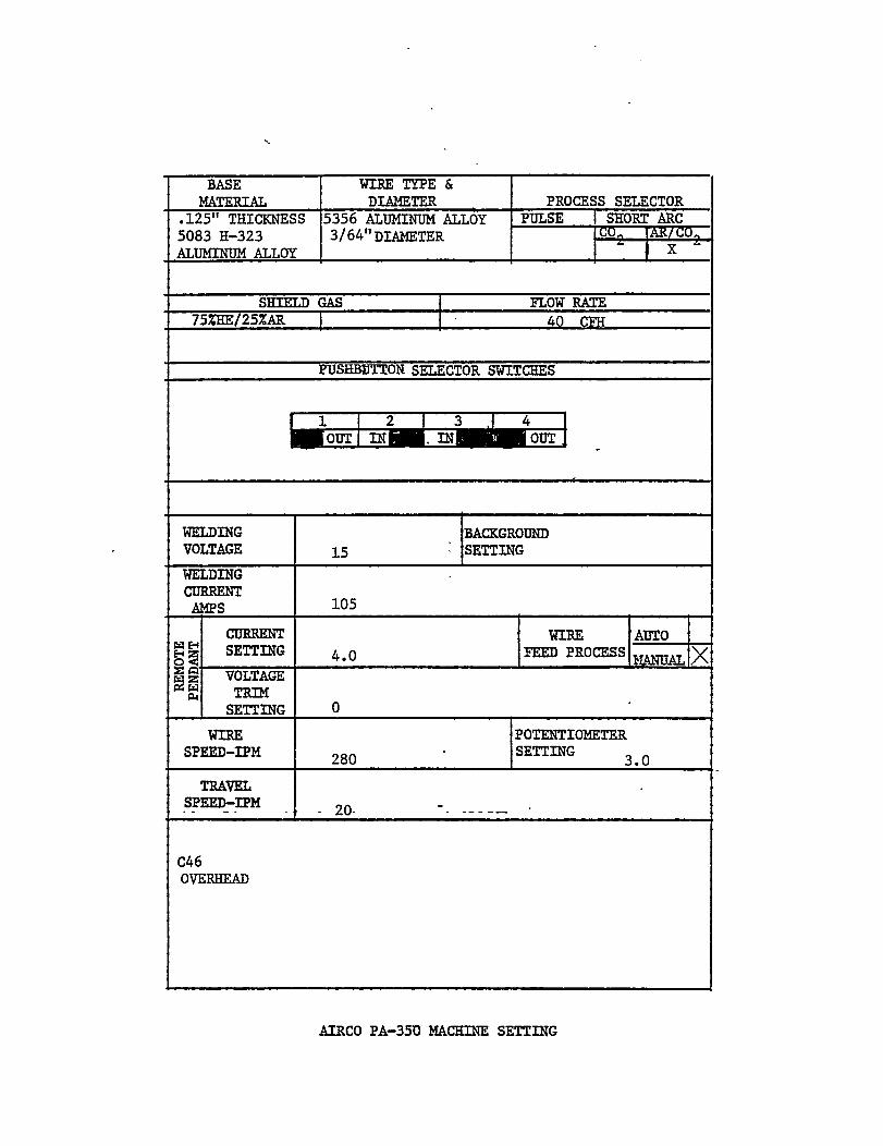
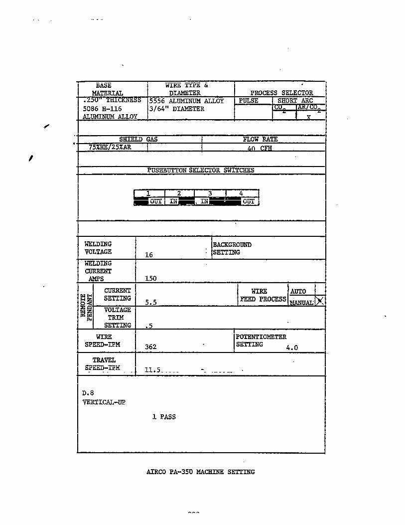
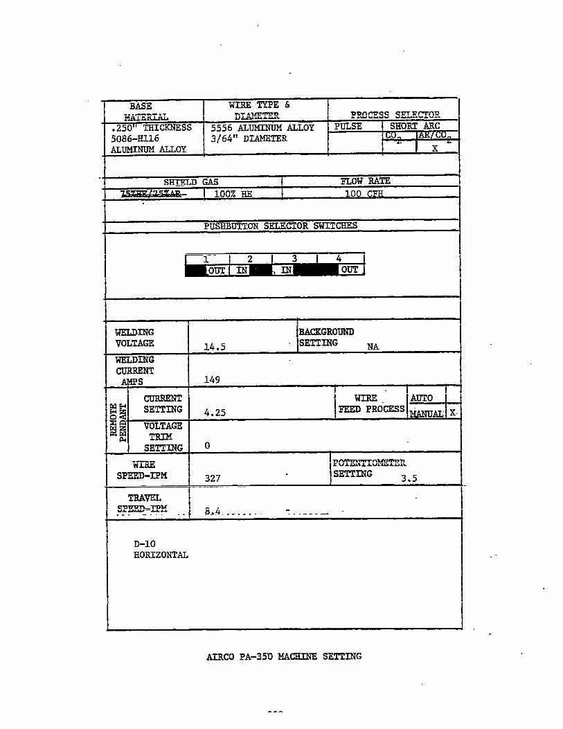
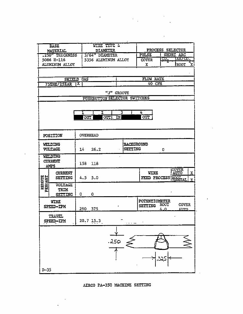
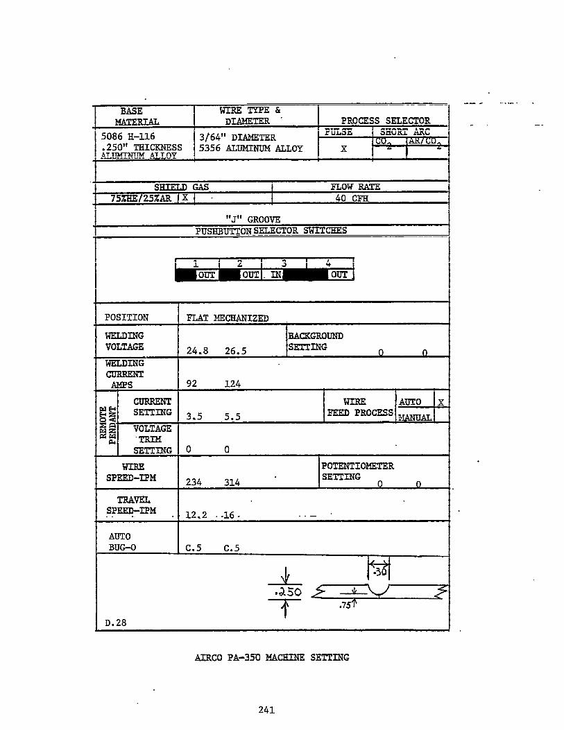
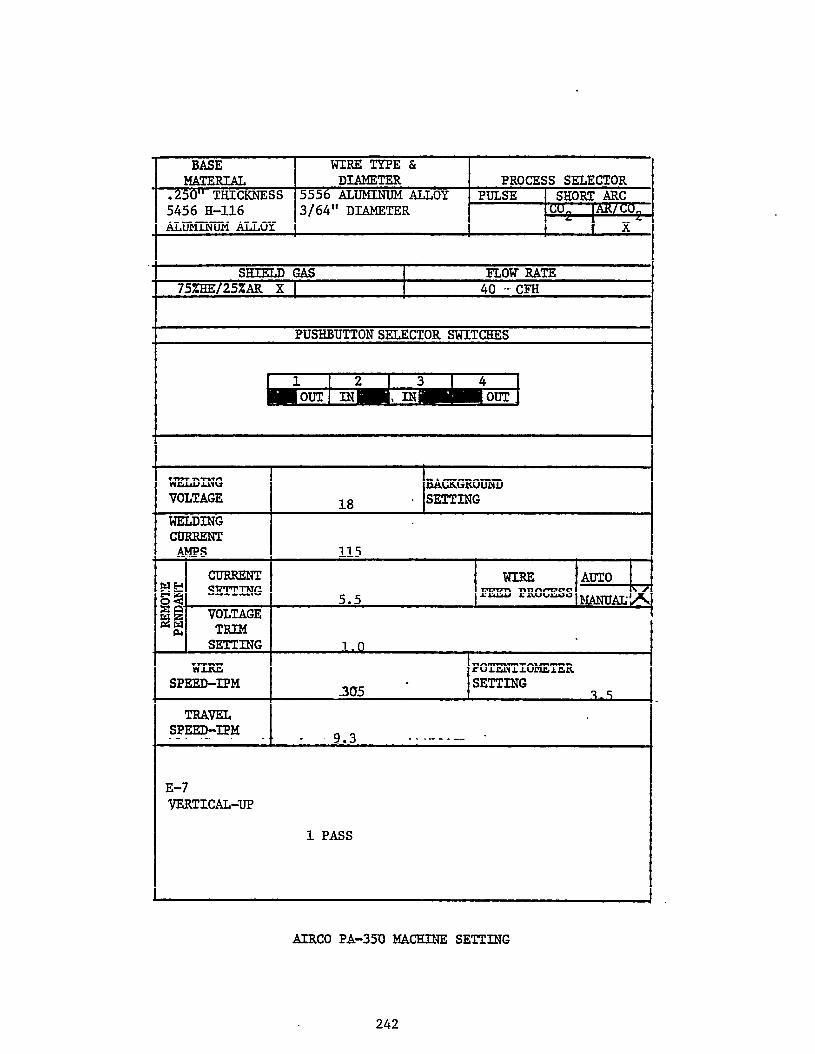
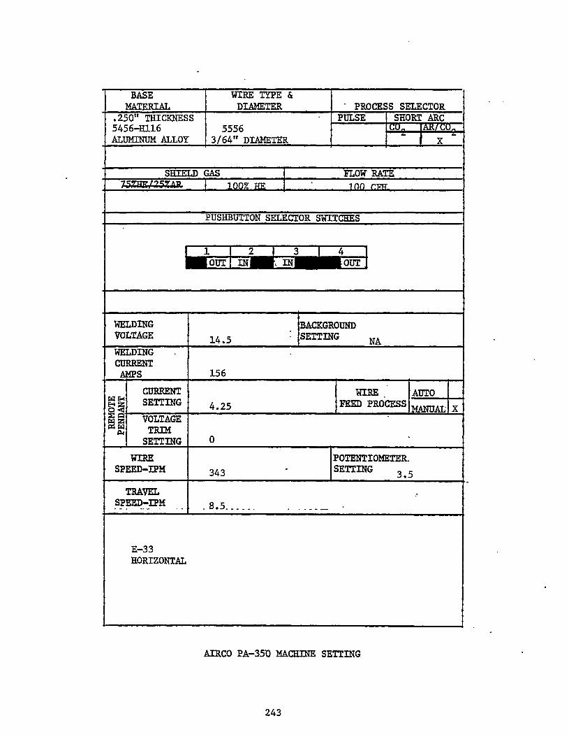
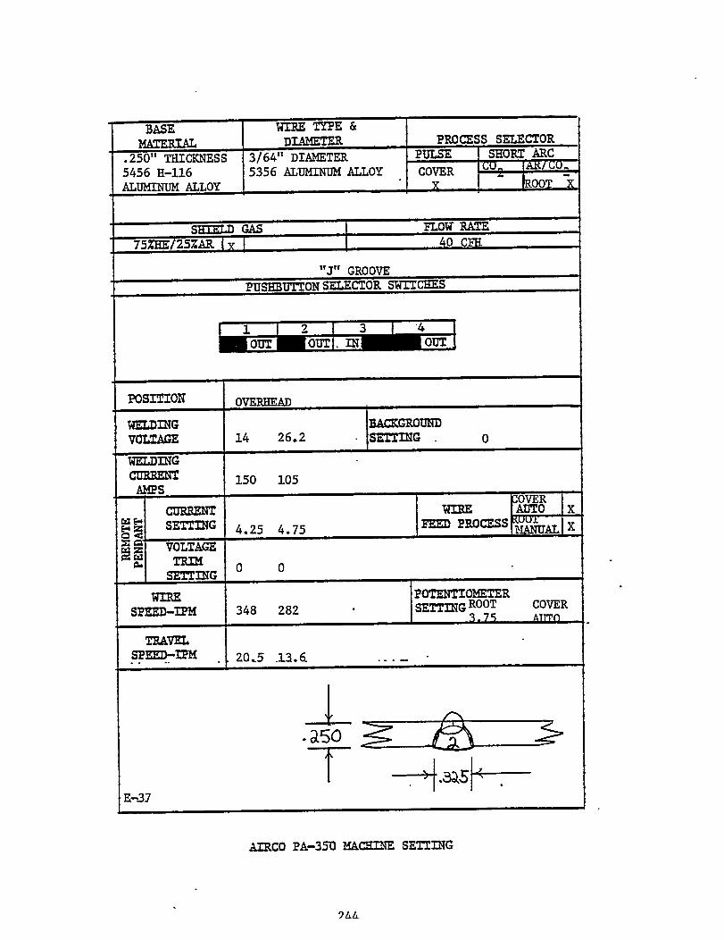
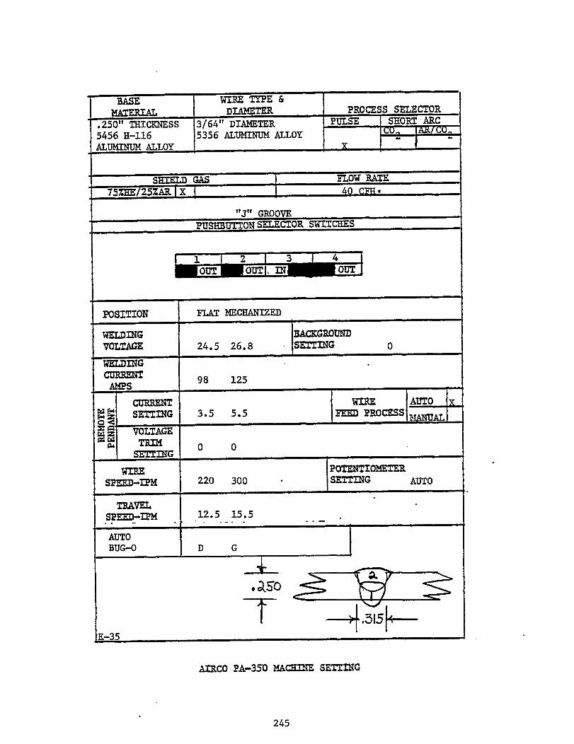
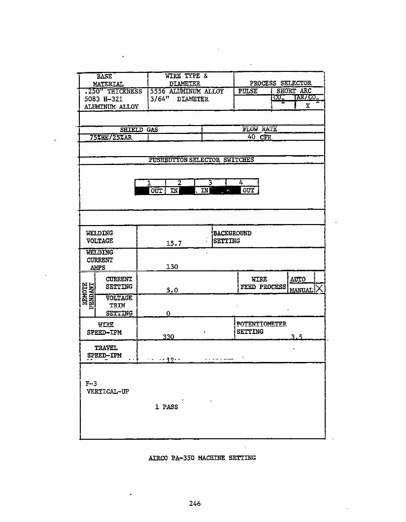
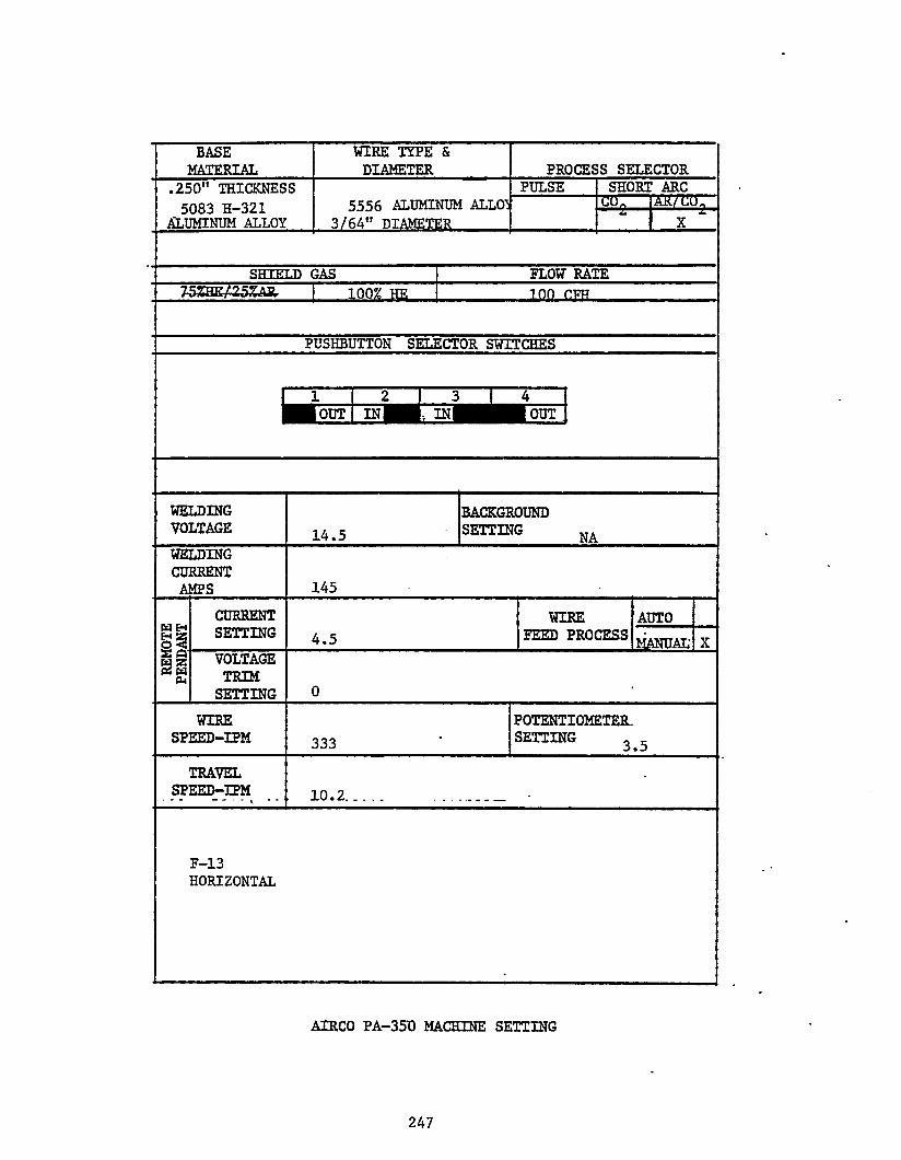
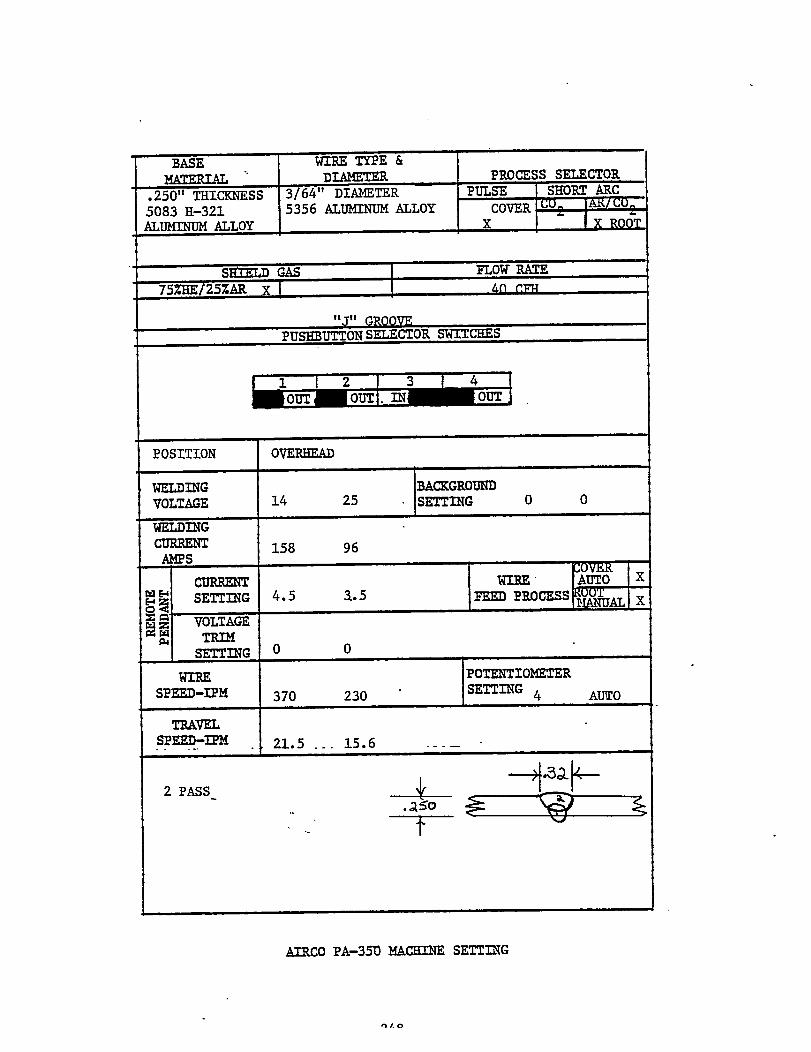

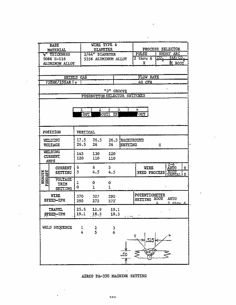
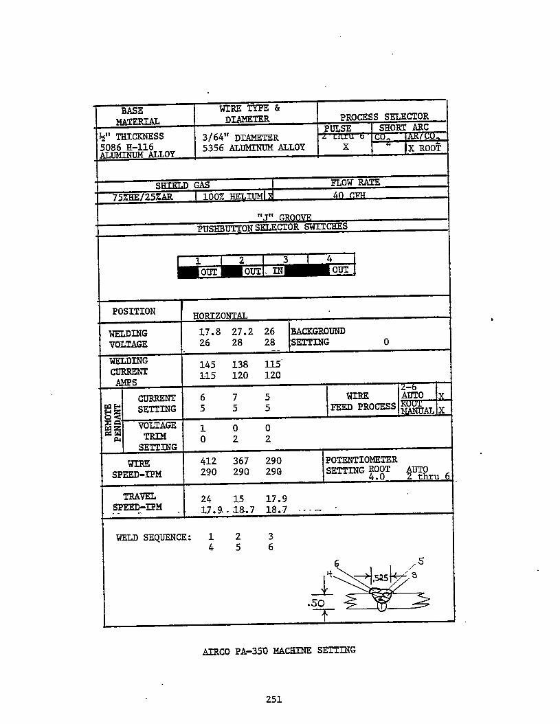
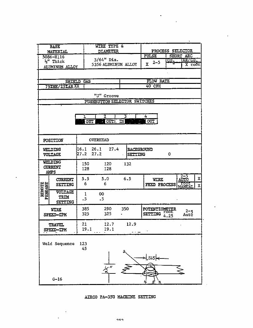
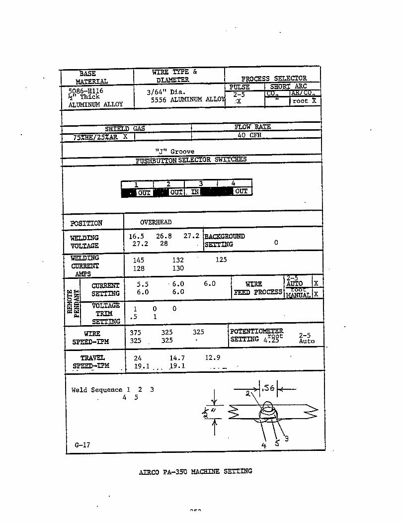
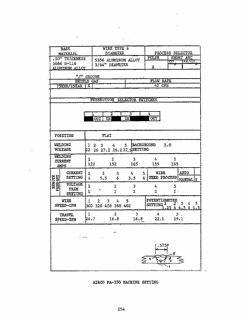
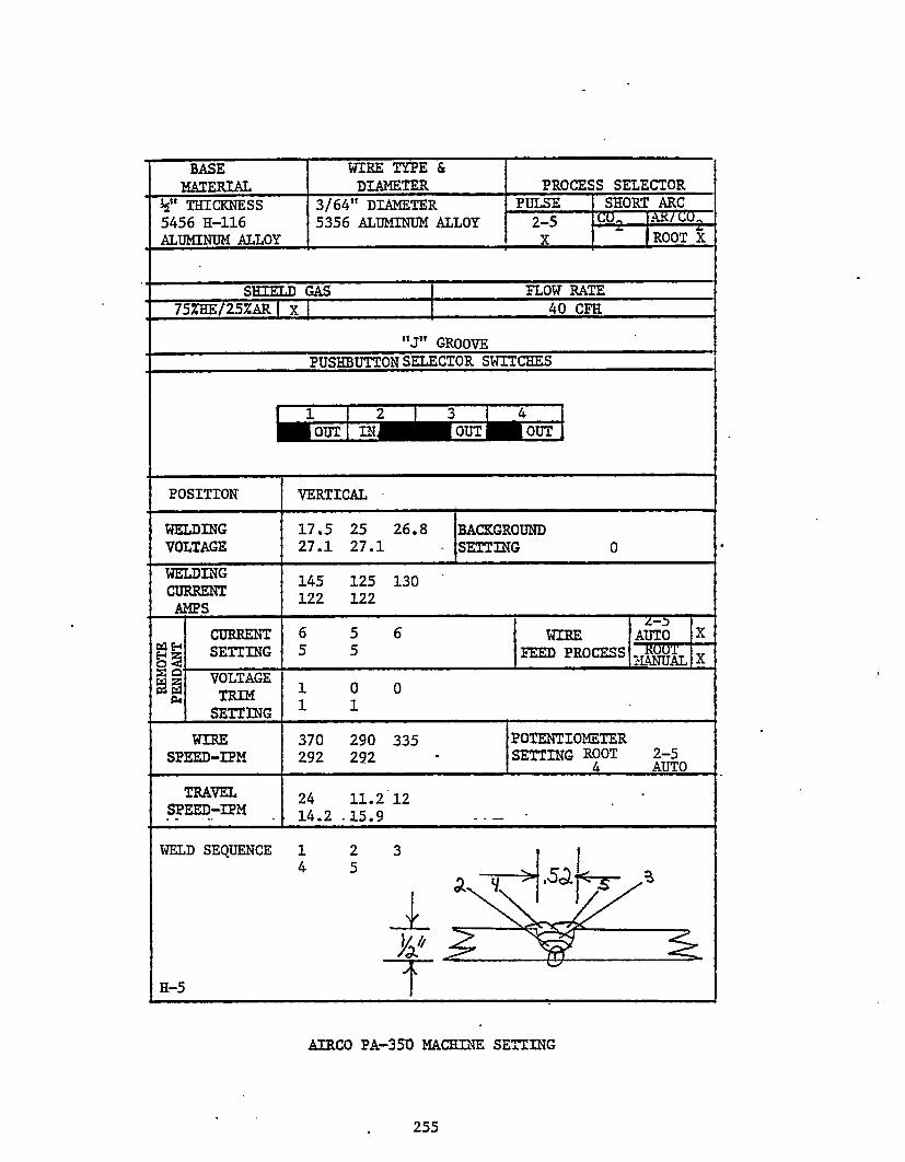
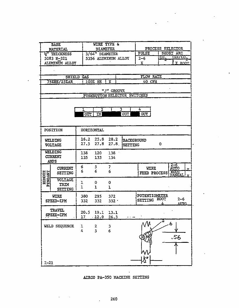
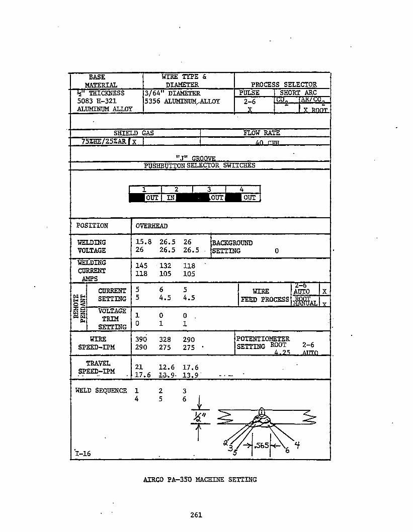
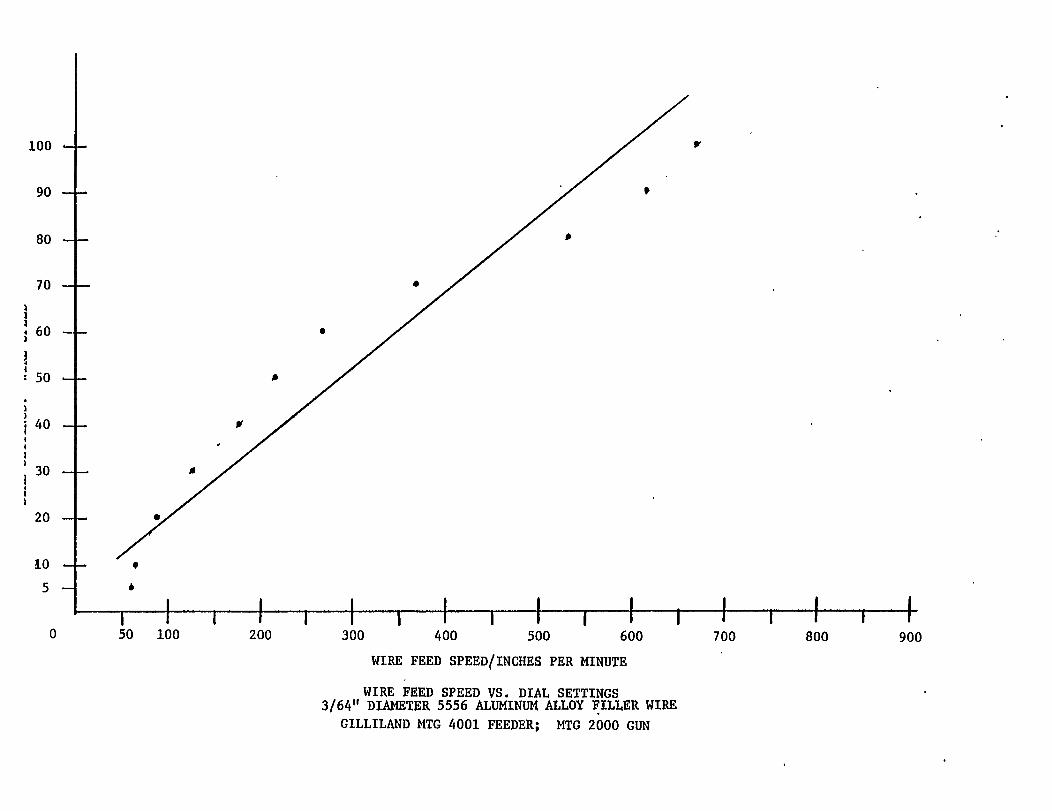
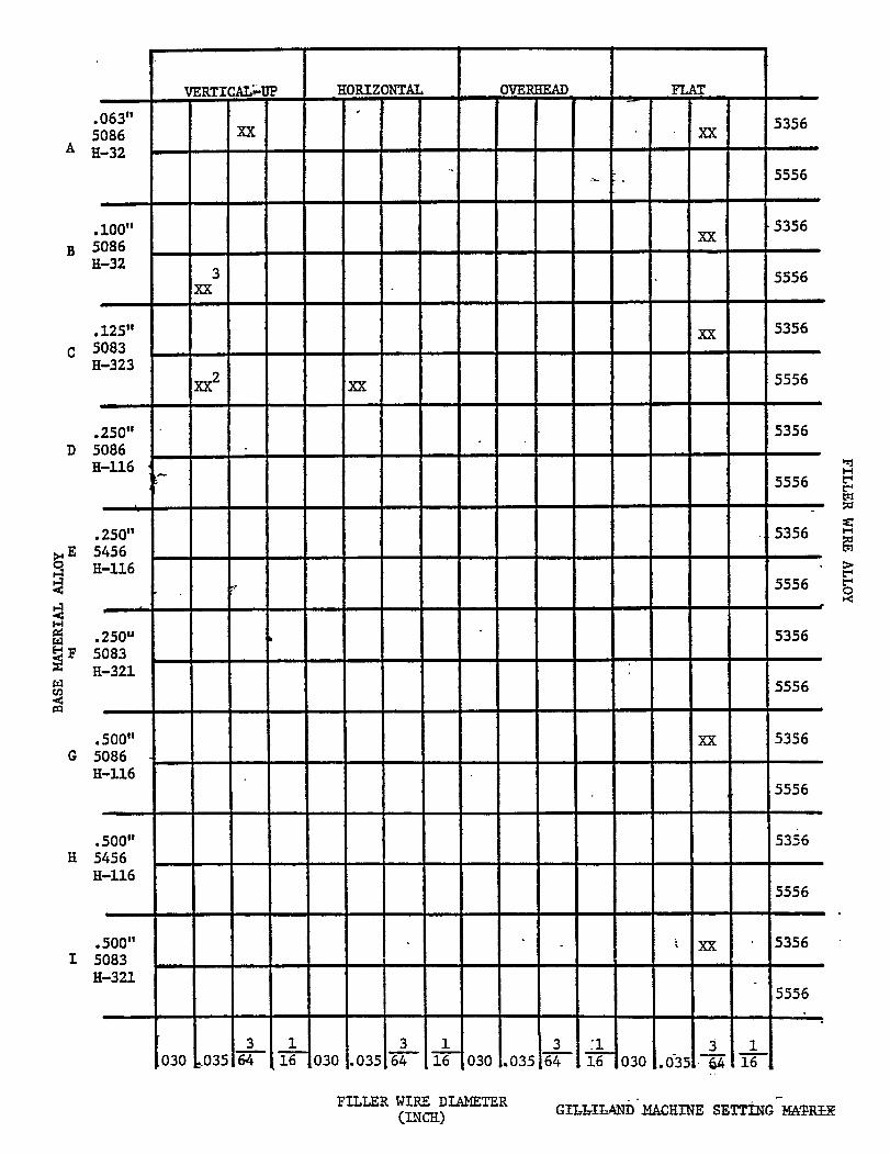
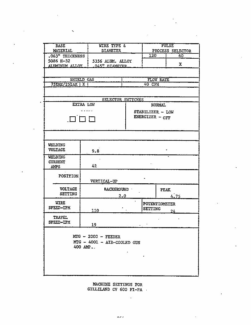
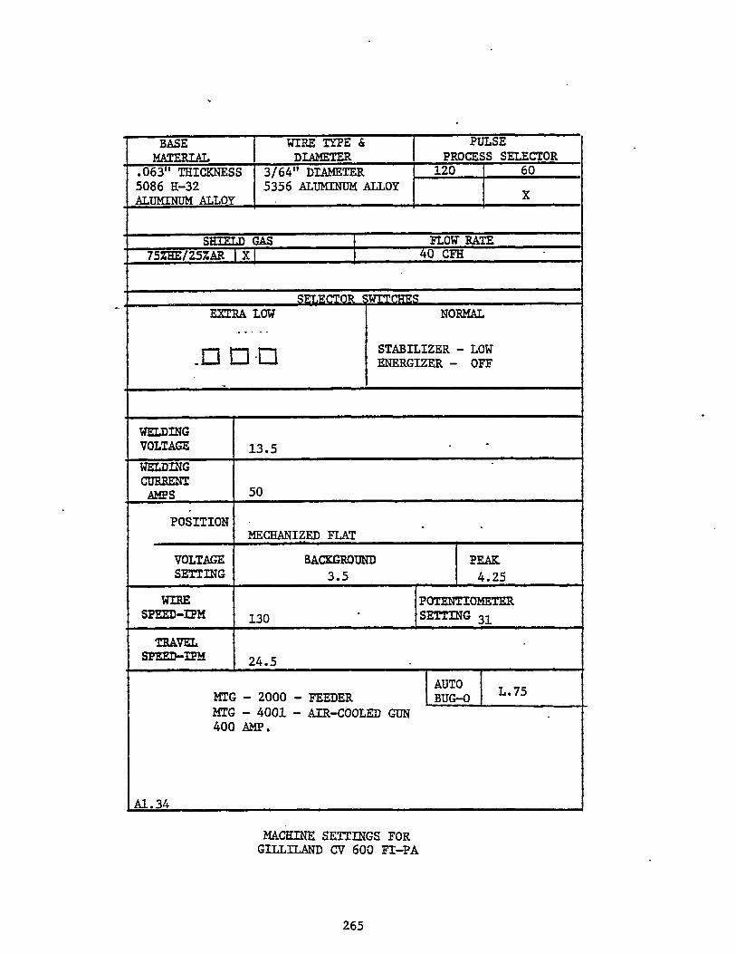
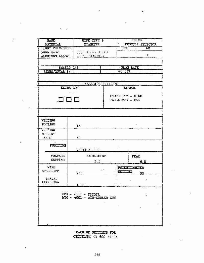
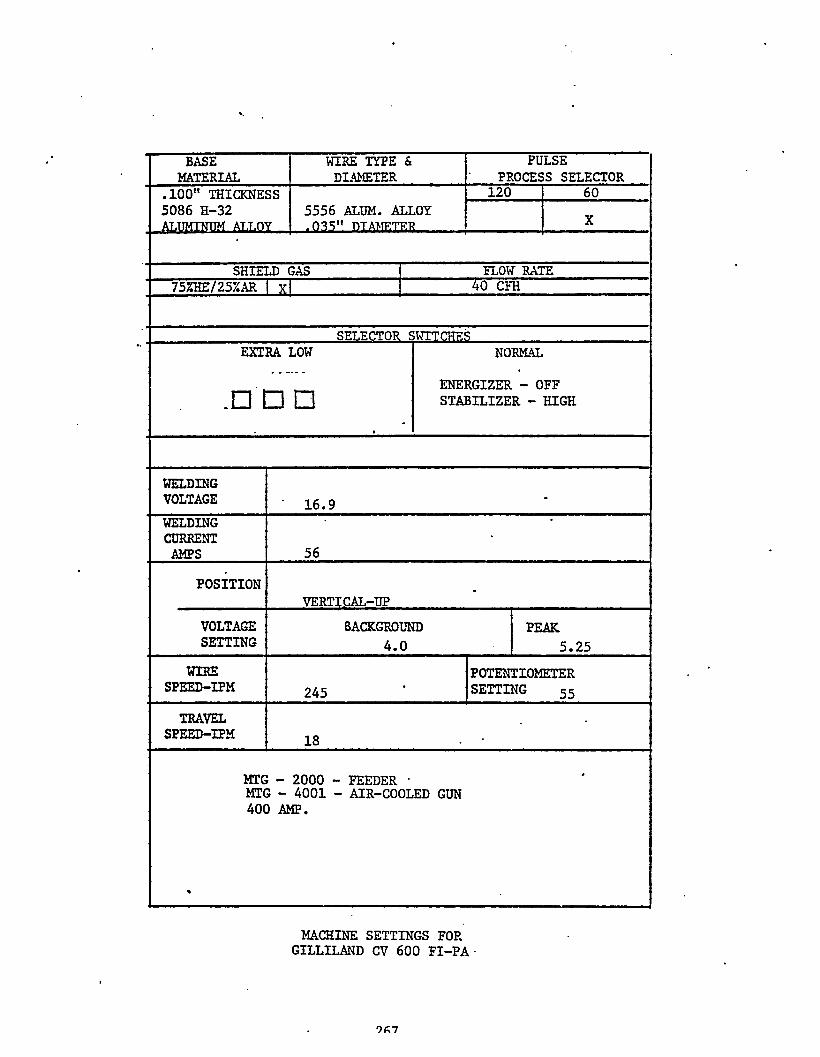
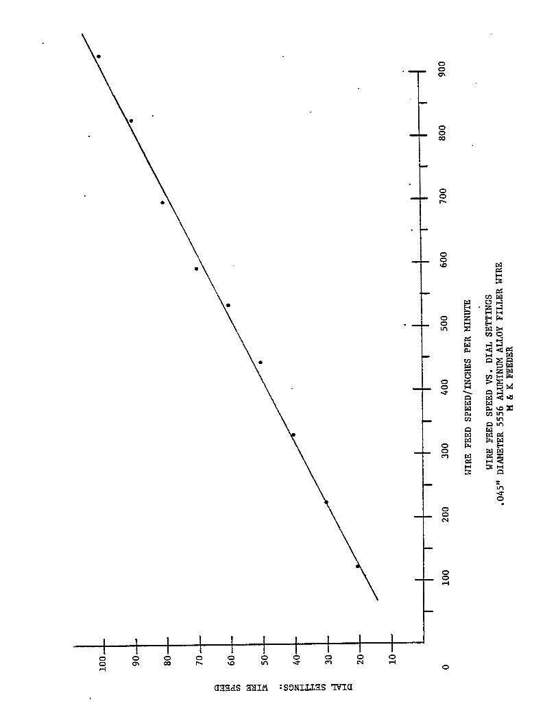
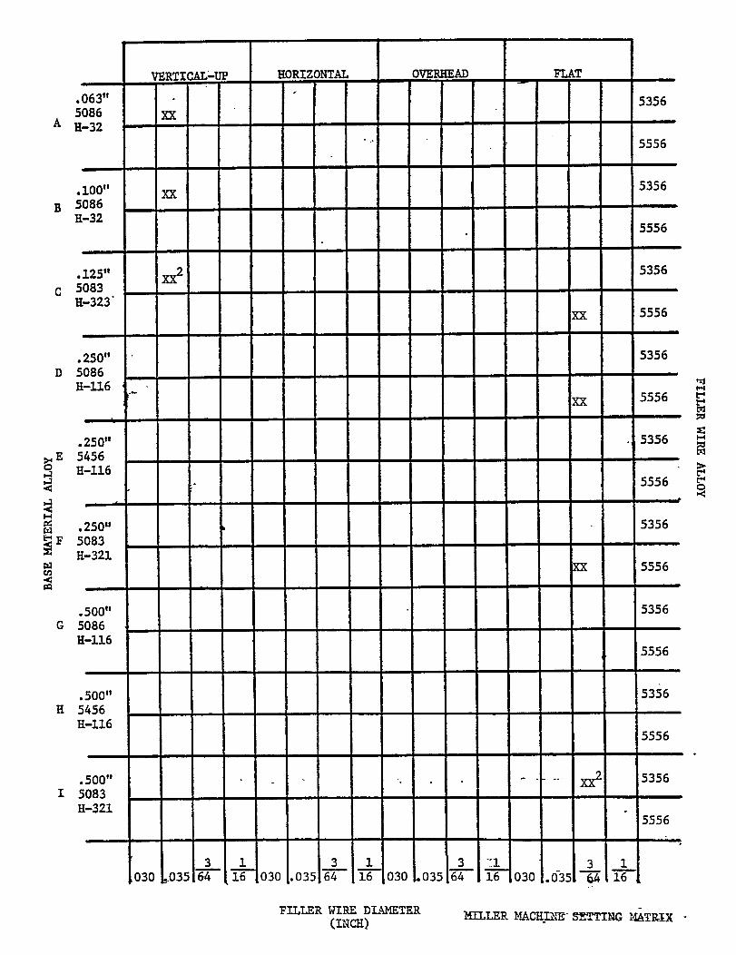
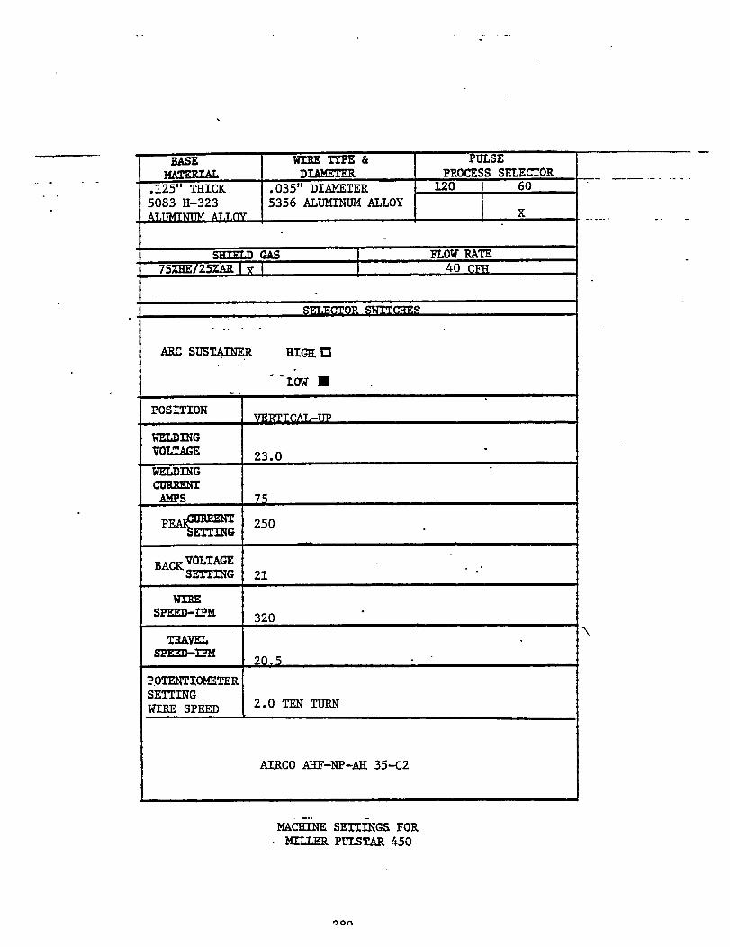
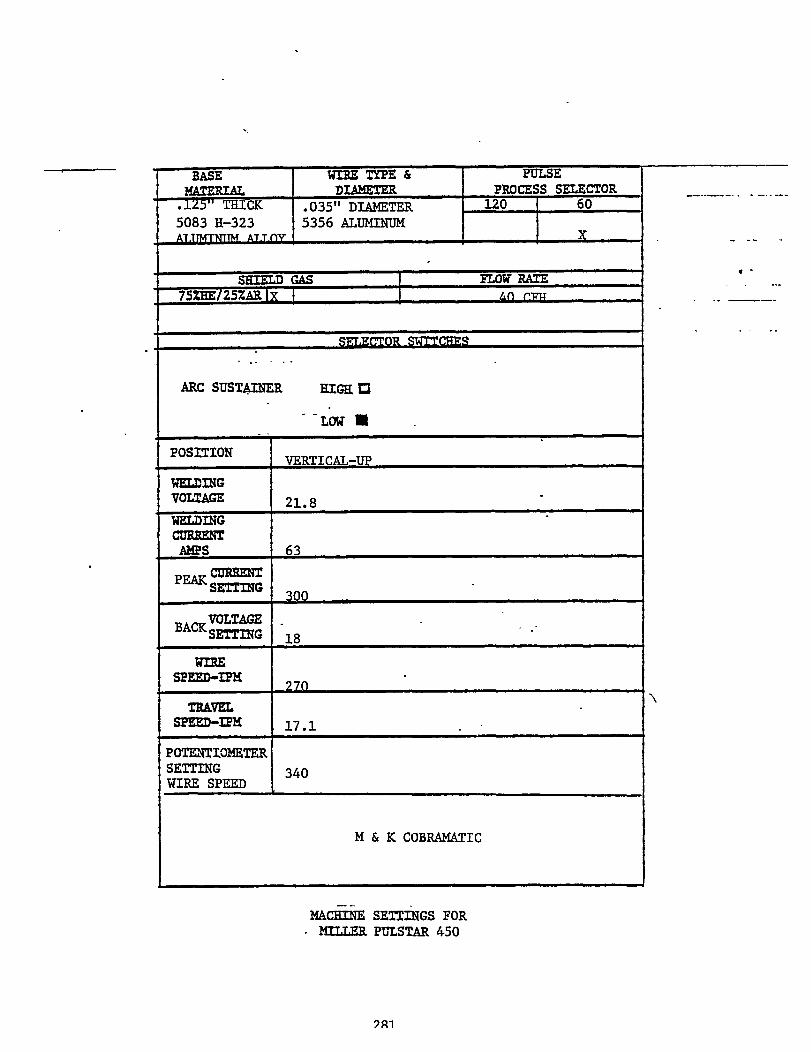
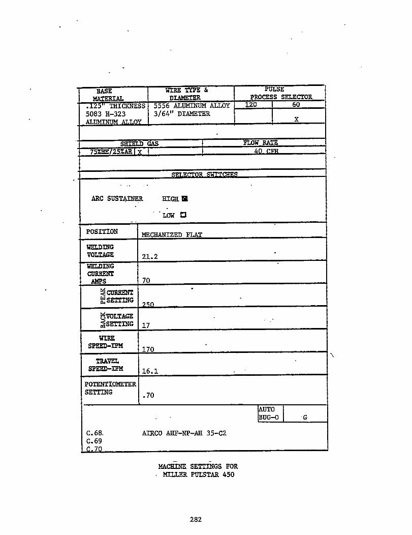
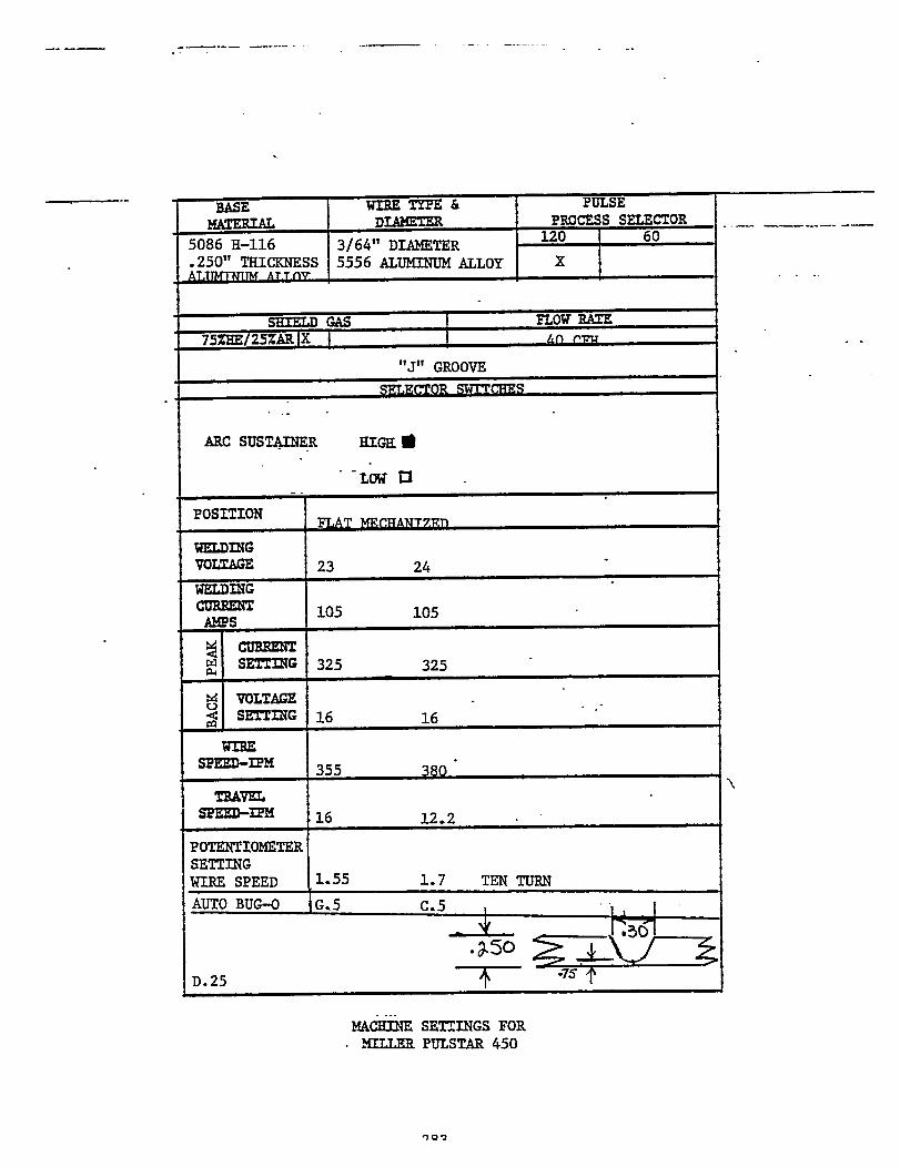
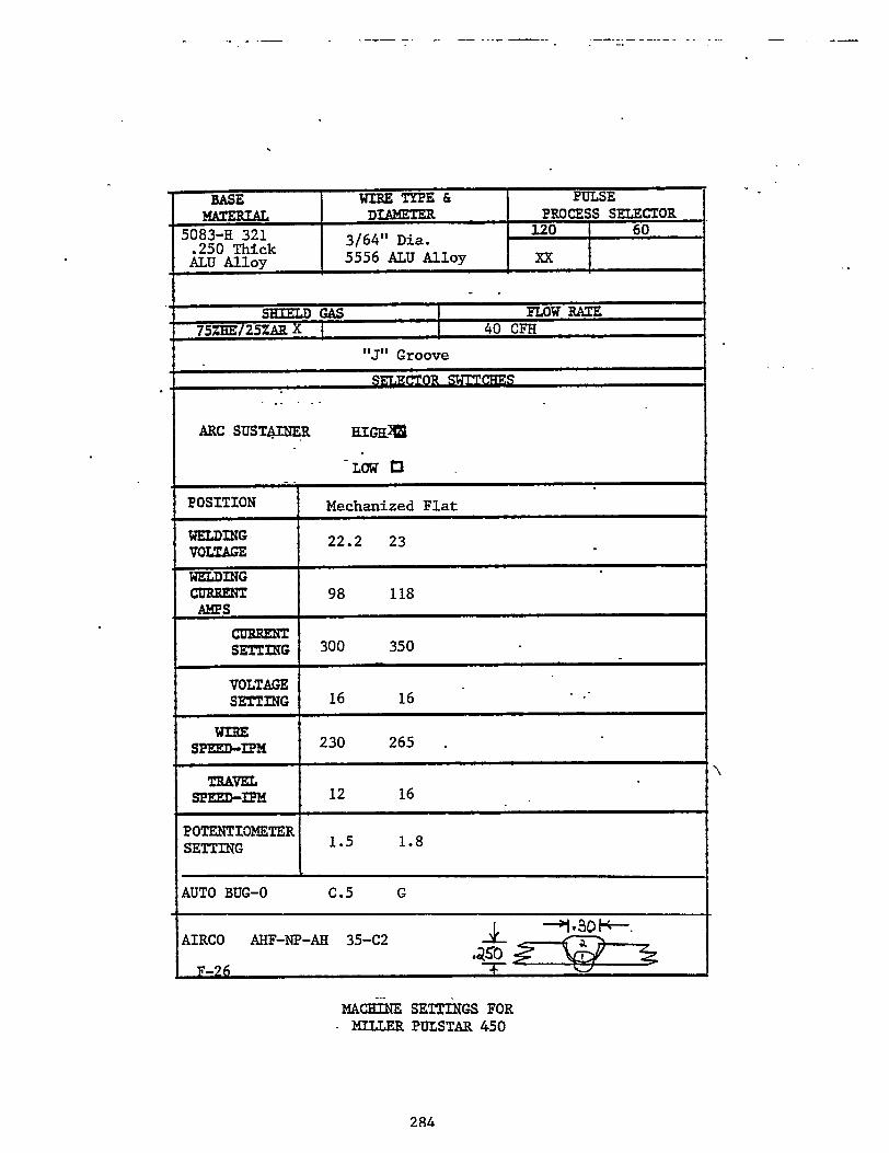
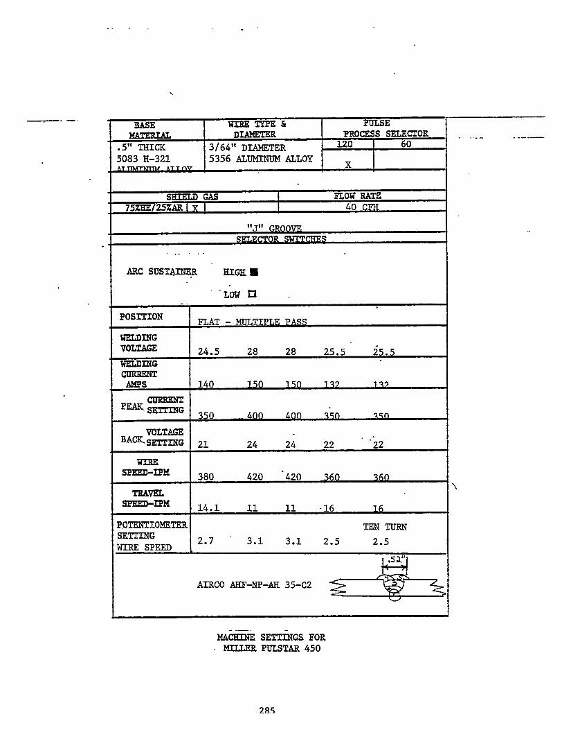
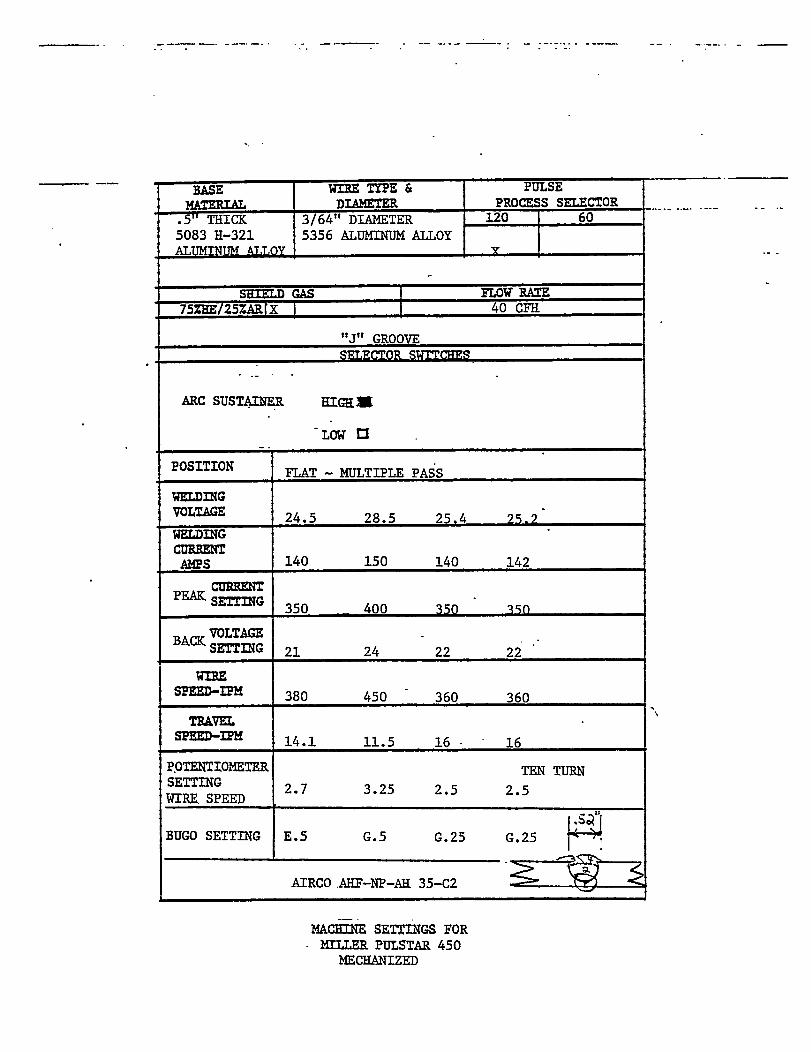
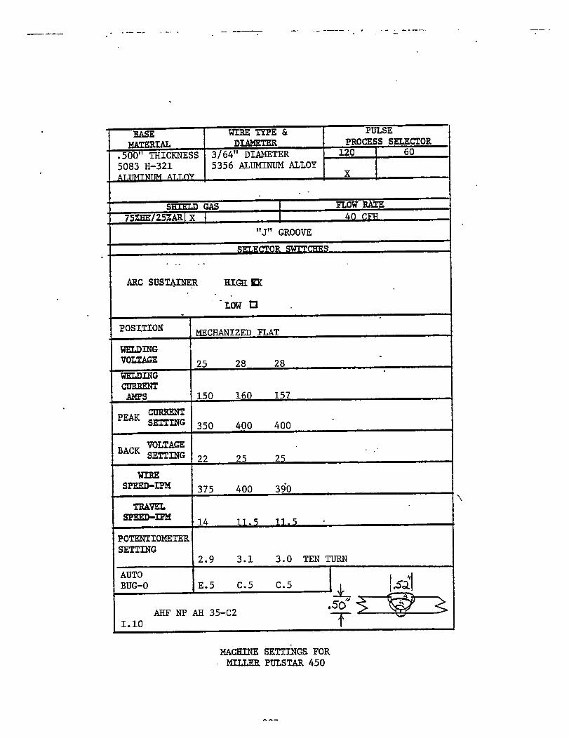

WELDING PROCEDURE SPECIFICATION(GUIDE)
ALUMINUM WELDING
OUT-OF-POSITION WELDING OF 5000ALLOYS USING GMAW POWER
SERIES ALUMINUMSOURCES
289

1. SCOPE
This welding procedure covers the requirements for out-of-position,
one-side, full penetration, manual pulse gas metal arc butt welding
of the 5000 series aluminum alloys. This procedure is applicable
to material thicknesses of .063 inch to .500 inch.

2. TABLE OF CONTENTS
1. Scope
2. Table of Contents
3. References
4. Material Control
4.1 Base Material
4.2 Filler Metals
5. Shielding Gases
6. Electrical Characteristics
7. Position of Welding
8. Facilities Control
9. Procedure Qualification & Welder PerformanceQualification
10. Manufacturing Control
10.1 Joint Design and Tolerance
10.2 Material Preparation
10.3 Weld Joint Fit-Up
10.4 Preheat and Interpass
10.5 Tack Welding
10.6 Welding Techniques
Temperatures
10.7 Repair Welds
10.8 Post-Weld Heat
10.9 Peening
11. Quality Assurance
Treatment
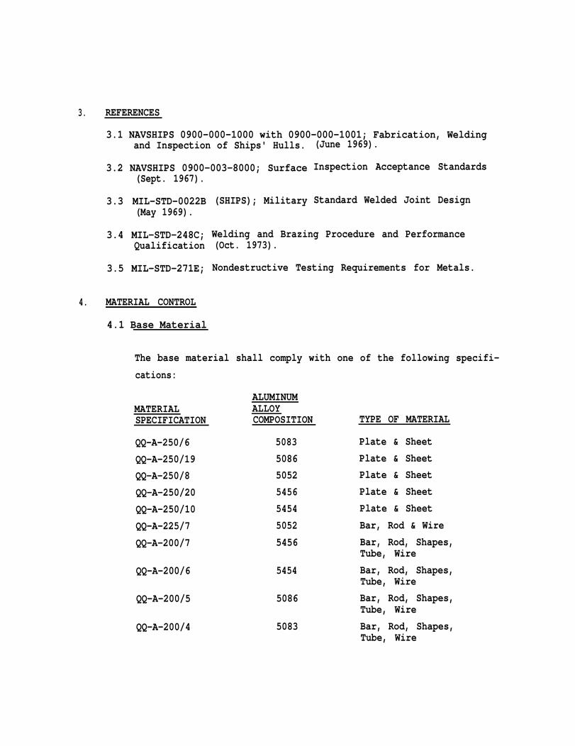
3. REFERENCES
3.1 NAVSHIPS 0900-000-1000 with 0900-000-1001; Fabrication, Weldingand Inspection of Ships' Hulls.
3.2 NAVSHIPS 0900-003-8000; Surface(Sept. 1967).
3.3 MIL-STD-0022B(May 1969).
3.4 MIL-STD-248C;Qualification
3.5 MIL-STD-271E;
4. MATERIAL CONTROL
4.1 Base Material
(SHIPS); Military
(June 1969).
Inspection Acceptance Standards
Standard Welded Joint Design
Welding and Brazing Procedure and Performance(Oct. 1973).
Nondestructive Testing Requirements for Metals.
The base material shall comply with one of the following specifi-
cations:
MATERIALSPECIFICATION
QQ-A-250/6
QQ-A-250/19
QQ-A-250/8
QQ-A-250/20
QQ-A-250/10
QQ-A-225/7
QQ-A-200/7
QQ-A-200/6
QQ-A-200/5
QQ-A-200/4
ALUMINUMALLOYCOMPOSITION
5083
5086
5052
5456
5454
5052
5456
5454
5086
5083
TYPE OF MATERIAL
Plate & Sheet
Plate & Sheet
Plate & Sheet
Plate & Sheet
Plate & Sheet
Bar, Rod & Wire
Bar, Rod, Shapes,Tube, Wire
Bar, Rod, Shapes,Tube, Wire
Bar, Rod, Shapes,Tube, Wire
Bar, Rod, Shapes,Tube, Wire
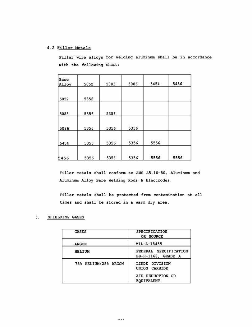
4.2 Filler Metals
Filler wire alloys
with the following
for welding aluminum shall be in accordance
chart:
BaseAlloy 5052 5083 5086 5454 5456
5052 5356
5083 5356 5356
5086 5356 5356 5356
5454 5356 5356 5356 5556
5456 5356 5356 5356 5556 5556
Filler metals shall conform to AWS A5.10-80, Aluminum and
Aluminum Alloy Bare Welding Rods & Electrodes.
Filler metals shall be protected from contamination at all
times and shall be stored in a warm dry area.
5. SHIELDING GASES
GASES SPECIFICATIONOR SOURCE
ARGON MIL-A-18455
HELIUM FEDERAL SPECIFICATIONBB-H-1168, GRADE A
75% HELIUM/25% ARGON LINDE DIVISIONUNION CARBIDE
AIR REDUCTION OREQUIVALENT
293
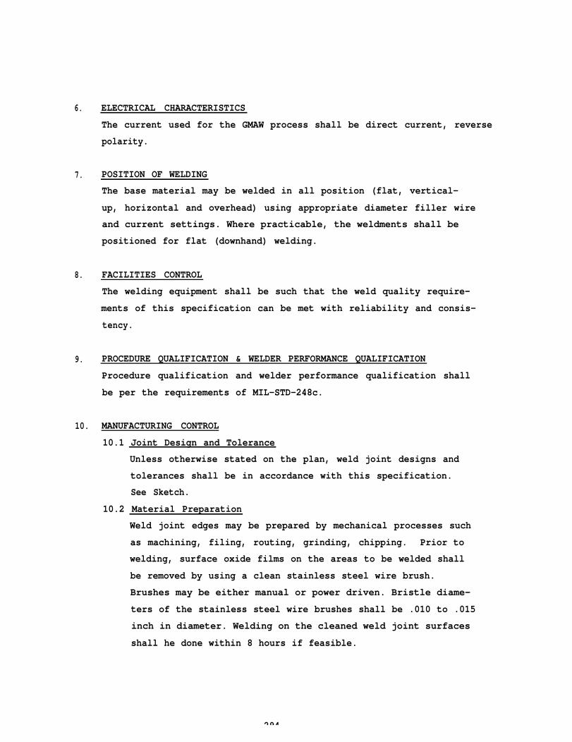
6.
7.
8.
9.
ELECTRICAL CHARACTERISTICS
The current used for the GMAW process shall be direct current, reverse
polarity.
POSITION OF WELDING
The base material may be welded in all position (flat, vertical-
up, horizontal and overhead) using appropriate diameter filler wire
and current settings. Where practicable, the weldments shall be
positioned for flat (downhand) welding.
FACILITIES CONTROL
The welding equipment shall be such that the weld quality require-
ments of this specification can be met with reliability and consis-
tency.
PROCEDURE QUALIFICATION & WELDER PERFORMANCE QUALIFICATION
Procedure qualification and welder performance qualification shall
be per the requirements of MIL-STD-248c.
10. MANUFACTURING CONTROL
10.1 Joint Design and Tolerance
Unless otherwise stated on the plan, weld joint designs and
tolerances shall be in accordance with this specification.
See Sketch.
10.2 Material Preparation
Weld joint edges may be prepared by mechanical processes such
as machining, filing, routing, grinding, chipping. Prior to
welding, surface oxide films on the areas to be welded shall
be removed by using a clean stainless steel wire brush.
Brushes may be either manual or power driven. Bristle diame-
ters of the stainless steel wire brushes shall be .010 to .015
inch in diameter. Welding on the cleaned weld joint surfaces
shall he done within 8 hours if feasible.
294
SQUARE BUTT JOINTPLATES FORMING BUTTS WITH NO BACKINGMEMBER SHALL BE FITTED METAL-TO-METAL.PLATES .125” AND THINNER SHALL BE CUTSQUARE . MAXIMUM ALLOWABLE GAP SHALL BE0.030 INCH.
“J” GROOVE JOINTSPLATES FORMING BUTTS WITH NO BACKINGMEMBER SHALL BE FITTED METAL-TO-METAL.PLATES OVER .125” THICK SHALL BE MACHINEDWITH A “J” GROOVE WITH AN ANGLE OF 20°AND 0.100 INCH MAXIMUM ROOT FACE (LAND) .
NOTE : SEE SECTION 10.1
WELD JOINT DESIGNS FORONE-SIDE, OUT-OF-POSITION, FULL PENETRATION
MANUAL PULSE GAS METAL ARC BUTT WELDINGOF
5000 SERIES ALUMINUM ALLOY SHEETS AND PLATE295
10. MANUFACTURING CONTROL (continued)
10.2 Material Preparation (continued)
10.3
10.4
10.5
The weld joint areas and surfaces on which welds are to be
deposited shall be free of grease, oil, rust, slag, water, paint
or any other harmful matter.
Build up by welding on the weld joint surfaces to correct
oversize root openings or errors in joint preparation shall not
exceed 3/8 inch on each joint member. The areas built up by
welding shall be ground smooth and faired smoothly into the
adjacent material thickness.
Weld joint edges shall be free of laminations and sharp notches
which will interfere with welding.
Weld Joint Fit-Up
Unless otherwise stated on the plans, the weld joint fit-up
shall meet the requirements of this specification.
Fit-up shall be metal-to-metal or range from .000 to .030 inch.
Preheat and Interpass Temperatures
In fabricating heavy weldments, a temperature of at least 60°F
in the weldment shall be obtained and maintained until all
welding has been completed. Sufficient preheat shall be used
to remove moisture. Preheat temperature shall not exceed
300°F, as indicated by approved temperature indicating devices.
Tack Welding
All tack welding
MIL-STD-248C.
Tack welds
be used in
Tack welds
shall
shall be done by personnel qualified per
be made with the same type of electrode to
the final weld.
shall be kept as small as practicable or the excess
weld reinforcement shall be chiseled to a size small enough
so that they can be absorbed into the final weld. Cracked tack
welds and those which are unsuitable to incorporate into the
final weld shall be removed.
296
10.6 Welding Techniques
Stringer weld bead passes shall be utilized for all root weld
bead deposits so that one-side, full penetration welds may
be attained.
Weld machine settings shall be approximately as shown in the
chart below:
WIRE OPERATING OPERATING SHIELDINGPROCESS DIAMETER CURRENT RANGE VOLTAGE RANGE GAS
(AMPs)
Manual .030 25-90 15-20 Argon orPulse .035 30-100 16-20 75%He/25%ArG M 4 A W 3/64 40-150 17-23
1/16 45-300 17-28
In multiple pass welds, each pass shall be wire brushed before
depositing subsequent passes. Weld penetration in square groove
and “J” joints welded from one-side shall be complete as
evidenced by a weld bead and the absence of a joint line on
the side opposite that from which the weld was completed.
The roots of weld joints must have complete penetration. The
weld root area shall be visually examined for defects and weld
deposit penetration depth/width consistency.
10.7 Repair Welds
Repair welding shall be limited to those locations which cannot
be corrected by grinding. Repair welds shall be made to the
same standards as the original work.
Grinding of any defects shall produce a smooth blending of the
weld into the surrounding surface of the base material.
Undercut in excess of 10% of the thinner member, whichever is
less shall be repaired. Excessive undercut may be repaired
by welding or grinding. The repair of undercut by welding shall
be accomplished by depositing a weld bead in
area which will fair into the existing weld.
the undercut
297
10. MANUFACTURING CONTROLS (continued)
10.7
10.8
10.9
Repair Welds (continued)
Unless otherwise stated on the plans (drawing), weld reinforce-
ment shall be a minimum weld penetration of 100% and without
evidence of a joint line.
Maximum weld reinforcement shall be 3/32 inch.
Excessively convex weld bead configurations are to be ground
and faired smoothly into adjacent metal plates/sheets.
Repair welds shall not be flushed except in areas where appear-
ance requires removal, such as the outside of the shell plating
and exposed structure in quarters.
Post-Weld Heat Treatment (Stress Relief)
Unless otherwise stated on the plans or applicable specifica-
tions, no post-weld heat treatment is required.
Peening
Peening of aluminum welds shall not be done on the first and
last weld passes.
11. QUALITY ASSURANCE
Quality Assurance
specification are
shall ensure that all the requirements of this
met.
298
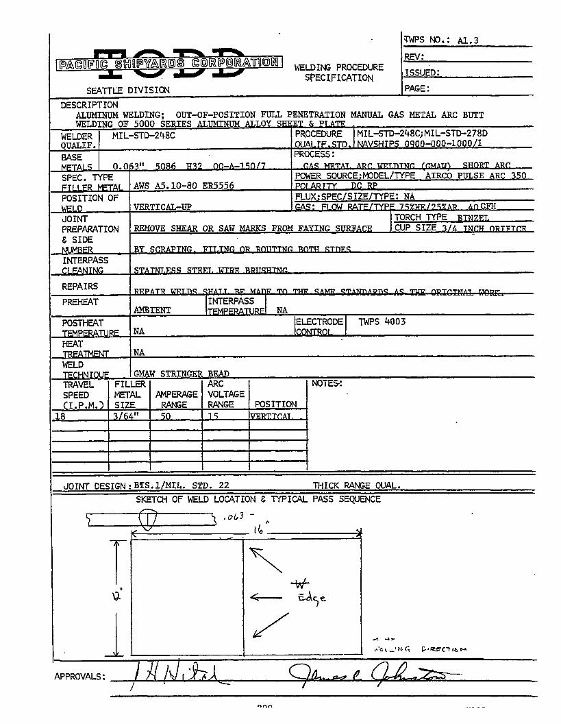

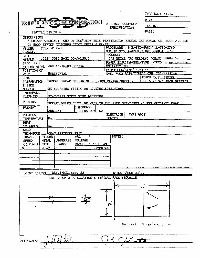
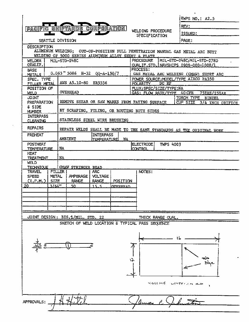

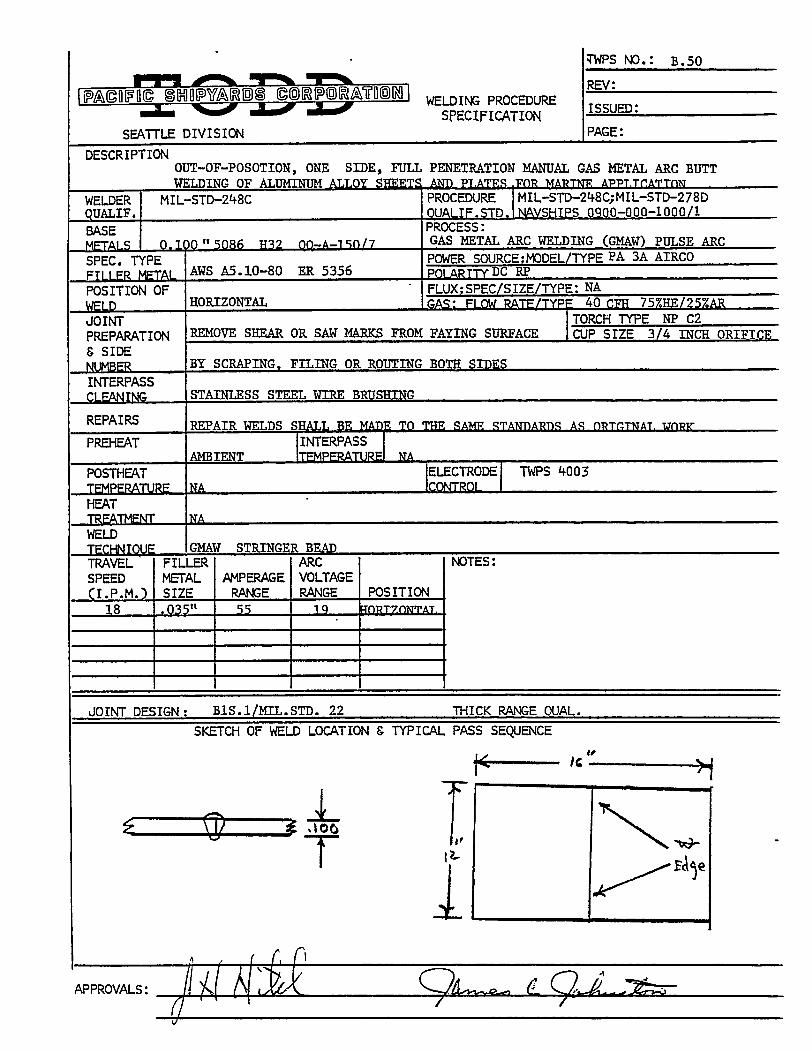

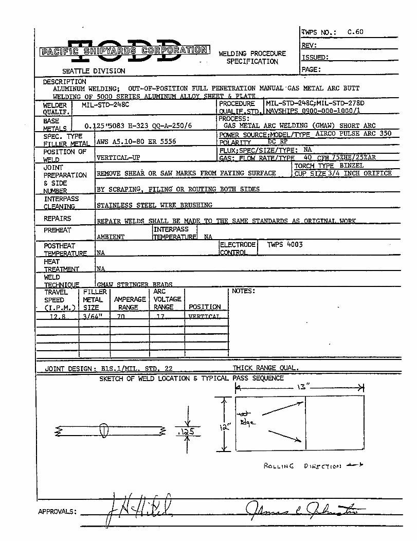


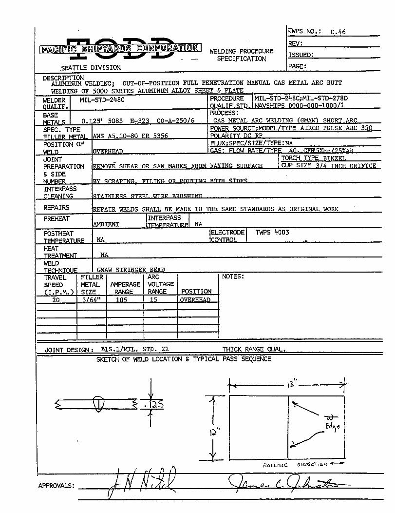
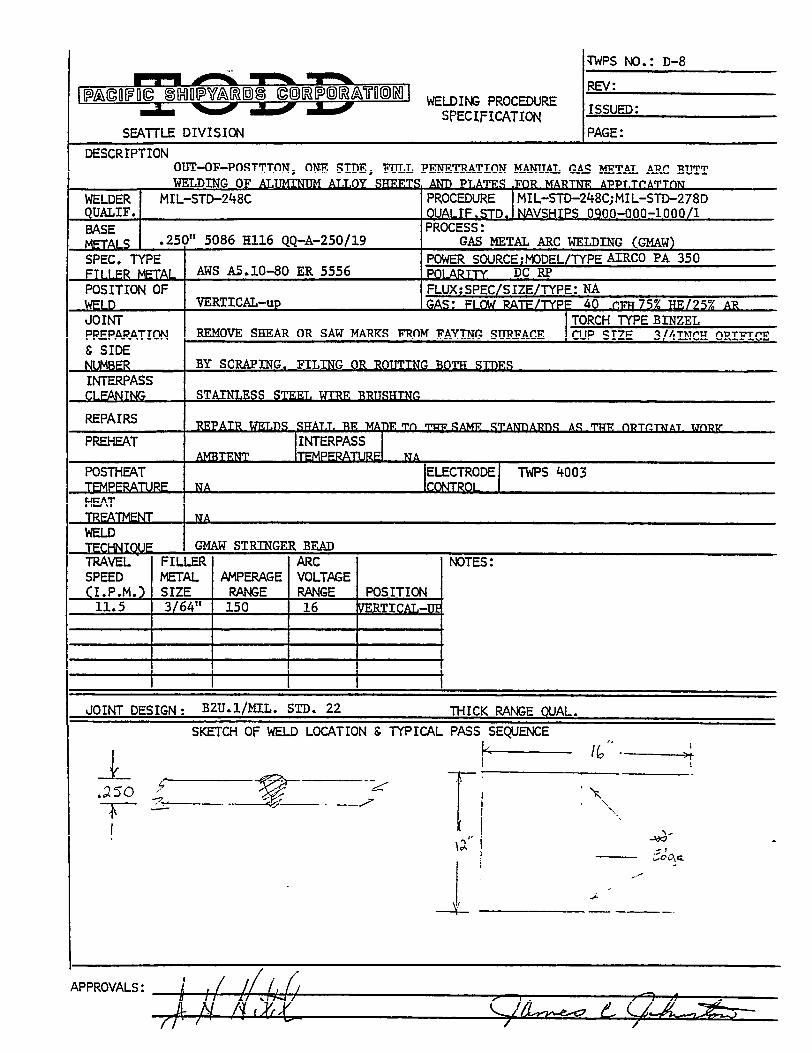
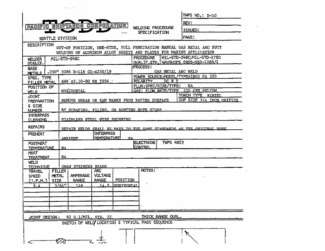
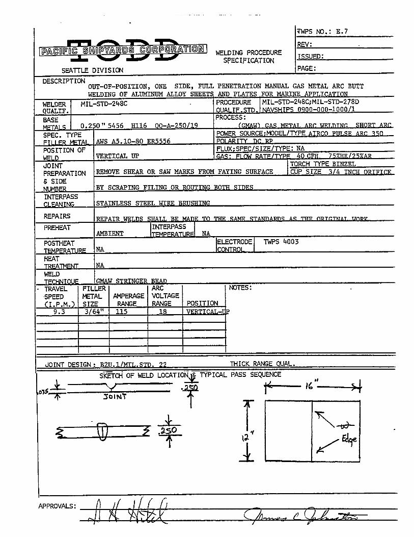
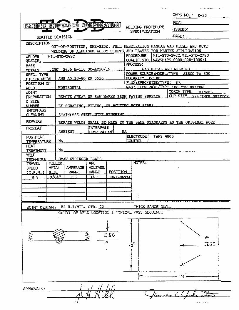
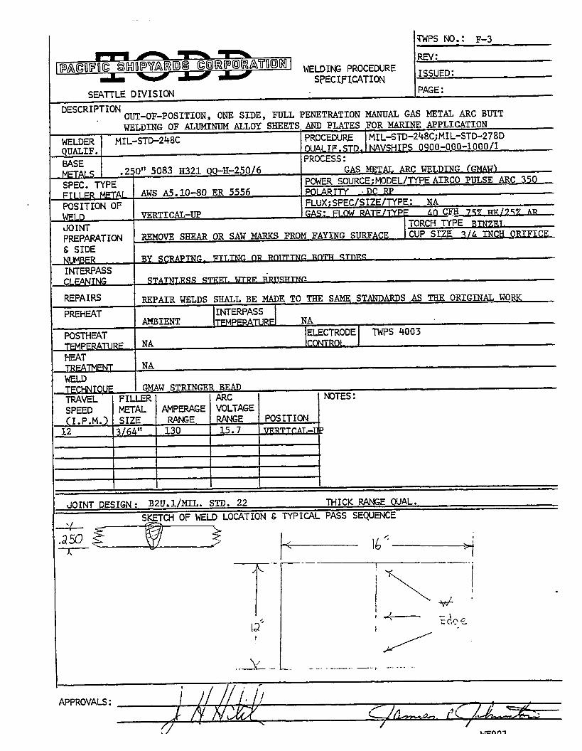
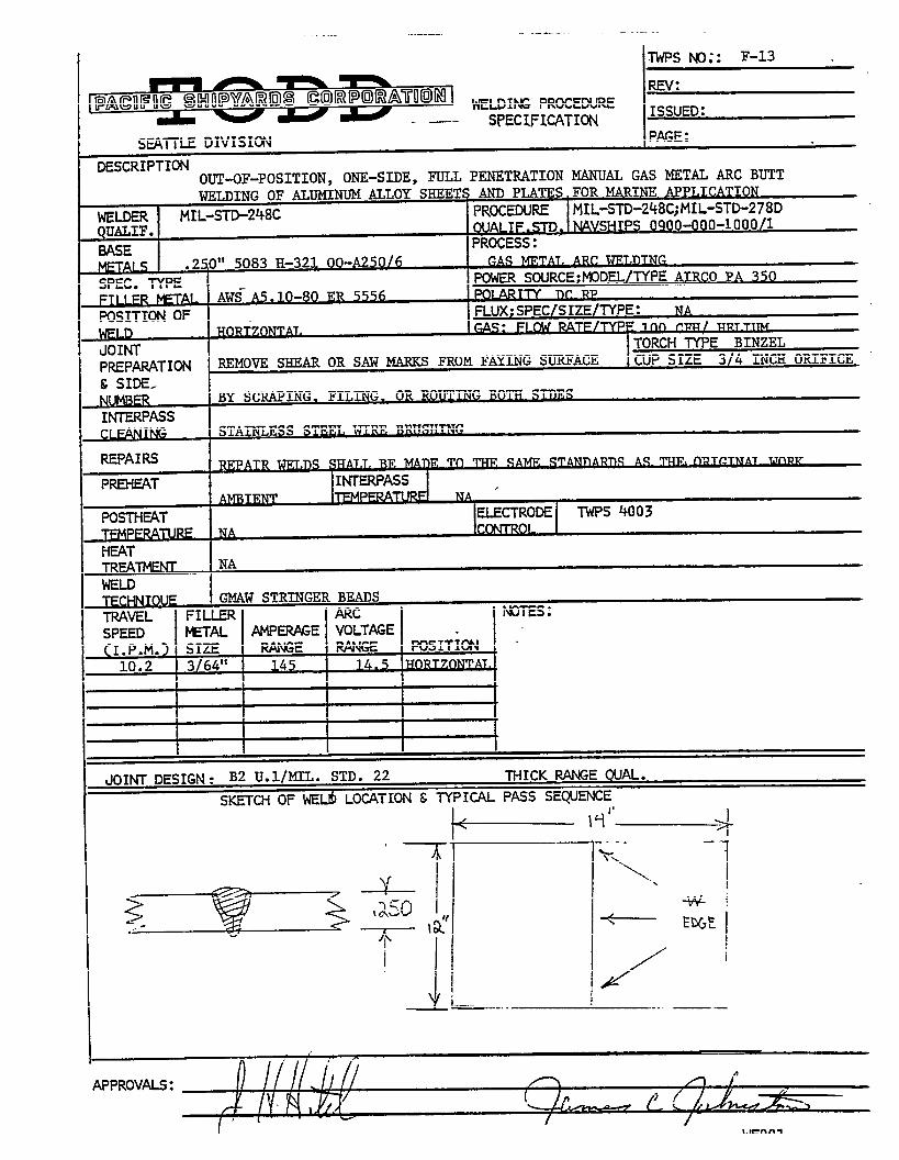
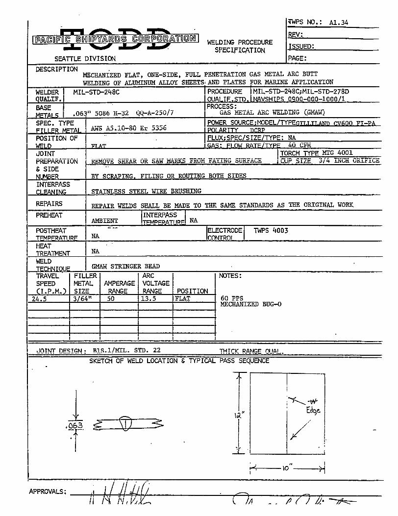
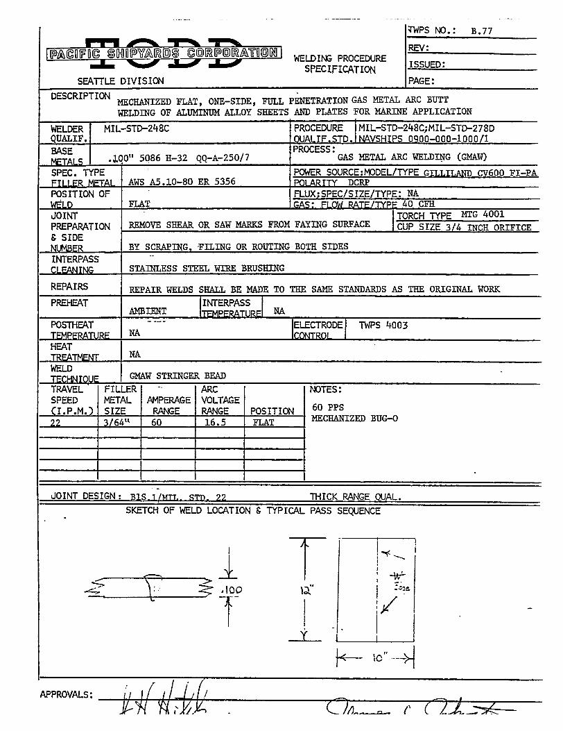
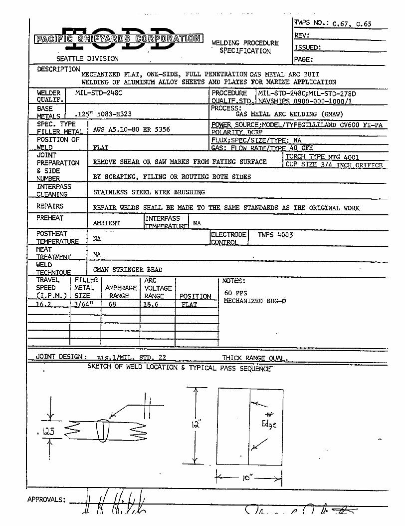
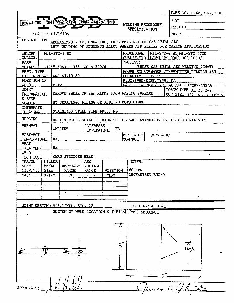
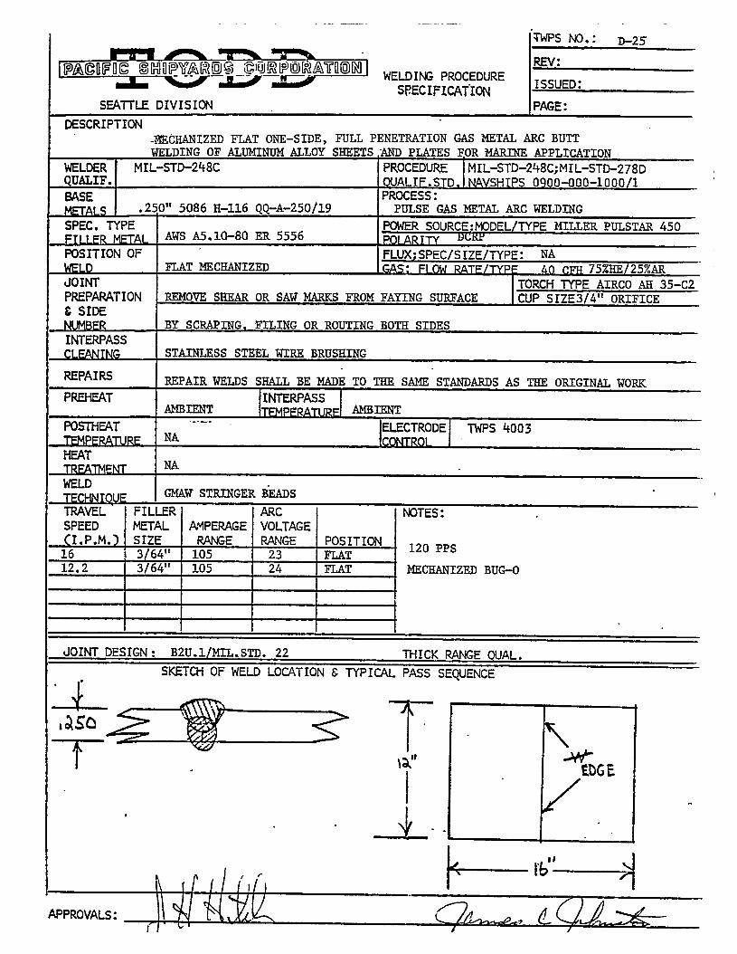
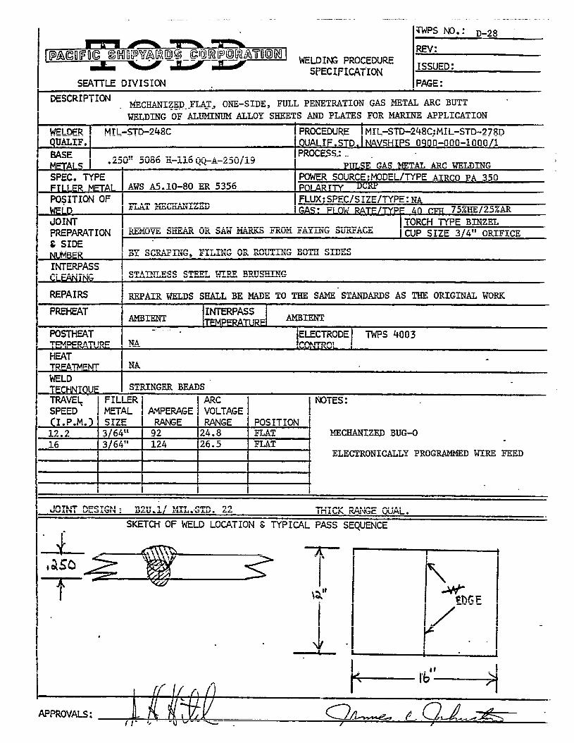
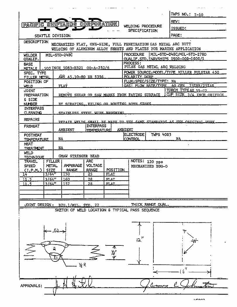
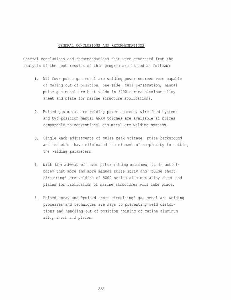
GENERAL CONCLUSIONS AND RECOMMENDATIONS
General conclusions and recommendations that were generated from the
analysis of the test results of this program are listed as follows:
1. All four pulse gas metal arc welding power sources were capable
of making out-of-position, one-side, full penetration, manual
pulse gas metal arc butt welds in 5000 series aluminum alloy
sheet and plate for marine structure applications.
2. Pulsed gas metal arc welding power sources, wire feed systems
and two position manual GMAW torches are available at prices
comparable to conventional gas metal arc welding systems.
3. Single knob adjustments of pulse peak voltage, pulse background
and induction have eliminated the element of complexity in setting
the welding parameters.
4. With the advent of newer pulse welding machines, it is antici-
pated that more and more manual pulse spray and “pulse short-
circuiting” arc welding of 5000 series aluminum alloy sheet and
plates for fabrication of marine structures will take place.
5. Pulsed spray and “pulsed short-circuiting” gas metal arc welding
processes and techniques are keys to preventing weld distor-
tions and handling out-of-position joining of marine aluminum
alloy sheet and plates.
323