Today I will cover the following topics
48
1
Transcript of Today I will cover the following topics

1
Today I will cover the following topics
The changes that have occurred to mainframe storage technology since DB2
was introduced
I cover the various IBM copy technologies as well as EMC’s and Hitachi’s.\
Finally I will cover how IBM’s and BMC’s utilities exploit these technologies
2
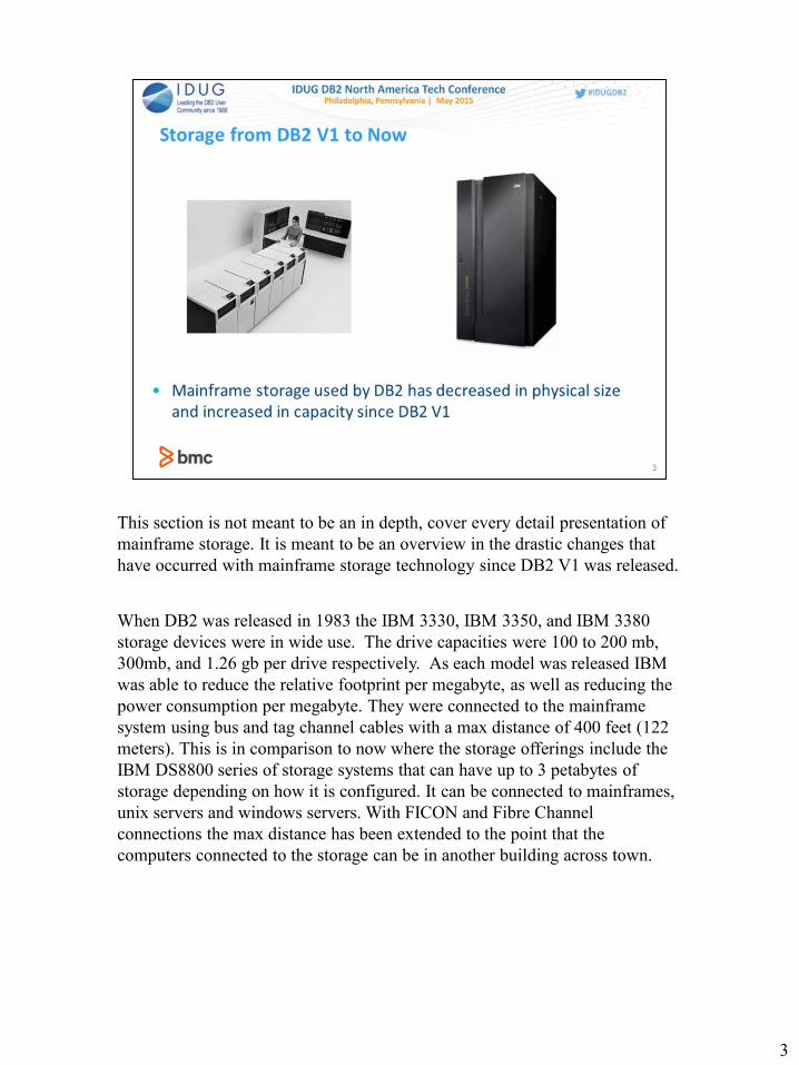
This section is not meant to be an in depth, cover every detail presentation of
mainframe storage. It is meant to be an overview in the drastic changes that
have occurred with mainframe storage technology since DB2 V1 was released.
When DB2 was released in 1983 the IBM 3330, IBM 3350, and IBM 3380
storage devices were in wide use. The drive capacities were 100 to 200 mb,
300mb, and 1.26 gb per drive respectively. As each model was released IBM
was able to reduce the relative footprint per megabyte, as well as reducing the
power consumption per megabyte. They were connected to the mainframe
system using bus and tag channel cables with a max distance of 400 feet (122
meters). This is in comparison to now where the storage offerings include the
IBM DS8800 series of storage systems that can have up to 3 petabytes of
storage depending on how it is configured. It can be connected to mainframes,
unix servers and windows servers. With FICON and Fibre Channel
connections the max distance has been extended to the point that the
computers connected to the storage can be in another building across town.
3

This picture is meant to bring home just how much storage technology has
changed.
The IBM Mass Storage cartridge holds 50mb or half of a 3330-1 and required
large complex hardware to be able to use it
The Samsung 128gb micro SD card came from one of my music players that
fits in my hand . The card has about a 1000 flac music files and is still well
over half empty
4

Storage used by DB2 in the 1980s had these common characteristics
• Each mainframe disk device was a single physical drive
• Since these physical drives tended to be rather large, the cabinets that
housed them required a bit of floor space
• This space requirement meant that data centers with large storage
requirements were also very large. It was not uncommon for disk storage to
be housed on multiple floors above and below the computer room. This
allowed large amounts of storage (for that time) to be connected to the
mainframe and still be within the 400 foot (122 meters) limit of the bus and
tag cables.
• Hard disk failures known as “head crashes” always meant an outage. At the
minimum an application was down. The worst case being the mainframe
that needed that drive was down. The outage was usually extended because
the field engineer had to determine exactly what was wrong. If they were
fortunate enough to have the correct parts on hand they could begin the
necessary repairs. If they didn’t then they had to have the parts shipped or
delivered from another location. Once the repairs were performed the
recovery process began.
5

Later cache storage was added to the storage controller for the 3380 storage
line. With the updated hardware and microcode updates to support the new
hardware, read response times were improved for data that was regularly
accessed.
1989 saw the introduction of the IBM 3990/3390. Drive capacity was
increased to 1.89gb for the 3390-1 and increased again for the 3390-2, 3390-3,
and 3390-9. The amount of cache was increased to allow more data to be
staged in cache. At this time Non-volatile cache was introduced which allowed
cached data to be updated without having to write back to the disk
immediately. The NVS cache used a battery backup to retain the data in the
case of a power failure.
ESCON channels were introduced which used fiber optic technology to
communicate between the mainframe and the controllers. This had two major
improvements. The first being that bus and tag cables were no longer needed
for devices that supported ESCON. The second was the 400 foot limitation
was no longer an issue. With addition of chained ESCON directors disk
storage and the mainframe could be as far as 60 kilometers apart (approx. 37
miles)
6
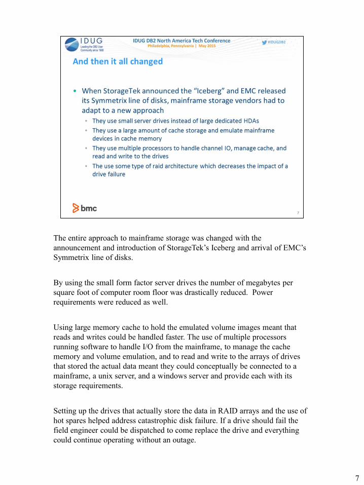
The entire approach to mainframe storage was changed with the
announcement and introduction of StorageTek’s Iceberg and arrival of EMC’s
Symmetrix line of disks.
By using the small form factor server drives the number of megabytes per
square foot of computer room floor was drastically reduced. Power
requirements were reduced as well.
Using large memory cache to hold the emulated volume images meant that
reads and writes could be handled faster. The use of multiple processors
running software to handle I/O from the mainframe, to manage the cache
memory and volume emulation, and to read and write to the arrays of drives
that stored the actual data meant they could conceptually be connected to a
mainframe, a unix server, and a windows server and provide each with its
storage requirements.
Setting up the drives that actually store the data in RAID arrays and the use of
hot spares helped address catastrophic disk failure. If a drive should fail the
field engineer could be dispatched to come replace the drive and everything
could continue operating without an outage.
7
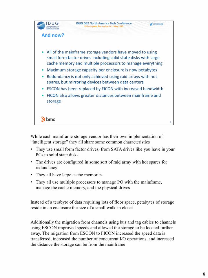
While each mainframe storage vendor has their own implementation of
“intelligent storage” they all share some common characteristics
• They use small form factor drives, from SATA drives like you have in your
PCs to solid state disks
• The drives are configured in some sort of raid array with hot spares for
redundancy
• They all have large cache memories
• They all use multiple processors to manage I/O with the mainframe,
manage the cache memory, and the physical drives
Instead of a terabyte of data requiring lots of floor space, petabytes of storage
reside in an enclosure the size of a small walk-in closet
Additionally the migration from channels using bus and tag cables to channels
using ESCON improved speeds and allowed the storage to be located further
away. The migration from ESCON to FICON increased the speed data is
transferred, increased the number of concurrent I/O operations, and increased
the distance the storage can be from the mainframe
8

As the processing power, memory and internal communication grew, more copy
functions were moved to the storage controller. Now you can keep volumes in sync
within the data center, between data centers, as well as keeping the disaster recovery
site up to date. These functions are being done at the intelligent storage level rather
than using mainframe cycles. You can also make an on demand backup of data sets or
groups of data sets that you can use to recover quickly should a problem be discovered
during a scheduled batch update.
While IBM supplies a mechanism to perform these functions via Advanced Copy
Services and all the storage vendors support these functions in some form or fashion
all the storage vendors feel compelled to use different terminology for what is
effectively if not exactly the same thing. The rest of this presentation is an attempt to
cover what features each storage provider offers. What marketing names they use to
call these features and how they relate to the Advanced Copy Services functions.
In addition, the use of small form factor drives has allowed the support for SSD, SAS,
and SATA drives. This has enabled vendors to exploit automated tier software to
migrate the data to the appropriate performance drive based on customer defined
criteria. This is done within the controller in the background without any overt action
on the part of the application accessing the data.
The last section will cover how DB2 utilities exploit these features.
9

This next topic will cover the various disaster recovery and data migration
offerings from IBM.
These are covered in depth in the DFSMS Advanced Copy Services manual
(SC23-6847-00).
11

Peer to Peer Remote Copy is one feature described in the IBM’s DFSMS
Advanced Copy Services manual. It allows one volume to be kept in sync
with another volume within a data center or between data centers. The source
volume or primary is kept in sync with the target volume or secondary as long
as the PPRC relationship is kept active. This is known as a duplexed pair. The
actual copy operations are handled at the storage hardware level.
Metro Mirror was coined when the technology allowed larger distances
between storage boxes without impacting performance. This was important as
Metro Mirror uses synchronous PPRC. This means a write I/O is not complete
until the secondary volume has acknowledged the write I/O. This is good
because the data is safely mirrored. The downside of synchronous PPRC is that
as the distance increases between the storage devices, applications waiting on
that write I/O to complete are impacted. Latency increases because the data
cannot travel faster than the speed of light at best.
Max recommended distance for ESCON is 100 kilometers (62 miles) and 200
kilometers (124 miles) for FICON
12

This diagram is an example of a PPRC or Metro Mirror setup.
The ds8800 disk subsystem that is being used by Production has devices that
are in a PPRC/Metro Mirror relationship to the ds8800 subsystem that is used
by the Disaster Recovery site.
In the case of a DR event, they can run the crecover jobs at the DR site, run
any additional recovery jobs for the database subsystems and then begin
running at the DR site.
I do want to point out that there will need to be additional recovery operations
in this scenario. It would be quite surprising if the failure that caused the DR
event happened at a point where you could safely bring up your database
subsystems without having to run various recovery jobs to insure data
integrity.
13

The cquery command is used to determine the PPRC status of a device.
The cestpair command will establish the duplex pair between two devices.
The csuspend command will suspend the duplex operation between the two
devices.
The crecover command sets the status of the secondary device to simplex
where it can then be brought online to another system
These commands require the following information: the Storage Subsystem
ID (SSID), Storage Control Serial Number, Channel Connection Address
(CCA), and Logical Subsystem (LSS) of the primary and secondary devices.
14

XRC was created to address high availability disaster recovery. This is done
through the use of the system data mover, journal data sets, high speed
communications, storage hardware that has XRC architecture support, and
similar configurations at the remote site.
It does not have to be a single vendor environment, but the storage hardware
must have similar configurations, i.e. cache size, nvs size, number of devices
and similar capacity.
Like using DB2’s System Backup, XRC requires careful planning and
specialized configurations to insure it works as expected.
XRC is now called Global Mirror for Z/Series
15

Global Mirror uses PPRC – XD to keep primary volumes in sync with
secondary volumes using asynchronous communication over much greater
distances than what Metro Mirror supports.
Flashcopy is used to create point in time copies of the secondary volumes at
the remote site
Consistency groups are set up which tell the software which group of volumes
are part of some application or even some database subsystem to insure that all
writes to any member of the group is dependent on the other writes within the
group
Finally, there is also additional software to manage, monitor, and control the
activity to insure that the data that is at the remote site is operationally
consistent.
This is not intended to be an in depth look at how Global Mirror works, but
rather a high level view of a rather complex process.
16

Consistency groups are a group of PPRC duplexed volumes that comprise an
application or database subsystem. When defined as a consistency group all
I/O writes to those volumes are treated as dependent upon one another. When a
normal PPRC duplexed pair that is not in a consistency group gets an error, it
changes to a suspend state and write I/Os continue to occur to the primary
volume. This changes with a consistency group. In that situation when an error
that would prevent the write from being successful occurs, all of the devices
are put into a long wait state and all I/Os to those devices are held. This will
keep any inconsistent updates from being propagated to the remote devices.
The reality is that some of the inconsistent I/Os may have been transmitted,
but the Global Mirror software and process has a way of resolving that
situation.
17
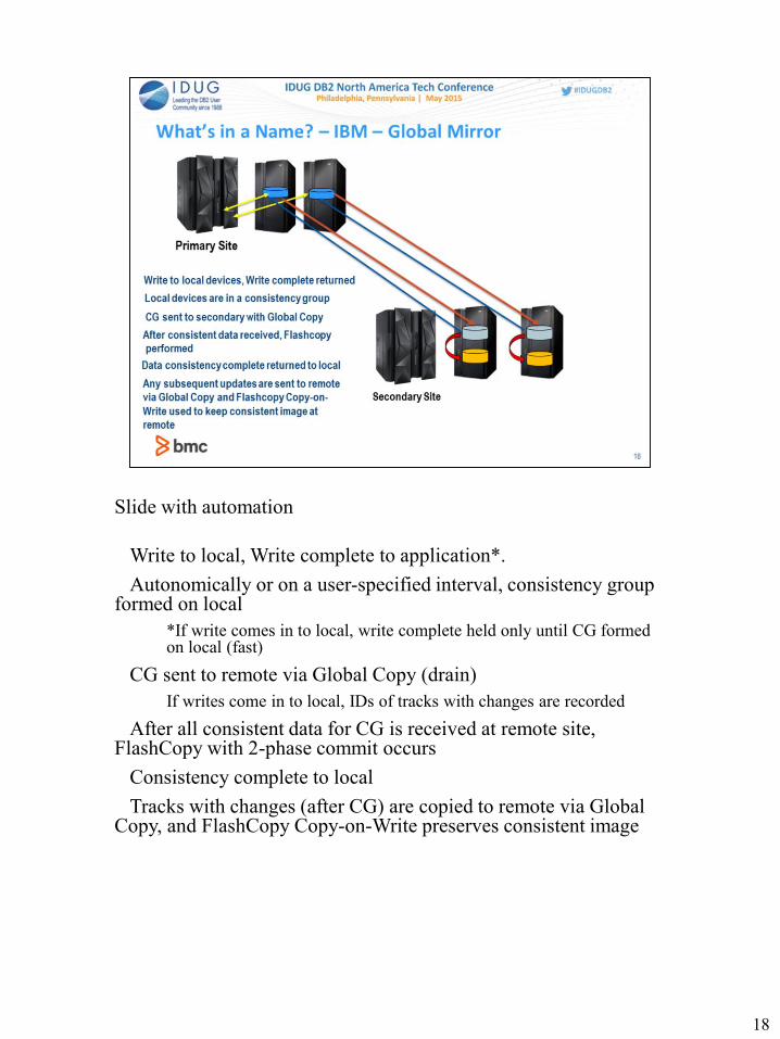
Slide with automation
1.Write to local, Write complete to application*.
2.Autonomically or on a user-specified interval, consistency group formed on local
*If write comes in to local, write complete held only until CG formed on local (fast)
3.CG sent to remote via Global Copy (drain)
If writes come in to local, IDs of tracks with changes are recorded
4.After all consistent data for CG is received at remote site, FlashCopy with 2-phase commit occurs
5.Consistency complete to local
6.Tracks with changes (after CG) are copied to remote via Global Copy, and FlashCopy Copy-on-Write preserves consistent image
18

Global mirror keeps track of the updates to the consistency groups that have
been propagated so that should an error occur it can use the consistent
flashcopy image to restore the remote volumes to the consistency point.
These flashcopy volumes are not brought online to the remote system. They
are used to maintain the latest consistency point
20

This next section covers Flashcopy which is a copy process that provides a
point in time copy of extents from a source volume to a target volume.
The range of extents can be the first track of the volume to the last track of the
volume. It can also be a subset or even a group of extents.
This operation can occur between any pair of volumes within the same
enclosure.
I want to emphasize that Flashcopy works on extents, i.e. a range of tracks. It
is utilities like DFSMSdss and Innovation’s FDR that turn a Flashcopy data set
request into a range of extents.
Once a Flashcopy establish request is started a background copy is started by
default and the Flashcopy relationship will be ended once all tracks have been
copied from the source to the target
If NOCOPY is specified, no background copy is initiated, but tracks will be
copied as they are updated on the source. A write to the source will be held up
long enough to copy the track. The Flashcopy relationship will remain active
until all tracks are copied or a Flashcopy withdraw command is issued.
21
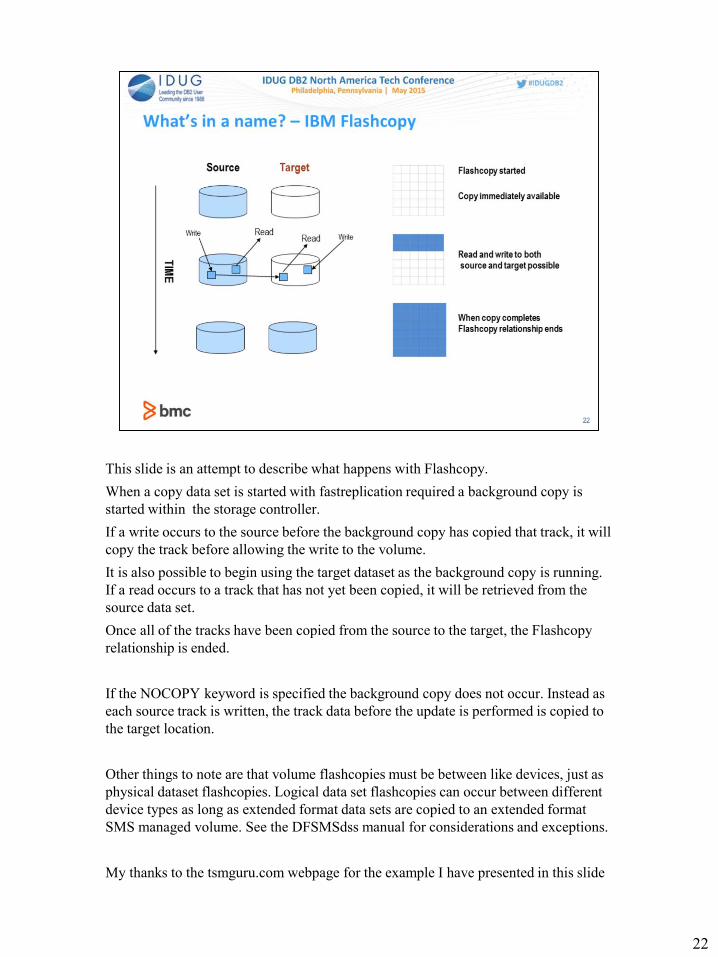
This slide is an attempt to describe what happens with Flashcopy.
When a copy data set is started with fastreplication required a background copy is
started within the storage controller.
If a write occurs to the source before the background copy has copied that track, it will
copy the track before allowing the write to the volume.
It is also possible to begin using the target dataset as the background copy is running.
If a read occurs to a track that has not yet been copied, it will be retrieved from the
source data set.
Once all of the tracks have been copied from the source to the target, the Flashcopy
relationship is ended.
If the NOCOPY keyword is specified the background copy does not occur. Instead as
each source track is written, the track data before the update is performed is copied to
the target location.
Other things to note are that volume flashcopies must be between like devices, just as
physical dataset flashcopies. Logical data set flashcopies can occur between different
device types as long as extended format data sets are copied to an extended format
SMS managed volume. See the DFSMSdss manual for considerations and exceptions.
My thanks to the tsmguru.com webpage for the example I have presented in this slide
22

There are other types of flashcopy besides volume flashcopy and data set
flashcopy.
Space Efficient Flashcopy involves special volumes called space efficient
volumes. The difference between space efficient volumes and regular volume
is that space efficient volumes share the same physical repository or pool of
storage. Since only the only data moved is the pre-update data the actual
physical storage needed should be much less. This would be useful if you want
to do volume backups to tape at a specific point in time. You cannot do a data
set space efficient flashcopy as it is a volume operation only.
Incremental Flashcopy reduces the amount of time the flashcopy relationship
is active. For instance when you take a volume flashcopy from vol1 to target1,
the background copy is initiated. Some batch cycle has completed and
everything is verified as good, you can take an incremental flashcopy before
the next batch cycle runs to have that point in time saved should you need to
recover back to that point.
23

What problem is remote pair flashcopy solving?
If flashcopy is used to make copies of db2 tables to be migrated to another
subsystem and the target volume or volumes is PPRC mirrored for DR
purposes, the DR site will be out of sync during the flashcopy operation
because the duplexed pair is suspended. Once the flashcopy is complete the
volumes are resynced. The problem is that this will cause all of that data that
was Flashcopied to be sent along the link to the remote volume. If this is
happening with multiple volumes it is possible to flood the link and take even
longer for the remote site to be synced up.
24

In this slide, a DB2 copy is run using Flashcopy from the primary device to
another device within the same controller.
Drive A and drive A’ are a duplex pair
Drive B and drive B’ are a duplex pair
A flashcopy occurs from drive A to drive B and the pprc relationships are
suspended
Once the flashcopy is complete A and A’ and B and B’ are set back to duplex
and both pairs are out of sync
All of the data that was copied from A to B plus any additional updates to B
must be written to B’. Any updates to drive A will also have to be written to
drive A’.
While these updates are being written the remote site is not an exact mirror of
the local site. If the local site should experience an outage the remote site
would not have the current data.
25
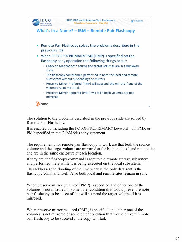
The solution to the problems described in the previous slide are solved by Remote Pair Flashcopy.
It is enabled by including the FCTOPPRCPRIMARY keyword with PMR or PMP specified in the DFSMSdss copy statement.
The requirements for remote pair flashcopy to work are that both the source volume and the target volume are mirrored at the both the local and remote site and are in the same enclosure at each location.
If they are, the flashcopy command is sent to the remote storage subsystem and performed there while it is being executed on the local subsystem.
This addresses the flooding of the link because the only data sent is the flashcopy command itself. Also both local and remote sites remain in sync.
When preserve mirror preferred (PMP) is specified and either one of the volumes is not mirrored or some other condition that would prevent remote pair flashcopy to be successful it will suspend the target volume if it is mirrored.
When preserve mirror required (PMR) is specified and either one of the volumes is not mirrored or some other condition that would prevent remote pair flashcopy to be successful the copy will fail.
26

In this slide, a DB2 copy is run using Remote Pair Flashcopy from the primary
device to another device within the same controller.
Drive A and drive A’ are a duplex pair
Drive B and drive B’ are a duplex pair
A Flashcopy occurs from drive A to drive B and FCTOPPRCPRIMARY(PMP)
was specified.
The Flashcopy request is sent to the remote controller and is performed on the
PPRC secondary volumes.
When both Flashcopies complete both sites are in sync. The only traffic across
the link was the Flashcopy request and any regular updates that have occurred
to the primary volumes.
27

29

30
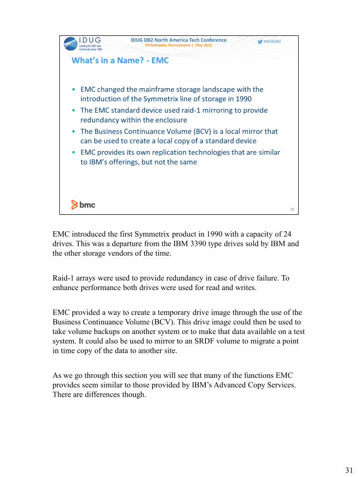
EMC introduced the first Symmetrix product in 1990 with a capacity of 24
drives. This was a departure from the IBM 3390 type drives sold by IBM and
the other storage vendors of the time.
Raid-1 arrays were used to provide redundancy in case of drive failure. To
enhance performance both drives were used for read and writes.
EMC provided a way to create a temporary drive image through the use of the
Business Continuance Volume (BCV). This drive image could then be used to
take volume backups on another system or to make that data available on a test
system. It could also be used to mirror to an SRDF volume to migrate a point
in time copy of the data to another site.
As we go through this section you will see that many of the functions EMC
provides seem similar to those provided by IBM’s Advanced Copy Services.
There are differences though.
31

In 1994 EMC introduced Symmetrix Remote Data Facility which allowed
customers to replicate their data from one enclosure to another. With SRDF/S
the data was written synchronously, meaning the host write was not complete
until the cached image of the remote device was updated. Like PPRC,
performance was impacted as the distance increased.
With asynchronous SRDF the data is sent to the remote in intervals. Although
this means that the remote device is not an exact mirror of the local device,
this technique allows them to be at greater distances from one another and to
require less bandwidth than SRDF/S
32

SRDF/Star extends SRDF so that SRDF replication can be one data center to
many data centers or many data centers to one data center.
Consistency Group functionality is provided to a set of SRDF devices with
SRDF/CG
33

The various software products under the Timefinder name all perform local
replication services.
TF/Mirror uses the pool of BCVs to create temporary copies of volumes
TF/Clone is EMCSNAP. It can perform snapshot copies of datasets or
volumes. In a RAID-5 or Raid-6 environment the TF/Mirror operation is
converted to a TF/Clone call when using clone emulation mode.
TF/CG product is the Consistency Group component.
34

To create a mirrored pair you need to issue an establish command with the BCV device number and the Source device number
When you wish to use the BCV image for local backups or to bring it online to another system, you issue the split command specifying the BCV or BCVs to be split. Unlike PPRC the BCV can be brought online without issuing an additional command to the control unit
The query command provides information about the state of the device including if it is mirrored and to what it is mirrored
The Re-Establish command will mirror the BCV to the source and copy any updated tracks to the BCV
The Restore command copies the data from the BCV back to the source volume. One example where this would be useful is if you are testing a database migration. After you have mirrored all of the volumes used by the DB2 while it is down, you can split them. Run through the migration process. To roll it back, bring down the DB2 subsystem and issue a restore for all the volumes and you can start all over again.
The Incremental Restore is different than the Restore because it only restores the changed tracks. The controller keeps track of any source tracks that have been updated. If an Incremental Restore command is issued, the only data copied back are the BCV tracks that correspond to the updated source tracks.
35

EMC’s EMCSNAP product was rebranded as TF/Clone
It provides the ability to create point in time copies of data sets or volumes and
does not require BCVs. As mentioned before when TF/Mirror operations that
are performed in a raid-5 or raid-6 environment with clone emulation or at
Enginuity 5874 level or higher, TF/Clone is used instead.
TF/Clone is also used to create space efficient snapshots using virtual devices
or VDEVS. Virtual Device snapshots track the pre-updated data through the
use of pointers and tables. It uses the SNAPPOOL to store the physical data.
The VDEVs are actual devices that can be brought online and used by the OS.
SNAPPOOL devices are not available to the OS.
The TF/Clone operations can be found in the Mainframe Enablers Timefinder
Clone Mainframe Snap Facility Product Guide
As with SRDF and TF/Mirror, TF/Clone also supports Consistency groups
36

Over time due to customer demand, EMC has put in support for the Advanced
Copy Service APIs. This allows customer to use a common command set to
manage all of their DASD rather than one set for EMC, one for IBM, and one
for Hitachi.
EMC enables different features in the storage controller’s configuration. The
Compatible Peer feature and Extended Compatible feature provide PPRC and
XRC support. The underlying actions are still using SRDF and other existing
EMC functions. Flashcopy is supported natively as of Enginuity level 5773
Remote Pair Flashcopy is supported on the latest Vmax subsystems. The
VMax 20K and 40K running Enginuity 5876.251.161.
If you wish to use EMC in a native global mirror setup it is not supported.
Also, you do not need to run EMC’s SCF started task to perform native
Flashcopy.
37

39

40

Hitachi Truecopy is Hitachi’s metro mirror or synchronous PPRC between two
physical storage subsystems
Hitachi Shadowimage is a version of PPRC used within the same storage
subsystem
A volume can have one Truecopy secondary and up to two Shadowimage
secondarys. It can also have up to three Shadowimage secondarys if there is no
Truecopy mirror
Hitachi Universal Replicator is a remote replication technology that uses
asynchronous communication and journaling to assist in consistency. There is
no distance limit. It is a pull technology, i.e. the target controller at the remote
site is managing the replication process
41

Hitachi supports some of the IBM Flashcopy offerings, such as Flashcopy
V02, SE, and Flashcopy Remote Copy
Like the other storage vendors Hitachi also offers tiered storage solution that
moves data automatically between SSD, SAS, and SATA drives using
customer defined rules.
42

44
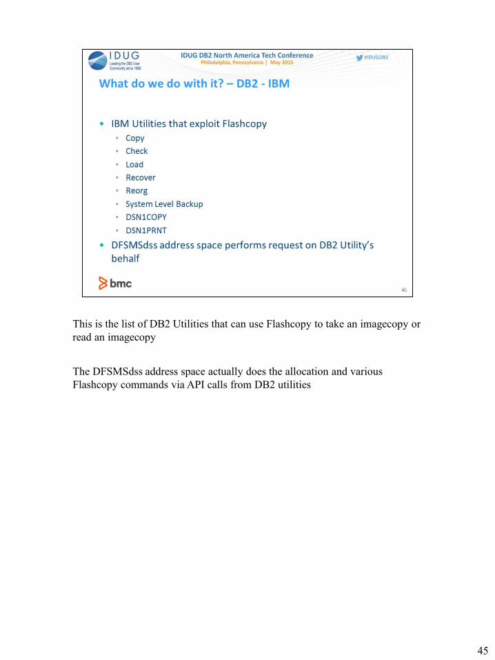
This is the list of DB2 Utilities that can use Flashcopy to take an imagecopy or
read an imagecopy
The DFSMSdss address space actually does the allocation and various
Flashcopy commands via API calls from DB2 utilities
45

These are the zparm entries used to control if Flashcopy will be used and in
some cases whether it is required or preferred.
The defaults are in bold lettering
46

System Level Backup uses Flashcopy to create a point in time copy of all the
volumes that belong to a DB2 subsystem
It requires that DB2’s catalogs are not on the same volumes as user or system
catalogs
Separate SMS pools must be created and used for DB2 Logs and the rest of the
DB2 data
System Level Backups can be used to recover individual tablespace objects
Because of the different requirements that must be met to have a successful
System Level Backup it is important to plan everything that needs to be done
and to coordinate with the DASD team to insure everything is set up and
configured correctly.
47

These are the DB2 utilities that use the FLASHCOPY YES or FLASHCOPY
CONSISTENT keyword
When Flashcopy consistent is specified uncommitted work will be backed out
during a SHARELEVEL CHANGE Operation
If the check zparm is set to use Flashcopy, Check will use Flashcopy when
doing a SHARELEVEL CHANGE Check
48
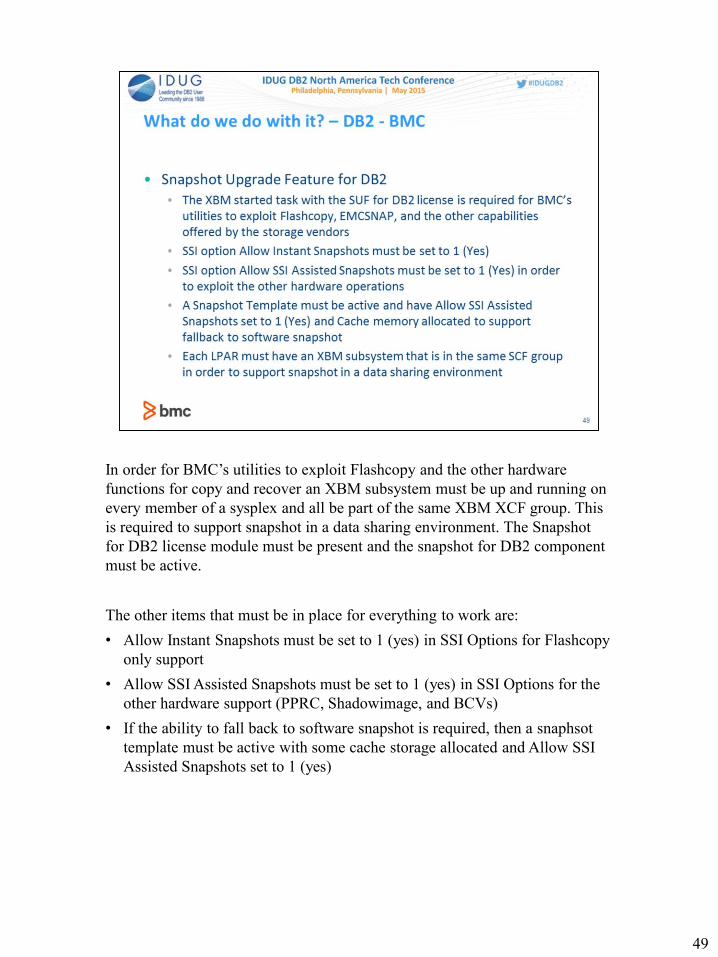
In order for BMC’s utilities to exploit Flashcopy and the other hardware
functions for copy and recover an XBM subsystem must be up and running on
every member of a sysplex and all be part of the same XBM XCF group. This
is required to support snapshot in a data sharing environment. The Snapshot
for DB2 license module must be present and the snapshot for DB2 component
must be active.
The other items that must be in place for everything to work are:
• Allow Instant Snapshots must be set to 1 (yes) in SSI Options for Flashcopy
only support
• Allow SSI Assisted Snapshots must be set to 1 (yes) in SSI Options for the
other hardware support (PPRC, Shadowimage, and BCVs)
• If the ability to fall back to software snapshot is required, then a snaphsot
template must be active with some cache storage allocated and Allow SSI
Assisted Snapshots set to 1 (yes)
49

SUF also provides the ability to perform copies from the offline mirrors of
PPRC duplexed pairs, EMC BCVs and Hitachi Shadowimage mirrors
This is provided through a setting in the XBM subsystems SSI Options and the
Snapshot Template and do not require any special keywords from the BMC
utilities
The BMC Utilities can request data set level images or “Instant Snapshot”
copies through the use of a keyword
50

The BMC utilities that overtly use hardware are Copy Plus for DB2, Recover
Plus for DB2, Reorg Plus for DB2, and through its use of Copy Plus for DB2
and Recover Plus for DB2, Recovery Manager for DB2
The Copy Plus for DB2 syntax DSSNAP with Yes or Auto will use hardware
features to perform the copy.
Recover Plus for DB2 will use XBM SUF to perform a hardware based
recovery with XBMSSID specified and the image copy entry in bmcxcopy or
if the syscopy entry indicates it is a Flashcopy image copy
Reorg Plus for DB2 use of the SIXSNAP option tells REORG PLUS whether
to use the Instant Snapshot technology of XBM and SUF to create a copy of
storage-group-defined nonpartitioned indexes in SHARELEVEL
REFERENCE or SHARELEVL CHANGE partial tablespace reorg
51
52

53