TO THE DRAWINGS AND THE PROJECT MANUAL
26
NO. 3 TO THE DRAWINGS AND THE PROJECT MANUAL PROJECT NAME: Renovations to Mustang-Panther Stadium Package B CLIENT NAME: Grapevine-Colleyville ISD LOCATION: Grapevine, Texas PROJECT NUMBER: 1710-02-01 PROPOSAL DATE: Tuesday, October, 12 th , 2017, 2:00 PM ADDENDUM DATE: Friday, October 6 th , 2017 For additional information regarding this project, contact Ty Parsons at [email protected]. THIS ADDENDUM INCLUDES: Civil Items 0 Pages Landscape Items 0 Pages Structural Items 2 Pages Architectural Items 3 Pages Plumbing Items 1 Pages Mechanical Items 1 Pages Electrical Items 0 Pages Technology Items 1 Pages AND ALL ATTACHED REVISED DRAWING REFERENCES IN THE ADDENDUM
Transcript of TO THE DRAWINGS AND THE PROJECT MANUAL

NO. 3
TO THE DRAWINGS AND THE PROJECT MANUAL
PROJECT NAME: Renovations to Mustang-Panther Stadium Package B
CLIENT NAME: Grapevine-Colleyville ISD
LOCATION: Grapevine, Texas
PROJECT NUMBER: 1710-02-01
PROPOSAL DATE: Tuesday, October, 12th , 2017, 2:00 PM
ADDENDUM DATE: Friday, October 6th, 2017
For additional information regarding this project, contact Ty Parsons at [email protected].
THIS ADDENDUM INCLUDES:
Civil Items 0 Pages
Landscape Items 0 Pages
Structural Items 2 Pages
Architectural Items 3 Pages
Plumbing Items 1 Pages
Mechanical Items 1 Pages
Electrical Items 0 Pages
Technology Items 1 Pages
AND ALL ATTACHED REVISED DRAWING REFERENCES IN THE ADDENDUM
ltaylor
Rectangle
ltaylor
Lowell's Seal with Signature and Date

Project Name: Renovations to Mustang-Panther Stadium Package B Client: Grapevine-Colleyville ISD Grapevine, Texas Project Number: 1710-02-01
Architectural Items For Addendum No. 3
Page 1 of 3
ARCHITECTURAL ITEMS FOR ADDENDUM NO. 3 NOTICE TO PROPOSERS:
A. This Addendum shall be considered part of the contract documents for the above-mentioned project as though it had been issued at the same time and incorporated integrally therewith. Where provisions of the following supplementary data differ from those of the original contract documents, this Addendum shall govern and take precedence.
B. Proposers are hereby notified that they shall make any necessary adjustments in their estimate on account of this Addendum. It will be construed that each Proposer’s proposal is submitted with full knowledge of all modifications and supplemental data specified therein. Acknowledge receipt of this addendum in the space provided on the proposal form. Failure to do so may subject Proposer to disqualification.
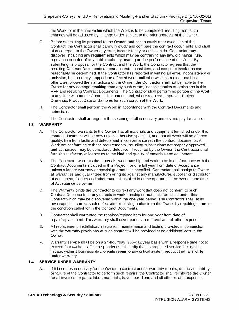
REFERENCE IS MADE TO THE DRAWINGS AND THE PROJECT MANUAL AS NOTED: DRAWINGS: AD No 3, Arch. Item 1: To the Drawings, Sheet A1.3, “FLOOR PLAN-BLDG. A PRESS BOX LEVEL 1,”
1) Updated floor plan to replace folding partition FP3.01 with door A3.11. See attached sheet for door location.
AD No 3, Arch. Item 2: To the Drawings, Sheet A3.1, “DOR, WINDOW, CURTAIN WALL SCHEDULE AND CONFIGURATIONS,”
1) Folding partition has been replaced with a pair of full glass doors. See attached sheet for configuration. RFI RESPONSES:
AD No 3, Arch. Item 3: Question: Define the location of the temporary video control in the MDF room or other location for a contingency fee. When is this work supposed to be completed? Will it be done as part of this job, or do we just need to be prepared for it to be done at a later date (under a separate contract)? Answer: Per Crux - Per section 11 6843 item 2.20.B Contractor needs to be financially prepared to cover costs associated with the set up, take down of the system from one location to the press box.
AD No 3, Arch. Item 4: Question: Is the owner setting the amount for this relocation contingency fee? Answer: Per Crux - No.
ltaylor
Rectangle
ltaylor
Lowell's Seal with Signature and Date

Project Name: Renovations to Mustang-Panther Stadium Package B Client: Grapevine-Colleyville ISD Grapevine, Texas Project Number: 1710-02-01
Architectural Items For Addendum No. 3
Page 2 of 3
AD No 3, Arch. Item 5: Question: The height dimensions for the brickwork on the existing scoreboard structure (AS1.4) are very different from the steel structure that is currently onsite. Will modifications be made to drawing AS1.4 to match existing structure? The height of the structure in the current drawing will require new full structure design and removal of existing structure. It was understood that GCISD wanted to utilize existing structure for cost savings. Answer: The structure as shown in the bid documents assumes new structure for the scoreboard due to lack of information from Vendors on possible structural implications. The drawings will be revised once structural information is provided based on either re-use of existing structure if possible, or new structure if deemed necessary. The winning bidder will need to provide this information once bids have been accepted and approved by the concerned parties for this project, and the documents will then be revised to reflect the correct structural application.
AD No 3, Arch. Item 6: Question: Who is responsible for the brickwork shown on AS1.4? Will it be required regardless of whether or not a new structure is put up? Answer: Lee Lewis Construction will provide the masonry and labor to install brick veneer.
AD No 3, Arch. Item 7: Question: GCISD had requested alternate pricing for adding service catwalks to the back of the structure. There is nothing in the Bid for alternate catwalks. Answer: Bidding vendors needs to provide this as an alternate item in their bid documents. Lee Lewis Construction and District will determine if it is accepted at that time after discussions with Huckabee personnel.
AD No 3, Arch. Item 8: Question: Would GCISD accept a substitution for TI-2003 Play Clocks with newer TI-2034 Game/Play Clocks Answer: Per Crux - The 2034’s is already specified under Item 2.11.A

Project Name: Renovations to Mustang-Panther Stadium Package B Client: Grapevine-Colleyville ISD Grapevine, Texas Project Number: 1710-02-01
Architectural Items For Addendum No. 3
Page 3 of 3
AD No 3, Arch. Item 9: Question: In the Bid, there are no call outs for Locker Room Clocks (TI-2013) in the team rooms or official’s rooms. If GCISD would like locker room clocks what would be the locations and quantity? (see attached Spec Sheet for power and signal conduit routing) Answer: Per Crux - No locker room clocks are required. This was discussed in the design meetings and was rejected by the owner.
END OF ARCHITECTURAL ADDENDUM

Project Name: Renovations to Mustang-Panther Stadium Package B
Client: Grapevine-Colleyville ISD Grapevine, Texas Project Number: 1710-02-01
Plumbing Items For Addendum No. 3
Page 1 of 1
PLUMBING ITEMS FOR ADDENDUM NO. 3 NOTICE TO PROPOSERS:
A. This Addendum shall be considered part of the contract documents for the above-mentioned project as though it had been issued at the same time and incorporated integrally therewith. Where provisions of the following supplementary data differ from those of the original contract documents, this Addendum shall govern and take precedence.
B. Proposers are hereby notified that they shall make any necessary adjustments in their estimate on account of this Addendum. It will be construed that each Proposer’s proposal is submitted with full knowledge of all modifications and supplemental data specified therein. Acknowledge receipt of this addendum in the space provided on the proposal form. Failure to do so may subject Proposer to disqualification.
REFERENCE IS MADE TO THE DRAWINGS AND THE PROJECT MANUAL AS NOTED: PROJECT MANUAL: DRAWINGS:
AD No 3, Plumb. Item 1: To the Drawings, Sheet P3.1B, “Roof Plans – Bldg. A & West Entry - Plumbing,”
Drawing is reissued, adjusting gas piping layout to new HVAC unit locations.
END OF PLUMBING ADDENDUM

Project Name: Renovations to Mustang-Panther Stadium Package B
Client: Grapevine-Colleyville ISD Grapevine, Texas Project Number: 1710-02-01
Mechanical Items For Addendum No. 3
Page 1 of 1
MECHANICAL ITEMS FOR ADDENDUM NO. 3 NOTICE TO PROPOSERS:
A. This Addendum shall be considered part of the contract documents for the above-mentioned project as though it had been issued at the same time and incorporated integrally therewith. Where provisions of the following supplementary data differ from those of the original contract documents, this Addendum shall govern and take precedence.
B. Proposers are hereby notified that they shall make any necessary adjustments in their estimate on account of this Addendum. It will be construed that each Proposer’s proposal is submitted with full knowledge of all modifications and supplemental data specified therein. Acknowledge receipt of this addendum in the space provided on the proposal form. Failure to do so may subject Proposer to disqualification.
REFERENCE IS MADE TO THE DRAWINGS AND THE PROJECT MANUAL AS NOTED: PROJECT MANUAL: DRAWINGS:
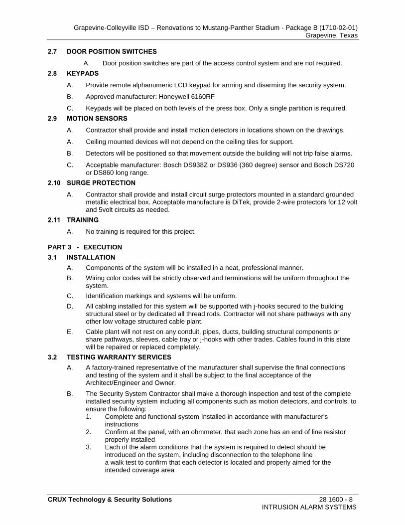
AD No3, Mech. Item 1: To the Drawings, Sheet M2.3B, “Floor Plan – Bldg. A Press Box Level 1 – H.V.A.C.,”
Drawing is reissued, modifying ductwork layout.
AD No3, Mech. Item 2: To the Drawings, Sheet M2.4B, “Floor Plan – Bldg. A – Press Box Level 2 – H.V.A.C.,”
Drawing is reissued, modifying ductwork layout and relocating RTAC #PB-1.
AD No3, Mech. Item 3: To the Drawings, Sheet M3.1B, “Roof Plan – Bldg. A – H.V.A.C.,”
Drawing is reissued, relocating RTAC #PB-1 and modifying condensate drain piping.
END OF MECHANICAL ADDENDUM

Project Name: Renovations to Mustang-Panther Stadium Package B Client: Grapevine-Colleyville ISD Grapevine, Texas Project Number: 1710-02-01
Technology Items for Addendum No. 1
Page 1 of 1
TECHNOLOGY ITEMS FOR ADDENDUM NO. 3 NOTICE TO PROPOSERS:
A. This Addendum shall be considered part of the contract documents for the above-mentioned project as though it had been issued at the same time and incorporated integrally therewith. Where provisions of the following supplementary data differ from those of the original contract documents, this Addendum shall govern and take precedence.
B. Proposers are hereby notified that they shall make any necessary adjustments in their estimate on account of this Addendum. It will be construed that each Proposer’s proposal is submitted with full knowledge of all modifications and supplemental data specified therein. Acknowledge receipt of this addendum in the space provided on the proposal form. Failure to do so may subject Proposer to disqualification.
REFERENCE IS MADE TO THE DRAWINGS AND THE PROJECT MANUAL AS NOTED: PROJECT MANUAL:
AD No 3, Tech. Item 1: To the project Manual, Section 11 6843. “Scoreboards” Add item 2.2.P as follows: Contractor shall include the installation of the board manufacturer’s maintenance catwalk system on the back of the scoreboard as a standalone line item price for the owner to select from.
AD No 3, Tech. Item 2: To the project Manual, Section 11 6843. “Scoreboards” Add item 2.14.C as follows: Contractor shall include the installation of the board manufacturer’s maintenance catwalk system on the back of the scoreboard as a standalone line item price for the owner to select from.
AD No 3, Tech. Item 3: To the Project Manual, Section 28 1600, “Intrusion Alarm Systems,” Added this specification in its entirety. DRAWINGS: AD No 3, Tech. Item 4: To the Drawings, Sheet TS1.1, “Technology Site Plan”
1) Deleted an unrequired conduit pathway.
AD No 3, Tech. Item 5: To the Drawings, Sheet T1.5, “Floor Plan – Building A, Press Box Level 1 and Upper Concourse RCP”
1) Added motion detectors in the RCP. 2) Added keypad location near elevator.
AD No 3, Tech. Item 6: To the Drawings, Sheet T1.6, “Floor Plan – Bldg A Press Box Level 2” 1) Added motion detectors in the RCP. 2) Added intrusion alarm panel in IDF room. 3) Added data outlet above ceiling for intrusion panel connection. 4) Added keypad location near elevator.
AD No 3, Tech. Item 7: To the Drawings, Sheet T4.2, “IDF/MDF Plans and Elevations” 1) Added intrusion alarm panel in elevation details and note 19.
END OF TECHNOLOGY ADDENDUM

Grapevine-Colleyville ISD – Renovations to Mustang-Panther Stadium - Package B (1710-02-01) Grapevine, Texas
CRUX Technology & Security Solutions 28 1600 - 1 INTRUSION ALARM SYSTEMS
SECTION 28 1600
INTRUSION ALARM SYSTEMS
PART 1 - GENERAL
1.1 SCOPE
A. Related Documents: General and Supplementary Conditions of the Contract, Division 1 General Requirements, and Drawings are applicable to this Section.
B. Furnish and install, complete with all accessories a complete and functioning intrusion alarm system.
C. The Contractor shall provide all materials, equipment, labor and all other incidental materials and appliances necessary, as described herein and in the drawings, to provide a complete turn-key and functional system, regardless of any materials and/or equipment not listed or described in this specification and/or supplementary drawings.
D. Refer to the technology drawings for all keypad and panel locations.
E. All components, to include cabling mounted above ceilings shall be approved for use in plenum spaces.
F. It shall be the responsibility of the Contractor to obtain all required approvals and certifications from authorities having jurisdiction.
G. The Contractor shall coordinate the system installation and programming with the owner.
1.2 SUMMARY
A. The following is a summary of the Contractor’s Responsibilities and Requirements. The following does not preclude other Contractor Responsibilities and Requirements listed in this RFP.
B. Review of Contract Documents and field conditions by Contractor prior to the Work.
C. The Owner makes no representations as to the accuracy or completeness of the site information furnished to the Contractor by the Owner and does not expressly or impliedly warrant same and is not responsible for any interpretations or conclusions reached by the Contractor with respect thereto. It is Contractor's sole responsibility to verify to its own satisfaction all the site information.
D. The Contractor is responsible for having visited the site and ascertained pertinent local conditions such as location, accessibility, and character of the site or building, the character and extent of existing work within and adjacent to the site, and any other work being performed thereon at the time of the submission of his proposal. Any failure to do so will not relieve him from responsibility for successfully performing the work without additional expense to the Owner.
E. The Contractor shall take field measurements and verify field conditions and shall carefully compare such field measurements and conditions and other information known to the Contractor with the Contract Documents before commencing activities. Errors, inconsistencies or omissions discovered shall be reported to the Owner at once.
F. If in the performance of the Contract, subsurface, latent, or concealed conditions at the site are found to be materially different from the information included in the RFP and the resulting Contract Documents, or if unknown conditions of an unusual nature are disclosed differing materially from the conditions usually inherent in work of the character shown and specified, the Owner shall be notified in writing of such conditions before they are disturbed. A/E, with the approval of the Owner, will promptly make such changes to the Specifications as deemed necessary to conform to the different conditions, and any increase or decrease in
Grapevine-Colleyville ISD – Renovations to Mustang-Panther Stadium - Package B (1710-02-01) Grapevine, Texas
CRUX Technology & Security Solutions 28 1600 - 2 INTRUSION ALARM SYSTEMS
the Work, or in the time within which the Work is to be completed, resulting from such changes will be adjusted by Change Order subject to the prior approval of the Owner.
G. Before submitting its proposal to the Owner, and continuously after execution of the Contract, the Contractor shall carefully study and compare the contract documents and shall at once report to the Owner any error, inconsistency or omission the Contractor may discover, including any requirements which may be contrary to any law, ordinance, rule, regulation or order of any public authority bearing on the performance of the Work. By submitting its proposal for the Contract and the Work, the Contractor agrees that the resulting Contract Documents appear accurate, consistent, and complete insofar as can reasonably be determined. If the Contractor has reported in writing an error, inconsistency or omission, has promptly stopped the affected work until otherwise instructed, and has otherwise followed the instructions of the Owner, the Contractor shall not be liable to the Owner for any damage resulting from any such errors, inconsistencies or omissions in this RFP and resulting Contract Documents. The Contractor shall perform no portion of the Work at any time without the Contract Documents and, where required, approved Project Drawings, Product Data or Samples for such portion of the Work.
H. The Contractor shall perform the Work in accordance with the Contract Documents and submittals.
I. The Contractor shall arrange for the securing of all necessary permits and pay for same.
1.3 WARRANTY
A. The Contractor warrants to the Owner that all materials and equipment furnished under this contract document will be new unless otherwise specified, and that all Work will be of good quality, free from faults and defects and in conformance with the contract documents. All Work not conforming to these requirements, including substitutions not properly approved and authorized, may be considered defective. If required by the Owner, the Contractor shall furnish satisfactory evidence as to the kind and quality of materials and equipment.
B. The Contractor warrants the materials, workmanship and work to be in conformance with the Contract Documents included in this Project, for one full year from date of Acceptance unless a longer warranty or special guarantee is specified. Contractor shall assign to Owner all warranties and guarantees from or rights against any manufacturer, supplier or distributor of equipment, fixtures and other material installed in or incorporated in the Work at the time of Acceptance by owner.
C. The Warranty binds the Contractor to correct any work that does not conform to such Contract Documents or any defects in workmanship or materials furnished under this Contract which may be discovered within the one year period. The Contractor shall, at its own expense, correct such defect after receiving notice from the Owner by repairing same to the condition called for in the Contract Documents.
D. Contractor shall warrantee the repaired/replace item for one year from date of repair/replacement. This warranty shall cover parts, labor, travel and all other expenses.
E. All replacement, installation, integration, maintenance and testing provided in conjunction with the warranty provisions of such contract will be provided at no additional cost to the Owner.
F. Warranty service shall be on a 24-hour/day, 365-day/year basis with a response time not to exceed four (4) hours. The respondent shall certify that its proposed service facility shall initiate, within 1 business day, on-site repair to any critical system product that fails while under warranty.
1.4 SERVICE UNDER WARRANTY
A. If it becomes necessary for the Owner to contract out for warranty repairs, due to an inability or failure of the Contractor to perform such repairs, the Contractor shall reimburse the Owner for all invoices for parts, labor, materials, travel, per-diem, and all other related expenses

Grapevine-Colleyville ISD – Renovations to Mustang-Panther Stadium - Package B (1710-02-01) Grapevine, Texas
CRUX Technology & Security Solutions 28 1600 - 3 INTRUSION ALARM SYSTEMS
such as shipping/handling costs to perform such repairs, within 30 days from presentation of an invoice from the Owner. 1. This shall only occur after the Contractor has been given reasonable time and fair
opportunity to respond and correct the problem. The cost limitation for such repairs will not exceed the actual costs as listed above which are directly related to the repair.
1.5 MAINTENANCE AND SUPPORT
A. The Contractor will describe the extent, availability and cost of ongoing maintenance and technical support for the proposed system.
1.6 MATERIAL AND WORKMANSHIP
A. The Contractor shall provide and pay for all materials, supplies, machinery, equipment, tools, superintendence, labor, services, insurance, and all water, fuel, transportation, and other facilities necessary for the execution and completion of the work covered by the Contract Documents.
B. Unless otherwise specifically provided in this Contract, all equipment, material, and articles incorporated in the work covered by this Contract are to be new and of the most suitable grade for the purpose intended.
C. All work under this Contract shall be performed in a skillful and professional manner. The Contractor agrees to employ only orderly and competent employees, skillful in the performance of the type of work required under this contract; and agrees that whenever informed by the Owner in writing that any employee(s) on the work is (are), in its opinion, incompetent, unfaithful or disorderly, shall be discharged from the work and shall not again be employed on the work without the Owner's written consent.
D. Materials or work described in words, which so applied, have a well-known technical or trade meaning shall be held to refer to such recognized standards. Neither custom nor usage of trade shall require the Owner to accept materials or workmanship not in strict and complete compliance with the Contract Documents.
1.7 QUALIFICATIONS
A. Acceptable Manufacturer 1. The District accepted manufacturer for this system is: Honeywell Ademco Vista
B. Contractor 1. The proposed contractor, as a business entity, shall be an authorized and designated
representative of the equipment manufacturer, with full warranty privileges, and shall have been actively engaged in the business of selling, installing and servicing commercial security systems for a period of at least five (5) years.
2. The contractor will utilize the authorized manufacturer components and distribution channels in provisioning this Project. Contractors must be prepared to submit authorized manufacturer factory training certificates.
3. Contractor will comply with all federal, state and local statutes regarding qualifications of firms.
4. The contractor will have adequately trained personnel in the usage of such tools and equipment and will provide a quantity of certified technicians as part of their submittal response. No contract employees are allowed unless they have been to the factory service school within the last 18 months.
5. Companies who have recently become certified by the manufacturer may be permitted to bid if they receive pre-approval from the architect / owner based on the experience of identified personnel, a list of current and completed projects since the company’s inception and all licensing requirements by the state are already met. All information must be turned over to the architect no less than 10 days prior to the contract proposal date.

Grapevine-Colleyville ISD – Renovations to Mustang-Panther Stadium - Package B (1710-02-01) Grapevine, Texas
CRUX Technology & Security Solutions 28 1600 - 4 INTRUSION ALARM SYSTEMS
6. The contractor must have previously established offices located within 150 miles of the District Administration Building. The contractor shall be capable of dispatching technicians to repair a system within six (6) hours of a service request.
7. The contractor shall provide proof of licensing by the Texas Board on Private Security run by the Department of Public Safety.
8. The Owner reserves the right to reject bid of any bidder who has previously failed to perform properly, or complete on time, contracts of a similar nature. Contractors who fail to demonstrate or provide adequate support to their qualifications or who fail to demonstrate the resources to complete the work specified in this document may be disqualified at the Owner’s discretion.
9. Records of grievances or complaints
C. Subcontractors 1. The use of unlicensed sub-contractors for this project is not approved.
1.8 SUBMITTALS AND CLOSE OUT DOCUMENTS
A. Successful contractor will submit an electronic PDF copy of the submittal package within 15 days of written notification to proceed or other written documentation from the Architect or General Contractor. Binders will be organized into the following sections:
B. Provide product data cut sheets for all listed products in section two of this specification as per Section 01 3300 with the following provisions: 1. Shop drawings are not required for the submittal package. 2. Equipment list (Schedule of values or materials lists) will include the manufacturer
name, model number and description of each listed component. a. If the data sheet includes multiple part numbers or models the bidding
contractor will indicate which model is being submitted by marking the appropriate model number with an “X” or an arrow.
3. System description to include the type and gauge of all wire and cable, including analysis and calculations used in sizing equipment and all wire and cable, and indicating how equipment will operate as a system to meet the performance requirements of the security camera system.
4. Current manufacturer’s certificate 5. Certificates of training for all employees involved in the project 6. Copy of a current Texas Department of Public Safety Security license
C. Closeout Submittals will be submitted under provisions of Section 01 7000 and 01 7800 with the following provisions. 1. Provide all documentation in electronic format. 2. Maintenance Data: Include manufacturers’ operating instructions, original copies of
all software, recommended maintenance required and maintenance intervals. 3. Record drawings will provide wiring and connection diagrams showing all the device
locations associated with the system and the wiring that connects them. These will be maintained on a separate hard copy set of drawings that accurately reflect all changes and additions to the access control system since the bid.
4. Drawings will contain the contractors own title block on the edge of the drawing and will include the company name, address, phone number and date of the final drawings. a. Use of any part of the Architect’s or consultants title block is not acceptable. b. Drawing documentation will be in the following format:
1) Two (2) electronic copies on a flash drive. 2) Drawings will be in both CAD (DWG) and PDF format and the contractor
will include all files on each drive. 5. The drawings will be reviewed on site with the architect and the Owner prior to the
final acceptance process. Drawings rejected for any reason will delay the final acceptance process until resolved.

Grapevine-Colleyville ISD – Renovations to Mustang-Panther Stadium - Package B (1710-02-01) Grapevine, Texas
CRUX Technology & Security Solutions 28 1600 - 5 INTRUSION ALARM SYSTEMS
1.9 PROJECT CONDITIONS
A. Project Environmental Requirements 1. Comply with requirements of referenced standards and recommendations of material
manufacturers for environmental conditions before, during, and after installation. 2. Do not begin installation until instructed to perform by the district construction
manager at risk. 3. While on campus or on any land owned by the District all contractors will comply with
District policies concerning alcohol, tobacco and firearms as well as any other District policy governing dress, behavior etc.
1.10 WARRANTY
A. Comply with requirements of the closeout submittal specifications.
B. Submit a written warranty, executed by the Contractor, Installer and Manufacturer, agreeing to repair or replace any component(s) that fail in materials or workmanship within the specified warranty period. 1. Contractor Labor Warranty Period: One (1) year after date of Substantial Completion. 2. Approved manufacturer. Product Warranty Period: Two (2) years after the purchase
date of equipment. OEM, other equipment purchased and resold by the approved manufacturer, shall carry only the warranty given by the original manufacturer and is not covered by the approved manufacturer’s warranty.
C. Contractor will provide warranties for all manufacturers’ equipment used in this installation.
D. All recall notices occurring during the manufacturer’s warranty period will automatically be forwarded to the client.
E. All recall notices occurring after the expiration of the manufacturer’s warranty will be forwarded to the client for a period of 2 years after the warranty expires.
F. Additional Warranty 1. Contractor will state any additional Contractor supplied warranty.
G. Upon receipt of written notice, Contractor shall remedy defects within fourteen (14) days, the owner shall seek other means to correct the defects and the Contractor or its surety shall be liable for expenses.
PART 2 - PRODUCTS
2.1 GENERAL
A. Only equipment devices have been shown on the contract drawings. Specific wiring between equipment has not been shown.
B. All equipment and components shall be installed in strict compliance with manufacturers' recommendations and the requirements of the components UL listing. Consult the manufacturer's installation manuals for all wiring diagrams, schematics, electrical requirements, cable types, and physical equipment sizes, etc., before beginning system installation. Refer to the manufacturers' riser / connection diagrams for all specific system installation / termination / wiring data.
C. All equipment and components shall be new, and the manufacturer's current model. All like devices shall be of the same manufacturer and model number.
D. All equipment shall be attached to walls and ceiling/floor assemblies and shall be held firmly in place (e.g., detectors shall not be supported solely by suspended ceilings). Fasteners and supports shall be adequate to support the required load.

Grapevine-Colleyville ISD – Renovations to Mustang-Panther Stadium - Package B (1710-02-01) Grapevine, Texas
CRUX Technology & Security Solutions 28 1600 - 6 INTRUSION ALARM SYSTEMS
2.2 MANUFACTURERS
A. Descriptions and details, acceptable manufacturers' names listed and specific manufacturer and model number items indicated in the plans and specifications shall establish a standard of quality, function and design.
B. Manufacturers and model numbers shall not be substituted without specific notice in an addendum. Otherwise, where a specific manufacturer's product is indicated, products of other manufacturers listed as acceptable may be submitted for approval based on the substitute product being, in the opinion of the Owner, of equivalent or better quality than that of the product specified.
2.3 CABLING AND SUPPORTING PATHWAYS
A. All cabling for the approved manufacturer’s hardware must meet the factory specifications, including the requirements for cable that is stranded, twisted, with an overall shield to eliminate electrical interference.
B. Pair counts and wire gauge must meet the approved manufacturer’s specifications based upon the distances and power level required.
C. To standardize the District’s cable plant installations, plastic tie wraps are no longer permitted at any time on this project except inside the panel enclosure. Contractor will use Velcro based ties to secure the cable bundles.
D. All cabling installed for this system will be supported with j-hooks secured to the building structural steel or by dedicated all thread rods. Contractor will not share pathways with any other low voltage structured cable plant.
E. Contractor will not secure j-hooks to the ceiling grid wire for any reason. Grid wire may be used to support independent j-hooks providing it is properly secured to the building structure. J-hooks will be spaced 48” - 60” apart.
F. Cable pathways will not rest, touch or be secured to ducts, pipes, or other utilities found in the overhead ceiling. Pathways not conforming to these requirements will be replaced or repaired by the contractor immediately.
G. Any cables showing signs of excessive bending or mishandling that result in damage to the cable jacket will be replaced at contractor’s cost.
H. Cables will be rated Plenum environments.
I. Contractor will use their own sleeves as needed to penetrate any walls and will fire stop the sleeves to meet all applicable codes.
J. Each cable run shall be free of splices and labeled with machine-generated labels on each end.
K. System cabling and equipment installation shall be in accordance with good engineering practices as established by the NEC and EIA. Cable installation shall meet all state and local electrical codes.
L. Before energizing the system check all cables for correct connections and test for short circuits, ground faults, continuity, and insulation.
2.4 FIRE STOPPING. PENETRATIONS, AND CORING
A. UL Listed fire stopping methods that match the fire rating of the wall or floor being penetrated are to be used at all fire barrier penetrations. Seal the interior of the conduit sleeve around the cables and around the outside of the sleeve on each side of the penetration with fire-stop caulk or putty, install according to the manufacturers' instructions.
B. All penetrations through fire rated walls or floors shall feature a suitable length of metal conduit. The penetration diameter shall not exceed 1/2" larger than the conduit or sleeve to

Grapevine-Colleyville ISD – Renovations to Mustang-Panther Stadium - Package B (1710-02-01) Grapevine, Texas
CRUX Technology & Security Solutions 28 1600 - 7 INTRUSION ALARM SYSTEMS
be installed. The hole shall be neatly cut, not oversize or irregular. Do not share wall/floor penetrations with ductwork, piping, line voltage electrical conduits, etc.
C. All gypsum board or plaster penetrations shall be tool cut using an appropriate hole-saw / mandrel or manufactured assembly.
D. The Contractor shall make every effort to coordinate with the building Architect, Engineer, Builder and Electrical Contractor to have sleeves placed in new construction so that later coring or drilling of building structural members will not be required. The Contractor must consult with the building Architect, Engineer and Builder prior to drilling, coring or sawing of any wall, floor, etc. All penetrations shall be made at approved, appropriate, locations.
E. Upon approval, the contractor shall be required to supply all labor, equipment, tools and materials to create any additional penetrations, and shall provide the sleeve, temporary and final fire stopping. Special care shall be taken not to stress, overheat or penetrate any building support member. Coring shall be made with equipment appropriate for the dry penetration of concrete and block materials. Under no circumstances shall penetrations be made utilizing a chisel or percussion type equipment. Concrete, block or plaster cores shall be made by dry saw/core methods only.
2.5 MAIN SECURITY SYSTEM PANEL
A. Reference the drawings for the panel location.
B. Acceptable manufacturer: Honeywell Ademco Vista series
C. Size the panel based on the number of keypad, motion sensors and audible alarm requirements based on these specifications and as shown on the plans.
D. Panel can communicate over standard analog communications or via the Owner’s LAN. 1. Contractor shall provide the network communication module and the plug-in
communicator interface along with the required power supplies and additional expansion modules as needed. Provide cellular communication modules as required for owner monitoring service.
2. Data outlet provided by others.
2.6 AUXILIARY POWER SUPPLY
A. Provide as required auxiliary power supply(s) and battery backup, U.L. Listed and labeled for burglary alarm systems.
B. The filtered and electronically regulated power output supply/charger and batteries shall supply additional power limited 12 VDC operating and emergency power to the system when the load from detectors or local alarms exceeds the capability of the power supply built in the main panel. Power supply shall provide a minimum output of 4 amps at 12 VDC. Provide AC power failure and low battery reporting. Provide low battery disconnection. Standby battery operation time shall equal, or exceed, the standby operation time of the main panel; in any case, provide a minimum of 13 amp hours battery backup.
C. Provide a U.L. Listed cabinet suitable for surface mounting. The cabinet and front shall be corrosion protected, given a rust-resistant prime coat, and a painted standard finish. The back box and door shall be constructed of 0.060" minimum steel with provisions for electrical conduit connections into the sides and top. The cabinet shall provide storage for backup batteries. The door shall provide a key lock to access system components, key alike with main panel. The cabinet shall be attack resistant and fitted with front and back tamper switches. All components shall be securely mounted and all cable routed and tie wrapped in a neat, professional manner.
D. Electrical Contractor shall provide power through a 120 VAC, 20-ampere breaker from spares scheduled in nearest panel.
E. Manufacturer/Model: Provide Altronix Model Number AL400ULX auxiliary power supplies, or approved equivalent.
Grapevine-Colleyville ISD – Renovations to Mustang-Panther Stadium - Package B (1710-02-01) Grapevine, Texas
CRUX Technology & Security Solutions 28 1600 - 8 INTRUSION ALARM SYSTEMS
2.7 DOOR POSITION SWITCHES
A. Door position switches are part of the access control system and are not required.
2.8 KEYPADS
A. Provide remote alphanumeric LCD keypad for arming and disarming the security system.
B. Approved manufacturer: Honeywell 6160RF
C. Keypads will be placed on both levels of the press box. Only a single partition is required.
2.9 MOTION SENSORS
A. Contractor shall provide and install motion detectors in locations shown on the drawings.
A. Ceiling mounted devices will not depend on the ceiling tiles for support.
B. Detectors will be positioned so that movement outside the building will not trip false alarms.
C. Acceptable manufacturer: Bosch DS938Z or DS936 (360 degree) sensor and Bosch DS720 or DS860 long range.
2.10 SURGE PROTECTION
A. Contractor shall provide and install circuit surge protectors mounted in a standard grounded metallic electrical box. Acceptable manufacture is DiTek, provide 2-wire protectors for 12 volt and 5volt circuits as needed.
2.11 TRAINING
A. No training is required for this project.
PART 3 - EXECUTION
3.1 INSTALLATION
A. Components of the system will be installed in a neat, professional manner.
B. Wiring color codes will be strictly observed and terminations will be uniform throughout the system.
C. Identification markings and systems will be uniform.
D. All cabling installed for this system will be supported with j-hooks secured to the building structural steel or by dedicated all thread rods. Contractor will not share pathways with any other low voltage structured cable plant.
E. Cable plant will not rest on any conduit, pipes, ducts, building structural components or share pathways, sleeves, cable tray or j-hooks with other trades. Cables found in this state will be repaired or replaced completely.
3.2 TESTING WARRANTY SERVICES
A. A factory-trained representative of the manufacturer shall supervise the final connections and testing of the system and it shall be subject to the final acceptance of the Architect/Engineer and Owner.
B. The Security System Contractor shall make a thorough inspection and test of the complete installed security system including all components such as motion detectors, and controls, to ensure the following: 1. Complete and functional system Installed in accordance with manufacturer's
instructions 2. Confirm at the panel, with an ohmmeter, that each zone has an end of line resistor
properly installed 3. Each of the alarm conditions that the system is required to detect should be
introduced on the system, including disconnection to the telephone line a walk test to confirm that each detector is located and properly aimed for the intended coverage area

Grapevine-Colleyville ISD – Renovations to Mustang-Panther Stadium - Package B (1710-02-01) Grapevine, Texas
CRUX Technology & Security Solutions 28 1600 - 9 INTRUSION ALARM SYSTEMS
4. Verify that all tripped devices display the correct zone identification at the keypads 5. Verify the proper processing of the signal at the panel and the correct activation of
local alarms and the digital communicator.
C. The Contractor shall provide a warranty of the installed system against defects in material or workmanship for a period of one (1) year from the date of substantial completion. Any equipment shown to be defective shall be replaced, repaired, or adjusted free of charge. All labor and materials shall be provided at no expense to the Owner. All equipment will carry a one-year warranty or the manufacturer warranty whichever is greater.
3.3 MISCELLANEOUS EQUIPMENT
A. The Contractor will provide any necessary screws, anchors, clamps, tie wraps, distribution rings, and support hardware, etc., necessary to facilitate the installation of the System.
3.4 LABELING
A. System components and wiring shall be comprehensively labeled. 1. All labels shall be machine generated. 2. Handwritten labels are not acceptable. 3. Use wrap around shrink wrap labels.
3.5 INSPECTION
A. The Project Manager and/or Manufacturer System Manager will perform on-going inspections during construction with a representative from the Architect. All work will be performed in a high-quality manner and the overall appearance will be clean, neat and orderly.
B. Contractor shall demonstrate to the client the successful operation of all motion detection and alarm communication prior to final acceptance.
END OF SECTION

FEC
RE
F.
FE
C
ICEICE
?
FD FD
DW
NIC
A1.3
1
TLT
A3.04
TLT
A3.05
STOR
A3.06
PA
A3.07
CLOCK SCOREBOARD
A3.08
VIP LOUNGE
A3.01
BREAK AREA
A3.03ELEC.
A3.02ELEV
A1.09
SPECIAL SEATING
A3.11
STAIRS
A1.11
IDF
A3.10MECH
A3.09
1
A6.4
A3.10
A3.01 A3.02
A3.04 A3.05 A3.06A3.09
A3.08A3.07
A3.01A
SF303 CW301
CW302
A1.6
7
A1.7
6
4
A6.5
SF301SF302
CW303
CW300
1
A A
B B
C C
D
E E
F F
23456891011
FIN FLOOR
146'- 11"
FIN FLOOR
144'- 5"
FIN FLOOR
144'- 5"
FIN FLOOR
146'- 11"
FIN FLOOR
146'- 11"
FIN FLOOR
144'- 5"
A1.8
2
A1.7
4
124' - 0"
8' - 3"16' - 11"5' - 9"7' - 4"16' - 7"14' - 4"16' - 2"7' - 9"2' - 3"20' - 5"8' - 3"
27' -
2"
VAR
IES
27' -
2"
VAR
IES
2' -
0"
2' -
0"
4' -
3"6'
- 1"
10' -
2"
2' -
8"
2' -
8"
124' - 0"
8' - 3"16' - 11"5' - 9"7' - 4"16' - 7"14' - 4"16' - 2"7' - 9"2' - 3"20' - 5"8' - 3"
6' - 0" 8' - 8" 17' - 4" 8' - 8" 5' - 4" 8' - 0" 16' - 0" 8' - 0" 5' - 4" 8' - 8" 17' - 4" 8' - 8" 6' - 0"
2' -
8"
12' -
8"
2' -
1"
11' -
3 1
/2"
VAR
IES
4' -
2 1/
2"
10"
8' -
9"2'
- 1"
14' -
2"
VAR
IES
4' -
2 1/
2"
10"
8' -
9"5'
- 10
"10
' - 5
"VA
RIE
S
4' -
2 1/
2"
A5.2
1
A5.3
1
A5.4 2A5.41
H4
H4
H4
H4 H4
J6L4J6
H4
H4
H6
H4 H4
H4
M3
A8
H4
L4
H4
J6
M4
M4
24' -
6"
VAR
IES
10"
3' - 2"22' - 9"3' - 6"7' - 1"3' - 6"18' - 8"5' - 0"23' - 0"15' - 0"5' - 0"15' - 8"10"
8' - 3"5' - 6"
4' - 8"
10"
8' -
9"
2' -
0"
2' -
0"6' -
8"3'
- 8"
10' -
2"
2' -
8"
12' -
8"
2' -
1"
1' -
3 1/
2"
10' -
0 1
/8"
VAR
IES
M4
M4
A1.6
5
A1.6
5 O.H.A1.8
2O.H.
SF304
SEE CONFIG ONA3.1FOR DOOR
A3.11
3
PARTITION TYPE TAGSA3
LETTER INDICATES PARTITION TYPE.
NUMBER INDICATES STUD OR CMU SIZE AS FOLLOWS:1 - 7/8" HAT CHANNEL2 - 1 5/8" METAL STUD3 - 2 1/2" METAL STUD4 - 3 5/8" METAL STUD OR CMU6 - 6" METAL STUD OR 5 5/8" CMU8 - 8" METAL STUD OR 7 5/8" CMU12 - 11 5/8" CMU16 - DOUBLE 7 5/8" CMU
WALL ASSEMBLY IN PLAN VIEW
REF. TYP. CONST. DTLS. FOR ADDITIONAL INFO.
PARTITION LEGEND
NOTES:
1) ALL DRYWALL PARTITIONS ARE 5/8" GYP BD ON EACH SIDE OF 3-5/8"METAL STUDS UNLESS NOTED OTHERWISE. WHERE TUBE STEELCOLUMN IS BEING ENCASED, PARTITIONS ARE 5/8" GYP BD ON EACH SIDEOF 6" METAL STUDS.
2) THE INSIDE OF DRYWALL CHASES NEED NOT BE GYP BD UNLESS THATPORTION OF THE CHASE IS PART OF A FIRE-RATED ASSEMBLY.
3) NON-LOAD-BEARING CMU PARTITIONS ARE 8" CMU UNLESS NOTEDOTHERWISE. WALL THICKNESSES NOTED ON PLANS ARE NOMINAL. REFWALL SECTIONS AND PLAN TAGS FOR ADDITIONAL INFORMATIONREGARDING THICKNESS AND MATERIALS.
4) REF CODE ANALYSIS PLAN FOR LOCATIONS OF SPECIAL PARTITIONS.REF RELATED LEGEND AND TYP WALL CONSTRUCTION DETAILS FORREQUIREMENTS.
5) SEE WALL SECTIONS FOR CONSTRUCTION OF EXTERIOR WALLS.
GENERAL FLOOR PLAN NOTES
NOTES:
1) THE CONTRACT DOCUMENTS ARE COMPRISED OF BOTH THEDRAWINGS AND THE SPECIFICATIONS.
2) ALL DIMENSIONS SHOWN ARE TO FACE OF GYP. BD., MASONRYOR CONCRETE.
3) SEE STRUCTURAL DRAWINGS FOR ADDITIONALREINFORCEMENT REQUIREMENTS.
4) SEE SPECIFICATIONS AND TYPICAL CONSTRUCTION DETAILS(A9 SHEETS) FOR ADDITIONAL MASONRY AND DRYWALLREQUIREMENTS.
5) SEE PLUMBING PLANS AND ENLARGED FLOOR PLANS FOREXACT LOCATIONS OF FIXTURES.
6) REF. DOOR AND WINDOW SCHEDULES AND DETAILS FORMASONRY ROUGH OPENING SIZES.
7) VERIFY ALL MASONRY OPENINGS WITH MANUFACTURERS'PRODUCTS (E.G. FIRE EXTINGUISHER CABINETS, ELECTRICALPANELS, ETC.).
8) PROVIDE WD BLOCKING IN ALL GYP BD WALLS AS REQ'D ATLOCATIONS INCLUDING BUT NOT LIMITED TO; HANDRAILS,TOILET ACCESSORIES, PROJECTORS, CASEWORK, TACK BD'S,MARKER BD'S, WALL STOPS & DOOR HOLDERS.
9) REF. SHEET G2.1 FOR CODE ANALYSIS PLANS.
10) REF. A2 SHEETS FOR REFLECTED CEILING PLANS.
11) REF. A4 SHEETS FOR FLOOR PATTERN PLANS.
4" MASONRY VENEER W/ ICF WALL BACKUP -PROVIDE 2" AIR GAP AT EXTERIOR WALLS. REF. WALLSECTIONS AND EXTERIOR ELEVATIONS FORTHICKNESS, MATERIAL TYPE AND CONSTRUCTION.
4" MASONRY VENEER W/ CMU WALL BACKUP -PROVIDE 2" AIR GAP AT EXTERIOR WALLS. REF. WALLSECTIONS AND EXTERIOR ELEVATIONS FORTHICKNESS, MATERIAL TYPE AND CONSTRUCTION.
CMU PARTITION - REF. WALL SECTION OR PLANDIMENSIONS, TAGS, AND NOTES FOR THICKNESS,TYPE, AND CONSTRUCTION.
STANDARD CMU
GROUND FACE CMU
NEW DRYWALL PARTITION
EXISTING DRYWALL PARTITION
CERAMIC/PORCELAIN TILE (PARTITION TYPE VARIES) -REF ROOM FINISH SCHEDULE FOR TILE TYPES &HEIGHTS
FLOOR PLAN LEGENDAPPLIES TO MASTER &
SECTION PLANS
PARTITION TYPE TAG SHAPESREF. G3 SHEETS FOR PARTITION TYPE ASSEMBLIES.
A3
A3
A3
A3
A3
A3
WALL TO DECK
WALL TO 6" ABOVE CEILING
FIRE RATED WALL TO DECK
ACOUSTICAL WALL TO DECK
ACOUSTICAL WALL TO 6" ABOVE CEILING
ACOUSTICAL FIRE RATED WALL TO DECK
FIRE EXTINGUISHER - REF. SPEC. SECT. 10 4400.
PROJECTION SCREENREF. TYP. DET. ON A8 SHEETS
MARKERBOARDREF. TYP. DET. ON A8 SHEETS
TACKBOARDREF. TYP. DET. ON A8 SHEETS
ELECTRIC WATER COOLER - REF. PLUMBING PLAN.
F.E.C.
X' M.B.
P.S.
X' T.B.
DOOR ASSEMBLY NUMBER - REF. SCHEDULE ON A3 SHTS. FORDESCRIPTION.
WINDOW ASSEMBLY NUMBER - REF. SCHEDULE ON A3 SHTS. FORDESCRIPTION.
SPECIAL OPENING NUMBER (ROLLING DOOR) - REF. SCHEDULE ONA3 SHTS. FOR DESCRIPTION.
ELEVATION REFERENCE
CALLOUT REFERENCE
WALL SECTION REFERENCE
STRUCTURAL STEEL COLUMN - REF. STRUCT. DRAWINGS.
A1.1 1
1
A1.1
101REF STRUCT FOR REINFDETAILS
REF STRUCT FOR REINFDETAILS
EXPANDED MTL LATH 12"LONG @ 16" O.C. VERT
REFER TO THE FOLLOWING SHEETS FOR TYPICALITEMS NOTED:FIRE-RATED ASSEMBLIES - G2.1TYPICAL FINISH DETAILS - A4 SHEETSTYPICAL CONSTRUCTION DETAILS & MASONRY JOINTCONDITIONS - A9 SHEETSTYPICAL PARTITION TYPES AND WALL BRACINGDETAILS - G3 SHEETS
1.01
SO101
RETAINING WALL NOTES
NOTES:
1) REFER TO "RW" SHEETS FOR RETAINING WALLCONSTRUCTION.
2) REFER TO IBC-2006 SECTION 1807- DAMPPROOFING AND WATER PROOFING FORADDITIONAL REQUIREMENTS FOR BELOW GRADEWALLS AT INTERIOR SPACES. REFER QUESTIONSTO ARCHITECT FOR CLARIFICATION AS NEEDED.
3) RETAINING WALL CONSTRUCTION WITH AMINIMUM THICKNESS OF 4.6 -5.0 INCHESPROVIDES 2 HR. RESISTANCE RATING. WALL ASDESIGNED ARE GREATER THAN REQUIRED.THEREFORE 2 HR. (MIN) IS PROVIDED.
.
.
TLT
A3.05
TLT
A3.04
1' -
6"
1' -
6"
1' -
5"
1' -
5"
MTH MTH
T3 T3
EW2
A A
D D
4
4
A1.8
8
A1.8
7
2' -
8"1'
- 0
1/2"
8' -
9"1'
- 2
3/8"
M4M4
H4
M2
H6
STOR
A3.06
10 1
/2"
9' -
7"
8" 3' - 4" 6' - 8" 3' - 4" 1' - 6" 3' - 4" 1' - 7"
6' - 0"6' - 9"1' - 6"6' - 8"
20' - 11"
20' - 11"
SIM
J6
H4
EW1
A1.7
6 SIM
CEMENTITIOUS FIREPROOFING (TYP)
CEMENTITIOUS FIREPROOFING (TYP)
CEMENTITIOUS FIREPROOFING (TYP)
GENERAL NOTES
1) FOR ADA (H.C.) FIXTURE & ACCESSORIES REFER TO SHEET A1.x"TOILET FIXTURE & ACCESSORIES SCHEDULE" FOR MOUNTINGHEIGHTS & ACCESSIBILITY REQUIREMENTS. THE ACCESSORIES ARECALLED OUT IN THE INDIVIDUAL STALL / ROOM TYPES / SHOWERTYPES.
2) FIXTURES THAT STAND ALONE WILL BE TAGGED W/ APENTAGRAM SYMBOL; LAV'S, URINAL'S & EWC'S
3) PROVIDE PIPE INSULATION AS SPECIFIED AT ALL EXPOSED PIPINGAND DRAIN AT H.C. LAVATORIES.
4) REFER TO PLUMBING SPECIFICATIONS FOR ALL FIXTURES (TYP).
5) VERIFY EXACT FLOOR TILE PATTERN FOR ALL TOILETS.COORDINATE WITH ARCHITECT.
S1 T1
LV1 U1
SH1
30" x 48" CLEAR FLOOR SPACE PERT.A.S. REQUIREMENTS
5' - 0" DIAMETER TURNING RADIUSPER T.A.S. REQUIREMENTS
PLAN LEGEND
M.T.H. - MARBLE TRESHOLD
Sheet No.Job. No.
Drawn By:
Date:
Pro
ject
:
Copyright © 2017, Huckabee & Associates, Inc.
PACKAGE
C:\
Use
rs\r
win
k\D
ocu
men
ts\L
oca
l Rev
it M
od
els\
1710
-02
MU
ST
AN
G P
AN
TH
ER
NE
W S
TA
DIU
M S
ITE
- A
RC
H -
V16
_WW
ink.
rvt
JI
A1.3
FLOOR PLAN -BLDG. APRESS BOX LEVEL 1
9/15/17
1710-02-01
RE
NO
VA
TIO
NS
TO
:M
US
TAN
G-P
AN
THE
R S
TAD
IUM
GR
AP
EV
INE
-CO
LLE
YV
ILLE
I.S
.D.
3001
IRA
E. W
OO
DS
AV
E.
GR
AP
EV
INE
,TX
760
51
B
A1.3 1/8" = 1'-0"
2 FLOOR PLAN - BLDG. A PRESS BOX LEVEL 1
A
B C
ED
F
KEY PLAN - 1ST FLOORN.T.S.
A
B C
F
FIELD
VISTOR
HOME
GG
NPLAN
N
TRUE
Rev
isio
n /
Dat
e
210/0
4/1
7A
ddendum
2
310/0
6/1
7A
ddendum
3
A1.3 1/4" = 1'-0"
1 TOILET A3.04 AND A3.05 -ADULT
REFER CIVIL SHEETS FORACTUAL FINISH FLOORHEIGHTS. FINISHED FLOORHEIGHTS SHOW HERE AREASSUMED ELEVATIONS
2
ltaylor
Lowell's Seal with Signature and Date

DOOR FRAME MATERIALS
AL - ALUMINUM AS SCHEDULED AND SPECIFIED
HM - HOLLOW METAL AS SCHEDULED AND SPECIFIED
DOOR MATERIALS
AL - ALUMINUM AS SCHEDULED AND SPECIFIED
HM - HOLLOW METAL AS SCHEDULED AND SPECIFIED
SC - SOLID CORE WOOD AS SCHEDULED AND SPECIFIED
STL - STEEL AS SCHEDULED AND SPECIFIED
GLAZING LEGEND
CTG - CLEAR TEMPERED GLASS
FRG - FIRE RATED GLASS
GIT - GREY INSULATED TEMPERED GLASS
ISG - INSULATED SPANDREL GLASS
LTSG - LAMINATED TEMPERED SAFETY GLASS
EBG - EXTERIOR BUTT GLAZING
IBG - INTERIOR BUTT GLAZING
1.) ALL GLAZING IS 1/4" THICK (U.N.O.). INSULATED GLASS SHALLCONSIST OF AN EXTERIOR LAYER OF GLASS, TINTED ASSPECIFIED, AN INTERIOR LAYER OF CLEAR GLASS, FACTORYSEALED WITH A 1/2" AIR SPACE. WHERE TEMPERED GLASS ISSPECIFIED, BOTH LAYERS OF INSULATED GLASS SHALL BETEMPERED.
2.) ANY WINDOW OR GLAZING PANELS LOCATED AT A INTERSTITIALSPACE OR NOT READILY VISIBLE SHALL HAVE SPANDREL GLASSINSTALLED, REGARDLESS OF ANY NOTATION ELSEWHERE.
DOOR ASSEMBLY NOTES
DEFAULT DOORS
IF A DOOR ASSEMBLY APPEARS ON THE FLOOR PLANS BUT IS NOTIDENTIFIED BY A SCHEDULE NUMBER, THE DOOR SHALL BEINCLUDED IN THE BID AS LISTED BELOW. THE CONTRACTOR SHALLREQUEST CLARIFICATION FROM THE ARCHITECT TO DETERMINEWHAT THE ACTUAL DOOR AND FRAME TYPE AND HARDWAREREQUIREMENTS WILL BE. ADJUSTMENTS IN CONTRACT PRICE WILLBE BASED ON THE DIFFERENCE BETWEEN ACTUALREQUIREMENTS AND THE DEFAULT DOOR VALUE.
THE DEFAULT EXTERIOR DOOR SHALL BE A TYPE "HM-FL" (SINGLEOR PAIR PER PLAN) IN A TYPE "HM-D" FRAME WITH DEFAULTHARDWARE PER SPECIFICATIONS AND FRAME DETAILING PERTYPICAL DETAILS FOR EXTERIOR DOORS.
THE DEFAULT INTERIOR DOOR SHALL BE A TYPE "SC-FL" (SINGLEOR PAIR PER PLAN) IN A TYPE "HM-D" FRAME WITH DEFAULTHARDWARE PER SPECIFICATIONS AND FRAME DETAILING PERTYPICAL DETAILS FOR INTERIOR DOORS.
TYPICAL NOTES
A) DOOR AND FRAME TYPES ARE INDICATED AS A MATERIAL-CONFIGURATION CODE. THE MATERIAL CODE DESIGNATESMATERIALS AND FINISHES AS SPECIFIED. REFER TO SPECIALNOTES FOR NON-TYPICAL FINISHES. THE CONFIGURATION CODEREFERS TO TYPICAL OR SPECIAL CONFIGURATIONS AS DRAWN.
B) DOOR ASSEMBLIES ARE NUMBERED BY ASSEMBLY. MULTIPLESETS OF DOORS MAY OCCUR IN THE SAME FRAME ASSEMBLY(REFER TO SCHEDULE AND PLAN FOR QUANTITY). DOORS MAYOCCUR IN PAIRS (REFER TO SCHEDULE AND PLAN FORINCIDENCE).
C) FRAME CONFIGURATION IS DIAGRAMMATIC AND NOMINAL.DIMENSIONS SHALL BE ADJUSTED TO ACCOMMODATE DOORSIZES AS SCHEDULED. WITHIN ANY ASSEMBLY, THE WIDTH OFSIDELITES SHALL BE EQUAL AND SHALL NOT EXCEED 3'-0" U.N.O.
D) ALTERNATE FINISHES CAN SOMETIMES HAVE AN IMPACT ONDETAILING (E.G. HALF OR OFFSET SADDLES EMPLOYED IN LIEU OFSTANDARD SADDLES WHEN ADJACENT TO THICKER FLOORFINISHES SUCH AS TERRAZZO OR QUARRY TILE). COORDINATEDETAILS WITH FINAL FINISH SELECTIONS.
E) GLAZED FRAMES ASSOCIATED WITH 20-MINUTE OR 45-MINUTEFIRE-RATED DOORS SHALL BE RATED 1-HOUR. GLAZED FRAMESASSOCIATED WITH 90-MINUTE FIRE-RATED DOORS SHALL BERATED 2-HOUR. GLAZING MUST MEET CODE REQUIREMENTS,INCLUDING SIZE LIMITATIONS, IN FIRE-RATED FRAMES.
F) PROVIDE 2x BLOCKING @ MTL STUD WALLS FOR WALLMOUNTED ITEMS LIKE; WALL STOPS, HOLD OPENS ETC.
SPECIAL NOTES:1. PROVIDE ACCESS CONTROL - REF ELEC AND TECH. SHEETS.2. PROVIDE MAGNETIC HOLD OPEN - REF ELEC SHEETS.3. PROVIDE MANUAL HOLD OPEN.4. PROVIDE CARD READER- REF. ELEC. AND TECH SHEETS5. PROVIDE PANIC HARDWARE.6. PROVIDE LOUVER TO MATCH FRAME-REF. DOOR CONFIG.7. PROVIDE SOUND RETARDANT DOOR.8. DOOR & FRAME PROVIDED AS PART OF VIRTUAL PRACTICE RM.9. PROVIDE BLINDS.10. PROVIDE (2) PEEPHOLES IN DOOR PANEL: (1) LOCATED AT STANDARD HEIGHT, AND (1) AT 42" AFF.11. REF STOREFRONT SCHEDULE FOR FRAME SIZE AND DETAILS.
SCHEDULE ABBREVIATIONS
TEM - TYP EXT MASONRY DETAIL - HM
TEMA- TYP EXT MASONRY DETAIL - ALUM
TICF - TYP EXT INSUL CONC FORMS - HM
TICFA - TYP EXT INSUL CONC FORMS - ALUM
TIM - TYP INTERIOR MASONRY DETAIL - HM
TIMA - TYP INTERIOR MASONRY DETAIL - ALUM
TDW - TYP DRYWALL PARTITION DETAIL - HM
TDWA- TYP DRYWALL PARTITION DETAIL - ALUM
HO - DOOR HOLD OPEN (MAGNETIC OR MANUAL - SEESPECIAL NOTES FOR MORE INFO)
TH - THRESHOLD
SEC - SECURITY CONTACTS (REF. ELEC. AND TECH.)
DOOR CONFIGURATIONS
FLFLUSH DOORNO GLAZING
NLNARROW LITE
RLFIRE-RATED LITE
SFSTORE FRONT -WIDE STILE DOOR
ONLYUSE IN2-HOUR
PARTITIONS!
4"
4" 4"
4"
6" 8"
2' - 8
"3'
- 6"
4"
4"
2' - 0
"3'
- 6"
4" 8"
10"
2' - 4
"
2-PEEP HOLESPER SCHED,TYP KITCHENBACK DOOR
4' - 0
"1'
- 0"
1LONE LITE
8" 8"
8"10
"
ROLLING DOOR AND FOLDINGPARTITION CONFIGURATIONS
ROLLINGDOOR
FIN. CEILING -REF. RCP
ROLLING DOORTRACK - FACE OF
WALL MOUNT
HOOD/MOTOR TO BELOCATED ABOVE THECEILING
RC -TYPE STL
ROLL-UP COUNTER DOOR
FLR. LEVEL
U.N
.O.
2' -
10"
4' -
6"
REF. SCHED.
MASONRY OPENING
7' -
4"
DOOR A3.11 SPECIAL CONGIFURATION
1' -
0"8'
- 0"
FIN FLOOR
T.O. OPENING
FIN CLG
CLEAR BUTT GLASED TRANSOMABOVE GLASS DOORS
HINGE LOCATION AT WALLBOTH SIDES
D OR DD OR COSIMPLE FRAME/CASED OPENING
DOOR WIDTH
FRAME WIDTH
DO
OR
HEI
GH
T
FRAM
E H
EIG
HT
NOTE: OFFSET CONFIGURATIONS (E.G. "D-S" DOOR/SIDELITE)MAY OCCUR EITHER HAND; REFER TO FLOOR PLANSDOOR FRAME CONFIGURATIONS
NOTE: D = SINGLE DOOR, DD = DOUBLE DOORS (PAIR), P = PARTIAL, S = SIDELIGHT, T = TRANSOM. COMBINATIONS OF THESE ARE USEDBELOW TO DESCRIBE THE DOOR FRAME TYPES.
DSFULL SIDELIGHT OFFSET- BUTT GLAZED
DR WIDTH
FRAME WIDTH - REF SCHED.
FR
AM
E H
EIG
HT
- R
EF
. SC
HE
D.
DO
OR
HE
IGH
T-R
EF
. SC
HE
D.
3'-0" MAX.
EQ. EQ.
BUTT GLAZING FILLWITH CLEARSEALANT (TYP.)
EQ. PANELSAS NEEDED.
SF-406
SF-03STOREFRONTCONFIGURATION 03 - 3 PIECE
SF-405
STOREFRONTCONFIGURATION- 03
SF-404STOREFRONTCONFIGURATION -03
FIN. FLOOR
10' -
0"
FRAM
E W
IDTH
DO
OR
HEI
GH
T
DOOR WIDTH 2" EQ. 2" EQ. 2" EQ. 2" EQ. 2" EQ. 2" EQ.
37' - 9 1/2" +/- FIELD VERIFY 2' - 10 1/2" +/- FIELD VERIFY 4' - 2 1/2" +/- FIELD VERIFY
3 PART STOREFRONT SYSTEM
REF. FLOOR PLANFOR STOREFRONTLAYOUT
2' -
10"
4' -
7"2'
- 7"
10' -
0" +
/- FI
ELD
VE
RIF
Y
Sheet No.Job. No.
Drawn By:
Date:
Pro
ject
:
Copyright © 2017, Huckabee & Associates, Inc.
PACKAGE
C:\
Use
rs\r
win
k\D
ocu
men
ts\L
oca
l Rev
it M
od
els\
1710
-02
MU
ST
AN
G P
AN
TH
ER
NE
W S
TA
DIU
M S
ITE
- A
RC
H -
V16
_WW
ink.
rvt
JI
A3.1
DOOR, WINDOW, CURTAINWALL SCHEDULE AND
CONFIGURATIONS
9/15/17
1710-02-01
RE
NO
VA
TIO
NS
TO
:M
US
TAN
G-P
AN
THE
R S
TAD
IUM
GR
AP
EV
INE
-CO
LLE
YV
ILLE
I.S
.D.
3001
IRA
E. W
OO
DS
AV
E.
GR
AP
EV
INE
,TX
760
51
B
A3 - DOOR ASSEMBLY SCHEDULE
REV
DOOR ASSEMBLY DOOR DESCRIPTION FRAME DESCRIPTION DETAILS AND NOTES
MARK FIRE RATE DOOR TYPE WIDTH HEIGHT GLAZING TH. H.O. SEC. FRAME TYPE WIDTH HEIGHT GLAZING HEAD JAMB JAMB SILL NOTES
A1.01 HM-FL 3' - 0" 7' - 0" -- Yes Yes HM-D 3' - 4" 7' - 4" -- T.E.M. T.E.M. T.E.M. 10,4
A1.02 HM-FL 3' - 0" 7' - 0" -- Yes Yes HM-D 3' - 4" 7' - 4" -- T.E.M. T.E.M. T.E.M. 10,4
A1.04 90 MIN HM-RL 3' - 0" 7' - 0" FRG Yes Yes HM-D 3' - 4" 7' - 4" -- T.E.S.M. T.E.S.M. T.E.S.M. 5,4
A1.05 HM-FL 3' - 0" 7' - 0" -- Yes Yes HM-D 3' - 4" 7' - 4" -- T.E.S.M. T.E.S.M. T.E.S.M.
A1.08 HM-FL 3' - 0" 7' - 0" -- Yes Yes HM-D 3' - 4" 7' - 4" -- T.E.S.M. T.E.S.M. T.E.S.M. 5
A1.08B HM-FL 3' - 0" 7' - 0" -- Yes HM-D 3' - 4" 7' - 2" -- T.D.W. T.D.W. T.D.W.
A1.09 90 MIN HM-FL 3' - 0" 7' - 0" -- HM-D 3' - 4" 7' - 4" -- T.I.M. T.I.M. T.I.M.
A1.10 45 MIN HM-RL 3' - 0" 7' - 0" FRG Yes Yes HM-D 3' - 4" 7' - 4" -- T.E.S.M. T.E.S.M. T.E.S.M. 5,4
A1.11 90 MIN HM-RL 3' - 0" 7' - 0" FRG HM-D 3' - 4" 7' - 2" -- T.D.W. T.D.W. T.D.W. 5
A2.01 HM-FL 3' - 0" 7' - 0" -- Yes HM-D 3' - 4" 7' - 4" -- T.E.S.M. T.E.S.M. T.E.S.M.
A2.02 HM-FL 3' - 0" 7' - 0" -- Yes HM-D 3' - 4" 7' - 4" -- T.E.S.M. T.E.S.M. T.E.S.M.
A2.03 45 MIN HM-RL 3' - 0" 7' - 0" FRG Yes Yes HM-D 3' - 4" 7' - 4" -- T.E.S.M. T.E.S.M. T.E.S.M.
A2.03A 90 MIN HM-RL 3' - 0" 7' - 0" FRG HM-D 3' - 4" 7' - 2" -- T.D.W. T.D.W. T.D.W.
A3.01 90 MIN SC-NL 3' - 0" 7' - 0" FRG HM-D 3' - 4" 7' - 2" -- T.D.W. T.D.W. T.D.W. 5
A3.01A 90 MIN SC-NL 3' - 0" 7' - 0" FRG HM-D 3' - 4" 7' - 2" -- T.D.W. T.D.W. T.D.W. 5
A3.02 SC-FL 3' - 0" 7' - 0" -- HM-D 3' - 4" 7' - 2" -- T.D.W. T.D.W. T.D.W.
A3.04 SC-FL 3' - 0" 7' - 0" -- HM-D 3' - 4" 7' - 2" -- T.D.W. T.D.W. T.D.W.
A3.05 SC-FL 3' - 0" 7' - 0" -- HM-D 3' - 4" 7' - 2" -- T.D.W. T.D.W. T.D.W.
A3.06 SC-FL 3' - 0" 7' - 0" -- HM-D 3' - 4" 7' - 2" -- T.D.W. T.D.W. T.D.W.
A3.07 AL-1L 3' - 0" 7' - 0" CTG AL-D-S 9' - 10" 7' - 2" CTG 16/A3.5 16/A3.5 16/A3.5 15/A3.5
A3.08 AL-1L 3' - 0" 7' - 0" CTG AL-D-S 4' - 8" 7' - 2" CTG 16/A3.5 16/A3.5 16/A3.5 15/A3.5
A3.09 SC-FL 3' - 0" 7' - 0" -- HM-D 3' - 4" 7' - 2" -- T.D.W. T.D.W. T.D.W.
A3.10 SC-FL 3' - 0" 7' - 0" -- HM-D 3' - 4" 7' - 2" -- T.D.W. T.D.W. T.D.W.
A3.11 AL-SF (PR.) 2' - 11 3/8" 8' - 0" CW - DD
A4.01A 90 MIN SC-NL 3' - 0" 7' - 0" FRG HM-D 3' - 4" 7' - 2" -- T.D.W. T.D.W. T.D.W. 5
A4.01B 90 MIN SC-NL 3' - 0" 7' - 0" FRG HM-D 3' - 4" 7' - 2" -- T.D.W. T.D.W. T.D.W. 5
A4.03 SC-FL 3' - 0" 7' - 0" -- HM-D 3' - 4" 7' - 2" -- T.D.W. T.D.W. T.D.W.
A4.04 SC-FL 3' - 0" 7' - 0" -- HM-D 3' - 4" 7' - 2" -- T.D.W. T.D.W. T.D.W.
A4.05 SC-FL 3' - 0" 7' - 0" -- HM-D 3' - 4" 7' - 2" -- T.D.W. T.D.W. T.D.W.
A4.06 SC-FL 3' - 0" 7' - 0" -- HM-D 3' - 4" 7' - 2" -- T.D.W. T.D.W. T.D.W.
A4.08 AL-1L 3' - 0" 7' - 0" CTG AL-D-S 6' - 8" 7' - 2" CTG 16/A3.5 16/A3.5 16/A3.5 15/A3.5
A4.09 AL-1L 3' - 0" 7' - 0" CTG AL-D-S 18' - 10 1/2" 7' - 2" CTG 16/A3.5 16/A3.5 16/A3.5 15/A3.5
A4.10 AL-SF (PR.) 3' - 0" 7' - 0" CW - DD CTG 11
A4.11 AL-1L 3' - 0" 7' - 0" CTG AL-D-S 8' - 4" 7' - 2" CTG 16/A3.5 16/A3.5 16/A3.5 15/A3.5
A4.12 AL-1L 3' - 0" 7' - 0" CTG AL-D-S 8' - 4" 7' - 2" CTG 16/A3.5 16/A3.5 16/A3.5 15/A3.5
A4.13 AL-1L 3' - 0" 7' - 0" CTG AL-D-S 5' - 4" 7' - 2" CTG 16/A3.5 16/A3.5 16/A3.5 15/A3.5
A4.14 SC-FL 3' - 0" 7' - 0" -- HM-D 3' - 4" 7' - 2" -- T.D.W. T.D.W. T.D.W.
A4.16 SC-FL 3' - 0" 7' - 0" -- HM-D 3' - 4" 7' - 2" -- T.D.W. T.D.W. T.D.W.
A3 - WINDOW ASSEMBLY SCHEDULE
REV
ASSEMBLY FRAME DESCRIPTION
GLAZINGSHADINGDEVICES
DETAILS AND NOTES
NUMBER FIRE RATE FRAME TYPE FRAME WDTH FRAME HT BO FRAME HEAD JAMB JAMB SILL NOTES
A101 AL - TW 3' - 4" 4' - 0" 2' - 10" LTSG 8/A3.4 7/A3.4 7/A3.4 6/A3.4
A102 AL - TW 3' - 4" 4' - 0" 2' - 10" LTSG 8/A3.4 7/A3.4 7/A3.4 6/A3.4
A103 AL - TW 3' - 4" 4' - 0" 2' - 10" LTSG 8/A3.4 7/A3.4 7/A3.4 6/A3.4
A104 AL - TW 3' - 4" 4' - 0" 2' - 10" LTSG 8/A3.4 7/A3.4 7/A3.4 6/A3.4
A3 - CURTAIN WALL SCHEDULE
MARK
FRAME DISCRIPTION DETAILS
NOTESFRAME TYPE GLAZING FRAME WIDTH FRAME HEIGHT HEAD LT JAMB RT JAMB SILL
CW101 CW-05 GIT/ISG SEE CONFIG. SEE CONFIG 6/A6.13 1/A1.9 1/A1.9 3/A6.13
CW102 CW-05 GIT/ISG SEE CONFIG. SEE CONFIG 6/A6.13 1/A1.9 1/A1.9 3/A6.13
CW301 CW-06 EBG SEE CONFIG. SEE CONFIG 6/A6.13 SIM 3/A3.5 13/A3.5 6/A6.14
CW302 CW-04 GIT/ISG SEE CONFIG. SEE CONFIG 2/A6.15 2/A1.8 2/A1.8 6/A6.12
CW303 CW-06 EBG SEE CONFIG. SEE CONFIG 6/A6.13 SIM 3/A3.5 13/A3.5 6/A3.5 SIM
CW401 CW-07 EBG SEE CONFIG. SEE CONFIG 4/A6.14 3/A3.5 13/A3.5 6/A6.14
CW403 CW-07 EBG SEE CONFIG. SEE CONFIG 6/A6.13 SIM 3/A3.5 13/A3.5 6/A3.5 SIM
REF. SF406 FOR FRAME DESCRIPTION AND DTLS.
A3 - STOREFRONT SCHEDULE
MARK
FRAME DISCRIPTION DETAILS
NOTESFRAME TYPE GLAZING FRAME WIDTH FRAME HEIGHT HEAD LT JAMB RT JAMB SILL
SF301 SF-01 IBG SEE CONFIG. SEE CONFIG 10/A3.5 12/A3.5 8/A3.5 14/A3.5
SF302 SF-01 IBG SEE CONFIG. SEE CONFIG 10/A3.5 12/A3.5 8/A3.5 14/A3.5
SF303 SF-01 IBG SEE CONFIG. SEE CONFIG 10/A3.5 12/A3.5 8/A3.5 14/A3.5
SF304 SF-04
SF401 SF-02 IBG SEE CONFIG. SEE CONFIG 10/A3.5 12/A3.5 8/A3.5 14/A3.5
SF402 SF-02 IBG SEE CONFIG. SEE CONFIG 10/A3.5 12/A3.5 8/A3.5 14/A3.5
SF403 SF-02 EBG SEE CONFIG. SEE CONFIG 7/A3.5 9/A3.4 7/A3.5 SIM 6/A3.5
SF404 SF-03 CTG SEE CONFIG. SEE CONFIG 11/A3.5 12/A3.4 1/A3.5 15/A3.5
SF405 SF-03 CTG SEE CONFIG. SEE CONFIG 11/A3.5 1/A3.5 1/A3.5 15/A3.5
SF406 SF-03 CTG SEE CONFIG. SEE CONFIG 11/A3.5 1/A3.5 10/A3.4 15/A3.5
SF407 SF-02 EBG SEE CONFIG. SEE CONFIG 7/A3.5 9/A3.4 7/A3.5 SIM 6/A3.5
SF408 SF-02 IBG SEE CONFIG. SEE CONFIG 10/A3.5 12/A3.5 8/A3.5 14/A3.5
A3 - SLOPED GLAZING SCHEDULE
MARK FRAME TYPE GLAZING FRAME WIDTH FRAME HT HEAD LT JAMB RT JAMB SILL NOTES
CW300 CW-3 EBG SEE CONFIG. SEE CONFIG. 4/A6.14 3/A3.5 3/A3.5 3/A6.14
CW400 CW-1 EBG SEE CONFIG. SEE CONFIG. 4/A6.14 3/A3.5 9/A3.4 3/A6.14
CW402 CW-2 EBG SEE CONFIG. SEE CONFIG. 4/A6.14 9/A3.4 3/A3.5 3/A6.14
SC - RL
SC - RL
SC - RL
SC - RL
A3 - SPECIAL OPENING ASSEMBLY SCHEDULE
REV MARK
OPENING DESCRIPTION DOOR DESCRIPTION DETAILS AND NOTES
WIDTH HEIGHT OPENING TYPEDOOR
MATERIAL MOUNT POSITION OPERATION SECURITY HEAD JAMB SILL COMMENTS
SO101 3' - 4" 4' - 0" RC - STL STL FACE MANUAL 8/A3.4 7/A3.4 6/A3.4
SO102 3' - 4" 4' - 0" RC - STL STL FACE MANUAL 8/A3.4 7/A3.4 6/A3.4
SO103 3' - 4" 4' - 0" RC - STL STL FACE MANUAL 8/A3.4 7/A3.4 6/A3.4
SO104 3' - 4" 4' - 0" RC - STL STL FACE MANUAL 8/A3.4 7/A3.4 6/A3.4
A3 - EGRESS GATE SCHEDULE
MARK SECURITYPANIC
HARDWARE
DETAILS AND NOTES
GATE HEIGHTGATEWIDTH GATE MATERIAL COMMENTS
EG2.01 6' - 0" 3' - 0" DEC.MTL No Yes REF. DTL. ON 'AS' SHEETS
EG2.02 6' - 0" 3' - 0" DEC.MTL No Yes REF. DTL. ON 'AS' SHEETS
Rev
isio
n /
Dat
e
210/0
4/1
7A
ddendum
2
310/0
6/1
7A
ddendum
3
2
2
SEE CONFIG. SEE CONFIG. 10/A3.5 12/A3.5 8/A3.5 14/A3.5
2
SEE CONFIG. SEE CONFIG.SEE CONFIG.SEE CONFIG. SEE CONFIG. SEE CONFIG. SEE CONFIG. SEE CONFIG. SEE CONFIG. SEE CONFIG.SEE CONFIG.
CLEAR BUTT GLAZEDGLASS DOORS (PR)
3
3
ltaylor
Lowell's Seal with Signature and Date

Sheet No.Job. No.
Drawn By:
Date:
Pro
ject
:
Copyright © 2017, Huckabee & Associates, Inc.
PACKAGE
C:\
Rev
it J
ob
s\20
16\0
2539
- G
CIS
D M
ust
ang
Pan
ther
New
Sta
diu
m -
An
dre
w.r
vt
WOH
P3.1B
ROOF PLANS - BLDG A. &
WEST ENTRY - PLUMBING
9/15/2017
1710-02-01
RE
NO
VA
TIO
NS
TO
:M
US
TAN
G-P
AN
THE
R S
TAD
IUM
GR
AP
EV
INE
-CO
LLE
YV
ILLE
I.S
.D.
3001
IRA
E. W
OO
DS
AV
E.
GR
AP
EV
INE
,TX
760
51
B
Registration #F-509817/336-4633Texas 76107Ft. Worth,
300 Greenleaf
Romine, Romine, & BurgessMechanical/Electrical Engineers
2539
NPLAN
N
PLAN
A
B C
ED
F
KEY PLAN - 1ST FLOOR
N.T.S.
A
B C
F
FIELD
VISTOR
HOME
1/16" = 1'-0"1
ROOF PLAN - NEW PRESS BOX - PLUMBING
1/16" = 1'-0"2
ROOF PLAN - NEW WEST ENTRY - PLUMBING
NPLAN
4"RD
1
4"RD
1
NOTES BY SYMBOL :
1 TURN ROOF DRAIN PIPING DOWN IN CHASE BELOW. SEE SHEET P2.1 FOR CONT. SIZE AS NOTED.
2 TURN ROOF DRAIN PIPING DOWN IN CHASE BELOW. SEE SHEET P2.5 FOR CONT. SIZE AS NOTED.
3 TURN ROOF/OVERFLOW DRAIN PIPING DOWN AND OFFSET INTO CHASE BELOW. SEE SHEET P2.4
FOR CONT. SIZE AS NOTED.
4 2" GAS F/B. OFFSET ABOVE CEILING AS SHOWN.
5 TURN 2" GAS UP THRU ROOF.
6 GAS PIPING TO BE RUN ON ROOF IN PIPE SUPPORTS. SEE ARCH. PLANS FOR ADDITIONAL
SUPPORT INFORMATION & DETAILS. TYPICAL.
4" 4"
6"ORD
6"RD
6"ORD 6"RD
RDORD
RD
OR
D
3
3
RDORD
RDO
RD
6"
6"
6"
6"
Rev
isio
n /
Dat
e
310/0
6/1
7A
DD
EN
DU
M #
3
GAS FIRED ROOFTOP
A/C UNIT ON ROOF.
SEE HVAC PLANS. TYP-2
G G G
G
4
6 5
DERETSIGE
R RE
ENIGNELANOISSE
FO
RP
SAXETFOETATS
RICHARD A. ROMINE
57976
DERETSIGE
R RE
ENIGNELANOISSE
FO
RP
SAXETFOETATS
RICHARD A. ROMINE
57976
DERETSIGE
R RE
ENIGNELANOISSE
FO
RP
SAXETFOETATS
RICHARD A. ROMINE
57976
DERETSIGE
R RE
ENIGNELANOISSE
FO
RP
SAXETFOETATS
RICHARD A. ROMINE
57976
DERETSIGE
R RE
ENIGNELANOISSE
FO
RP
SAXETFOETATS
RICHARD A. ROMINE
57976
09/15/2017
2" 2"
2"
G
1"
1"
1-1/4"
1-1/2"
1" 1-1/2"
1"
3

FEC
DW
NIC
RE
F.
FE
C
ICEICE
?
SPECIAL SEATING
A3.11
VIP LOUNGE
A3.01 CLOCK SCOREBOARD
A3.08
ELEC.
A3.02 BREAK AREA
A3.03
TLT
A3.04
TLT
A3.05
STOR
A3.06
PA
A3.07
IDF
A3.10
STAIRS
A1.11
ELEV
A1.09
VEST
A1.04
B 0
24" x 24"
B 0
24" x 24"
A 300
10"Ø
A 300
10"Ø
B 0
24" x 12"
D 0
24" x 24"
C 50
6"Ø
C 50
6"Ø
C 440
12"Ø
D 100
8" x 12"
D 100
8" x 12"
D 0
24" x 24"
A 110
6"Ø
22"x14" 28"x18"
8"ø
6"ø
32
"x2
2"
RA
32
"x2
2"
28/26 SUPPLY & RETURN DUCTS FROM ABOVE.RUN ABOVE CEILING AS SHOWN.
OPEN RETURN AIR TO PLENUM ABOVECEILING. COVER OPEN END WITH 1/2"MESH HARDWARE CLOTH.
8"x8"EXH
8"x8"EXH
10"x8"EXH
TURN 10/8 EXH. UP THRU FLOORABOVE. SEE SECOND LEVEL PLANFOR CONTINUATION.
2
2
11
18"x14"
16"x12"14"x12"10"x10"
E 140
48"L x 8"Ø TYPICAL EACH SLOT DIFFUSERINDICATED THIS SHEET.
A 350
12"ØA 350
12"ØC 350
12"Ø
C 350
12"Ø
C 350
12"Ø
A 300
10"Ø
32"x18"
10"ø
14"x14"
12"ø
12"ø
24"x8"
28"x8" FROMABOVE & DOWN
28"x8" FROMABOVE & DOWN
24"x8"
F 400
24"x12" 24"x12"
F 400
8"ø
8"ø8"ø
8"ø8"ø
10"x10"8"ø
18"x6"
10"x10"
8"ø 8"ø
18
"x6
"
30"x18"
10"x10"
8"ø8"ø
18
"x6
" 10"x10"
8"ø 8"ø
8"ø8"ø
8"ø8"ø
12"x12"
10"x10"
8"ø
Sheet No.Job. No.
Drawn By:
Date:
Pro
ject
:
Copyright © 2017, Huckabee & Associates, Inc.
PACKAGE
C:\
Rev
it J
ob
s\R
evit
201
6\02
539
- G
CIS
D M
ust
ang
Pan
ther
New
Sta
diu
m -
Bu
dd
y.rv
t
ALM
M2.3B
FLOOR PLAN - BLDG. A
PRESS BOX LEVEL 1 -
H.V.A.C.
9/15/2017
1710-02-01
RE
NO
VA
TIO
NS
TO
:M
US
TAN
G-P
AN
THE
R S
TAD
IUM
GR
AP
EV
INE
-CO
LLE
YV
ILLE
I.S
.D.
3001
IRA
E. W
OO
DS
AV
E.
GR
AP
EV
INE
,TX
760
51
B
Registration #F-509817/336-4633Texas 76107Ft. Worth,
300 Greenleaf
Romine, Romine, & BurgessMechanical/Electrical Engineers
2539
NPLAN
1/8" = 1'-0"2
FLOOR PLAN - NEW PRESS BOX - 05 LVL 1 - H.V.A.C.
N
PLAN
A
B C
ED
F
KEY PLAN - 1ST FLOORN.T.S.
A
B C
F
FIELD
VISTOR
HOME
NOTES BY SYMBOL- :1 RETURN GRILLE OPEN TO PLENUM ABOVE CEILING. TYPICAL ALL RETURN GRILLES THIS
LEVEL.
2 TAP OUT OF SUPPLY MAIN & RUN BETWEEN STRUCTURAL MEMBERS AS SHOWN.
Rev
isio
n /
Dat
e
109/2
6/1
7A
DD
EN
DU
M #
1
310/0
6/1
7A
DD
EN
DU
M #
3
DERETSIGE
R RE
ENIGNELANOISSE
FO
RP
SAXETFOETATS
RICHARD A. ROMINE
57976
DERETSIGE
R RE
ENIGNELANOISSE
FO
RP
SAXETFOETATS
RICHARD A. ROMINE
57976
DERETSIGE
R RE
ENIGNELANOISSE
FO
RP
SAXETFOETATS
RICHARD A. ROMINE
57976
DERETSIGE
R RE
ENIGNELANOISSE
FO
RP
SAXETFOETATS
RICHARD A. ROMINE
57976
DERETSIGE
R RE
ENIGNELANOISSE
FO
RP
SAXETFOETATS
RICHARD A. ROMINE
57976
09/15/2017
SET SUPPLY REGISTER IN FACE OF DUCT CHASE 8'-0" ABOVE STAIR LANDING .3
33
4 FAN & COIL UNIT SECTION OF SPLIT SYSTEM A/C #PB-2 MOUNTED ON WALL ABOVE DOOR.EXTEND 3/4" PUMPED CONDENSATE LINE ABOVE CEILING AND DISCHARGE INTO TAILPIECEOF SINK IN BREAK AREA A3.03. (LINE NOT SHOWN)
4
5 REFRIGERANT PIPING FROM ABOVE TO SERVE ROOM FAN & COIL UNIT. RUN ABOVE CEILINGAS SHOWN. PIPE SIZES & INSTALLATION PER MFGRS' RECOMMENDATIONS.
5
1
1
6 RUN DUCTS OVER LOW BEAM AS SHOWN.
6
66
6
6
6
6
6
6
3
3

FEC
FEC
F.E
.
RE
F.
ICEICE
?
STAIRS
A1.11
ELEV
A1.09
VEST
A1.04
RADIO
A4.12
COACHES
A4.13
RADIO
A4.11
FILM DECK
A4.10
SCOUTS
A4.09
VISITING COACHES
A4.08
STOR
A4.06
MECH
A4.07
CORRIDOR
A4.01
CUSTODIAL
A4.05
TLT
A4.04TLT
A4.03BREAK AREA
A4.02
ELEC.
A4.16
STORAGE
A4.14
D 0
24" x 24"
10"x10"
10"x10"
12"x12"
24"x10"RA 22"x12"
B 0
12" x 12"
12"x8"RA
32"x20"RA
B 0
24" x 12"
12"x10"RA D 0
36" x 24"
8"ø
10"ø
12"x12"EXH
C 280
10"Ø
C 280
10"Ø
C 400
12"Ø
C 110
8"Ø
6"ø
B 100
8" x 12"
C 50
6"Ø
(TYP. 2)
8"x8"EXH
8"x8"EXH
D 100
8" x 12"
(TYP. 2)
8"x8"EXH
10"x8"EXH
10"x10"EXH
6"ø
B 0
24" x 24"
A 280
10"Ø
C 200
8"Ø
28
"x2
6"
B 0
24" x 24"
10/8 EXH. FROM BELOW, TURNOUT ABOVE CEIL. AS SHOWN.12/12 EXH. UP THRU ROOF
TO EXH. FAN #PB-1.
TURN SUPPLY & RETURN DUCTS DOWNTHRU FLOOR. SEE FIRST LEVEL PLANFOR CONTINUATION.
RTAC #PB-2 RTAC #PB-1
10"ø
E 170
48"L x 8"Ø
C 200
10"Ø
C 280
10"Ø
12"x12"
26"x14" RA
C 280
10"Ø
8"ø8"ø
20"x14"
24"x10"RA
16"x14"
12"x12"
A 200
10"Ø
A 200
10"Ø10"x10" 10"x10"
A 280
10"Ø
8"ø 8"ø 8"ø
10"x10"
8"ø
RTAC #PB-3RTAC #PB-4
RTAC #PB-5
RTAC #PB-6
E 170
48"L x 8"Ø
14"x14"E 170
48"L x 8"Ø
E 130
48"L x 8"Ø
(TYP. 3)
10"x10"
C 250
10"Ø
A 200
8"Ø
E 170
48"L x 8"Ø
E 130
48"L x 8"Ø E 130
48"L x 8"Ø
E 170
48"L x 8"Ø
(TYP. 3)
(TYP. 3)
H
D 0
24" x 24"
(TYP. 2)
F 400
24"x12"
28"x8"
18"x10" RA
24"x10"RA24"x8"
D 0
24"L x
(TYP. 2)
24"x10"RA
28"x8"
F 400
24"x12"
18"x10"RA
24"x8"
10"ø10"ø
34"x22" 14"x14"
10"ø
8"ø12"x12"
10"ø
8"ø
24"x12"
30"x18" 26"x14"
26"x14"
12"x12" 12"x10" 24"x10"RA
28
"x2
6"
RA
Sheet No.Job. No.
Drawn By:
Date:
Pro
ject
:
Copyright © 2017, Huckabee & Associates, Inc.
PACKAGE
C:\
Rev
it J
ob
s\R
evit
201
6\02
539
- G
CIS
D M
ust
ang
Pan
ther
New
Sta
diu
m -
Bu
dd
y.rv
t
ALM
M2.4B
FLOOR PLAN - BLDG. A
PRESS BOX LEVEL 2 -
H.V.A.C.
9/15/2017
1710-02-01
RE
NO
VA
TIO
NS
TO
:M
US
TAN
G-P
AN
THE
R S
TAD
IUM
GR
AP
EV
INE
-CO
LLE
YV
ILLE
I.S
.D.
3001
IRA
E. W
OO
DS
AV
E.
GR
AP
EV
INE
,TX
760
51
B
Registration #F-509817/336-4633Texas 76107Ft. Worth,
300 Greenleaf
Romine, Romine, & BurgessMechanical/Electrical Engineers
2539
NPLAN 1/8" = 1'-0"
1FLOOR PLAN - NEW PRESS BOX - 06 LVL 2 - H.V.A.C.
N
PLAN
A
B C
ED
F
KEY PLAN - 1ST FLOORN.T.S.
A
B C
F
FIELD
VISTOR
HOME
Rev
isio
n /
Dat
e
109/2
6/1
7A
DD
EN
DU
M #
1
310/0
6/1
7A
DD
EN
DU
M #
3
NOTES BY SYMBOL- :
1
1 FAN & COIL UNIT SECTION OF SPLIT SYSTEM A/C #PB-1 MOUNTED ON WALL ABOVE DOOR.EXTEND 3/4" PUMPED CONDENSATE LINE ABOVE CEILING AND DISCHARGE INTO TAILPIECEOF SINK IN BREAK AREA A4.02. (LINE NOT SHOWN)
2
2 REFRIGERANT PIPING FROM CONDENSING UNIT ON ROOF TO SERVE BROOM FAN & COILUNIT. PIPE SIZES & INSTALLATION PER MFGRS' RECOMMENDATIONS.
DERETSIGE
R RE
ENIGNELANOISSE
FO
RP
SAXETFOETATS
RICHARD A. ROMINE
57976
DERETSIGE
R RE
ENIGNELANOISSE
FO
RP
SAXETFOETATS
RICHARD A. ROMINE
57976
DERETSIGE
R RE
ENIGNELANOISSE
FO
RP
SAXETFOETATS
RICHARD A. ROMINE
57976
DERETSIGE
R RE
ENIGNELANOISSE
FO
RP
SAXETFOETATS
RICHARD A. ROMINE
57976
DERETSIGE
R RE
ENIGNELANOISSE
FO
RP
SAXETFOETATS
RICHARD A. ROMINE
57976
09/15/2017
3
3 1-1/2" CONDENSATE DRAIN LINE FROM ABOVE & DOWN IN WALL. DISCHARGE INTO MOP BASIN.
TURN SUPPLY DUCTS DOWN INCHASE TO SERVE STAIR.
TURN SUPPLY DUCTS DOWN INCHASE TO SERVE STAIR.
44
4 SET SUPPLY REGISTER IN FACE OF DUCT CHASE 8'-0" ABOVE STAIR LANDING .
5 TURN REFRIGERANT PIPING DOWN IN WALL & EXTEND THRU FLOOR BELOW. SEE SHEET M2.3BFOR CONTINUATION.
5
1
1
6 RUN DUCTS OVER LOW BEAM AS SHOWN.3
3
66
66

D D
Sheet No.Job. No.
Drawn By:
Date:
Pro
ject
:
Copyright © 2017, Huckabee & Associates, Inc.
PACKAGE
C:\
Rev
it J
ob
s\R
evit
201
6\02
539
- G
CIS
D M
ust
ang
Pan
ther
New
Sta
diu
m -
Bu
dd
y.rv
t
ALM
M3.1B
ROOF PLAN - BLDG. A -
H.V.A.C.
9/15/2017
1710-02-01
RE
NO
VA
TIO
NS
TO
:M
US
TAN
G-P
AN
THE
R S
TAD
IUM
GR
AP
EV
INE
-CO
LLE
YV
ILLE
I.S
.D.
3001
IRA
E. W
OO
DS
AV
E.
GR
AP
EV
INE
,TX
760
51
B
Registration #F-509817/336-4633Texas 76107Ft. Worth,
300 Greenleaf
Romine, Romine, & BurgessMechanical/Electrical Engineers
2539
N
PLAN
A
B C
ED
F
KEY PLAN - 1ST FLOOR
N.T.S.
A
B C
F
FIELD
VISTOR
HOME
NPLAN
1/16" = 1'-0"1
ROOF PLAN - NEW PRESS BOX - H.V.A.C.
RTAC #PB-2RTAC #PB-1
EXH. FAN #PB-1
Rev
isio
n /
Dat
e
109/2
6/1
7A
DD
EN
DU
M #
1
310/0
6/1
7A
DD
EN
DU
M #
3
SPLIT-SYSTEM A/C UNIT #PB-1 CONDENSING
UNIT. EXTEND REFRIG. PIPING AND ELECT.
SERVICE THRU ROOF IN PITCH PAN TO FAN &
COIL UNIT BELOW.
DERETSIGE
R RE
ENIGNELANOISSE
FO
RP
SAXETFOETATS
RICHARD A. ROMINE
57976
DERETSIGE
R RE
ENIGNELANOISSE
FO
RP
SAXETFOETATS
RICHARD A. ROMINE
57976
DERETSIGE
R RE
ENIGNELANOISSE
FO
RP
SAXETFOETATS
RICHARD A. ROMINE
57976
DERETSIGE
R RE
ENIGNELANOISSE
FO
RP
SAXETFOETATS
RICHARD A. ROMINE
57976
DERETSIGE
R RE
ENIGNELANOISSE
FO
RP
SAXETFOETATS
RICHARD A. ROMINE
57976
09/15/2017
1-1/4"
1"
1-1/4"
TURN COND. DRAIN LINE DOWN THRU
ROOF IN PITCH PAN. SEE SHEET M2.4B
FOR CONTINUATION.
ROOF NOTES:
1. RUN DRAIN PIPING ON ADJUSTABLE PIPE STANDS AS SPECIFIED.
2. COORDINATE INSTALLATION OF DRAIN PIPING WITH THAT OF OTHER TRADES.
RTAC #PB-3
RTAC #PB-4RTAC #PB-5
RTAC #PB-6
3/4"
3/4"
1-1/2"
1"
SPLIT-SYSTEM A/C UNIT #PB-2 CONDENSING
UNIT. EXTEND REFRIG. PIPING AND ELECT.
SERVICE THRU ROOF IN PITCH PAN TO FAN &
COIL UNIT BELOW.
1
3

X
X
X
X
X
X
X
X
X
X
X
X
X
X
X
X
X
X
X
X
X
X
X
X
X
X
X
X
X
X
X
X
X
X
X
X
X
X
X
X
X
X
X
JB
JB
SP
-1
GCISD
CONCESSIONSBUILDING
CONCESSIONSBUILDING
PRESS BOX
WESTTICKETBOOTH
EASTTICKETBOOTH
MAIN ENTRANCE
INTERMEDIATE CONCOURSE
DRESSINGBUILDING
VISITOR TLTS
VISITOR TLTS09
10
09
01
03
01
05
08
1202 11
01
07
01
03
04
0403
01
01
01
15
VISITOR CONCESSIONS01
14
13
01
13
16
17 1
1
03 04 06
1
06
03
18
18
22
01. TELECOMMUNICATIONS PULL BOX BY ELECTRICAL FOR ALLLOCATIONS. SIZE BOX FOR CONDUIT SIZE AND QUANTITY.BOXES AND LIDS SHALL BE RATED BASED ON THE TERRAINWHERE THE BOX IS INSTALLED.
02. (4) EACH 2" CONDUITS FROM THE PRESS BOX IDF TO THEPULL BOX FOR FIBER BACKBONE CONNECTIVITY,SCOREBOARD AND AV CABLING. ELECTRICAL CONTRACTORSHALL PROVIDE AND INSTALL THE CONDUITS. PREMISEDISTRIBUTION SHALL PROVIDE THE 3-CHAMBER INNERDUCTFOR (2) OF THE CONDUITS AND COVER AND SEAL THECONDUITS FOLLOWING THE FIBER, SCOREBOARD FIBER ANDAV CABLING INSTALLATION. ELECTRICAL SHALL STUBCONDUITS 3" AFF IN THE IDF ROOM. REFERENCE TECHNOLOGYDRAWINGS FOR CONDUIT PENETRATION LOCATION.
03. (2) EACH 2" CONDUITS FOR CONCESSION CONNECTIVITY.ONE 2" WILL BE USED FOR FIBER BACKBONE CONNECTIVITYFROM THE MDF ROOM AND FOR AV CONNECTIVITY. THEOTHER CONDUIT SHALL BE PROVIDED AS A SPARE.ELECTRICAL CONTRACTOR SHALL PROVIDE AND INSTALL THECONDUITS. PREMISE DISTRIBUTION SHALL PROVIDE THE 3-CHAMBER INNERDUCT AND COVER AND SEAL THE CONDUITSFOLLOWING THE FIBER BACKBONE AND AV CABLINGINSTALLATION. ELECTRICAL SHALL STUB CONDUITS 3" AFF INBOTH THE MDF ROOM AND THE CONCESSION. REFERENCETECHNOLOGY DRAWINGS FOR CONDUIT PENETRATIONLOCATION.
04. (2) EACH 2" CONDUITS FOR SCOREBOARD CONNECTIVITY.(1) 2" WILL BE USED FOR FIBER BACKBONE CONNECTIVITYFROM THE PRESS BOX TO THE SCOREBOARD. THE OTHERCONDUIT SHALL BE PROVIDED AS A SPARE. ELECTRICALCONTRACTOR SHALL PROVIDE AND INSTALL THE CONDUITS.PREMISE DISTRIBUTION SHALL PROVIDE THE 3-CHAMBERINNERDUCT AND COVER AND SEAL THE CONDUITS FOLLOWINGTHE FIBER BACKBONE AND AV CABLING INSTALLATION.REFERENCE TECHNOLOGY DRAWINGS FOR CONDUITPENETRATION LOCATION.
05. (1) EACH, 2" CONDUIT FOR FIBER AND AV CONNECTIVITY ATTHE TICKET BOOTH. ELECTRICAL SHALL PROVIDE AND INSTALLTHE CONDUIT. PREMISE DISTRIBUTION SHALL PROVIDE THE 3-CHAMBER INNERDUCT AND COVER AND SEAL THE CONDUITSFOLLOWING THE FIBER BACKBONE AND AV CABLINGINSTALLATION. ELECTRICAL SHALL STUB CONDUITS 3" AFF INBOTH THE MDF ROOM AND THE TICKET BOOTH. REFERENCETECHNOLOGY DRAWINGS FOR CONDUIT PENETRATIONLOCATION.
06. (2) EACH, 2" CONDUITS FOR FIBER BACKBONECONNECTIVITY. (1) 2" WILL BE USED FOR FIBER BACKBONECONNECTIVITY FROM THE MDF ROOM TO THE PULL BOXCONNECTING THE EXISTING OWNER FIBER PATHWAY. THEOTHER CONDUIT SHALL BE PROVIDED AS A SPARE.ELECTRICAL CONTRACTOR SHALL PROVIDE AND INSTALL THECONDUITS. PREMISE DISTRIBUTION SHALL PROVIDE THE 3-CHAMBER INNERDUCT AND COVER AND SEAL THE CONDUITSFOLLOWING THE FIBER BACKBONE INSTALLATION. ELECTRICALSHALL STUB CONDUITS 3" AFF IN THE MDF ROOM REFERENCETECHNOLOGY DRAWINGS FOR CONDUIT PENETRATIONLOCATION.
07. APPROXIMATE LOCATION OF EXISTING FIBER BACKBONEPULL BOX CONNECTING THE TECHNOLOGY BUILDING TO THEEXISTING STADIUM. CONTRACTOR SHALL COORDINATE THEREMOVAL OF THE EXISTING FIBER FROM THE PRESS BOX TOTHIS LOCATION. NEW CONDUIT AND FIBER BACKBONE SHALLBE PROVIDED AND INSTALLED TO REPLACE THIS CONNECTION.RE-PURPOSE THE EXISTING PULL BOX AND EXISTING CONDUITFROM THE TECHNOLOGY BUILDING TO THE PULL BOX.CONTRACTOR SHALL FIELD VERIFY LOCATION OF THEEXISTING PULL BOX PRIOR TO BIDDING.
08. APPROXIMATE LOCATION OF THE NEW MDF ROOM.
09. (2) TWO EACH, 2" CONDUITS FOR SECURITY, SOUND,FUTURE TELECOMMUNICATIONS PATHWAYS. (1)ONE 2"CONDUIT WILL BE USED FOR CAMERA CONNECTIVITY TO THEEXISTING LIGHT POLE FROM THE DRESSING BUILDING IDF.ELECTRICAL CONTRACTOR SHALL PROVIDE AND INSTALLTHE CONDUITS. PREMISE DISTRIBUTION SHALL PROVIDE THE3-CHAMBER INNERDUCT IN ONE OF THE 2" CONDUITS ANDCOVER AND SEAL THE CONDUITS FOLLOWING THE SECURITYCAMERA INSTALLATION. ELECTRICAL SHALL INSTALL THECONDUIT ON THE SIDE OF THE DRESSING BUILDING.REFERENCE FLOOR PLANS FOR ENCLOSURE LOCATION.
10. APPROXIMATE LOCATION OF EXISTING LIGHT POLE FORCAMERA LOCATION. SHOWN FOR REFERENCE ONLY.CONTRACTOR SHALL VERIFY EXACT LOCATION OF LIGHTPOLE PRIOR TO ROUGH IN.
11. (2) TWO EACH, 4" CONDUITS TO PROVIDE CONNECTIVITYFOR CONCESSION, TICKET BOOTH, SCOREBOARD ANDDISTRICT NETWORK CONNECTIVITY. ELECTRICALCONTRACTOR SHALL PROVIDE AND INSTALL THE CONDUITS.PREMISE DISTRIBUTION SHALL PROVIDE (2) TWO EACH, 3-CHAMBER INNERDUCTS IN ONE OF THE CONDUITS. THEOTHER SHALL BE A SPARE. INSTALL INNERDUCT FROM THEMDF TO THE PULL BOX. COVER AND SEAL THE CONDUITSFOLLOWING THE CONNECTIVITY INSTALLATION. ELECTRICALSHALL STUB CONDUITS 3" AFF IN THE MDF ROOM.REFERENCE TECHNOLOGY DRAWINGS FOR CONDUITPENETRATION LOCATION.
12. (2) TWO EACH, 4" CONDUITS TO PROVIDE CONNECTIVITYFOR CONCESSION, TICKET BOOTH CONNECTIVITY.ELECTRICAL CONTRACTOR SHALL PROVIDE AND INSTALLTHE CONDUITS. PREMISE DISTRIBUTION SHALL PROVIDE (1)ONE EACH, 3-CHAMBER INNERDUCT IN ONE OF THECONDUITS. THE OTHER SHALL BE A SPARE. INSTALLINNERDUCT FROM THE MDF TO THE PULL BOX. COVER ANDSEAL THE CONDUITS FOLLOWING THE CONNECTIVITYINSTALLATION. ELECTRICAL SHALL STUB CONDUITS 3" AFF INTHE MDF ROOM. REFERENCE TECHNOLOGY DRAWINGS FORCONDUIT PENETRATION LOCATION.
13. (2) 2" CONDUITS FOR SPARE NETWORK AND SOUNDCONNECTIVITY. CONTRACTOR SHALL PROVIDE A 3-CHAMBERMAXCELL INNERDUCT IN ONE CONDUIT. THE SPEAKERCABLING SHALL OCCUPY ONE SLEEVE, THE OTHERS ARESPARES.
14. 2" CONDUIT STUBBED UP AT SCOREBOARD LOCATIONFROM PULL BOX. COORDINATE WITH SCOREBOARDCONTRACTOR ON BEST LOCATION TO TURN UP THECONDUIT. SCOREBOARD CONTRACTOR WILL SEAL THECONDUITS USED FOR THEIR SYSTEM WHEN COMPLETED.
15. (1) 2" CONDUIT FOR TECHNOLOGY FIBER BACKBONEFROM DRESSING BUILDING TO CITY INSTALLED PULL BOX.NEW FIBER BACKBONE WILL BE INSTALLED FROM THEDRESSING ROOM IDF TO THE EXISTING FIELD HOUSEFACILITY. CONTRACTOR TO VERIFY PULL BOX AND ALLDISTANCES ON SITE PRIOR TO BIDDING.
16. (2) 2" CONDUITS FOR SOUND SYSTEM PATHWAY FROMDRESSING ROOM BUILDING TO NEW CONCESSION IDFLOCATION. CONDUITS WILL BE USED TO SUPPORT SOUNDSYSTEM WIRING AS NEEDED. REFERENCE DRESSING ROOMBUILDING FLOOR PLAN FOR CONDUIT PENETRATIONLOCATION.
17. (2) 2" CONDUITS FOR FIBER BACKBONE CONNECTIVITYPATHWAY FROM THE NOC TO THE FIELD HOUSE BUILDING.THE OTHER CONDUIT SHALL BE PROVIDED AS A REDUNDANTSPARE PATHWAY AS NEEDED. PROVIDE A 3-CHAMBERINNERDUCT IN ONE CONDUIT BETWEEN THE PULL BOXES.
18. 1 1/2” CONDUIT FROM PULL BOX TO NEW CAMERA PADFOR CAMERA CONNECTIVITY BACK TO PRESS BOXSCOREBOARD ROOM. FIBER BY SCOREBOARD INTEGRATOR.STUB CONDUIT INTO A SURFACE MOUNTED CARLONENCLOSURE. ENCLOSURE BY SCOREBOARD COMPANY.COORDINATE CONDUIT AND ENCLOSURE PLACEMENT ONSITE. ELECTRICAL SHALL PROVIDE A DUPLEX OUTLET TO THECARLON BOX, IN ADDITION TO THE CAMERA CONNECTION.
KEYNOTE LEGEND(NOT ALL KEYNOTES MAY APPLY)
X
SHEET NOTES
REFERENCE SHEET TG1.1 FOR ALL SYMBOLS AND PROJECT SPECIFIC NOTES.
CONDUITS INSTALLED FOR COMMUNICATIONS CABLINGSHALL OBSERVE THE FOLLOWING PRACTICES:A) USE OF SHARP OR NINETY DEGREE BENDS ARE NOT ALLOWED. CHANGE OF DIRECTION SHALL USE WIDE
SWEEPING RADIUS BENDS.B) PULL BOXES SIZED TO ACCOMMODATE CABLE BEND RADIUS SHALL BE PLACED WHEN CONDUIT CHANGES
DIRECTION AS SHOWN ON DRAWINGS.C) CABLE PULLING TENSION SHALL NOT EXCEED THE MANUFACTURER'S RECOMMENDATIONS – PULL METER
SHALL BE USED TO MEASURE TENSION.D) CONDUIT PATHWAY SHALL BE PROVIDED WITH A METALLIC TRACER WIRE WITHIN THE SAME TRENCH AS THE
CONDUIT INSTALLED AT THE SAME LEVEL FOR FUTURE LOCATION PURPOSES. IN ADDITION, A WEATHER PROOF“ FIBER OPTIC CABLE” MARKER TAPE SHALL BE INSTALLED AT 18" ABOVE THE CONDUIT TO NOTIFY ANYONE
DIGGING IN THE EVENT AN ELECTRONIC LOCATE WAS NOT PERFORMED TO TRACE IN GROUND CONDUITS.E) CONTRACTOR IS RESPONSIBLE FOR SEALING CONDUITS INSIDE BUILDING TO ENSURE NO BUILDING INGRESS
OF WATER, INSECTS OR RODENTIA.F) CONDUITS SHOULD TURN NO MORE THAN AN ACCUMULATED 180 DEGREES BETWEEN TWO PULL BOXES. IF
FIELD CONDITIONS REQUIRE MORE THAN AN ACCUMULATED 180 DEGREE TURN(S) BETWEEN TWO PULLBOXES THE CONTRACTOR IS REQUIRED TO ADD A THIRD PULL BOX BETWEEN THE TWO AFOREMENTIONEDPULL BOXES IN A LOCATION THAT REDUCES THE TURNS BETWEEN ANY TWO OF THE PULL BOXES TO LESSTHAN 180 DEGREES.
TECHNOLOGY + SECURITY CONSULTING
800.685.6440
www.cruxsolutions.com
Sheet No.Job. No.
Drawn By:
Date:
Pro
ject
:
PACKAGE
Project No. AV DASECPDS
Copyright © 2017, Crux Technologyand Security Solutions, Inc.
09/15/2017
C:\
Use
rs\jk
imse
y\D
ocu
men
ts\1
710-
02 M
US
TA
NG
PA
NT
HE
R S
TA
DIU
M_T
EC
H_V
16_j
kim
sey.
rvt
JH
TS1.1
SITE PLAN
9/15/17
1710-02-01
RE
NO
VA
TIO
NS
TO
:M
US
TAN
G-P
AN
THE
R S
TAD
IUM
GR
AP
EV
INE
-CO
LLE
YV
ILLE
I.S
.D.
3001
IRA
E. W
OO
DS
AV
E.
GR
AP
EV
INE
,TX
760
51
B
JKMBDPALD-HUC-1025-03
TS1.1 1/32" = 1'-0"
1 SITE PLANN
PLAN
A
B C
ED
F
KEY PLAN - 1ST FLOOR
N.T.S.
A
B C
F
FIELD
VISTOR
HOME N
TRUE
Rev
isio
n /
Dat
e
19/2
6/1
7A
ddendum
1
210/0
2/1
7A
ddendum
2
310/0
5/1
7A
ddendum
3
1
2
3

VC
VC
AV
TP
ER
TV01
TV01
AV
WP02
JB
WP03
WP04
JB JB JB JBJB
JB
KP
S2
S2 S2
S2
S2
S2 S2
S2S2
S2
S2
S2
S2
S2
S2 S2
S2
TV
01
TV
01
TV
01
TV
01
TV
01
MD360
MD360
S5
05
S5
05
S5
05
S5
05
S5
05
S5
05
TLT
A3.04
BREAK AREA
A3.03
VIP LOUNGE
A3.01
TLT
A3.05
STOR
A3.06ELEC.
A3.02
ELEV
A1.09
STAIRS
A1.11
IDF
A3.10
SPECIAL SEATING
A3.11
PA
A3.07
CLOCK SCOREBOARD
A3.08
MECH
A3.09
WS2 WS2 WS2 WS2
WS2WS2WS2WS2
5
T4.2
02
CC2
040609
05
TV1
08
08
CC2
10
TV1
HD1
WS2
1
121
13
1
AP2AP2
SPECIAL SEATING
A3.11
CLOCK SCOREBOARD
A3.08
VIP LOUNGE
A3.01
ELEV
A1.09
BREAK AREA
A3.03ELEC.
A3.02
STAIRS
A1.11
IDF
A3.10
MECH
A3.09
TLT
A3.04
TLT
A3.05
STOR
A3.06
GYP
8' - 10"
L1
9' - 0"
GYP
8' - 10"
?
?
GYP
9' - 0"
GYP
9' - 0"
L1
9' - 0"
L1
9' - 0"
GYP
8' - 10"
L1
10' - 9"
L1
10' - 5"
L1
9' - 0"
AP2
VIP LOUNGE
A3.01
TV1 TV1
TV1 TV1
07
TV1
07
11
1111
AP2 1
1
11
3
SHEET NOTES
REFERENCE SHEET TG1.1 & TG1.3 FOR ALL SYMBOLS ANDPROJECT SPECIFIC NOTES.
01. (1) 1" CONDUIT FOR SCOREBOARD COMMUNICATIONS.SINGLE GANG JUNCTION BOX TO BE INSTALLED AT 18-INCHES AFF. WITHIN PA ROOM.
02. (2) 20A CIRCUITS TERMINATED TO QUAD OUTLETLOCATED WITHIN THE CENTER BACK PLANE OF THE AUDIOVISUAL EQUIPMENT RACK.
03. SURFACE MOUNTED SPEAKER LOCATION. CONTRACTORTO PROVIDE ONE FOUR SQUARE BACK BOX AT EACHLOCATION WITH 1-1/4 INCH CONDUITS AS SHOWN ANDSTUBBED TO ABOVE CEILING IN FIRST FLOOR IDF.
04. (1) 1" CONDUIT TO WP-01 LOCATED AT THE 50 YARD LINE.
5. PATHWAY FOR BOARD COMMUNICATION SYSTEM FOR PASPOTTER. CONTRACTOR SHALL PROVIDE A DOUBLE GANGBACK BOX WITH 1" CONDUIT FROM THE BACK BOX TO THESCOREBOARD CABINETS. PROVIDE PULL STRING ANDLABEL THE CONDUIT AND THE INSIDE OF THE BACK BOXFOR THE BOARD CONTRACTOR.
6. CROWD MICROPHONE LOCATION WITH SINGLE GANGBACK BOX AND 1" CONDUIT FEED. ROUTE CONDUIT TOAUDIO-VIDEO EQUIPMENT RACK IN IDF ROOM.
7. (2) 1 1/2" SLEEVES BY CONTRACTOR FOR SOUND WIRINGPATHWAYS OVER HARD CEILING SPACE. (1) 2" CONDUITFOR DATA CABLING PATHWAYS, (2) 1 1/2" CONDUITS FORSPARES.
8. DOUBLE GANG BACK BOX WITH 1" CONDUIT TOSCOREBOARD CONTROL CABINET FOR SCOREBOARDOPERATION AS NEEDED.
9. SINGLE GANG BACK BOX FOR SCOREBOARD SECONDARYCONTROL PANEL FOR NON-FOOTBALL GAMES WITH 1"CONDUIT FROM BACK BOX TO SCOREBOARD CONTROLCABINET IN ROOM A.308.
10. AREA RESERVED FOR SCOREBOARD CONTROL ANDREPLAY CABINETS. ALL CABINETS, EQUIPMENT, ETC BYSCOREBOARD CONTRACTOR.
11. CEILING MOUNTED TV LOCATION WITH (2) 1" CONDUITSFROM THE ACCESSIBLE CEILING SPACE TO THE TVLOCATION IN THE GYP CEILING. ONE CONDUIT WILL SERVEAS A SLEEVE FOR THE DATA NETWORK PATCH CABLE. ONECONDUIT WILL SERVE AS A CONNECTION FOR THE VIDEODISTRIBUTION SYSTEM. TERMINATE THE CONDUITS IN ADOUBLE GANG BACK BOX ABOVE CEILING, COORDINATEALL FINAL LOCATIONS WITH THE CONTRACTOR PRIOR TOROUGH IN.
12. WALL PHONE LOCATION. OUTLET AT 44" AFF.
13.ONE 1-INCH CONDUIT ROUTED TO WP-03 AND ONE 1-INCH CONDUIT ROUTED TO ABOVE NEAREST ACCESSIBLECEILING.
KEYNOTE LEGEND(NOT ALL KEYNOTES MAY APPLY)
X
CEILING TAG LEGEND
CEILING TYPEESF - EXPOSED DECK AND STRUCTURE (FINISHED)ESP - EXPOSED DECK AND STRUCTURE (PRIMED)GYP - SUSPENDED 5/8" GYPSUM BOARDGYP1 - SUSPENDED 5/8" TYPE 'X' GYPSUM BOARD
(1-HR. RATED)L1 - TYPE I 2'-0" X 2'-0" LAY-IN SUSPENDED CEILING TILE
(STANDARD CEILING)L2 - TYPE II 2’-0" X 2’-0" LAY-IN SUSPENDED CEILING TILE
(ABUSE RESISTANT)L3 - TYPE III 2’-0" X 2’-0"’ LAY-IN SUSPENDED CEILING TILE
(HIGH HUMIDITY)L4 - TYPE IV 2’-0" X 2’-0" LAY-IN SUSPENDED CEILING TILE
(VINYL COVERED)L5 - TYPE V 2’-0" X 2’-0" LAY-IN SUSPENDED CEILING TILE
(ACOUSTIC 'REFLECTIVE')L6 - TYPE VI 2’-0" X 2’-0" LAY-IN SUSPENDED CEILING TILE
(ACOUSTIC 'ABSORPTIVE')L7 - TYPE VII 2’-0" X 2’-0" LAY-IN SUSPENDED CEILING TILE
(ACOUSTIC 'ABSORPTIVE' - GEN. USE)LWCS - LINEAR WOOD COMPOSITE SOFFITMS - METAL SOFFIT PANELSPL - PLASTERSPS - SOLID POLYMER SURFACING WD - WOOD CEILING
REFERENCE ARCHITECTURAL DRAWINGS TO VERIFY ALLCEILING TYPES AND HEIGHTS.
CEILING TYPE TYPE
HEIGHTCEILING HEIGHT
(NOT ALL CEILING TYPES MAY APPLY)
27' - 7"15' - 0"17' - 11"15' - 0"27' - 7"
03 03 03 03 03 03
MS
17' - 0"
MS
11' - 8"
TECHNOLOGY + SECURITY CONSULTING
800.685.6440
www.cruxsolutions.com
Sheet No.Job. No.
Drawn By:
Date:
Pro
ject
:
PACKAGE
Project No. AV DASECPDS
Copyright © 2017, Crux Technologyand Security Solutions, Inc.
09/15/2017
C:\
Use
rs\jk
imse
y\D
ocu
men
ts\1
710-
02 M
US
TA
NG
PA
NT
HE
R S
TA
DIU
M_T
EC
H_V
16_j
kim
sey.
rvt
JH
T1.5
FLOOR PLAN - BLDG. A
PRESS BOX LEVEL 1 AND
UPPER CONCOURSE RCP
9/15/17
1710-02-01
RE
NO
VA
TIO
NS
TO
:M
US
TAN
G-P
AN
THE
R S
TAD
IUM
GR
AP
EV
INE
-CO
LLE
YV
ILLE
I.S
.D.
3001
IRA
E. W
OO
DS
AV
E.
GR
AP
EV
INE
,TX
760
51
B
JKMBDPALD-HUC-1025-03
T1.5 1/8" = 1'-0"
1 PRESS BOX LEVEL 1 - FLOOR PLAN
T1.5 1/8" = 1'-0"
2 PRESS BOX LEVEL 1 - RCP
A
B C
ED
F
KEY PLAN - 1ST FLOOR
N.T.S.
A
B C
F
FIELD
VISTOR
HOME
N
TRUE
NPLAN
T1.5 1/8" = 1'-0"
3 UPPER CONCOURSE - RCP
NPLAN
NPLAN
Rev
isio
n /
Dat
e
19/2
6/1
7A
ddendum
1
310/0
5/1
7A
ddendum
3
1
3
3

VCVCVC
VC
WP05 WP 05
JB JB
RH
JBJB
KP
S2
S2
S2
S2
S2
S2 S2
S2 S2
S2
S2 S2 S2
2-2
2-3
2-4
S2 S2 S2
TV
01
TV
01
TV
01
TV
01
TV
01
2-1
S503
S504
S504
S504
S504
S503SW
JBJB
MD360
MD360
SCOUTS
A4.09
VISITING COACHES
A4.08
CORRIDOR
A4.01
BREAK AREA
A4.02
CUSTODIAL
A4.05
TLT
A4.04
TLT
A4.03
ELEC.
A4.16
ELEV
A1.09
STAIRS
A1.11
STORAGE
A4.14
MECH
A4.07
RADIO
A4.11
RADIO
A4.12 FILM DECK
A4.10
WS2
WS2
WS2
WS2
WS2
WS2
WS2
WS2
WS2
WS2
?
?
02
05
04 03
07
7
T4.2
ELEV
A1.09
STAIRS
A1.11STORAGE
A4.14
ELEC.
A4.16
TLT
A4.03
TLT
A4.04
SCOUTS
A4.09
VISITING COACHES
A4.08RADIO
A4.11
RADIO
A4.12
BREAK AREA
A4.02
CORRIDOR
A4.01
FILM DECK
A4.10
MECH
A4.07
AP2
AP2
SC1
SC1 SC1
SC1
?
?
15' - 2"33' - 0"33' - 0"33' - 0"15' - 2"
01 01 01 01 01 01
MS
10' - 0"
GYP
8' - 10"
L1
9' - 0"
L1
9' - 0"
L1
9' - 0"
L1
9' - 0"
L1
9' - 0"
GYP
8' - 10"
GYP
8' - 10"
GYP
8' - 10"
GYP
8' - 0"
GYP
10' - 0"
L1
8' - 4"
L1
9' - 0"
MS
12' - 0"
TV1 TV1 TV1
0808
10
TV1TV1
0808
09
10
10
10 07
AP2
L1
9' - 0"
AP2
12
11
AP212
11
1
1
1
1
1
1
AC1
SHEET NOTES
REFERENCE SHEET TG1.1 & TG1.3 FOR ALL SYMBOLS ANDPROJECT SPECIFIC NOTES.
01. SURFACE MOUNTED SPEAKER LOCATION MOUNTED TOTHE UNDERSIDE OF PRESSBOX OVERHANG. CONTRACTORTO PROVIDE ONE FOUR SQUARE BACK BOX AT EACHLOCATION WITH 1-1/4" CONDUITS AS SHOWN.
02. (5) 2" CONDUITS STUBBED DOWN TO ABOVE CEILING INFIRST FLOOR IDF.2 CONDUITS SHALL ORIGINATE 6" ABOVE THE LAYIN
CEILING OF ROOM A4.14 AND BE EQUIPPED WITH WHITEPLASTIC BUSHINGS. CONDUITS SHALL PROVIDE PATHWAYSFOR THE FOLLOWING:2 CONDUITS - PREMISE DISTRIBUTION CABLING1 CONDUIT - SCOREBOARD RELATED CONNECTIVITY.1 CONDUIT - SOUND SYSTEM RELATED CONNECTIVITY1 CONDUIT - SPARE.
PROVIDE A 1 1/2" CONDUIT FOR THE ACCESS CONTROLROOF HATCH SLEEVE.
3. CAMERA CONNECTION LOCATION FOR FILM DECKCAMERA TO SCOREBOARD SYSTEM. CONTRACTOR SHALLPROVIDE A 1" CONDUIT TO A DOUBLE GANG 4" DEEP BACKBOX. CONNECT CONDUIT TO THE SCOREBOARDEQUIPMENT CABINET LOCATION. PROVIDE PULL STRINGINSIDE CONDUIT AND LABEL CONDUIT FOR CAMERA 1 FILMDECK.
4. CAMERA CONNECTION LOCATION FOR FILM DECKCAMERA TO SCOREBOARD SYSTEM. CONTRACTOR SHALLPROVIDE A 1" CONDUIT TO A DOUBLE GANG 4" DEEP BACKBOX. CONNECT CONDUIT TO THE SCOREBOARDEQUIPMENT CABINET LOCATION. PROVIDE PULL STRINGINSIDE CONDUIT AND LABEL CONDUIT FOR CAMERA 2 FILMDECK.
5. CONDUIT ROUTED TO AV EQUIPMENT RACK.
6. WIRE ROOF HATCH TO ACCESS CONTROL PANEL IN MDFROOM.
7. SUBWOOFER SPEAKER LOCATION MOUNTED TO ABOVEPRESSBOX OVERHANG. ROUTE (1) 1-1/2" CONDUIT TOABOVE AUDIO-VIDEO EQUIPMENT RACK. CONTRACTOR TOPROVIDE U-BRACKET ACCESSORY FOR INSTALLATION. ALLPENETRATIONS SHALL BE SEALED FROM WATERINTRUSION. SECURELY FASTEN SPEAKER AND U-BRACKETWITH FORGED EYEBOLT AND WIREROPE TO BUILDINGSTRUCTURE
8.CEILING MOUNTED TV LOCATION WITH (2) 1" CONDUITSFROM THE ACCESSIBLE CEILING SPACE TO THE TVLOCATION IN THE GYP CEILING. ONE CONDUIT WILL SERVEAS A SLEEVE FOR THE DATA NETWORK PATCH CABLE. ONECONDUIT WILL SERVE AS A CONNECTION FOR THE VIDEODISTRIBUTION SYSTEM. TERMINATE THE CONDUITS IN ADOUBLE GANG BACK BOX ABOVE CEILING, COORDINATE ALLFINAL LOCATIONS WITH THE CONTRACTOR PRIOR TOROUGH IN.
9. (1) - 2" CONDUIT PATHWAY FOR PREMISE DISTRIBUTIONCABLING PATHWAY OVER HARD CEILING SPACE. (1) - 2" CONDUIT PATHWAY FOR SCOREBOARDDISTRIBUTION SYSTEM PATHWAY OVER HARD CEILINGSPACE. CONTRACTOR SHALL PROVIDE AND INSTALLPATHWAYS WITH SWEEPING BENDS FROM ONEACCESSIBLE CEILING SPACE TO THE NEXT AS SHOWN.
10. PTZ CAMERAS INSTALLED ON TOP OF PRESS BOX WITHPARAPET MOUNTS. CONTRACTOR SHALL COORDINATE ALLROOF PENETRATIONS WITH THE SECURITY CONTRACTORFOR THE PATCH CABLE PATHWAYS. PROVIDE AND INSTALLA 1" CONDUIT FOR THE PATCH CABLE PATHWAY FROM THEWORKSTATION LOCATION ABOVE CEILING TO THE CAMERATHAT IS SUPPORTED BY THAT OUTLET.
11. ACCESS POINTS INSTALLED ABOVE CEILING FOREXTERIOR ACCESS POINTS TO BE INSTALLED OVER FILMDECK AREA.
12. DOUBLE GANG BACK BOX WITH 1" CONDUIT SLEEVEFEEDING BACK TO THE ACCESSIBLE CEILING SPACE FORTHE EXTERNAL WIRELESS ACCESS POINT. CONDUITSLEEVE WILL ORIGINATE AT THE LOCATION OF THE WAPOUTLET DESIGNATED TO SERVICE THIS AREA UNDER NOTE11.
KEYNOTE LEGEND(NOT ALL KEYNOTES MAY APPLY)
X
CEILING TAG LEGEND
CEILING TYPEESF - EXPOSED DECK AND STRUCTURE (FINISHED)ESP - EXPOSED DECK AND STRUCTURE (PRIMED)GYP - SUSPENDED 5/8" GYPSUM BOARDGYP1 - SUSPENDED 5/8" TYPE 'X' GYPSUM BOARD
(1-HR. RATED)L1 - TYPE I 2'-0" X 2'-0" LAY-IN SUSPENDED CEILING TILE
(STANDARD CEILING)L2 - TYPE II 2’-0" X 2’-0" LAY-IN SUSPENDED CEILING TILE
(ABUSE RESISTANT)L3 - TYPE III 2’-0" X 2’-0"’ LAY-IN SUSPENDED CEILING TILE
(HIGH HUMIDITY)L4 - TYPE IV 2’-0" X 2’-0" LAY-IN SUSPENDED CEILING TILE
(VINYL COVERED)L5 - TYPE V 2’-0" X 2’-0" LAY-IN SUSPENDED CEILING TILE
(ACOUSTIC 'REFLECTIVE')L6 - TYPE VI 2’-0" X 2’-0" LAY-IN SUSPENDED CEILING TILE
(ACOUSTIC 'ABSORPTIVE')L7 - TYPE VII 2’-0" X 2’-0" LAY-IN SUSPENDED CEILING TILE
(ACOUSTIC 'ABSORPTIVE' - GEN. USE)LWCS - LINEAR WOOD COMPOSITE SOFFITMS - METAL SOFFIT PANELSPL - PLASTERSPS - SOLID POLYMER SURFACING WD - WOOD CEILING
REFERENCE ARCHITECTURAL DRAWINGS TO VERIFY ALLCEILING TYPES AND HEIGHTS.
CEILING TYPE TYPE
HEIGHTCEILING HEIGHT
(NOT ALL CEILING TYPES MAY APPLY)
TECHNOLOGY + SECURITY CONSULTING
800.685.6440
www.cruxsolutions.com
Sheet No.Job. No.
Drawn By:
Date:
Pro
ject
:
PACKAGE
Project No. AV DASECPDS
Copyright © 2017, Crux Technologyand Security Solutions, Inc.
09/15/2017
C:\
Use
rs\jk
imse
y\D
ocu
men
ts\1
710-
02 M
US
TA
NG
PA
NT
HE
R S
TA
DIU
M_T
EC
H_V
16_j
kim
sey.
rvt
JH
T1.6
FLOOR PLAN - BLDG. A
PRESS BOX LEVEL 2
9/15/17
1710-02-01
RE
NO
VA
TIO
NS
TO
:M
US
TAN
G-P
AN
THE
R S
TAD
IUM
GR
AP
EV
INE
-CO
LLE
YV
ILLE
I.S
.D.
3001
IRA
E. W
OO
DS
AV
E.
GR
AP
EV
INE
,TX
760
51
B
JKMBDPALD-HUC-1025-03
T1.6 1/8" = 1'-0"
1 PRESS BOX LEVEL 2 - FLOOR PLAN
T1.6 1/8" = 1'-0"
2 PRESS BOX LEVEL 2 - RCP
A
B C
ED
F
KEY PLAN - 1ST FLOOR
N.T.S.
A
B C
F
FIELD
VISTOR
HOME
N
TRUE
NPLAN
NPLAN
Rev
isio
n /
Dat
e
19/2
6/1
7A
ddendum
1
310/0
5/1
7A
ddendum
3
1
3
3
33
3

8' -
0"
8' -
0"
5' -
0"
7' -
0"
17
TV02
CAMERA
6' -
0"
1202
0' -
3"
01
15 141316
03
11
1' -
0"
9' -
0"
3' -
0"
03
02
18
0' -
3"
04 05
T4.2
2
3
03 0402060708
09
06
11
0' -
3"
1' -
0"
6' -
0" 7'
- 6
"
02 07 06 10 08
03
09
04
11
0910070608
03
11
04
KEYNOTE LEGEND(NOT ALL KEYNOTES MAY APPLY)
X
01. WALL MOUNTED TELECOMMUNICATIONS CABINET ASPER SPECIFICATIONS MOUNTED ON PLYWOODBACKBOARD. INSTALL TOP OF CABINET NOT MORE THAN6'-0" AFF.
02. PROVIDE 3/4" PLYWOOD ON WALLS AS SHOWN.PLYWOOD SHALL BE PAINTED WITH (2) EVEN COATS OFFIRE RETARDANT PAINT. ATTACH USING BUTTERFLY BOLTSFOLLOWING BICSI BEST INSTALLATION PRACTICES.
03. CONTRACTOR SHALL GROUND AND BOND ALLEQUIPMENT RACKS AND SUPPORTING TRAY TO GROUNDBAR.
04. (4) EACH 4" CONDUITS STUBBED UP 3" AFF.
05.2" CONDUIT SLEEVES STUBBED UP 3" AFF. CONTRACTORIS RESPONSIBLE FOR FIRE STOPPING PER WALL HOURRATING.
06. PROVIDE 12" STEEL LADDER RACK FOR OVERHEADPATHWAY AND LATERAL SUPPORT AS SHOWN TO INCLUDEALL NECESSARY FITTINGS. MOUNT LADDER AT 90" AFF..
07. WALL ANGLE SUPPORT FOR CABLE TRAY SHALL BESPACED AT 5'-0" MAX BETWEEN.
08. WALL SUPPORT BRACKET FOR CABLE TRAY.
09. CONTRACTOR PROVIDED 800X600 CHATSWORTHENCLOSURE LOCATION AS PER SPECS.
10. RADIUS DROP OUT SHALL BE INSTALLED TO SUPPORTCABLING TRANSITIONING FROM LADDER RACK TOVERTICAL CABLE MANAGERS.
11. ACCESS CONTROL PANEL MOUNTED ON PLYWOODBACKBOARD. INSTALL TOP OF PANEL NOT MORE THAN 6'-0"AFF.
12. 2" CONDUIT TO BOTTOM OF THIN LINE CABINET.CONDUIT SHALL SUPPORT FIBER BACKBONE ANDSCOREBOARD VIDEO DISTRIBUTION CONNECTIVITY.
13. 1 1/2" CONDUIT PATHWAY FOR NETWORK STATIONCABLING. CONTRACTOR SHALL PROVIDE AND INSTALLCONDUIT ON WALL FROM THE TOP OF THE CABINET KNOCKOUT TO ABOVE THE CEILING SPACE.
14. 1" CONDUIT FOR TV FEED TO SCOREBOARDDISTRIBUTION SYSTEM. CONTRACTOR SHALL PROVIDE ANDINSTALL CONDUIT ON WALL FROM THE TOP OF THECABINET KNOCK OUT TO ABOVE THE CEILING SPACE.
15. 11/2" CONDUIT FROM TOP OF ACCESS CONTROL PANELENCLOSURE TO OVERHEAD CEILING SPACE TO SUPPORTACCESS CONTROL WIRING.
16. 1" CONDUIT FROM TOP OF ACCESS CONTROL PANELENCLOSURE TO OVERHEAD CEILING SPACE FOR DATAPATCH CABLE PATHWAY.
17. SPARE 2" CONDUIT STUBBED 3" AFF AND CAPPED TOPREVENT INFILTRATION BY WATER, INSECT OR RODENTIA.
18.LOCAL SOUND CABINET LOCATION.
19. INTRUSION ALARM PANEL LOCATION.
SHEET NOTES
REFERENCE SHEET TG1.1 & TG1.3 FOR ALL SYMBOLS ANDPROJECT SPECIFIC NOTES.
3' -
0"
6' - 0"
03
11
11
8' -
0"
02
12 17
0' -
3"
15 16
6' -
0"
6' -
0"
9' -
0"
6' -
0"
3' -
0"
0' -
3"
1' -
0"
03
02
01
19
TECHNOLOGY + SECURITY CONSULTING
800.685.6440
www.cruxsolutions.com
Sheet No.Job. No.
Drawn By:
Date:
Pro
ject
:
PACKAGE
Project No. AV DASECPDS
Copyright © 2017, Crux Technologyand Security Solutions, Inc.
09/15/2017
C:\
Use
rs\jk
imse
y\D
ocu
men
ts\1
710-
02 M
US
TA
NG
PA
NT
HE
R S
TA
DIU
M_T
EC
H_V
16_j
kim
sey.
rvt
Author
T4.2
IDF/MDF PLANS AND
ELEVATIONS
9/15/17
1710-02-01
RE
NO
VA
TIO
NS
TO
:M
US
TAN
G-P
AN
THE
R S
TAD
IUM
GR
AP
EV
INE
-CO
LLE
YV
ILLE
I.S
.D.
3001
IRA
E. W
OO
DS
AV
E.
GR
AP
EV
INE
,TX
760
51
B
JKMBDPALD-HUC-1025-03
T4.2 3/8" = 1'-0"
4 TICKET BOOTH IDFsT4.2 3/8" = 1'-0"
5 PRESS BOX LEVEL 1 IDF
T4.2 1/2" = 1'-0"
1 ENLARGED PLAN - MDF PRESS BOXT4.2 1/2" = 1'-0"
2 ELEVATION 1 - MDF PRESS BOXT4.2 1/2" = 1'-0"
3 ELEVATION 2 - MDF PRESS BOX
T4.2 3/8" = 1'-0"
6 CONCESSION IDFs
T4.2 3/8" = 1'-0"
7 PRESS BOX LEVEL 2 IDF
Rev
isio
n /
Dat
e
310/0
5/1
7A
ddendum
3
3
3