To: From: J. Robert ord Ron Bek, L NOT FOR Date: … · necessary to prepare our final report. ......
28
--- Memorandum 600 Dupont Str eet, Bellingham, Washin gton 98225, Telephone: 360.64 7. 1510, Fax: 360.64 7.5044 www.geoen gl n eers.com To: Ron Jepson of Ro From: Ron Bek, L NOT FOR CONSTRUCTION Date: Fiie: Subject: J. Robert ord April 9, 20245-001-00 Soil Conditions and Pre liminary Findings Proposed University Ridge Student Apartme nt Development Bellingham, Washington Introduction and Project Understanding The purpose of this memorandum is to present prelimina ry geotechn ica l results related to t he referenced project. We have complet ed the fi eld exploration program and the laboratory testing program, and performed some preliminary analyses. Our geotechnlcal services were completed in general accordance with our proposa l dated October 22, 2012. Our understanding of the project is based on a preliminary si te plan provided by Ronald T. Jepson & Associates, Inc. and conversations wi th representatives of the design t ea m. Additional details will be necessary to pre pare our final re port. We understand the proposed project will include the following elements: • The proposed development wil l cons ist of several multiple story (potentially up to four or five) wood framed buildings wi th associated infrastructure. Because of the sloping ground, we anticipate that the east side of the buildings will have a retaining wall and then a stepped foundation wi ll be used in the east-west direction. • The project will req uire cons iderable grading. Use of on-sit e mate ria l fo r fill placement is desirable. • Additional improvements will likely include potentially tall retaining wa lls to accommodate site slopes and new roadways/d ri veways. We understa nd a wall or slope will be req uired along the east side of th e sit e development. • A drainage and stormwater plan has not been prepared as yet; however, st ormwater vaults are envisioned. Surface Conditions The 8 acre sit e has a typical slope of 20 to 22 1 12 percent downward to the west as shown in th e attached Site a nd Explorat ion Pl an. Th e site is heavily forest ed with matur e and young con ifer and deciduous trees with thick understory vegetation. An east to west trend ing stormwater drainage is located in the northern portion of the property. Th e stormwater in this area ent ers t he s it e f rom a culv er t th at crosses the Puget Street right-of- way. The property to the north is a des ignated wet la nd a nd was donated to the Ci ty. A buffer fr om t he wetland is associated with proposed sit e development. Groundwat er seeps were also observed atthe ground surface in the eastern end of the Consolidation A venu e right - of -way to the south of the site, and also south and southwest of test pit TP-7. Dlsclalmer: Any el ectron Jc form, f acsimile or hard copy or the orl g lnal document (email, text, table, and/or fi gu re), If provided, a nd any attachme nt s are only a copy of the orl glnal d ocume nt . The origi nal document Is stored by Ge oEnglneers, Inc. and wlll serve as the o fflclal document of r ecord.
-
Upload
duongxuyen -
Category
Documents
-
view
215 -
download
0
Transcript of To: From: J. Robert ord Ron Bek, L NOT FOR Date: … · necessary to prepare our final report. ......

--- --------~--------
GEOENGINEER~ Memorandum
600 Dupont Street, Bellingham, Washington 98225, Telephone: 360.64 7.1510, Fax: 360.64 7.5044 www.geoenglneers.com
To: Ron Jepson of Ro ,-~-...
From: Ron Bek, L
NOT FOR CONSTRUCTION
Date:
Fiie:
Subject:
J. Robert ord
Apri l 9, 2~~--
20245-001-00
Soil Conditions and Preliminary Findings Proposed University Ridge Student Apartment Development Bellingham, Washington
Introduction and Project Understanding
The purpose of this memorandum is to present preliminary geotechnical results related to t he referenced project. We have completed the field exploration program and the laboratory testing program, and performed some preliminary analyses. Our geotechnlcal services were completed in general accordance with our
proposal dated October 22, 2012.
Our understanding of the project is based on a preliminary site plan provided by Ronald T. Jepson & Associates, Inc. and conversations with representatives of the design team. Additional details will be necessary to prepare our final report. We understand the proposed project will include the following elements:
• The proposed development wil l consist of several multiple story (potentially up to four or five) wood framed buildings with associated infrast ructure. Because of the sloping ground, we anticipate that the east side of the buildings will have a retaining wall and then a stepped foundation will be used in the east-west direction.
• The project will require considerable grading. Use of on-site materia l for f il l placement is desirable.
• Additional improvements will likely include potentially tall retaining walls to accommodate site slopes and new roadways/driveways. We understand a wall or slope will be required along the east side of the site development.
• A drainage and stormwater plan has not been prepared as yet; however, stormwater vaults are envisioned.
Surface Conditions
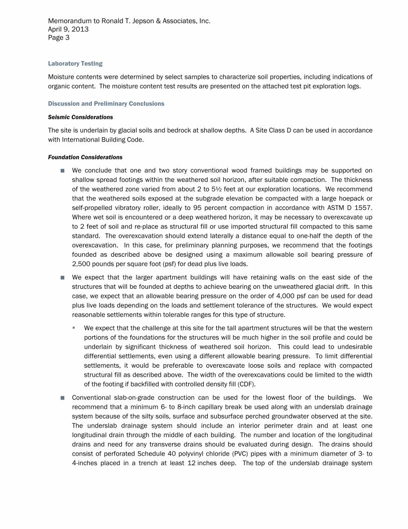
The 8 acre site has a typical slope of 20 to 22112 percent downward to the west as shown in the attached Site and Exploration Plan. The site is heavily forested with mature and young con ifer and deciduous trees with thick understory vegetation. An east to west trending stormwater drainage is located in the northern portion of the property. The stormwater in this area enters t he site f rom a culvert that crosses the Puget Street right-of-way. The property to the north is a designated wet land and was donated to the City. A buffer from the wetland is associated with proposed site development.
Groundwater seeps were also observed atthe ground surface in the eastern end of the Consolidation Avenue right-of-way to the south of the site, and also south and southwest of test pit TP-7.
Dlsclalmer: Any electron Jc form, facsimile or hard copy or the orlglnal document (email, text, table, and/or figure), If provided, and any attachments are only a copy of the orlglnal document. The original document Is stored by GeoEnglneers, Inc. and wlll serve as the offlclal document of record.
Memorandum to Ronald T. Jepson & Associates, Inc. April 9, 2013 Page 2
Subsurface Conditions
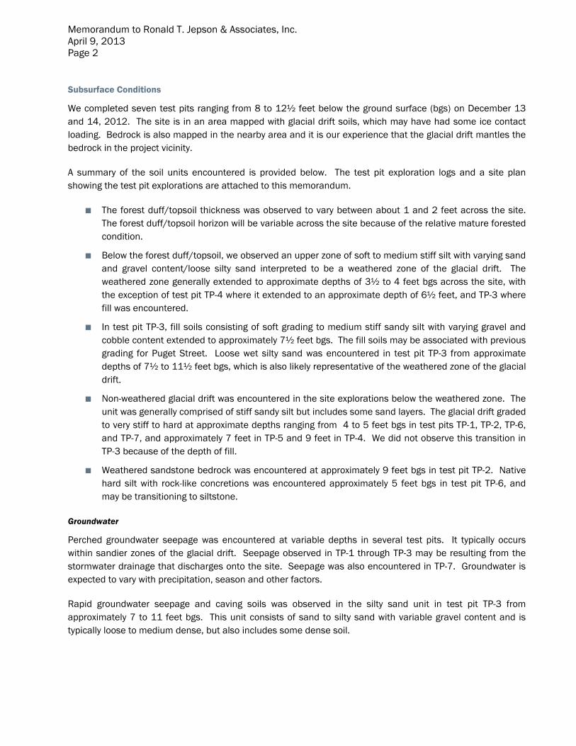
We completed seven test pits ranging from 8 to 12½ feet below the ground surface (bgs) on December 13 and 14, 2012. The site is in an area mapped with glacial drift soils, which may have had some ice contact loading. Bedrock is also mapped in the nearby area and it is our experience that the glacial drift mantles the bedrock in the project vicinity.
A summary of the soil units encountered is provided below. The test pit exploration logs and a site plan showing the test pit explorations are attached to this memorandum.
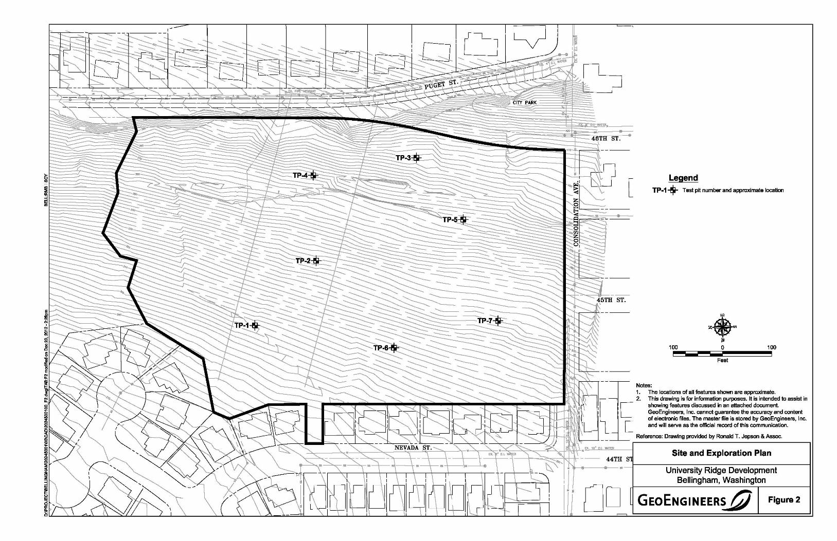
■ The forest duff/topsoil thickness was observed to vary between about 1 and 2 feet across the site. The forest duff/topsoil horizon will be variable across the site because of the relative mature forested condition.
■ Below the forest duff/topsoil, we observed an upper zone of soft to medium stiff silt with varying sand and gravel content/loose silty sand interpreted to be a weathered zone of the glacial drift. The weathered zone generally extended to approximate depths of 3½ to 4 feet bgs across the site, with the exception of test pit TP-4 where it extended to an approximate depth of 6½ feet, and TP-3 where fill was encountered.
■ In test pit TP-3, fill soils consisting of soft grading to medium stiff sandy silt with varying gravel and cobble content extended to approximately 7½ feet bgs. The fill soils may be associated with previous grading for Puget Street. Loose wet silty sand was encountered in test pit TP-3 from approximate depths of 7½ to 11½ feet bgs, which is also likely representative of the weathered zone of the glacial drift.
■ Non-weathered glacial drift was encountered in the site explorations below the weathered zone. The unit was generally comprised of stiff sandy silt but includes some sand layers. The glacial drift graded to very stiff to hard at approximate depths ranging from 4 to 5 feet bgs in test pits TP-1, TP-2, TP-6, and TP-7, and approximately 7 feet in TP-5 and 9 feet in TP-4. We did not observe this transition in TP-3 because of the depth of fill.
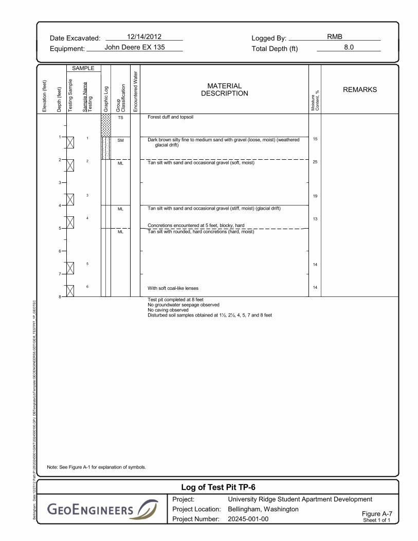
■ Weathered sandstone bedrock was encountered at approximately 9 feet bgs in test pit TP-2. Native hard silt with rock-like concretions was encountered approximately 5 feet bgs in test pit TP-6, and may be transitioning to siltstone.
Groundwater
Perched groundwater seepage was encountered at variable depths in several test pits. It typically occurs within sandier zones of the glacial drift. Seepage observed in TP-1 through TP-3 may be resulting from the stormwater drainage that discharges onto the site. Seepage was also encountered in TP-7. Groundwater is expected to vary with precipitation, season and other factors.
Rapid groundwater seepage and caving soils was observed in the silty sand unit in test pit TP-3 from approximately 7 to 11 feet bgs. This unit consists of sand to silty sand with variable gravel content and is typically loose to medium dense, but also includes some dense soil.
Memorandum to Ronald T. Jepson & Associates, Inc. April 9, 2013 Page 3
Laboratory Testing
Moisture contents were determined by select samples to characterize soil properties, including indications of organic content. The moisture content test results are presented on the attached test pit exploration logs.
Discussion and Preliminary Conclusions
Seismic Considerations
The site is underlain by glacial soils and bedrock at shallow depths. A Site Class D can be used in accordance with International Building Code.
Foundation Considerations
■ We conclude that one and two story conventional wood framed buildings may be supported on shallow spread footings within the weathered soil horizon, after suitable compaction. The thickness of the weathered zone varied from about 2 to 5½ feet at our exploration locations. We recommend that the weathered soils exposed at the subgrade elevation be compacted with a large hoepack or self-propelled vibratory roller, ideally to 95 percent compaction in accordance with ASTM D 1557. Where wet soil is encountered or a deep weathered horizon, it may be necessary to overexcavate up to 2 feet of soil and re-place as structural fill or use imported structural fill compacted to this same standard. The overexcavation should extend laterally a distance equal to one-half the depth of the overexcavation. In this case, for preliminary planning purposes, we recommend that the footings founded as described above be designed using a maximum allowable soil bearing pressure of 2,500 pounds per square foot (psf) for dead plus live loads.
■ We expect that the larger apartment buildings will have retaining walls on the east side of the structures that will be founded at depths to achieve bearing on the unweathered glacial drift. In this case, we expect that an allowable bearing pressure on the order of 4,000 psf can be used for dead plus live loads depending on the loads and settlement tolerance of the structures. We would expect reasonable settlements within tolerable ranges for this type of structure.
We expect that the challenge at this site for the tall apartment structures will be that the western portions of the foundations for the structures will be much higher in the soil profile and could be underlain by significant thickness of weathered soil horizon. This could lead to undesirable differential settlements, even using a different allowable bearing pressure. To limit differential settlements, it would be preferable to overexcavate loose soils and replace with compacted structural fill as described above. The width of the overexcavations could be limited to the width of the footing if backfilled with controlled density fill (CDF).
■ Conventional slab-on-grade construction can be used for the lowest floor of the buildings. We recommend that a minimum 6- to 8-inch capillary break be used along with an underslab drainage system because of the silty soils, surface and subsurface perched groundwater observed at the site. The underslab drainage system should include an interior perimeter drain and at least one longitudinal drain through the middle of each building. The number and location of the longitudinal drains and need for any transverse drains should be evaluated during design. The drains should consist of perforated Schedule 40 polyvinyl chloride (PVC) pipes with a minimum diameter of 3- to 4-inches placed in a trench at least 12 inches deep. The top of the underslab drainage system

Memorandum to Ronald T. Jepson & Associates, Inc. April 9, 2013 Page 4
trenches should coincide with the base of the capillary break layer. The underslab drainage system pipes should have adequate slope to allow positive drainage to the sump/gravity drain.
Stormwater and Drainage Considerations
■ Stormwater infiltration will not be feasible based on the relatively impermeable glacial soils and bedrock encountered in our test pit explorations. The site should be modeled using Class C soils for stormwater management. Therefore, stormwater detention vault(s) will be required.
■ We recommend that perimeter-footing drains be included around all buildings because of the presence of perched groundwater conditions. The perimeter footing drains should be lower than the ground surface elevation on the interior of the building.
■ We recommend under-slab drainage system below slabs-on-grade as described above.
■ Roadways should be constructed with an adequate free-draining subbase to protect the roadway from the seasonally perched groundwater. It is possible that upslope edge drains may be appropriate to intercept perched groundwater.
■ Any cuts into the weathered horizon at the site will likely intercept perched groundwater during the wet season. It may be necessary to install ditches, interceptor trench drains along cut areas or in other areas to intercept the shallow groundwater and route it to a suitable discharge during construction.
Earthwork and Field Performance
■ Typical stripping depths ranging from 1 to 2 feet deep are expected based on the explorations performed. Some deeper stripping may be required in areas of soft and/or wet soils, and with thick vegetation.
■ The glacial drift soils consist primarily of sandy silt with some silty sand and generally moisture sensitive and difficult to work with during wet weather. The moisture contents within the weathered zone ranged from 12 to 25 percent; we expect that the optimum moisture content may be close to about 10 percent for this material. It will be difficult to impossible to properly compact these soils in excessively wet conditions. Therefore, we conclude that the upper site soils will not be suitable as structural fill under wet conditions and will likely require aeration during grading even in the summer months. We recommend that the earthwork for the project be completed during the drier late summer/early fall months in order to minimize grading costs.
■ We expect that all of the soils encountered across the site can be removed with conventional excavating equipment. However, a large horsepower track-mounted excavator will be more efficient for deeper excavations. Large cobbles and boulders can occur within the glacial drift soils, but are sporadic. Sandstone was encountered at one location, and could be encountered at the site.
■ We recommend a maximum permanent slope inclination of 2H:1V in the upper native soils or in structural fill used to construct permanent slopes. It will be possible to use slopes as steep as 0.75H:1V where the stiff clay is encountered.
■ We expect that retaining systems will be appropriate for some grade transitions for the project. Rockeries can be used to face cuts up to about 6 to 8 feet high, preferably facing stiff native materials. We expect that mechanically stabilized earth (MSE) walls will be a cost-effective wall

Memorandum to Ronald T. Jepson & Associates, Inc. April 9, 2013 Page 5
system for higher roadway and parking lot fills to limit the downslope fill prism. These systems can consist of large blocks (Ultra Blocks, Redi Rock) or smaller modular blocks with geogrid reinforcing. Some facings use gravel and/or topsoil for vegetation (Hilfiker, Sierra) if desirable.
The transition along the eastern margin of the site should be carefully evaluated. It appears that significant fill may have been placed as part of the Puget Street construction. Based on the single test pit accomplished in this area, the fill is soft to medium stiff and the underlying weathered zone had significant groundwater seepage and caving soils.
■ Silt fencing and other techniques as appropriate should be used downslope from construction areas where obvious sediment transport routes exist, such as areas where the inclinations of slopes attenuate surface flow during wet weather. Disturbance of existing vegetation adjacent to the building envelope should be permanently stabilized with mulching, sod, or similar materials. These recommendations are intended to minimize the likelihood of erosion and sediment transport of surficial soils proximal to and on the steep slopes.
Limitations
We have prepared this memorandum of preliminary findings for the exclusive use of Ronald T. Jepson & Associates, Inc. and their authorized agents for the proposed housing project described herein.
This memorandum is a summary of existing information and preliminary design considerations and is not suitable for design. Within the limitations of scope, schedule and budget, our services have been executed in accordance with generally accepted practices in the field of geotechnical engineering in this area at the time this report was prepared. No warranty or other conditions, express or implied, should be understood.
Some additional collaboration with the design team will be appropriate to determine final design conclusions and recommendations.
RMB:JRG:tln
List of Figures:
Figure 2. Site Plan
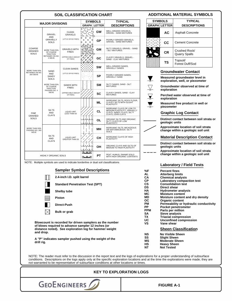
Figure A-1. Key to Explorations
Figures A-2 through A-8. Log of Test Pits
One copy submitted
Legend TP-1-$- Test pit number and approximate location
100 100 - ----Feet
Notes: 1. The locations of all features shown are approximate. 2. This drawing is for information purposes. It is intended to assist in
I showing features discussed in an attached document. L GeoEngineers, Inc. cannot guarantee the accuracy and content
of electronic files. The master file is stored by GeoEngineers, Inc.
[JI I
[ and will serve as the official record of this communication.
Reference: Drawing provided by Ronald T. Jepson &Assoc.
Site and Exploration Plan
University Ridge Development Bellingham, Washington
GEoENGINEERS t;J Figure 2

Shelby tube
ADDITIONAL MATERIAL SYMBOLS
GRAPH
Topsoil/Forest Duff/Sod
Direct-Push
Crushed Rock/Quarry Spalls
Blowcount is recorded for driven samplers as the numberof blows required to advance sampler 12 inches (ordistance noted). See exploration log for hammer weightand drop.
A "P" indicates sampler pushed using the weight of thedrill rig.
FIGURE A-1
2.4-inch I.D. split barrel
SYMBOLS TYPICAL
KEY TO EXPLORATION LOGS
CR
Bulk or grab
Piston
Standard Penetration Test (SPT)
DESCRIPTIONS
Laboratory / Field Tests
LETTER
TSGC
PT
OH
CH
MH
OL
GM
GP
GW
DESCRIPTIONSTYPICAL
LETTER
(APPRECIABLE AMOUNTOF FINES)
MAJOR DIVISIONS
POORLY-GRADED SANDS,GRAVELLY SAND
PEAT, HUMUS, SWAMP SOILSWITH HIGH ORGANIC CONTENTS
CLEAN SANDS
GRAVELS WITHFINES
CLEANGRAVELS
HIGHLY ORGANIC SOILS
SILTSAND
CLAYS
SILTSAND
CLAYS
SANDAND
SANDYSOILS
GRAVELAND
GRAVELLYSOILS
(LITTLE OR NO FINES)
FINEGRAINED
SOILS
COARSEGRAINED
SOILS
SW
MORE THAN 50%OF COARSEFRACTION
RETAINED ON NO.4 SIEVE
CL
WELL-GRADED SANDS,GRAVELLY SANDS
SILTY GRAVELS, GRAVEL - SAND- SILT MIXTURES
LIQUID LIMITGREATER THAN 50
SILTY SANDS, SAND - SILTMIXTURES
(APPRECIABLE AMOUNTOF FINES)
SOIL CLASSIFICATION CHART
LIQUID LIMITLESS THAN 50
SANDS WITHFINES
SP(LITTLE OR NO FINES)
ML
SC
SM
NOTE: Multiple symbols are used to indicate borderline or dual soil classifications
MORE THAN 50%OF COARSEFRACTION
PASSING NO. 4SIEVE
CLAYEY GRAVELS, GRAVEL -SAND - CLAY MIXTURES
CLAYEY SANDS, SAND - CLAYMIXTURES
INORGANIC SILTS, ROCK FLOUR,CLAYEY SILTS WITH SLIGHTPLASTICITY
ORGANIC SILTS AND ORGANICSILTY CLAYS OF LOWPLASTICITY
INORGANIC SILTS, MICACEOUSOR DIATOMACEOUS SILTYSOILS
ORGANIC CLAYS AND SILTS OFMEDIUM TO HIGH PLASTICITY
INORGANIC CLAYS OF HIGHPLASTICITY
MORE THAN 50%PASSING NO. 200
SIEVE
MORE THAN 50%RETAINED ON NO.
200 SIEVE
WELL-GRADED GRAVELS,GRAVEL - SAND MIXTURES
POORLY-GRADED GRAVELS,GRAVEL - SAND MIXTURES
INORGANIC CLAYS OF LOW TOMEDIUM PLASTICITY, GRAVELLYCLAYS, SANDY CLAYS, SILTYCLAYS, LEAN CLAYS
GRAPH
SYMBOLS
AC
CC Cement Concrete
Asphalt Concrete
Sampler Symbol Descriptions
Approximate location of soil stratachange within a geologic soil unit
No Visible SheenSlight SheenModerate SheenHeavy SheenNot Tested
NSSSMSHSNT
Measured free product in well orpiezometer
Perched water observed at time ofexploration
Groundwater observed at time ofexploration
Measured groundwater level inexploration, well, or piezometer
Sheen Classification
NOTE: The reader must refer to the discussion in the report text and the logs of explorations for a proper understanding of subsurfaceconditions. Descriptions on the logs apply only at the specific exploration locations and at the time the explorations were made; they arenot warranted to be representative of subsurface conditions at other locations or times.
Graphic Log Contact
Material Description Contact
Percent finesAtterberg limitsChemical analysisLaboratory compaction testConsolidation testDirect shearHydrometer analysisMoisture contentMoisture content and dry densityOrganic contentPermeability or hydraulic conductivityPocket penetrometerParts per millionSieve analysisTriaxial compressionUnconfined compressionVane shear
Distinct contact between soil strata orgeologic units
%FALCACPCSDSHAMCMDOCPMPPPPMSATXUCVS
Distinct contact between soil strata orgeologic units
Approximate location of soil stratachange within a geologic soil unit
Groundwater Contact

1
2
3
4
5
Forest duff and topsoil
Gray, tan and rust brown silt with sand, occasional gravel, cobbles andsand lenses (medium stiff, moist) (weathered glacial drift)
Gray and tan silt with sand, occasional gravel and cobbles (stiff, moist)(glacial drift)
Gray and tan silt with fine sand lenses, occasional gravel and cobbles(hard, moist)
Gray sandy silt with sand lenses, occasional gravel and cobbles (hard,moist)
Boulder encountered
Test pit completed at 10 feetSlow groundwater seepage observed at 2½ and 4 feetNo caving observedDisturbed soil samples obtained at 2, 4, 5, 7, and 10 feet
TS
ML
ML
ML
ML
22
18
19
11
Note: See Figure A-1 for explanation of symbols.
Bel
lingh
am:
Dat
e:12
/27/
12 P
ath:
P:\
20\2
0245
001\
GIN
T\2
0245
0010
0.G
PJ
DB
Tem
plat
e/Li
bTem
plat
e:G
EO
EN
GIN
EE
RS
8.G
DT
/GE
I8_T
ES
TP
IT_1
P_G
EO
TE
C
Date Excavated:
Equipment:
Logged By:12/13/2012
John Deere EX 135 Total Depth (ft)
RMB
10.0
Tes
ting
Sam
ple
Dep
th (
feet
)
1
2
3
4
5
6
7
8
9
10
SAMPLE
Gra
phic
Log
Ele
vatio
n (f
eet)
Sam
ple
Nam
eT
estin
gMATERIAL
DESCRIPTION
Gro
upC
lass
ifica
tion
Enc
ount
ered
Wat
er
Moi
stur
eC
onte
nt,
% REMARKS
Log of Test Pit TP-1University Ridge Student Apartment Development
Bellingham, Washington
20245-001-00
Project:
Project Location:
Project Number:Figure A-2Sheet 1 of 1

1
2
3
4
5
Forest duff and topsoil
Brown sandy silt with occasional charcoal fragments and rootlets (mediumstiff, moist) (weathered glacial drift)
Brown sandy silt with sand lenses, occasional gravel and cobbles (stiff,moist) (glacial drift)
Brown silty fine to medium sand with occasional gravel (medium dense,moist) (decomposed sandstone)
Sandstone concretions encountered
Brown weathered sandstone bedrock
Test pit completed at 10 feetSlow groundwater seepage observed at 3 feetNo caving observedDisturbed soil samples obtained at 1½, 3½, 5, 7½ and 9½ feet
TS
ML
ML
SM
SNDSTN
13
14
11
13
Note: See Figure A-1 for explanation of symbols.
Bel
lingh
am:
Dat
e:12
/27/
12 P
ath:
P:\
20\2
0245
001\
GIN
T\2
0245
0010
0.G
PJ
DB
Tem
plat
e/Li
bTem
plat
e:G
EO
EN
GIN
EE
RS
8.G
DT
/GE
I8_T
ES
TP
IT_1
P_G
EO
TE
C
Date Excavated:
Equipment:
Logged By:12/13/2012
John Deere EX 135 Total Depth (ft)
RMB
10.0
Tes
ting
Sam
ple
Dep
th (
feet
)
1
2
3
4
5
6
7
8
9
10
SAMPLE
Gra
phic
Log
Ele
vatio
n (f
eet)
Sam
ple
Nam
eT
estin
gMATERIAL
DESCRIPTION
Gro
upC
lass
ifica
tion
Enc
ount
ered
Wat
er
Moi
stur
eC
onte
nt,
% REMARKS
Log of Test Pit TP-2University Ridge Student Apartment Development
Bellingham, Washington
20245-001-00
Project:
Project Location:
Project Number:Figure A-3Sheet 1 of 1
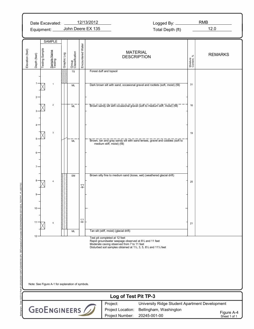
1
2
3
4
5
Forest duff and topsoil
Dark brown silt with sand, occasional gravel and rootlets (soft, moist) (fill)
Brown sandy silt with occasional gravel (soft to medium stiff, moist) (fill)
Brown, tan and gray sandy silt with sand lenses, gravel and cobbles (soft tomedium stiff, moist) (fill)
Brown silty fine to medium sand (loose, wet) (weathered glacial drift)
Tan silt (stiff, moist) (glacial drift)
Test pit completed at 12 feetRapid groundwater seepage observed at 8½ and 11 feetModerate caving observed from 7 to 11 feetDisturbed soil samples obtained at 1½, 3, 5, 8½ and 11½ feet
TS
ML
ML
ML
SM
ML
31
16
19
25
21
Note: See Figure A-1 for explanation of symbols.
Bel
lingh
am:
Dat
e:12
/27/
12 P
ath:
P:\
20\2
0245
001\
GIN
T\2
0245
0010
0.G
PJ
DB
Tem
plat
e/Li
bTem
plat
e:G
EO
EN
GIN
EE
RS
8.G
DT
/GE
I8_T
ES
TP
IT_1
P_G
EO
TE
C
Date Excavated:
Equipment:
Logged By:12/13/2012
John Deere EX 135 Total Depth (ft)
RMB
12.0
Tes
ting
Sam
ple
Dep
th (
feet
)
1
2
3
4
5
6
7
8
9
10
11
12
SAMPLE
Gra
phic
Log
Ele
vatio
n (f
eet)
Sam
ple
Nam
eT
estin
gMATERIAL
DESCRIPTION
Gro
upC
lass
ifica
tion
Enc
ount
ered
Wat
er
Moi
stur
eC
onte
nt,
% REMARKS
Log of Test Pit TP-3University Ridge Student Apartment Development
Bellingham, Washington
20245-001-00
Project:
Project Location:
Project Number:Figure A-4Sheet 1 of 1

1
2
3
4
5
6
Forest duff and topsoil
Brown sandy silt with gravel and cobbles (soft, moist) (weathered glacialdrift)
Brown sandy silt with gravel, cobbles, and sand lenses (medium stiff, moist)
Brown silty fine to medium sand with occasional gravel (loose, moist)
Brown sandy silt with gravel, cobbles and occasional boulders (stiff, moist)(glacial drift)
Brown sandy silt with occasional cobbles and boulders (very stiff to hard)
Test pit completed at 11 feetNo groundwater seepage observedNo caving observedDisturbed soil samples obtained at 1½, 2½, 6, 7½, 9 and 11 feet
TS
ML
ML
SM
ML
ML
17
11
22
15
13
Note: See Figure A-1 for explanation of symbols.
Bel
lingh
am:
Dat
e:12
/27/
12 P
ath:
P:\
20\2
0245
001\
GIN
T\2
0245
0010
0.G
PJ
DB
Tem
plat
e/Li
bTem
plat
e:G
EO
EN
GIN
EE
RS
8.G
DT
/GE
I8_T
ES
TP
IT_1
P_G
EO
TE
C
Date Excavated:
Equipment:
Logged By:12/13/2012
John Deere EX 135 Total Depth (ft)
RMB
11.0
Tes
ting
Sam
ple
Dep
th (
feet
)
1
2
3
4
5
6
7
8
9
10
11
SAMPLE
Gra
phic
Log
Ele
vatio
n (f
eet)
Sam
ple
Nam
eT
estin
gMATERIAL
DESCRIPTION
Gro
upC
lass
ifica
tion
Enc
ount
ered
Wat
er
Moi
stur
eC
onte
nt,
% REMARKS
Log of Test Pit TP-4University Ridge Student Apartment Development
Bellingham, Washington
20245-001-00
Project:
Project Location:
Project Number:Figure A-5Sheet 1 of 1

1
2
3
4
Forest duff and topsoil
Brown sandy silt with occasional gravel (medium stiff, moist) (weatheredglacial drift)
Brown sandy silt with gravel and occasional cobbles (stiff, moist) (glacialdrift)
Becomes very stiff
Moist to wet sand layer observed from 10 to 11 feet
Test pit comnpleted at 12 feetNo groundwater seepage observedNo caving observedDisturbed soil samples obtained at 2, 4, 7 and 12 feet
TS
ML
ML
ML
12
15
18
Note: See Figure A-1 for explanation of symbols.
Bel
lingh
am:
Dat
e:12
/27/
12 P
ath:
P:\
20\2
0245
001\
GIN
T\2
0245
0010
0.G
PJ
DB
Tem
plat
e/Li
bTem
plat
e:G
EO
EN
GIN
EE
RS
8.G
DT
/GE
I8_T
ES
TP
IT_1
P_G
EO
TE
C
Date Excavated:
Equipment:
Logged By:12/13/2012
John Deere EX 135 Total Depth (ft)
RMB
12.0
Tes
ting
Sam
ple
Dep
th (
feet
)
1
2
3
4
5
6
7
8
9
10
11
12
SAMPLE
Gra
phic
Log
Ele
vatio
n (f
eet)
Sam
ple
Nam
eT
estin
gMATERIAL
DESCRIPTION
Gro
upC
lass
ifica
tion
Enc
ount
ered
Wat
er
Moi
stur
eC
onte
nt,
% REMARKS
Log of Test Pit TP-5University Ridge Student Apartment Development
Bellingham, Washington
20245-001-00
Project:
Project Location:
Project Number:Figure A-6Sheet 1 of 1

1
2
3
4
5
6
Forest duff and topsoil
Dark brown silty fine to medium sand with gravel (loose, moist) (weatheredglacial drift)
Tan silt with sand and occasional gravel (soft, moist)
Tan silt with sand and occasional gravel (stiff, moist) (glacial drift)
Concretions encountered at 5 feet, blocky, hardTan silt with rounded, hard concretions (hard, moist)
With soft coal-like lenses
Test pit completed at 8 feetNo groundwater seepage observedNo caving observedDisturbed soil samples obtained at 1½, 2½, 4, 5, 7 and 8 feet
TS
SM
ML
ML
ML
15
25
19
13
14
14
Note: See Figure A-1 for explanation of symbols.
Bel
lingh
am:
Dat
e:12
/27/
12 P
ath:
P:\
20\2
0245
001\
GIN
T\2
0245
0010
0.G
PJ
DB
Tem
plat
e/Li
bTem
plat
e:G
EO
EN
GIN
EE
RS
8.G
DT
/GE
I8_T
ES
TP
IT_1
P_G
EO
TE
C
Date Excavated:
Equipment:
Logged By:12/14/2012
John Deere EX 135 Total Depth (ft)
RMB
8.0
Tes
ting
Sam
ple
Dep
th (
feet
)
1
2
3
4
5
6
7
8
SAMPLE
Gra
phic
Log
Ele
vatio
n (f
eet)
Sam
ple
Nam
eT
estin
gMATERIAL
DESCRIPTION
Gro
upC
lass
ifica
tion
Enc
ount
ered
Wat
er
Moi
stur
eC
onte
nt,
% REMARKS
Log of Test Pit TP-6University Ridge Student Apartment Development
Bellingham, Washington
20245-001-00
Project:
Project Location:
Project Number:Figure A-7Sheet 1 of 1

1
2
3
4
5
Forest duff and topsoil
Brown silty fine to medium sand with gravel (loose, moist to wet)(weathered glacial drift)
Tan, gray and reddish brown sandy silt with sand lenses and occasionalgravel (medium stiff, moist)
Brown sandy silt with occasional gravel and cobbles (hard, moist) (glacialdrift)
Test pit completed at 10 feetSlow groundwater seepage observed from 0 to 1½ and at 4 feetNo caving observedDisturbed soil samples obtained at 2, 3½, 4½, 7 and 10 feet
TS
SM
ML
ML
11
24
13
12
12
Note: See Figure A-1 for explanation of symbols.
Bel
lingh
am:
Dat
e:12
/27/
12 P
ath:
P:\
20\2
0245
001\
GIN
T\2
0245
0010
0.G
PJ
DB
Tem
plat
e/Li
bTem
plat
e:G
EO
EN
GIN
EE
RS
8.G
DT
/GE
I8_T
ES
TP
IT_1
P_G
EO
TE
C
Date Excavated:
Equipment:
Logged By:12/14/2012
John Deere EX 135 Total Depth (ft)
RMB
10.0
Tes
ting
Sam
ple
Dep
th (
feet
)
1
2
3
4
5
6
7
8
9
10
SAMPLE
Gra
phic
Log
Ele
vatio
n (f
eet)
Sam
ple
Nam
eT
estin
gMATERIAL
DESCRIPTION
Gro
upC
lass
ifica
tion
Enc
ount
ered
Wat
er
Moi
stur
eC
onte
nt,
% REMARKS
Log of Test Pit TP-7University Ridge Student Apartment Development
Bellingham, Washington
20245-001-00
Project:
Project Location:
Project Number:Figure A-8Sheet 1 of 1

GeoENGINEERS CJ Memorandum
600 Dupont Street, Bellingham, Washington 98225, Telephone: 360.647.1510, Fax: 360.647.5044 www.geoenglneers.com
To: Ron Jepson of Rona ld T. Jepson & Associates, Inc.
From: Ron Bek, LG
Date:
Fiie:
Subject:
J. Robert Gordo
April 9, 2013
20245-001-00
Soil Conditions and Preliminary Findings
NOT FOR CONSTRUCTION
Proposed University Ridge Student Apartment Development Bell ingham, Washington
Int roduction and Project Understanding
The purpose of this memorandum is to present preliminary geotechnical results related to the referenced
project. We have completed the field exploration program and the laboratory testing program, and performed some preliminary analyses. Our geotechnical services were completed in general accordance with our proposal dated October 22, 2012.
Our understanding of the project is based on a preliminary site plan provided by Ronald T. Jepson & Associates, Inc. and conversations with representatives of the design team. Additional details will be necessary to prepare our f inal report. We understand the proposed project will include the following
elements:
• The proposed development will consist of several multiple story (potentially up to four or five) wood framed buildings with associated infrastructure. Because of the sloping ground, we anticipate that
the east side of the buildings will have a retaining wall and then a stepped foundation will be used in the east-west direction.
• The project will require considerable grading. Use of on-site materia l for fill placement is desirable.
• Additiona l Improvements will likely include potentially tall retaining wal ls to accommodate site slopes and new roadways/driveways. We understand a wall or slope will be required along the east side of the site development.
• A drainage and stormwater plan has not been prepared as yet; however, stormwater vaults are envisioned.
Surface Condit ions
The 11 acre site has a typical slope of 20 to 22112 percent downward to the west as shown in the attached Site and Exploration Plan. The site is heavily forested with mature and young conifer and deciduous trees with thick un'derstory vegetation. An east to west trending stormwater drainage is located In the northern portion of the property. The stormwater in this area enters the site from a culvert that crosses the Puget Street right-of-way. The property to the north is a designated wetland and was donated to the City. A buffer from the wetland is associated with proposed site development.
Groundwater seeps were also observed at the ground surface in the eastern end of the Consolidation Avenue right-of-way to the south of the site, and also south and southwest of test pit TP-7.
Disclaimer: Any electronic rorm, facsimile or hard copy of the original document (email, text, table, and/or figure), If provided, and any attachments are only a copy of the original document. The original document Is stored by Ge0Englneers1 Inc. and will serve as the official document of record.

Memorandum to Ronald T. Jepson & Associates, Inc. April 9, 2013 Page 2
Subsurface Conditions
We completed seven test pits ranging from 8 to 12½ feet below the ground surface (bgs) on December 13 and 14, 2012. The site is in an area mapped with glacial drift soils, which may have had some ice contact loading. Bedrock is also mapped in the nearby area and it is our experience that the glacial drift mantles the bedrock in the project vicinity.
A summary of the soil units encountered is provided below. The test pit exploration logs and a site plan showing the test pit explorations are attached to this memorandum.
■ The forest duff/topsoil thickness was observed to vary between about 1 and 2 feet across the site. The forest duff/topsoil horizon will be variable across the site because of the relative mature forested condition.
■ Below the forest duff/topsoil, we observed an upper zone of soft to medium stiff silt with varying sand and gravel content/loose silty sand interpreted to be a weathered zone of the glacial drift. The weathered zone generally extended to approximate depths of 3½ to 4 feet bgs across the site, with the exception of test pit TP-4 where it extended to an approximate depth of 6½ feet, and TP-3 where fill was encountered.
■ In test pit TP-3, fill soils consisting of soft grading to medium stiff sandy silt with varying gravel and cobble content extended to approximately 7½ feet bgs. The fill soils may be associated with previous grading for Puget Street. Loose wet silty sand was encountered in test pit TP-3 from approximate depths of 7½ to 11½ feet bgs, which is also likely representative of the weathered zone of the glacial drift.
■ Non-weathered glacial drift was encountered in the site explorations below the weathered zone. The unit was generally comprised of stiff sandy silt but includes some sand layers. The glacial drift graded to very stiff to hard at approximate depths ranging from 4 to 5 feet bgs in test pits TP-1, TP-2, TP-6, and TP-7, and approximately 7 feet in TP-5 and 9 feet in TP-4. We did not observe this transition in TP-3 because of the depth of fill.
■ Weathered sandstone bedrock was encountered at approximately 9 feet bgs in test pit TP-2. Native hard silt with rock-like concretions was encountered approximately 5 feet bgs in test pit TP-6, and may be transitioning to siltstone.
Groundwater
Perched groundwater seepage was encountered at variable depths in several test pits. It typically occurs within sandier zones of the glacial drift. Seepage observed in TP-1 through TP-3 may be resulting from the stormwater drainage that discharges onto the site. Seepage was also encountered in TP-7. Groundwater is expected to vary with precipitation, season and other factors.
Rapid groundwater seepage and caving soils was observed in the silty sand unit in test pit TP-3 from approximately 7 to 11 feet bgs. This unit consists of sand to silty sand with variable gravel content and is typically loose to medium dense, but also includes some dense soil.

Memorandum to Ronald T. Jepson & Associates, Inc. April 9, 2013 Page 3
Laboratory Testing
Moisture contents were determined by select samples to characterize soil properties, including indications of organic content. The moisture content test results are presented on the attached test pit exploration logs.
Discussion and Preliminary Conclusions
Seismic Considerations
The site is underlain by glacial soils and bedrock at shallow depths. A Site Class D can be used in accordance with International Building Code.
Foundation Considerations
■ We conclude that one and two story conventional wood framed buildings may be supported on shallow spread footings within the weathered soil horizon, after suitable compaction. The thickness of the weathered zone varied from about 2 to 5½ feet at our exploration locations. We recommend that the weathered soils exposed at the subgrade elevation be compacted with a large hoepack or self-propelled vibratory roller, ideally to 95 percent compaction in accordance with ASTM D 1557. Where wet soil is encountered or a deep weathered horizon, it may be necessary to overexcavate up to 2 feet of soil and re-place as structural fill or use imported structural fill compacted to this same standard. The overexcavation should extend laterally a distance equal to one-half the depth of the overexcavation. In this case, for preliminary planning purposes, we recommend that the footings founded as described above be designed using a maximum allowable soil bearing pressure of 2,500 pounds per square foot (psf) for dead plus live loads.
■ We expect that the larger apartment buildings will have retaining walls on the east side of the structures that will be founded at depths to achieve bearing on the unweathered glacial drift. In this case, we expect that an allowable bearing pressure on the order of 4,000 psf can be used for dead plus live loads depending on the loads and settlement tolerance of the structures. We would expect reasonable settlements within tolerable ranges for this type of structure.
We expect that the challenge at this site for the tall apartment structures will be that the western portions of the foundations for the structures will be much higher in the soil profile and could be underlain by significant thickness of weathered soil horizon. This could lead to undesirable differential settlements, even using a different allowable bearing pressure. To limit differential settlements, it would be preferable to overexcavate loose soils and replace with compacted structural fill as described above. The width of the overexcavations could be limited to the width of the footing if backfilled with controlled density fill (CDF).
■ Conventional slab-on-grade construction can be used for the lowest floor of the buildings. We recommend that a minimum 6- to 8-inch capillary break be used along with an underslab drainage system because of the silty soils, surface and subsurface perched groundwater observed at the site. The underslab drainage system should include an interior perimeter drain and at least one longitudinal drain through the middle of each building. The number and location of the longitudinal drains and need for any transverse drains should be evaluated during design. The drains should consist of perforated Schedule 40 polyvinyl chloride (PVC) pipes with a minimum diameter of 3- to 4-inches placed in a trench at least 12 inches deep. The top of the underslab drainage system

Memorandum to Ronald T. Jepson & Associates, Inc. April 9, 2013 Page 4
trenches should coincide with the base of the capillary break layer. The underslab drainage system pipes should have adequate slope to allow positive drainage to the sump/gravity drain.
Stormwater and Drainage Considerations
■ Stormwater infiltration will not be feasible based on the relatively impermeable glacial soils and bedrock encountered in our test pit explorations. The site should be modeled using Class C soils for stormwater management. Therefore, stormwater detention vault(s) will be required.
■ We recommend that perimeter-footing drains be included around all buildings because of the presence of perched groundwater conditions. The perimeter footing drains should be lower than the ground surface elevation on the interior of the building.
■ We recommend under-slab drainage system below slabs-on-grade as described above.
■ Roadways should be constructed with an adequate free-draining subbase to protect the roadway from the seasonally perched groundwater. It is possible that upslope edge drains may be appropriate to intercept perched groundwater.
■ Any cuts into the weathered horizon at the site will likely intercept perched groundwater during the wet season. It may be necessary to install ditches, interceptor trench drains along cut areas or in other areas to intercept the shallow groundwater and route it to a suitable discharge during construction.
Earthwork and Field Performance
■ Typical stripping depths ranging from 1 to 2 feet deep are expected based on the explorations performed. Some deeper stripping may be required in areas of soft and/or wet soils, and with thick vegetation.
■ The glacial drift soils consist primarily of sandy silt with some silty sand and generally moisture sensitive and difficult to work with during wet weather. The moisture contents within the weathered zone ranged from 12 to 25 percent; we expect that the optimum moisture content may be close to about 10 percent for this material. It will be difficult to impossible to properly compact these soils in excessively wet conditions. Therefore, we conclude that the upper site soils will not be suitable as structural fill under wet conditions and will likely require aeration during grading even in the summer months. We recommend that the earthwork for the project be completed during the drier late summer/early fall months in order to minimize grading costs.
■ We expect that all of the soils encountered across the site can be removed with conventional excavating equipment. However, a large horsepower track-mounted excavator will be more efficient for deeper excavations. Large cobbles and boulders can occur within the glacial drift soils, but are sporadic. Sandstone was encountered at one location, and could be encountered at the site.
■ We recommend a maximum permanent slope inclination of 2H:1V in the upper native soils or in structural fill used to construct permanent slopes. It will be possible to use slopes as steep as 0.75H:1V where the stiff clay is encountered.
■ We expect that retaining systems will be appropriate for some grade transitions for the project. Rockeries can be used to face cuts up to about 6 to 8 feet high, preferably facing stiff native materials. We expect that mechanically stabilized earth (MSE) walls will be a cost-effective wall

Memorandum to Ronald T. Jepson & Associates, Inc. April 9, 2013 Page 5
system for higher roadway and parking lot fills to limit the downslope fill prism. These systems can consist of large blocks (Ultra Blocks, Redi Rock) or smaller modular blocks with geogrid reinforcing. Some facings use gravel and/or topsoil for vegetation (Hilfiker, Sierra) if desirable.
The transition along the eastern margin of the site should be carefully evaluated. It appears that significant fill may have been placed as part of the Puget Street construction. Based on the single test pit accomplished in this area, the fill is soft to medium stiff and the underlying weathered zone had significant groundwater seepage and caving soils.
■ Silt fencing and other techniques as appropriate should be used downslope from construction areas where obvious sediment transport routes exist, such as areas where the inclinations of slopes attenuate surface flow during wet weather. Disturbance of existing vegetation adjacent to the building envelope should be permanently stabilized with mulching, sod, or similar materials. These recommendations are intended to minimize the likelihood of erosion and sediment transport of surficial soils proximal to and on the steep slopes.
Limitations
We have prepared this memorandum of preliminary findings for the exclusive use of Ronald T. Jepson & Associates, Inc. and their authorized agents for the proposed housing project described herein.
This memorandum is a summary of existing information and preliminary design considerations and is not suitable for design. Within the limitations of scope, schedule and budget, our services have been executed in accordance with generally accepted practices in the field of geotechnical engineering in this area at the time this report was prepared. No warranty or other conditions, express or implied, should be understood.
Some additional collaboration with the design team will be appropriate to determine final design conclusions and recommendations.
RMB:JRG:tln
List of Figures:
Figure 2. Site Plan
Figure A-1. Key to Explorations
Figures A-2 through A-8. Log of Test Pits
One copy submitted

Legend TP-1-$- Test pit number and approximate location
100 100 - ----Feet
Notes: 1. The locations of all features shown are approximate. 2. This drawing is for information purposes. It is intended to assist in
I showing features discussed in an attached document. L GeoEngineers, Inc. cannot guarantee the accuracy and content
of electronic files. The master file is stored by GeoEngineers, Inc.
[JI I
[ and will serve as the official record of this communication.
Reference: Drawing provided by Ronald T. Jepson &Assoc.
Site and Exploration Plan
University Ridge Development Bellingham, Washington
GEoENGINEERS t;J Figure 2
Shelby tube
ADDITIONAL MATERIAL SYMBOLS
GRAPH
Topsoil/Forest Duff/Sod
Direct-Push
Crushed Rock/Quarry Spalls
Blowcount is recorded for driven samplers as the numberof blows required to advance sampler 12 inches (ordistance noted). See exploration log for hammer weightand drop.
A "P" indicates sampler pushed using the weight of thedrill rig.
FIGURE A-1
2.4-inch I.D. split barrel
SYMBOLS TYPICAL
KEY TO EXPLORATION LOGS
CR
Bulk or grab
Piston
Standard Penetration Test (SPT)
DESCRIPTIONS
Laboratory / Field Tests
LETTER
TSGC
PT
OH
CH
MH
OL
GM
GP
GW
DESCRIPTIONSTYPICAL
LETTER
(APPRECIABLE AMOUNTOF FINES)
MAJOR DIVISIONS
POORLY-GRADED SANDS,GRAVELLY SAND
PEAT, HUMUS, SWAMP SOILSWITH HIGH ORGANIC CONTENTS
CLEAN SANDS
GRAVELS WITHFINES
CLEANGRAVELS
HIGHLY ORGANIC SOILS
SILTSAND
CLAYS
SILTSAND
CLAYS
SANDAND
SANDYSOILS
GRAVELAND
GRAVELLYSOILS
(LITTLE OR NO FINES)
FINEGRAINED
SOILS
COARSEGRAINED
SOILS
SW
MORE THAN 50%OF COARSEFRACTION
RETAINED ON NO.4 SIEVE
CL
WELL-GRADED SANDS,GRAVELLY SANDS
SILTY GRAVELS, GRAVEL - SAND- SILT MIXTURES
LIQUID LIMITGREATER THAN 50
SILTY SANDS, SAND - SILTMIXTURES
(APPRECIABLE AMOUNTOF FINES)
SOIL CLASSIFICATION CHART
LIQUID LIMITLESS THAN 50
SANDS WITHFINES
SP(LITTLE OR NO FINES)
ML
SC
SM
NOTE: Multiple symbols are used to indicate borderline or dual soil classifications
MORE THAN 50%OF COARSEFRACTION
PASSING NO. 4SIEVE
CLAYEY GRAVELS, GRAVEL -SAND - CLAY MIXTURES
CLAYEY SANDS, SAND - CLAYMIXTURES
INORGANIC SILTS, ROCK FLOUR,CLAYEY SILTS WITH SLIGHTPLASTICITY
ORGANIC SILTS AND ORGANICSILTY CLAYS OF LOWPLASTICITY
INORGANIC SILTS, MICACEOUSOR DIATOMACEOUS SILTYSOILS
ORGANIC CLAYS AND SILTS OFMEDIUM TO HIGH PLASTICITY
INORGANIC CLAYS OF HIGHPLASTICITY
MORE THAN 50%PASSING NO. 200
SIEVE
MORE THAN 50%RETAINED ON NO.
200 SIEVE
WELL-GRADED GRAVELS,GRAVEL - SAND MIXTURES
POORLY-GRADED GRAVELS,GRAVEL - SAND MIXTURES
INORGANIC CLAYS OF LOW TOMEDIUM PLASTICITY, GRAVELLYCLAYS, SANDY CLAYS, SILTYCLAYS, LEAN CLAYS
GRAPH
SYMBOLS
AC
CC Cement Concrete
Asphalt Concrete
Sampler Symbol Descriptions
Approximate location of soil stratachange within a geologic soil unit
No Visible SheenSlight SheenModerate SheenHeavy SheenNot Tested
NSSSMSHSNT
Measured free product in well orpiezometer
Perched water observed at time ofexploration
Groundwater observed at time ofexploration
Measured groundwater level inexploration, well, or piezometer
Sheen Classification
NOTE: The reader must refer to the discussion in the report text and the logs of explorations for a proper understanding of subsurfaceconditions. Descriptions on the logs apply only at the specific exploration locations and at the time the explorations were made; they arenot warranted to be representative of subsurface conditions at other locations or times.
Graphic Log Contact
Material Description Contact
Percent finesAtterberg limitsChemical analysisLaboratory compaction testConsolidation testDirect shearHydrometer analysisMoisture contentMoisture content and dry densityOrganic contentPermeability or hydraulic conductivityPocket penetrometerParts per millionSieve analysisTriaxial compressionUnconfined compressionVane shear
Distinct contact between soil strata orgeologic units
%FALCACPCSDSHAMCMDOCPMPPPPMSATXUCVS
Distinct contact between soil strata orgeologic units
Approximate location of soil stratachange within a geologic soil unit
Groundwater Contact

1
2
3
4
5
Forest duff and topsoil
Gray, tan and rust brown silt with sand, occasional gravel, cobbles andsand lenses (medium stiff, moist) (weathered glacial drift)
Gray and tan silt with sand, occasional gravel and cobbles (stiff, moist)(glacial drift)
Gray and tan silt with fine sand lenses, occasional gravel and cobbles(hard, moist)
Gray sandy silt with sand lenses, occasional gravel and cobbles (hard,moist)
Boulder encountered
Test pit completed at 10 feetSlow groundwater seepage observed at 2½ and 4 feetNo caving observedDisturbed soil samples obtained at 2, 4, 5, 7, and 10 feet
TS
ML
ML
ML
ML
22
18
19
11
Note: See Figure A-1 for explanation of symbols.
Bel
lingh
am:
Dat
e:12
/27/
12 P
ath:
P:\
20\2
0245
001\
GIN
T\2
0245
0010
0.G
PJ
DB
Tem
plat
e/Li
bTem
plat
e:G
EO
EN
GIN
EE
RS
8.G
DT
/GE
I8_T
ES
TP
IT_1
P_G
EO
TE
C
Date Excavated:
Equipment:
Logged By:12/13/2012
John Deere EX 135 Total Depth (ft)
RMB
10.0
Tes
ting
Sam
ple
Dep
th (
feet
)
1
2
3
4
5
6
7
8
9
10
SAMPLE
Gra
phic
Log
Ele
vatio
n (f
eet)
Sam
ple
Nam
eT
estin
gMATERIAL
DESCRIPTION
Gro
upC
lass
ifica
tion
Enc
ount
ered
Wat
er
Moi
stur
eC
onte
nt,
% REMARKS
Log of Test Pit TP-1University Ridge Student Apartment Development
Bellingham, Washington
20245-001-00
Project:
Project Location:
Project Number:Figure A-2Sheet 1 of 1

1
2
3
4
5
Forest duff and topsoil
Brown sandy silt with occasional charcoal fragments and rootlets (mediumstiff, moist) (weathered glacial drift)
Brown sandy silt with sand lenses, occasional gravel and cobbles (stiff,moist) (glacial drift)
Brown silty fine to medium sand with occasional gravel (medium dense,moist) (decomposed sandstone)
Sandstone concretions encountered
Brown weathered sandstone bedrock
Test pit completed at 10 feetSlow groundwater seepage observed at 3 feetNo caving observedDisturbed soil samples obtained at 1½, 3½, 5, 7½ and 9½ feet
TS
ML
ML
SM
SNDSTN
13
14
11
13
Note: See Figure A-1 for explanation of symbols.
Bel
lingh
am:
Dat
e:12
/27/
12 P
ath:
P:\
20\2
0245
001\
GIN
T\2
0245
0010
0.G
PJ
DB
Tem
plat
e/Li
bTem
plat
e:G
EO
EN
GIN
EE
RS
8.G
DT
/GE
I8_T
ES
TP
IT_1
P_G
EO
TE
C
Date Excavated:
Equipment:
Logged By:12/13/2012
John Deere EX 135 Total Depth (ft)
RMB
10.0
Tes
ting
Sam
ple
Dep
th (
feet
)
1
2
3
4
5
6
7
8
9
10
SAMPLE
Gra
phic
Log
Ele
vatio
n (f
eet)
Sam
ple
Nam
eT
estin
gMATERIAL
DESCRIPTION
Gro
upC
lass
ifica
tion
Enc
ount
ered
Wat
er
Moi
stur
eC
onte
nt,
% REMARKS
Log of Test Pit TP-2University Ridge Student Apartment Development
Bellingham, Washington
20245-001-00
Project:
Project Location:
Project Number:Figure A-3Sheet 1 of 1

1
2
3
4
5
Forest duff and topsoil
Dark brown silt with sand, occasional gravel and rootlets (soft, moist) (fill)
Brown sandy silt with occasional gravel (soft to medium stiff, moist) (fill)
Brown, tan and gray sandy silt with sand lenses, gravel and cobbles (soft tomedium stiff, moist) (fill)
Brown silty fine to medium sand (loose, wet) (weathered glacial drift)
Tan silt (stiff, moist) (glacial drift)
Test pit completed at 12 feetRapid groundwater seepage observed at 8½ and 11 feetModerate caving observed from 7 to 11 feetDisturbed soil samples obtained at 1½, 3, 5, 8½ and 11½ feet
TS
ML
ML
ML
SM
ML
31
16
19
25
21
Note: See Figure A-1 for explanation of symbols.
Bel
lingh
am:
Dat
e:12
/27/
12 P
ath:
P:\
20\2
0245
001\
GIN
T\2
0245
0010
0.G
PJ
DB
Tem
plat
e/Li
bTem
plat
e:G
EO
EN
GIN
EE
RS
8.G
DT
/GE
I8_T
ES
TP
IT_1
P_G
EO
TE
C
Date Excavated:
Equipment:
Logged By:12/13/2012
John Deere EX 135 Total Depth (ft)
RMB
12.0
Tes
ting
Sam
ple
Dep
th (
feet
)
1
2
3
4
5
6
7
8
9
10
11
12
SAMPLE
Gra
phic
Log
Ele
vatio
n (f
eet)
Sam
ple
Nam
eT
estin
gMATERIAL
DESCRIPTION
Gro
upC
lass
ifica
tion
Enc
ount
ered
Wat
er
Moi
stur
eC
onte
nt,
% REMARKS
Log of Test Pit TP-3University Ridge Student Apartment Development
Bellingham, Washington
20245-001-00
Project:
Project Location:
Project Number:Figure A-4Sheet 1 of 1

1
2
3
4
5
6
Forest duff and topsoil
Brown sandy silt with gravel and cobbles (soft, moist) (weathered glacialdrift)
Brown sandy silt with gravel, cobbles, and sand lenses (medium stiff, moist)
Brown silty fine to medium sand with occasional gravel (loose, moist)
Brown sandy silt with gravel, cobbles and occasional boulders (stiff, moist)(glacial drift)
Brown sandy silt with occasional cobbles and boulders (very stiff to hard)
Test pit completed at 11 feetNo groundwater seepage observedNo caving observedDisturbed soil samples obtained at 1½, 2½, 6, 7½, 9 and 11 feet
TS
ML
ML
SM
ML
ML
17
11
22
15
13
Note: See Figure A-1 for explanation of symbols.
Bel
lingh
am:
Dat
e:12
/27/
12 P
ath:
P:\
20\2
0245
001\
GIN
T\2
0245
0010
0.G
PJ
DB
Tem
plat
e/Li
bTem
plat
e:G
EO
EN
GIN
EE
RS
8.G
DT
/GE
I8_T
ES
TP
IT_1
P_G
EO
TE
C
Date Excavated:
Equipment:
Logged By:12/13/2012
John Deere EX 135 Total Depth (ft)
RMB
11.0
Tes
ting
Sam
ple
Dep
th (
feet
)
1
2
3
4
5
6
7
8
9
10
11
SAMPLE
Gra
phic
Log
Ele
vatio
n (f
eet)
Sam
ple
Nam
eT
estin
gMATERIAL
DESCRIPTION
Gro
upC
lass
ifica
tion
Enc
ount
ered
Wat
er
Moi
stur
eC
onte
nt,
% REMARKS
Log of Test Pit TP-4University Ridge Student Apartment Development
Bellingham, Washington
20245-001-00
Project:
Project Location:
Project Number:Figure A-5Sheet 1 of 1

1
2
3
4
Forest duff and topsoil
Brown sandy silt with occasional gravel (medium stiff, moist) (weatheredglacial drift)
Brown sandy silt with gravel and occasional cobbles (stiff, moist) (glacialdrift)
Becomes very stiff
Moist to wet sand layer observed from 10 to 11 feet
Test pit comnpleted at 12 feetNo groundwater seepage observedNo caving observedDisturbed soil samples obtained at 2, 4, 7 and 12 feet
TS
ML
ML
ML
12
15
18
Note: See Figure A-1 for explanation of symbols.
Bel
lingh
am:
Dat
e:12
/27/
12 P
ath:
P:\
20\2
0245
001\
GIN
T\2
0245
0010
0.G
PJ
DB
Tem
plat
e/Li
bTem
plat
e:G
EO
EN
GIN
EE
RS
8.G
DT
/GE
I8_T
ES
TP
IT_1
P_G
EO
TE
C
Date Excavated:
Equipment:
Logged By:12/13/2012
John Deere EX 135 Total Depth (ft)
RMB
12.0
Tes
ting
Sam
ple
Dep
th (
feet
)
1
2
3
4
5
6
7
8
9
10
11
12
SAMPLE
Gra
phic
Log
Ele
vatio
n (f
eet)
Sam
ple
Nam
eT
estin
gMATERIAL
DESCRIPTION
Gro
upC
lass
ifica
tion
Enc
ount
ered
Wat
er
Moi
stur
eC
onte
nt,
% REMARKS
Log of Test Pit TP-5University Ridge Student Apartment Development
Bellingham, Washington
20245-001-00
Project:
Project Location:
Project Number:Figure A-6Sheet 1 of 1
1
2
3
4
5
6
Forest duff and topsoil
Dark brown silty fine to medium sand with gravel (loose, moist) (weatheredglacial drift)
Tan silt with sand and occasional gravel (soft, moist)
Tan silt with sand and occasional gravel (stiff, moist) (glacial drift)
Concretions encountered at 5 feet, blocky, hardTan silt with rounded, hard concretions (hard, moist)
With soft coal-like lenses
Test pit completed at 8 feetNo groundwater seepage observedNo caving observedDisturbed soil samples obtained at 1½, 2½, 4, 5, 7 and 8 feet
TS
SM
ML
ML
ML
15
25
19
13
14
14
Note: See Figure A-1 for explanation of symbols.
Bel
lingh
am:
Dat
e:12
/27/
12 P
ath:
P:\
20\2
0245
001\
GIN
T\2
0245
0010
0.G
PJ
DB
Tem
plat
e/Li
bTem
plat
e:G
EO
EN
GIN
EE
RS
8.G
DT
/GE
I8_T
ES
TP
IT_1
P_G
EO
TE
C
Date Excavated:
Equipment:
Logged By:12/14/2012
John Deere EX 135 Total Depth (ft)
RMB
8.0
Tes
ting
Sam
ple
Dep
th (
feet
)
1
2
3
4
5
6
7
8
SAMPLE
Gra
phic
Log
Ele
vatio
n (f
eet)
Sam
ple
Nam
eT
estin
gMATERIAL
DESCRIPTION
Gro
upC
lass
ifica
tion
Enc
ount
ered
Wat
er
Moi
stur
eC
onte
nt,
% REMARKS
Log of Test Pit TP-6University Ridge Student Apartment Development
Bellingham, Washington
20245-001-00
Project:
Project Location:
Project Number:Figure A-7Sheet 1 of 1

1
2
3
4
5
Forest duff and topsoil
Brown silty fine to medium sand with gravel (loose, moist to wet)(weathered glacial drift)
Tan, gray and reddish brown sandy silt with sand lenses and occasionalgravel (medium stiff, moist)
Brown sandy silt with occasional gravel and cobbles (hard, moist) (glacialdrift)
Test pit completed at 10 feetSlow groundwater seepage observed from 0 to 1½ and at 4 feetNo caving observedDisturbed soil samples obtained at 2, 3½, 4½, 7 and 10 feet
TS
SM
ML
ML
11
24
13
12
12
Note: See Figure A-1 for explanation of symbols.
Bel
lingh
am:
Dat
e:12
/27/
12 P
ath:
P:\
20\2
0245
001\
GIN
T\2
0245
0010
0.G
PJ
DB
Tem
plat
e/Li
bTem
plat
e:G
EO
EN
GIN
EE
RS
8.G
DT
/GE
I8_T
ES
TP
IT_1
P_G
EO
TE
C
Date Excavated:
Equipment:
Logged By:12/14/2012
John Deere EX 135 Total Depth (ft)
RMB
10.0
Tes
ting
Sam
ple
Dep
th (
feet
)
1
2
3
4
5
6
7
8
9
10
SAMPLE
Gra
phic
Log
Ele
vatio
n (f
eet)
Sam
ple
Nam
eT
estin
gMATERIAL
DESCRIPTION
Gro
upC
lass
ifica
tion
Enc
ount
ered
Wat
er
Moi
stur
eC
onte
nt,
% REMARKS
Log of Test Pit TP-7University Ridge Student Apartment Development
Bellingham, Washington
20245-001-00
Project:
Project Location:
Project Number:Figure A-8Sheet 1 of 1