To Discharge the capacitor: With battery power … · Hi-end platinum plated 100% brass solid parts...
4
4 digits hi-end blue light display DC voltage meter that can measure 0.1 DCV range. Reverse pole connecting PCB buzz warning function. If the capacitor is connected incorrectly by reversing the positive and negative wires during the installation process the PCB will issue a 45 second noise to warn you. Hi-end platinum plated 100% brass solid parts and chrome plated metal cover Over voltage limit and low battery voltage limit warning. When the system voltage peeks over 17 DCV or LESS than 10 DCV. The buzzer on the PCB will issue an audible noise warning. Multiple small capacitance capacitors linked to provide the lowest inner E.S.R. and largest moment discharge power. SPECIFICATIONS DETAILED FEATURES: Model: SC20C 20 Farad Hybrid Super Capacitor (Carbon And Electronic Capacitor) With Blue Digital Voltage Display, Blue Flash LED Model: SC40C 40 Farad Hybrid Super Capacitor (Carbon And Electronic Capacitor) With Blue Digital Voltage Display, Blue Flash LED Capacitance ............................................ 20,000,000 micro farad Working Voltage ........................................... 16DC Surge Voltage ................................................ 18DC E.S.R. (Equivalent Series Resistance)------ 0.0015 ohm @120hz/ 25 °C Capacitance Tolerance--------------------------- ± 10% Capacitance ............................................ 40,000,000 micro farad Working Voltage ........................................... 16DC Surge Voltage ................................................ 18DC E. S. R. (Equivalent Series Resistance)........... 0.0015 ohm @120hz/25 °C Capacitance Tolerance.................................... ± 10% a) b) c) d) e) 1
-
Upload
nguyenngoc -
Category
Documents
-
view
216 -
download
0
Transcript of To Discharge the capacitor: With battery power … · Hi-end platinum plated 100% brass solid parts...

4 digits hi-end blue light display DC voltage meter that can measure 0.1 DCV range.Reverse pole connecting PCB buzz warning function. If the capacitor is connected incorrectly by reversing the positive and negative wires during the installation process the PCB will issue a 45 second noise to warn you. Hi-end platinum plated 100% brass solid parts and chrome plated metal coverOver voltage limit and low battery voltage limit warning. When the system voltage peeks over 17 DCV or LESS than 10 DCV. The buzzer on the PCB will issue an audible noise warning. Multiple small capacitance capacitors linked to provide the lowest inner E.S.R. and largest moment discharge power.
Multiple Capacitor Wiring Diagram:
4
To Discharge the capacitor: With battery power disconnected, place the light bulb or resistor across the capacitor's positive and negative terminals until light goes out or for three minutes if using a resistor.
THIS POWER CAPACITOR MAY EXPLODE AND CAUSE SERIOUS INJURY IF ABUSED OR CONNECTED IMPROPERLY. PLEASE REFER TO THE INSTRUCTIONS CONTAINED IN THIS MANUAL FOR CORRECT OUNTING, CHARGING/DISCHARGING AND WIRING CONNECTION FOR THIS CAPAPCITOR PRIOR TO INSTALLATION.
One Year Warranty from the date of purchase.
WARNING!!
LIMITED WARRANTY
SPECIFICATIONS
DETAILED FEATURES:
Model: SC20C 20 Farad Hybrid Super Capacitor (Carbon And Electronic Capacitor) With Blue Digital Voltage Display, Blue Flash LED
Model: SC40C 40 Farad Hybrid Super Capacitor (Carbon And Electronic Capacitor) With Blue Digital Voltage Display, Blue Flash LED
Capacitance ............................................ 20,000,000 micro farad Working Voltage ........................................... 16DCSurge Voltage ................................................ 18DCE.S.R. (Equivalent Series Resistance)------ 0.0015 ohm @120hz/ 25 °CCapacitance Tolerance--------------------------- ± 10%
Capacitance ............................................ 40,000,000 micro farad Working Voltage ........................................... 16DCSurge Voltage ................................................ 18DCE. S. R. (Equivalent Series Resistance)........... 0.0015 ohm @120hz/25 °CCapacitance Tolerance.................................... ± 10%
a)
b)
c)
d)
e)
1
REMOTE
REMOTE
HEAD UNIT
REMOTE INPUT
REMOTE OUTPUT

INSTALLATION AND MOUNTING:
2
You must first attach the mounting tabs to the capacitor before mounting it. Use the supplied hardware shown in the picture to the right. Notice the small mounting screw hole in the capacitor chassis.
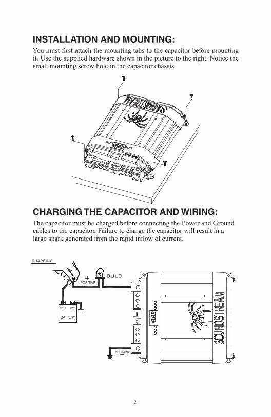
CHARGING THE CAPACITOR AND WIRING:The capacitor must be charged before connecting the Power and Ground cables to the capacitor. Failure to charge the capacitor will result in a large spark generated from the rapid inflow of current.
DISCHARGING THE CAPACITOR:
To Charge the capacitor: 1.
2.
3.
4.
When you want to take out the capacitor after you finish the installation process from original car audio system. You must do discharge process when you want to move the capacitor. It will be safe to release the power of the capacitor.
3
Make Capacitor positive terminal connections with amplifier and tighten the bolt. Do not over-tighten the bolts!
Connect the ground cable with battery, amplifier, then refer to the attached drawing.
Place the supplied charging bulb between positive terminal of the capacitor and the battery's positive terminal. Do this for 2 ~ 3 minutes or until the charging bulb goes out.
Immediately take out the charging bulb from the connecting wire after the charging process. And connect the positive cable of the battery directly to the positive terminal on the capacitor.
Caution: Stripped terminals are not covered under the capacitor's warranty.
Caution: The charging bulb will get hot!
INSTALLATION AND MOUNTING:
2
You must first attach the mounting tabs to the capacitor before mounting it. Use the supplied hardware shown in the picture to the right. Notice the small mounting screw hole in the capacitor chassis.
CHARGING THE CAPACITOR AND WIRING:The capacitor must be charged before connecting the Power and Ground cables to the capacitor. Failure to charge the capacitor will result in a large spark generated from the rapid inflow of current.
DISCHARGING THE CAPACITOR:
To Charge the capacitor: 1.
2.
3.
4.
When you want to take out the capacitor after you finish the installation process from original car audio system. You must do discharge process when you want to move the capacitor. It will be safe to release the power of the capacitor.
3
Make Capacitor positive terminal connections with amplifier and tighten the bolt. Do not over-tighten the bolts!
Connect the ground cable with battery, amplifier, then refer to the attached drawing.
Place the supplied charging bulb between positive terminal of the capacitor and the battery's positive terminal. Do this for 2 ~ 3 minutes or until the charging bulb goes out.
Immediately take out the charging bulb from the connecting wire after the charging process. And connect the positive cable of the battery directly to the positive terminal on the capacitor.
Caution: Stripped terminals are not covered under the capacitor's warranty.
Caution: The charging bulb will get hot!

4 digits hi-end blue light display DC voltage meter that can measure 0.1 DCV range.Reverse pole connecting PCB buzz warning function. If the capacitor is connected incorrectly by reversing the positive and negative wires during the installation process the PCB will issue a 45 second noise to warn you. Hi-end platinum plated 100% brass solid parts and chrome plated metal coverOver voltage limit and low battery voltage limit warning. When the system voltage peeks over 17 DCV or LESS than 10 DCV. The buzzer on the PCB will issue an audible noise warning. Multiple small capacitance capacitors linked to provide the lowest inner E.S.R. and largest moment discharge power.
Multiple Capacitor Wiring Diagram:
4
To Discharge the capacitor: With battery power disconnected, place the light bulb or resistor across the capacitor's positive and negative terminals until light goes out or for three minutes if using a resistor.
THIS POWER CAPACITOR MAY EXPLODE AND CAUSE SERIOUS INJURY IF ABUSED OR CONNECTED IMPROPERLY. PLEASE REFER TO THE INSTRUCTIONS CONTAINED IN THIS MANUAL FOR CORRECT OUNTING, CHARGING/DISCHARGING AND WIRING CONNECTION FOR THIS CAPAPCITOR PRIOR TO INSTALLATION.
One Year Warranty from the date of purchase.
WARNING!!
LIMITED WARRANTY
SPECIFICATIONS
DETAILED FEATURES:
Model: SC20C 20 Farad Hybrid Super Capacitor (Carbon And Electronic Capacitor) With Blue Digital Voltage Display, Blue Flash LED
Model: SC40C 40 Farad Hybrid Super Capacitor (Carbon And Electronic Capacitor) With Blue Digital Voltage Display, Blue Flash LED
Capacitance ............................................ 20,000,000 micro farad Working Voltage ........................................... 16DCSurge Voltage ................................................ 18DCE.S.R. (Equivalent Series Resistance)------ 0.0015 ohm @120hz/ 25 °CCapacitance Tolerance--------------------------- ± 10%
Capacitance ............................................ 40,000,000 micro farad Working Voltage ........................................... 16DCSurge Voltage ................................................ 18DCE. S. R. (Equivalent Series Resistance)........... 0.0015 ohm @120hz/25 °CCapacitance Tolerance.................................... ± 10%
a)
b)
c)
d)
e)
1
REMOTE
REMOTE
HEAD UNIT
REMOTE INPUT
REMOTE OUTPUT