tnb09 wrtrm OFC&OBC EZ:tnb09 wrtrm OFC&OBC Ty-Duct Wiring Duct.pdf · Technical...
26
In This Section… and Accessories and Accessories Ty-Duct ® and Accessories Overview.....................................E-2–E-4 How to Order Ty-Duct ® ................................................................E-5 Solid Wall Wiring Duct ..........................................................E-6–E-7 Wide Slot Wiring Duct ..........................................................E-8–E-9 Narrow Slot Wiring Duct ...................................................E-10–E-11 Round Hole Wiring Duct ...................................................E-12–E-13 Wide Slot Wiring Duct — Halogen-Free ...........................E-14–E-15 Accessories .....................................................................E-16–E-17 Tools ................................................................................E-18–E-19 Wiring Duct — Wire Fill Capacity ..............................................E-20 Specifications — Properties of Materials Used in Wiring Duct ...E-21 Technical Info. — Wiring Ducts ........................................E-22–E-25 Technical Information ................................................................E-26 www.tnb.com United States Tel: 901.252.8000 800.816.7809 Fax: 901.252.1354 Technical Services Tel: 888.862.3289
Transcript of tnb09 wrtrm OFC&OBC EZ:tnb09 wrtrm OFC&OBC Ty-Duct Wiring Duct.pdf · Technical...

z
In This Section…
and Accessories
and Accessories
Ty-Duct® and Accessories Overview.....................................E-2–E-4
How to Order Ty-Duct® ................................................................E-5
Solid Wall Wiring Duct ..........................................................E-6–E-7
Wide Slot Wiring Duct ..........................................................E-8–E-9
Narrow Slot Wiring Duct...................................................E-10–E-11
Round Hole Wiring Duct ...................................................E-12–E-13
Wide Slot Wiring Duct — Halogen-Free ...........................E-14–E-15
Accessories .....................................................................E-16–E-17
Tools ................................................................................E-18–E-19
Wiring Duct — Wire Fill Capacity ..............................................E-20
Specifications — Properties of Materials Used in Wiring Duct ...E-21
Technical Info. — Wiring Ducts........................................E-22–E-25
Technical Information ................................................................E-26
www.tnb.com
United StatesTel: 901.252.8000
800.816.7809Fax: 901.252.1354
Technical ServicesTel: 888.862.3289

Overview
Thomas & Betts’ innovative new Ty-Duct products offer a totalsolution for routing and concealing wiring in control panels. Many different sizes are available to accommodate anything fromthe smallest wallmount panel to the larger integrated systems!
Here are some of the impressive features incorporated into ourwiring duct solutions.
Ty-Duct Features
Ty-Duct® — The versatileconfigurations you need for routingand concealing wiring!
Available in 4 Colors
Gray White Black IntrinsicBlue
and
Acce
ssor
ies
Ty-Duct Certifications
• UL Recognized Continuous-Use Temperature — 122˚ F (50˚ C)
• UL 94 Flammability — Rating of V-0
• Conforms with NFPA 79-2002 Section 14.3.1Requirement for Flame Retardant Material
• CE compliant for European shipping
• CSA Certified
• RoHS Certified
• Available in Solid, Wide Slot, Narrow Slot, and RoundHole versions to meet yourcapacity and flexibility needs
• Widths from .75" to 6" and depths from 1" to 5"
• Optional adhesive back for quick, hassle-freeinstallation
• Complete selection ofaccessories and tools for installation
• Lead-free construction
• Lightweight Halogen-freeavailable for Wide SlotWiring Duct
E-2
United StatesTel: 901.252.8000
800.816.7809Fax: 901.252.1354
Technical ServicesTel: 888.862.3289
www.tnb.com

Overview
and Accessories
Ty-Duct® Advantages
• Two-point contact design enables the cover to be easily installed in the right place with less force
• Co-extruded cover ensures the cover will stay in place and will not slip once installed
• Smooth corners and edges will not damage or disfigure wires
• Flush cover design enables greater capacityand sits flush with duct side wall
• Triple restricted slots speed installation while enabling better wire retaining in duct
• Dual score lines — Upper score line allowsfingers to be broken out without tools and thelower score line allows side wall sections to be removed easily
• V-shaped slot lead-in funnels wires into slot for easier wire insertion
• Staggered mounting hole pattern (larger widths)
• Universal Mounting Clip secures into the baseto perform several tasks:
– Enables divider to be snapped into base
– Slots in the Universal Mounting Clip allowcable ties to pass through to hold wire bundles in place
– 2 slot sizes on Universal Mounting Clipaccommodate traditional nylon cable ties or hook and loop fasteners
• Slotted and Solid Divider accommodatesvarious wiring applications
• Grooved cover provides better grip for removal and placement of cover onto base
• Writable protective film on covers protects from work site scratches and scuffs and enables temporary marking or labeling
• Embossed holes enable Universal MountingClips to be installed, even after the duct has been riveted to the panel
• PVC construction is excellent for flame retardancy
• North American and DIN standard mounting holes
Two-PointContact Design
Flush CoverDesign
Co-ExtrudedCover
GroovedCover
Dual Score Lines
UniversalMounting Clip
EmbossedHoles
V-Shaped SlotLead-Ins
WritableProtective Film
Solid Divider
Triple RestrictedSlots
Smooth Corners& Edges
E-3
United StatesTel: 901.252.8000
800.816.7809Fax: 901.252.1354
Technical ServicesTel: 888.862.3289
www.tnb.com

and
Acce
ssor
ies
Overview
Solid Wall Wiring Duct
• Engineered to restrict wire access for greater security
• Available in improved flush sidewall and cover style for greater wire capacity
Wide Slot Wiring Duct
• Wide fingers and slots increase rigidity and enable insertion of bundles
• Halogen-free version available
NEW Solid Wall DuctApplication Photo to
be Inserted Here!
Narrow Slot Wiring Duct
• Smaller, higher number of fingers for more concise harnessing
• Finger design restricts wire from slipping along the edge — creates two or three levels of wire service
Round Hole Wiring Duct
• Multiple rows of holes retain wire at different heights and positions with or without the cover
• Features maximum number of wire holes
E-4
United StatesTel: 901.252.8000
800.816.7809Fax: 901.252.1354
Technical ServicesTel: 888.862.3289
www.tnb.com

and Accessories
How to Order Ty-Duct ®
SIZE (W x H) COVER DUCT STD. COVER STD. LENGTH CAT. NO. DESCRIPTION IN. MM CAT. NO. CTN. QTY. CTN. QTY. (FT.)
TY75X1WP[ G ]6NM .75 x 1 Wide Slot Duct 0.94 x 1.09 23.9 x 27.7 120TY75X15WP[B ]6A .75 x 1.5 Wide Slot Duct 0.94 x 1.56 23.9 x 39.6 TY75CP[ _ ]6 120 120 6TY75X2WP[ I ]6 .75 x 2 Wide Slot Duct 0.94 x 2.07 23.9 x 52.6 120
[ _ ] = space for color identifier:
G = Gray
W = White
B = Black
I = Intrinsic Blue
Catalog Number must be completed by adding suffix G for Gray, W for White, I for Intrinsic Blue, B for Black.Example: TY75x2WPI6 is a .75" x 2" wide slot intrinsic blue duct. Cover color must be specified also.
To order duct without mounting holes, add suffix NM to catalog number. Example: TY75X1WPG6NM is a .75" x 1" wide slot gray duct with no mounting holes.
To order Adhesive-BackedDuct, add suffix A to CatalogNumber.
Example: TY75x15WPB6Ais a .75" x 1.5" wide slotblack duct with adhesivebacking.
Shelf life for adhesive is 1 year.
Nominal Width x Nominal Height Standard Carton Quantity
SP = SolidWP = Wide SlotNP = Narrow SlotRP = Round Hole
Standard lengths are 6 feet.
After selecting the appropriate Ty-Duct solutions for your application, make sure you complete the following checklist.
Specify color
Indicate if you want the duct without mounting holes
Indicate if you want anadhesive-backed duct (not available in Wide Slot Duct — Halogen Free)
Ordering the Ty-Duct® products you need is as easy as 1, 2, 3!
1
1
2
2
3
3
Catalog Number must be completed by adding suffix SP for Solid or WP for Wide Slot. Example: TY2DSPG6 is a 2" high solid wall gray divider.
Catalog Number must be completed by adding suffix G for Gray, W for White, I forIntrinsic Blue, B for Black. Example: TY2DSPG6 is a 2" high solid wall gray divider.
Catalog Number must be completed by adding suffix G for Gray, W for White, I forIntrinsic Blue, B for Black. Example: TYCSG6 is a gray corner strip.
For Ty-Duct Wiring Duct and Covers:
For Ty-Duct Dividers: For Ty-Duct Corner& Joining Strips:
LENGTH STD.CAT. NO. DESCRIPTION (FT.) CTN. QTY
TY2D[ SP ][ G ]6 2" High Wall Divider 6 120
LENGTH STD.CAT. NO. DESCRIPTION (FT.) CTN. QTY
TYCS[ G ]6 Corner Strip 6 120
TYJS[ G ]6 Joining Strip 6 120
Corner Strip sample shown below. Joining Strips are ordered thesame way.
E-5
United StatesTel: 901.252.8000
800.816.7809Fax: 901.252.1354
Technical ServicesTel: 888.862.3289
www.tnb.com

Solid Wall Wiring Duct
Solid Wall Duct — PVC• Engineered to restrict wire access
• Constructed of flame-retardant PVC
• Improved flush sidewall and cover style for greater wire capacity
• Versatile North American and DIN Standard mounting holes enable same duct for multiple applications
• Base score line
• Lead-free construction
• Integrated mounting holes (see page E-22 for illustration)
Fire-retardant PVC offers the protection you need!
and
Acce
ssor
ies
Two-PointContact Design
Flush CoverDesign
Base ScoreLine
EmbossedHoles
UniversalMounting Clip
(see page E-16)
Divider Wall(see page E-16)
GroovedCover
E-6
United StatesTel: 901.252.8000
800.816.7809Fax: 901.252.1354
Technical ServicesTel: 888.862.3289
www.tnb.com

Solid Wall Duct
SIZE (W x H) COVER DUCT STD. COVER STD. LENGTH CAT. NO. DESCRIPTION IN. MM CAT. NO. CTN. QTY. CTN. QTY. (FT.)
TY75X1SP[ _ ]6 .75 x 1 Solid Wall Duct 0.94 x 1.24 23.9 x 31.5 120TY75X15SP[ _ ]6 .75 x 1.5 Solid Wall Duct 0.94 x 1.70 23.9 x 43.2 TY75CP[ _ ]6 120 120 6TY75X2SP[ _ ]6 .75 x 2 Solid Wall Duct 0.94 x 2.19 23.9 x 55.6 120TY1X1SP[ _ ]6 1 x 1 Solid Wall Duct 1.25 x 1.24 31.8 x 31.5 120TY1X15SP[ _ ]6 1 x 1.5 Solid Wall Duct 1.25 x 1.70 31.8 x 43.2 120TY1X2SP[ _ ]6 1 x 2 Solid Wall Duct 1.25 x 2.19 31.8 x 55.6 TY1CP[ _ ]6 120 120 6TY1X3SP[ _ ]6 1 x 3 Solid Wall Duct 1.25 x 3.14 31.8 x 79.8 120TY1X4SP[ _ ]6 1 x 4 Solid Wall Duct 1.25 x 4.46 31.8 x 113.3 60TY15X1SP[ _ ]6 1.5 x 1 Solid Wall Duct 1.75 x 1.24 44.5 x 31.5 120TY15X15SP[ _ ]6 1.5 x 1.5 Solid Wall Duct 1.75 x 1.70 44.5 x 43.2 120TY15X2SP[ _ ]6 1.5 x 2 Solid Wall Duct 1.75 x 2.19 44.5 x 55.6 TY15CP[ _ ]6 120 120 6TY15X3SP[ _ ]6 1.5 x 3 Solid Wall Duct 1.75 x 3.14 44.5 x 79.8 120TY15X4SP[ _ ]6 1.5 x 4 Solid Wall Duct 1.75 x 4.46 44.5 x 113.3 60TY2X1SP[ _ ]6 2 x 1 Solid Wall Duct 2.25 x 1.24 57.2 x 31.5 120TY2X15SP[ _ ]6 2 x 1.5 Solid Wall Duct 2.25 x 1.70 57.2 x 43.2 120TY2X2SP[ _ ]6 2 x 2 Solid Wall Duct 2.25 x 2.19 57.2 x 55.6 TY2CP[ _ ]6 120 120 6TY2X3SP[ _ ]6 2 x 3 Solid Wall Duct 2.25 x 3.14 57.2 x 79.8 60TY2X4SP[ _ ]6 2 x 4 Solid Wall Duct 2.25 x 4.46 57.2 x 113.3 60TY2X5SP[ _ ]6 2 x 5 Solid Wall Duct 2.25 x 5.15 57.2 x 130.8 60TY25X2SP[ _ ]6 2.5 x 2 Solid Wall Duct 2.75 x 2.19 69.9 x 55.6 120TY25X3SP[ _ ]6 2.5 x 3 Solid Wall Duct 2.75 x 3.14 69.9 x 79.8 TY25CP[ _ ]6 60 120 6TY25X4SP[ _ ]6 2.5 x 4 Solid Wall Duct 2.75 x 4.46 69.9 x 113.3 60TY3X1SP[ _ ]6 3 x 1 Solid Wall Duct 3.25 x 1.24 82.6 x 31.5 120TY3X2SP[ _ ]6 3 x 2 Solid Wall Duct 3.25 x 2.19 82.6 x 55.6 60TY3X3SP[ _ ]6 3 x 3 Solid Wall Duct 3.25 x 3.14 82.6 x 79.8 TY3CP[ _ ]6 60 120 6TY3X4SP[ _ ]6 3 x 4 Solid Wall Duct 3.25 x 4.46 82.6 x 113.3 60TY3X5SP[ _ ]6 3 x 5 Solid Wall Duct 3.25 x 5.15 82.6 x 130.8 60TY4X15SP[ _ ]6 4 x 1.5 Solid Wall Duct 4.25 x 1.70 108.0 x 43.2 60TY4X2SP[ _ ]6 4 x 2 Solid Wall Duct 4.25 x 2.19 108.0 x 55.6 60TY4X3SP[ _ ]6 4 x 3 Solid Wall Duct 4.25 x 3.14 108.0 x 79.8 TY4CP[ _ ]6 60 120 6TY4X4SP[ _ ]6 4 x 4 Solid Wall Duct 4.25 x 4.46 108.0 x 113.3 30TY4X5SP[ _ ]6 4 x 5 Solid Wall Duct 4.25 x 5.15 108.0 x 130.8 30TY6X4SP[ _ ]6 6 x 4 Solid Wall Duct 6.25 x 4.46 158.8 x 113.3 TY6CP[ _ ]6 30 60 6
[ _ ] = space for color identifier:
G = Gray
W = White
B = Black
I = Intrinsic Blue
• Standard lengths are 6 feet.
+Catalog Number must be completed by adding suffix G for Gray, W for White, I for Intrinsic Blue, B for Black. Example: TY75X1SPG6 is a .75" x 1" solid wall gray duct.
To order duct without mounting holes, add suffix NM to catalog number. Example: TY75X1SPG6NM is a .75" x 1" solid wall gray duct with no mounting holes.
To order Adhesive-Backed Duct, add suffix A to Catalog Number. Example: TY75X1SPG6A is a .75" x 1" solid wall gray duct with adhesive backing. Shelf life for adhesive is 1 year.
PVC duct is UL Recognized , CSA Certified and CE Compliant.
Front View with Cover Side View without Cover
H
W
For a complete listing of Solid Walldimensional details, see page E-22.
and Accessories
E-7
United StatesTel: 901.252.8000
800.816.7809Fax: 901.252.1354
Technical ServicesTel: 888.862.3289
www.tnb.com

Wide Slot Wiring Duct
Wide Slot Wiring Duct — PVC• Wide fingers and slots increase rigidity
and enable insertion of bundles
• Non-slip cover does not slide easily and resists vibration
• Rounded edges keep hands and wires free of abrasion
• V-shaped slot lead-in enables easier and faster wire installation
• Dual score lines are designed to yield cleanbreakoffs at the base of the slot and the duct
• Restricted slot design makes sure that wires are held with or without the cover inserted
• Flush cover attaches flush with sidewall for finished look
• Improved flush sidewall and cover style for greater wire capacity
• Versatile North American and DIN Standard mounting holesenables same duct for multiple applications
• Constructed of flame-retardant PVC
• Integrated mounting holes — larger sizes include staggeredholes for mounting flexibility (see page E-23 for illustration)
• Lead-free construction
Greater sidewall rigidity with increased versatility!
and
Acce
ssor
ies
Two-PointContact Design
Flush CoverDesign
Dual ScoreLines
EmbossedHoles
Wide Fingers& Slots
V-ShapedSlot Lead-In
GroovedCover
E-8
United StatesTel: 901.252.8000
800.816.7809Fax: 901.252.1354
Technical ServicesTel: 888.862.3289
www.tnb.com

Wide Slot Wiring Duct
SIZE (W x H) COVER DUCT STD. COVER STD. LENGTH CAT. NO. DESCRIPTION IN. MM CAT. NO. CTN. QTY CTN. QTY (FT.)
TY75X1WP[ _ ]6 .75 x 1 Wide Slot Duct 0.94 x 1.24 23.9 x 31.5 120TY75X15WP[ _ ]6 .75 x 1.5 Wide Slot Duct 0.94 x 1.70 23.9 x 43.2 TY75CP[ _ ]6 120 120 6TY75X2WP[ _ ]6 .75 x 2 Wide Slot Duct 0.94 x 2.19 23.9 x 55.6 120TY1X1WP[ _ ]6 1 x 1 Wide Slot Duct 1.25 x 1.24 31.8 x 31.5 120TY1X15WP[ _ ]6 1 x 1.5 Wide Slot Duct 1.25 x 1.70 31.8 x 43.2 120TY1X2WP[ _ ]6 1 x 2 Wide Slot Duct 1.25 x 2.19 31.8 x 55.6 TY1CP[ _ ]6 120 120 6TY1X3WP[ _ ]6 1 x 3 Wide Slot Duct 1.25 x 3.14 31.8 x 79.8 120TY1X4WP[ _ ]6 1 x 4 Wide Slot Duct 1.25 x 4.46 31.8 x 113.3 60TY15X1WP[ _ ]6 1.5 x 1 Wide Slot Duct 1.75 x 1.24 44.5 x 31.5 120TY15X15WP[ _ ]6 1.5 x 1.5 Wide Slot Duct 1.75 x 1.70 44.5 x 43.2 120TY15X2WP[ _ ]6 1.5 x 2 Wide SlotDuct 1.75 x 2.19 44.5 x 55.6 TY15CP[ _ ]6 120 120 6TY15X3WP[ _ ]6 1.5 x 3 Wide Slot Duct 1.75 x 3.14 44.5 x 79.8 120TY15X4WP[ _ ]6 1.5 x 4 Wide Slot Duct 1.75 x 4.46 44.5 x 113.3 60TY2X1WP[ _ ]6 2 x 1 Wide Slot Duct 2.25 x 1.24 57.2 x 31.5 120TY2X15WP[ _ ]6 2 x 1.5 Wide Slot Duct 2.25 x 1.70 57.2 x 43.2 120TY2X2WP[ _ ]6 2 x 2 Wide Slot Duct 2.25 x 2.19 57.2 x 55.6 TY2CP[ _ ]6 120 120 6TY2X3WP[ _ ]6 2 x 3 Wide Slot Duct 2.25 x 3.14 57.2 x 79.8 60TY2X4WP[ _ ]6 2 x 4 Wide Slot Duct 2.25 x 4.46 57.2 x 113.3 60TY2X5WP[ _ ]6 2 x 5 Wide Slot Duct 2.25 x 5.15 57.2 x 130.8 60TY25X2WP[ _ ]6 2.5 x 2 Wide Slot Duct 2.75 x 2.19 69.9 x 55.6 120TY25X3WP[ _ ]6 2.5 x 3 Wide Slot Duct 2.75 x 3.14 69.9 x 79.8 TY25CP[ _ ]6 60 120 6TY25X4WP[ _ ]6 2.5 x 4 Wide Slot Duct 2.75 x 4.46 69.9 x 113.3 60TY3X1WP[ _ ]6 3 x 1 Wide SlotDuct 3.25 x 1.24 82.6 x 31.5 120TY3X2WP[ _ ]6 3 x 2 Wide Slot Duct 3.25 x 2.19 82.6 x 55.6 60TY3X3WP[ _ ]6 3 x 3 Wide Slot Duct 3.25 x 3.14 82.6 x 79.8 TY3CP[ _ ]6 60 120 6TY3X4WP[ _ ]6 3 x 4 Wide Slot Duct 3.25 x 4.46 82.6 x 113.3 60TY3X5WP[ _ ]6 3 x 5 Wide Slot Duct 3.25 x 5.15 82.6 x 130.8 60TY4X15WP[ _ ]6 4 x 1.5 Wide Slot Duct 4.25 x 1.70 108.0 x 43.2 60TY4X2WP[ _ ]6 4 x 2 Wide Slot Duct 4.25 x 2.19 108.0 x 55.6 60TY4X3WP[ _ ]6 4 x 3 Wide Slot Duct 4.25 x 3.14 108.0 x 79.8 TY4CP[ _ ]6 60 120 6TY4X4WP[ _ ]6 4 x 4 Wide Slot Duct 4.25 x 4.46 108.0 x 113.3 30TY4X5WP[ _ ]6 4 x 5 Wide Slot Duct 4.25 x 5.15 108.0 x 130.8 30TY6X4WP[ _ ]6 6 x 4 Wide Slot Duct 6.25 x 4.46 158.8 x 113.3 TY6CP[ _ ]6 30 60 6
[ _ ] = space for color identifier:
G = Gray
W = White
B = Black
I = Intrinsic Blue
• Standard lengths are 6 feet.
+Catalog Number must be completed by adding suffix G for Gray, W for White, I for Intrinsic Blue, B for Black. Example: TY75X1WPG6 is a .75" x 1" wide slot gray duct.
To order duct without mounting holes, add suffix NM to catalog number. Example: TY75X1WPG6NM is a .75" x 1" wide slot gray duct with no mounting holes.
To order Adhesive-Backed Duct, add suffix A to Catalog Number. Example: TY75X1WPG6A is a .75" x 1" wide slot gray duct with adhesive backing. Shelf life for adhesive is 1 year.
PVC duct is UL Recognized , CSA Certified and CE Compliant.
Front View with Cover Side View without Cover
H
W
For a complete listing of Wide Slotdimensional details see page E-23.
and Accessories
E-9
United StatesTel: 901.252.8000
800.816.7809Fax: 901.252.1354
Technical ServicesTel: 888.862.3289
www.tnb.com

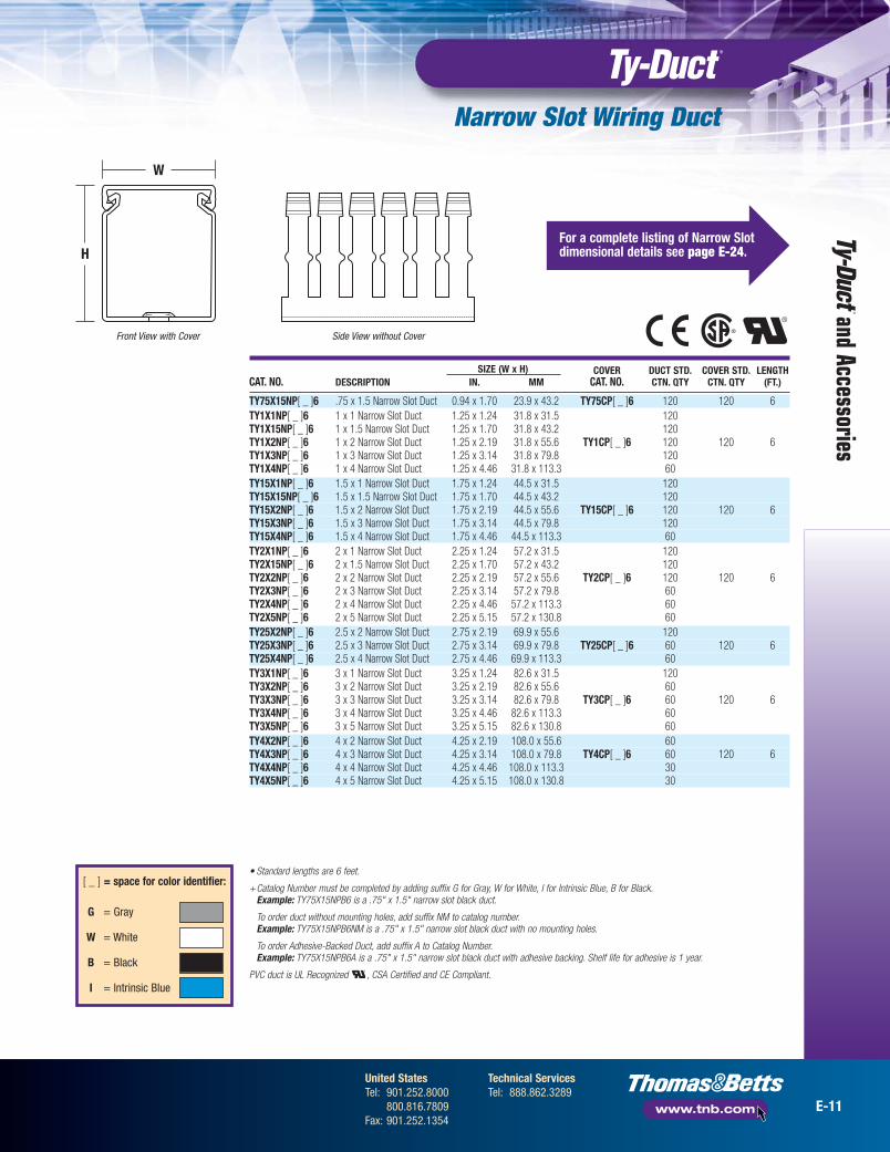
Narrow Slot Wiring Duct
Narrow Slot Wiring Duct• Smaller, higher number of fingers
for more concise harnessing
• Non-slip cover does not slide easily and resists vibration
• Rounded edges keep hands and wires free of abrasion
• V-shaped slot lead-in enables easier and faster wire installation
• Restricted slot design makes sure that wires are held with or without the cover inserted
• Flush cover attaches flush with sidewall for finished look
• Versatile North American and DIN Standard mountingholes enable same duct for multiple applications
• Dual score lines are designed to yield clean breakoffs at the base of the slot and the duct
• Finger design restricts wire from slippingalong the edge; creates two or three levelsof wire service (see page E-24 forillustration)
• Lead-free construction
• Constructed of flame-retardant PVC
• Integrated mounting holes (see page E-24for example)
Designed to fit the spacing ofhigh-density terminal blocks!
and
Acce
ssor
ies
EmbossedHoles
V-ShapedSlot Lead-In
GroovedCover Restricted Slot
Design
Three Levels of Wire Service
Two Levels of Wire Service
Narrow Fingers& Slots
Two-PointContact Design
Flush CoverDesign
Dual ScoreLines
E-10
United StatesTel: 901.252.8000
800.816.7809Fax: 901.252.1354
Technical ServicesTel: 888.862.3289
www.tnb.com
Narrow Slot Wiring Duct
SIZE (W x H) COVER DUCT STD. COVER STD. LENGTH CAT. NO. DESCRIPTION IN. MM CAT. NO. CTN. QTY CTN. QTY (FT.)
TY75X15NP[ _ ]6 .75 x 1.5 Narrow Slot Duct 0.94 x 1.70 23.9 x 43.2 TY75CP[ _ ]6 120 120 6TY1X1NP[ _ ]6 1 x 1 Narrow Slot Duct 1.25 x 1.24 31.8 x 31.5 120TY1X15NP[ _ ]6 1 x 1.5 Narrow Slot Duct 1.25 x 1.70 31.8 x 43.2 120TY1X2NP[ _ ]6 1 x 2 Narrow Slot Duct 1.25 x 2.19 31.8 x 55.6 TY1CP[ _ ]6 120 120 6TY1X3NP[ _ ]6 1 x 3 Narrow Slot Duct 1.25 x 3.14 31.8 x 79.8 120TY1X4NP[ _ ]6 1 x 4 Narrow Slot Duct 1.25 x 4.46 31.8 x 113.3 60TY15X1NP[ _ ]6 1.5 x 1 Narrow Slot Duct 1.75 x 1.24 44.5 x 31.5 120TY15X15NP[ _ ]6 1.5 x 1.5 Narrow Slot Duct 1.75 x 1.70 44.5 x 43.2 120TY15X2NP[ _ ]6 1.5 x 2 Narrow Slot Duct 1.75 x 2.19 44.5 x 55.6 TY15CP[ _ ]6 120 120 6TY15X3NP[ _ ]6 1.5 x 3 Narrow Slot Duct 1.75 x 3.14 44.5 x 79.8 120TY15X4NP[ _ ]6 1.5 x 4 Narrow Slot Duct 1.75 x 4.46 44.5 x 113.3 60TY2X1NP[ _ ]6 2 x 1 Narrow Slot Duct 2.25 x 1.24 57.2 x 31.5 120TY2X15NP[ _ ]6 2 x 1.5 Narrow Slot Duct 2.25 x 1.70 57.2 x 43.2 120TY2X2NP[ _ ]6 2 x 2 Narrow Slot Duct 2.25 x 2.19 57.2 x 55.6 TY2CP[ _ ]6 120 120 6TY2X3NP[ _ ]6 2 x 3 Narrow Slot Duct 2.25 x 3.14 57.2 x 79.8 60TY2X4NP[ _ ]6 2 x 4 Narrow Slot Duct 2.25 x 4.46 57.2 x 113.3 60TY2X5NP[ _ ]6 2 x 5 Narrow Slot Duct 2.25 x 5.15 57.2 x 130.8 60TY25X2NP[ _ ]6 2.5 x 2 Narrow Slot Duct 2.75 x 2.19 69.9 x 55.6 120TY25X3NP[ _ ]6 2.5 x 3 Narrow Slot Duct 2.75 x 3.14 69.9 x 79.8 TY25CP[ _ ]6 60 120 6TY25X4NP[ _ ]6 2.5 x 4 Narrow Slot Duct 2.75 x 4.46 69.9 x 113.3 60TY3X1NP[ _ ]6 3 x 1 Narrow Slot Duct 3.25 x 1.24 82.6 x 31.5 120TY3X2NP[ _ ]6 3 x 2 Narrow Slot Duct 3.25 x 2.19 82.6 x 55.6 60TY3X3NP[ _ ]6 3 x 3 Narrow Slot Duct 3.25 x 3.14 82.6 x 79.8 TY3CP[ _ ]6 60 120 6TY3X4NP[ _ ]6 3 x 4 Narrow Slot Duct 3.25 x 4.46 82.6 x 113.3 60TY3X5NP[ _ ]6 3 x 5 Narrow Slot Duct 3.25 x 5.15 82.6 x 130.8 60TY4X2NP[ _ ]6 4 x 2 Narrow Slot Duct 4.25 x 2.19 108.0 x 55.6 60TY4X3NP[ _ ]6 4 x 3 Narrow Slot Duct 4.25 x 3.14 108.0 x 79.8 TY4CP[ _ ]6 60 120 6TY4X4NP[ _ ]6 4 x 4 Narrow Slot Duct 4.25 x 4.46 108.0 x 113.3 30TY4X5NP[ _ ]6 4 x 5 Narrow Slot Duct 4.25 x 5.15 108.0 x 130.8 30
[ _ ] = space for color identifier:
G = Gray
W = White
B = Black
I = Intrinsic Blue
• Standard lengths are 6 feet.
+Catalog Number must be completed by adding suffix G for Gray, W for White, I for Intrinsic Blue, B for Black. Example: TY75X15NPB6 is a .75" x 1.5" narrow slot black duct.
To order duct without mounting holes, add suffix NM to catalog number. Example: TY75X15NPB6NM is a .75" x 1.5" narrow slot black duct with no mounting holes.
To order Adhesive-Backed Duct, add suffix A to Catalog Number. Example: TY75X15NPB6A is a .75" x 1.5" narrow slot black duct with adhesive backing. Shelf life for adhesive is 1 year.
PVC duct is UL Recognized , CSA Certified and CE Compliant.
Front View with Cover Side View without Cover
H
W
For a complete listing of Narrow Slotdimensional details see page E-24.
and Accessories
E-11
United StatesTel: 901.252.8000
800.816.7809Fax: 901.252.1354
Technical ServicesTel: 888.862.3289
www.tnb.com

Round Hole Wiring Duct
SIZE (W x H) COVER DUCT STD. COVER STD. LENGTH CAT. NO. DESCRIPTION IN. MM CAT. NO. CTN. QTY CTN. QTY (FT.)
TY1X15RP[ _ ]6 1 x 1.5 Round Hole Duct 1.75 x 1.70 44.5 x 43.2 120TY1X2RP[ _ ]6 1 x 2 Round Hole Duct 1.25 x 2.19 31.8 x 55.6 TY1CP[ _ ]6 120 120 6TY1X3RP[ _ ]6 1 x 3 Round Hole Duct 1.25 x 3.14 31.8 x 79.8 120TY1X4RP[ _ ]6 1 x 4 Round Hole Duct 1.25 x 4.46 31.8 x 113.3 60TY15X15RP[ _ ]6 1.5 x 1.5 Round Hole Duct 1.75 x 1.70 44.5 x 43.2 120TY15X2RP[ _ ]6 1.5 x 2 Round Hole Duct 1.75 x 2.19 44.5 x 55.6 TY15CP[ _ ]6 120 120 6TY15X3RP[ _ ]6 1.5 x 3 Round Hole Duct 1.75 x 3.14 44.5 x 79.8 120TY15X4RP[ _ ]6 1.5 x 4 Round Hole Duct 1.75 x 4.46 44.5 x 113.3 60TY2X15RP[ _ ]6 2 x 1.5 Round Hole Duct 2.25 x 1.70 57.2 x 43.2 120TY2X2RP[ _ ]6 2 x 2 Round Hole Duct 2.25 x 2.19 57.2 x 55.6 TY2CP[ _ ]6 120 120 6TY2X3RP[ _ ]6 2 x 3 Round Hole Duct 2.25 x 3.14 57.2 x 79.8 60TY2X4RP[ _ ]6 2 x 4 Round Hole Duct 2.25 x 4.46 57.2 x 113.3 60TY3X2RP[ _ ]6 3 x 2 Round Hole Duct 3.25 x 2.19 82.6 x 55.6 60TY3X3RP[ _ ]6 3 x 3 Round Hole Duct 3.25 x 3.14 82.6 x 79.8 TY3CP[ _ ]6 60 120 6TY3X4RP[ _ ]6 3 x 4 Round Hole Duct 3.25 x 4.46 82.6 x 113.3 60TY4X15RP[ _ ]6 4 x 1.5 Round Hole Duct 4.25 x 1.70 108.0 x 43.2 60TY4X2RP[ _ ]6 4 x 2 Round Hole Duct 4.25 x 2.19 108.0 x 55.6 TY4CP[ _ ]6 60 120 6TY4X3RP[ _ ]6 4 x 3 Round Hole Duct 4.25 x 3.14 108.0 x 79.8 60TY4X4RP[ _ ]6 4 x 4 Round Hole Duct 4.25 x 4.46 108.0 x 113.3 30
[ _ ] = space for color identifier:
G = Gray
W = White
B = Black
I = Intrinsic Blue
• Standard lengths are 6 feet.
+Catalog Number must be completed by adding suffix G for Gray, W for White, I for Intrinsic Blue, B for Black. Example: TY1X15RPG6 is a 1" x 1.5" round hole gray duct.
To order duct without mounting holes, add suffix NM to catalog number. Example: TY1X15RPG6NM is a 1" x 1.5" round hole gray duct with no mounting holes.
To order Adhesive-Backed Duct, add suffix A to Catalog Number.Example: TY1X15RPG6A is a 1" x 1.5" round hole gray duct with adhesive backing.
PVC duct is UL Recognized , CSA Certified and CE Compliant.
Front View with Cover Side View without Cover
H
W
For a complete listing of Round Holedimensional details see page E-25.
and Accessories
E-13
United StatesTel: 901.252.8000
800.816.7809Fax: 901.252.1354
Technical ServicesTel: 888.862.3289
www.tnb.com

Round Hole Wiring Duct
Round Hole Wiring Duct• Multiple rows of holes retain wire at different
heights and positions with or without the cover
• Features maximum number of wire holes
• Greater wall rigidity than open slot duct
• Non-slip cover does not slide easily and resists vibration
• Rounded edges keep hands and wires free of abrasion
• Base score line enables sidewall section to be removed
• Cover attaches flush with sidewall for finished look
• Constructed of flame-retardant PVC
• Integrated mounting holes — larger sizesinclude staggered holes for mountingflexibility (see page E-25 for illustration)
• Lead-free construction
Holes retain and support wires at different heights!
and
Acce
ssor
ies
EmbossedHoles
GroovedCover
RoundHoles
Two-PointContact Design
Base Score Line
Flush CoverDesign
E-12
United StatesTel: 901.252.8000
800.816.7809Fax: 901.252.1354
Technical ServicesTel: 888.862.3289
www.tnb.com

Wide Slot Wiring Duct — Halogen-Free
Wide Slot Wiring Duct —Halogen-Free• Halogen-free construction
• Higher temperature rating than PVC
• Wide fingers and slots increase rigidity and enable for insertion of bundles
• Non-slip cover does not slide easily and resists vibration
• Rounded edges keep hands and wires free of abrasion
• Dual score lines are designed to yield clean breakoffs at the base of the slot and the duct
• V-shaped slot lead-in enables easier and faster wire installation
Perfect for high-temperature areas!
and
Acce
ssor
ies
EmbossedHoles
Wide Fingers& Slots
V-ShapedSlot Lead-In
GroovedCover
Two-PointContact Design
Flush CoverDesign
Dual Score Lines
• Integrated mounting holes — larger sizesinclude staggered holes for mounting flexibility(see page E-23 for illustration)
• Restricted slot design makes sure that wires are held with or without the cover inserted
• Available only in white
E-14
United StatesTel: 901.252.8000
800.816.7809Fax: 901.252.1354
Technical ServicesTel: 888.862.3289
www.tnb.com

Wiring Duct Solid DividerWall — Halogen-Free
Wide Slot Wiring Duct — Halogen-Free
SIZE (W x H) COVER DUCT STD. COVER STD. LENGTH CAT. NO. DESCRIPTION IN. MM CAT. NO. CTN. QTY CTN. QTY (FT.)
TY1X1WHW6 1 x 1 Halogen-Free White Duct 1.25 x 1.24 31.8 x 31.5 120TY1X15WHW6 1 x 1.5 Halogen-Free White Duct 1.25 x 1.70 31.8 x 43.2 120TY1X2WHW6 1 x 2 Halogen-Free White Duct 1.25 x 2.19 31.8 x 55.6 TY1CHW6 120 120 6TY1X3WHW6 1 x 3 Halogen-Free White Duct 1.25 x 3.14 31.8 x 79.8 120TY1X4WHW6 1 x 4 Halogen-Free White Duct 1.25 x 4.46 31.8 x 113.3 60TY15X15WHW6 1.5 x 1.5 Halogen-Free White Duct 1.75 x 1.70 44.5 x 43.2 120TY15X2WHW6 1.5 x 2 Halogen-Free White Duct 1.75 x 2.19 44.5 x 55.6 TY15CHW6 120 120 6TY15X3WHW6 1.5 x 3 Halogen-Free White Duct 1.75 x 3.14 44.5 x 79.8 120TY15X4WHW6 1.5 x 4 Halogen-Free White Duct 1.75 x 4.46 44.5 x 113.3 60TY2X1WHW6 2 x 1 Halogen-Free White Duct 2.25 x 1.24 57.2 x 31.5 120TY2X2WHW6 2 x 2 Halogen-Free White Duct 2.25 x 2.19 57.2 x 55.6 TY2CHW6 120 120 6TY2X3WHW6 2 x 3 Halogen-Free White Duct 2.25 x 3.14 57.2 x 79.8 60TY2X4WHW6 2 x 4 Halogen-Free White Duct 2.25 x 4.46 57.2 x 113.3 60TY3X1WHW6 3 x 1 Halogen-Free White Duct 3.25 x 1.24 82.6 x 31.5 120TY3X2WHW6 3 x 2 Halogen-Free White Duct 3.25 x 2.19 82.6 x 55.6 60TY3X3WHW6 3 x 3 Halogen-Free White Duct 3.25 x 3.14 82.6 x 79.8 TY3CHW6 60 120 6TY3X4WHW6 3 x 4 Halogen-Free White Duct 3.25 x 4.46 82.6 x 113.3 60TY3X5WHW6 3 x 5 Halogen-Free White Duct 3.25 x 5.15 82.6 x 130.8 60TY4X2WHW6 4 x 2 Halogen-Free White Duct 4.25 x 2.19 108.0 x 55.6 60TY4X3WHW6 4 x 3 Halogen-Free White Duct 4.25 x 3.14 108.0 x 79.8 TY4CHW6 60 120 6TY4X4WHW6 4 x 4 Halogen-Free White Duct 4.25 x 4.46 108.0 x 113.3 30TY4X5WHW6 4 x 5 Halogen-Free White Duct 4.25 x 5.15 108.0 x 130.8 30
• Standard lengths are 6 feet.
To order duct without mounting holes, add suffix NM to catalog number. Example: TY1XWHW6NM is a 1" x 1" wide slot halogen-free white duct with no mounting holes.
Halogen-free (modified PPE) duct is UL Recognized , CSA Certified and meets the JIC requirements.
Front View with Cover Side View without Cover
H
W
For a complete listing of Wide Slotdimensional details see page E-23.
and Accessories
W = White
FITS DUCT STD. CTN.CAT. NO. TRADE SIZE QTY. LENGTH FT.
TY1DSHW6 1" H 120 6TY1.5DSHW6 11⁄2" H 120 6TY2DSHW6 2" H 120 6TY3DSHW6 3" H 1120 6TY4DSHW6 4" H 120 6TY5DSHW6 5" H 120 6
E-15
United StatesTel: 901.252.8000
800.816.7809Fax: 901.252.1354
Technical ServicesTel: 888.862.3289
www.tnb.com

Accessories
Create multiplechannels insidewiring ducts!Divider Wall• Separates high and
low voltage to reduceshortages andinterference
• Mount inside anyTy-Duct® PVC wiringduct using UniversalMounting Clips
• Score lines enable sectionsto be removed
• Solid and Wide Slotted style
LENGTH STD.CAT. NO. DESCRIPTION (FT.) CTN. QTY.
TY1D[ _ ]P[ _ ]6 1" High Wall Divider 6 120TY1.5D[ _ ]P[ _ ]6 1.5" High Wall Divider 6 120TY2D[ _ ]P[ _ ]6 2" High Wall Divider 6 120TY3D[ _ ]P[ _ ]6 3" High Wall Divider 6 120TY4D[ _ ]P[ _ ]6 4" High Wall Divider 6 120TY5D[ _ ]P[ _ ]6 5" High Wall Divider 6 120
+Catalog number must be completed first by adding S for Solid divider or W for Wide FingerSlotted divider and then by adding G for Gray, W for White, I for Intrinsic Blue or B for Black.
Examples: TY2DSPG6 is a 2" high solid wall gray divider. TY2DWPG6 is a 2" high slotted gray divider.
Join duct sectionseasily!Joining Strips• Slides on duct
• Constructedof rigid PVC
• One-piece designmakes installation easy
• Works with any Ty-Duct®
wiring duct
LENGTH STD.CAT. NO. DESCRIPTION (FT.) CTN. QTY.
TYJS[ _ ]6 Joining Strip 6 120
+Catalog Number must be completed by adding suffix G for Gray, W for White, I for Intrinsic Blue, B for Black. Example: TYJSG6 is a gray joining strip.
Install smoothround cornerson yourwiring duct!Corner Strips• Constructed
of rigid PVC
• One-piece designmakes installation a snap
• Works with any Ty-Duct®
wiring duct
• Select from a variety of sizes
LENGTH STD.CAT. NO. DESCRIPTION (FT.) CTN. QTY.
TYCS[ _ ]6 Corner Strip 6 120
+Catalog Number must be completed by adding suffix G for Gray, W for White, I for Intrinsic Blue, B for Black. Example: TYCSG6 is a gray corner strip.
CAT. NO. DESCRIPTION QTY.
UMC Universal Fastener Mount 100 pk
and
Acce
ssor
ies
One size fits all!UniversalMounting Clips
• Added before or after the duct is in place,without additional hardware
• Twists into place — holds securely
• Installs easily using a screwdriver
• Accommodates up to 40 lb. cable ties
• Black polycarbonate
E-16
United StatesTel: 901.252.8000
800.816.7809Fax: 901.252.1354
Technical ServicesTel: 888.862.3289
www.tnb.com

Accessories
Plastic rivets make mounting ducts easy!Plastic Rivets
• Fast installation
• Durable and economical
• Used with panel thickness from 0.030-0.125 thick.
• Recommended Panel Hole size: 0.196 ± .002
STD. CAT. NO. DESCRIPTION QTY.
08200C 3⁄16" Plastic Rivet 100 pk08200M 3⁄16" Plastic Rivet 1,000 pk
and Accessories
[ _ ] = space for color identifier:
G = Gray W = White
B = Black I = Intrinsic Blue
Minimum mounting rivet distance for ducts less than 11⁄2" wide.
Minimum mounting rivet distance for ducts 11⁄2" to 21⁄2" wide.
Minimum mounting rivet distance for ducts greater than21⁄2" wide. Installed top and bottom.
E-17
United StatesTel: 901.252.8000
800.816.7809Fax: 901.252.1354
Technical ServicesTel: 888.862.3289
www.tnb.com
Provide a clean, “finished” look towiring duct installations!End Caps
Ty-Duct® End Caps are available in allstandard duct widths and colors. Shown hereis Cat. No. TY2ECPG, the gray end cap for2"-wide duct.
Holds wires in place for faster,easier installation and routing!Wire Retainer• One-size-and-color-fits-all
• Comes in clear plastic to blend with any duct color
• Size is 2.5"L and .281" x .18" square
Ideal for high-temperatureenvironments!Mounting Clips• Speed duct mounting
• Enable duct removal
• Provide a stand-off betweenpanel and duct to prevent directheat transfer — ideal for high-temperature environments
NEW!NEW!
NEW!NEW!
NEW!NEW!
STD.CAT. NO. DESCRIPTION CTN. QTY.
TY1ECP[ _ ] 1" End Cap 10TY15ECP[ _ ] 1.5" End Cap 10TY2ECP[ _ ] 2" End Cap 10TY25ECP[ _ ] 2.5" End Cap 10TY3ECP[ _ ] 3" End Cap 10TY4ECP[ _ ] 4" End Cap 10
+Catalog number must be completed by adding G for Gray, W for White, I for Intrinsic Blueor B for Black.
Examples: TY2ECPG is a 2"-wide gray end cap.CAT. NO. DESCRIPTION STD. CTN. QTY.
TY1MC 1" Mounting Clip 100TY15MC 1.5" Mounting Clip 100TY2MC 2" Mounting Clip 100TY3MC 3" Mounting Clip 100
All are .75"D x .35"H and made of Type 316 stainless steel.
CAT. NO. DESCRIPTION QTY.
TYWRC Wire Retainer 100

Tools
Features include:• Duct Cutting Tools for a clean professional finish
• Finger Cutting Tools that make modifications simple
• Notching Tools for duct sidewalls to facilitate tee and corner junctions
• Benchmount Cutting Tools for fast, high volume duct cutting
• Rivet Installation Tools for quick duct mounting
The wiring duct tools you need for every application!
CAT. NO. DESCRIPTION
SX-15TB Handheld Duct CutterSX-25TB Handheld Duct Cutter — Long
Cut duct fingers easily!
Finger Cutting Tool
• Rugged die-cast construction with insulated handles for a comfortable, non-slip grip
• Removes duct fingers in tight places
• Works with all slotted wiring duct
• Also cuts round and solid wall duct
• Spring loaded
Lightweight and durable!
Duct/Cover Cutting Tool
• All-steel construction
• Sharp cutting surface
• Replaceable blades available
CAT. NO. DESCRIPTION
DK-65TB Duct Finger Cutter
and
Acce
ssor
ies
ImprovedPerformance!
ImprovedPerformance!
E-18
United StatesTel: 901.252.8000
800.816.7809Fax: 901.252.1354
Technical ServicesTel: 888.862.3289
www.tnb.com

Tools
Notch duct sidewalls fast!
Notching Tool
• Notches sidewalls to bottom scoreline
• Facilitates tee and corner junctions
• Rugged design
• Easy to use
• Spring loaded
CAT. NO. DESCRIPTION
DNT-100TB Duct Notching Tool
CAT. NO. DESCRIPTION
08205 08200 Series Rivet Installation Tool
For fast, high volume duct cutting!
Benchmount Cutting Tool• Engineered for use with Ty-Duct®
plastic wiring ducts and covers
• All-steel construction lasts for years
• Adjustable gauge sets the desired length of duct
• Easy-to-read measuring indicator
• Adjustable stop for easy repeated cutting
• Sharp, easy-to-replace blades
CAT. NO. DESCRIPTION
DC-125TB Benchmount Duct Cutter
and Accessories
Plastic Rivets(see page E-17)
You may also need…
Mount ducts quickly!
Rivet Installation Tool• Use for setting duct rivets
• Pressure on the tool head secures the rivet in place
E-19
United StatesTel: 901.252.8000
800.816.7809Fax: 901.252.1354
Technical ServicesTel: 888.862.3289
www.tnb.com

Specifications
Wiring Duct — Wire Fill CapacityNOTE: Wire fill is based on 50% fill of duct area.
ELECTRICAL DATA CABLENOMINAL 8 AWG 10 AWG 12 AWG 14 AWG 16 AWG 18 AWG 22 AWG 24 AWGDUCT SIZE AREA 0.216 0.153 0.122 0.158 0.105 0.139 0.165 0.096 0.125 0.084 0.113 0.065 0.217 0.250 0.422
(IN.) (INCHES2) UTP/CM UTP/CMW H THHN THHN THHN MTW THHN MTW MTW THHN MTW THHN MTW MTW CAT5E CAT6 UTP/CM
0.75 X 1.00 0.750 5 9 14 9 19 11 8 23 14 30 17 51 5 3 10.75 X 1.50 1.125 7 14 22 13 29 17 12 35 21 46 25 76 7 5 20.75 X 2.00 1.500 9 18 29 17 39 22 16 47 27 61 34 101 9 7 21.00 X 1.00 1.000 6 12 19 11 26 15 10 31 18 40 22 68 6 5 21.00 X 1.50 1.500 9 18 29 17 39 22 16 47 27 61 34 101 9 7 21.00 X 2.00 2.000 12 24 38 23 52 30 21 62 37 81 45 135 12 9 31.00 X 3.00 3.000 18 37 58 34 78 44 31 93 55 121 67 203 18 14 51.00 X 4.00 4.000 24 49 77 46 104 59 42 124 73 162 90 270 24 18 61.50 X 1.00 1.500 9 18 29 17 39 22 16 47 27 61 34 101 9 7 21.50 X 1.50 2.250 14 27 43 26 58 33 24 70 41 91 50 152 14 10 41.50 X 2.00 3.000 18 37 58 34 78 44 31 93 55 121 67 203 18 14 51.50 X 3.00 4.500 27 55 86 52 117 67 47 140 82 182 101 304 27 21 71.50 X 4.00 6.000 36 73 115 69 155 89 63 186 110 243 134 406 36 27 102.00 X 1.00 2.000 12 24 38 23 52 30 21 62 37 81 45 135 12 9 32.00 X 1.50 3.000 18 37 58 34 78 44 31 93 55 121 67 203 18 14 52.00 X 2.00 4.000 24 49 77 46 104 59 42 124 73 162 90 270 24 18 62.00 X 3.00 6.000 36 73 115 69 155 89 63 186 110 243 134 406 36 27 102.00 X 4.00 8.000 48 98 154 92 207 118 84 248 146 324 179 541 49 37 132.00 X 5.00 10.000 60 122 192 114 259 148 105 310 183 405 224 676 61 46 162.50 X 2.00 5.000 30 61 96 57 130 74 52 155 91 202 112 338 30 23 82.50 X 3.00 7.500 45 92 144 86 194 111 79 233 137 304 168 507 46 34 122.50 X 4.00 10.000 60 122 192 114 259 148 105 310 183 405 224 676 61 46 163.00 X 1.00 3.000 18 37 58 34 78 44 31 93 55 121 67 203 18 14 53.00 X 2.00 6.000 36 73 115 69 155 89 63 186 110 243 134 406 36 27 103.00 X 3.00 9.000 54 110 173 103 233 133 94 279 165 364 201 609 55 41 143.00 X 4.00 12.000 72 146 230 137 311 177 126 372 219 486 269 811 73 55 193.00 X 5.00 15.000 90 183 288 172 389 222 157 465 274 607 336 1014 91 69 244.00 X 1.50 6.000 36 73 115 69 155 89 63 186 110 243 134 406 36 27 104.00 X 2.00 8.000 48 98 154 92 207 118 84 248 146 324 179 541 49 37 134.00 X 3.00 12.000 72 146 230 137 311 177 126 372 219 486 269 811 73 55 194.00 X 4.00 16.000 96 195 307 183 415 237 168 496 293 648 358 1082 97 73 264.00 X 5.00 20.000 120 244 384 229 518 296 210 620 366 810 448 1352 121 91 326.00 X 4.00 24.000 144 293 461 275 622 355 252 744 439 972 537 1623 146 110 39
Number of wires = Duct W x H 21.75 x (Wire O.D.) 2
Formula for Calculating Fill Capacity
and
Acce
ssor
ies
E-20
United StatesTel: 901.252.8000
800.816.7809Fax: 901.252.1354
Technical ServicesTel: 888.862.3289
www.tnb.com

Specifications
Properties of Materials Used in Wiring Duct
Property Units ASTM Test PVC Halogen FreeSpecific Gravity D792 1.43 1.10IZOD ft.-lb./in. D256 2 5.0Flexural Strength psi D790 10,900 12,800Flexural Modulus psi D790 382,000 360,000Tensile Strength psi D638 5,500 7,800Compressive Strength psi D695 8,600 16,000Water Absorption 24 hrs.–% D570 0.10 0.07Hardness Rockwell D785 R-111 R-115
Duro D D676 78Dielectric Strength D149
60Hz, 25° C, s/t vpm 400Dielectric Constant D150
60Hz, Dry 1.9 2.651MHz, Dry 2.64
Volume Resistivity ohm-cm D257 1017Heat Deflecting (° F@ 264 psi) ° F D648 158 212Flammability 94 V-O 94 V-0
The above information is believed reliable. The user should, however, check the applicable specifications to verify values.
Rigid Polyvinyl Chloride (PVC)• General-purpose material for indoor applications
• UL flammability rating of V-0
• UL94 recognized for use in temperatures up to 50º C (122º F)
• Economical wiring duct material
Halogen Free• For use in halogen-free or high-temperature applications
• UL flammability rating of V-0
• UL94 recognized for use in temperatures up to 95º C(203º F)
• 20% lighter than PVC
and Accessories
E-21
United StatesTel: 901.252.8000
800.816.7809Fax: 901.252.1354
Technical ServicesTel: 888.862.3289
www.tnb.com

Technical Info — Wiring Ducts
Thomas & Betts Solid Wall Wiring Duct Dimensions
TRADE SIZE DIMENSIONS (INCHES)W H A B C D
0.75 X 1.00 0.94 1.24 0.94 1.030.75 X 1.50 0.94 1.70 0.94 1.500.75 X 2.00 0.94 2.19 0.94 2.011.00 X 1.00 1.25 1.24 1.25 1.031.00 X 1.50 1.25 1.70 1.25 1.501.00 X 2.00 1.25 2.19 1.25 2.011.00 X 3.00 1.25 3.14 1.25 2.991.00 X 4.00 1.25 4.46 1.25 4.321.50 X 1.00 1.75 1.24 1.75 1.031.50 X 1.50 1.75 1.70 1.75 1.501.50 X 2.00 1.75 2.19 1.75 2.011.50 X 3.00 1.75 3.14 1.75 2.991.50 X 4.00 1.75 4.46 1.75 4.322.00 X 1.00 2.25 1.24 2.25 1.052.00 X 1.50 2.25 1.70 2.25 1.522.00 X 2.00 2.25 2.19 2.25 2.032.00 X 3.00 2.25 3.14 2.25 3.002.00 X 4.00 2.25 4.46 2.25 4.332.00 X 5.00 2.25 5.15 2.25 5.022.50 X 2.00 2.75 2.19 2.75 2.032.50 X 3.00 2.75 3.14 2.75 3.002.50 X 4.00 2.75 4.46 2.75 4.333.00 X 1.00 3.25 1.24 3.25 1.063.00 X 2.00 3.25 2.19 3.25 2.083.00 X 3.00 3.25 3.14 3.25 3.063.00 X 4.00 3.25 4.46 3.25 4.393.00 X 5.00 3.25 5.15 3.25 5.064.00 X 1.50 4.25 1.70 4.25 1.584.00 X 2.00 4.25 2.19 4.25 2.084.00 X 3.00 4.25 3.14 4.25 3.064.00 X 4.00 4.25 4.46 4.25 4.394.00 X 5.00 4.25 5.15 4.25 5.066.00 X 4.00 6.25 4.46 6.25 4.39
D
Side View without Cover
Pattern for 11⁄2" Pattern for 2" & 21⁄2"
Pattern for 3⁄4" & 1"
Pattern for 3", 4" & 6"
Dimensions shown are for reference only. Contact T&B for specific dimensional needs.
and
Acce
ssor
ies
E-22
United StatesTel: 901.252.8000
800.816.7809Fax: 901.252.1354
Technical ServicesTel: 888.862.3289
www.tnb.com
1.00"
1.00"1.00"
1.00"
1.00"
1.00"
0.315" x 0.551"
0.201" x 0.315"
Front View with Cover
B
C
A
1.00"
1.00"

Technical Info — Wiring Ducts
Thomas & Betts Wide Slot Wiring Duct Dimensions
EF
Side View without CoverFront View with Cover
TRADE SIZE DIMENSIONS (INCHES)W H A B C D E F G
0.75 X 1.00 0.94 1.24 0.94 1.03 0.30 0.10 0.800.75 X 1.50 0.94 1.70 0.94 1.50 0.30 0.10 0.800.75 X 2.00 0.94 2.19 0.94 2.01 0.30 0.10 0.801.00 X 1.00 1.25 1.24 1.25 1.03 0.30 0.10 0.801.00 X 1.50 1.25 1.70 1.25 1.50 0.30 0.10 0.801.00 X 2.00 1.25 2.19 1.25 2.01 0.30 0.10 0.801.00 X 3.00 1.25 3.14 1.25 2.99 0.30 0.10 1.001.00 X 4.00 1.25 4.46 1.25 4.32 0.30 0.10 1.001.50 X 1.00 1.75 1.24 1.75 1.03 0.30 0.10 0.801.50 X 1.50 1.75 1.70 1.75 1.50 0.30 0.10 0.801.50 X 2.00 1.75 2.19 1.75 2.01 0.30 0.10 0.801.50 X 3.00 1.75 3.14 1.75 2.99 0.30 0.10 1.001.50 X 4.00 1.75 4.46 1.75 4.32 0.30 0.10 1.002.00 X 1.00 2.25 1.24 2.25 1.05 0.30 0.10 0.802.00 X 1.50 2.25 1.70 2.25 1.52 0.30 0.10 0.802.00 X 2.00 2.25 2.19 2.25 2.03 0.30 0.10 0.802.00 X 3.00 2.25 3.14 2.25 3.00 0.30 0.10 1.002.00 X 4.00 2.25 4.46 2.25 4.33 0.30 0.10 1.002.00 X 5.00 2.25 5.15 2.25 5.02 0.38 0.10 1.332.50 X 2.00 2.75 2.19 2.75 2.03 0.30 0.10 0.802.50 X 3.00 2.75 3.14 2.75 3.00 0.30 0.10 1.002.50 X 4.00 2.75 4.46 2.75 4.33 0.30 0.10 1.003.00 X 1.00 3.25 1.24 3.25 1.06 0.30 0.10 0.803.00 X 2.00 3.25 2.19 3.25 2.08 0.30 0.10 0.803.00 X 3.00 3.25 3.14 3.25 3.06 0.30 0.10 1.003.00 X 4.00 3.25 4.46 3.25 4.39 0.30 0.10 1.003.00 X 5.00 3.25 5.15 3.25 5.06 0.38 0.10 1.334.00 X 1.50 4.25 1.70 4.25 1.58 0.30 0.10 0.804.00 X 2.00 4.25 2.19 4.25 2.08 0.30 0.10 0.804.00 X 3.00 4.25 3.14 4.25 3.06 0.30 0.10 1.004.00 X 4.00 4.25 4.46 4.25 4.39 0.30 0.10 1.004.00 X 5.00 4.25 5.15 4.25 5.06 0.38 0.10 1.336.00 X 4.00 6.25 4.46 6.25 4.39 0.30 0.10 1.00
Dimensions shown are for reference only. Contact T&B for specific dimensional needs.
and Accessories
E-23
United StatesTel: 901.252.8000
800.816.7809Fax: 901.252.1354
Technical ServicesTel: 888.862.3289
www.tnb.com
D
G
B
C
A
Pattern for 11⁄2" Pattern for 2" & 21⁄2"
Pattern for 3⁄4" & 1"
Pattern for 3", 4" & 6"
1.00"
1.00"1.00"
1.00"
1.00"
1.00"
0.315" x 0.551"
0.201" x 0.315"
1.00"
1.00"

Technical Info — Wiring Ducts
Thomas & Betts Narrow Slot Wiring DuctDimensions
E F
TRADE SIZE DIMENSIONS (INCHES)W H FIG. A B C D E F G
0.75 X 1.50 1 0.94 1.70 0.94 1.70 0.195 0.10 0.501.00 X 1.00 1 1.25 1.24 1.25 1.24 0.195 0.10 0.501.00 X 1.50 1 1.25 1.70 1.25 1.70 0.195 0.10 0.501.00 X 2.00 2 1.25 2.19 1.25 2.19 0.195 0.10 0.501.00 X 3.00 3 1.25 3.14 1.25 3.14 0.195 0.10 0.501.00 X 4.00 3 1.25 4.46 1.25 4.46 0.195 0.10 0.501.50 X 1.00 1 1.75 1.24 1.75 1.24 0.195 0.10 0.501.50 X 1.50 1 1.75 1.70 1.75 1.70 0.195 0.10 0.501.50 X 2.00 2 1.75 2.19 1.75 2.19 0.195 0.10 0.501.50 X 3.00 3 1.75 3.14 1.75 3.14 0.195 0.10 0.501.50 X 4.00 3 1.75 4.46 1.75 4.46 0.195 0.10 0.502.00 X 1.00 1 2.25 1.24 2.25 1.05 0.195 0.10 0.502.00 X 1.50 1 2.25 1.70 2.25 1.52 0.195 0.10 0.502.00 X 2.00 2 2.25 2.19 2.25 2.03 0.195 0.10 0.502.00 X 3.00 3 2.25 3.14 2.25 3.00 0.195 0.10 0.502.00 X 4.00 3 2.25 4.46 2.25 4.33 0.195 0.10 0.502.00 X 5.00 3 2.25 5.15 2.25 5.02 0.195 0.10 0.502.50 X 2.00 2 2.75 2.19 2.75 2.03 0.195 0.10 0.502.50 X 3.00 3 2.75 3.14 2.75 3.00 0.195 0.10 0.502.50 X 4.00 3 2.75 4.46 2.75 4.33 0.195 0.10 0.503.00 X 1.00 1 3.25 1.24 3.25 1.06 0.195 0.10 0.503.00 X 2.00 2 3.25 2.19 3.25 2.08 0.195 0.10 0.503.00 X 3.00 3 3.25 3.14 3.25 3.06 0.195 0.10 0.503.00 X 4.00 3 3.25 4.46 3.25 4.39 0.195 0.10 0.503.00 X 5.00 3 3.25 5.15 3.25 5.06 0.195 0.10 0.504.00 X 2.00 2 4.25 2.19 4.25 2.08 0.195 0.10 0.504.00 X 3.00 3 4.25 3.14 4.25 3.06 0.195 0.10 0.504.00 X 4.00 3 4.25 4.46 4.25 4.39 0.195 0.10 0.504.00 X 5.00 3 4.25 5.15 4.25 5.06 0.195 0.10 0.50
Dimensions shown are for reference only. Contact T&B for specific dimensional needs.
and
Acce
ssor
ies
Figure 1: Side View without Cover
Figure 3: Side View without CoverFigure 2: Side View without Cover
E-24
United StatesTel: 901.252.8000
800.816.7809Fax: 901.252.1354
Technical ServicesTel: 888.862.3289
www.tnb.com
Pattern for 11⁄2" Pattern for 2" & 21⁄2"
Pattern for 3⁄4" & 1"
Pattern for 3", 4" & 6"
1.00"
1.00"1.00"
1.00"
1.00"
1.00"
0.315" x 0.551"
0.201" x 0.315"
1.00"
1.00"
Front View with Cover
B
DD
D
C
G
E F
G
E F
G
A

Technical Info — Wiring Ducts
Thomas & Betts Round HoleWiring Duct Dimensions
TRADE SIZE DIMENSIONS (INCHES) ROWS OFW H A B C D E HOLES
1.00 X 1.50 1.25 1.70 1.25 1.50 0.67 21.00 X 2.00 1.25 2.19 1.25 2.01 0.67 21.00 X 3.00 1.25 3.14 1.25 2.99 0.67 41.00 X 4.00 1.25 4.46 1.25 4.32 0.67 61.50 X 1.50 1.75 1.70 1.75 1.50 0.67 21.50 X 2.00 1.75 2.19 1.75 2.01 0.67 21.50 X 3.00 1.75 3.14 1.75 2.99 0.67 41.50 X 4.00 1.75 4.46 1.75 4.32 0.67 62.00 X 1.50 2.25 1.70 2.25 1.52 0.67 22.00 X 2.00 2.25 2.19 2.25 2.03 0.67 22.00 X 3.00 2.25 3.14 2.25 3.00 0.67 42.00 X 4.00 2.25 4.46 2.25 4.33 0.67 63.00 X 2.00 3.25 2.19 3.25 2.08 0.67 23.00 X 3.00 3.25 3.14 3.25 3.06 0.67 43.00 X 4.00 3.25 4.46 3.25 4.39 0.67 64.00 X 1.50 4.25 1.70 4.25 1.58 0.67 24.00 X 2.00 4.25 2.19 4.25 2.08 0.67 24.00 X 3.00 4.25 3.14 4.25 3.06 0.67 44.00 X 4.00 4.25 4.46 4.25 4.39 0.67 6
Dimensions shown are for reference only. Contact T&B for specific dimensional needs.
and Accessories
E-25
United StatesTel: 901.252.8000
800.816.7809Fax: 901.252.1354
Technical ServicesTel: 888.862.3289
www.tnb.com
Pattern for 11⁄2" Pattern for 2" & 21⁄2"
Pattern for 3⁄4" & 1"
Pattern for 3", 4" & 6"
1.00"
1.00"1.00"
1.00"
1.00"
1.00"
0.315" x 0.551"
0.201" x 0.315"
1.00"
1.00"
Side View without Cover
D
E
Front View with Cover
B
C
A

and
Acce
ssor
ies
Technical Information
Ty-Duct ® meets all of the prominent agency approvals and standards.
Standards:NFPA-79-2002Thomas & Betts Ty-Duct wiring duct is compliant with the National Fire Protection Agency NFPA-79-2002. All materials used in themanufacturing of the Ty-Duct components are selected from flame-retardant material and comply with IEC 60332-1. The testing is required in order to comply with NFPA-79-2002, Section 13.3.1.
UL 508/UL 508AAs required in UL508/UL508A a factory-installed conductor shall be separated from a conductor used in a different circuit when theconductors are not insulated for the maximum voltage of either circuit. The Ty-Duct wiring duct with a divider wall creates the requiredseparation to meet this requirement.
DIN 43 659This European standard specifies dimensions for slotted trunkings installed in electrical switchgear assemblies. The standard defines the following dimensions:
• The mounting hole pattern
• The mounting hole slot dimensions
• The mounting hole pitch and location
• The minimum overall product length
Agency Approvals:
All materials used in the making of the Ty-Duct wiring duct comply with the European Directives 2002/95/EC (RoHS),2002/96/EC (WEEE), and 2003/11/EC.
Thomas & Betts Ty-Duct wiring duct is UL recognized for all requirements set forth in UL standard 1565 “Positioning Device.”
The Ty-Duct wiring duct meets all applicable requirements of the Canadian Standard Association as described in CSA C22.2 No. 18.5.
All Ty-Duct wiring duct components comply with the European Directives for CE (Conformite European) Marking.
E-26
United StatesTel: 901.252.8000
800.816.7809Fax: 901.252.1354
Technical ServicesTel: 888.862.3289
www.tnb.com