
tn - NFOGM
13
tn L if I B (.\ 1(" -.td E .• ~ I \1'.t I :"it: ,ABI.{;"·\ RY P,lPt-l •. j .... a t l'C!. 1:,'1:£ E'U <~ L!tJ·rat·. v !~a_~ :'.1 I.~ ('I;. 'd31:i·JH>
Transcript of tn - NFOGM

tn
L if I B(.\ 1(" -.td E .• ~ I \1'.t I :"it: ,ABI.{;"·\ RY
P,lPt-l •. j
....at l'C!. 1:,'1:£ E'U <~ L!tJ·rat·. v!~a_~ :'.1 I.~ ('I;. 'd31:i·JH>

SUMMARY
This paper reviews previous work to investigate the effect of upstream edgesharpness on the discharge coefficient of orifice plates. It traces thedevelopment of Standard requirements for edge sharpness and discusses theneed for more guidance in the manufacture and inspection of orifice plates.The main methods in current use for the determination of edge radius areoutlined. Finally, the project being -undertaken at NEL to provide newinformation on the effects of edge sharpness and other local defects on theorifice coefficient is described.
1
1 INTRODUCTION
While the use of orifice plates to measure fluid flow is well defined in thecurrent International Standard(l) there are some aspects of theirmanufacture and inspection which are not specified in sufficient detail.
One area which gives particular difficulty and, on occasions, grounds fordebate is that of the edge sharpness requirement. Most people involved inthe use of orifice plates are aware of the great importance of the squareedge, but there is no convincing evidence to support the criteria for visualinspection given in various editions of the Standards. For small pipe sizes(less than 125 mm bore) the limiting edge radius of O.0004d is well nighimpossible to achieve and measure. For larger sizes, the edge sharpnessrequirement is easier to meet, but the rejection of plates showing 'anypeculiarities visible to the naked eye' may be unnecessarily stringent andexpensive.
Another deficiency in the current Standard is the quality of surface finishof the downstream face of an orifice plate. Again qualitative, but notquantitative guidance is given.
The NEL orifice plate project was therefore begun to investigate threeimportant topics:
a The effect of upstream edge sharpness to determine at what degree ofrounding the orifice coefficient begins to change.
b The effect of local damage to the upstream edge or face of an orificeplate.
c The effect of the finish of the downstream bevel and the surfaceroughness of the downstream face.
An important part of this project was the survey of previous literature,covering earlier experimental work, and the evolution of the currentStandards. Equally important for the manufacture and testing of the orificeplates was the provision of measuring instruments of sufficiently goodperformance to resolve the small differences in the parameter beinginvestigated and their effect on the orifice coefficient.
2 PREVIOUS WORK
Probably the first relevant reference to edge sharpness effects was in theearly 1930s when Professor S R Beitler(2) examined microscopically theedges of plates which gave coefficients that were higher than expected.Although he considered them to be slightly rounded it was not possible tomeasure the radius of that time without cutting up the plates.
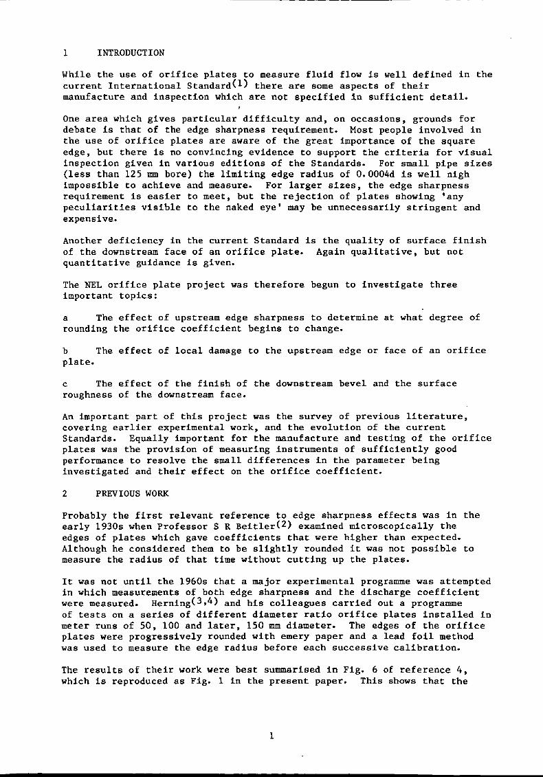
It was not until the 1960s that a major experimental programme was attemptedin which measurements of both edge sharpness and the discharge coefficientwere measured. Herning(3,4) and his colleagues carried out a programmeof tests on a series of different diameter ratio orifice plates installed inmeter runs of 50, 100 and later, 150 mm diameter. The edges of the orificeplates were progressively rounded with emery paper and a lead foil methodwas used to measure the edge radius before each successive calibration.
The results of their work were best summarised in Fig. 6 of reference 4,which is reproduced as Fig. 1 in the present paper. This shows that the
"d Upstream edge of orifice.orifice shall be square and freemay be regarded as square if itsexceeds 0.0004d."
The upstream edge of thefrom burrs or wire-edges. Itradius of curvature nowhere
effect of the edge depends only on the ratio of the radius of the edge tothe orifice diameter.
More recently, Crockett and Upp(5) made further tests using 75 mm(3-inch) diameter plates of 0.2, 0.4 and 0.6 diameter ratio and used thelead foil technique to determine the edge radius.
A little later Benedict(6) and his co-workers investigated the edgeeffect with 0.5 diameter ratio plates in a 101.6 mm (4-inch) nominal boretest line. Some of the plates were rounded to a radius of about 0.2 mm torepresent an extreme case of edge roundness. Both optical and lead foilmeasurements were used to determine the edge radius.
All the above investigations were concerned with the effect of gross changesof the edge radius. Another series of tests were made by Spencer, Calameand Singer(7) in the 1960s on the production of orifice plates to thethen current standard and the errors that could arise if care was not takenand the quality of finish required was not obtained.
3 STANDARDS
The first international standard on orifice plates(S) was published bythe International Federation of the National Standardising Associations(ISA) in 1936. It included a graph showing the effects of 'dullness' of theedge. No qualitative description of this 'dullness' was given, but thegraph is believed to have resulted from the work of Witte in the early1930s.
Owing to the difficulty of measuring edge radius, most subsequent Standardsseem to have specified that the edge be sharp and left it to the user tosatisfy himself that this has been achieved. Little guidance has also beengiven on how to machine a satisfactory sharp edge, quite a problem for somematerials, especially for small orifice diameters.
In the ASME Power Test Code(9) PTC 19.5; 5-1959 it states:
"e The inlet edge of the orifice shall be square and sharp,free from either burrs or rounding, so that when viewed withoutmagnification a beam of light is not reflected visibly by theedge."
The German Standard DIN 1952 published in 1963 commented that a reflectedray of light from a rounding radius of 0.05 romis just visible to the nakedeye(10). It was concluded that visual inspection could only bejustified if the bore diameter was greater than 125 mm at which value theedge radius would be O.0004d, the criterion given for a sharp edge.
The revised British Standard BS 1042(11) published in 1964 included thesame criterion for the sharp edge in the specification of the orifice plate.Clause 54 contained the following requirement:
Elsewhere in the same standard some guidance was given on how to producesuch an edge. Clause 40 included the statement:
2
3
"A high quality of manufacture is necessary to meet therequirements detailed in Sections Seven to Fourteen especiallyfor devices to be used in smaller sizes of pipe. The squareedge of orifice plates may conveniently be produced by taking afine cut, from the centre outwards, after the orifice has beenbored; polishing or cleaning with emery cloth is not advisable.There must of course be no burrs or wire edges."
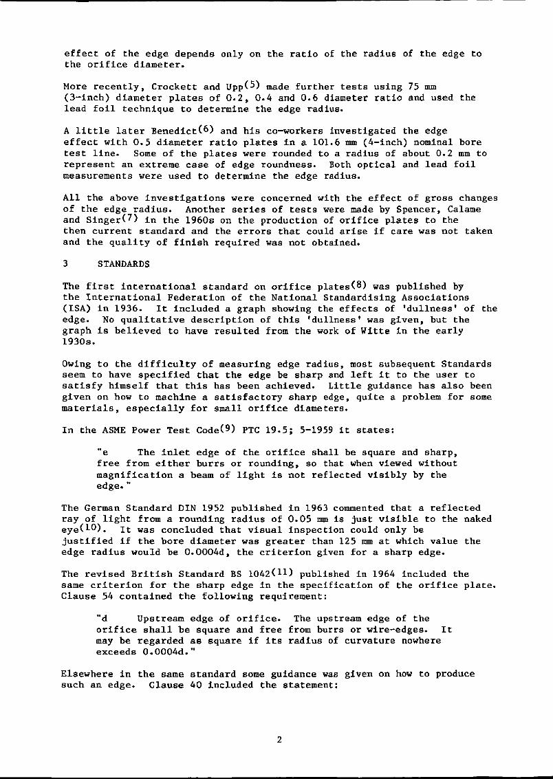
ISO 5167, 1980 which was adopted as BS 1042, 1981(12) incorporatedbasically the same message in Clause 7.1.6.
"7.1.6 Edges G, H and I
7.1.6.1 The upstream edge G and the downstream edges H and Ishall have neither wire edges, nor burrs, nor, in general, anypeculiarities visible to the naked eye.
7.1.6.2 The upstream edge G shall be sharp. It is consideredso if the edge radius is not greater than O.0004d.
If d ~ 125 mm this condition may generally be considered assatisfied by mere visual inspection, checking that the edge doesnot seem to reflect a beam of light when viewed with the nakedeye.
If d < 125 mm visual inspection is not sufficient but thiscondition may generally be considered as satisfied when theupstream face of the orifice plate is finished by a very fineradial cut from the centre outwards.
However if there is any doubt as to whether this condition issatisfied, the edge radius must be actually measured."
Fig. 2 is a reproduction of the drawing of the ISO standard orifice plateand indicates the edges G, H and I referred to the text quoted above. Noguidance is given in the Standard on how the edge radius should be measured.A Code of Practice for ISO 5167 is being prepared and this will includebrief notes on three suitable techniques, viz lead foil, casting and stylusmethods. These, and a few other possibilities, are described in thefollowing section.
4 METHODS OF MEASURING EDGE SHARPNESS
From the foregoing it is apparent that visual inspection is a valuablepre-requisite to a more sophisticated method of measurement even though itcannot give quantitative information. A truly sharp edge will not reflect abeam of light whereas if a line of light is seen it can be concluded thatthe edge is rounded.
4.1 Optical Method
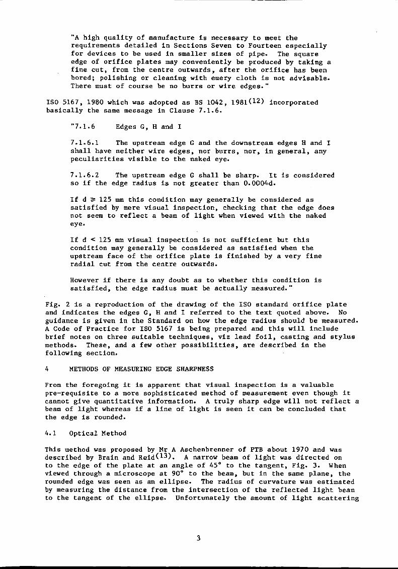
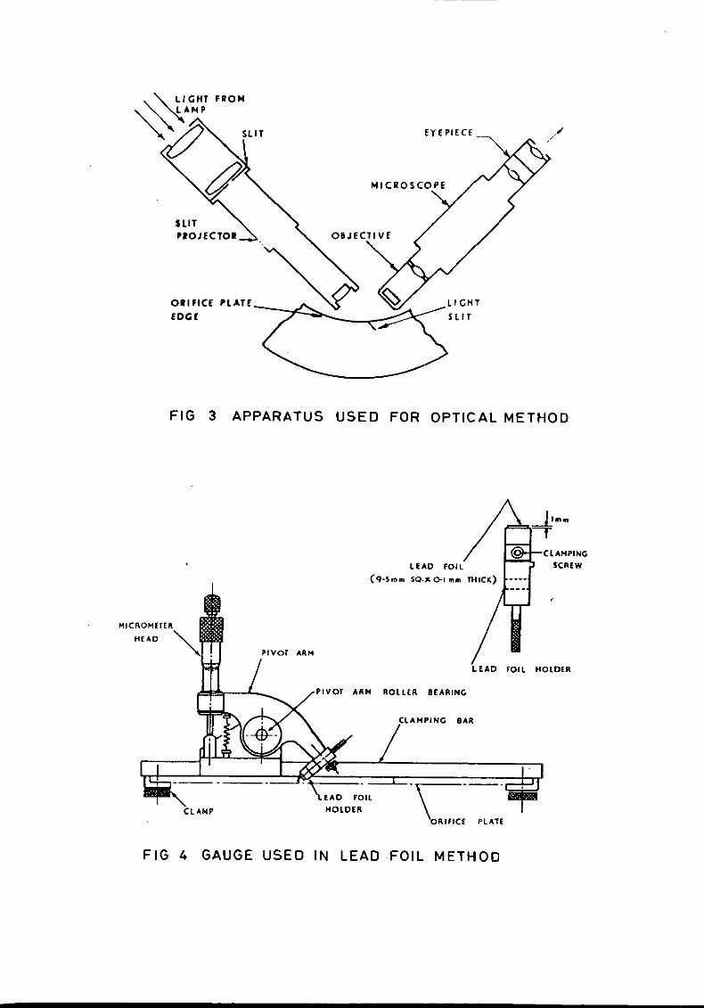
This method was proposed by Mr A Aschenbrenner of PTB about 1970 and wasdescribed by Brain and Reid(13). A narrow beam of light was directed onto the edge of the plate at an angle of 45° to the tangent, Fig. 3. Whenviewed through a microscope at 900 to the beam, but in the same plane, therounded edge was seen as an ellipse. The radius of curvature was estimatedby measuring the distance from the intersection of the reflected light beamto the tangent of the ellipse. Unfortunately the amount of light scattering
4
which occurred, blurred the image so the position of the tangent was amatter of judgement on the part of the operator.
The same method was used by Benedict(6) in the mid 70s and good resultswere claimed.
4.2 Lead Foil Technique
Herning described the lead foil technique for measurement of the orificeedge profile which he developed while working for the Ruhrgas PhysicalLaboratory in Germany. A small piece of lead foil about 0.1 mm thick wasclamped in a holder so that a small piece projected. The holder, andprotruding foil, was moved at an angle of 45° against the orifice edge togive an impression which could be projected on to a screen to facilitatemeasurement. So as not to bend the foil the depth of the impression waskept below about 0.3 mm.
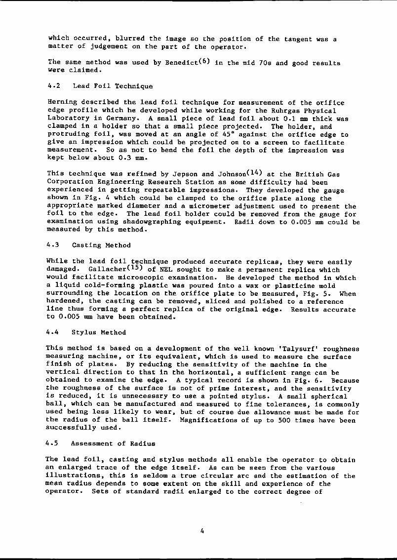
This technique was refined by Jepson and Johnson(14) at the British GasCorporation Engineering Research Station as some difficulty had beenexperienced in getting repeatable impressions. They developed the gaugeshown in Fig. 4 which could be clamped to the orifice plate along theappropriate marked diameter and a micrometer adjustment used to present thefoil to the edge. The lead foil holder could be removed from the gauge forexamination using shadowgraphing equipment. Radii down to 0.005 mm could bemeasured by this method.
4.3 Casting Method
While the lead foil technique produced accurate replicas, they were easilydamaged. Gallacher(15) of NEL sought to make a permanent replica whichwould facilitate microscopic examination. He developed the method in whicha liquid cold-forming plastic was poured into a wax or plasticine moldsurrounding the location on the orifice plate to be measured, Fig. 5. Whenhardened, the casting can be removed, sliced and polished to a referenceline thus forming a perfect replica of the original edge. Results accurateto 0.005 mm have been obtained.
4.4 Stylus Method
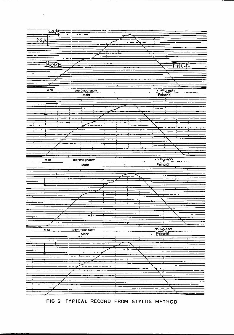
This method is based on a development of the well known 1Talysurf' roughnessmeasuring machine, or its equivalent, which is used to measure the surfacefinish of plates. By reducing the sensitivity of the machine in thevertical direction to that in the horizontal, a sufficient range can beobtained to examine the edge. A typical record is shown in Fig. 6. Becausethe roughness of the surface is not of prime interest, and the sensitivityis reduced, it is unnecessary to use a pointed stylus. A small sphericalball, which can be manufactured and measured to fine tolerances, is commonlyused being less likely to wear, but of course due allowance must be made forthe radius of the ball itself. Magnifications of up to 500 times have beensuccessfully used.
4.5 Assessment of Radius
The lead foil, casting and stylus methods all enable the operator to obtainan enlarged trace of the edge itself. As can be seen from the variousillustrations, this is seldom a true circular arc and the estimation of themean radius depends to some extent on the skill and experience of theoperator. Sets of standard radii enlarged to the correct degree of

The first phase of the test programme is to investigate the effect ofupstream edge sharpness. Beginning with a radius of about O.OOOld one plateof each diameter ratio is being successively rounded in increments towards aradius in excess of O.OOld and the plate calibrated each time.
magnification and printed on transparent plastic film can be used asoverlays on the traces of the edge in order to assist with the estimation ofthe radius. However, as those who have tried this procedure willappreciate, this is not a simple operation.
Some of the instruments used for the stylus method facilitate the use ofcurve fitting routines. Sets of x and y coordinates defining the locus ofthe stylus can be down-loaded to a micro-computer and the best fit circleobtained for the curved region. Care has to be taken to define the lengthof trace to be fitted as the points of tangency may not be clear. This maybe helped by examining a plot of the residuals obtained after subtractingthe best fit circle from the points selected. It is also a simple matter toallow for the radius of the stylus.
It should perhaps be stressed that this curve fitting routine is intended toaugment rather than replace the visual assessment of edge sharpness with theaid of overlays if appropriate. The main purpose is to accomplish the sametask, but to remove some of the subjectivity from the assessment.
5 NEL EQUIPMENT AND TEST PROGRAMME
As all known previous work was limited to pipes of diameters of 150 mm orless it was decided to base the current measurements on 300 mm (12-inch)nominal bore pipe as being more representative of the sizes commonly usedfor gas transmission. Three diameter ratios were chosen; 0.4, 0.6 and0.75, again typical of those in use, giving orifice bores of 120, 180 and225 mm respectively. A Junior orifice fitting was chosen to facilitaterepeated removal and replacement of the test plates.
The flow tests are being made in air using a set of three venturi nozzles infree inlet condition as reference flowmeters. Each nozzle is sized tocorrespond to one of the three orifice plate diameter ratios in order togive comparable ranges of differential pressure which is being measuredusing Betz manometers.
In addition to the usual measurements of orifice bore, concentricity,thickness, surface roughness etc, the edge sharpness is being measured ateight positions round the orifice using both the stylus method and by meansof cast plastic replicas. NEL has recently bought a Rank Taylor HobsonTalycontor instrument for this purpose, although the replica castingtechnique has been available for several years.
The second phase will investigate the effect of local damage introduced tothe upstream edge and gradually extended round the circumference.Calibrations will be carried out to determine how extensive the damage hasto be before the orifice coefficient is significantly affected.
The third phase will comprise a series of tests to investigate the effect ofimperfections on and roughness of the downstream side of the orifice plate.
This work is currently at an early stage and is expected to take a further12 months to complete.
5
6
REFERENCES
1 INTERNATIONAL STANDARDS ORGANISATION. Measurement of fluid flow bymeans of orifice plates, flow nozzles and venturi tubes. Geneva: ISO5167, 1980.
2 BEITLER, S. T. The flow of water through orifices. Ohio StateUniversity Engineering Experimental Station, Bulletin 89, May 3,1935.
3 HERNING, VON FR. Untersuchen zum Problem der Kantenunscharfe beiNormblended and die Segmentblenden. (Experiments on the problem ofthe edge sharpness of standard and segmental orifice plates.)Brenns~arme-Kraft, 1962, ~(3), 119-126.
4 HERNING, VON FR. and WOLOWSKI, E. Die Kantenunscharfe von Normblendenund Segmentlenden und das Ahnlichkeitsgesetz. (The edge sharpness ofstandard and segmental orifices and the laws of similarity.)Brenns~arme-Kraft, 1963, ~(1), 26-30.
5 CROCKETT, K. A. and UPP, E. L. Measurement and effects of edgesharpness on the flow coefficients of standard orifices. Trans ASME,J. of Fluids Engng, June 1973, 271-275.
6 BENEDICT, R. P., WYLER, J. S. and BRANDT, G. B. The effect of edgesharpness on the discharge coefficient of an orifice plate. TransASME, J. Engng for Power, Paper No 74-WA!FM-4, 1974, 6 pp.
7 SPENCER, E. A., CALAME, H. and SINGER, J. Der Einfluss vonKantenunscharfe und Rohrrauhigkeit auf die Durchfluss von Normblenden.Brenns~arme-Kraft, 1970, 22(2), 56-62. (Also published in Englishas: The influence of edge sharpness and pipe roughness on orificeplate coefficients. NEL Report No 427. East Kilbride, Scotland:National Engineering Laboratory, 1969.)
8 INTERNATIONAL FEDERATION OF STANDARDISING ASSOCIATIONS. Rules formeasuring the flow of fluids by means of nozzles and orifice plates.Geneva: ISO Bulletins Nos 9 and 12, 1935.
9 CHAPTER 4: FLOW MEASUREMENT. ASME POWER TEST CODES. Supplement NoPTC 19.5: 4-1959. New York: Amer. Soc. Mech. Engrs, 1959.
10 DEUTSCHER NORMENAUSSCHUSS. Durchflussmessung mit genormten Dusen,Blenden und Venturidusen. Berlin: DIN 1952, 1963.
11 BRITISH STANDARDS INSTITUTION. Methods for the measurement of flow in~pipes: Part 1. Orifice plates, nozzles and venturi tubes. London,BS 1042, Pt 1, 1964.
12 BRITISH STANDARDS INSTITUTION. Methods of measurement of fluid flowin closed conduits: Part 1. Pressure differential devices, Section1.1. Orifice plates, nozzles and venturi tubes inserted in circularcross-section conduits running full. BS 1042. Section 1.1, 1981.
13 BRAIN, T. J. S. and REID, J. Measurement of orifice plate edgesharpness. Measurement and Control, 1973, ~(9), 377-383.
7
14 JEPSON, P. and JOHNSON, E. P. A method of measuring orifice edgesharpness (ORIS). Tech. Rept-ERS.T.415. Killingworth, Newcastle, GasCouncil Engng Research Station, 1971.
15 GALLACHER, G. R. Measuring edge sharpness of orifice plates. TheEngineer, 17 May 1968, pp 783-785.
LIST OF FIGURES
1 Multipliers for flow coefficient
2 Standard orifice plate
3 Apparatus used for optical method
4 Gauge used in lead foil method
5 Stages of the casting method
6 Typical record from stylus method.

L--_+--~--4---+-~~-+--~--+---~-+--~--+-~k-~~~~~~+(or, -.....................
l,05;1-----j'--t---+---+--+---+---t-----j~_+-_+_:;;l·._4V=--_I_-+-+____i~ V-~l~·~---j~-+---+---f---+---+--~~~~=--+---t--4---+--~--+----i1 ...l/··')·';'".r7,OJf----j---+---+---+--+"....::.~-t____t-_+---+--+--~'-'-'i--+-~~ .".~< .\'ormbkndtll:.~ io _.v Q D - ~omm [11d! Vt1----4---.-. ,......-.~-"4_,,--_+_--4--+-__+ • D - 1011mm (II
,,·1 J>:!' . • D - 100 mm (Zaltltlua/d -I lind [I»~07 ... ~ o'l! • .. D - J~I} mm (ntue V.""Chl)~ T. r.c.,B~ ..dtn:.~ . i · D - ISO min ("~I" J"t"uch.)
;0170 . 1
~
FIG , MULTIPLIERS FOR FLOW COEFFICIENT
THICKNESS E OF THE. PLATEir'-,'
UPSTREAM FACE A / DOWNSTREAM FACE B
/--.- ~I / tL...- __
V (',\INGLE OF~_. ~ BEVELF
I -- THICKNESS e OF THE ORIFICE
DIRECT ION OF FLOW
/ /{DOWNSTREAM</ EDGES H AND I
UPSTREA~ VEDGE G
--L --,I /1r-------
//-...
FIG 2 STANDARD ORIFICE PLATE
¢D
2 J s 7 ,r,..Id.s 11 1J 1'1 15-11)"10 11
AXIAL CENTRE -LINE_.- . ~.---.--.--
,.
fYEPIECf_
SLITPIOJECTOR
ORifiCEfoaE
FIG 3 APPARATUS USED FOR OPTICAL METHOD
LEAD FOIL
(q·s ...... SQ·)l.O·1 m ... rHICK)
CLAMPING
SCREW
L tAD fOI L HOLDER
PIVOT ARM ROLLtR SEARING
lAMPINC SAR
FIG 4 GAUGE USED IN LEAD FOIL METHOD

Co} .HERE,.,CE LlNH Off OIIFlCE I'LAn
(~) CASTING WITH IHEllNer LINE "'HDIDENTlflCA TlO~ HUH IE IS
(a) C ...SlING I'lfPAIEO 'OR .... 'ICINGWill'! (I'll( OTf .2&
OIIfICIIOU
U'SlIEIUo! FACE 0'
ORI'ICElORE
(Io) WAX CUP READY '0' CASTING
WAXcur
CASTING "'Tn UHOVAL FRONORifICE I'L HI
(.) CON'L ( TfD TfCHffOVJT r'IICOTlCOM'OSITf CASTING
t-~----CA ...f .. / Mlc.oscorE
'(PLI,A 0' orifiCE !'L"'T[ fDGE
U'STrE ...M 'ACI Of 0111 ICE rLATf
fPlKOTf I~ &
FIG 5 STAGES OF THE CASTING METHOD
M50 oe~!"Io;;raoh__Mahr
mltigraph- . Feiiiproi ---
"7
z;;;;;;;.7Z >
$,
Ill~
/'-/
perthog'aoh-------Matv'
"'50 ""I"graphFein-pnjr~~
/-
rT\,!ligraph------Feinpj{,t,,----
.1
/'
':s"/ S1SS
\/' s
FIG 6 TYPICAL RECORD FROM STYLUS METHOD