TMENT OF ENERGY - ntrs.nasa.gov · PDF fileand corrosion. Exhaust gases in the cement industry...
108
NASA-CR- 1695 13 19830005373 AN ASSESSMENT OF GAS-SIDE FOULING IN CEMENT PLANTS BY W. J. Marner September 1982 Work Performed Under Contract No. A107-801D l 21 38 LIBRARY COPY Jet Propulsion Laboratory California l nstitute of Technology Pasadena, California LANGLEY RESEARCH CENTER LIBRARY, NASA HAMPTON, VIRGINIA U. S. DEPAR\TMENT OF ENERGY https://ntrs.nasa.gov/search.jsp?R=19830005373 2018-05-04T11:04:47+00:00Z
Transcript of TMENT OF ENERGY - ntrs.nasa.gov · PDF fileand corrosion. Exhaust gases in the cement industry...

NASA-CR- 1695 13 19830005373
AN ASSESSMENT OF GAS-SIDE FOULING I N CEMENT PLANTS
BY W. J. Marner
September 1982
Work Performed Under Contract No. A107-801 D l 21 38
LIBRARY COPY Jet Propulsion Laboratory California l nstitute of Technology Pasadena, California LANGLEY RESEARCH CENTER
LIBRARY, NASA HAMPTON, VIRGINIA
U. S. DEPAR\TMENT OF ENERGY
https://ntrs.nasa.gov/search.jsp?R=19830005373 2018-05-04T11:04:47+00:00Z

DISCLAIMER
"This report was prepared as an account of work sponsoredby an agency of the UnitedStates Government. Neither the UnitedStatesGovernmentnor any agency thereof, nor anyof their employees,makesany warranty, expressor implied,or assumesany legalliabilityorresponsibilityfor the accuracy,completeness,or usefulnessof any information,apparatus,product, or processdisclosed, or representsthat its use would not infringeprivatelyownedrights. Referenceherein to any specific commercial product, process, or serviceby tradename, trademark, manufacturer, or otherwise,does not necessarilyconstitute or imply itsendorsement, recommendation,or favoringby the United StatesGovernmentor any agencythereof. The views and opinions of authors expressedherein do not necessarilystate orreflect those of the UnitedStatesGovernmentor any agencythereof."
This report has been reproduced directly from the best available copy.
Available from the National Technical Information Service, U. S. Department of Commerce, Springfield,Virginia 22161.
Price: Printed Copy A06Microfiche A01
Codes are used for pricing all publications. The code is determined by the number of pages in thepublication. Information pertaining to the pricing codescan be found in the current issuesof the followingpublications, which are generally available in most libraries: Energy Research Abstracts, (ERA);Government Reports Announcements and Index (GRA and I); Scientific and Technical Abstract Reports(STAR); and publication, NTIS-PR-360availablefrom (NTIS) at the above address.

JPL Publication 82-83 DOE/ID/12138-2
(JPL-PUBL-82-83)
(DE83001426)Dis[ribution Category UC-95f
An Assessment of Gas-Side Foulingin Cement Plants
W.J. Marner
September 1982
Prepared for
U.S. Department of Energy
Idaho Operations Office
Through an Agreement withNational Aeronautics and Space Administration
by
Jet Propulsion LaboratoryCalifornia Institute of TechnologyPasadena, California


ABSTRACT
The cement industry is the most energy-intensive industry in the United
States in terms of energy cost as a percentage of the total product cost. The
purpose of this study is to provide an assessment of gas-side fouling in cement
plants with special emphasis on heat recovery applications. In the present
context, fouling is defined as the buildup of scale on a heat-transfer surface
which retards the transfer of heat and includes the related problems of erosion
and corrosion. Exhaust gases in the cement industry which are suitable for heat
recovery range in temperature from about 400 to 1300 K, are generally dusty, may
be highly abrasive, and are often heavily laden with alkalies, sulfates, and
chlorides. Particulates in the exhaust streams range in size from molecular to
about I00 u m in diameter and come from both the raw feed as well as the ash in
the coal which is the primary fuel used in the cement industry. The major types
of heat-transfer equipment used in the cement industry include preheaters,
gas-to-air heat exchangers, waste heat boilers, and clinker coolers. At the
present time, the trend in this country is toward suspension preheater systems,
in which the raw feed is heated by direct contact with the hot kiln exit gases,
and away from waste heat boilers as the principal method of heat recovery. The
most important gas-side fouling mechanisms in the cement industry are those due
to particulate, chemical reaction, and corrosion fouling. Particulate transport
mechanisms which appear to be of greatest importance include laminar and
turbulent mass transfer, thermophoresis, electrophoresis, and inertial impaction.
Chemical reaction mechanisms of particular importance include the deposition of
alkali sulfates, alkali chlorides, spurrite, calcium carbonate, and calcium
sulfate. At sufficiently low temperatures, sulfuric acid and water can condense
on heat exchanger surfaces which can cause corrosion and also attract
particulates in the flow. The deleterious effects of gas-side fouling in cement
plants are due to: (I) increased capital costs, (2) increased maintenance costs,
(3) loss of production, and (4) energy losses. A conservative order-of-
magnitude analysis shows that the cost of gas-side fouling in U.S. cement plants
is $0.24 billion annually. Recommendations for further work in the area of
gas-side fouling in cement plants include a comprehensive study of gas-side
fouling mechanisms, as well as several other prioritized short-term and long-term
projects.
iii

ACKNOWLEDGMENTS
The informationfor this study was obtainedthrougha literaturesearch,
personal contacts,and visits to selected industriesin the cement industry. It
is a pleasureto acknowledgewith appreciationthe followingpersonswho provided
technicalinput for this report: James M. Archibald,Smith EngineeringCompany;
MohammedBhatty, PortlandCement Association;Ron E. Evans, CaliforniaPortland
Cement Company;C.O. Fleming,Gifford-Hill& Company, Inc.; Robert Krowech,
Deltak Corporation;Norman Maycock,Martin Marietta Cement;Errol Raught,Jr.,
Allis-ChalmersCorporation;and Jack Reithmuller,Tera EngineeringCompany.
MarilynHalasz of the PortlandCement Associationwas very helpfulin obtaininga
list of referencesdealingwith heat recoveryin the cement industry,includinga
number of foreigntranslations. Specialthanks are due to John Kane of the
National GypsumCompany, who introducedthe author to a number of personsat the
17th InternationalCement Seminarin Chicago, Illinois,December 6-9, 1981, and
to John Maberry of Smith EngineeringCompany (formerlyof the Fuller Company)who
providedthe author with many detailson the heat recoveryequipmentused in the
cement industryas well as cement plant operationsin general. DonaldRapp of
the Jet PropulsionLaboratoryand LawrenceCasper of EG & G Idaho, Inc. (now with
Honeywell, Inc.) reviewedthe manuscriptand made many helpful suggestions.
Finally, Huyen Ha, Dee Darrow, MadeleineLipofsky,and llarrietKramerwere
responsiblefor typing the manuscript.
This work was performedby the AppliedMechanicsTechnologyand
InstrumentationSections,Jet PropulsionLaboratory (JPL),CaliforniaInstitute
of Technology,Pasadena,California. This projectwas sponsoredby the U.S.
Departmentof Energy, Officeof Energy SystemsResearch,Energy Conversionand
UtilizationTechnology (ECUT)Program,under InteragencyAqreement
DE-AIO7-80ID12138,AmendmentAO01, throughNASA Task Order RD 152, Amendment 300.
Technicalmonitor for the projectwas W.H. Thielbahr,Chief, Energy Conservation
Branch,U.S. Departmentof Energy, Idaho OperationsOffice, Idaho Falls, Idaho,
whose supportand continuinginterestare deeply appreciated.
iv

NOMENCLATURE
A constant in Eq. 5-23
Ao constant in Eq. 5-7
B constant in Figure 5-3
Bo constant in Eq, 5-24
c particle concentration
dp particle diameter
D diffusion coefficient
E activation energy
f friction factor
J particle mass flux
kg gas thermalconductivity
kp particlethermal conductivity
kt transportcoefficientof the particlesnear the surface
mp particlemass
p stickingprobability
Pr Prandtlnumber
q electricalcharge
R gas constant
Rf foulingresistancew
Rf asymptoticfoulinqresistance
Rep particleReynolds number
Sc Schmidtnumber
S stoppingdistance
S+ dimensionlessstoppingdistance
t time
V fluid velocity

Vp particle velocity
Vt thermophoretic particle velocity
Vpn particle velocity normal to surface
x ratio of observed to predicted deposition coefficient with p = I
y spatial coordinate normal to surface
coefficient defined by Eq. 5-3
vT temperature gradient
eddy diffusivity for turbulent mass transfer
_o permittivity in free space
gas viscosity
gas kinematic viscosity
p particle densityP
_w wall shear stress
_d fouling deposition rate
fouling removal rater
fouling deposit strength
vi

CONTENTS
Page
1. INTRODUCTION 1-1
2. THE MANUFACTUREOF PORTLANDCEMENT 2-I
3. CHARACTERIZATIONOF WASTEHEATEXHAUSTSTREAMSIN CEMENTPLANTS...... 3-i
3.1 TYPE OF FUEL 3-1
3.2 COMPOSITIONOF THE RAWMATERIALS 3-4
3.3 TEMPERATUREANDVOLt]METRICFLOWRATES- 3-5
3.4 CHEMICALCOMPOSITION 3-7
3.5 PARTICLEDENSITYANDSIZE DISTRIBUTION 3-9
4. HEAT-RECOVERYEQUIPMENTUSED IN CEMENTPLANTS 4-1
4.1 PREHEATERS 4-I
4.2 GAS-TO-AIR HEAT EXCHANGERS 4-4
4,3 WASTEHEAT BOILERS.............................................. 4-5
4.4 CLINKER COOLERS 4-7
5. GAS-SIDE FOULING MECHANISMS 5-1
5.1 CLASSIFICATION OF FOULING 5-1
5.2 PARTICULATE FOULING DEPOSITION MECHANISMS 5-3
5.3 CORROSION, CORROSIONFOULING, ANt) CHEMICAL REACTIONFOULING MECHANISMS...................... 5-12
5.4 REMOVALMECHANISMSAND MODELS.... 5-23
5.5 EROSION......................................................... 5-26
6. GAS-SIDE FOULING EXPERIENCE IN CEMENTPLANTS......................... 6-1
6.1 PREHEATERS........................................... 6-1
6.2 GAS-TO-AIR HEAT EXCHANGERS...................................... 6-6
6.3 WASTE HEAT BOILERS.............................................. 6-9
vii

7. DELETERIOUSEFFECTSOF GAS-SIDEFOULINGIN CEMENTPLANTS 7-1
8, CONCLUSIONSANDRECOMMENDATIONS........... 8-1
8.1 SUMMARYOF MAJORFINDINGS 8-1
8.2 RECOMMENDATIONSFORFURTHERWORK 8-6
8.3 CONCLUDINGREMARKS 8-9
REFERENCES................................................ R-1
viii

FiquresPage
2-1. Schematic Drawing of Kiln Used in Cement Manufacturingby Simple Wet and Dry Processes ............................... 2-3
2-2. Fuller-Humboldt Suspension Preheater with and withoutPrecalciner .................................... 2-6
4-1. Schematic Drawings of the Smidth, Polysius, Krupp, andMiag Suspension Preheaters .................... 4-3
5-1. Effect of Particle Size and Velocity on DepositionAccording to Beal's Model....................... 5-11
5-2. Schematic lllustration of Gas-Side Fouling Deposit andCorrosion on Boiler Tube.............................. 5-17
5-3. The Deposition Rate of Sodium Sulfate at 1.0 PercentExcess Air ........................................ 5-19
5-4. The Kern-Seaton Fouling Model lllustrating the AsymptoticFoulinq Resistance Behavior .................................... 5-24
ix

TablesPage
2-1. Portland Cement Clinker Compounds 2-2
2-2. Reactions in the Cement Kiln and the Temperature Rangesat Which They Occur. 2-3
2-3. Summaryof Cement Plants Operating in U.S. during 1980 2-7
3-1. Summaryof Fuels Used in Cement Plants in U°S. in 1980........ 3-2
3-2. Ultimate Analysis of Various Ranks of Coal 3-3
3-3. Typical Limits of Ash Composition in U.S. BituminousCoals 3-4
3-4. Range of Principle Raw Materials Used in MakingPortland Cement- 3-5
3-5. Summaryof Cement Plant Exhaust Gas Streams 3-6
3-6. Chemical Analyses of Representative Kiln Dusts 3-8
3-7. Representative Particle Size Distributions in VariousCement Plant Streams 3-10
3-8. Density of Important Particulates in Cement Kiln Dusts 3-10
4-1. Air Distribution in Grate Clinker Coolers for DifferentType Kiln Systems--- 4-10
7-1. Estimated Value of Energy in U.S. Cement Plant ExhaustGas Streams................................................... 7-4
7-2. Summaryof Estimated Annual Costs in U.S. Cement PlantsDue to Gas-Side Fouling, Corrosion, and Erosion 7-6
X

SECTION1
I NTRODUCTI ON
Heat recoveryfrom medium and high temperatureexhaustgas streamsis
essentialfor the efficientoperationof most industrialenergy conversion
systems. However,in many instancessuch gases are dirty,contain corrosive
components,and are laden with particulateswhich resultsin severegas-side
foulingproblems. In the presentcontext,foulingmay be definedas the buildup
of scale on a heat exchangersurfacewhich retardsthe transferof heat and
includesthe associatedproblemsof corrosionand erosion. Although gas-side
foulinghas been identifiedas a major problemin heat-recoverysystems,
inadequateresearchhas been done in this area. The purposeof the present
study is to assess the state-of-the-artof gas-sidefoulingin an important
heat-recoveryenvironment,namely cement plant exhausts. At the presenttime,
the cement industryis the most energy-intensiveindustryin the United States
in terms of energy cost as a percentageof the total productcost (Reference
I-i).
The major objectivesof this study are:
(1) Characterizethe waste heat exhauststreamsin cement plants as
to: type of fuel, chemical compositionincludingparticulates,
temperature,and flow rate.
(2) Determinepast and presentexperiencewith varioustypes of
heat-recoveryequipmentin cement plants and evaluatethe
associatedgas-sidefoulingproblems.
(3) Identify and attempt to quantify the deleterious effects of
gas-side fouling in cement plants including increased energy
consumption, increased material losses, and the loss of
production.
1-1

(4) Recommenda well-defined R&Dprogram for gas-side fouling in cement
plants which includes both short-term and long-term applied research
projects.
The information described above was obtained through a literature survey,
personal contacts, and visits to selected industries in the cement industry.
Visits were made to Smith Engineering Company, Duarte, California, Riverside
Cement Company, Oro Grande, California, and the Portland Cement Association,
Skokie, lllinois. In addition, the author attended the 17th International Cement
Seminar which was held in Chicago, lllinois, on December 6-9, 1981. Attendance
at this Seminar afforded a broad exposure to cement-industry technology and the
opportunity for personal interactions with a number of representatives from the
cement industry.
1-2

SECTION2
THE MANUFACTUREOF PORTLANDCEMENT
Although the use of cement dates back to antiquity, the portland cement
industry as it is known today apparently started in 1824. In that year Joseph
Aspdin, an Englishman, patented an artificial cement made by the calcination of
an argillaceous limestone. He called this portland because concrete made from
it resembled a famous building stone obtained from the Isle of Portland near
England (Reference 2-1).
Portlandcement is made by mixing and calcining (heatingto a high
temperatureto drive off volatilematter)materialswhich containlimestone,
silica,alumina, and iron oxide, in the proper proportions,to a temperature
between 1725 and 1875 K. ASTM has definedportlandcement as (Reference2-2):
a hydrauliccement producedby pulverizing
clinkerconsistingof hydrauliccalcium
silicates,usuallycontainingone or more
forms of calciumsulfateas an interground
additive.
Eight types of portland cement are recognized in the United States depending on
the varying amounts of the clinker compounds listed in Table 2-1 and the
addition of air-entraining agents. As may be seen from Table 2-1, lime
compounds of silica, alumina, and iron account for all but a small fraction of
the constituents of portland cement clinker.
Heating of the finely-ground feed takes place in a rotary kiln as shown
in Figure 2-1. The kiln consists of a large cylindrical shell, which is lined
with firebrick, typically with a diameter of 2.13 to 7.32 m. The kiln
2-1

Table 2-1. Portland Cement Clinker Compounds (Reference 2-1)
Name Formula Abbreviation
Dicalcium Silicate 2CaO'SiO2 C2S
Tricalcium Silicate 3CaO'SiO2 C3S
Tricalcium Aluminate 3CaO'A1203 C3A
Tetracalcium Aluminoferrite 4CaO'AI203 "Fe203 C4AF
Magnesium Oxide in Free State MgO MgO
axis is inclined at a slight angle with the horizontal, typically 20.8 to 83.2
mm per m. The kiln is driven through a spur pinion meshing with a large girth
gear and rotates slowly on the order of i to 3.5 rpm. The raw feed is
introduced at the upper end of the kiln and heat is supplied at the lower end of
the kiln by a hot flame. Thus, the hot combusted gases flow in a countercurrent
direction to the feed in the kiln.
As the raw material, typically occupying 7 to 8 percent of the kiln
volume, moves through the kiln under the rotary action of the kiln, a series of
chemical changes take place which produce the formation of marble-sized clinker.
The most important reactions which take place in the kiln, and the temperatures
at which they occur, are given in Table 2-2. (Reference 2-3). At the exit of
the kiln, the clinker which is at a temperature of about 1775 K, passes through
a clinker cooler where it is cooled by ambient air. Portland cement is then
made by grinding the clinker very finely and mixing it with up to five percent
gypsum (calcium sulfate dihydrate, CaSO4.2H20) to control the set of the
cement.
2-2

Table 2-2. Reactionsin the Cement Kiln and the TemperatureRanges at Which They Occur (Reference2-3)
Reaction TemperatureRange,K
Evaporation of Free Water 375-395
Evolution of Combined Water Up to 775
Evolution of CO3 from Limestone (Calcination) 1075-1125
Formation of C3S 1075-1175
Formation of C3A and C4AF 1370-1480
Formation of C3S 1535-1730
RAWFEED
CHAINS
ZONES: I DRYING J PREHEATING I CALCINING I BURNING I COOLING I
Figure 2-1. Schematic Drawing of Kiln Used in Cement Manufacturingby Simple Wet and Dry Processes (Reference 2-3)
2-3

In the Llnited States two basic processes, the wet process and the
long-dry process, are used to make portland cement. In addition, two variations
of the long-dry process are becoming increasingly popular. Therefore, the four
types of processes are:
(1) Wet process.
(2) Long-dry process.
(3) Suspension preheater dry process.
(4) Suspension preheater/precalciner combination process.
In the wet process the raw materials are proportioned, ground with water,
blended, and fed into the kiln as a slurry. In the dry process the raw
materials are dried, proportioned, ground, blended, and fed into the kiln
essentially as a dry mixture. In the wet process the slurry encounters a system
of chains which are attached to the surface of the kiln. _ As the kiln rotates,
the chains become coated with the slurry and heat is transferred from the hot
combustion gases which dries the raw feed. The raw mix is then converted to
nodules which move down the kiln through the preheater, calcining, and burning
zones as shown in Figure 2-1. On the other hand, in the dry process very little
drying is required before the raw feed passes through a mixing device -- such as
chains, lifters, or trefoils -- prior to moving through the calcining and
burning zones.
Although there are several types of preheaters, the trend is toward the
use of suspension preheaters, so-called because the raw feed particles are
suspended in a series of cyclones, usually four, in which the feed moves in a
countercurrent flow to the upward moving exhaust gases. Thus, the suspension
preheater provides for a direct contact heat transfer mechanism between the hot
kiln exhaust gases and the cold feed. A typical arrangement of a four-cyclone
unit for a Fuller-Humboldt preheater is shown in Figure 2-2. As shown, a
sequence of suspension and separation is repeated through each cyclone until the
preheated, partially calcined feed enters the kiln at about 1075 K where
calcination and the burning stages are completed.
A fairly recent innovation is the addition of a precalciner to the
suspension preheater, accomplished by introducing an auxiliary fuel burning
chamber in the final stages of the preheater, designated by the letters "PC" as
2-4

as shown in Figure 2-2. A suspensionpreheaterwith four cyclonestageswill
accomplishabout 50 percentof the preheatingand calciningof the raw feed
before it enters the kiln. Introductionof a precalcinerwill increasethis
processto about 90 percent. Thus, in additionto recoveringenergy from the
kiln exhaust gases,the use of preheatersand precalcinersallow for a much
shorterand smallerdiameter kiln for any given capacity.
Also shown in Figure 2-2 is a bypass at the kiln gas flow exit just below
the suspensionpreheatersystem. The purposeof this bypass,frequentlycalled
the alkali or kiln bypass,is to limit the levelsof chloride,alkalies,and
sulfur in the kiln feed. Typically,the quantityof hot gases which are
bypassedaround the preheaterranges from 5 to 25 percent,dependingupon the
rate of feed, gas flowrate,and specificoperatingconditions.
A summary of the number of cement plants operating in the United States
during 1980 is given in Table 2-3, categorized according to the type of process.
This table was constructed from data given in Reference 2-4. Although the
number of wet and dry kilns is about equal at the present time, the trend is
away from wet kilns and toward dry kilns because the latter are more efficient
from an overall energy standpoint. In 1973, 58 percent of the kilns were of the
wet process type. At that time only five percent of the long-dry process kilns
utilized preheaters compared to 23.3 percent in 1980. Also, the trend in the
United States is toward fewer, but larger, cement kilns. In 1980 there were 327
kilns, a reduction of 26.5 percent compared to the 445 kilns which were in
existence in 1973. However, the annual clinker capacity of 86,337,000 short
tons in 1980 was 1.4 percent greater than in 1973, even though there were 118
fewer kilns. In the cement industry the short ton is widely used as a measure
of weight: i short ton = 2000 Ib m = 0.907 metric ton.
2-5

PRECIPITATOR
i
_/.ILN _XH. FAN ---r,_
Figure 2-2. Fuller-Humboldt Suspension Preheater withand without Precalciner (Reference 2-3)
2-6

Table 2-3. Summaryof Cement Plants Operating in U.S.during 1980 (Reference 2-4)
Process Number Annual Clinker Capacity Percent of Totalof Kilns (I,000 Short Tons*) Annual Capacity
Wet 175 42,564 49.3
Long-Dry 104 23,613 27.4
Preheater** 48 20,160 23.2
Total 327 86,337 100.0
* 1 short ton = 2000 Ibm = 0.907 metric ton
** Includes eleven combination preheater-precalciner systems with an annualclinker capacity of 7078 (I,000 Short Tons).
2-7


SECTION3
CHARACTERIZATIONOF WASTE HEAT EXHAUSTSTREAMSIN CEMENTPLANTS
The purpose of this section is to characterize the various waste heat
exhaust streams in cement plants. Basically, the quantity and quality of
exhaust gases in cement plants depends on a number of factors including the:
(I) Type of fuel.
(2) Fuel rate in the kiln and precalciner.
(3) Composition of the raw materials.
(4) Quantity of excess air.
(5) Heat transfer processes within the kiln.
(6) Amount of water, if any, in the raw materials.
(7) Specific process which produces the exhaust gas stream.
From the standpoint of heat recovery and the associated gas-side fouling
problems, the specific parameters of interest include the type of fuel, the
composition of the raw materials, the volumetric flowrate and temperature of the
various exhaust gas streams, and the chemical composition of the various exhaust
gas streams, including the particle density and size distribution.
3.1 TYPE OF FUEL
The primary and alternate fuels used in cement plants in the United
States during the 1980 calendar year are given in Table 3-1. Based on this
data, 87 percent of the plants in this country use coal as the primary fuel at
the present time. Only I0 percent use natural gas as the primary fuel an_ only
one percent use oil. With the cost of oil and natural gas increasing far more
rapidly than coal, it is expected that this trend toward coal in the cement
industry will continue. In addition to these major fuels, there is also some
interest in using a variety of waste materials as kiln fuel (Reference 3-1).
Included in this cateqory are such fuels as: waste lube oil, wood chips and
3-I

Table 3-1. Summaryof Fuels Used in Cement Plants in U.S.in 1980 (Reference 2-4)
Primary Fuel Alternate Fuel
Fuel Type Number of Clinker Percent Number of Clinker PercentPlants Capacity of Total Plants Capacity of Total
(I000 Ton) Capacity (i000 Ton) Capacity
Coal 121 74,724 87 3 1,165 1
Oil 3 1,164 1 22 16,451 19
Natural Gas 12 8,219 i0 44 22,794 26
Coal, Oil 0 0 0 i 312 0
Oi I, 0 0 0 24 16,916 20Natural Gas
Total 142 86,337 100 94 57,638 66
sawdust, auto tires, acid sludge, and municipal waste. One of the major
problems in utilizing such waste materials is the chemical non-uniformity of
these sources. Although such waste materials will never account for more than a
small fraction of the fuel used in cement kilns, this topic will probably
continue to receive some attention in the future.
Since the primary fuel presently being used in U.S. cement plants is
coal, with a continuing trend in this direction, the emphasis in this report is
placed on coal as the fuel. Coal may be classified according to the four major
ranks which are anthracite, bituminous, sub-bituminous, and lignite. Of these
four types of coal, the bituminous rank is the most plentiful and the most
widely used.
3-2

Coal of any rank consists primarily of carbon, with varying amounts of oxygen,
hydrogen, nitrogen, sulfur, and ash as indicated in Table 3-2. The presence of
sulfur and the various mineral constituents in the ash are ultimately
responsible for the fouling, corrosion, and erosion problems which occur after
the combustion process. Coal ash typically makes up about 9 to 10 percent of
the coal, although this percentage can vary significantly, and consists
primarily of Si02, A1203, and Fe203, with smaller amounts of CaO, MgO, Til)2,
Na20, K20, and SO3 as indicated in Table 3-3. Additional details on the
properties and characteristics of coal may be found, for example, in Reference
3-2.
Table 3-2. Ultimate Analysis ef Various Ranks of Coal (Reference 3-3)
Representative Range of Constituents, Percent by Weight
Rank
Carbon Oxygen Hydrogen Nitrogen Sul fur Ash
Anthracite 64.2-94.7 1.8-14.5 0.5-3.9 0.2-1.8 0.3-1.9 7-5-21.8
Bituminous 59.7-90.7 2.3-20.1 4.4-5.7 1.0-1.7 0.8-5.0 5.2-11.7
Sub- 50.5-76.0 14.8-35.5 4.6-6.0 0.7-1.5 0.3-1.8 3.6-9.1Bituminous
Lignite 40.6-70.9 19.4-45.1 4.5-6.9 0.6-1.1 0.9-1.6 5.9-9.4
3-3

Table 3-3. Typical Limits of Ash Composition in U.S. Bituminous Coals(Reference 3-4)
Constituent Chemical Formula Percent
Silica SiO2 20-60
Alumina AI203 10-35
Ferric Oxide Fe203 5-35
Calcium Oxide CaO 1-20
Magnesium Oxide MgO 0.3-4
Titanium Dioxide TiO2 0.5-2.5
Alkalies (Potassium Na20, K20 1-4and Sodium)
Sulfur Trioxide SO3 0.1-12
3.2 COMPOSITIONOF THE RAWMATERIALS
The raw materials used for making portland cement are a mixture of
calcareous (containing calcium carbonate) and argillaceous (like or containing
clay) in the proper proportions to provide the chemical compositions for
burning or sintering. The calcareous materials presently in use include
primarily limestone, along with some marl, cement rock, and chalk. The
argillaceous materials include clay, shale, blast-furnace slag, and ashes. The
principal raw materials used in producing portland cement are given in Table
3-4. The primary consituent is calcium carbonate, typically ranging from 68 to
78 percent, which undergoes calcination according to the reaction
CaCO3 --> CO2 + CaO (3-1)
to produce lime, CaO, which is the primary constituent of portland cement. In
addition to the principal constituents given in Table 3-4, there are also
generally trace amounts of manganese, strontium, titanium, phosphate, and
copper.
3-4

Table 3-4. Range of PrincipalRaw MaterialsUsed in Making PortlandCement (Reference3-5)
Constituent Chemical Formula Range, Percent
Silica SiO2 11.5-17.0
Alumina Al203 1.6- 5.0
Ferric Oxide Fe203 1.0- 4.0
Calcium Carbonate CaCO3 68.0-78.0
Magnesium Oxide flgO 3.0- 5.5
Alkalies (Potassium K20, Na20 0.4- 1.0and Sodium)
3.3 TEMPERATUREAND VOLUMETRICFLOWRATES
The exhauststreamswhich offer the greatestpotentialfor heat recovery
in cement plantsare those from the kiln, the preheater,and the clinker
cooler. The approximate volumetricflowratesand temperaturelevels for the
long-dryprocess,wet process,and preheaterprocessare shown in Table 3-5
which was adapted from References3-6 and 3-7.
In general, exhaust gases from the kiln or preheater exit are dusty but
not particularly abrasive. The temperature of the exhaust gases from the wet
process is lower than for the long-dry process because of the very high
moisture content in the wet-process feed. In the preheater process the exhaust
gas temperature of 645 K leaving the preheater is considerably less than that
leaving the kiln of the long-dry process because a portion of the energy in the
former case is utilized to heat the feed in the preheater.
The gases leavinq the clinker cooler are both dusty and extremely
abrasive. A portion of these gases is recuperated and used for secondary air
in the kiln and the remaining air is vented to the atmosphere through a baghouse.
Many preheaterprocesskilns have a bypass provisionas was shown in
Figure2-2. The purposeof this bypass is to remove a portionof the
undesirableconstituentssuch as alkalies,sulfates,and chloridesfrom the
3-5

Table 3-5. Summaryof Cement Plant Exhaust Gas Streams(Adapted from References 3-6 and 3-7)
Process Exhaust Physical Approximate Approximate Gas EnergyGas Source Characteristics Volumetric Temperature, Content,*
Flowrate, K kW-hr perStandard m3 short tonper short of clinkerton of clinker
Long-Dry Kiln Exit Dusty 1810 865 440(900 shorttons per24-hourday) Clinker Dust & Highly 1980 445 106
Cooler Abrasive
Wet Kiln Exit Dusty 3960 535 380(900 shorttons per24-hourday) Clinker Dusty & Highly 1130 41() 4/
Cooler Abrasive
Preheater Preheater Dusty 1240 645 176(3,000 Exitshorttons per Clinker Dusty & Highly 1980 480 12624-hour day Cooler Abrasive
Bypass Dusty & Highly 140"* 1285 56Contaminatedwith Alkalies,Sulfates, &Chlorides
All Finish MillProcessess & Separator 960 365 26
* Reference temperature 289 K
** Bypass flowrate calculated assuming a 10 percent bypass.
3-6

system. This removal is achieved by locating the bypass at the top of the kiln,
thus allowing the lighter undesirable gases to leave the kiln-preheater system.
These gases then enter a quench chamber where ambient air is used to quickly
cool the objectionable compounds. Thus, the contaminants pass quickly from the
vapor state to the solid state and avoid the undesirable liquid state (Reference
3-8). In most bypass systems the amount of exhaust gas leaving the kiln which
is bypassed typically varies from about 5 to 25 percent by volume, or even
higher, depending on the level of contaminants. The volumetric flowrate in Table
3-2 has been calculated on the basis of a I0 percent bypass as indicated. The
important point with regard to this particular gas stream is the very high
temperature level of about 1285 K. For this reason, even though the gases may
be highly contaminated, there is considerable interest in trying to recover a
portion of the energy from this high-temperature stream.
Finally, the gases leaving the finish mill and separator, where the
clinker is finely ground and mixed with gypsum to produce cement, is about 365
K. However, in comparison with the other gas streams available, there is not
too much interest in this particular gas stream at the present time because of
the very low temperature level.
3.4 CHEMICALCOMPOSITION
The chemical composition of the various exhaust streams is very
important. Of course, this will vary from plant to plant, depending especially
on the composition of the feed and the type of fuel. The chemical analyses of
four typical kiln dusts, taken from Reference 3-9, are given in Table 3-6. The
four dusts are designated as high sulfate (Dust H), high chloride (Dust L), low
chloride-low sulfate (Dust M), and moderate sulfate (Dust S). The sulfates are
characterized by the percentage of S03, the chlorides by Cl, and the alkalies
by Na20 and K20. Although the chemical compositions given in Table 3-6 were
obtained at room temperature, such data -- in conjunction with additional
information -- are necessary in trying to understand the fouling phenomena which
occur at elevated temperatures.
3-7

Table 3-6. Chemical Analyses of Representative Kiln Dusts(Reference 3-9)
Kiln Dust Designation
Constituent H L M S
Percent by Weight
SiO2 14.6 13.4 11.4 16.4
AI203 4.0 2.66 3.48 2.89
Fe203 2.2 1.25 1.16 2.33
CaO 43.5 37.0 43.2 56.68
MgO 1.23 1.3 1.35 0.85
SO3 16.9 2.01 0.73 4.36
Na20 0.39 0.44 0.08 0.07
K20 _ 5.57 10.31 2.22 0.82
P205 0.07 0.19 0.05 0.17
TiO 2 0.19 0,15 0.16 0.17
LOI 10.20 24.04 35.24 17.86
F 0.21 0.Ii 0.02 0.I
C1 0.45 6.24 0.52 0.03
Legend: H = High Sulfate DustL = High Chloride DustM = Low Chloride - Low Sulfate DustS = Moderate Sulfate Dust
LOI = Loss On Ignition
3-8

3.5 PARTICLEDENSITYAND SIZE DISTRIBUTION
Two additionalparameterswhich must be given some considerationin the
characterizationof exhaust gases are: (1) the particlesize distribution,and
(2) the densityof the most importantparticulates. These parametersare
especiallyimportantin situationswhere inertiaor momentum effectstend to
become dominant.
Although particulates in cement plants can be as large as lO0_m in
diameter, the greatest percentage of them are less than about 70 _m.
Representative particle size distributions are given in Table 3-7 for the most
important constituents in the raw feed, bypass, and clinker cooler streams. In
Table 3-7, it is seen that both the raw feed and bypass streams have a greater
percentage of small diameter particles than the clinker cooler exhaust stream.
This fact is apparently one reason why the clinker cooler gases tend to be
highly erosive.
The most important particulates in cement kiln dusts are alumina, silica,
ferric oxide, and lime, along with smaller amounts of sulfur trioxide and
magnesium oxide. The specific gravity and density of these compounds are given
in Table 3-8. In heat-recovery applications, the exhaust gas temperature range
of interest essentially covers ambient conditions to about 1075 K. Since the
primary gaseous constituent in the exhaust streams is air, the ratio of
Pp/Pair ranges from about 2000 to 16500 for the constituents given inTable 3-8 under these conditions. This ratio, which is very large, is important
in determining the erosion tendencies of the particulates as well as the
particle transport to the wall, especially by the mechanism of inertial
impaction. Both of these topics will be considered in greater detail in Section
5.
3-9

Table 3-7. RepresentativeParticleSize Distributionsin VariousCement Plant Streams (References3-7 and 3-1O)
Particle Percentageof ParticlesWith Size Less than SpecifiedDiameterDiameter
umStream
Raw Feed Bypass ClinkerCooler
2 9 6 4
5 27 28 17
10 44 50 48
15 53 60 69
20 58 66 78
30 64 74 85
40 68 77 --
Table 3-8. Density of Important Particulates in Cement Kiln Dusts(Reference 3-10)
Constituent ChemicalSjnnbol SpecificGravity Density,kg/m3
Alumina Al203 3.97 3970
Silica SiO2 2.65 2650
Ferric Oxide Fe203 5.24 5240
Lime CaO 3.32 3320
MagnesiumOxide MgO 3.58 3580
3-10

SECTION 4
HEAT-RECOVERYEQUIPMENTUSED IN CEMENTPLANTS
The major types of heat-recovery equipment used in cement plants are
discussed briefly in this sectian. Specifically, the following heat exchangers
are considered: preheaters, gas-to-air heat exchangers, waste heat boilers, and
clinker coolers. The basic fu_:ction of each type of heat exchanger is reviewed,
and some historical perspectives are presented where appropriate. The emphasis
is placed on heat-recovery equipment used in U.S. cement plants.
4.1 PREHEATERS
The first rotary cement Kiln with a suspension preheater (SP) was put
into operation in the U.S. in ]_53 at the National Gypsum Company plant in
Nazareth: Pennsylvania (Reference 4-1). This system, built by
Klockner-Humboldt-Deutz (KHD), _as only the fourth such installation in cement
plant applications, with the preceding three units located in Germany where the
preheater was originally developed. It was marketed in this country by the
_uller Company, Bethlehem, Pennsylvania, as a licensee of KHD, and hence is
generally referred to as the Fuller-Humboldt suspension preheater. Thirteen
additional units of this type came on stream in the U.S. between 1955 and 1958.
However, many difficulties were encountered with these SP units, resulting in
the eventual shutdown of about half of them. Major problems occurred due to
buildups from alkalies and chlorides and the presence of kerogen (a
nigh-molar-mass combustible material in oil shale) in the raw feed. With the
aid of additional operating experience, these problems were eventually overcome
by introducing the alkali bypass described in Section 2 and by restricting the
SP to those situations in which the raw material did not contain kerogen. Since
then, this method of heat recovery used in conjunction with dry-process cement
kilns has increased in popularity. At the present time about one-half of the
dry-process cement kilns in the United States are equipped with suspension
preheaters.
4-1

The ma_or impetus, of course, has been provided by the steady rise in energy
costs which has placed greater emphasis on effective heat-recovery procedures.
The Fuller-Humboldt SP system, which was shown in Figure 2-2, consists of
four cyclones or stages, each of which includes a long riser where the raw feed
is introduced and carried upward into the cyclone in parallel flow with the hot
gas from the preceding cyclone. Thus, heat is transferred by direct contact
between the hot kiln exhaust gases and the cooler raw feed which is held in a
state of suspension. Each cyclone thus spins out the feed for gravity discharge
into the riser of the next lower cyclone for repeated parallel flow direct
contact heat transfer with successively hotter gases. It takes only about 30 s
for raw material to pass through the entire preheater during which time it
reaches a temperature of about 1075 K and achieves about 45 percent of the total
required calcination. In order to withstand temperatures of this magnitude, and
to minimize heat losses, most of the steel cyclones, feed pipes, and gas ducts
are refractory lined. As might be expected, the pressure drop in suspension
preheaters is relatively high, ranging from about 200 to 750 mmwater in typical
applications.
In addition the Fuller-Humboldt model, there are several other SP types
including the Polysius, Miag, and Krupp in Germany and F.L. Smidth in Denmark.
Except for the Krupp preheater, the basic principles of operation are similar
for each of these preheaters, all of which are shown schematically in Figure
4-1, taken from Reference 4-2. These preheaters, as well as some other models,
are described in Reference 4-1. The Krupp system is a counterflow type which
includes a pair of cyclones at the top of the preheater. The raw material is
fed into the connecting duct as indicated in Figure 4-1, where the gases carry
them into the cyclones. The feed then enters the top chamber of the preheater
shell and moves counterflow to the exhaust gases to the bottom of the preheater
system under the influence of gravity where it enters the kiln. The throat-like
constrictions and cone-shaped deflectors insure that no material is entrained
upwards and that adequate heat transfer takes place through mixing between the
gases and the feed. Although the Krupp preheater has a relatively low pressure
4-2

Feedpoints
| eedpoint 12
2
3 3
4 4
F. L. Smidth Polysius
1 _ FeedpointFeedpoint2 1
3 2
3
4 4
_i ag Krupp
Figure4-1. SchematicDrawingsof the Smidth,Polysius,Krupp,and Miag SuspensionPreheaters(Reference4-2).
drop, as well as a good historyof operatingexperiencein Germany, it appears
to be less effectivefrom a heat-transferstandpoint,and has not been widely
adopted in the U.S. Major reasonsfor the lack of use in this country include:
(1) the absenceof an alkali bypass,and (2) no provisionsfor a preca|cining
system.
4-3

The most recent trend in suspension preheaters is to carry out up to 95
percent of the calcining process in the preheater itself, rather than in the
kiln. In such units, since the heat transfer requirements in the kiln are
reduced substantially, the kiln size and associated maintenance costs can be
reduced significantly. The basic feature of all Secondary Furnace (SF), or
precalciner, type kilns is the addition of a separate combustion chamber at the
base of the conventional SP system. Combustion in this chamber is generally
achieved through the use of multiple burners. Preheated combustion air is
provided at a temperature of about 956 K from the clinker cooler as will be
discussed in more detail in Section 4.4. Thus, combustion in the precalciner
takes place in intimate contact with the preheated suspended raw material.
About 60 percent of the total fuel requirements in the SF system are used in the
SF chamber itself.
The Fuller-Humboldt preheater with a precalciner has already been shown
in Figure 2-2 with the precalciner combustion chamber designated by the initials
"PC." A similar unit is being manufactured and marketed by Allis-Chalmers
Corporation, Milwaukee, Wisconsin, under a license agreement with Onada Cement
Company, Ltd., Japan. Mitsubishi Mining and Cement Company (Reference 4-3) has
recently developed a precalciner with a fluidized bed connected to a
conventional suspension preheater. Additional information on suspension
preheaters may be found in References 4-4, 4-5, 4-6, and 4-7.
4.2 GAS-TO-AIR HEAT EXCHANGERS
Most of the gas-to-air heat exchangers used in the cement industry in
this country are manufactured by Smith Engineering Company, Duarte, California.
These exchangers are primarily used to: (i) cool waste heat gases from the
preheater or bypass to a temperature of 535 K or lower prior to entering a
baghouse where dust and particulates are filtered from the system, and (2) cool
clinker cooler vent exhaust gases to a temperature of about 340 K on a
recirculating basis or to a temperature of about 480 K for baghouse
applications.
4-4

In these crossflow exchangers the typically 0.0762 m diameter carbon or
stainless steel plain tubes are oriented vertically on an inline layout with
longitudinal pitch less than the transverse pitch. The hot, dirty gases are
placed on the tubeside for cleaning purposes, if necessary. The heat transfer
is effected by blowing ambient air across the outside of the tubes using large
fans. A replaceable sleeve, five tube diameters long, is placed in the inlet of
each tube to handle erosion problems. These inserts are especially important in
clinker cooler applications where the exhaust gases are highly abrasive. These
gas-to-air heat exchangers are very large with the tubes typically 6.1 to 12.1 m
in length.
In those applications where the primary function of the exchangers is to
cool hot exhaust gases, theuse of water quenching and bleed-in air is
eliminated resulting in a smaller baghouse and hence a smaller system of fans
because the exchanger can handle the sharp temperature increases which can occur
during upset conditions. Thus, significant savings in energy can be achieved
because the reduced air volume requirement results in lower power consumption by
the fans.
4.3 WASTEHEATBOILERS
Waste heat boilers may potentially be used to advantage by utilizing kiln
exhaust gases in plants using the wet process or the long-dry process without a
preheater system. The incentives are especially attractive in those areas where
the cost of electrical power is high. Although the cement industry generated a
significant portion of its electrical power requirements in the past using waste
heat boilers, the trend in recent years has been toward dry-process suspension
preheater systems and away from waste heat boilers.
The following account of the development of steam waste heat boilers in
the cement industry is taken from Witt (Reference 4-8). Waste heat boilers were
apparently first used in U.S. cement plants at the Nazareth Cement Company,
Nazareth, Pennsylvania, in 1897. At that facility the boilers were placed
immediately over the rear kiln housing so that the dust-laden gases entered
4-5

the boiler directly after leaving the kiln. However, it was impossible to keep
the boiler tubes clean under this arrangement, and eventually the boilers were
removed. Similar experiences were encountered at the Cayuga Lake Cement
Company, Ithaca, New York, and at the Kosmos Portland Cement Company,
Louisville, Kentucky. After these unsuccessful attempts, the idea of using
waste heat boilers in cement plants was dropped for several years. However, by
1915 several cement manufacturers -- including the Louisville Cement Company,
the Sandusky Portland Cement Company, and the Burt Portland Cement Company --
had installed relatively successful waste heat boiler systems. Based on the
earlier operating experiences, several modifications were made which improved
the performance of the boilers, including: (I) removing some of the dust before
the gases entered the boilers, (2) providing soot blowers to keep the boiler
tubes clean, and (3) increasing the gas velocity by using induced draft fans
rather than stacks. Also, it was at about this time that attention was focused
on the problem of air infiltration between the kiln and the boiler which lowered
the exhaust gas temperature, and hence the thermal efficiency of the boiler.
Air seals were ultimately adopted to minimize this problem. By about 1915 the
possible use of waste heat boilers received almost universal attention in the
cement industry which resulted in their installation in a number of kilns
throughout the country. By 1936 approximately one-third of the 63 wet-process
and one-half of the 50 dry-process kilns in the U.S. employed waste heatboilers.
During the 45 years since then, however, continuing technical problems as
well as other contributing factors have resulted in the abandonment of most
waste heat boiler systems in the cement industry. Four basic factors have been
instrumental in this trend as pointed out in Reference 4-9:
(1) Emphasis on power production -- not cement production.
(2) Excessive boiler maintenance for fouling and corrosion.
(3) Inexpensive energy costs.
(4) Low cycle efficiency at lower temperature.
Today, there are apparently only four cement plants in the United States
which generate electricity using waste heat exhausts:
4-6

1. NationalGypsumCompany
Alpena,Michigan
2. Gifford-HillCompany
Oro Grande, California
3. Medusa Cement Company
Sylvania,Ohio
4. Lehigh PortlandCement Company
Independence,Kansas.
With the exceptionof the Lehigh plant in Independence,Kansas, which
uses gas as the primaryfuel, all of these plants utilizecoal as the primary
fuel. Apparently,standardwaste heat boiler equipmentis utilized at each of
these locations. For example,waste heat boilerswere recently installedon two
kilns at the RiversideCement Company,Gifford-HillCompany at Oro Grande,
California. The two parallel systemseach utilizedan economizer,boiler, and
superheaterwith the boilers rated at 755 K and 4.83 MPa. Although there is
considerableinterestin the use of OrganicRankineCycle (ORC) bottomingcycles
in the cement industry,all of the waste heat boilerspresentlyoperatingin
this country use steam as the workingfluid.
4.4 CLINKERCOOLERS
The clinker leaves the kiln at a temperatureof about 1645 Ko Ambient
air is used to cool the clinker prior to grindingand mixing it with gypsum to
producecement. It has been found that rapid coolingof the clinkerproduces
clinker which is both of superiorqualityand easier to grind, thus reducingthe
power requirementsfor the grindingprocess. Quicklycooled clinkerresults in
cement with high g|ass contentwhich in turn tends to suppressdustingof the
clinkerand also to strengthenthe resultingcement. Rapid quenchingof the
clinker with air also minimizesthe formationof large crystalsof periclase
(MgO) which tend to producecementswith the undesirablecharacteristicsof
increasingin volume upon hydrating.
4-7

Additional considerations of this phenomenon, including a detailed consideration
of the constituents and chemistry of the CaO-AI203-SiO 2 system, may be
found in Bogue (Reference 4-10).
In addition to stabilizing the clinker as described above, the use of a
clinker cooler allows the recuperation of a portion of the energy from the hot
clinker. Regardless of the type of fuel used, the volume of air required in the
combustion process of rotary kilns contains approximately I0 percent primary air
which is mixed with the fuel to ensure effective control of the flame conditions
(Reference 4-11). The remaining air which is required in the combustion
process, known as the secondary air, is supplied in the form of heated air from
the clinker cooler. In general, clinker coolers may be classified in heat
exchanger terminology as being of the crossflow or counterflow type. There are
basically three types of clinker coolers -- the grate cooler, the planetary
cooler, and the separate rotary cooler -- and these will be discussed briefly.
The grate cooler is of the crossflow type and, of the three types
mentioned above, is by far the most widely used. Basically, the clinker forms a
layer normally about 0.38 m thick which is transported along the grate. The
cooling air is blown from below the grate by fans and thus cools the clinker by
direct contact heat transfer between the clinker and the air. A portion of this
air is used as secondary air in the kiln and the remaining vent air is cleaned
in a dust collector and discharged to the atmosphere. In some cases the cleaned
hot air is used to dry raw material or coal, to heat water, to preheat fuel oil,
or to heat a building (Reference 4-12). Fines which seep through the grate are
removed from the undergrate air chambers using either internal drag chain
conveyers with air seals or through outlets in the cooler floor.
The planetary clinker cooler is of the counterflow type and consists of
several tubes, usually i0 in number, which surround the kiln and which have a
length-to-diameter ratio of about lO-to-l. The clinker and cooling air pass
through the inside of the tubes, with lifters positioned and shaped according to
the properties of the clinker, which rotate in a planetary manner. This
4-8

type of cooler is not as efficient in coolin_ the clinker as the (Irate type
cooler. The rotary cooler is also of the counterflow type and is the oldest
type of clinker cooler. It is usually located below the kiln and consists of a
revolving cylinder following the rotary kiln. The normal length-to-
diameter ratio is lO-to-l, with the slope ranging between four and seven
percent, and the cooler rotates at a speed of 3 rpm.
The grate cooler is characterized by its excellent capacity for rapid
cooling and is recommendedwhen a low clinker exit temperature is required.
Also, the supply of combustion air to the kiln when a separate precalciner is
being used may be facilitated by the use of the grate cooler. In order to
describe the function of the grate cooler in more detail, consider Table 4-1 in
which the air distribution for the different types of kiln systems is given in
tabular form. In all cases the clinker enters the cooler at 1645 K and leaves
at 340 K. Basically, the portion of the heated air which is at the highest
temperature is recuperated and used as secondary air in the kiln. The
percentage of air used for this purpose ranges from 45 percent for the wet
process to a low of 12 percent for the precalciner process. In the latter
process, 18 percent of the recuperated air goes directly to the precalciner for
combustion in the last stage of the preheater system. The remaining portion of
the heated air which is generally referred to as the vented air, is at a much
lower temperature as indicated in Table 4-1 and is generally discharged to the
atmosphere after going through a baghouse where most of the particulate matter
is removed. This stream ranges in temperature from 410 K for the wet process to
480 K for the preheater and precalciner processes, with 55 percent of the
clinker cooler exhaust air vented in the wet process to 70 percent in the
preheater and precalciner processes.
4-9

Table 4-1. Air Distribution in Grate Clinker Coolers for DifferentType Kiln Systems* (References 3-7 and 4-13)
Recuperated Air
Process Air to Kiln Air to Precalciner Vented Air
Percent Temperature Percent Temperature Percent TemperatureK K K
Wet 45 935 ...... 55 410
Long-Dry 35 1035 ...... 65 445
Preheater 30 1145 ...... 70 480
Preheater/ 12 1420 18 965 70 475Precalciner
*Clinker enters clinker coolers at 1645 K and leaves at 340 K
4-10

SECTION5
GAS-SIDEFOULINGMECHANISMS
The purposeof this section is to considerthe basic mechanismswhich may
be involvedin gas-sidefouling. Very littlework has been undertakenon
gas-sidefouling in cement plant applications. However,many relatedstudies
have been done in other areas such as the gas turbine,power, and nuclear
industries,atmosphericenvironmentalstudies,and the designof gas-cleaning
equipment. Informationfrom these seeminglydiversefieldswill be drawn upon
as appropriate,especiallyas it seems applicablefor heat exchangersused in
the cement industry. Followinga classificationof the varioustypes of
fouling, particulatefoulingdepositionmechanismswill be considered. Next,
those mechanismsrelatingto corrosion,corrosionfouling,and chemicalreaction
foulingwill be reviewed. Finally,a considerationof removalmechanismsand
erosion will concludethis section. Gas-sidefoulingstudiesrelating
specificallyto cement plant experiencewill be consideredin Section6.
5.1 CLASSIFICATIONOF FOULING
Foulinghas been definedas the buildupof scale on a heat exchanger
surfaceand includesthe associatedproblemsof corrosionand erosion. In
general,the foulinglayer has a relativelylow thermalconductivityand
thereforeretardsthe flow of heat. In addition,the foulinglayer reducesthe
flow area and hence increasesthe pressuredrop. It has become popularto
classifyfouling into the followingsix categories(References5-1 and 5-2):
(1) PrecipitationFoulin9 - the precipitationof dissolvedsubstances
onto the heat transfersurface. Where the dissolvedsubstanceshave
inverserather than normal solubilityversus temperature
characteristics,the precipitationoccurs on superheatedrather than
subcooledsurfacesand the process is often referredto as scaling.
5-1

(2) ParticulateFoulin_ - the accumulationof finelydivided solids
suspendedin the processfluid onto the heat transfer surface.
In a minorityof instancessettlingby gravityprevails,and the
processmay then be referredto as sedimentationfouling.
(3) ChemicalReaction Fouling- deposits formed at the heat transfer
surfaceby chemical reactionsin which the surfacematerial itself
is not a reactant.
(4) CorrosionFouling- the heat transfersurface itselfreacts to
producecorrosionproductswhich foul the surfaceand may promote
the attachmentof other foulants.
(5) BiologicalFouling - the attachment of macro-organisms (macro-
fouling) and/or micro-organisms (micro-biofouling or microbial
fouling) to a heat transfer surface, along with the adherent slimes
often generated by the latter.
(6) SolidificationFouling - freezingof a liquidor some of its higher
me]tingconstituentsonto a subcooledheat transfersurface.
Of these six categories, particulate fouling, chemical reaction fouling,
and corrosion fouling are of particular interest as far as gas-side fouling is
concerned. These three types of fouling, and the role they play in gas-side
fouling, wi|l be considered in Sections 5-2 and 5-3. Two related phenomena --
erosion and corrosion -- in which the prime concern is the wearing away of the
surface material, rather than the buildup of a layer on the surface, are also of
interest here.
Erosionmay be defined as a wearing away of a solid surface,in this case
by the impactof particulatematter producedfrom both the feed and the ash in
the fuel, coming into contactwith the surface. Corrosionis the destructionof
a metal or alloy by means of a chemical or electrochemicalreactionwith its
environment,which may be either a liquid or a gas. In order to avoid
confusion,the distinctionbetween corrosionand corrosionfouling
5-2

needs to be emphasized. In corrosionfouling,the corrosionproductsfrom the
heat transfersurfaceproducesa foulinglayer on the surfacewhich retardsthe
transferof heat. On the other hand, corrosionresults in a reducedamount of
surfacematerialas a consequenceof a chemical reactionbetweenthe surface its
environment.
5.2 PARTICULATEFOULINGDEPOSITIONMECHANISMS
A considerationof particulatefoulingdepositionmechanismsinvolvestwo
basic phenomena:(1) transportof particlesto the wall, and (2) attachmentor
adhesionof the particlesto the surface. There are severaldifferent
mechanismsby which particlesmay be transportedto and depositedonto a
surface,and the purposeof this section is to providesome pertinentdetails
regardingthese phenomena. However,before discussingsome specificdeposition
models, the variousforces which are importantin particulatefoulingwill be
mentionedbriefly. Of course, in some cases the transportitself is due
primarilyto a given force, and in that case discussionwill be deferreduntil
that particulartype of mechanismis considered in more detail.
Particle Forces
Gravity is importantin relativelystatic systems in which the particles
are greaterthan l_m in diameter. However, in the cement industrystatic
systemsare of little interestso gravity is not expectedto be of any
consequencein gas-sidefoulingin cement plants. Drag forces have
contributionsfrom both skin frictionand form drag and tend to move particles
along. For spherica!particlesthe drag coefficientis a functionof the
Reynoldsnumber and is well known for a single particle;however,for systemsof
particlesthe drag force is more difficultto predictbecauseof the interaction
among the particles. The inertiaforces are proportionalto the particle
density,diameter,and relativevelocitybetweenthe particleand the fluid.
Thus, as the particlesbecomemore dense, the diameterbecomes larger,or the
particlevelocityincreases,inertiaforces tend to become more significant. As
a particleapproachesa solid surface,a lift force known as the Magnus effect
5-3

is exerted on the particle and is the force which results by virtue of a
rotating object in a shear flow. The particle must travel faster than the
surrounding fluid moving parallel to the wall if the particle is to be directed
toward the wail. Conversely, if the particle travels more slowly than the
surrounding fluid parallel to the wall the particle will be directed away from
the wall. Additional forces result from the phenomenaof electrophoresis,
thermophoresis, and diffusiophoresis, and these phenomena will also be
discussed.
Convective Mass Transfer
Convective heat transfer has been defined by Rohsenow and Choi
(Reference 5-3) as conduction with fluid motion. In a similar way, convective
mass transfer may be described as diffusion with fluid motion. For small
particles at sufficiently low velocities, the particle mass transport will be
by laminar, or Brownian, convective mass transfer. However, for particles
greater than 1 um, Brownian motion will be negligible. If the bulk stream is
moving under turbulent flow conditions, there will be a movement of turbulent
eddies normal to the _ainstream flow which can transport particles toward the
wall. In general, then, the mass flux of particulate matter in a gas stream
may be described by the relation
J = (D + €)dc/dy (5-i)
where
J = particle mass flux
D = diffusion coefficient
= eddy diffusivity for turbulent mass transfer
c = particle concentration
y = coordinate normal to the surface
In the turbulent boundary layer, _ will be much larger than D in the turbulent
core, while in the laminar sublayer the opposite is true. However, recent work
has shown that the "laminar" sublayer in many cases is not truly laminar, and
this point will be considered in moredetail later.
5-4

InertialImpaction
For particleslargerthan about l_m, the inertialeffectsof particles
in gases can become very important. For example,when a flow is turned,
particle inertiacan cause a particleto deviate from the flow streamlines.
Particledepositionresultingfrom this type of process is known as inertial
deposition,and this phenomenoncan occur in either internalor externalflows.
Inertial impactionis often the controllingmechanismfor the removalof larger
particlesin gas-cleaningdevicessuch as filters,scrubbers,and cyclone
separators. Inertial impactioncan also be an importantdepositionmechanism in
large utilitygas turbines. Since cement dust particlescan be as large as 100
_m, it would be expected that in certainsituationsinertialimpactioncould be
a very importantdepositionmechanism.
An additionalproblem is encounteredas particlesapproacha surface
under turbulentflow conditions. As discussed in the previoussection,the eddy
diffusivityis general)ybelievedto be much smallerthan the diffusion
coefficientD in the laminarsublayer. For particleslargerthan about l_m,
however,the experimentalrates of depositionbased on this assumptionare much
larger than the values predictedby Eq. 5-1. In order to overcomethis
difficulty,Friedlanderand Johnstone(Reference5-4), proposedthe concept of a
"particlestoppingdistance"which they definedas the distancerequired to
bring a sphericalparticleto rest in a stagnantfluid under the action of the
Stokes drag force once it has been given an initialimpetus. Thus, it was
postulatedthat particlesmoving normal to a solid surfaceneed to be carriedto
within one stoppingdistanceof the wail, and they would then coast the
remainingdistance across the boundary layer under their own inertia. Turbulent
eddies were assumedto carry the particlesfrom the bulk stream to the point
where they could coast to the wall. Furtherdetailson inertialdepositionmay
be found in Friedlander(Reference5-5).
5-5

Thermophoresis
Thermophoresisis the movement of small particlesin a fluid under the
influenceof a temperaturegradient. Particlesare bombardedby higher
energymoleculeson their "hot" side, and thus the particlestend to move
toward a cold surfaceand away from a hot surface. Whitmoreand Meisen
(Reference5-6) have shown that the thermophoreticvelocity,Vt, is given by
Vt : m _ vTIT (5-2)
where the coefficientm for gases is given by
= 1.8/(kp/kg + 2) (5-3)
where
Vt = thermophoreticvelocity
= coefficientgiven by Eq. 5-3
= kinematicviscosity
VT = temperaturegradient
T = fluid temperature
kp = thermalconductivityof the particle
kg = thermalconductivityof the gas
Thermophoresisis importantfor particlesbelow 5 pm and becomesdominant at
about 0.1 #m. Dependingon the magnitudeof the temperaturegradient,and the
other parametersinvolvedin Eq. 5-2, thermophoresiscan be importantin both
laminarand turbulentflows. In particular,it has been determinedthat this
phenomenoncan be a significantfactor in particletransportin fossil-
fired boilers, flow insidetubes, and combustionturbineblade passages
(References5-7, 5-8, and 5-9).
5-6

Electrophoresis
Electrophoresismay be defined as the depositionof particulate
matter onto a solid surfacedue to electrostaticcharges. In some instances,
electricalforces can be very importantin the transportof solid particlesto a
surface. In general_particlesmay collectchargesby contactwith a solid
surfaceor with each other, from atmosphericelectricity,from an ionizedgas,
or by emission. In cement kilns with suspensionpreheaters,the preheatersare
ideal sourcesof particlecharging since the particlestend to come in contact
not only with each other but also with the surfaceof the cyclone separators.
The most importantsurfaceforces are the London-vander Waals forces which are
always attractive. The electricaldouble layer interactionforces are
attractive if the particleand wall have zeta potentialsof opposite sign and
repulsiveif these charges are of the same sign. Soo (Reference5-10) has shown
that electrostaticdepositionwill alwaysoccur when
P_ d2pR2 (q/mp)2/18_o D _ > 8 (5-4)
where
0 = volume fraction solid
p = densityof the particlePq = electricalcharge
m = mass of the particlePR = gas constant
= permittivityin free space0
D = diffusioncoefficient
= gas viscosity
The magnitudeof q/mp dependson the materials,both particlesand conveying
pipe, as well as the handling. Chargingby surfacecontact gives a q/mp of
magnitude 10-3 to 10-5 C/kg. In general,the smallera particle in a
suspension,the more significantthe effect of the electricalcharge it carries.
Electricalforces become increasinglyimportanton
5-7

charged surfaces as particle size decreases below about 0.I um. For larger
particles, very strong electrical fields are required to influence deposition.
In some cases where electrophoresis is a problem, it can be overcome by
grounding the heat transfer surface.
Diffusiophoresis
Whenvapor condenses onto a surface, a diffusiophoretic force is
exerted on particles in the direction toward the surface. This force has two
sources: (I) the net flow of molecules to the droplet, a "wind" of sorts
called the Stefan flow, and (2) a component due to the vapor concentration
gradient and the difference between the molecular weight of the vapor and the
molecular weight of air (Reference 5-11). Whenvapor condenses onto particles,
there is another important effect, i.e., the particles become larger and
therefore are more easily captured by settling or by inertial impaction. These
effects can be important for submicron particles. Regarding diffusiophoresis,
condensation will enhance collection and evaporation will impede collection.
It is not known how important this phenomenonmay be for gas-side fouling in
cement plants.
Particulate Fouling Deposition Models
Several deposition models have been proposed for particulate fouling
and the most important of these will be considered in this section. Ultimately,
deposition models must consider transport to the wall, particle-particle and
particle-surface interactions, and the probability that not all of the particles
which reach the surface actually stick to the surface. Although some work has
been done in this latter area, it is still not known precisely why some
particles stick and others do not.
One deposition model which has received considerable attention is the
turbulent burst model of Cleaver and Yates (Reference 5-12). Recent
experimental studies have shown that the viscous sublayer in the turbulent
boundary layer is not truly steady. Fluid is being continually swept toward
5-8

the wall, a phenomenonwhich Cleaver and Yates have referred to as "downsweeps",
and ejected away from the surface by turbulent "bursts". They proposed a model
for the deposition rate assuming that partic]es are convected to the wall by
this downsweep action. Their model predicts deposition ranging from diffusion
controlled situations through inertia controlled situations, obtained by
considering these contributions to be additive, and shows satisfactory agreement
with existing experimenta| data. The point of minimum deposition is identified
by the condition
Rep Sc1/3 = 1.11 (5-5)
where
Rep = the particle Reynolds numberSc = the Schmidt number
As the Rep ScI/3 product becomes larger than 1.11 the deposition rate
decreases, and as this product becomes smaller than I.Ii the deposition rateincreases.
Cleaver and Yates (Reference 5-13) refined their model to take into
account the fact that re-entrainment can affect the rate of deposition. In
other words, they assumed that between turbulent bursts from the surface,
particles were being continuously deposited by the downsweeps. They found that
the wall shear stress is the controlling parameter in such situations. Below a
critical value of Tw, for which remova! can occur, deposition varies linearly
with time, but above this critical value the deposition rate depends on the
choice of the time interval over which the measurements are made. The
dependence of deposition on the wall shear stress for combined deposition and
removal has been formulated for the cases where diffusional, inertial, and
gravitational forces are dominant. Comparison with data from the literature
confirms this general trend, but additional work must be done to refine thismodel.
The actual adhesion of a particle to a surface depends on the London or
van der Waals interaction and is influenced by the physical parameters of the
5-9
system, In general, particle and surface materials, particle size, and
surface roughness are some of the important parameters. Particle and surface
temperatures are also important parameters, but little is known about their
effect, The van der Waals and electrostatic forces are the most important
factors in particle adhesion, The electrostatic forces may be of comparable
magnitude to or greatly exceed the van der Waals forces, depending upon the
parameters given in Eq. 5-4.
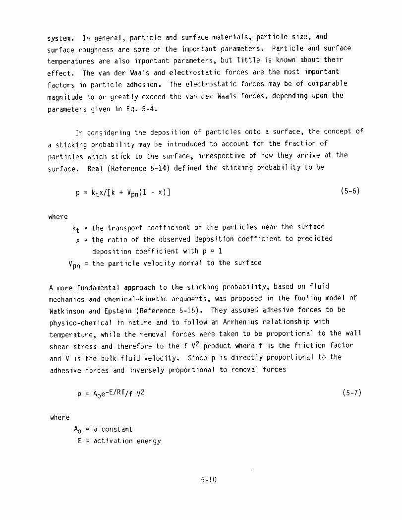
In considering the deposition of particles onto a surface, the concept of
a sticking probability may be introduced to account for the fraction of
particles which stick to the surface, irrespective of how they arrive at the
surface. Beal (Reference 5-14) defined the sticking probability to be
p = ktx/[k + Vpn(1 - x)] (5-6)
where
kt = the transport coefficient of the particles near the surfacex = the ratio of the observed deposition coefficient to predicted
deposition coefficient with p = 1
Vpn = the particle velocity normal to the surface
A more fundamental approach to the sticking probability, based on fluid
mechanics and chemical-kinetic arguments, was proposed in the fouling model of
Watkinson and Epstein (Reference 5-15). They assumed adhesive forces to be
physico-chemical in nature and to follow an Arrhenius relationship with
temperature, while the removal forces were taken to be proportional to the wall
shear stress and therefore to the f V2 product where f is the friction factor
and V is the bulk fluid velocity, Since p is directly proportional to the
adhesive forces and inversely proportional to removal forces
p = Aoe-E/RT/f V2 (5-7)
where
Ao = a constant
E = activation energy
5-10

Epstein (Reference5-1) has interpretedthe constantAo in terms of the
minimumfrictionvelocitywhich will inhibitthe depositionof particlesin
the first place. The phenomenaof adhesionof particlesis influencedby many
factors. As the fluid velocity increases,the stickingprobabilitydecreases
rapidly and as the particlediameter increasesthe stickingprobability
decreases. Also the force of adhesionof particleson a clean surface,or on
a surfacewith a layer of depositedparticles,influencesdepositionof
additionalparticles.
Beal has carriedout severalstudiesdealingwith particulatefouling
depositionmodels, and his major contributionswill be reviewedhere briefly.
In a classicalstudy, Beal (Reference5-16) proposeda model for predictingthe
depositionof particlesentrainedin a turbulentflow. His model was obtained
by integratingEq. 5-1, taking the Brownianor laminardiffusion,turbulent
diffusion,and inertialeffects intoconsideration. Thus, his model was
formulatedso as to be valid for particlesranging in size from very small
diameterto moderatelylarge particles,i.e., from molecularsize to 100um in
IO
i0o
uw
• I0 -Iu
zul
U
_. iO-ZI=Jo(.,)
Z9
_ 10_3w0
io-4
10-3 i0--_ i0-1 1(30 I0 I
PARTICLE DIAMETER, MICRONS
Figure 5-1. Effectof ParticleSize and Velocityon DepositionAccordingto Beal's Model (Reference5-16)
5-11

diameter. At small diameters molecular diffusion is controlling and at
large diameters the deposition is momentumcontrolled as shown in Figure 5-1.
The proposed model was compared with experimental data for particles ranging in
diameter from 10-3 um to 30 _m and velocities between 0.30 m/s and 61.0 m/s.
Good agreement with the experimental data was considered justification of the
model. In all cases the sticking probability was taken as being 1.0, i.e, all
the particles reaching the surface were assumed to stick to the surface. In a
later paper (Reference 5-14), based on an analysis of experimental particle
deposition data from the literature, Beal formulated a correlation for the
sticking probability in terms of the dimensionless stopping distance, S+. For
particles in air the sticking probability is 1 for small values of S+ and
inversely proportional to (S+) 3 for S+ > 4.5. In yet another study Beal
(Reference 5-17) developed a method for predicting agglomeration rates in
turbulent flow of suspensions. Whenever large numbers of particles are present
in a gas, they tend to collide with one another. If upon collision the
particles stick together the process is termed agglomeration or coagulation. In
a typical situation, the agglomertion rate exceeds the deposition rate for
particles smaller than 0o01 um, but the reverse is true for particles larger
than i0 um. In the intermediate range of 0.I to 1.0 _m, the rates are about
equal.
Several other deposition models have been formulated but have not been as
widely accepted as those discussed here. These studies include those of
Rouhiainen and Stachiewicz (Reference 5-18) who calculated particle trajectories
under the combined action of the Stokes drag force and a shear-induced lift
force. Sehmel (Reference 5-19) formulated a deposition model taking into
consideration turbulent diffusion, Brownian diffusion, and gravity settling.
His model predicted deposition for particle sizes of 10-3 to 102um and
particle densities of 1 and 10 gm/cm3.
5.3 CORROSION,CORROSIONFOULING, ANDCHEMICALREACTIONFOULINGMECHANISMS
The mechanisms related to corrosion, corrosion fouling, and chemical
reaction fouling are considered in this section. Since these phenomena are so
closely related, it seemed somewhat artificial to try and separate them; hence,
they have been grouped together under the same heading for discussion purposes.
5-12

Since most of the presentday cement kilns in the U.S. are using pulverized
coal as the fuel, with a continuingtrend in this direction,only those fouling
and corrosionmechanismsassociatedwith coal as a fuel will consideredhere.
Most of the informationin this sectionhas been taken from the coal-fired
boiler related literature.
BackgroundInformation
A knowledgeof the variousminerals found in coal is importantin trying
to understandthe variouschemicalreactionfouling and corrosionmechanisms.
Minerals in coal occur primarilyin four major groups: shale,clay, sulfur,
and carbonates. The ash is composed primarilyof Al203, SiO2, and Fe203
with trace amountsof CaO, MgO, K20, TiO2, P205, SO3, and Cl. (References
5-20 and 5-21). The specificcombinationof these elementsvaries by coal rank
and also dependson the metamorphesisof the coal. The presenceof the various
impuritiesin the coal, along with the ash chemistry,will be importantfactors
in those foulingand corrosionmechanismsrelatedto chemicalreaction
transformations.
In general,superheaterdepositsare formed as a result of the
interactionof dry flyash with condensablematerialusuallyappearingas
inherentmaterial in the coal. Sodium and potassiumgenerallyvolatilizein the
furnace and then condense out in the form of alkaliesand sulfates. Alkalies
released from low sulfur coals tend to condenseon the flyash,forming sticky
aluminosilicateswhich create sintereddeposits in the convectionportionof the
boiler. Alkalies releasedfrom high sulfur coal, on the other hand, tend to
form complex aluminumor iron alkali sulfateswith relativelylow melting
temperatures. It is clear that the distributionof impuritiesin the coal and
the ash chemistryof the coal are both importantparametersin chemica|reaction
related foulingand corrosionmechanisms. Some specificdetailswill now be
examined.
5-13

Alkali-Metal Deposition and Corrosion
One of the most important chemical reaction fouling mechanisms is that
resulting from alkali-metal sulfates. The presence of sulfur trioxide is a key
element in this fouling process which is generally believed to proceed as
follows (References 5-22, 5-23, and 5-24):
(1) Sodium and potassium are volatilized in part from the mineral matter
in the high-temperature flame forming Na20 and K20.
(2) During combustion, pyrites are dissociated thermally and, with the
organic sulfur in the coal, react with oxygen, forming mostly SO2
and some SO3.
(3) As the result of normal oxidation between 590 and 700 K, a thin
layer of oxide forms on the metal surface. The rate at which this
oxide layer grows decreases as the thickness increases, and a
more-or-less limited thickness is approached.
(4) The Na20 and K20 then react with S03, either in the gas stream
or on the tube surface, to form sodium or potassium sulfate,
Na2SO4 or K2S04, according to the reactions
Na20 + SO3 --> Na2SO4 (5-8)
K20 + SO3 --> K2SO4 (5-9)
These low-melting materials attract other particulates, eventually
building up a moderately thick deposit. During this process, SO3
is evolved as the result of reactions in the ash during the melting
process.
(5) The alkali sulfates, iron oxide, and SO3 then react to form the
complex sulfates, Na3Fe(S04) 3 or K3Fe(S04)3, which are
molten at about 865 K in a high-SO 3 environment ( ~i000 ppm).
5-14

The availabilityof SO3 is an importantpart of this mechanism. The presence
of iron oxide is necessaryfor the catalyticoxidationof SO2 to SO3
accordingto the reaction
SO2 + 1/202 --> SO3 (5-10)
Concentrationsof 0.11 percentsulfur trioxideare requiredprior to the
conversionof solid K2SO4 into liquidK2S207 at 755 K, while at 700 K
only 200 ppm SO3 are necessary(Reference5-25). Similarly,the possible
reaction of the alkali sulfateswith iron sulfatewas demonstratedby Corey
et al. (Reference5-23) to occur only when the SO3 concentrationswere greater
than 250 ppm
3K2S04+ Fe(S04)3 --> 2K3Fe(S04)3 (5-11)
3K2S04 + Fe203 + 3S03 --> 2K3Fe(S04)3 (5-12)
Similarreactionsmay be writtenfor sodium by replacingK with Na in Eqs. 5-11
and 5-12. Severalresearchers,includingClark and Childs (Reference5-26),
have pointedout the desirabilityof low excess air. The most generally
accepted explanationfor the beneficialeffectof low excess air is that there
is less free oxygen availablefor the transformationof SO2 to SO3
accordingto Eq. 5-10, Thus, reducing the amountof excess air will reduce the
amount of SO3 and under conditionswhen the concentrationof SO3 is less
than about 0.02 percent,corrosionwill not occur to any appreciableextent --
even in the presenceof alkali sulfates(Reference5-23). Also, corrosionwill
not occur in the absenceof alkali-metalsulfates.
Alkalineearths can inhibitthe formationof either potassiumor sodium
iron trisulfatewhich may be producedby either of the reactionsgiven in Eqs.
5-11 and 5-12. Calcium and magnesiumare known to have an inhibitingeffect on
the formationof potassiumor sodium iron trisulfatesby the formationof more
stable compounds. When sufficientconcentrationsof either CaO or MgO are
present, in either the coal ash or after calcinationof the sorbentmaterial,
5-15

reaction with gaseous sulfur trioxide will produce calcium or magnesium sulfate
according to the reactions
CaO + SO3 --> CaSO4 (5-13)
MgO+ SO3 --> MgSO4 (5-14)
These sulfates can, in turn, react with the alkali sulfates formed by Eqs. 5-8
and 5-9 to form an alkali calcium (or magnesium) trisulfate complex by the
reactions
2CaSO4 + K2SO4 --> K2Ca2(S04)3 (5-15)
2MgSO4 + K2SO4 --> K2Mg2(S04) 3 (5-16)
Reactions similar to Eqso 5-15 and 5-16 may be written for sodium by replacing
the symbol K in these equations by Na. The resulting calcium (or magnesium)
trisulfate is less corrosive than the alkali iron trisulfate phases. Field
experience, as well as that in a laboratory furnace, has also shown that most
coals treated with sufficient lime (CaO) to control the su|fur oxides produce a
softer, more friable deposit which is easier to control with soot blowers. The
calcium compounds produce a less dense, more bulky deposit than the equivalent
iron salt; therefore, the deposit is less tenacious and easier to remove.
Another possibility for reducing the fouling-corrosion potential is by reducing
the active alkali content of the coal, i.e., Na20 and K20.
Tufte and Beckering (Reference 5-27) investigated the mechanism of
chemical reaction fouling in lignite and found a similar phenomena as described
above in that sodium sulfate was deposited on the tubes. They speculated that
the basic deposition of Na2SO4 was due to vapor condensation, particle
diffusion, and eddy diffusion. The deposition of the flyash particles was
believed to be due to inertial impaction of the larger than average flyash
particles about the tube stagnation point. This argument has been proposed by
several investigators and substantiates the fact that the largest deposits
appear on the upstream side of the tube in the vicinity of the stagnation point
as shown in Figure 5-2.
5-16

LIQUID LIQUID(DUE TO HIGHHEATTRANSFERRATE)
CATHODI C
CORROSION" •_'.. •,._..;..'.... SOLID
"':.,:.::;DEPOSIT.._.,%t* : .o.
FLUEGAS
Figure 5-2. Schematic Illustration of Gas-Side Fouling Depositand Corrosion on Boiler Tube (Reference 5-7)
Tufte and Beckering also pointed out that Na2SO4 will be formed from SO3
in high sulfur streams and Na2CO3 in low sulfur streams. They suggested
that either species will act to flux deposits, but the sodium carbonate
deposition mechanism has not been investigated nearly to the extent which
Na2SO4 has. They suggested two possible ways to mitigate the sodium sulfate
type of fouling: (I) use an additive to tie up sodium in a non-reactive form to
inhibit its fluxing action, and (2) use an additive sprayed directly on the
pulverized coal that would eventually enter the ash and raise its fusion
temperature or otherwise inhibit the sodium fluxing action.
Hein (Reference 5-28) has carried out a preliminary study of gas-side
fouling in a coal-fired situation. Although not specifically related to
alkali-metal deposition and corrosion it is nevertheless of interest here. He
found that the deposition mechanisms can be influenced by excess air level,
burner-dependent mixing between fuel and combustion air, particle size
distribution of the coal, and combustion air temperature. Further research is
underway to quantify the effects of these parameters.
5-17

The Mechanismof Sodium SulfateDeposition
Brown (Reference5-29) experimentallystudiedthe rate of depositionof
sodium sulfatefrom combustiongases producedby burninga liquidfuel (sodium
naphthenateand carbondissulfideadded to kerosene)in a pilot-scalefurnace.
Depositswere producedon the outsideof circular-tubestainlesssteel specimens
exposedto the combustiongases at surfacetemperaturesof 695 K to 1015 K for
periodsup to 10 hours. Under conditionsof low excess air, which would
generallybe the case in cement kilns, sodium sulfate is formed by the chemical
reactions
Na20 + SO2 --> Na2SO3 (5-17)
Na2SO3 + 1/2 02 --> Na2SO4 (5-18)
Brown proposedthe followingexplanationfor the depositionof Na2SO4 onto
the tube surfacebased on his study. The theoretica!sodium sulfatedew-point
temperaturefor a gas.streamcarrying53 ppm Na2SO4 (his test conditions)is
1143 K. Thus, if the combustiongases are exposedto a surfacebelow the
dew-pointtemperature,the vapor condenseswithin the dew-point isothermwhich
is locatedatsome distancefrom the tube surface. The condenseddroplets are
then transportedtoward the tube surfaceunder the influenceof thermalforces.
(Sincethe particleswere believedto be about 0.1 um in diameter,the thermal
forces would undoubtedlybe due to thermophoresis). If the tube temperatureis
sufficientlylow, the dropletswill solidifybefore reachingthe surfaceand are
not likely to become attachedto the surface. However,as the tube temperature
increasesand approachesthe dew-pointtemperature,the depositionprocesswill
become dominatedby vapor diffusionand the depositionrate will increase.
Simultaneously,at temperaturesnear the dew-pointtemperature,the vapor
diffusionrate tends to decrease. Thus, as a consequenceof these opposing
trends,the depositionrate will pass througha maximum at a temperaturenear,
but somewhatbelow, the dew-pointtemperature. Thus, at surfacetemperatures
less than about 673 K (400C)and greaterthan 1073 K (800C),no depositionwas
5-18

observed in his experiments as shown in Figure 5-3. Between these temperature
levels, Na2SO4 was deposited on the tube surface with a maximum rate of
deposition in the vicinity of 875 K to 975 K. Although his study indicated a
Na2SO4 dew-point temperature of about 1073 K, this dew-point temperature in
general will vary depending on the concentration of the sodium
Figure 5-3. The Deposition Rate of Sodium Sulfate at 1.0 PercentExcess Air (Reference 5-29)
sulfate in the gas stream. Interestingly, he also found that while the
chemical reactions producing Na2SO4 are strongly dependent upon the amount
of excess air in the gas stream, the rate of deposition of Na2SO4 onto a
cooled surface is only weakly dependent upon the amount of excess air used in
the combustion process.
5-19
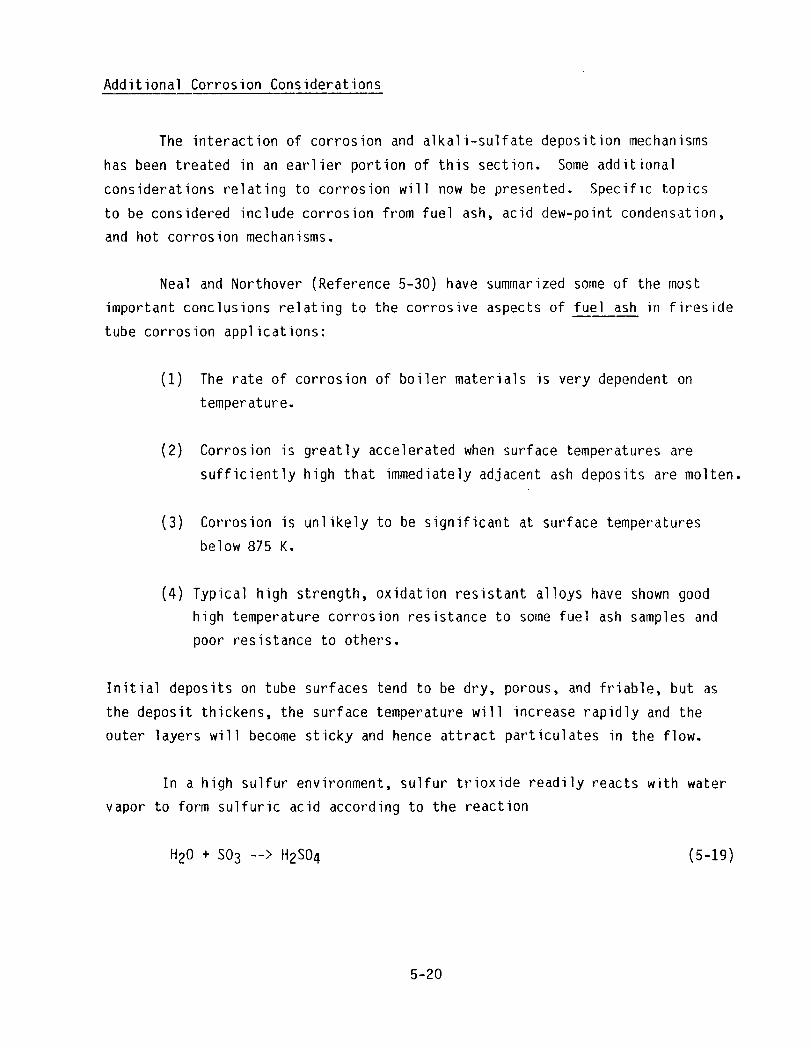
AdditionalCorrosionConsiderations
The interactionof corrosionand alkali-sulfatedepositionmechanisms
has been treated in an earlierportionof this section. Some additional
considerationsrelatingto corrosionwill now be presented. Specific topics
to be consideredincludecorrosionfrom fuel ash, acid dew-pointcondensation,
and hot corrosionmechanisms.
Neal and Northover(Reference5-30) have summarizedsome of the most
importantconclusionsrelatingto the corrosiveaspectsof fuel ash in fireside
tube corrosionapplications:
(1) The rate of corrosionof boilermaterials is very dependenton
temperature.
(2) Corrosion is greatly accelerated when surface temperatures are
sufficiently high that immediately adjacent ash deposits are molten.
(3) Corrosionis unlikely to be significantat surfacetemperatures
below 875 K.
(4) Typicalhigh strength,oxidationresistantal|oyshave shown good
high temperaturecorrosionresistanceto some fuel ash samplesand
poor resistanceto others.
Initialdepositson tube surfacestend to be dry, porous,and friable,but as
the dePOsitthickens,the surfacetemperaturewill increaserapidlyand the
outer layers will become sticky and hence attractparticulatesin the flow.
In a high sulfurenvironment,sulfurtrioxide readilyreactswith water
vapor to form sulfuricacid accordingto the reaction
H20 + SO3 --> H2SO4 (5-19)
5-20

At the cold end of the boiler,the H2SO4 can then condenseon the metal
surfacesand cause severe corrosionproblems. The wet wall can also attract
particulatesand cause plugging and foulingof the heat transfersurface.
Again, in additionto reducingthe H20 in the gases, the reductionof excess
air to preventthe formationof sulfur trioxideaccordingto Eq. 5-10 is a very
importantconsideration. Althoughvarioussurfacecoatingshave been proposed
to overcomethe acid dew-pointcondensationproblem,the present
state-of-the-artis just to avoid the problemby making sure that the exit gas
temperatureremainsa safe distance above the dew-point. Usually,this means
that the outlet gas temperatureshould be no less than about 450 K to 425 K.
There is also the possibilityof the formationof hydrochloricacid, HCI, in
situationswhere there is sufficientchlorinepresent in the exhaust gases.
Extensiveefforts are being conductedat Westinghouse(Reference5-25) to
predict the compositionof resultinggaseousand condensablecombustionproducts
in fluidizedbed combustionsystems. The formationof a liquid phase in the
deposit is usuallynecessaryfor corrosionto occur at an appreciablerate as
discussed in the precedingparagraph. Although a generalizedhot corrosion
mechanismhas not yet been delineated,it appearsthat one or more of the
followingdetrimentaleffectsmay be occurringsimultaneously:
(1) Removalof protectiveoxides on the metal surfacethroughchemical
reactionof corrodantsformed within an overlyingdeposit.
(2) Reactionsof the protectivescale with constituentsin the flue gas
and the overlyingdeposit.
(3) Direct attack of the metal surface.
MgO Additives
The beneficialeffectsof CaO and MgO in mitigatinggas-sidefoulingwere
brieflyconsideredearlier in this section. The purposeof the present section
is to consider in greaterdetail the importantrole which magnesiumoxide plays
in this process. Of all the possibleadditives,MgO has probablyreceived the
5-21

greatest attentionto date as a possiblecompoundto minimize the effectsof
gas-sidefouling in heat recovery applications.
In the early 1960s magnesiumoxide,MgO, was used successfullyto
minimizegas-sidefouling in coal-firedboilers, However,the dosages at that
time required0,4 to 3,0 percentof the fuel burnedwhich were not economical,
However,Radway and Boyce (Reference5-31) have recentlyreportedvery positive
gas-sidefoulingreductionsat very low MgO treatmentrates of 0,015 percentor
less. In one phase of the study, treatmentrates from 150 to 1250 ppm of MgO
were utilizedwith a temperature-controlleddepositionprobe at 773 - 883 K to
simulateconditionsfound in modern utilityboilers, The depositsformed on
the probe were friable,more powdery, and more easily removedwhen dispersed
MgO was being used, In a second phase of the study the sulfuricacid
depositionrate at 386 K surfacetemperatureshowedthe reductionin acid
depositionr_ateto be directly proportionalto the MgO treatmentlevel,
Deposit analysis,X-raydiffraction,and differentialthermal analysiswere
used to analyzethe results. Although the basic mechanismswere not
establishedwith certainty, it is believedthat the gas-phasereactionbetween
MgO and SO3 results in the formationof MgSO4 accordingto the reaction
MgO + SO3 --> MgSO4 (5-20)
which is a very stable compoundresulting in dry and very friabledeposits. In
addition,the reactionof sulfur trioxidewith the magnesiumoxide would leave
less SO3 to react with water to form sulfuric acid
H20 + SO3 --> H2SO4 (5-21)
The reducedformationof H2SO4 with increasingMgO would thus explainthe
reductionin acid depositionwith increasingMgO. Two key featuresof the
tests were:
(1) Extremelysmall MgO particlesize. (The finer the size, the greater
the surfacearea of MgO particlesper unit mass).
(2) Separate injectionof the MgO and fuel so that the chemical loss of
MgO with the bottom ash is minimized.
5-22

It is interestingto note that MgO is a naturallyoccurringconstituentin
the feed material in cement kilns. Thus, it is possiblethat in those
situationswhere sufficientquantitiesof MgO are presentin the raw materials,
a naturallyoccurringadditiveis presentin the feed.
5.4 REMOVAL MECHANISMSAND MODELS
Many terms have been used to describethe removal processincluding
re-entrainment,detachment,sloughingoff, release,scouring,spaIling,and
erosion. Although all of these terms have been used in the literature,the
terminologyremovaland re-entrainmentwill be used here to describethe natural
movement of a portionof the fouled layer from the heat transfersurface, i.e.,
natural in the absenceof externalforces such as those producedby soot
blowers. The purposeof this section is to review the mechanicsof the removal
process in gas-sidefouling,and to considerbriefly some of the removalmodels
which have been proposed. Removal phenomenahave not been studiedas
extensivelyas depositionmechanisms;consequently,the removal process is not
as well understoodas that of deposition.
Kern and Seaton (Reference5-32) postulatedthat the time rate of change
of the foulingresistanceshouldbe of the form
dRf/dt = @d - @r (5-22)
where
@d = the depositionrate
_r = the removalrate
Rf = fouling resistance
t = time
Furthermore,Kern and Seaton were apparentlythe first to recognizethe
importanceof the shear stress in the removalprocess. They assumed@d
to be a constant,@r to be proportionalto Rf, and then integratedEq. 5-22
to obtain
Rf = R_[1 - e -At] (5-23)
5-23

where
R_ = asymptotic fouling resistance
A = a constant
A plot of Eqo 5-23 is shown in Figure 5-4 and indicates that the fouling
resistance Rf asymptotically approaches the value R_ as t approaches
infinity. However, in many practical situations the behavior shown in
Figure 5-4 is not achieved because the assumptions underlying the derivation
of Eq. 5-22 are not satisfied.
Taborek et alo (References 5-33 and 5-34) extended the work of Kern and
Seaton and suggested that the removal function @r should be
@r = BoTw Rf/ _ (5-24)
where
B : a constanto
= deposit strength
Rf
c-"
u')
* At]= [I - e-.r--
,-go
I.L
Time, t
Figure 5-4. The Kern-Seaton Fouling Model Illustrating the AsymptoticFouling Resistance Behavior (Reference 5-32)
5-24

Thus, they indicatedthat the removalfunctionshouldbe directlyproportional
to the wall shear stress and the foulingresistanceand inverselyproportional
to the depositstrength. Since the frictionfactormay be interpretedas the
dimensionlessshear stress,the removalfunctionmay be alternatively
interpretedas being directlyproportionalto the frictionfactorand the square
of fluid velocity. Althoughthe depositbegins to age as soon as it has been
depositedon the surface,removalof the depositmay or may not begin as soon as
depositionhas been initiated. The scale strength_ in the Taboreket al. model
is a measure of the resistanceof the depositto removalor re- entrainment.
The aging processmay includechanges in the chemicalstructureof the deposit,
and it may also be affectedby the surfacetemperaturein some applications.
Althoughthere are exceptions,the deposit in generalbecomesmore tenacious
with time and hence becomesmore difficultto remove,eitherby natural
re-entrainmentor by externaltechniquessuch as soot blowers. For example,
depositscan sometimesbe removedby heatingthe surfaceto a sufficientlyhigh
temperaturesuch that the deposit strengthis weakenedto the extent that the
fluid shear forces are adequateto removethe deposit. Since the removal
process is directly proportionalto the frictionfactor, it would appearthat
rough depositswould have a greaterremovaltendencythan smoothdeposits. In
any case, experimentalwork has clearlyshown that re-entrainmentwill not occur
under laminarflow conditions. In other words, in order to have removalof the
fouled layer,the mainstreamflow must be turbulent.
Severalexperimentalstudieshave shown that the laminarsublayer in the
turbulentboundary layer is not truly laminarbut, in fact, is unsteadyand is
continuallydisruptedby what Cleaverand Yates (Reference5-35) have termed
"turbulentbursts." These bursts are like miniaturetornadoesand can cause
instantaneouslift forces which are largeenough to detach particleswhich have
been depositedonto a surface. Cleaverand Yates have proposedthe following
criterionas a conditionfor re-entrainment
Tw dp _ constant (5-25)
Althoughthe mechanismof removal is not clearlyestablishedin their paper,
this criteriondoes show generalagreementwith previousexperimentalstudies.
However,since their model does not includeany referenceto deposit strength,
it is clear that Eq. 5-25 has limitedapplicability.
5-25

A final type of removal mechanism which may be of importance in
cement plant applications is known as "splashing." Bagnold (Reference 5-36)
observed splashing of particles when a traveling particle impacted a
non-sticking layer of previously deposited particles. Semanand Penny
(Reference 5-37) noted that particles striking a layer of electrostatically
deposited dust caused splashing and re-entrainment. Splashing is produced
mainly by particles larger than those in the deposited layer. In general, it
would be expected that the momentumof the impacting particles, i.e., both the
mass and the velocity, would be an important parameter in removal by a splashing
type mechanism. As part of a study Concerned primarily with sticking
probability, Beal considered the erosion of previously deposited particles
(Reference 5-14). Based on two previously published sets of data, he found the
erosion coefficient to be proportional to the drag force raised to the 0.88
power.
5.5 EROSION
Erosion carl be a serious problem in particulate-laden flows and depends
on the size distribution of the particles, the surface material, the temperature
of the solid surface, the velocity of the particles, the velocity of the fluid,
the properties of the particles, and the geometry involved. Hansen et al.
(Reference 5-38) have reviewed the importance of various erosion parameters.
The impingement angle for maximumerosion of ductile materials such as the
commonly used steels ranges from about 20° to 45° with most investigators
indicating 30° as a representative value. Erosion increases with both the
particle velocity and particle size. At low concentrations, such as would be
found in cement plants, erosion increases with particle flux. Interestingly, at
high concentrations the effects of erosion tend to decrease because the
particles impact each other. Sharp particles produce more erosion than smooth
ones, but particle hardness -- provided the particles are harder than the
surface material -- apparently has little or no effect. Finally, Hansen et al.
have indicated that there are no material properties which can reliably
correlate erosion resistance.
5-26

Kotwal and Tabakoff (Reference 5-39) in a recent study found that erosion due to
fly ash is caused primarily by silica and alumina, SiO2 and A1203, both of
which are present in cement kiln dusts. In coal-fired kilns, these
particulates come from the ash in the fuel as well as from the feed itself.
Kotwal and Tabakoff used 304 stainless steel and found that erosion: (I) is a
maximum at an impingement angle of about 30° , (2) increases with both particle
velocity and diameter, and (3) increases as surface temperature increases. The
fly ash used in their tests had particulates which ranged in diameter from I um
to 100 _m, which essentially is the same range encountered in cement kiln and
clinker dusts. Soo (Reference 5-10) has reported that erosion decreases as the
gas pressure increases, but this observation is of little importance in cement
plant applications where gas pressures are only slightly above atmospheric. In
cement plant applications, the greatest potential for erosion occurs in the
clinker cooler exhausts where the gases tend to be highly abrasive because of
the particulates from the clinker.
5-27


SECTION6
GAS-SIDEFOULINGEXPERIENCEIN CEMENTPLANTS
Heat-transferequipmentused in the cement industrywas describedin
Section4. Gas-side foulingmechanisms,as they are believedto relate to the
cement industry,were discussedin Section5. Gas-sidefoulingexperiencein
cement plants is documented in this section. The specifictypes of heat
exchangersconsideredare the same as in Section4 with the exceptionof
clinkercoolerswhich, becauseof their design and function,are not subjectto
gas-sidefouling. Gas-side foulingmechanismsof interesthere include
particulate,chemicalreaction,and corrosionfoulingalong with the related
topics of corrosionand erosion.
6.1 PREHEATERS
Reference3-8 is an excellentpaper dealingwith field and laboratory
experiencewith buildups in cement plants. Buildup is defined as an
undesirablecoatingor accretionthat can form in a kiln, preheater,or other
parts of a kiln system. Thus, in contrast to fouling,buildupscan occur on
other than heat transfersurfaces, However,much of the informationin this
very importantpaper is of interesthere, especiallythat relatingto
preheaters. Since such buildupsoccur on the surfacesof the cyclone
separators,and not on heat-transfersurfacesper se, it might be argued that
such depositsdo not constitutefouling in the sense in which it is defined in
this report. However,such buildupson suspensionpreheatersurfacescan and
do affect the direct contactheat transferprocesseswithin the preheater.
In addition,the alkali sulfatesand chloridesfrom the hot exhaust
gases can condensedirectlyonto the cool raw feed particulatesin the
preheater. This process increasesthe level of contaminantsin the kiln gases,
which in turn can contributeto gas-side foulingproblemselsewherein the
system. Therefore,for these reasonsbuildups in preheaterswill be given
appropriateconsiderationhere. In four-stagepreheatersthe tendencyfor
buildups is least in the first stage and the greatest in the fourth or
6-1
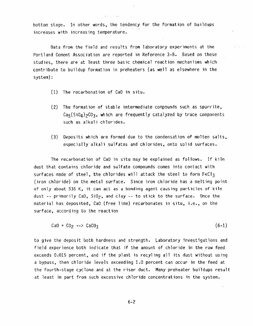
bottom stage. In other words, the tendency for the formation of buildups
increases with increasing temperature.
Data from the field and results from laboratory experiments at the
Portland Cement Association are reported in Reference 3-8. Based on these
studies, there are at least three basic chemical reaction mechanisms which
contribute to buildup formation in preheaters (as well as elsewhere in the
system):
(1) The recarbonation of CaO in situ.
(2) The formationof Stable intermediatecompoundssuch as spurrite,
Ca5(Si04)2C03,which are frequentlycatalyzedby trace components
such as alkalichlorides.
(3) Deposits which are formed due to the condensation of molten salts,
especially alkali sulfates and chlorides, onto solid surfaces.
The recarbonation of CaO in situ may be explained as follows. If kiln
dust that contains chloride and sulfate compounds comes into contact with
surfaces made of steel, the chlorides will attack the steel to form FeCl 3
(iron chloride) on the metal surface. Since iron chloride has a melting point
of only about 535 K, it can act as a bonding agent causing particles of kiln
dust -- primarily CaO, SiO2, and clay -- to stick to the surface. Once the
material has deposited, CaO(free lime) recarbonates in situ, i.e., on the
surface, according to the reaction
CaO+ CO2 --> CaCO3 (6-1)
to give the deposit both hardness and strength. Laboratory investigations and
field experience both indicate that if the amount Of chloride in the raw feed
exceeds0.015 percent,and if the plant is recylingall its dust without using
a bypass,then chloride levelsexceeding1.0 percentcan occur in the feed at
the fourth-stagecyclone and at the riser duct. Many preheaterbuildups result
at least in part from such excessivechlorideconcentrationsin the system.
6-2

ChemicalanalysesFrom fourth-stagebuildups in two differentplants,
designatedas Plants A and B, were carriedout. Both plants were using a raw
feed containing0,045 _ 0,005 percentchloride and 0.050 _ 0.010 percent
fluoride. All of the kiln dust was returnedwith the feed in both plants. The
analyses indicatedthat the fourth-stagebuildupin Plant A consistedprimarily
of the compoundsKCI, spurrite,and NaCl, with smallerquantitiesof CaCO3,
C12A7, and CaSO4. The buildup in Plant B consistedprimarilyof CaO,
CaCO3, and spurriteplus smallerquantitiesof SiO2, C12A7, KCI, C2S,
CaSO4, and calcium langbeinite. The temperatureof the gas leavinga fourth
stage is usuallyabout 1075 K, and the gas temperatureenteringthe cyclone is
typicallyabove 1275 K. These temperaturesspan the range over which alkali
chloridevapors condenseto the liquidstate. Therefore,under these
conditions it is reasonableto expect chloridecondensationin the fourth stage
of the preheater. Laboratoryexperimentsshowed that the alkalichlorides,KCI
and NaCl, are very effectivecatalystsin the formationof spurrite. Tests on
the Plant A buildupsuggestedthat it containedmore spurritethan Plant B
buildupbecause it was much richer in alkalichlorides. Subsequenttests with
the kiln dusts given in Table 3-6 confirmedthat spurriteformed only from Dust
L which contained6,24 percent chloride,compared to all the other dusts which
contained less than one percentCl. Laboratorytests also showed that a
temperatureof about 1075 K, which is the temperaturein the fourth stage of
the preheater,is required for this reactionto take place. It is believed
that the CaCO3 (calcite)buildup in Plant A was due to the recarbonationof
CaO in situ. The anhydrite, CaSO4, was probably formed as a result of a
reaction between CaOor CaCO3 from the raw feed and SO2 from the kiln gases.
Buildups in the kiln formed at the feed end of the kiln are very similar
to those formed in the fourth stage of the preheater. On the other"hand,
buildupsnear the kiln exit have a compositionvery similarto that of the
clinker. Bhatty (Reference3-8) has reported the analysisof one kiln buildup
near the feed end of the kiln. This particularbuildupcontainedprimarily
spurrite (more than 55 percentby weight)and a|so a large _nount of sulfate
spurrite (calciumsilicosulfate). It containedonly a small amount of CaCO3,
indicatingthat most of the CaO had combinedwith SiO2 and sulfur to produce
the large quantitiesof the two types of spurrite. The depositalso contained
smal] amountsof CaSO4, calcium langbeinite,K2SO4, and KCI. Buildups formed
6-3

at the exit of the kiln are not of particularinteresthere because, strictly
speaking,the processestaking place withinthe kiln do not fall under the
domain of heat recovery. However, Bhatty has presentedsome importantresults
on the buildupformed on dolomitebrick in the burningzone of a kiln, Of
particularinterest here is the buildupwhich occurred nearestthe refractory
lining. This inner layer containedabout 20 percent alkali sulfate,primarily
K2SO4, It was speculatedthat the depositionof the alkali sulfate in the
pores of the dolomite brick could have initiatedformationof the deposit.
Initiallythe vapor could have penetratedthe cores of the brick, condensingto
a liquidor a solid on the outer surfacesnear the kiln she|l.
Bhatty summarizedhis findingsby suggestingseveralsteps which could
be taken to eliminateor reduce the buildupproblemswhich were observed.
First, the use of materials in the raw feed which containexcessivequantities
of chloride or sulfur compoundsshould be reducedor eliminated. Second, if
possible,the use of high sulfur coal should be avoided. Third, calcium
chloride,CaCl2, should not be used to preventthe freezingof coal in the
winter in cold climates. Fourth, in Preheatersystemsa kiln bypass system
should be used to limit the levelsof chlorides,alkalies,and sulfur in the
kiln. Fifth,the use of coals with high ash content and low ash fusion
temperaturesshouldbe avoided. Sixth, the kiln and preheaterconditions--
such as temperature,pressure,feed rate, etc. -- shouldbe monitored in order
to detect the formationof buildupsduring their early stages. Finally,
excessivecoolingof the kiln shell should be avoided; infact, in some cases
buildupscan be dislodgedby insulatingthe kiln shell where the builduphasformed.
Strict controlof the constituentsin the raw feed and the coal,
includingthe ash, is somewhatdifficultbecauseof the variation in both of
these quantities. The kiln bypass in the preheatersystemshas proved to be a
very effectiveway to eliminatechlorides,sulfates,and alka|ies as was
discussedearlier. The possiblemonitoringof the kiln and preheatersurface
temperaturesdeserves some furtherconsideration. In fact, Coplay Cement of
Nazareth,Pennsylvania,has installedan infraredscanningsystem to
continuouslymonitor the she|l temperatureof rotary kilns. An AGA Cemscanner
continuouslymonitors the kiln skel], which is 85.3 m long and 5.49 m wide, on
6-4

a 24 hr, seven days a week basis. When the detectorregistersa sharp increase
in temperature,indicatingthat a coatinghas droppedoff the kiln wail,
high-poweredfans are used to cool the shell in order to promotethe buildingof
a new coatingto preventpossiblefurtherbrick damage. A similarprocedure
could be used to detect buildups,by noting a drop in surfacetemperature,in
the kiln and also in the preheater. Thus, costly unscheduledshutdowns,along
with the loss of production,could be avoidedor at least minimized. (Reference
6-1).
Chistyakovaand Mi]haylov(Reference6-2) have reportedchemical
analysesof severalAeposit samplestaken from a preheatersystem. The kilns
were fired with a mixture of coal and gas shale and the raw material included
fine coke, a waste productfrom the gas-shaleindustry. The regionof maximum
foulingoccurred in the zone betweenthe upper end of the kiln and the
first-stagecyclone. In general,the analysesshowed -- in comparisonto the
raw feed -- that the depositswere rich in alkalies,sulfates,and chlorides.
Although the discussionsin Reference6-2 are quite brief, and somewhatsketchy
in places,some generalresultswere obtainedwhich are of interesthere. In
the sample analyseswhich were carriedout, it was found that ingeneral the
deposits were basicallyof multicomponentcharacterand that they contained
primarilythe followingconstituents: K2S04, KCI, K2Ca2(S04)3,CaSO4,
C2S, CaO, CaCO3, and C3A. Smallerquantitiesof sodium sulfatesand
chlorideswere also present,along with an iron-containingphase. Specifically,
one depositcontainedmore than 40 percentK2Ca2(S04)3,and a seconddeposit
consistedof up to 50 percentK2SO4. Chistyakovaand Milhaylovconcludedas a
result of their findings,that a reduction in the amounts of alkalichlorides
and sulfates in the feed and in the fuel could overcomethis problemof fouling.
They also suggesteda modificationin the design of the heat exchangersin order
to reduce the processof coatingformations,but did not give any specific
details.
Apparently,based on operationsin Europe, the counterflowpreheater
described in Section4-1 has experiencedno downtime as a result of buildup
problems. (References6-3 and 6-4). The manufacturersclaim that this type of
preheateris not subjectto foulingdepositsbecauseof the large cross-
sectionalareas of the tube in which any incipientbuildupsfall off as a
6-5

result of their own weight before the deposit has a chance to age and become
tenacious. They also claim that because of the specific design of the
preheater, the sticky particles become entrained by the kiln gases and hence do
not deposit on the walls of the preheater. However, in spite of the successful
operating experience of the counterflow preheater in European applications, a
critical evaluation of the performance of this type of preheater in high alkali
feeds, such as found in certain parts of the U.S., is not available.
6.2 GAS-TO-AIR HEATEXCHANGERSp
Smith Engineering Company has built 32 gas-to-air units which are
presently in operation in clinker cooler vent line exhausts throughout the
United States. The volumetric flowrates for these units range from a low of
5.66 m3/s to a maximumof 59.5 m3/s. Except for some erosion and flow
maldistribution problems, caused by poor header design in one case and flow at
an angle to the tubes in another case, these units have operated very
successfully. There is no evidence of any fouling problems in these units,
probably because the clinker dust is very abrasive and tends to clean the
inside of the tubes as the exhaust gases flow through the tubes. The
replaceable sleeves described in Section 4 adequately handle erosion problems
near the inlet of the tubes.
Smith Engineering has one gas-to-air unit installed in the bypass loop
of a suspension preheater system. This exchanger is located at the Cementos
Mexicanos plant near Mexico City, Mexico. The gases leave the preheater at a
temperature of about 1255 K and are quenched with cool air to a temperature of
755K. Thus, the inlet gases to the heat exchanger have a temperature of about
755 K and are cooled in the exchanger to about 535 K before entering a
baghouse. Even though the gases are heavily laden with alkalies, there has
been no evidence of any fouling inside the tubes. Probably the reason no
difficulties have been encountered is because the maximumgas temperature of
755 K is below the temperature range of 865-920 K at which the alkalies become
sticky. This unit has apparently not been operated in the 865-920 K
temperature range, either accidentally or intentionally.
6-6
A very interestingproblemhas been encounteredin a heat exchanger
operatingat the MonarchCement Company,Humboldt,Kansas, The gas-to-air
unit,manufacturedby Smith EngineeringCompany,was installedin the downcomer
betweenthe suspensionpreheaterexit and the induceddraft vent fan, The
purposeof this exchangeris to cool the preheaterexhaustgases, thus reducing
the amountof bleed air required, This exchangerhas 0.0762m diametertubes,
6.71 m tubelength,and 616 tubes arrangedon an inlinelayout. The unit is
rated at about 5280 kW with a volumetricflowrateof 19,6m3/s. The exhaust
gases enter the top of the exchangerand flow verticallydownward insidethe
tubes. Operationof the exchangerresulted in the buildupof a 3.18 mm-thick
deposit in a very short periodof time. However,after reachingthis
thickness,the depositessentiallyremainedat this thickness,i.e,, a
conditionof asymptoticfoulingwas reached. This insulatinglayer reducedthe
heat transferby a factor of about two, and increasedthe pressuredrop by a
factor of about three, Four vibrators(ESP rappers)and a sonic horn were
installedin an attemptto remove the depositwithoutsuccess. At one point it
was thoughtthat the formationof sticky CaSO4 salts was a contributing
factor, However,very detailedchemicalanalysesled to the conclusionthat
there was no evidenceof any chemicalreactionor that the physicalor chemical
characteristicsof the dust were responsiblefor the buildup. Measurements
indicatedthat the dust was very fine with over 25 percentof the dust
particlesless than 2.1um in diameterand over 50 percentof the dust less
than 4,2 _m in diameter, Owing to the 3.18mm-thick buildup,and the
associatedoperatingproblems,the heat exchangerwas taken offstremnand was
allowedto sit idle for about 9 months. Sometimeduring this nine-month
period, it was later discoveredthat the depositdroppedoff the tubes and fell
to the bottom of the exchanger,When the exchangerwas put back in service it
fouled just as before in a matter of a few hours. Thus, based on the chemical
and physicalanalyseswhich were carriedout, it is believedthat static
electricityis the basic depositionmechanismin this particularproblem
(Reference6-5). However,since over 50 percentof the depositedparticles
were less than 5 _m in diameter,it is also possiblethat thermophoresiscould
have been a contributingtransportmechanismin this case. However,a more
detailedstudy of this phenomenonwould be required to determinewith greater
certaintywhetherthe depositionmechanismwas indeedone of combined
electrophoresisand thermophoresis.
6-7

Another Smith Engineering gas-to-air heat exchanger was installed at the
Kaiser Cement and GypsumCorporation plant in Permanente, California. It was
installed such that the preheater exhaust gases could be: (I) routed directly
to the heat exchanger for cooling prior to entering a dust collector, or
(2) used to preheat the material in the grinding mill when the raw mill was
operating. In the latter mode, the exhaust gases passed successively through
the raw mill, a cyclone separator to remove particulates, an induced draft fan,
and then to the heat exchanger, after which the gases went to the dust
collector. In this loop the exhaust gases normally entered the heat exchanger
at a temperature of about 395 K and left at about 320 K. However, since the
gases had a considerable amount of moisture in them, water condensed onto the
cool tube surfaces which attracted kiln dust, and the tubes became plugged very
quickly. Unfortunately, this particular system did not include a bypass loop
around the heat exchanger which could have been utilized at appropriate times
to alleviate this problem.
At the Martin Marietta Cement plant in Davenport, lowa -- which went
onstream in December 1981 -- a gas-to-air heat exchanger is operating in the
preheater exhaust str6am. This particular unit has 0.102 m diameter tubes and
was manufactured by American Air Filter Company, Inc., Louisville, Kentucky.
There has been some plugging of the tubes in this exchanger which is known to
be operating in a situation with high levels of both SO2, resulting from the
sulfur in the coal, and moisture so it is likely that CaSO4 is being formed
in the exhaust gas stream. Also, there has been some evidence of mild
corrosion of the tubes, but no pitting has been observed. Presently, the
gas-side fouling problem is being handled by the use of sonic soot blowers,
activated about every 15 minutes on a continual basis (Reference 6-6).
A gas-to-air heat exchanger in a preheater exhaust application has
recently been installed at the California Portland Cement plant in Mojave,
California. This exchanger, which has 0.0762 m diameter plain tubes 9.14 m
long, was manufactured by Tera Engineering Company, Santa Fe Springs,
California. It is known that the exhaust gases in this installation contain
SO2 and large amounts of water vapor. Although random plugging of a few
tubes has occurred to date, the problem is not serious and the heat exchanger
is operating successfully (Reference 6-7). This particular exchanger has the
6-8

uniquefeaturethat a portionof the hot exhaust air is recycled and mixed with
ambientair so that the air temperatureentering the unit is about 340 K,
rather than at ambientconditions. A very large surface area of 4460 m2 has
been incorporatedinto the exchangerto ensure that the desiredoutlet gas
temperatureis achieved. The elevated-inlet-air-temperaturedesign ensures a
sufficientlyhigh insidetubewalltemperaturethroughoutthe heat exchangerso
that the acid and water"dewpointproblemis avoided (Reference6-8).
6.3 WASTEHEATBOILERS
The RiversideCement Company,recentlypurchasedby the Gifford-Hill
Company,has been generatingelectricalpower for over 25 years using waste
heat boilers(References6-9 and 6-10). Based on this successfuloperating
history,the decision was made to converttwo, two-stagepreheaterkilns to
waste heat boiler systemsto generateelectricity. The boilers are rated at
955 K and 4.83 MPa and were suppliedby the Deltak Corporation,Minneapolis,
Minnesota. Each boiler was also equippedwith an economizerand a superheater.
In the superheatersection,which is of principalinteresthere, the tubes are
0.0508m diameter,the transversepitch is 0.127 m, and the longitudinalpitch
is 0.152 m with an inlinelayout. On initialoperationof the system,the gas
passages in the superheatersectionof the boiler became pluggedwith a hard,
glass-likedeposit in a matter of just a few days. The heaviestdepositwas in
the first three rows and resembledthat shown in Figure 5-2. In order to clean
the heat exchangersurfaces,the material was chiseled out manually. At the
same time, the gas temperatureenteringthe superheaterwas about 1060 K.
Experiencewith the existingwaste heat boilershad demonstratedthat a gas
temperaturemuch above980 K would cause pluggingof the boilers. It is
believedthat the mechanismcausing this particulartype of fouling is
condensationor de-sublimationof potassiumsulfateand sodium sulfate,
processeswhich occur about 1045 + 6 K (Reference6-11). Althoughboth systems
were initiallyequippedwith rotary sort blowers, they were removed after one
of them turned out to be defective. An attemptwas then made to install
additionalchains in the kilns to bring the gas temperaturedown to the 950 K
design value. However,this approachwas apparentlynot entirelysuccessful;
therefore,at the presenttime an evaporativegas cooling systemmanufactured
by Sonic DevelopmentCorporation,Mahwah, New Jersey, is being installedjust
6-9

upstreamof the superheatersection. This systemwil! maintain the gas
temperatureat a level below the sulfatede-sublimationtemperatureby
modulatingthe degreeof superheatin the economizers(Reference6-11).
The gas-sidefoulingmechanismin this particularcase appearsto be
very similarto the sodium sulfatedepositionmechanismreported in Reference
5-29 and describedin Section5.3. It will be recalled in that study that at
1045 K (772 C), the Na2SO4 depositionrate was close to a maximumvalue.
Thus, it would be expectedthat a drop in the gas temperaturewould reduce the
wall temperatureand hence the depositionof the alkali sulfatesas shown in
Figure5-3. Thus, the proposedevaporativegas coolingsystem shouldeliminate
or at least reduce the gas-sidefoulingproblemswhich have been experiencedat
the RiversideCement Company.
The St. LawrenceCement Company,with supportfrom the Canada Energy,
Mines and Resources,has recentlyundertakena projectto achievemajor energy
savings in their cement plant at Mississauga,Ontario,Canada (Reference2-3).
One phase of this projectinvolveswaste heat utilizationto generate
electricity. The waste gas stream utilizedwas the preheaterexhaustwhich was
laden with dust to the extent of 20-30 gNm-3. It was anticipatedthat
these gases could cause erosion and/orfoulingof heat exchangersurfaces;
therefore,a preliminarystudy was carriedout to investigatethe potential
problems. A small-scaleheat exchangerwas constructedwith six carbon steel
tubes: two plain tubes, two externallyfinnedtubes with 78.7 fins/m and two
externallyfinned tubes with 157 fins/m. The dimensionsof the tubes were not
given in the report. The tubes were mounted in a crossflowarrangementwith
the dirty gas flowingon the outside of the tubes and cool air on the insideof
the tubes.The tubes were individuallyinstrumentedto measurethe inlet and
outlet air temperatures,insidewall temperature,and exhaustgas temperature.
Thus, the temperaturemeasurementswere used to monitorthe effectsof gas-side
fouling. The kiln was in continuousoperationfor a month, and during this
time temperaturemeasurementswere taken at regular intervals. Gas
temperaturesranged from about 570 to 630 K, with correspondingaveragewall
temperaturesof about 355 to 520 K. Based on these measurements,it was
determinedthat the effect of foulingwas negligibleon all the tubes during
the entire course of the study. Interestingly,the tubes were coveredwith a
6-10

fairly thick layer of dust upon completionof the tests. However,it was
discoveredthat this dust was very looselydepositedand could easily be
removed by either blowingair over the tubes or by vibratingthem slightly.
Thus, it was concludedthat this materialcould not have been on the tubes
during the tests and undoubtedlywas depositedas the tubes were cooled during
the shutdownoperations. A visual inspectionof the tubes indicatedthat no
significantcorrosionor erosionproblemshad occurredduring the month-long
study.
The NationalGypsum Companyplant in Alpena,Michigan,generates
electricityusing plain-tubewaste heat boilers. Nine long-dryprocesskilns,
fired using coal as the fuel, are currentlyin operationat this site. The use
of waste heat boilers at this plant is due in part to the kerogencontentof
the local shale which is used as one of the raw materials. NationalGypsum has
a cogenerationagreementwith the local electricutilitywhich allows them to
sell electricitywhich is produced in excess of the requirementsin the cement
plant. Althoughsome gas-sidefoulingproblemshave been experiencedin the
past at this plant, steam soot blowersare presentlybeing used on a regular
basis with no gas-sidefoulingproblems.
6-11


SECTION7
DELETERIOUSEFFECTSOF GAS-SIDEFOULINGIN CEMENT PLANTS
There have been very few attemptsto quantifythe deleterious
effectsof any type of fouling. The major problemis the number of
uncertaintiesinvolvedin such an analysis. As Thackery (Reference7-1) has
pointedout, such effortsbasicallybecome a seriesof "consideredguesses"
becauseof the many unknowns. However,Reference7-1 is undoubtedlythe best
and most comprehensivecontributionin this area, Thackery'sanalysis includes
the cost of all types of fouling in the United Kingdom and attachesan
estimatedcost in Britishpoundsto each of the associatedcosts. The purpose
of this sectionis to consider the deleteriouseffectsof gas-sidefouling in
U,S, cement plants, includingcorrosionand erosion,and to estimatethe
relatedcosts in presentU.S. dollars.
The deleteriouseffectsof foulingin cement plantsmay be broken dcwn
into the followingcategories:
(1) Increasedcapitalcosts.
(2) Increasedmaintenancecosts.
(3) Loss of production.
(4) Energy losses.
Each of these items wil| be consideredin more detail.
Increasedcapitalcosts result in part from oversizingequipnentto
accountfor the anticipatedfouling. First, the fouling layer producesa
thermal resistancebecauseof its relativelylow thermalconductivity. This
resistance,in turn, requires a larger"surfacearea for a given heat transfer
requirement. Gas-sidefoulingfactorsare not well known at the presenttime,
so excessivelylarge safety factorscan result in very conservativedesigns.
Second,becauseof reducedflow passagesdue to the foulinglayer, an increased
pressuredrop is produced, Therefore,capitalexpendituresare requiredfor
larger fans becauseof the largerpower requirements. In some cases, capital
7-1

cost increases because of increased pressure drop can be as large or larger
than those due to oversurfacing because of reduced heat transfer. Third, in
those situations where on-stream cleaning of the heat transfer surfaces is
required, there are capital costs associated with the provision for cleaning
equipment.
The next item to be considered is that of increased maintenance costs.
File major factor here is the cost of cleaning. In waste heat boilers
sootblowers are generally used for cleaning purposes using either steam or air,
Sonic devices show some promise for the future, especially for light, fluffy
deposits, In a somewhat unique application, Riverside Cement Company is using
a continuous water spray system to reduce the exhaust gas temperature and thus
prevent the condensation of sulfate-type deposits on the boiler tubes, If at
all possible, cleaning is done onstream. However, in the event the system must
be shut down because of gas-side fouling problems_ there will be maintenance
costs associated with the manual cleaning of the heat transfer surfaces. For
example, such maintenance procedures are used routinely in the maintenance of
suspension preheaters, Additional maintenance costs will also be incurred when
trouble shooting gas-side fouling problems and in carrying out the associated
chemical and related analyses.
The loss of production can be a very significant factor depending on the
nature of the specific problem. Downtime or operation at reduced capacity due
to gas-side fouling can result from buildups in suspension preheaters, in the
kiln, or in the various heat exchangers described in Section 4. In addition to
the loss of finished product during the actual downtime, several days will
usually be required for transient cooling on shutdown and heating on startup,
The trend toward centralized computer control systems in the cement industry is
helping to reduce loss of production by sensing potential buildup problems, In
some cases the difficulties can be overcome while the system is still onstream.
One very serious problem in the cement industry which can cause costly
downtimes, as well as extensive damage to plant equipment, is coal dust
explosions. A panel discussion on this subject was held at the 1981
International Cement Seminar. Typically, this problem can occur when returninq
onstream after an upset produced by a power outage. The problem can also occur
if pulverized coal is added in the absence of feed. Buildup of coal dust can
7-2

take place in flash calciners and several fires have also occurred in
baghouses. Important parameters include coal moisture, volatility, and
particle size. Although loss of production in general is a very difficult
item to quantify, it is clearly a very important factor.
The final item to be considered here is energy losses due to gas-side
fouling. The obvious items are energy losses due to reduced heat transfer
and increased power requirements because of larger pressure drops. However,
in addition to these factors, a more serious consideration is that of dumping
dirty gas streams because of the potential for gas-side fouling in heat-
recovery systems, along with the associated problems of maintenance and loss
of production. An important related factor is the need, or lack of need, for
the recovered energy. In o_her words, given that a hot exhaust stream is
available, if there is no pressing need for the recuperated energy it will
not be utilized, irrespective of potential gas-side fouling problems.
However it is clear, as was seen in Table 3-5, that there is a considerable
amount of energy which is being exhausted from U.So cement plants. In the
following analysis, this energy will be quantified, and an estimate will be
made as to the fraction which is not being utilized because of potential
gas-side fouling problems.
ConsiderTable 7-1 where the informationfrom Table 3-1 has been
recast in the form shown. In order to estimatethe value of the energy in
the various exhauststreamswhich are not being utilizedin cement plants,
the followingapproachwas taken. For each stream the temperaturelevel and
total energy contenton an annual basis were establishedfrom Table 3-1. It
was then assumedthat for each of these streamsa Rankinebottomingcycle,
utilizingeither a steam or an organic fluid boiler,could drive a turbine to
produceelectricalpower which can easily be quantifiedby assuminga
conversionefficiency. For computationalpurposes,it was assumedthat the
conversionefficiencyvaried linearly from a value of zero at 310 K to 35
percent at 810 K with a maximumefficiencyof 40 percent. Using the current
industrialcost of electricalenergy in the U.S. at $0.045per kW-hr
(Reference7-2), it is thus possibleto place a dollar value on each of the
four streamsin Table 3-1. The resultsof this analysisare summarized in
Table 7-I. Only those streamswith temperaturesof at ]east 535 K were
7-3

Table 7-1. Estimated Value of Energy in U.S. CementPlant Exhaust Gas Streams
Exhaust Total Annual Total Rankine Value inGas Approximate Clinker Energy Cycle Current
Process Source Temperature , Capacity Content Efficiency U,S,Dollars**
K Short Tons kW-hr
Wet Kiln Exit 535 42.6 x 10⁶ 1.62 x 10¹⁰ 0.156 $114 million
Long-Dry Kiln Exit 865 23.6 x 10⁶ 1.04 x 10¹⁰ 0,389 182 million
Preheater Preheater 645 20.2 x 10⁶ 0,36 x 10¹⁰ 0,233 38 millionExit
Bypass* 1285 20.2 x 10⁶ 0.11 x 10¹⁰ 0.400 20 million
*Bypass calculated assuming a 10 percent bypass
**Computed at the rate of $0.045 per kW-hr
included in the analysis; thus, the clinker cooler, finish mill, and separator
exhausts have been neglected here.
An attempt will now be made to estimate the percentage of each item
listed in Table 7-i which may be attributed to the potential of gas-side
fouling. First, the bypass gases are heavily laden with alkalies, chlorides,
and sulfur; therefore, very little effort has been made to recover this
energy because of the gas-side fouling and corrosion potential. Thus, the
entire total of $20 million may be attributed to potential gas-side fouling
problems. Second, the kiln exhausts from long-dry process kilns have a high
moisture content and are generally not used to dry raw materials, In fact,
auxiliary fuel heating, primarily from natural gas and fuel oil, is sometimes
used to dry the raw materials in these kilns. As was discussed in Sections 4
and 6, there are presently four cement plants in the U.S. which utilize
long-dry kiln exhausts to produce electrical power using waste heat boilers.
However, these plants use only about 10 to 15 percent of the available energy
in such plants. The lack of utilization of the energy from this stream is
7-4

due to economicsand other considerationsas well as the potentialof gas-side
fouling. Thus, it will be asssumedthat only 20 percent,or a total $36
million,of the total of $182 million may be attributedto the potentialof
gas-sidefouling. Third, exhaustsfrom wet processkilns are availableat
about 535 K. Due to the high moisturecontentof the gases (rangingfrom about
30 to 40 percent)plus the presenceof sulfur compounds,both water and acid
dewpointsare potentialproblems,especiallyat lower temperatures. Apparently
very little, if any, use is presentlymade of these streams. Thus, it is
assumedthat 50 percent,or $57 million,of this stream is lost becauseof
foulingand corrosionpotential. Fourth,the preheaterexhaustgases are
availableat 645 K. These gases are often used for drying materialsduring the
milling operation,but only after gas-to-airheat exchangersor evaporative
spray coolers are used to reduce the temperature. However',the kiln exhaust
gases mix/reactwell with the limestonein the raw materialsduring the
preheatingprocessso that the concentrationof sulfurcompounds is lower than
in either the wet or long-dryprocess. However,as was discussedin Section6,
there have been gas-sidefoulingproblems in severalgas-to-airheat exchangers
utilizingpreheaterexhausts. Therefore,for this stream 20 percentor"a total
of $8 million is estimatedto be due to gas-sidefoulingpotential. Thus, the
sum of these four streamswhich is not being utilizedbecauseof gas-side
foulingand corrosionpotentialis estimatedto be $121 million, or
approximatelyone-thirdof the total rejectedenergy in the exhaustgas
streams.
Estimateswill now be made as to the annual lossof productioncosts,
increasedmaintenancecosts, and capitalcosts becauseof gas-sidefouling.
The current retail price of cement in the greaterLos Angelesarea is $5.90 per
94 Ib bag (Reference7-3). The currentproductionof portlandcement clinker
in the U.S. accordingto Table 2-3 is 86 million tons. Adding an additional
five percentfor the constituentsmixed to the clinker (primarilygypsum)to
make cement gives a total of 90.3 million tons of portlandcement produced in
the U.S. per year. If a very conservativeestimateof one percent loss in
productiondue to downtimeresultingfrom gas-sidefouling is made, these costs
total $108 million. The cement industryis increasingits capacityby 3 to 4
percentper year over the next severalyears (Reference2-4). Althoughmost of
the new kilns are of the preheatertype, at leastone company -- the California
7-5

Portland Cement Company -- is planning for waste heat boiler systems on two
kilns. Taking into consideration oversized equipment for new plants,
provision for onstream cleaning, sensors and controls, and modification of
existing equipment, it seems reasonable to assume that $5 million in capital
costs will be expended each year because of the potential of corrosion,
erosion, and gas-side fouling problems. Finally, increased maintenance costs
due to gas-side fouling are difficult to estimate. However, using Thackery's
estimate that fouling maintenance costs are about 80 percent those of increased
capital costs gives a total of $4 million annually. This amount seems to be a
reasonable estimate for onstream cleaning, offstream cleaning and repairs,
trouble shooting, and related analyses. Thus, the total estimated annual costs
for gas-side fouling in cement plants in the U.S. are given in Table 7-2. It
should be emphasized that the total estimated costs have a great deal of
uncertainty associated with them. However, in most cases the estimates have
been conservative so that if these figures are in error, they are probably on
the low side. In any event, the total estimated costs represent an annual cost
of about $0.24 billion. It should also be pointed out that in the energy loss
total, most of the exhaust gases are not presently being used because there is
no pressing need in the cement plants for the energy which would be recovered.
Table 7-2. Summaryof Estimated Annual Costs in U.S. Cement Plants Due toGas-Side Fouling, Corrosion, and Erosion
Type of Cost Estimated Cost
Capital Costs $ 5 million
Maintenance Costs 4 million
Loss of Production 108 million
Energy Losses 121 million
Total $238 million
7-6

However, as time goes on and energy costs continue to rise, there will be
continuing interest and ecorDomic pressures to recover as much of this energy as
possible. Since this energy will not be needed in the cement plants per se,
and since the temperature levels of the streams are appropriate for" eithr_
steam or" organic Rankine cycles to produce electricity, it appears that waste
heat boilers will become popular in the cement industry once again, As this
trend takes place in the cement industry in the years ahead, it will become
apparent at that time with much greater certainty as to the associated problem,,
and costs of gas-side fouling. Clearly, any major technological developments
in mitigating the effects of gas-side fouling at the present time will help t_J
speed heat-recovery efforts in the cement industry in the future.
7-7


SECTION8
CONCLUSIONSAND RECOMMENDATIONS
The purposeof this sectionis to summarizethe major findings in this
study, presentboth short-termand long-termrecommendationsfor furtherstudy,
and make some concludingremarks.
8.1 SUMMARYOF MAJORFINDINGS
The cement industryis the most energy-intensiveindustryin the U,S. in
terms of energy cost as a percentageof the total productcost. There is
considerablepotentia]for heat recovery in the cement industry,but this
potentialis far from being achieved,in part becauseof gas-sidefouling
problems. This study has concentratedon the characterizationof exhaust
streams,heat-transferequipment,gas-sidefoulingmechanisms,and gas-side
foulingexperiencein the cement industry. Some attentionhas also been
devotedto the deleteriouseffectsof gas-sidefouling in U.S. cement plants.
The major conclusionsreached in this study are summarizedin this section.
Characterizationof Waste Heat ExhaustStreams
At the presenttime 87 percentof the cement plants in this country are
using coal as the primaryfuel. With the cost of oil and gas expectedto
increasemore rapidlythan coal, it is expectedthat this trend towardcoal
wi|l continue. The principalraw materialsused in making cementtypical|y
includeSiO2, AI203, Fe203,CaCO3, MgO, K20, and Na20. In additionto carbon,
oxygen, hydrogen,nitrogen,and sulfur,the coal usuallycontains about
8 to 10 percentash, which includesprimarllythe constituentsSiO2, AI203,
and Fe203 with smallerquantitiesof CaO, MgO, TiO2, Na20, K20, and SO3.
The exhaust streamsin cement plantswhich have the greatestpotentialfor heat
recovery includethe kiln exit gases, the clinkercooler vent gases, and in the
case of the preheaterprocess,the preheaterexit and the bypass exhaustgases.
These exhauststreamsrange in temperaturefrom 410 to 1285 K, are generally
dusty, and in the case of clinkercoolerexhausthighly abrasive. In preheater
8-1

systems the kiln bypass gases are highly contaminated with alkalies, sulfates,
and chlorides. Since the content of both the coal and the raw materials can
vary significantly,dependingon the physical location,the actual contentof
the exhaust gases also varies somewhat. However, in general,kiln dusts
typicallyconsistof SiO2, Al203, Fe203, CaO, MgO, SO3, Na20, K20,
P205, Ti02, F, and Cl. Particlesize distributionsrange from molecular
size to about 75 _m. The densityof particulate:z,which is importantin
depositionby particleimpaction,canbe very large and ranges up to 15000 times
that of the gases which are carryingthe particulates. Althoughthe specific
constituentsof the gases are known reasonablywell, very littlecharacteriza-
tion of the exhaust gases has been done at the actualoperatingtemperatures.
A knowledgeof the actual state of the various particulatesat elevated
temperatureswould be useful in trying to get a better understandingof the
variousparticulatefoulingtransport,attachment,and removalmechanisms.
Also, such informationwould be valuablein trying to understandthe various
chemicalreactionsand the rates at which they take place.
Heat-Transfer Equipment
The major types of heat-transferequipmentused in the cement industry
include: preheaters,gas-to-airheat exchangers,waste heat boilers,and
clinkercoolers. The trend in this country is towardthe use of suspension
preheatersin which the raw feed in finely groundform is preheatedin a series
of cyclonesby the hot kiln exhaust gases. Gas-to-airheat exchangersare used
primarilyto controlthe air temperatureof the clinkercooler vent exhaust
gases and to a lesserextent the preheaterexhaustgases before these gases are
cleanedand dischargedto the atmosphere. Four plants in the U.S. presently
generate electricityfrom kiln exhausts using steam waste heat boilers.
Finally,clinkercoolersare used to cool the clinkerquickly in order to
obtain a superiorcement upon grindingof the clinker. A portionof the
high-temperatureair from the clinkercoolers is recuperatedand used as
secondarycombustionair in the kiln. In some cases part of the air heated by
the clinkercooler is also used in the precalcinerof SecondaryFurnacetype
preheatersystems.
8-2

The presentstate-of-the-artis such that only plain tubes are being
used in tubularheat exchangers. Thus, even though both the gas-sideand
air-sideheat transfercoefficientsare quite low, neitherfins nor any other
type of enhancementis presentlybeing used in heat-transferequipmentin the
cement industry. It appearsthat the potentialfor foulingon the gas-side is
the singlemost importantfactor in this situation. In general,gas-side
foulingfactors are not known with any degree of certaintyat the presenttime.
Thus, the tendency is to use largefoulingfactorsfor design purposeswhich
results in conservativeand hence oversurfacedheat exchangers.
Gas-SideFoulin9 Mechanismsand Experience
A review of the basic foulingmechanisms indicatesthat particulate
fouling,chemicalreactionfouling,and corrosionfoulingcan all be important
to some extent in the heat-transferequipmentused in cement plants. In the
case of particulatefouling,the mechanismsby which the particlesare
transportedto the surfaceare very important. For very small particles
laminaror Browniandiffusion,thermophoresis,and electrophoresisare most
importanttransportmechanisms,while for the largerparticlesturbulentmass
transfer and inertial impactionbecome very important. For example, it appears
that electrostaticforces are very importantwhen preheaterexhaustgases pass
through a heat exchanger. However,in general,the importanceof these various
transportmechanismsas a functionof parameterssuch as gas velocity,gas
temperature,surfacetemperature,and surfacematerial is not well known. Also,
the relative importanceof each phenomenonunder conditionswhen combined
transportmechanismscan occur is understoodto an even lesserextent. Several
depositionmodels have been proposed in the literatureto predicttransportto
the wail, but it still is not very well understoodwhy some particlesstick to
the surfaceand others do not. Much less is known about basic removal
mechanismssince removalhas been studiedeven less than deposition. Clearly,
there is a need for a fundamentalstudy in the area of particulatefouling
includinga considerationof transport,attachment,and removalmechanisms.
The ultimateobjectiveof this study is to formulatea generalmodel which can
accuratelypredictthese mechanismsover a broad range of parameters.
Certainconstituentsfrom both the feed and the ash in the coal tend to
be troublesomefrom the standpointof chemicalreaction gas-sidefouling.
8-3

These constituentsincludethe alkalies,sulfates,and chlorides. The
mechanismof depositionof Na2SO4 and K2SO4 can be a problem in the
temperaturerange of about 675 to 1075 K and can cause severe fouling in
certain situations. The presence of iron oxide is necessaryfor the catalytic
oxidationof SO2 to SO3 which in turn combineswith Na20 or K20 to form
an alkali sulfate. Although some work has beendone in this area, there needs
to be a better understandingof this mechanism,especiallyas a functionof the
concentrationof both the alkalies,the concentrationof other constituents,
and the parametersof velocity,temperature,and surfacematerial. Another
depositwhich can be serious,especially in preheaters,is that of spurrite,
Ca5(Si04)2C03, The formationof this compound is catalyzedby the
presence of KCI and NaCl. In some cases CaO can recarbonatein situ which
gives the deposithardness and strength. Other troublesomedeposits which
occur under moderate to high temperatureconditionsare NaCl, KCI, CaO,
CaCO3, and CaSO4. In some cases these deposits are formedwith a liquid
surfacewhich tends to attractparticulatesfrom the gas stream.
If the gas stream contains large quantitiesof water vapor, as is
frequentlythe case, _he SO3 can combine with water to form H2SO4, If
the surfacetemperaturedrops below about 450 K, there is the danger that the
sulfuricacid, water, and other condensableswill depositonto the heat
transfer surfaces. In additionto causing a potentialcorrosionproblem in
such cases, the wet surfacecan also attractparticulateswhich can plug a heat
exchangerrapidlyunder certain conditions.
However, it is known that the alkalineearths can mitigatethe effectsof
gas-sidefou|ingdepositsto some extent. In particular,kiln gases typica1|y
contain small percentagesof MgO and larger quantitiesof CaO which is, after
all, the primaryconstituent in the cement. In fact, MgO additiveshave been
used for some time to mitigate the effects of gas-sidefoulingin coal-fired
furnaces and boilers. The inhibitingeffect is achievedas a result of CaO or
MgO combiningwith SO3 to form either calciumor magnesiumsulfate. These
sulfatescan in turn react with the alkali sulfateto form an alkali (or
magnesium)trisulfatecomplex. Experiencehas shown that sufficientlime to
control sulfur oxides produce a softer,more friabledepositwhich is
relativelyeasy to contro|with soot blowers. Interestingly,corrosiondoes
8-4

not appear to be a seriousproblem in the heat exchangersused in cement
plants. A lack of this problemmay be due to the presenceof MgO and CaO but
additionalanalysesare required to confirmthis hypothesis. Althoughthere
has been some progress in obtaining a better understandingof the important
chemical reactionfoulingmechanisms in cement plants, additionalwork is
requiredto quantifythese phenomenaas a functionof the importantparameters
includingchemicalcompositionof the gas, gas temperature,surface
temperature,and gas velocity. Deposit analysiswould be expectedto providea
considerableamountof informationin such a study. Techniqueswhich would
capitalizeon the beneficialeffects of MgO and CaO would be especially
desirable. Also, some considerationmust be given to particulatefoulingand
chemical reactionfoulingunder conditionswhen they occur simultaneously.
In spite of the fact that exhausts in cement plants,especiallyfrom the
clinkercooler, contain large quantitiesof particulates,it appearsthat
erosion does not cause too much difficulty. In particular,the problemof
erosion near the inlet of circulartubes is being handledthrough the use of a
removeablesleeve which is five diameterslong. After the exhaustgases enter
the tube, erosiondoes not appear to be a major problem. This is perhapsnot
too surprisingsince previousstudieshave shown that for ductilematerials
such as steel the critical impingementangle is about 30". Since the velocity
vector insidethe tube is essentiallyparallelto the tube axis, the
impingementangle is close to zero and hence very littleerosionresults. Near
the tube inlet where the impingementangle can be near 30°, the sleeve insert
sustainsthe brunt of the erosion.
The standardprocedurefor cleaningboiler surfaces is by means of steam
soot blowers,and this techniqueis being used in waste heat boilers in cement
plants. Recently there has been considerableinterest in the use of sonic
horns to remove gas-sidefoulingdepositsfrom variousheat exchangersurfaces,
but the effectivenessof these deviceshas not been establishedand is not well
understood. Other cleaningtechniques,such as vibrators,are also available
and should be explored further. A study should be undertakento investigate
the effectivenessof variouscleaningdeviceswith the objectiveof matching a
particulartype of cleaningdevice with a particulartype of foulingdeposit.
8-5

In recent years there has been a trend toward computerized control in
the cement industry. By monitoring critical parameters such as gas
temperature, upsets and other potential problems can be detected early enough
to avoid shutdowns or at least minimize production interruptions. One problem
of major concern is that related to the accumulation of pulverized coal and
hence the potential for explosions and fires. Another area of considerable
potential which has been exploited very little is the use of infrared
thermography to detect buildups in preheaters and kilns. In many cases, if
buildups are detected early enough, potential problems can be minimized or
perhaps avoided altogether.
Deleterious Effects of Gas-Side Fouling.
The deleteriouseffectsof gas-sidefoulingin cement plants are due to:
(1) increasedcapitalcosts, (2) increasedmaintenancecosts, (3) loss of
production,and (4) energy losses,with the major lossesattributedto Items 3
and 4. A good portionof the energy losses are due to the potentialof
gas-sidefouling, i.e., becauseof the possibilityof fouling,no attempt is
made to recoverthe energy in the hot exhaust gases becauseof the anticipated
fouling problems. An additionalfactor is that becausemost of the electrical
energy required is now satisfiedwith the purchaseof electricity,there would
be basicallyvery little need for this energy in the plant,even if it were
recuperated. For the same reason, plus the potentialdewpointproblem,very
little effort has been made to recoverenergy from exhaustgas streamswith a
temperatureof less than about 535 K. Althoughdifficultto quantify,the loss
of productionas a consequenceof gas-side foulingcan be a very significant
factor. An order of magnitudeanalysis,which admittedlyis on the
conservativeside, shows that the annual estimatedcost of gas-sidefouling in
U.S. cement plants is on the order of $0.24 billion.
8.2 RECOMMENDATIONSFOR FURTHERWORK
Based on the findingsof this study, as summarizedbrieflyin the
precedingsection,it is apparentthat additionalwork must be undertakenif
the variousgas-sidefoulingmechanisms in cement plants are to be understood
and broughtunder satisfactorycontrol. Severalprojects are proposedas
8-6

listedbelow,broken intotwo categories: (1) short-termprojectswhich would
be expectedto be resolved in about three years, and (2) long-termprojects
which would probablytake from 3 to 10 years to overcome. The projectsare
essentiallyself-explanatory,when taken in the contextof the discussion
presentedin Section8.1, and _re listedin order of priority. Although some
of the work could probablybe done under simulatedconditions,it is expected
that most of the experimentalwork would have to be carriedout on-site,using
actual cement plant exhaustgases.
Short-TermProjects (0-3 Years)
(i) A Study of BuildupsInside CircularTubes Due to E1ectrophoresis
and/or Thermophoresis.
(2) Measurementof Gas-SideFoulingFactorsfor Design PurposesUsing
TypicalGeometriesin RepresentativeExhaustGas Streams.
(3) An Investigationof the Effectivenessof Various CleaningDevices
in Cement Plant Exhausts.
(4) Gas-Side Foulingo_ EnhancedSurfaces in Cement Plant Exhausts.
(5) The Use of InfraredThermographyto Detect Buildups in Preheaters
and Kilns.
8-7

Long-Term Projects 13-i0 Years)
(I) A Comprehensive Study of Gas-Side Fouling Mechanisms in Cement Plant
Exhaust Gas Streams Including:
(a) Characterization of gases at hiqh temperatures.
(b) Development of a well-instrumented experimental gas-side
fouling probe to measure fouling rates.
(c) A study of all relevant particulate fouling deposition and
removal mechanisms including gas composition, gas velocity, gas
temperature, surface temperature, and surface material as
parameters.
(d) A study of all relevant wet-wall deposition and removal
mechanisms including gas composition, gas velocity, gas
temperature, surface temperature, surface material, and
dew-point or de-sublimation temperature as parameters.
(e) A study of all relevant chemical reaction fouling mechanisms,
including the effect of fouling inhibitors, as a function of
the parameters: gas composition, gas velocity, gas
temperature, surface temperature, and surface material.
(2) An Exploratory Study to Determine Gas-Side Fouling Problems
Associated with the Use of Organic Rankine Cycle Waste Heat Boilers
in Preheater Exhausts.
(3) The Development of Advanced Concept Heat Exchangers to Mitigate
Gas-Side Fouling in Bypass Exhausts.
(4) Novel Techniques for Recovering Low-Grade Energy (Temperature less
than 535 K) in Cement Plants by Avoiding Potential Gas-Side
Fouling Problems.
8-8

8.3 CONCLUDINGREMARKS
Heat recovery efforts in the cement industry have had an interesting
history in this country. Starting around 1915 and continuing for about 50
years, waste heat boilers were used extensively to produce electricity for
inplant use. However, because of relatively cheap fuel as well as fouling and
other technical problems, the use of waste heat boilers fell into disfavor and
the recent trend has been toward the use of suspension preheaters as a
principal method of heat recovery. However, even with the use of preheaters,
the exhaust gases leave the preheater at a temperature of about 645 K and hence
contain considerable recoverable energy. Since most of the cement plants are
presently purchasing all of their electricity for plant use, there is little
need for energy which would be recovered from the exhaust gases other than that
presently being utilized, i.e., heating of secondary air by the clinker cooler
and drying of raw materials prior to the feed entering the kiln.
However, as energy costs continue to rise and as the nation becomes more
energy-conscious, there will be an increasing emphasis on energy conservation
efforts in the cement industry. Since the recuperated energy is not in great
demand for plant purposes, it appears that the future push will once again be
in the direction of waste heat boilers and the development of cogeneration
schemes. Although steam boilers have been used exclusively in the past in
cement plants, it would appear that several streams, especially the preheater
exhaust gases, are ideal for the organic Rankine cycle. It is expected that
steam waste heat boilers will also receive greater attention. At the same time
there will be interest in recuperating the energy from the hot air exhausted
from gas-to-air heat exchangers which is presently beinq wasted. Also, there
will eventually be interest in the recovery of energy from low temperature
exhausts, an area which has become synonymous with acid and water dewpoint
condensation and related problems. However, in the latter cases new uses for
this energy -- for example, absorption refrigeration and air conditioning
systems -- would have to be found.
Whatever path is taken toward the road of heat recovery in the cement
industry, there will be associated gas-side foulinq, as well as other
technical, problems. Although there are certain aspects of this problem which
tend to be generic, there are many problems which are unique to the cement
industry because of the nature of the basis process of making cement. Clearly,
any qas-side foulinq problems in the cement industry which can be overcome at
this time will hasten to pave the way for the adoption of heat-recovery
procedures in the future.
8-9


REFERENCES
1-1. Beshore, D. G., Jaeger,F. A., and Gartner,E. M., "ThermalEnergyStorage/WasteHeat RecoveryApplicationsin the Cement Industry,"Presentedat 1979 Conferenceon IndustrialEnergy ConservationTechnologyand Exhibition,Houston,Texas, April 22-25, 1979.
2-1. Shreve,R. N. and Brink, Jr., J. A., ChemicalProcess Industries,FourthEdition,McGraw-Hill,New York, 1977, pp. 156-178.
2-2. "AnnualBook of ASTM Standards,Part 13, Cement;Lime; Gypsum and RelatedBuildingMaterialsand Systems, DesignationC150-81,"American Societyfor TestingMaterials,Philadelphia,Pennsylvania,1981, pp. 151-157.
2-3. Berry, E. E., Kraszewski,L., and Luckman,C. G., "An EvaluationofElectricalCo-Generationfor Waste Heat Recovery in the Cement Industry,"Energy,Mines and ResourcesCanada,Canada,February1981.
2-4. "U.S. and CanadianPortlandCement Industry:Plant InformationSummary,"Market and EconomicResearch Department,PortlandCement Association,Skokie,Illinois,December31, 1980.
3-1. Tresouthick,S. W., "WasteMaterialsas Kiln Fuel," Presentedat 17thInternationalCement Seminar,Chicago,Illinois,December6-9, 1981.
3-2. Considine,D. M. (Editor-in-Chief),Energy Technolog_Handbook,McGraw-Hill,New York, 1977.
3-3. Baumeister,T. (Editor),StandardHandbookfor MechanicalEngineers,SeventhEdition,McGraw-Hill,New York, 196Y, p. 7-4.
3-4. Ergun, S., "Coal Gasificationand Characterization,"in Coal ConversionTechnology,Wen, C. Y. and Lee, E. S. (Editors),Addison-Wesley,Reading,Massachusetts,1979, pp. 1-56.
3-5. Blanks,R. F. and Kennedy,H. L., The Technologyof Cement and Concrete,John Wiley, New York, 1955.
3-6. "Evaluationof Waste Heat SourcesThat Could Potentiallybe Used forElectricPower Generationin the Cement Industry,"Report No. 79-88-R,Kaiser Engineers,Inc., Oakland,California,October1979.
3-7. Maberry, J. H., Smith EngineeringCompany,PersonalCommunication,March1982.
3-8. Beige, N.W. and Parson,L.J., "BypassSystemsfor Preheaterand FlashCalcinerKilns, "Pit & quarry,Vol. 71, No. 1, 1978, pp. 91-97.
3-9. Bhatty,M. S. Y., "CementKiln SystemBuildup,"Proceedingsof the 16thInternationalCement Seminar,Chicago,IIlinois,'_981,pp, 110-115.
R-1

3-10. Vincent, J. H., "Electrostatic Precipitator Pilot Studies on a CementPlant Clinker Cooler," IEEE Transactions on Industry Applications, Vol.IA-12, 1976, pp. 562-567.
3-11. CRCHandbook of Chemistry and Physics, 59th Edition, CRCPress,Cleveland, 0h'io,-1977-78.
4-1. Bomke, E., "25 Years of 'Suspension Preheaters for CementRaw Meal," (InGerman), Zement-Kalk-Gips, Vol. 31, 1978, pp. 589-594.
4-2. Garrett, H. Mo and Murray, J. A., "Thoughts on Cement Kilns Relative tothe Energy Crisis," Presented at the Ninth International CementSeminar, Chicago, lllinois, December 1973.
4-3. Kondo, M. and Fukuda, S., "Fluidized Bed Pre-Calciner Boosts HeatExchange Efficiency," Rock Products, Vol. 78, No. 5, 1975, pp. 93-96,126-128.
4-4. Nordberg, B., "Operate Suspension Preheater with Rotary Kiln in WasteHeat Boiler Plant, Rock Products, Vol. 59, No. 7, 1956, pp. 86-99,102-105.
4-5. Schroth, G. A., "Resurgence of Suspension Preheaters," Pit & Quarry,Vol. 65, No. 6, 1973, pp. 90-94.
4-6. Robertson, J. L., "Gifford-Hill Onstream with Preheater Kiln," RockProducts, Vol. 77, No. 5, 1974, pp. 70-73.
4-7. Emsbo, J., "Smaller Cyclone Preheaters," Proceedings of the 16thInternational Cement Seminar," Chicago, Illinois, 1981, pp. 84-88.
4-8. Witt, J. C., Portland Cement Technology, Chemical Publishing Company,Brooklyn, NewYork, 1947.
4-9. "Multi-Megawatt Organic Rankine Engine Power for the Cement IndustryVia Generation of Electricity from Kiln Heat," Presented at theManufacturing Process Subcommittee Conference, Portland CementAssociation, San Antonio, Texas, January 1980.
4-10. Bogue, R. H., The Chemistry of Portland Cement, Reinhold, NewYork,1947.
4-11. Hansen, V., "Clinker Coolers," World Cement Technology, Vol. 11, No. 2,1980, pp. 76-80.
4-12. Gouda, G. R., "Designing a Pyroprocessing System for Cement,"Proceedings of the 16th International Cement Seminar, Chicago,lllinois, 1981, pp. 51-61.
4-13. "Fuller Reciprocating Grate Cooler Systems," Bulletin C0-13, FullerCompany, Bethlehem, Pennsylvania, June 1980.
5-I. Epstein, N., "Fouling in Heat Exchangers," Proceedings of the SixthInternational Heat Transfer Conference, Vol. 6, Hemisphere, Washington,D.C., 1979, pp. 235-253.
R-2

5-2. Epstein,N., "Foulingof Heat Exchangers,"Advancementin HeatExchangers,InternationalCentrefor Heat and Mass Transfer1981 SummerSeminar,Dubrovnik,Yogoslavia,September1981.
5-3, Rohsenow,W, M, and Choi, H. Y., Heat, Mass, and MomentumTransfer,Prentice-Hall,EnglewoodCliffs,New Jersey,5961.
5-4. Friedlander,S. K. and Johnstone,H. F., "Depositionof SuspendedParticlesfrom TurbulentGas Streams,"Industrialand EngineeringChemistry,Vol. 49, 1957, pp. 1151-1156.
5-5, Friedlander,S. K., Smoke, Dust and Haze, John Wiley, New York, 1977,
5-6. Whitmore,P. J. and Meisen,A., "Estimationof Thermo-andDiffusiophoreticParticleDeposition,"CanadianJournalof ChemicalEngineering,Vol. 55, 1977, pp. 279-285•
5-7. Lister,D. H., "CorrosionProducts in Power GeneratingSystems,"inFoulingof Heat TransferEquipment,Somerscales,E. F. C. and Knudsen,J. G. (Editors),Hemisphere,Washington,D.C., 1981, pp. 135-200.
5-8. Nishio,G., Kitani,S., and Takahashi,K. "ThermophoreticDepositionParticlesin a Heat-ExchangerPipe," Industrialand EngineeringChemistry,ProcessDesign and Development,Vol. 13, 1974, pp. 408-415.
5-9. Vermes,G., "Thermophoresis-EnhancedDepositionRates in CombustionTurbineBlade Passages,"ASME Journalof Engineeringfor Power, Vol.101, 1979, pp. 542-548.
5-10. Soo, S. L., "PneumaticConveying,"in Handbookof MultiphaseSystems,Hetsroni,G. (Editor),Hemisphere,Washington,D._,, 1982, pp, 7-1 -7-28.
5-11. Cooper,D. W., "Scrubbersfor Gas-ParticleSeparation,"in HandbookofMultiphaseSystems,Hetsroni,G., (Editor),Hemisphere,Washington,D.C., _98_, pp. 9-16 - 9-41
5-12. Cleaver,J. W. and Yates,B., "A Sub Layer Model for the DepositionofParticlesfrom a TurbulentFlow," ChemicalEngineeringScience,Vol.30, 1975, pp. 983-992.
5-13. Cleaver,J. W. and Yates,B., "The Effect of Re-Entrainmenton ParticleDeposition,"ChemicalEngineeringScience,Vol. 31, 1976, pp. 147-151.
5-14. Beal, S. K., "Correlationsfor the StickingProbabilityand ErosionofParticles,"Journalof AerosolScience,Vol. 9, 1978, pp. 455-461.
5-15. Watkinson,A. P. and Epstein,N., "ParticulateFoulingof SensibleHeatExchangers,"Heat Transfer1970, Vol. 1, Elsevier,Amsterdam,1970, pp.1-12.
5-16. Beal, S. K., "Depositionof Particlesin TurbulentFlow on ChannelorPipe Walls,"NuclearScienceand Engineering,Vol. 40, 1970, pp. 1-1_.
R-3

5-17. Beal, S. K., "TurbulentAgglomerationof Suspensions,"AerosolScience,1972, Vol. 3, pp. 113-125.
5-18. Rouhiainen,P. O, and Stachiewicz,J. W., "On the Depositionof SmallParticlesfrom TurbulentStreams,"ASME Journalof Heat Transfer,Vol.92, 1970, pp. 169-177.
5-19. Sehmel,G. A., "ParticleDiffusivitiesand DepositionVelocitiesover aHorizontalSmooth Surface,"Journalof Colloidand InterfaceScience,Vol. 37, 1971, pp. 891-906.
5-20. Bryers,R. W., "The Physicaland Chemical Characteristicsof Pyritesand Their Influenceon FiresideProblems in Steam Generators,"ASME
Journalof Engineeringfor Power, Vol. 98, 1976, pp. 517-527.
5-21. Bryers,R. W. and Taylor,T. E., "An Examinationof the RelationshipbetweenAsh Chemistryand Ash FusionTemperaturesin Various Coal Sizeand GravityFractionsUsing PolynomialRegressionAnalysis,"ASM___.EEJournalof Engineeringfor Power,vol. 98, 1976, pp. 528-539.
5-22. Reid, W. T., Corey,R. C., and Cross, B. J., "ExternalCorrosionof. " Transactionsof theFurnace-WallTubes--I History and Occurrence,
ASME, Vol. 67, 1945, pp. 279-288.
5-23, Corey, R. C., Cross, B. J., and Reid, W. T., "ExternalCorrosionofFurnace-WallTubes--II.Significanceof SulphateDeposits and SulphurTrioxide in CorrosionMechanism,"Transactionsof the ASME, Vol. 67,1945, pp. 289-302.
, "Coal-AshCompositionas Related to5-24. Borio, R. W. and Hensel, R P.,High-TemperatureFireside Corrosionand Sulfur-OxidesEmissionControl,"ASME Journalof Engineeringfor Power,Vol. 94, 1972, pp.142-148,
5-25. Alvin, M. A. and Wenglarz,R. A., "An Assessmentof Corrosion/DepositionCondensatePotentialfor PFBC Power Plant Turbines,"ReportNo. 80-5E3-PFBCC-R1,WestinghouseR&D Center,Pittsburgh,Pennsylvania,November 1980.
5-26. Clark, N. D. and Childs,G. D., "BoilerFlue-GasMeasurementsUsing aDewpointMeter,"ASME Journal of Engineeringfor Power, Vol. 86, 1964,pp. 8-12.
5-27. Tufte, P. H. and Beckering,W., "A ProposedMechanismfor Ash FoulingBurningNorthernGreat Plains Lignite,"ASME Journ___a_lof EngineeringforPower, Vol. 97, 1975, pp. 407-412.
, "Characteristicsof RheinischBrown Coals with Respectto5-28. Hein K.,Their Combustionand Fouling Behavior in ThermalPower Stations,"ASMEJournalof Engineerin_ for Power, Vol. 99, 1977, pp. 679-683.
5-29. Brown, T. D., "The Deposition of Sodium Sulphatefrom CombustionGases,"Journalof the Instituteof Fuel, Vol. 39, 1966, pp. 378-385.
R-4

5-30, Neal, S. B. H. C. and Northover,E. W,, "The Measurementof RadiantHeat Flux in Large Boiler Furnaces--I.Problemsof Ash DepositionRelating to Heat Flux," InternationalJournalof Heat and MassTransfer,Vol. 23, lg80,'pp.1015-1021.
5-31. Radway,j. E. and Boyce, T., "Reductionof Coal Ash DepositswithMagnesiaTreatment,"Combustion,Vol. 49, No. 10, 1978, pp. 24-30.
5-32. Kern, D. Q. and Seaton,R. E., "A TheoreticalAnalysisof ThermalSurfaceFouling,"BritishChemicalEngineering,Vol. 4, 1959, pp.258-262.
5-33. Taborek,J., Aoki, T., Ritter,R. B., Palen, J. W., and Knudsen, J. G.,"Fouling:the Major UnresolvedProblemin Heat Transfer,"ChemicalEngineerin9Progress,Vol. 68, No. 2, 1972, pp. 59-67.
5-34. Taborek,J., Aoki, T., Ritter,R. B., Palen, J. W., and Knudsen, J.G., "PredictiveMethods for FoulingBehavior,"ChemicalEngineeringProgress,Vol. 68, No. 7, 1972, pp. 69-78.
5-35. Cleaver,J. W. and Yates, B., "Mechanismof Detachmentof ColloidalParticlesfrom a Flat Substratein a TurbulentFlow," JournalofColloid and InterfaceScience,Vol. 44, 1973, pp. 464-474.
5-36. Bagnold,R, A., The Physicsof Blown Sand and Desert Dunes, Methuen,London,1953.
5-37. Seman, G. W. and Penny, G. W., "PhotographicRecords of ParticleTrajectoriesduring ElectrostaticPrecipitation,"IEEETransactionsonPower ApplicationSystems,Vol. 86, 1965, pp. 365-368.
5-38. Hansen, J. S., Kelley,J, E., and Wood, F. W., "ErosionTestingofPotentialValve Materialsfor Coal-GasificationSystems,"Proceedingsof the 2nd Symposiumon Valves for Coal Conversionand Utilization,Report No. DOE/MET_/SP_8f/1,Morgantown Energy TechnologyCenter,U.S.Departmentof Energy,Morgantown,West Virginia,January1981, pp. 16-1- 16-23.
5-39. Kotwal, R. and Tabakoff,W., "A New Approach for ErosionPredictionDueto Fly Ash," ASME Journalof Engingerin_for Power, Vol, 103, 1981, pp.265-270,
6-I. "New Heat ScannerCuts Kiln Costs,"Rock Products,Vol. 82, No. 6,1979, p. 90.
6-2. Chistyakova,A. A. and Mikkaylov,"Causesof CoatingFormations in theSuspensionPreheatersof Rotary Kilns," (In Russian),Tsement, Vol. 7,1974, pp, 16-17.
6-3. Hohenhinnebusch,W., "CounterflowPreheater IncreasesOutput andReduces Heat Consumption,"Rock Products,Vol. 74, No. 5, 1971,pp. 78-82, 122-123.
R-5

6-4. "Counterf]owPreheatersfor RotaryKilns," Cement and Lime Manufacture,Vol. 40, No. 3, 1967, pp. 33-36.
6-5. Maberry,J. H., Smith EngineeringCompany,PersonalCommunication,February1982.
6-6. Evans, R. E., CaliforniaPortlandCement Company,PersonalCommunication,May 1982.
6-7. Maycock,J. N., Martin MariettaCement,PersonalCommunication,June1982.
6-8. Reithmuller,J. M., Tera EngineeringCompany,PersonalCommunication,July 1982,
6-9. Bush, C. W., "The Decision for Cogenerationat RiversideCement,"Presentedat the ManufacturingProcessCommitteeConference,PortlandCement Association,San Antonio, Texas, November1979.
6-10. Lenhart,W. B., "West Coast Cement ManufacturerInstallsWaste HeatBoilerson Long Dry ProcessKiln," Rock Products,Vol. 58, No. 7, 1955,pp. 76-80.
6-11. Fleming,C. 0., Gifford-Hil]and Company,Inc., PersonalCommunication,December1981.
7-1. Thackery,P. A., "The Cost of Fouling in Heat ExchangerPlant,"EffluentWater TreatmentJournal,Vo]. 20, 1980, pp. 112-115,
7-2. "The MonthlyEnergy Review,"Departmentof Energy,Report No. EIA-O035,Washington,D.C., February1982, p. 88.
7-3. SouthwestConcreteProducts,PersonalCommunication,June 1982.
R-6"_U S. GOVERNMENT PRINTING OFFICE: 1982-646 O69/296