TM V4 005 IRC Configuration
30
Visions Enterprise Training Manual Version 4.0.1.28 TM-V4-005 Revision #: 0 Date: 7/18/2007 Page 1 of 29 Inspection Risk Codes (IRC) and RBI Configuration (TM-V4-005) 1.0 Purpose Inspection Risk Codes (IRC) are numerical indicators used by Integrity, Inspection and Reliability Engineers to categorize equipment based on API 580/581 and/or Corporat e specific methodology. The greater the risk associated with a piece of equipment or circuit, the more frequent it will be subjected to Visual and NDE inspections. In this section of the training manual, the user will learn how to: • Locating Inspection Risk Code (IRC) Information • Configure your Inspection Risk Codes • Creating a New IRC, RBI Configuration • Configure your RBI Degradation Mechanisms • Configure your RBI Equations • Configure your RBI Matrix 2.0 Description 2.1 Locating Inspection Risk Code (IRC) Information If the the Risk Based Inspection (RBI Module) is available, the summary of IRC information is located under the Lookup Data menu; the user is then able to research the current Inspection Risk Codes existing within the Visions Database.
-
Upload
abumalek12092 -
Category
Documents
-
view
223 -
download
0
Transcript of TM V4 005 IRC Configuration

8/12/2019 TM V4 005 IRC Configuration
http://slidepdf.com/reader/full/tm-v4-005-irc-configuration 1/29
Visions Enterprise
Training Manual
Version 4.0.1.28 TM-V4-005 Revision #: 0 Date: 7/18/2007 Page 1 of 29
Inspection Risk Codes (IRC) and RBI Configuration (TM-V4-005)
1.0 PurposeInspection Risk Codes (IRC) are numerical indicators used by Integrity, Inspection and Reliability Engineers tocategorize equipment based on API 580/581 and/or Corporate specific methodology. The greater the risk associatedwith a piece of equipment or circuit, the more frequent it will be subjected to Visual and NDE inspections.
In this section of the training manual, the user will learn how to:
• Locating Inspection Risk Code (IRC) Information• Configure your Inspection Risk Codes• Creating a New IRC, RBI Configuration• Configure your RBI Degradation Mechanisms• Configure your RBI Equations• Configure your RBI Matrix
2.0 Description
2.1 Locating Inspection Risk Code (IRC) Information
If the the Risk Based Inspection (RBI Module) is available, the summary of IRC information is located under theLookup Data menu; the user is then able to research the current Inspection Risk Codes existing within the VisionsDatabase.

8/12/2019 TM V4 005 IRC Configuration
http://slidepdf.com/reader/full/tm-v4-005-irc-configuration 2/29
Visions Enterprise
Training Manual
Version 4.0.1.28 TM-V4-005 Revision #: 0 Date: 7/18/2007 Page 2 of 29
The default Risk Assessment Identification (RAID) appears, summarizing the Default IRCs that exists within Visions.Here the user may research this and any other RAIDs and corresponding IRCs that are ready for use when carrying
out anRBI Assessment.
(See Training Manual, TM-V4-014 – Risk Based Inspection Assessment).
Selecting a RAID will cause the Lookup data to automatically refresh and present the user with the associated IRCinformation.
RAID Drop down list, identifying which Risk Assessment the user wishes to research.
Inspection Risk Code Displays what value IRC has selected at the bottom of the Lookup table andsummarizes associated Number, Name, Short Name and Color.
8/12/2019 TM V4 005 IRC Configuration
http://slidepdf.com/reader/full/tm-v4-005-irc-configuration 3/29
Visions Enterprise
Training Manual
Version 4.0.1.28 TM-V4-005 Revision #: 0 Date: 7/18/2007 Page 3 of 29
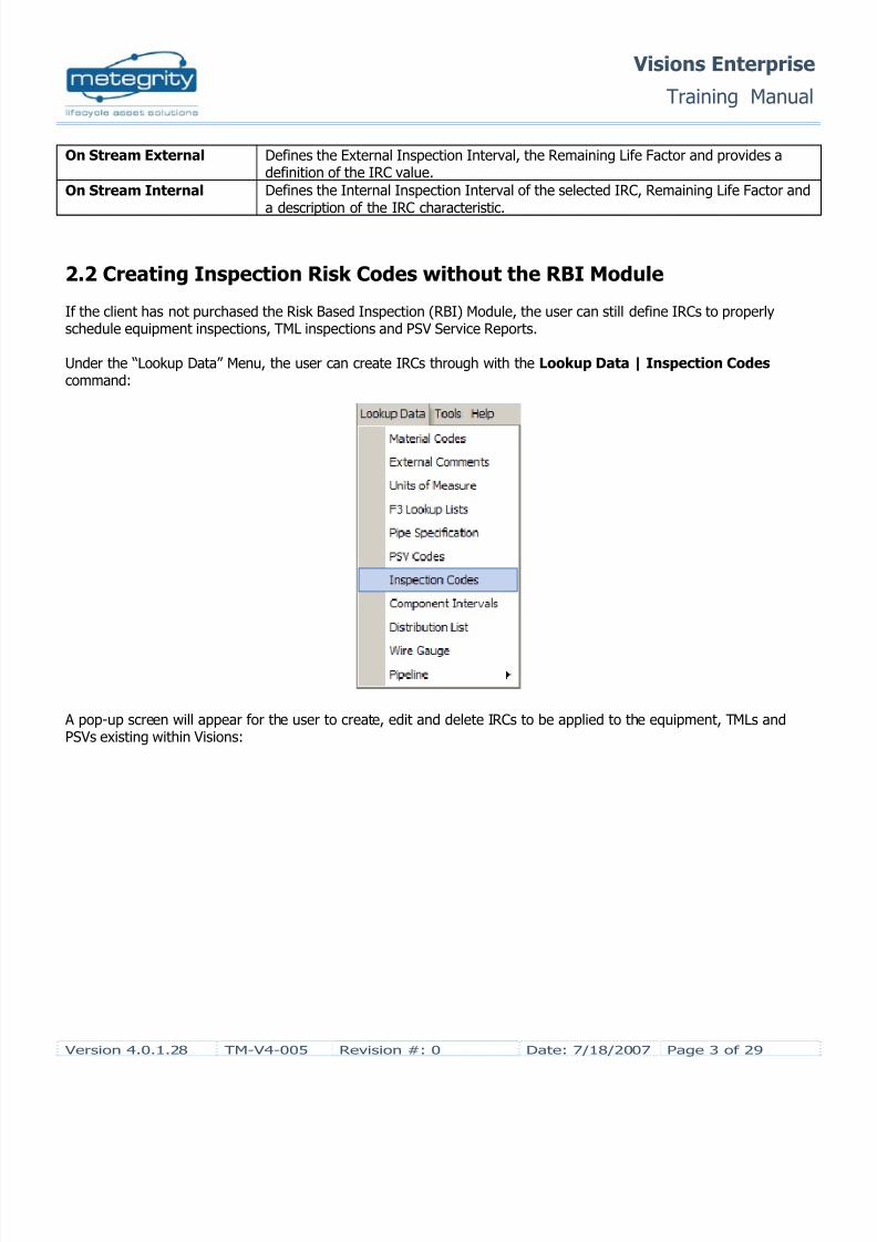
On Stream External Defines the External Inspection Interval, the Remaining Life Factor and provides adefinition of the IRC value.
On Stream Internal Defines the Internal Inspection Interval of the selected IRC, Remaining Life Factor anda description of the IRC characteristic.
2.2 Creating Inspection Risk Codes without the RBI Module
If the client has not purchased the Risk Based Inspection (RBI) Module, the user can still define IRCs to properlyschedule equipment inspections, TML inspections and PSV Service Reports.
Under the “Lookup Data” Menu, the user can create IRCs through with the Lookup Data | Inspection Codes command:
A pop-up screen will appear for the user to create, edit and delete IRCs to be applied to the equipment, TMLs andPSVs existing within Visions:

8/12/2019 TM V4 005 IRC Configuration
http://slidepdf.com/reader/full/tm-v4-005-irc-configuration 4/29
Visions Enterprise
Training Manual
Version 4.0.1.28 TM-V4-005 Revision #: 0 Date: 7/18/2007 Page 4 of 29
The functionality of the above table is the same as the functionality of the table described in Section 2.1.The user is able to create as many IRC values as necessary to properly schedule equipment, TML and PSV scheduling.
2.3 Creating Inspection Risk Codes with RBI Configuration Module
To create, edit or copy IRCs, the user must go to the RBI Configuration command, located under the Configurationsmenu.

8/12/2019 TM V4 005 IRC Configuration
http://slidepdf.com/reader/full/tm-v4-005-irc-configuration 5/29
Visions Enterprise
Training Manual
Version 4.0.1.28 TM-V4-005 Revision #: 0 Date: 7/18/2007 Page 5 of 29
Here the user will be presented with the RBI Configuration Log summarizing all currently created and completed RBIConfigurations. The Default RBI Configuration is located at the top of the list with the RAID being number 1 and titled,
“Default Configuration based on ASME standards”.
The default configuration comes with already existing IRCs and an extensive library of Degradation Modes andMechanisms that are based on API 571 standards. The user has the option to use the information presented in theDefault RAID as their RBI Assessment configuration or may clone and then edit the RAID information to better suit theequipment being assessed.
The RBI Configuration toolbar located at the top of the screen allows the user to create, edit, delete and clone RiskConfigurations.
Icon Command Function
Refresh Upon saving your recently edited RBI Configuration(s), refreshes the RBIConfiguration to present the user with previously blank fields.
Show / Hide Navigator Controls whether or not the left sidebar, called the Navigator, is displayed.
New Creates a new RBI configuration
Clone Clones an already existing RBI configuration for the purpose of editing andcreating another RBI Configuration for use on another plant, business unit,equipment type(s).
Delete Deletes the selected RBI configuration.
Open Opens the desired RBI configuration highlighted.

8/12/2019 TM V4 005 IRC Configuration
http://slidepdf.com/reader/full/tm-v4-005-irc-configuration 6/29
Visions Enterprise
Training Manual
Version 4.0.1.28 TM-V4-005 Revision #: 0 Date: 7/18/2007 Page 6 of 29
Open in New Form Allows for multiple RBI configurations to be opened at one time.
The Risk Configuration window summarizes currently existing RAIDs according to the following characteristics:
Column Header Function
RAID Visions identifier for numerically ordering RAIDs.
Date Completed Identifies the date that RAID was first created.
Title Should identify the Configuration, what equipment types it will apply to.
Complete Active Checked if the all the necessary steps to create a RAID have been carried out.
Active Checked if the RAID is available to be applied to a Risk Assessment(s).
Author
Notes
Completed RAIDs will appear in Green text while RAID that are currently not completed will appear in Red text.
Note: A RAID that has been completed can be deactivated, however, equipment that has been assessed under theRAID will still conform to the IRCs defined under the RAID until a new RBI assessment has been carried out.
Note: A RAID can only be deleted if it has not been completed. Deactivated RAIDs are unable to be deleted until allequipment conforming to the defined IRCs have been re-assessed.
2.3.1 Creating a New RBI Configuration
Unlike cloning the Default RAID or other created RAID configuration a new configuration will present the user with no
pre-existing IRC definitions, Degradation Modes and related Mechanisms or Risk Matrix and will allow the user to startfrom scratch.
Clicking on the “New” icon located on the Risk Configuration toolbar will open a new RAID window.

8/12/2019 TM V4 005 IRC Configuration
http://slidepdf.com/reader/full/tm-v4-005-irc-configuration 7/29
Visions Enterprise
Training Manual
Version 4.0.1.28 TM-V4-005 Revision #: 0 Date: 7/18/2007 Page 7 of 29
Colored fields are mandatory. The RAID information in the red box is read-only and is always displayed.
2.3.2 Information
The Information tab summarizes the characteristics of the RAID and governing equations:

8/12/2019 TM V4 005 IRC Configuration
http://slidepdf.com/reader/full/tm-v4-005-irc-configuration 8/29
Visions Enterprise
Training Manual
Version 4.0.1.28 TM-V4-005 Revision #: 0 Date: 7/18/2007 Page 8 of 29
It is broken into two (2) sections:
• RAID Information• Axis Definitions
2.3.2.1 RAID Information

8/12/2019 TM V4 005 IRC Configuration
http://slidepdf.com/reader/full/tm-v4-005-irc-configuration 9/29
Visions Enterprise
Training Manual
Version 4.0.1.28 TM-V4-005 Revision #: 0 Date: 7/18/2007 Page 9 of 29
Field Function
Author Defaults to the username of the person who has created the RAID. Can be edited todisplay whatever is required.
Matrix Size Defines the Length and Height of the Risk Matrix.
Display Using IRC Number or IRC Name to be displayed on the Risk Matrix.
Completed Checked if the RAID is completed.
Active Checked if the RAID is available to be used in Risk Assessments.
Comments Any miscellaneous notes about the RAID.
2.3.1.2 Axis Definitions
Field Function
Equation X Displays the Equation for X-Value of the RAID as defined in the Equations Tab (SeeSection 2.3.5)
X Axis Label Identifies the definition of the X-Axis of the RAID.
X Axis Order Ascending or Descending in Value along the X-Axis.
Equation Y Displays the Equation for X-Value of the RAID as defined in the Equations Tab (SeeSection 2.3.5)
Y Axis Label Identifies the definition of the Y-Axis of the RAID.
Y Axis Order Ascending or Descending in Value along the Y-Axis.

8/12/2019 TM V4 005 IRC Configuration
http://slidepdf.com/reader/full/tm-v4-005-irc-configuration 10/29
Visions Enterprise
Training Manual
Version 4.0.1.28 TM-V4-005 Revision #: 0 Date: 7/18/2007 Page 10 of 29
2.3.2 Inspection Risk Codes
Creating an IRC involves noting the:
• IRC Value• Restricted Interval (External) Frequency• Restricted Interval (Internal) Frequency
All created IRCs are summarized in the IRC summary located in the middle of the page:

8/12/2019 TM V4 005 IRC Configuration
http://slidepdf.com/reader/full/tm-v4-005-irc-configuration 11/29
Visions Enterprise
Training Manual
Version 4.0.1.28 TM-V4-005 Revision #: 0 Date: 7/18/2007 Page 11 of 29
Field Function
IRC Number Identifies the Inspection Risk Code value.IRC Name Defines the Inspection Risk Code value.
Color Defines the corresponding Inspection Risk Code value.
IRC Short Name Defines the short name of the Inspection Risk Code.
Remaining Life (External) Percentage value (less than 100%) used to schedule the next inspection based on theremaining wall thickness of the equipment. (For more information on Remaining Life,See Training Manual, TM-V4-006, “TML Trending” ).
Remaining Life (Internal) Percentage value (less than 100%) used to schedule the next inspection based on theremaining wall thickness of the equipment. (For more information on Remaining Life,See Training Manual, TM-V4-006, “TML Trending” ).
The buttons used to Create, Edit and Delete IRCs are located at the top of the Inspection Risk Codes tab:
Command Function
New IRC Creates a new IRC.
Edit IRC Edits the selected IRC in the IRC Summary Table.
Delete IRC Deletes the selected IRC in the IRC Summary Table.
Clicking on “New IRC” results in a pop-up window appearing with the necessary IRC fields:

8/12/2019 TM V4 005 IRC Configuration
http://slidepdf.com/reader/full/tm-v4-005-irc-configuration 12/29
Visions Enterprise
Training Manual
Version 4.0.1.28 TM-V4-005 Revision #: 0 Date: 7/18/2007 Page 12 of 29
The colored fields are Mandatory for the user to define before the RAID can be completed and the user can haveaccess to the OK commands. However, it is suggested that all fields be completed so that the user(s) that researchIRC values can gain a clear understanding on the classification and definitions of Risk associated with RBIassessments. The definition of the IRC is separated in the three (3) sections:
• IRC Number and Naming• On Stream (External) inspection frequency• Off Stream (Internal) inspection frequency
IRC Number and Naming – Definitions
8/12/2019 TM V4 005 IRC Configuration
http://slidepdf.com/reader/full/tm-v4-005-irc-configuration 13/29
Visions Enterprise
Training Manual
Version 4.0.1.28 TM-V4-005 Revision #: 0 Date: 7/18/2007 Page 13 of 29
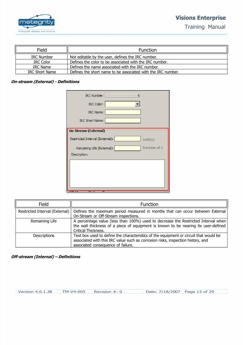
Field Function
IRC Number Not editable by the user, defines the IRC number.
IRC Color Defines the color to be associated with the IRC number.IRC Name Defines the name associated with the IRC number.
IRC Short Name Defines the short name to be associated with the IRC number.
On-stream (External) - Definitions
Field Function
Restricted Interval (External) Defines the maximum period measured in months that can occur between ExternalOn-Stream or Off-Stream inspections.
Remaining Life A percentage value (less than 100%) used to decrease the Restricted Interval whenthe wall thickness of a piece of equipment is known to be nearing its user-definedCritical Thickness.
Descriptions Text box used to define the characteristics of the equipment or circuit that would be
associated with this IRC value such as corrosion risks, inspection history, andassociated consequence of failure.
Off-stream (Internal) – Definitions

8/12/2019 TM V4 005 IRC Configuration
http://slidepdf.com/reader/full/tm-v4-005-irc-configuration 14/29
Visions Enterprise
Training Manual
Version 4.0.1.28 TM-V4-005 Revision #: 0 Date: 7/18/2007 Page 14 of 29
Field Function
Restricted Interval (Internal) Defines the maximum period measured in months that can occur between Internalinspections.
Remaining Life A percentage value (less than 100%) used to decrease the Restricted Interval when
the wall thickness of a piece of equipment is known to be nearing its user-definedCritical Thickness.
Descriptions Text box used to define the characteristics of the equipment or circuit that would beassociated with this IRC value such as corrosion risks, inspection history, andassociated consequence of failure.
2.3.3 Degradation Mechanisms

8/12/2019 TM V4 005 IRC Configuration
http://slidepdf.com/reader/full/tm-v4-005-irc-configuration 15/29
Visions Enterprise
Training Manual
Version 4.0.1.28 TM-V4-005 Revision #: 0 Date: 7/18/2007 Page 15 of 29
Degradation Mechanisms identify the corrosion risks associated with a piece of equipment and / or circuit that is to beassessed during the RBI process. As there are infinite forms Degradation available for the user to use, the RiskConfiguration simplifies the process by grouping the Degradation Mechanisms into Degradation Modes.
In addition, the user has the opportunity to define the available NDE Techniques that will aid in identifying theseDegradation Mechanisms before they lead to an equipment failure.
Degradation Mode – Definitions
The Degradation Mode defines the parent form of degradation that all related Degradation Mechanisms will bedefined under. This allows the user to quickly and easily the associated forms of Degradation during RBI Assessments.
Field Function
Degradation Mode Identifies the type of degradation the Degradation Mechanism can be associatedunder.
Description Defines the Degradation Mode.

8/12/2019 TM V4 005 IRC Configuration
http://slidepdf.com/reader/full/tm-v4-005-irc-configuration 16/29

8/12/2019 TM V4 005 IRC Configuration
http://slidepdf.com/reader/full/tm-v4-005-irc-configuration 17/29
Visions Enterprise
Training Manual
Version 4.0.1.28 TM-V4-005 Revision #: 0 Date: 7/18/2007 Page 17 of 29
2.3.4 Risk Factors
For API 580 and 581 Risk Assessments, the Risk Factor values are used to determine the Likelihood andConsequence of Failure. Within the Likelihood and Consequence of Failure, the user can create variables that willquantify these two Risk Factors. The defaults variables within the default RAID are defined as follows:
Likelihood of Failure
Variable Short Name Definition
Confidence inInspection Data
InspDataConf Confidence is based on the number and type of previous inspections, as wellas the ability of previous inspection information to instill confidence in thecondition of equipment (i.e., have previous inspections and/or methods beenadequate in detecting the presence of predicted failure modes?).
Probability ofOccurrence
ProbOccur Probability of failure occurrence is scored subjectively based on knowledge ofprocess chemistries, conditions and past experience / history of degradation

8/12/2019 TM V4 005 IRC Configuration
http://slidepdf.com/reader/full/tm-v4-005-irc-configuration 18/29
Visions Enterprise
Training Manual
Version 4.0.1.28 TM-V4-005 Revision #: 0 Date: 7/18/2007 Page 18 of 29
within specific or similar equipment.
Predictability ofDamagedLocations
PredDamLoc Predictability of failure mode occurrence is scored subjectively by person(s)knowledgeable in corrosion mechanisms and specific processes and is afunction of how well one might predict where degradation may occur, whatlevel of confidence is there in previous inspection data, and how effectiveinspection techniques are in detecting deterioration.
Consequence of Failure
Variable Short Name Definition
Release Rate RelRate Considers the type of failure, pressures associated and commodity state (liquid,vapor, gas). Differentiate a catastrophic or burst type failure to that of aweeping failure such as a pit or crack. Consider only the rate of release based onthe size of opening and pressure.
Release Volume
RelVol Considers the release rate, potential volumes of product loss and the time it maytake to detect and stop or contain the release.
Toxicity /Harm
ToxHarm Considers the effect the release may have on personnel and/or the public.Considers the toxic nature of the product, pressure involved, failure type andtemperature of the product (i.e., while water may pose no toxicity threat,sufficient pressure and temperature may pose a significant threat).
Flammability Flam Considers the combustible nature of the product, which could greatly impact theoverall consequence of a failure event. Consider the ignition properties as wellas the flammable nature.
BusinessImpact
BizImp Considering the type and location of failure, assess the potential impact toproduction losses, repair and costs / durations, impacts to related operations orequipment, and company image in the eyes of regulators, insurers, the publicand external clients.
Environmental
Impact
EnvImp Considering the rate and nature of release, the damaging properties of the
product and ability of the product to contaminate the environment based on leaklocation.
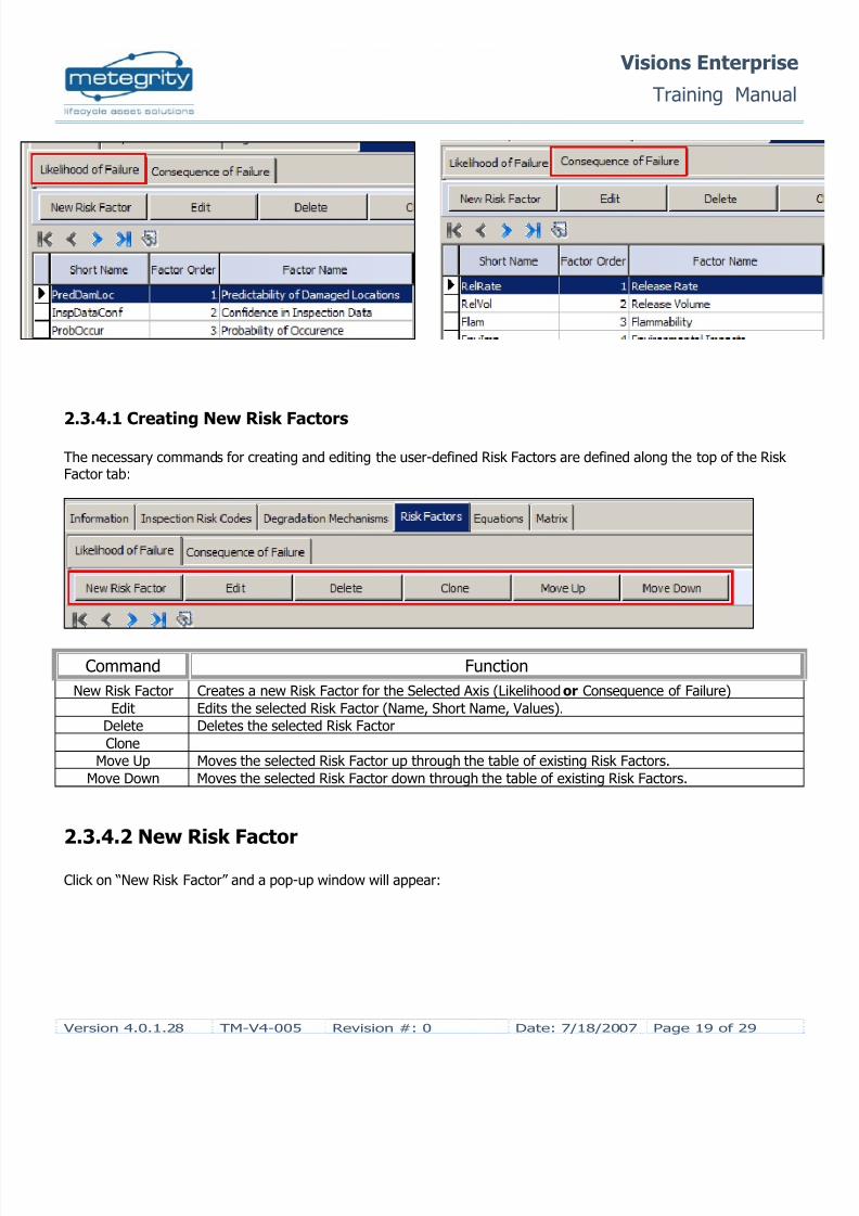
To distinguish which axis the user is viewing or editing, the Risk Factors are separated by two (2) sub-tabs at the topof the Risk Factor screen:
Clicking on the desired axis name will bring up respective screen displaying the associated Risk Factors.
8/12/2019 TM V4 005 IRC Configuration
http://slidepdf.com/reader/full/tm-v4-005-irc-configuration 19/29
Visions Enterprise
Training Manual
Version 4.0.1.28 TM-V4-005 Revision #: 0 Date: 7/18/2007 Page 19 of 29
2.3.4.1 Creating New Risk Factors
The necessary commands for creating and editing the user-defined Risk Factors are defined along the top of the RiskFactor tab:
Command Function
New Risk Factor Creates a new Risk Factor for the Selected Axis (Likelihood or Consequence of Failure)
Edit Edits the selected Risk Factor (Name, Short Name, Values).
Delete Deletes the selected Risk Factor
Clone
Move Up Moves the selected Risk Factor up through the table of existing Risk Factors.
Move Down Moves the selected Risk Factor down through the table of existing Risk Factors.
2.3.4.2 New Risk Factor
Click on “New Risk Factor” and a pop-up window will appear:

8/12/2019 TM V4 005 IRC Configuration
http://slidepdf.com/reader/full/tm-v4-005-irc-configuration 20/29
Visions Enterprise
Training Manual
Version 4.0.1.28 TM-V4-005 Revision #: 0 Date: 7/18/2007 Page 20 of 29
A Risk Factor is defined by three (3) Sections,
• Factor Information• Factor Value Definition• Lookup Table (Optional)
Factor Information – Definitions
The Risk Factor information is used to identify the specific Risk Factor to be assigned to the X or Y Axis. The user cancreate as many Risk Factors as necessary to properly calculate the X and Y Risk Values.
Field FunctionShort Name Identifies the short name of the Risk Factor that will be used in the defining the Equation in
calculating the X or Y Axis Value.
Factor Name Identifies the Risk Factor
Definition Provides a detailed definition of what the Risk Factor is measuring.
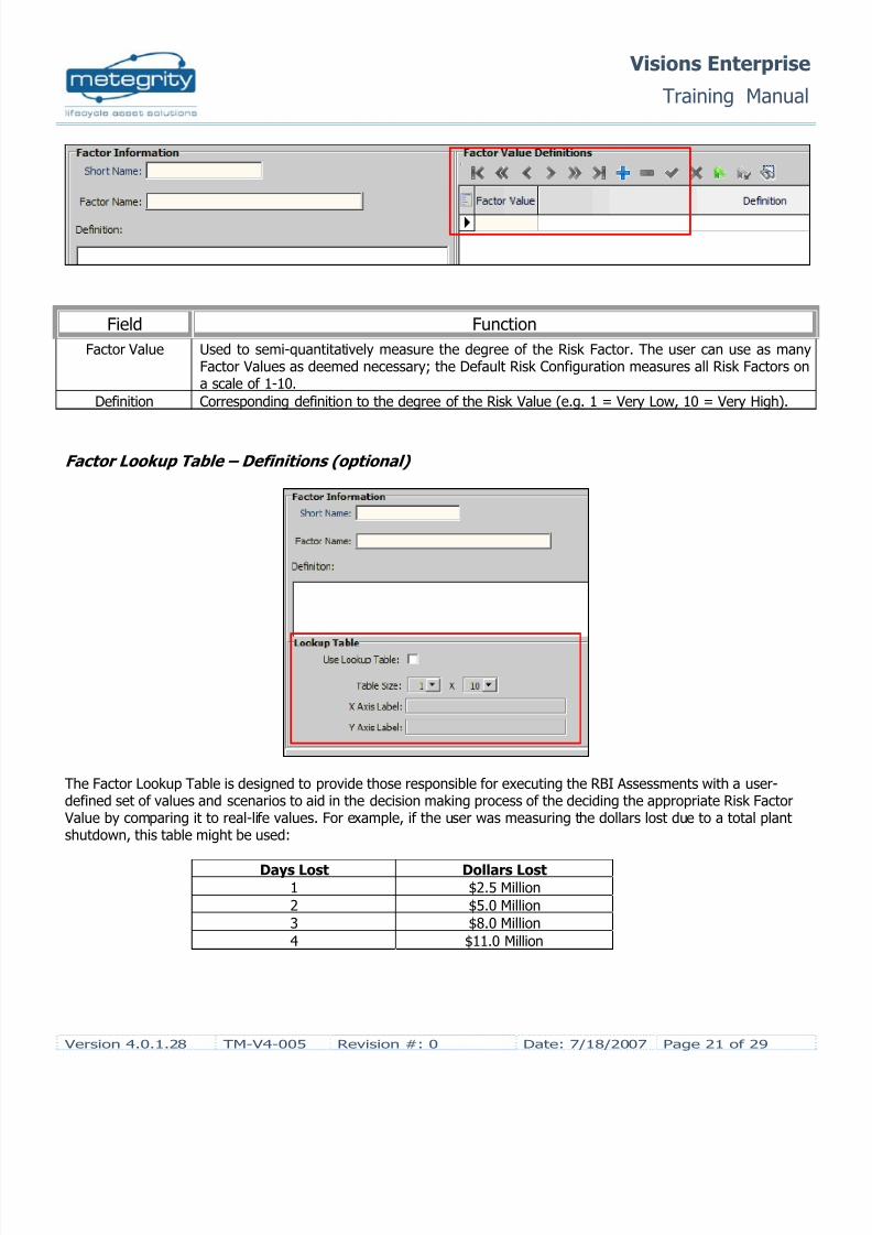
Factor Value – Definitions
8/12/2019 TM V4 005 IRC Configuration
http://slidepdf.com/reader/full/tm-v4-005-irc-configuration 21/29
Visions Enterprise
Training Manual
Version 4.0.1.28 TM-V4-005 Revision #: 0 Date: 7/18/2007 Page 21 of 29
Field Function
Factor Value Used to semi-quantitatively measure the degree of the Risk Factor. The user can use as manyFactor Values as deemed necessary; the Default Risk Configuration measures all Risk Factors ona scale of 1-10.
Definition Corresponding definition to the degree of the Risk Value (e.g. 1 = Very Low, 10 = Very High).
Factor Lookup Table – Definitions (optional)
The Factor Lookup Table is designed to provide those responsible for executing the RBI Assessments with a user-defined set of values and scenarios to aid in the decision making process of the deciding the appropriate Risk Factor Value by comparing it to real-life values. For example, if the user was measuring the dollars lost due to a total plantshutdown, this table might be used:
Days Lost Dollars Lost1 $2.5 Million
2 $5.0 Million
3 $8.0 Million
4 $11.0 Million

8/12/2019 TM V4 005 IRC Configuration
http://slidepdf.com/reader/full/tm-v4-005-irc-configuration 22/29
Visions Enterprise
Training Manual
Version 4.0.1.28 TM-V4-005 Revision #: 0 Date: 7/18/2007 Page 22 of 29
Another example would be the ranking of volume released measured against a varying hole size:
Hole Size Volume Lost
0.25” 10 Liters
0.50” 50 Liters
2.00” 175 Liters
4.00” 250 Liters
Field Function
Use Lookup Table Check if the user wishes to create a Factor Lookup Table.
Table Size Defines the size of the Factor Look up Table.
X Axis Label
Y Axis Label
2.3.5 Equations
8/12/2019 TM V4 005 IRC Configuration
http://slidepdf.com/reader/full/tm-v4-005-irc-configuration 23/29
Visions Enterprise
Training Manual
Version 4.0.1.28 TM-V4-005 Revision #: 0 Date: 7/18/2007 Page 23 of 29
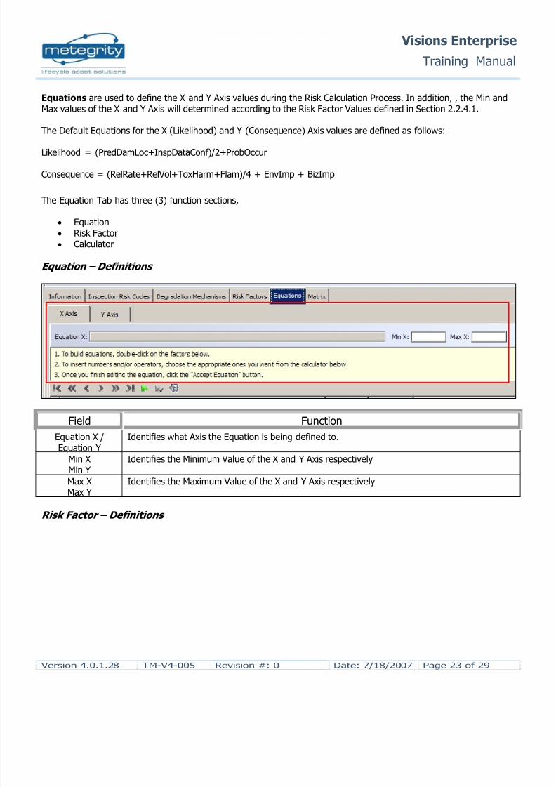
Equations are used to define the X and Y Axis values during the Risk Calculation Process. In addition, , the Min andMax values of the X and Y Axis will determined according to the Risk Factor Values defined in Section 2.2.4.1.
The Default Equations for the X (Likelihood) and Y (Consequence) Axis values are defined as follows:
Likelihood = (PredDamLoc+InspDataConf)/2+ProbOccur
Consequence = (RelRate+RelVol+ToxHarm+Flam)/4 + EnvImp + BizImp
The Equation Tab has three (3) function sections,
• Equation• Risk Factor• Calculator
Equation – Definitions
Field Function
Equation X /Equation Y
Identifies what Axis the Equation is being defined to.
Min XMin Y
Identifies the Minimum Value of the X and Y Axis respectively
Max XMax Y
Identifies the Maximum Value of the X and Y Axis respectively
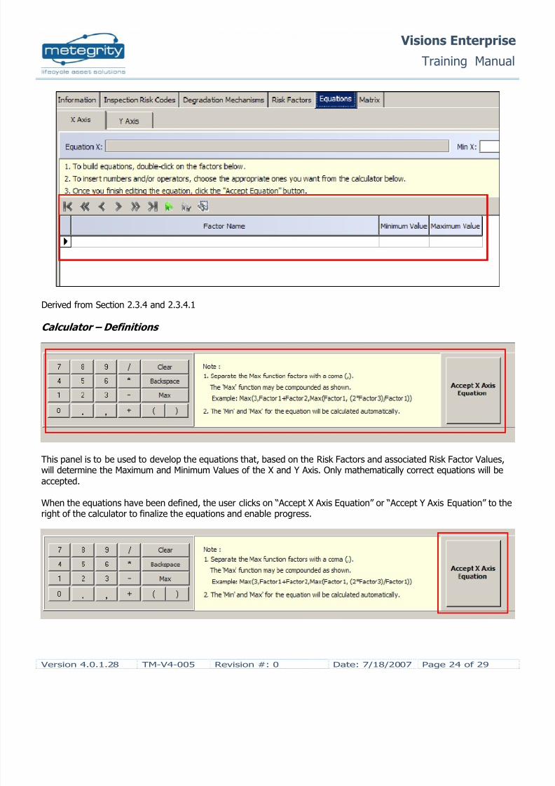
Risk Factor – Definitions
8/12/2019 TM V4 005 IRC Configuration
http://slidepdf.com/reader/full/tm-v4-005-irc-configuration 24/29
Visions Enterprise
Training Manual
Version 4.0.1.28 TM-V4-005 Revision #: 0 Date: 7/18/2007 Page 24 of 29
Derived from Section 2.3.4 and 2.3.4.1
Calculator – Definitions
This panel is to be used to develop the equations that, based on the Risk Factors and associated Risk Factor Values,will determine the Maximum and Minimum Values of the X and Y Axis. Only mathematically correct equations will beaccepted.
When the equations have been defined, the user clicks on “Accept X Axis Equation” or “Accept Y Axis Equation” to theright of the calculator to finalize the equations and enable progress.

8/12/2019 TM V4 005 IRC Configuration
http://slidepdf.com/reader/full/tm-v4-005-irc-configuration 25/29
Visions Enterprise
Training Manual
Version 4.0.1.28 TM-V4-005 Revision #: 0 Date: 7/18/2007 Page 25 of 29
2.3.6 Risk Matrix
The Risk Matrix for a newly created RAID will appear blank as follows. However, if the user has cloned a Configuration
from another RAID, the Risk Matrix will take the appearance of the original. The user has the option to reconfigure thenew or cloned matrix.
New Configuration Cloned Configuration
Along the top of the Risk Matrix Tab are three commands:
Commands Function
Complete Configuration Disables any editing of the Risk Configuration.
Activate Configuration Allows the Risk Configuration to be assigned to equipment and/or circuit RBI Assessments.
Deactivate Configuration Prevents the Risk Configuration from being assigned to equipment and/or circuit RBI Assessments.

8/12/2019 TM V4 005 IRC Configuration
http://slidepdf.com/reader/full/tm-v4-005-irc-configuration 26/29
Visions Enterprise
Training Manual
Version 4.0.1.28 TM-V4-005 Revision #: 0 Date: 7/18/2007 Page 26 of 29
To determine what IRC a given area of the Risk Matrix is to be associated with, click on the square in question:
A pop-up screen will appear summarizing all IRC values. Select the desired IRC and click on “OK”.
Along the X and Y Axis of the Risk Matrix, the user can define the intervals of the Risk Matrix grid by clicking on theincrease / decrease values. However, the Maximum and Minimum values are not editable.

8/12/2019 TM V4 005 IRC Configuration
http://slidepdf.com/reader/full/tm-v4-005-irc-configuration 27/29
Visions Enterprise
Training Manual
Version 4.0.1.28 TM-V4-005 Revision #: 0 Date: 7/18/2007 Page 27 of 29
2.3.6.1 Completing your Risk ConfigurationOnce the Risk Matrix has been defined, the user need only to click on “Complete Configuration” to allow it to be usedin future RBI Assessments.

8/12/2019 TM V4 005 IRC Configuration
http://slidepdf.com/reader/full/tm-v4-005-irc-configuration 28/29
Visions Enterprise
Training Manual
Version 4.0.1.28 TM-V4-005 Revision #: 0 Date: 7/18/2007 Page 28 of 29
If all the steps outlined in Sections 2.3 through to 2.2.6.1 are properly completed, then the user will be notified of theRisk Configuration with the pop-up message,
If the user attempts to complete the configuration before the Matrix has been properly edited, the following pop-uperror will appear,
2.4 Cloning a Risk Configuration
Cloning a Risk Configuration is useful for copying and editing a previously created RAID or the Default RiskConfiguration (RAID #1). For example, the user may wish to alter the Risk Factors, but may still want the definedDegradation Modes and Mechanisms. Another example would be to alter the ranges of the X and Y Values of the RiskMatrix while still keeping the previously entered information intact.
To clone a Risk Configuration, select the desired Risk Configuration to be cloned in the Risk Configuration Log andclick on the “Clone” button located along the toolbar,
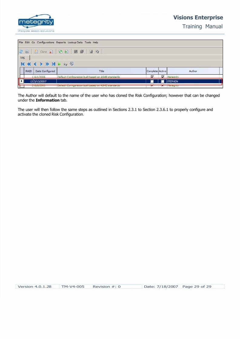
Visions will automatically create a new RAID highlighted in red text located at the base of the Risk Configuration Log,
8/12/2019 TM V4 005 IRC Configuration
http://slidepdf.com/reader/full/tm-v4-005-irc-configuration 29/29
Visions Enterprise
Training Manual
The Author will default to the name of the user who has cloned the Risk Configuration; however that can be changedunder the Information tab.
The user will then follow the same steps as outlined in Sections 2.3.1 to Section 2.3.6.1 to properly configure andactivate the cloned Risk Configuration.