
TM - m.media-amazon.com
29
S.E. Internaonal, Inc. P.O. Box 39, 436 Farm Rd. Summertown, TN 38483 USA 1.800.293.5759 | 931.964.3561 | Fax: 1.931.964.3564 www.seintl.com | [email protected] INTERNATIONAL ® TM
Transcript of TM - m.media-amazon.com
S.E. International, Inc. P.O. Box 39, 436 Farm Rd. Summertown, TN 38483 USA 1.800.293.5759 | 931.964.3561 | Fax: 1.931.964.3564
www.seintl.com | [email protected]
INTERNATIONAL
®
TM
2
The X Axis 15The Y Axis 15Observer USB Meter Screen 15Enable Alarm 15Zero 15Units/Echo Display 15Averaging Time 15
Chapter 8: Observer USB Calibration Software 16General Discussion of Calibration 16Pulse Calibration 16Efficiency Calibration 17Exposure Rate Calibration 19
Chapter 9: Built in Isotope Efficiencies 20Built in Isotope Efficiencies 20Decay 20Selecting a Built-In Isotope Efficiency 20Selecting Between DPM and Bq 20
Chapter 10: Troubleshooting 21
Chapter 11: Basics of Taking Measurements 22How to Detect Background Radiation 22How To Survey a Surface 22How to Perform a General Survey 22How to Determine Alpha, Beta, or Gamma source. 23Radiation Measurement Units 24Converting CPM to mR/hr 24
Chapter 12: Glossary of Common Terms 25Background Radiation 25CPM (counts per minute) 25Ion 25Ionization 25Ionizing Radiation 25Radiation 25Radionuclide 25Decay 25Half-life 25
Chapter 13: Accessories 26Xtreme Boot 26Wipe Test Plate 26Stand 26
Appendix A: Technical Specifications 27
Appendix B: Limited Warranty 28
Calibration Database Application 29
Contents
Chapter 1: Introduction 3How The Inspector Detects Radiation 3Precautions 3
Chapter 2: Features 4The LCD Display 4Indicators 4The Switches 5Mode Switch 5Off/On/Audio Switch 5The Backlight 5Set Button 6+ and - Buttons 6The Detector 6The Input/Output Ports 6
Chapter 3: Operation 7Starting the Inspector 7Units of Measurement 7Display Update 7Maximum level 7Response Time (Autoaveraging) 7Autoranging 8Operating in Dose/Rate Modes 8Operating in Timer Mode 8Taking a Timed Count 8Using Dose/Rate Modes While Timer is On 9Using The Alert 9Utility Menu 10Options 10Setting the Internal Clock 11Interfacing with an External Device 11
Chapter 4: Common Procedures 11Establishing the Background Count 11Environmental Area Monitoring 11Checking for Surface Contamination 12
Chapter 5: Maintenance 12Calibration 12General Maintenance Tips 12
Chapter 6: Basics of Radiation and Its Measurement 13Ionizing Radiation 13Types of Ionizing Radiation 13X-Rays 13Gamma Rays 13Beta Radiation 13Alpha Particles 13
Chapter 7: Observer USB Software 14Installing the Observer USB Software 14Connect to The Inspector 14Preferences 14Using the Data Logging Feature 14Show Grid 15Observer USB Chart Screen 15
3
Chapter 1: IntroductionThe Inspector is a health and safety instrument that is optimized to detect low levels of radiation. It measures alpha, beta, gamma, and x-ray radiation (ionizing radiation only).Its applications include:
• Detecting and measuring surface contamination• Monitoring possible radiation exposure while working with radionuclides• Screening for environmental contamination• Detecting noble gases and other low energy radionuclides
How The Inspector Detects RadiationThe Inspector uses a Geiger-Mueller tube to detect radiation. The Geiger tube generates a pulse of electrical current each time radiation passes through the halogen quenched tube and causes ionization. Each pulse is electronically detected and registers as a count. The Inspector displays the counts in the mode you choose.
The number of counts detected by the Inspector varies from moment to moment due to the random nature of radioactivity. A reading is expressed more accurately as an average over time, and the average is more accurate over a longer time period. For details, see Operating in Timer Mode in Chapter 3.
PrecautionsTo keep the Inspector in good condition, handle it with care, and observe the following precautions:
• CAUTION: Never touch the Inspector to a surface that may be contaminated. You may contaminate the instrument.
• Do not leave the Inspector in temperatures over 100° F (38° C) or in direct sunlight for extended periods of time.
• Do not get the Inspector wet. Water can damage the circuitry and the mica surface of the Geiger tube.• Do not put the Inspector in a microwave oven. It cannot measure microwaves, and you may damage it or
the oven.• This instrument may be sensitive to and may not operate properly in radio frequency, microwave,
electrostatic, and electromagnetic fields.• If you do not expect to use the Inspector for longer than one month, remove the battery to avoid damage
from battery corrosion. Change the battery promptly when the battery indicator appears on the display.• CAUTION: When using the unit at altitudes higher than 8000 feet (2438.4 meters), it is possible that the
tube window can rupture.
4
Chapter 2: FeaturesThe Inspector measures alpha, beta, gamma, and x-ray radiation. It is optimized to detect small changes in radiation levels and to have high sensitivity to many common radionuclides. For more information, see Appendix A, Sensitivity to Common Radionuclides. This chapter briefly describes the Inspector’s functions. For more information on how to use the Inspector, see Chapter 3: Operation. The Inspector counts ionizing events and displays the results on the liquid crystal display (LCD). You control which unit of measurement is shown by using the mode switch. Whenever the Inspector is operating, the red count light flashes each time a count (an ionizing event) is detected Figure 2 (8).
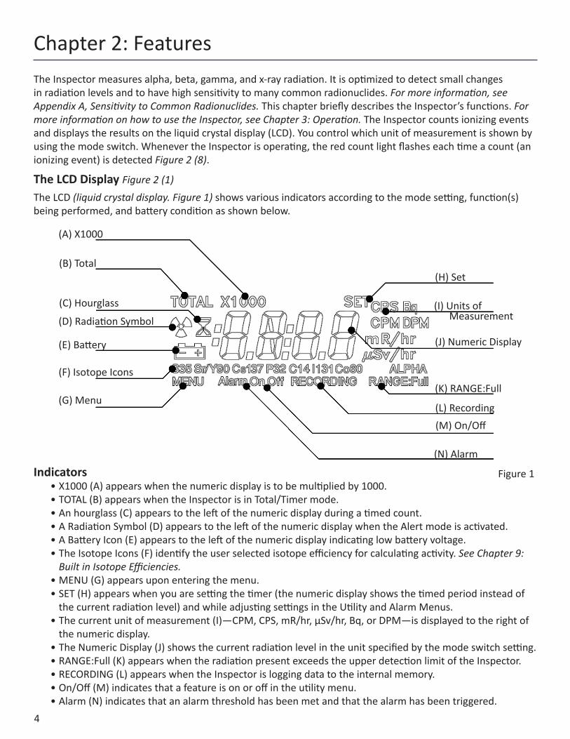
The LCD Display Figure 2 (1)The LCD (liquid crystal display. Figure 1) shows various indicators according to the mode setting, function(s) being performed, and battery condition as shown below.
Indicators• X1000 (A) appears when the numeric display is to be multiplied by 1000. • TOTAL (B) appears when the Inspector is in Total/Timer mode. • An hourglass (C) appears to the left of the numeric display during a timed count. • A Radiation Symbol (D) appears to the left of the numeric display when the Alert mode is activated.• A Battery Icon (E) appears to the left of the numeric display indicating low battery voltage.• The Isotope Icons (F) identify the user selected isotope efficiency for calculating activity. See Chapter 9:
Built in Isotope Efficiencies.• MENU (G) appears upon entering the menu.• SET (H) appears when you are setting the timer (the numeric display shows the timed period instead of
the current radiation level) and while adjusting settings in the Utility and Alarm Menus.• The current unit of measurement (I)—CPM, CPS, mR/hr, µSv/hr, Bq, or DPM—is displayed to the right of
the numeric display.• The Numeric Display (J) shows the current radiation level in the unit specified by the mode switch setting.• RANGE:Full (K) appears when the radiation present exceeds the upper detection limit of the Inspector.• RECORDING (L) appears when the Inspector is logging data to the internal memory.• On/Off (M) indicates that a feature is on or off in the utility menu.• Alarm (N) indicates that an alarm threshold has been met and that the alarm has been triggered.
Figure 1
(A) X1000
(B) Total
(C) Hourglass
(D) Radiation Symbol
(E) Battery
(F) Isotope Icons
(G) Menu
(H) Set
(I) Units of Measurement
(J) Numeric Display
(K) RANGE:Full
(L) Recording(M) On/Off
(N) Alarm
5
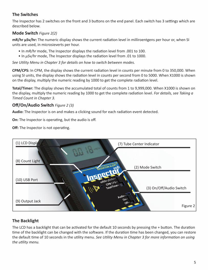
The SwitchesThe Inspector has 2 switches on the front and 3 buttons on the end panel. Each switch has 3 settings which are described below.
Mode Switch Figure 2(2)mR/hr µSv/hr: The numeric display shows the current radiation level in milliroentgens per hour or, when SI units are used, in microsieverts per hour.
• In mR/hr mode, The Inspector displays the radiation level from .001 to 100.• In µSv/hr mode, The Inspector displays the radiation level from .01 to 1000.
See Utility Menu in Chapter 3 for details on how to switch between modes.
CPM/CPS: In CPM, the display shows the current radiation level in counts per minute from 0 to 350,000. When using SI units, the display shows the radiation level in counts per second from 0 to 5000. When X1000 is shown on the display, multiply the numeric reading by 1000 to get the complete radiation level.
Total/Timer: The display shows the accumulated total of counts from 1 to 9,999,000. When X1000 is shown on the display, multiply the numeric reading by 1000 to get the complete radiation level. For details, see Taking a Timed Count in Chapter 3.
Off/On/Audio Switch Figure 2 (3)Audio: The Inspector is on and makes a clicking sound for each radiation event detected.
On: The Inspector is operating, but the audio is off.
Off: The Inspector is not operating.
The BacklightThe LCD has a backlight that can be activated for the default 10 seconds by pressing the + button. The duration time of the backlight can be changed with the software. If the duration time has been changed, you can restore the default time of 10 seconds in the utility menu. See Utility Menu in Chapter 3 for more information on using the utility menu.
(1) LCD Display
(8) Count Light
(10) USB Port
(9) Output Jack
(7) Tube Center Indicator
(2) Mode Switch
(3) On/Off/Audio Switch
Figure 2
6
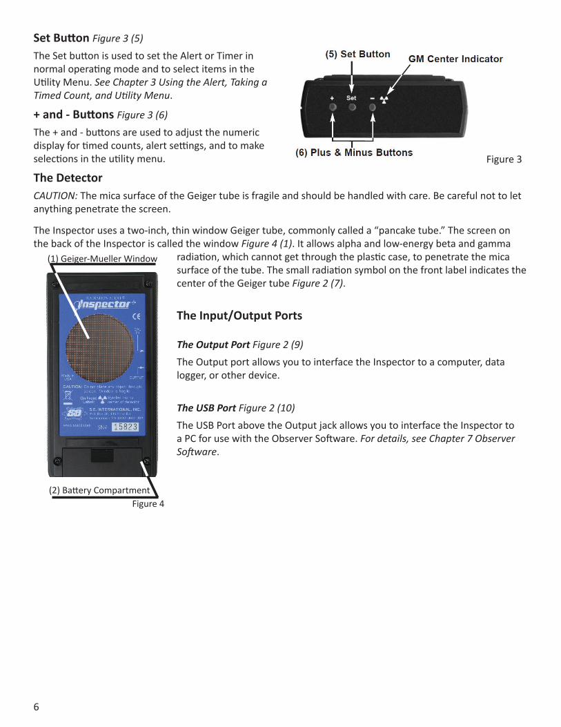
Set Button Figure 3 (5)The Set button is used to set the Alert or Timer in normal operating mode and to select items in the Utility Menu. See Chapter 3 Using the Alert, Taking a Timed Count, and Utility Menu.
+ and - Buttons Figure 3 (6)The + and - buttons are used to adjust the numeric display for timed counts, alert settings, and to make selections in the utility menu.
The DetectorCAUTION: The mica surface of the Geiger tube is fragile and should be handled with care. Be careful not to let anything penetrate the screen.
The Inspector uses a two-inch, thin window Geiger tube, commonly called a “pancake tube.” The screen on the back of the Inspector is called the window Figure 4 (1). It allows alpha and low-energy beta and gamma
radiation, which cannot get through the plastic case, to penetrate the mica surface of the tube. The small radiation symbol on the front label indicates the center of the Geiger tube Figure 2 (7).
The Input/Output Ports
The Output Port Figure 2 (9)The Output port allows you to interface the Inspector to a computer, data logger, or other device.
The USB Port Figure 2 (10) The USB Port above the Output jack allows you to interface the Inspector to a PC for use with the Observer Software. For details, see Chapter 7 Observer Software.
Figure 3
(1) Geiger-Mueller Window
(2) Battery CompartmentFigure 4
7
Chapter 3: OperationStarting the InspectorBefore starting the Inspector, install a standard 9-volt alkaline battery in the battery compartment located in the lower rear (Figure 4). Note: Place the battery against the bottom wall, and make sure the wires are placed along the side of the battery and not under it.
To start the Inspector, set the mode switch to the mode you want, and set the bottom switch to On or Audio. The Inspector then begins a 6-second system check. All indicators and numbers are displayed. After the system check, the radiation level is displayed in the selected mode. Approximately 30 seconds after you start the Inspector, a short beep indicates that enough information has been collected to ensure statistical validity.
Units of MeasurementThe Inspector is designed for use of conventional units; milliroentgens per hour (mR/hr) and counts per minute (CPM) or SI units microsieverts per hour (µSv/hr) and counts per second (CPS). To switch between conventional or SI units choose UNITS in the Utility Menu. For details, see Utility Menu in Chapter 3.
Display UpdateIn the dose, rate, and count modes, the numeric display is updated every 3 seconds. In Timer mode, the numeric display is updated every second.
Maximum levelWhen the maximum level for the current mode is reached, the Inspector beeps for 3 seconds, pauses for 3 seconds, and repeats that pattern. Also, the RANGE:Full icon is displayed and the numerical values displayed will show OVER instead of the specific rate. The beeping pattern and the flashing display continue until the level decreases or the Inspector is turned off.
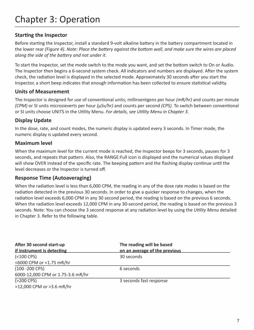
Response Time (Autoaveraging) When the radiation level is less than 6,000 CPM, the reading in any of the dose rate modes is based on the radiation detected in the previous 30 seconds. In order to give a quicker response to changes, when the radiation level exceeds 6,000 CPM in any 30 second period, the reading is based on the previous 6 seconds. When the radiation level exceeds 12,000 CPM in any 30-second period, the reading is based on the previous 3 seconds. Note: You can choose the 3 second response at any radiation level by using the Utility Menu detailed in Chapter 3. Refer to the following table.
After 30 second start-up The reading will be based if instrument is detecting on an average of the previous(<100 CPS) 30 seconds <6000 CPM or <1.75 mR/hr(100 -200 CPS) 6 seconds6000-12,000 CPM or 1.75-3.6 mR/hr(>200 CPS) 3 seconds fast response>12,000 CPM or >3.6 mR/hr
8
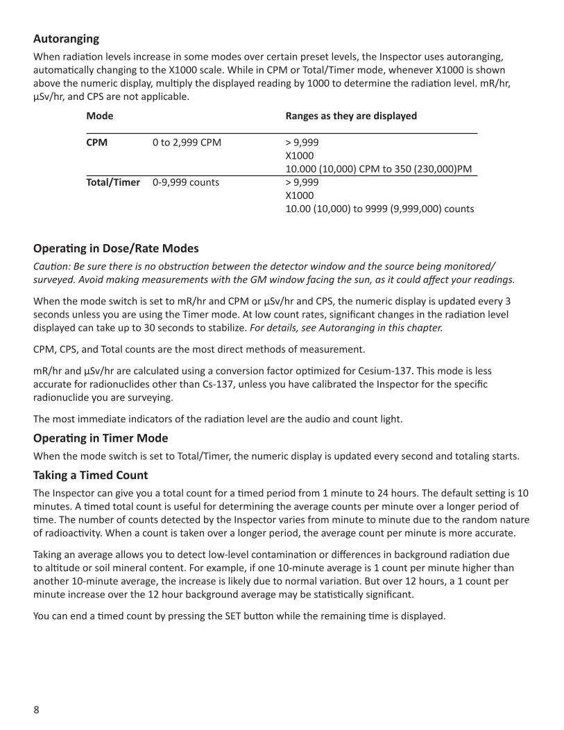
AutorangingWhen radiation levels increase in some modes over certain preset levels, the Inspector uses autoranging, automatically changing to the X1000 scale. While in CPM or Total/Timer mode, whenever X1000 is shown above the numeric display, multiply the displayed reading by 1000 to determine the radiation level. mR/hr, µSv/hr, and CPS are not applicable.
Operating in Dose/Rate ModesCaution: Be sure there is no obstruction between the detector window and the source being monitored/surveyed. Avoid making measurements with the GM window facing the sun, as it could affect your readings.
When the mode switch is set to mR/hr and CPM or µSv/hr and CPS, the numeric display is updated every 3 seconds unless you are using the Timer mode. At low count rates, significant changes in the radiation level displayed can take up to 30 seconds to stabilize. For details, see Autoranging in this chapter.
CPM, CPS, and Total counts are the most direct methods of measurement.
mR/hr and µSv/hr are calculated using a conversion factor optimized for Cesium-137. This mode is less accurate for radionuclides other than Cs-137, unless you have calibrated the Inspector for the specific radionuclide you are surveying.
The most immediate indicators of the radiation level are the audio and count light.
Operating in Timer ModeWhen the mode switch is set to Total/Timer, the numeric display is updated every second and totaling starts.
Taking a Timed CountThe Inspector can give you a total count for a timed period from 1 minute to 24 hours. The default setting is 10 minutes. A timed total count is useful for determining the average counts per minute over a longer period of time. The number of counts detected by the Inspector varies from minute to minute due to the random nature of radioactivity. When a count is taken over a longer period, the average count per minute is more accurate.
Taking an average allows you to detect low-level contamination or differences in background radiation due to altitude or soil mineral content. For example, if one 10-minute average is 1 count per minute higher than another 10-minute average, the increase is likely due to normal variation. But over 12 hours, a 1 count per minute increase over the 12 hour background average may be statistically significant.
You can end a timed count by pressing the SET button while the remaining time is displayed.
Mode Ranges as they are displayed
CPM 0 to 2,999 CPM > 9,999 X1000 10.000 (10,000) CPM to 350 (230,000)PMTotal/Timer 0-9,999 counts > 9,999 X1000 10.00 (10,000) to 9999 (9,999,000) counts
9
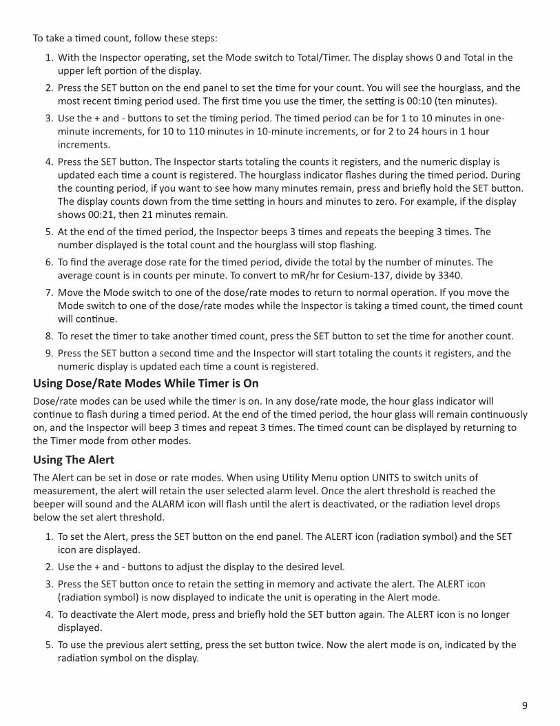
To take a timed count, follow these steps:
1. With the Inspector operating, set the Mode switch to Total/Timer. The display shows 0 and Total in the upper left portion of the display.
2. Press the SET button on the end panel to set the time for your count. You will see the hourglass, and the most recent timing period used. The first time you use the timer, the setting is 00:10 (ten minutes).
3. Use the + and - buttons to set the timing period. The timed period can be for 1 to 10 minutes in one-minute increments, for 10 to 110 minutes in 10-minute increments, or for 2 to 24 hours in 1 hour increments.
4. Press the SET button. The Inspector starts totaling the counts it registers, and the numeric display is updated each time a count is registered. The hourglass indicator flashes during the timed period. During the counting period, if you want to see how many minutes remain, press and briefly hold the SET button. The display counts down from the time setting in hours and minutes to zero. For example, if the display shows 00:21, then 21 minutes remain.
5. At the end of the timed period, the Inspector beeps 3 times and repeats the beeping 3 times. The number displayed is the total count and the hourglass will stop flashing.
6. To find the average dose rate for the timed period, divide the total by the number of minutes. The average count is in counts per minute. To convert to mR/hr for Cesium-137, divide by 3340.
7. Move the Mode switch to one of the dose/rate modes to return to normal operation. If you move the Mode switch to one of the dose/rate modes while the Inspector is taking a timed count, the timed count will continue.
8. To reset the timer to take another timed count, press the SET button to set the time for another count.9. Press the SET button a second time and the Inspector will start totaling the counts it registers, and the
numeric display is updated each time a count is registered.Using Dose/Rate Modes While Timer is OnDose/rate modes can be used while the timer is on. In any dose/rate mode, the hour glass indicator will continue to flash during a timed period. At the end of the timed period, the hour glass will remain continuously on, and the Inspector will beep 3 times and repeat 3 times. The timed count can be displayed by returning to the Timer mode from other modes.
Using The AlertThe Alert can be set in dose or rate modes. When using Utility Menu option UNITS to switch units of measurement, the alert will retain the user selected alarm level. Once the alert threshold is reached the beeper will sound and the ALARM icon will flash until the alert is deactivated, or the radiation level drops below the set alert threshold.
1. To set the Alert, press the SET button on the end panel. The ALERT icon (radiation symbol) and the SET icon are displayed.
2. Use the + and - buttons to adjust the display to the desired level.3. Press the SET button once to retain the setting in memory and activate the alert. The ALERT icon
(radiation symbol) is now displayed to indicate the unit is operating in the Alert mode.4. To deactivate the Alert mode, press and briefly hold the SET button again. The ALERT icon is no longer
displayed.5. To use the previous alert setting, press the set button twice. Now the alert mode is on, indicated by the
radiation symbol on the display.
10
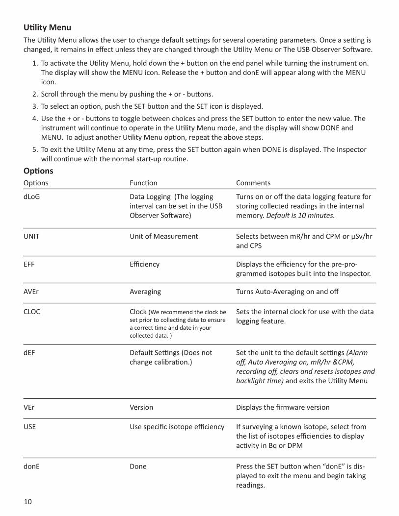
Utility MenuThe Utility Menu allows the user to change default settings for several operating parameters. Once a setting is changed, it remains in effect unless they are changed through the Utility Menu or The USB Observer Software.
1. To activate the Utility Menu, hold down the + button on the end panel while turning the instrument on. The display will show the MENU icon. Release the + button and donE will appear along with the MENU icon.
2. Scroll through the menu by pushing the + or - buttons.3. To select an option, push the SET button and the SET icon is displayed.4. Use the + or - buttons to toggle between choices and press the SET button to enter the new value. The
instrument will continue to operate in the Utility Menu mode, and the display will show DONE and MENU. To adjust another Utility Menu option, repeat the above steps.
5. To exit the Utility Menu at any time, press the SET button again when DONE is displayed. The Inspector will continue with the normal start-up routine.
OptionsOptions Function Comments
dLoG Data Logging (The logging interval can be set in the USB Observer Software)
Turns on or off the data logging feature for storing collected readings in the internal memory. Default is 10 minutes.
UNIT Unit of Measurement Selects between mR/hr and CPM or μSv/hr and CPS
EFF Efficiency Displays the efficiency for the pre-pro-grammed isotopes built into the Inspector.
CLOC Clock (We recommend the clock be set prior to collecting data to ensure a correct time and date in your collected data. )
Sets the internal clock for use with the data logging feature.
dEF Default Settings (Does not change calibration.)
Set the unit to the default settings (Alarm off, Auto Averaging on, mR/hr &CPM, recording off, clears and resets isotopes and backlight time) and exits the Utility Menu
VEr Version Displays the firmware version
USE Use specific isotope efficiency If surveying a known isotope, select from the list of isotopes efficiencies to display activity in Bq or DPM
donE Done Press the SET button when “donE” is dis-played to exit the menu and begin taking readings.
AVEr Averaging Turns Auto-Averaging on and off
11
Chapter 4: Common Procedures
Setting the Internal ClockIt is necessary to set the internal clock to properly time stamp the data collection on your device. We recommend the clock be set prior to collecting data to ensure a correct time and date in your collected data. The unit will beep three times on start up if the clock has been reset.
To set the internal clock, enter into the utility menu, select CLOC, and press set.
1. The seconds are displayed. Use the + and - buttons to select the seconds for the clock and press SET to select your choice.
2. The time will be displayed. The minutes will flash while using the + and - buttons to select the desired minutes and press SET. You will then select the hour and press SET again.
3. The date will be displayed. First set the day and press SET. Then select the month and press SET.4. The year will be displayed. Select the appropriate year and press SET.
You will now see donE displayed in the Utility Menu. You can now select another item in the Utility Menu or press SET to enter into the normal function of the Inspector.
Interfacing with an External DeviceThe USB jack on the left side of the Inspector provides an interface for use with the USB Observer Software Figure 2(10). You can use it to record the counts on a computer, download the recorded data, and calibrate the instrument. For details, see Chapter 7 Observer Software.
The following sections give instructions for several commonly-used procedures. With any procedure, the user must determine the suitability of the instrument or procedure for that application.
Establishing the Background Count Normal background radiation levels vary at different locations, different times, even in different areas of the same room. To accurately interpret the readings you get on the Inspector, it is good to establish the normal background radiation count rate for each area you plan to monitor. You can do this by taking a timed count. For more information on using the timer, see Taking a Timed Count in Chapter 3.
A 10-minute average is moderately accurate. You can repeat it several times and compare the results to establish accuracy. To establish a more accurate average, take a 1 hour timed count. If you need to determine whether there is prior contamination, take averages in several locations, and compare the averages.
Environmental Area MonitoringYou can keep the Inspector in CPM or mR/hr mode whenever you want to monitor the ambient radiation, and look at it from time to time to check for elevated readings.
If you suspect an increase in ambient radiation, use the timer and take a 5 or 10 minute count, and compare the average to your average background count. If you suspect an increase that is too small to detect with a short timed reading, you can take a longer count (for example 6, 12, or 24 hours).
12
The Inspector requires regular calibration and careful handling to assure good measurements. Use the following guidelines to maintain the instrument properly.
CalibrationWe recommend that the Inspector be calibrated annually, or as often as your regulations require. The best way to calibrate is using a calibrated source at a calibration lab. However, if no source is available, it is possible to calibrate electronically using the calibration software. See Chapter 8 for more information.
The standard by which the Inspector is calibrated is Cesium-137. A certified calibration source should be used. To calibrate the Inspector for another radionuclide, use a calibrated source for that radionuclide or the appropriate conversion factor referenced to Cs-137. CAUTION: Errors can occur when using low level sources or background for calibrating. In the Calibration mode, the smallest increment which can be adjusted is .010.
If you would like more information about source calibrations, please contact us at 1.800.293.5759 or go to seintl.com/services.
General Maintenance Tips1. Do not get the instrument wet.2. Be sure to store the meter in a location without direct sunlight, as sunlight can damage the end window
of the detector over time.3. Be sure to store the unit inside the carrying case when not in use.4. If you are planning to store the unit for a long time, remove the battery to avoid battery corrosion inside
the battery compartment.5. Do not place the unit inside a microwave oven as it can damage the unit and/or the microwave. This
instrument is for detecting ionizing radiation such as alpha, beta, gamma, and x-rays. It will not detect non-ionizing radiation such as microwave and radio emissions.
6. Do not place any objects that may puncture the mica end window of the detector near the detector.
Chapter 5: Maintenance
Checking for Surface ContaminationTo check a surface, hold the detector window close to the surface, and read the count rate (wait 30 seconds or until the reading has stabilized). If you want to find out if a surface is slightly radioactive, take a timed count or a longer accumulated count.
13
Ionizing Radiation Ionizing radiation changes the structure of individual atoms by ionizing them. The ions produced in turn ionize more atoms. Substances that produce ionizing radiation are called radioactive. Radioactivity is a natural phenomenon. Nuclear reactions take place continuously on the sun and all other stars. The emitted radiation travels through space and a small fraction reaches the Earth. Natural sources of ionizing radiation also exist in people and in the ground. The most common sources of ground radiation are uranium and its decay products
Types of Ionizing Radiation
X-RaysX-rays are man made radiation produced by bombarding a metallic target with electrons at a high speed in a vacuum. X-rays are electromagnetic radiation of the same nature as light waves and radio waves, but at extremely short wavelength, less than 0.1 billionth of a centimeter. They are also called photons. The energy of X-rays are millions of times greater than that of light and radio waves. Because of this high energy level, X-rays penetrate a variety of materials, including body tissue.
Electromagnetic radiation (photons) of higher frequency and energy than visible and ultraviolet light. X-rays are photons emitted by interactions involving orbital electrons rather than atomic nuclei. X-rays and gamma rays have the same basic characteristics. The only difference between them is their source of origin.
Gamma RaysGamma rays are almost identical to X-rays. Gamma rays generally have a shorter wavelength than X-rays. Gamma rays are very penetrating and thick lead shielding is generally required to stop them.
Short wavelength electromagnetic radiation higher in frequency and energy than visible and ultraviolet light. Gamma rays are emitted from the nucleus of an atom. These high energy photons are much more penetrating than alpha and beta particles.
Beta RadiationBeta radiation A beta particle consists of a negatively charged electron emitted from an atom. It has more mass and less energy than a gamma ray, so it doesn’t penetrate matter as deeply as gamma and X-rays.
Beta particles have a mass and charge equal to that of an electron. They are very light particles (about 2,000 times less mass than a proton) and have a charge of -1. A few millimeters of aluminum will stop most beta particles.
Alpha ParticlesAlpha radiation is a particle that consists of two protons and two neutrons, the same as the nucleus of a helium atom.
Positively charged particles emitted from the nucleus. Alpha particles are relatively large, and very heavy. Due to this strong positive charge and large mass, an alpha particle cannot penetrate far into any material. It generally can travel no more than 1 to 3 inches in air before stopping, and can be stopped by a piece of paper.
Chapter 6: Basics of Radiation and Its Measurement
14
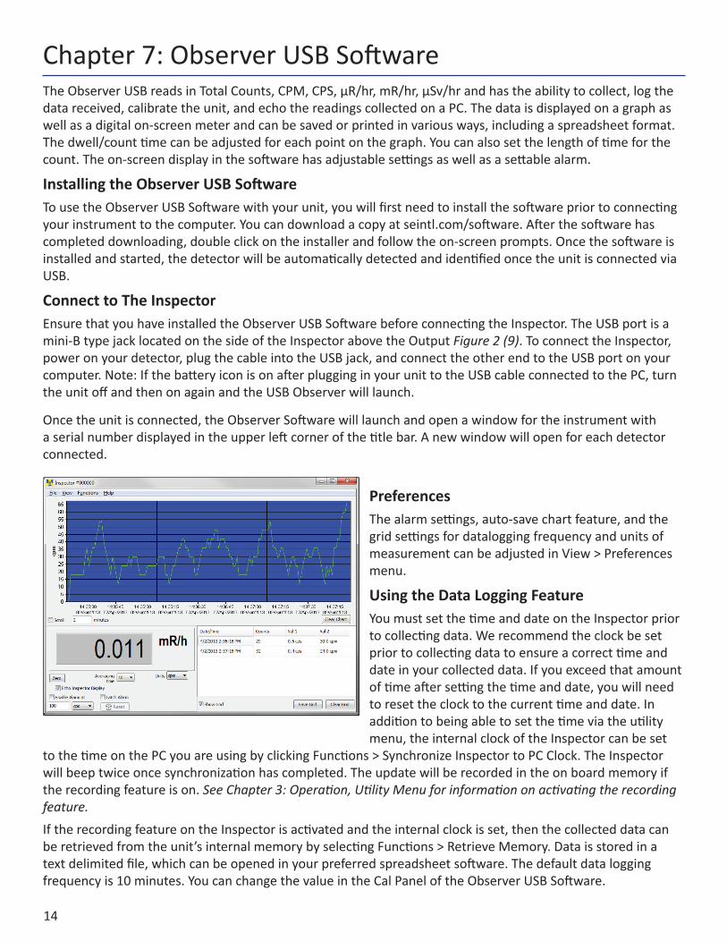
The Observer USB reads in Total Counts, CPM, CPS, µR/hr, mR/hr, µSv/hr and has the ability to collect, log the data received, calibrate the unit, and echo the readings collected on a PC. The data is displayed on a graph as well as a digital on-screen meter and can be saved or printed in various ways, including a spreadsheet format. The dwell/count time can be adjusted for each point on the graph. You can also set the length of time for the count. The on-screen display in the software has adjustable settings as well as a settable alarm.
Installing the Observer USB SoftwareTo use the Observer USB Software with your unit, you will first need to install the software prior to connecting your instrument to the computer. You can download a copy at seintl.com/software. After the software has completed downloading, double click on the installer and follow the on-screen prompts. Once the software is installed and started, the detector will be automatically detected and identified once the unit is connected via USB.
Connect to The InspectorEnsure that you have installed the Observer USB Software before connecting the Inspector. The USB port is a mini-B type jack located on the side of the Inspector above the Output Figure 2 (9). To connect the Inspector, power on your detector, plug the cable into the USB jack, and connect the other end to the USB port on your computer. Note: If the battery icon is on after plugging in your unit to the USB cable connected to the PC, turn the unit off and then on again and the USB Observer will launch.
Once the unit is connected, the Observer Software will launch and open a window for the instrument with a serial number displayed in the upper left corner of the title bar. A new window will open for each detector connected.
PreferencesThe alarm settings, auto-save chart feature, and the grid settings for datalogging frequency and units of measurement can be adjusted in View > Preferences menu.
Using the Data Logging FeatureYou must set the time and date on the Inspector prior to collecting data. We recommend the clock be set prior to collecting data to ensure a correct time and date in your collected data. If you exceed that amount of time after setting the time and date, you will need to reset the clock to the current time and date. In addition to being able to set the time via the utility menu, the internal clock of the Inspector can be set
to the time on the PC you are using by clicking Functions > Synchronize Inspector to PC Clock. The Inspector will beep twice once synchronization has completed. The update will be recorded in the on board memory if the recording feature is on. See Chapter 3: Operation, Utility Menu for information on activating the recording feature. If the recording feature on the Inspector is activated and the internal clock is set, then the collected data can be retrieved from the unit’s internal memory by selecting Functions > Retrieve Memory. Data is stored in a text delimited file, which can be opened in your preferred spreadsheet software. The default data logging frequency is 10 minutes. You can change the value in the Cal Panel of the Observer USB Software.
Chapter 7: Observer USB Software
15
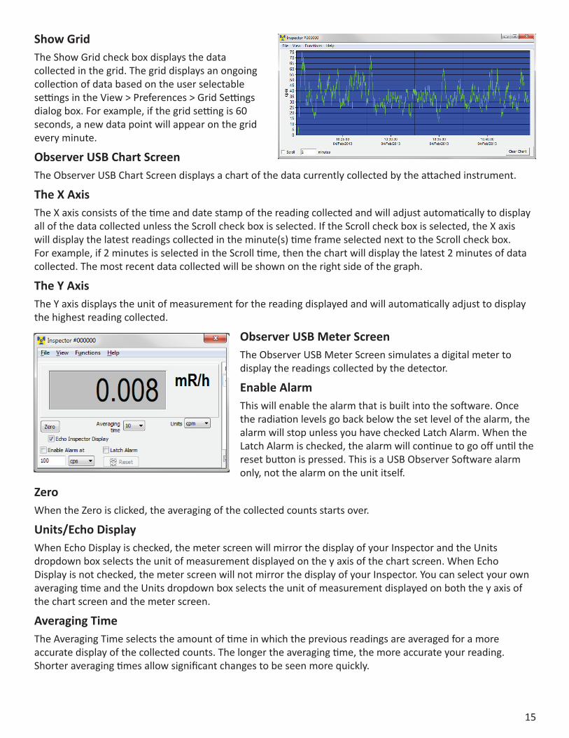
Show GridThe Show Grid check box displays the data collected in the grid. The grid displays an ongoing collection of data based on the user selectable settings in the View > Preferences > Grid Settings dialog box. For example, if the grid setting is 60 seconds, a new data point will appear on the grid every minute.
Observer USB Chart ScreenThe Observer USB Chart Screen displays a chart of the data currently collected by the attached instrument.
The X AxisThe X axis consists of the time and date stamp of the reading collected and will adjust automatically to display all of the data collected unless the Scroll check box is selected. If the Scroll check box is selected, the X axis will display the latest readings collected in the minute(s) time frame selected next to the Scroll check box. For example, if 2 minutes is selected in the Scroll time, then the chart will display the latest 2 minutes of data collected. The most recent data collected will be shown on the right side of the graph.
The Y AxisThe Y axis displays the unit of measurement for the reading displayed and will automatically adjust to display the highest reading collected.
Observer USB Meter ScreenThe Observer USB Meter Screen simulates a digital meter to display the readings collected by the detector.
Enable AlarmThis will enable the alarm that is built into the software. Once the radiation levels go back below the set level of the alarm, the alarm will stop unless you have checked Latch Alarm. When the Latch Alarm is checked, the alarm will continue to go off until the reset button is pressed. This is a USB Observer Software alarm only, not the alarm on the unit itself.
ZeroWhen the Zero is clicked, the averaging of the collected counts starts over.
Units/Echo DisplayWhen Echo Display is checked, the meter screen will mirror the display of your Inspector and the Units dropdown box selects the unit of measurement displayed on the y axis of the chart screen. When Echo Display is not checked, the meter screen will not mirror the display of your Inspector. You can select your own averaging time and the Units dropdown box selects the unit of measurement displayed on both the y axis of the chart screen and the meter screen.
Averaging TimeThe Averaging Time selects the amount of time in which the previous readings are averaged for a more accurate display of the collected counts. The longer the averaging time, the more accurate your reading. Shorter averaging times allow significant changes to be seen more quickly.
16
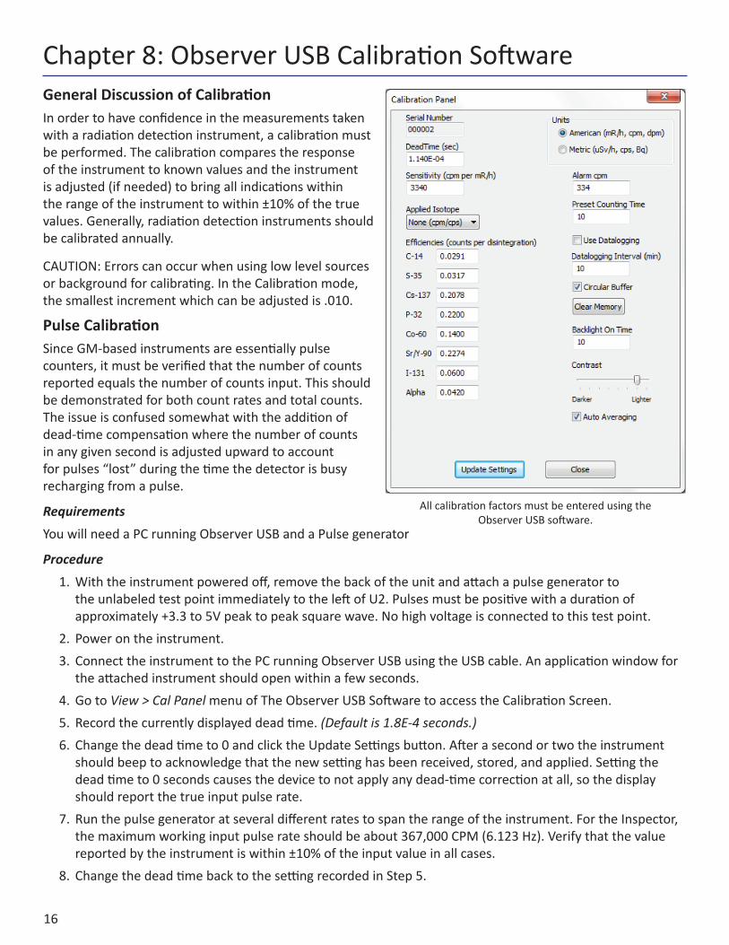
General Discussion of CalibrationIn order to have confidence in the measurements taken with a radiation detection instrument, a calibration must be performed. The calibration compares the response of the instrument to known values and the instrument is adjusted (if needed) to bring all indications within the range of the instrument to within ±10% of the true values. Generally, radiation detection instruments should be calibrated annually.
CAUTION: Errors can occur when using low level sources or background for calibrating. In the Calibration mode, the smallest increment which can be adjusted is .010.
Pulse CalibrationSince GM-based instruments are essentially pulse counters, it must be verified that the number of counts reported equals the number of counts input. This should be demonstrated for both count rates and total counts. The issue is confused somewhat with the addition of dead-time compensation where the number of counts in any given second is adjusted upward to account for pulses “lost” during the time the detector is busy recharging from a pulse.
RequirementsYou will need a PC running Observer USB and a Pulse generator
Procedure1. With the instrument powered off, remove the back of the unit and attach a pulse generator to
the unlabeled test point immediately to the left of U2. Pulses must be positive with a duration of approximately +3.3 to 5V peak to peak square wave. No high voltage is connected to this test point.
2. Power on the instrument.3. Connect the instrument to the PC running Observer USB using the USB cable. An application window for
the attached instrument should open within a few seconds.4. Go to View > Cal Panel menu of The Observer USB Software to access the Calibration Screen. 5. Record the currently displayed dead time. (Default is 1.8E-4 seconds.)6. Change the dead time to 0 and click the Update Settings button. After a second or two the instrument
should beep to acknowledge that the new setting has been received, stored, and applied. Setting the dead time to 0 seconds causes the device to not apply any dead-time correction at all, so the display should report the true input pulse rate.
7. Run the pulse generator at several different rates to span the range of the instrument. For the Inspector, the maximum working input pulse rate should be about 367,000 CPM (6.123 Hz). Verify that the value reported by the instrument is within ±10% of the input value in all cases.
8. Change the dead time back to the setting recorded in Step 5.
Chapter 8: Observer USB Calibration Software
All calibration factors must be entered using the Observer USB software.
17
Efficiency CalibrationThe Inspector can be used beyond simple detection of contamination and can also be used to determine the activity of any beta- or alpha-emitting isotopes present.
Efficiency is the ratio of events detected by the instrument to the number of decays of the particular isotope. The units are therefore counts per disintegration of c/d. Since efficiencies are generally somewhat less than one, they are often multiplied by 100 and expressed as a percentage. However, the Observer USB software requires that values not be entered as percentages. Since efficiency varies based on the energy and abundance of the particular isotope being measured, it is best to determine efficiency for the specific isotope(s) for which the activity is to be determined.
The efficiency is also affected by the size of the source and the source to detector distance. To achieve consistency, efficiencies should be determined using a point source (which means a source with an area significantly smaller than the detector entrance window) at a fixed distance from the detector face (which must be specified, but 1 cm will be assumed to be the standard).
Requirements You will need a PC running Observer USB, Calibration sources, an Inspector Wipe Test Plate (or other constant-geometry source holder to maintain sources 1 cm from the detector entrance window)
Procedure (American Units)1. Attach the Wipe Test Plate to the Inspector. Ensure the Inspector is in Total/Timer mode, displaying
COUNTS.2. Place the Inspector in the location where the efficiency calibration will be performed and take a count of
at least 10 minutes. Divide the total number counts by the acquisition time (in minutes) to calculate the background counting rate (RB) in CPM. Record this value.
3. Center the first source to be used into the Wipe Test Holder and take a count of at least 1 minute. Divide the total number of counts by the counting time (in minutes) to calculate the gross count rate (gcpm or RG).
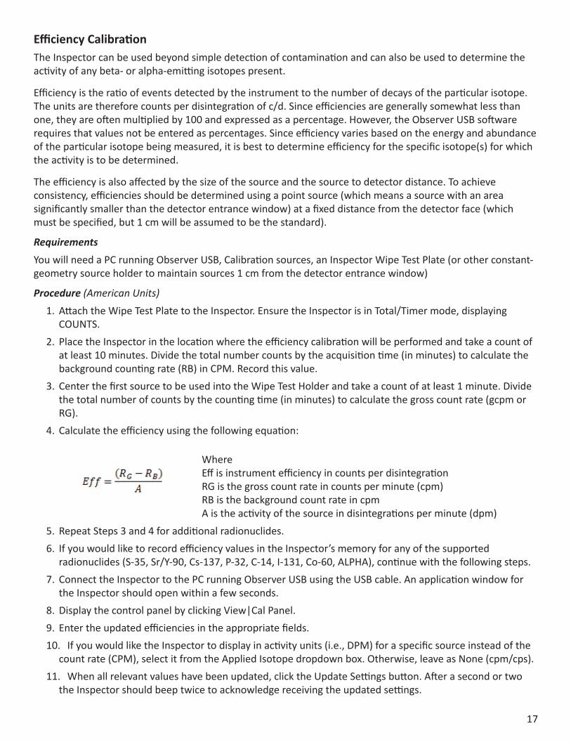
4. Calculate the efficiency using the following equation:
Where Eff is instrument efficiency in counts per disintegration RG is the gross count rate in counts per minute (cpm) RB is the background count rate in cpm A is the activity of the source in disintegrations per minute (dpm)
5. Repeat Steps 3 and 4 for additional radionuclides.6. If you would like to record efficiency values in the Inspector’s memory for any of the supported
radionuclides (S-35, Sr/Y-90, Cs-137, P-32, C-14, I-131, Co-60, ALPHA), continue with the following steps.7. Connect the Inspector to the PC running Observer USB using the USB cable. An application window for
the Inspector should open within a few seconds.8. Display the control panel by clicking View|Cal Panel.9. Enter the updated efficiencies in the appropriate fields. 10. If you would like the Inspector to display in activity units (i.e., DPM) for a specific source instead of the
count rate (CPM), select it from the Applied Isotope dropdown box. Otherwise, leave as None (cpm/cps).11. When all relevant values have been updated, click the Update Settings button. After a second or two
the Inspector should beep twice to acknowledge receiving the updated settings.
18
Procedure (Metric Units)1. Attach the Wipe Test Plate and power on the Inspector. Make sure the Inspector is in Total/Timer mode
displaying COUNTS.2. Place the Inspector in the location where the efficiency calibration will be performed and take a count of
at least 10 minutes. Multiply the acquisition time by 60 to convert it from minutes to seconds. Divide the total number counts by the acquisition time (in seconds) to calculate the background counting rate (RB) in cps. Record this value.
3. Center the first source to be used into the Wipe Test Holder and take a count of at least 1 minute. Divide the total number of counts by the counting time (in seconds) to calculate the gross count rate (gcps or RG).
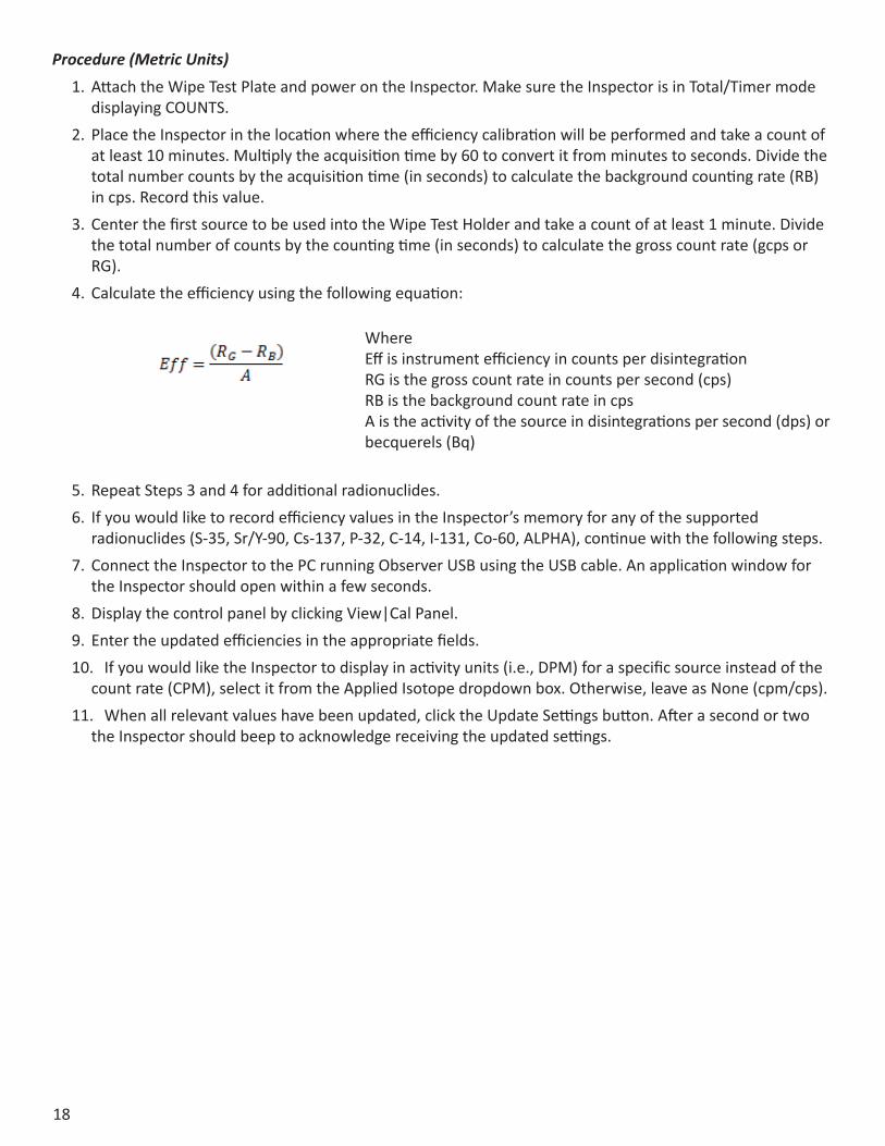
4. Calculate the efficiency using the following equation:
Where Eff is instrument efficiency in counts per disintegration RG is the gross count rate in counts per second (cps) RB is the background count rate in cps A is the activity of the source in disintegrations per second (dps) or becquerels (Bq)
5. Repeat Steps 3 and 4 for additional radionuclides.6. If you would like to record efficiency values in the Inspector’s memory for any of the supported
radionuclides (S-35, Sr/Y-90, Cs-137, P-32, C-14, I-131, Co-60, ALPHA), continue with the following steps.7. Connect the Inspector to the PC running Observer USB using the USB cable. An application window for
the Inspector should open within a few seconds.8. Display the control panel by clicking View|Cal Panel.9. Enter the updated efficiencies in the appropriate fields.10. If you would like the Inspector to display in activity units (i.e., DPM) for a specific source instead of the
count rate (CPM), select it from the Applied Isotope dropdown box. Otherwise, leave as None (cpm/cps).11. When all relevant values have been updated, click the Update Settings button. After a second or two
the Inspector should beep to acknowledge receiving the updated settings.
19
Exposure Rate CalibrationAn exposure rate calibration correlates the number of counts in a given time to the exposure rate present in that field. This is in many ways similar to efficiency but we refer to it in this case as gamma sensitivity. Although it is possible to express this value in several different units, the Inspector uses a formula of CPM/mR/hr (counts per minute per milliroentgen per hour).
The instrument is placed in gamma radiation fields of different (but known) intensities that span the working range of the instrument, and the settings are adjusted (if needed) such that all measurements are within ±10% of the true value. The relevant settings include both the sensitivity and the dead time.
The gamma field is usually generated by a relatively strong Cs-137 source. Exposure rates are calculated to the center of the detector’s volume.
RequirementsYou will need a PC running Observer USB and a Gamma calibration range
Procedure1. Power on the instrument.2. Connect the instrument to the PC running Observer USB using the USB cable. An application window for
the attached instrument should open within a few seconds.3. Display the calibration panel by clicking View|Cal Panel.4. Record the displayed values for Dead Time and Sensitivity.5. Begin checking the instrument’s Sensitivity. Place the instrument in a relatively low field, approximately 5
mR/hr, and allow it 30 seconds or so to stabilize.6. If the indicated response is off by more than 3% at this level, adjust the Sensitivity to a lower value if the
instrument is reading too low, or to a higher value if the instrument is reading too high. After changing the value on the Calibration Panel, click the Update Settings button. After a second or two the instrument will beep to indicate that the new value has been received.
7. Repeat Step 5 as needed to bring the instrument indication as close as possible to the true value.8. Next, expose the instrument to a field near the top of its range of 100 mR/hr. Allow the reading to
stabilize for at least 30 seconds. In the preferences tab, you can adjust the time in the gird to show a selected average count.
9. If the indicated response is off by more than 10%, adjust the Dead Time to a lower value if the instrument reading is too low, or to a higher value if the instrument reading is too high. After changing the value on the Calibration Panel, click the Update Settings button. After a second or two the instrument will beep twice to indicate that the new value has been received.
10. Repeat step 9 as needed to bring the instrument’s indication within ±10% of the true value.11. Once the values for Sensitivity and Dead Time have been verified to be correct, expose the instrument
to a series of values spanning the range of the instrument. All indications should be within ±10% of the true value.

20
Built in Isotope EfficienciesThe Inspector has a number of built in efficiencies for specific isotopes. If you know the isotope being surveyed, then you can select one of the pre-programmed isotope efficiencies to calculate the activity of your known source. The activity (DPM and Bq) is different from the rates of exposure (mR/hr, µSv/hr, CPM, and CPS). Activity is the number of disintegrations of a radioactive substance in a given unit of time, which is specific to the isotope being detected. The efficiencies programmed into the Inspector USB are based on the geometry of our wipe test plate, which places samples 1cm from the end window of the detector. Caution: Do not use the built in efficiencies unless you are surveying a known isotope, as doing so will give you inaccurate results.
DecayWhen an atom emits an alpha or beta particle or a gamma ray, it becomes a different type of atom. Radioactive substances may go through several stages of decay before they change into a stable, or non-ionizing, form. For example; U-238 has 14 different stages of decay before it stabilizes.
An element may have several forms or isotopes. A radioactive isotope of an element may be called a radioisotope. However, the more correct term is radionuclide.
Selecting a Built-In Isotope EfficiencyEnter the Utility Menu and scroll to the USE menu item and press SET on the end panel of the unit to select the isotope efficiency you want to use for your survey. For example, if you know you are surveying Iodine-131, then you would select I131 from the menu. Once you have selected the cooresponding isotope, press the SET button to select it. Press SET again to begin normal operation of the Inspector.
You can select from any of the following isotope efficiencies built into the Inspector: 35Sulfur (S-35), 90Strontium (Sr/y-90), 137Cesium (Cs-137), 32Phosphorus (P-32), 14Carbon (C-14), 131Iodine (I-131), 60Cobalt (Co-60), and Alpha.
Selecting Between DPM and BqEnter the Utility Menu and scroll to the UNIT menu item and press SET on the end panel of the unit to change the units of measurement between DPM (when mR/hr and CPM are selected) and Bq (when µSv/hr and CPS are selected).
Chapter 9: Built in Isotope Efficiencies
21
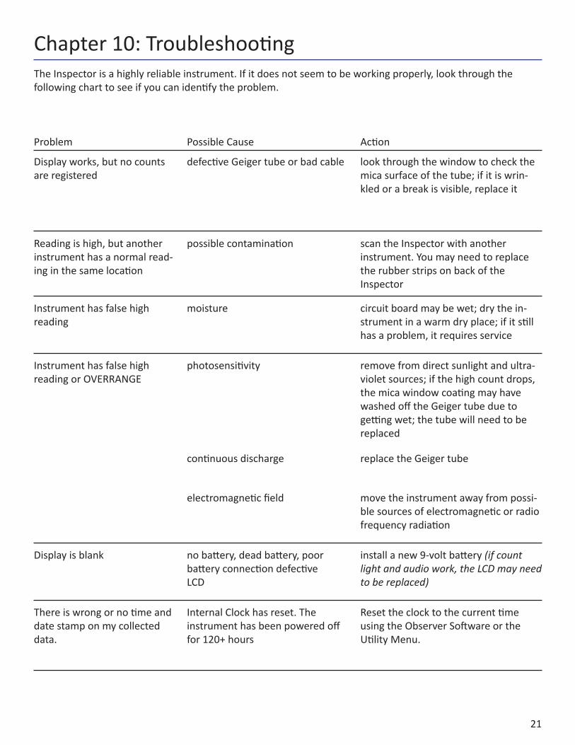
The Inspector is a highly reliable instrument. If it does not seem to be working properly, look through the following chart to see if you can identify the problem.
Chapter 10: Troubleshooting
Problem Possible Cause Action
Display works, but no counts are registered
defective Geiger tube or bad cable look through the window to check the mica surface of the tube; if it is wrin-kled or a break is visible, replace it
Reading is high, but another instrument has a normal read-ing in the same location
possible contamination scan the Inspector with another instrument. You may need to replace the rubber strips on back of the Inspector
Instrument has false high reading
moisture circuit board may be wet; dry the in-strument in a warm dry place; if it still has a problem, it requires service
Instrument has false high reading or OVERRANGE
photosensitivity remove from direct sunlight and ultra-violet sources; if the high count drops, the mica window coating may have washed off the Geiger tube due to getting wet; the tube will need to be replaced
continuous discharge replace the Geiger tube
electromagnetic field move the instrument away from possi-ble sources of electromagnetic or radio frequency radiation
Display is blank no battery, dead battery, poor battery connection defectiveLCD
install a new 9-volt battery (if count light and audio work, the LCD may need to be replaced)
There is wrong or no time and date stamp on my collected data.
Internal Clock has reset. The instrument has been powered off for 120+ hours
Reset the clock to the current time using the Observer Software or the Utility Menu.

22
Chapter 11: Basics of Taking MeasurementsThe Inspector will not detect neutron, microwave, RF (radio frequency), laser, infrared, or ultraviolet radiation. All of our instruments are most accurate for Cesium-137 and isotopes of similar energies. Some isotopes detected relatively well by most Geiger counters are Cobalt-60, Technicium-99M, Phosphorous-32, Strontium-90, and many forms of Radium, Plutonium, Uranium, and Thorium.
Some forms of radiation are very difficult or impossible for a Geiger tube to detect. Tritium, for example, is a by-product of a nuclear reactor and is used in research. The beta emissions from Tritium are so weak that there are very few instruments that are capable of detecting it. More sophisticated equipment is needed for the measurement of environmental samples, such as radioactivity in milk, produce, soil, etc., unless you are looking for gross contamination.
The radiation from some isotopes can cause a Geiger tube to overexcite and indicate a higher level of radiation than is actually present. Americium 241 is an example of this phenomenon. Americium 241 is used in some smoke detectors and many different types of industrial density and flow meters.
Unless you know exactly what you are measuring and understand the limitations of detection instruments, it is possible to draw misleading conclusions from your readings. We design our instruments to detect the broadest range of ionizing radiation possible and still be affordable. The full spectrum of ionizing radiation cannot be measured by one single instrument. Everyone agrees that radioactive materials can be dangerous. We encourage you to seek out other sources of information.
How to Detect Background RadiationTo see what the background radiation is in your area, simply turn the instrument on and, after the 30 second start up beep, the general background radiation will be displayed.
How To Survey a SurfaceWhen surveying a surface, such as a counter top, you will need to hold the Inspector about 1-2 centimeters from the surface while moving the unit horizontally across the survey area at a rate of 2 inches per second.
How to Perform a General SurveyA general survey would be used to find a potential source. For example, if you are looking for a potential source in a pile of scrap, the Inspector will typically detect about 2 feet into a pile. It is easier to find a source when the Inspector is set to Fast Response mode. However, even if the Inspector is in Auto-Averaging mode, the audio clicks that indicate a count should be a sufficient indicator if a potential source is present. To find the source, slowly move the Inspector in the direction of the higher readings or clicks until the potential source is found.
23
Geiger counters can detect the four main types of ionizing radiation: alpha, beta, gamma, and x-rays. Some detect only gamma and x-rays. Our instruments are calibrated to Cesium 137, but also serve as excellent indicators for many other sources of ionizing radiation. Gamma and x-rays are measured in milliroentgens per hour (mR/hr), microsieverts (µSv/hr), or millisieverts (mSv/hr). Alpha and beta are measured in counts per minute (CPM) or counts per second (CPS).
The window of the GM tube is very thin mica. This mica window is protected by a screen. Some levels of alpha, low energy beta, gamma, and x-rays that cannot penetrate the plastic case or the side of the tube can be sensed through the window.
Try not to touch the instrument to any suspected radioactive substance.
Although some beta and most gamma radiation can go through protective gear, try to avoid skin contamination and ingestion. When you leave a radioactive area, remove any protective outerwear and dispose of it properly. If you think you have been contaminated, as an additional precaution, shower and consult a physician.
How to Determine Alpha, Beta, or Gamma source.To determine whether the radiation detected is alpha, beta, or gamma, hold the instrument toward the source.
Alpha: If there is no indication through the back of the case (the side of the tube), position the window close to but not touching the source. If there is an indication, it is alpha, beta, or low energy gamma. If a sheet of paper placed between the window and the source stops the indication, it is most likely alpha. To avoid particles falling into the instrument, do not hold the source above the window.
Beta: Place a piece of aluminum about 1/8 inch (3 mm) thick between the instrument and the source. If the indication stops, decreases, or changes, it is most likely beta radiation. Most common isotopes emit both beta and gamma radiation. This is why the indication would decrease or change but not stop.
The non-occupational dose limits set by the government is 100 mR above background annually.
It is up to the individual to decide what a safe radiation level is. It will be different depending on the individual and their knowledge of radiation and its affects. Radiation levels will vary according to location and circumstances. As an example; if your background level is 25 CPM (counts per minute) where you live, when you fly in an airplane at 30,000 feet your rate meter may measure 200 CPM (.2 mR) for 2 to 5 hours. That is 8 times your normal background radiation on the ground, but it is only for a limited amount of time.
When measuring radiation in an emergency response situation, it is good to have something to compare your readings to. Taking a background radiation level reading in your area before a radiation event will help you determine if you have an elevated level of radiation and whether or not to stay in that location. Background radiation is naturally occurring radiation that is always present. It includes high energy gamma rays from the sun and outer space and alpha, beta, gamma radiation emitted from elements in the earth. Using a rate meter, you can determine your normal background radiation levels.
Gamma and X-Rays: If there is an indication of radioactivity, it is most likely gamma or high energy beta. Low energy gamma and x-rays (10-40 keV) cannot penetrate the side of the GM tube, but may be detected through the window.
If you perform the alpha/beta test above and there is no change or only a very slight change in the indication, the source is emitting primarily gamma radiation.
24
Radiation Measurement UnitsSeveral different units are used to measure radiation, exposure and dosage.
Roentgen is the amount of X-radiation or gamma radiation that produces one electrostatic unit of charge in one cc of dry air at 0° C and 760 mm of mercury atmospheric pressure. One thousand milliroentgen (1,000 mR)= 1R. The Inspector displays in milliroentgens per hour (mR/hr).
Rad is the unit of exposure to ionizing radiation equal to an energy of 100 ergs per gram of irradiated material. This is approximately equal to 1.07 roentgen.
Rem is the dosage received from exposure to a rad. It is the number of rads multiplied by the quality factor of the particular source of radiation. The rem and millirem are the most commonly-used measurement units of radiation dose in the U.S. 1 rem= 1 rad.
Sievert is the standard international measurement of dose. One sievert is equivalent to one hundred rems. A microsievert (μSv) is one millionth of a sievert. A unit of dose equivalent. 1 Sv= 100 roentgens, 10 µSv/hr = 1 milliroentgen/hr.
Curie is the amount of radioactive material that decays at the rate of 37 billion disintegrations per second, approximately the decay rate of one gram of radium. Microcuries (millionths of a curie) and picocuries (trillionths of a curie) are also often used as units of measurement.
Becquerel (Bq) is defined as the activity of a quantity of radioactive material in which one nucleus decays per second. 1 dps (one disintegration per second).
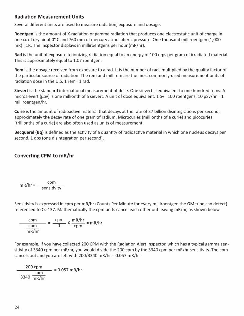
Converting CPM to mR/hr
mR/hr = cpmsensitivity
Sensitivity is expressed in cpm per mR/hr (Counts Per Minute for every milliroentgen the GM tube can detect) referenced to Cs-137. Mathematically the cpm units cancel each other out leaving mR/hr, as shown below.
For example, if you have collected 200 CPM with the Radiation Alert Inspector, which has a typical gamma sen-sitivity of 3340 cpm per mR/hr, you would divide the 200 cpm by the 3340 cpm per mR/hr sensitivity. The cpm cancels out and you are left with 200/3340 mR/hr = 0.057 mR/hr
= cpmcpm
mR/hr
cpm1 XmR/hr
cpm = mR/hr
200 cpmcpm
mR/hr
= 0.057 mR/hr3340
25
Background RadiationNaturally occurring radiation is always present, it includes high energy gamma rays and particles from the sun and outer space and alpha, beta, and gamma radiation emitted from elements in the earth.
CPM (counts per minute)The unit of measurement usually used to measure alpha and beta radiation.
IonAn atomic particle, atom, or molecule that has acquired an electrical charge, either positive or negative, by gaining or losing electrons.
IonizationThe process by which neutral atoms of molecules are divided into pairs of oppositely charged particles known as ions.
Ionizing RadiationRadiation capable of producing ionization by breaking up atoms or molecules into charged particles called ions.
RadiationThe emission and propagation of energy through space or through matter in the form of particles or waves.
RadionuclideThe naturally occurring or artificially produced radioactive form of an element.
DecayWhen an atom emits an alpha or beta particle or a gamma ray, it becomes a different type of atom. Radioactive substances may go through several stages of decay before they change into a stable, or non-ionizing, form. For example; U-238 has 14 different stages of decay before it stabilizes. An element may have several forms, or isotopes. A radioactive isotope of an element may be called a radioisotope. However, the more correct term is radionuclide.
Half-lifeEach radionuclide has a characteristic half-life, which is the time required for half of a quantity of the material to decay.
Chapter 12: Glossary of Common Terms
26
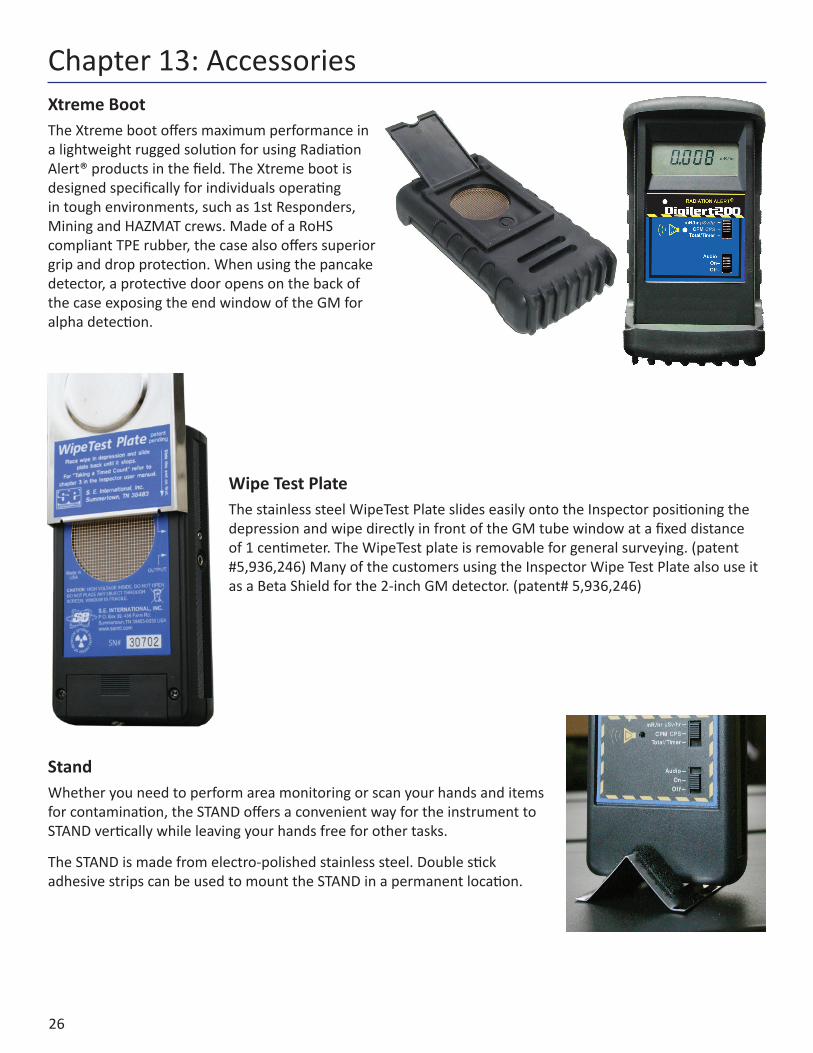
Xtreme BootThe Xtreme boot offers maximum performance in a lightweight rugged solution for using Radiation Alert® products in the field. The Xtreme boot is designed specifically for individuals operating in tough environments, such as 1st Responders, Mining and HAZMAT crews. Made of a RoHS compliant TPE rubber, the case also offers superior grip and drop protection. When using the pancake detector, a protective door opens on the back of the case exposing the end window of the GM for alpha detection.
Wipe Test PlateThe stainless steel WipeTest Plate slides easily onto the Inspector positioning the depression and wipe directly in front of the GM tube window at a fixed distance of 1 centimeter. The WipeTest plate is removable for general surveying. (patent #5,936,246) Many of the customers using the Inspector Wipe Test Plate also use it as a Beta Shield for the 2-inch GM detector. (patent# 5,936,246)
StandWhether you need to perform area monitoring or scan your hands and items for contamination, the STAND offers a convenient way for the instrument to STAND vertically while leaving your hands free for other tasks.
The STAND is made from electro-polished stainless steel. Double stick adhesive strips can be used to mount the STAND in a permanent location.
Chapter 13: Accessories
27
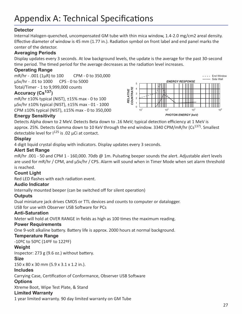
DetectorInternal Halogen-quenched, uncompensated GM tube with thin mica window, 1.4-2.0 mg/cm2 areal density. Effective diameter of window is 45 mm (1.77 in.). Radiation symbol on front label and end panel marks the center of the detector.Averaging PeriodsDisplay updates every 3 seconds. At low background levels, the update is the average for the past 30-second time period. The timed period for the average decreases as the radiation level increases.Operating RangemR/hr - .001 (1µR) to 100 CPM - 0 to 350,000µSv/hr - .01 to 1000 CPS - 0 to 5000Total/Timer - 1 to 9,999,000 countsAccuracy (Cs137)mR/hr ±10% typical (NIST), ±15% max - 0 to 100µSv/hr ±10% typical (NIST), ±15% max - 01 - 1000CPM ±10% typical (NIST), ±15% max - 0 to 350,000 Energy SensitivityDetects Alpha down to 2 MeV. Detects Beta down to .16 MeV; typical detection efficiency at 1 MeV is approx. 25%. Detects Gamma down to 10 KeV through the end window. 3340 CPM/mR/hr (Cs137). Smallest detectable level for I125 is .02 µCi at contact.Display4 digit liquid crystal display with indicators. Display updates every 3 seconds.Alert Set RangemR/hr .001 - 50 and CPM 1 - 160,000. 70db @ 1m. Pulsating beeper sounds the alert. Adjustable alert levels are used for mR/hr / CPM, and µSv/hr / CPS. Alarm will sound when in Timer Mode when set alarm threshold is reached.Count LightRed LED flashes with each radiation event.Audio IndicatorInternally mounted beeper (can be switched off for silent operation)OutputsDual miniature jack drives CMOS or TTL devices and counts to computer or datalogger. USB for use with Observer USB Software for PCsAnti-SaturationMeter will hold at OVER RANGE in fields as high as 100 times the maximum reading.Power RequirementsOne 9-volt alkaline battery. Battery life is approx. 2000 hours at normal background.Temperature Range-10ºC to 50ºC (14ºF to 122ºF)WeightInspector: 273 g (9.6 oz.) without battery.Size150 x 80 x 30 mm (5.9 x 3.1 x 1.2 in.).IncludesCarrying Case, Certification of Conformance, Observer USB SoftwareOptionsXtreme Boot, Wipe Test Plate, & StandLimited Warranty1 year limited warranty. 90 day limited warranty on GM Tube
Appendix A: Technical Specifications
5
4
3
2
10
101 102 103 104
ENERGY RESPONSE
REL
ATI
VE
PHOTON ENERGY (keV)
CO
UN
TRA
TE
End WindowSide Wall
28
WARRANTOR: S.E. International, Inc., P.O. Box 39, 436 Farm Road, Summertown, TN 38483-0039, USA, (931) 964-3561
ELEMENTS OF WARRANTY: S.E. International, Inc., warrants for 90 days the Geiger-Mueller tube and for one year all materials and craftsmanship in this product to be free from all defects with only the limitations set out below.
WARRANTY DURATION: The warranty shall terminate and be of no further effect one year (90 days on the GM tube) after the original date of purchase of the product or at the time the product is: a) damaged or not maintained as is reasonable or necessary, b) modified, c) repaired by someone other than the warrantor for a defect or malfunction covered by this Warranty, d) contaminated with radioactive materials, or e) used in a manner or purpose for which the instrument was not intended or contrary to S.E. International, Inc.’s written instructions. This warranty does not apply to any product subjected to corrosive elements, misuse, abuse, or neglect.
STATEMENT OF REMEDY: In the event that the product does not conform to the warranty at any time while this warranty is effective, the Warrantor will repair the defect and return the instrument to you prepaid, without charge for parts or labor.
NOTE: While the product will be remedied under this warranty without charge, this warranty does not cover or provide for the reimbursement or payment of incidental or consequential damages arising from the use of or the inability to use this product. The liability of the company arising out of the supplying of this instrument, or its use, whether on warranties or otherwise, shall not in any case exceed the cost of correcting defects in the instrument, and after the said one year (90 days on the tube) period all such liability shall terminate. Any implied warranty is limited to the duration of the written warranty.
PROCEDURE FOR OBTAINING PERFORMANCE OF WARRANTY: In the event that the product does not conform to this warranty, please write or call to the address above. S.E. International, Inc. will not accept contaminated instruments for calibration or repair under warranty or otherwise.
NOTE: Before using this instrument, the user must determine the suitability of the product for his or her intended use.
Appendix B: Limited Warranty
29
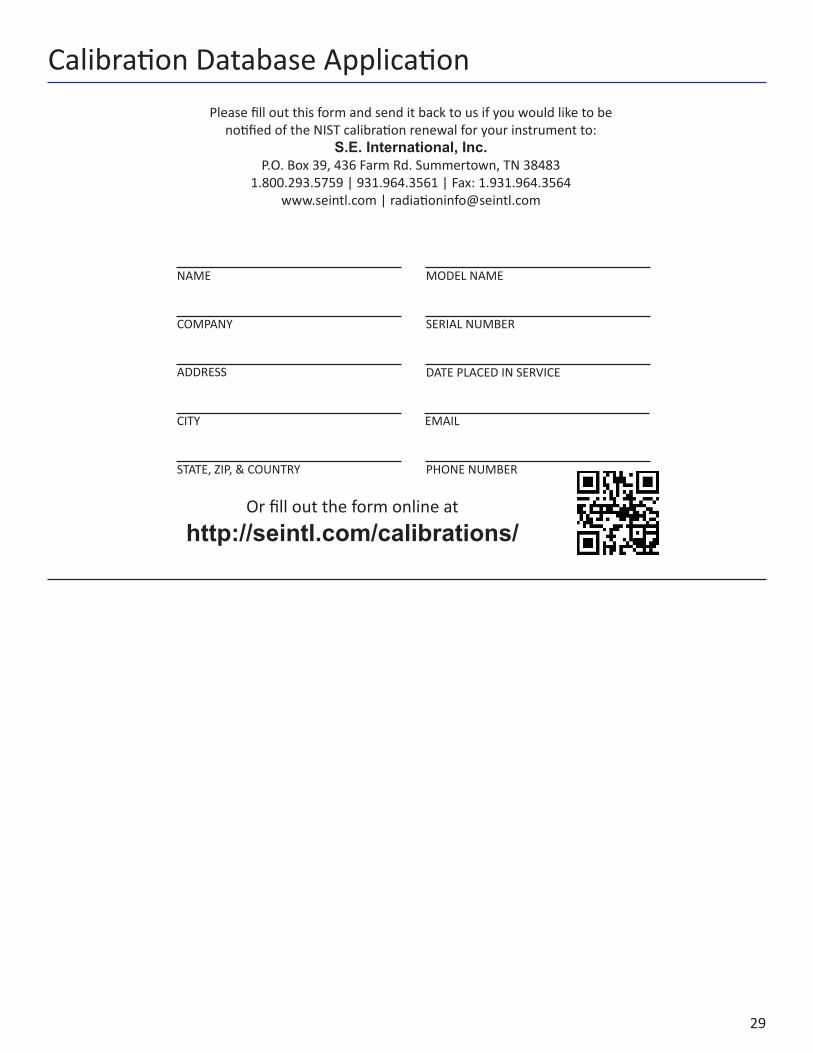
Or fill out the form online at http://seintl.com/calibrations/
NAME MODEL NAME
COMPANY SERIAL NUMBER
ADDRESS
CITY
STATE, ZIP, & COUNTRY PHONE NUMBER
Please fill out this form and send it back to us if you would like to be notified of the NIST calibration renewal for your instrument to:
S.E. International, Inc.P.O. Box 39, 436 Farm Rd. Summertown, TN 38483
1.800.293.5759 | 931.964.3561 | Fax: 1.931.964.3564www.seintl.com | [email protected]
DATE PLACED IN SERVICE
Calibration Database Application