TM 9-3990-260-14&P
307
TM 9-3990-260-14&P TECHNICAL MANUAL OPERATOR’S, UNIT, DIRECT SUPPORT AND GENERAL SUPPORT MAINTENANCE MANUAL (INCLUDING REPAIR PARTS AND SPECIAL TOOLS LIST) CONTAINER ROLL-IN/OUT PLATFORM (CROP) MODEL M3 NSN 3990-01-442-2751 CONTAINER ROLL-IN/OUT PLATFORM (CROP) MODEL M3A1 NSN 3990-01-450-5671 DISTRIBUTION RESTRICTION Approved for public release; Distribution is unlimited HEADQUARTERS, DEPARTMENT OF THE ARMY 27 JULY 2001 INTRODUCTION (M3 CROP) 1-1 OPERATING INSTRUCTIONS (M3 CROP) 2-1 OPERATOR MAINTENANCE INSTRUCTIONS 3-1 (M3 CROP) UNIT MAINTENANCE INSTRUCTIONS (M3 CROP) 4-1 DIRECT SUPPORT MAINTENANCE (M3 CROP) 5-1 INTRODUCTION (M3A1 CROP) 6-1 OPERATING INSTRUCTIONS (M3A1 CROP) 7-1 OPERATOR MAINTENANCE INSTRUCTIONS 8-1 (M3A1 CROP) UNIT MAINTENANCE INSTRUCTIONS (M3A1 CROP) 9-1 DIRECT SUPPORT MAINTENANCE (M3A1 CROP) 10-1 MAINTENANCE ALLOCATION CHART (MAC) B-1 COMPONENTS OF END ITEM (COEI) & BASIC C-1 ISSUE ITEMS (BII) LISTS EXPENDABLE AND DURABLE ITEMS LIST E-1 REPAIR PARTS AND SPECIAL TOOLS LIST F-1 ILLUSTRATED LIST OF MANUFACTURED ITEMS G-1 MANDATORY REPLACEMENT PARTS LIST H-1 TOOL IDENTIFICATION LIST I-1 LUBRICATION INSTRUCTIONS (M3 CROP) J-1 LUBRICATION INSTRUCTIONS (M3A1 CROP) K-1 ADDITIONAL AUTHORIZATION LIST (AAL) D-1
Transcript of TM 9-3990-260-14&P

TM 9-3990-260-14&P
TECHNICAL MANUAL
OPERATOR’S, UNIT, DIRECT SUPPORT AND GENERAL SUPPORT MAINTENANCE MANUAL
(INCLUDING REPAIR PARTS AND SPECIAL TOOLS LIST)
CONTAINER ROLL-IN/OUTPLATFORM (CROP) MODEL M3
NSN 3990-01-442-2751
CONTAINER ROLL-IN/OUTPLATFORM (CROP) MODEL M3A1
NSN 3990-01-450-5671
DISTRIBUTION RESTRICTION Approved for public release;
Distribution is unlimited
HEADQUARTERS, DEPARTMENT OF THE ARMY27 JULY 2001
INTRODUCTION (M3 CROP) 1-1
OPERATING INSTRUCTIONS (M3 CROP) 2-1
OPERATOR MAINTENANCE INSTRUCTIONS 3-1(M3 CROP)
UNIT MAINTENANCE INSTRUCTIONS (M3 CROP) 4-1
DIRECT SUPPORT MAINTENANCE (M3 CROP) 5-1
INTRODUCTION (M3A1 CROP) 6-1
OPERATING INSTRUCTIONS (M3A1 CROP) 7-1
OPERATOR MAINTENANCE INSTRUCTIONS 8-1(M3A1 CROP)
UNIT MAINTENANCE INSTRUCTIONS (M3A1 CROP) 9-1
DIRECT SUPPORT MAINTENANCE (M3A1 CROP) 10-1
MAINTENANCE ALLOCATION CHART (MAC) B-1
COMPONENTS OF END ITEM (COEI) & BASIC C-1ISSUE ITEMS (BII) LISTS
EXPENDABLE AND DURABLE ITEMS LIST E-1
REPAIR PARTS AND SPECIAL TOOLS LIST F-1
ILLUSTRATED LIST OF MANUFACTURED ITEMS G-1
MANDATORY REPLACEMENT PARTS LIST H-1
TOOL IDENTIFICATION LIST I-1
LUBRICATION INSTRUCTIONS (M3 CROP) J-1
LUBRICATION INSTRUCTIONS (M3A1 CROP) K-1
ADDITIONAL AUTHORIZATION LIST (AAL) D-1


TM 9-3990-260-14&P
Change 1 a
Bail bar may have metal slivers or sharp edges. Wear gloves if handling or injury to per-sonnel could result.
• M3 CROP End structure assembly weighs 370 lbs (168 kg). Raising and loweringmust be conducted on level ground. Use the aid of a suitable lifting device when rais-ing or lowering end structure assembly to prevent serious injury or death to personnel.
• Ensure that at least one crewmember holds the end structure assembly in the uprightposition until it is secured with the front and rear pins.
• CROPs must be empty when stacked. Attempting to stack loaded CROPs could causeserious injury or death to personnel.
• Always lift a stack of CROPs by connecting to the bottom CROP, either by overheadMHE or forklift. Failure to comply may result in severe injury to personnel or dam-age to equipment.
Ensure web straps are wrapped a minimum of three times around ratchet of web strap.Failure to comply may result in web strap being released and CROP may fall, causingsevere injury or death to personnel.
M3 CROP weighs 3,800 lbs (1,724 kg) and the M3 CROP (S/N SC09001 and up) weighs3,730 lbs (1,692 kg). Ensure all personnel stand clear of CROP when CROP is beingmoved. Failure to comply may result in severe injury or death to personnel.
ALWAYS use work gloves when loading/unloading or stacking/unstacking CROP assem-blies. Failure to follow the warning may result in serious injury to personnel.

TM 9-3990-260-14&P
b Change 1
Always use a ground guide when transferring CROP loads from PLS trucks to trailers, toadvise the driver of any load binding problems or of possible truck to trailer separation.Failure to follow the warning may result in damage to equipment or serious injury to per-sonnel.
• Ensure web traps are wrapped a minimum of three times around ratchet of web strap.Failure to comply may result in web strap being released and CROP may fall, causingsevere injury or death to personnel.
• One M3 CROP weighs 3,800 lbs (1,724 kg) and the M3 CROP (S/N SC09001 andup) weighs 3,730 lbs (1,692 kg). Six M3 CROPs weigh 22,800 lbs (10,342 kg) andsix M3 CROPs (S/N SC09001 and up) weigh 22,380 lbs (10,152 kg). Gross weight ofa fully loaded CROP is 36,250 lbs (16,443 kg). Ensure all personnel stand clear ofCROPs when being moved. Failure to comply may result in severe injury or death topersonnel.
• Always lift a stack of CROPs by connecting to the bottom CROP. Failure to complymay result in severe injury to personnel or damage to equipment.
• One M3 CROP weighs 3,800 lbs (1,724 kg) and the M3 CROP (S/N SC09001 andup) weighs 3,730 lbs (1,692 kg). Six M3 CROPs weigh 22,800 lbs (10,342 kg) andsix M3 CROPs (S/N SC09001 and up) weigh 22,380 lbs (10,152 kg). Ensure all per-sonnel stand clear of CROP when CROP is being moved. Failure to comply mayresult in severe injury or death to personnel.
• Always lift a stack of CROPs by connecting lifting device to the bottom CROP. Fail-ure to comply may result in severe injury to personnel or damage to equipment.
• Attempting to load stack of CROPs or a loaded CROP in ISO container requires ex-treme care to prevent damage to equipment. Clearance between the ceiling of the ISOcontainer and top of the load and inside walls of the ISO container and each side ofCROP is unusually close, requiring at least one ground guide to assist during the dif-ficult insertion procedure.
• Ensure web straps securing stack of CROPs are removed prior to insertion into anISO container. Failure to comply may result in damage to web straps during insertionprocedure.
Do not stand between the CROP and the ISO container. Ensure all personnel stand clear ofCROP when CROP is being moved. Failure to comply may result in severe injury or deathto personnel.

TM 9-3990-260-14&P
Change 1 c
Closely observe stack of CROPs during this part of offloading to ensure it does not come incontact with top of ISO container door opening or inside walls of ISO container. Failure toexercise extreme caution during insertion may result in damage to ISO container or CROP.
• Do not stand between the CROPs and the ISO container Ensure all personnel standclear of CROP when CROP is being moved. Failure to comply may result in severeinjury or death to personnel.
• Exercise extreme caution to prevent contact between the PLS truck hook arm and topof ISO container door opening. Failure to comply can result in damage to ISO con-tainer door frame and/or door latches.
• Forklift must be capable of lifting gross weight of loaded CROP. Failure to complymay result in damage to equipment or severe injury or death to personnel. Do notdrive a forklift on the CROP deck; doing so exceeds point load capability of the deck.
• One M3 CROP weighs 3,800 lbs (1,724 kg) and the M3 CROP (S/N SC09001 andup) weighs 3,730 lbs (1,692 kg). Six M3 CROPs weigh 22,800 lbs (10,342 kg) andsix M3 CROPs (S/N SC09001 and up) weigh 22,380 lbs (10,152 kg). Gross weight ofa fully loaded CROP is 36,250 lbs (16,443 kg). Ensure all personnel stand clearof CROP when CROP is being moved. Failure to comply may result in severe injuryor death to personnel.
• Attempting to load a CROP in ISO container requires extreme care to prevent dam-age to equipment. Clearance between the inside of ISO container and each side ofCROP is unusually close.
• Always lift a stack of CROPs by connecting to the bottom CROP. Failure to complymay result in severe injury to personnel or damage to equipment.
• Forklifts are required to have forks a minimum of 68 in. (173 cm) in length. Failure tocomply may result in severe injury to personnel or damage to equipment.

TM 9-3990-260-14&P
d
• Ensure forklift tines are horizontal or pointed slightly downward to ensure they do notcontact crossmembers or the underside of the deck when the tines are being insertedunder the CROP or when the CROP is being lifted from the front. Prior to lifting,ensure the tines are in full contact with the front beam and are not contacting cross-members. Failure to comply may result in damage to equipment.
• Ensure forklift tines are positioned to the outside of the CROP main beams, betweenthe main beams and the multipurpose provisions. Do not attempt to lift front of CROPwith forklift tines on the inside of main beams. Failure to comply may result in dam-age to equipment.
• Exercise extreme caution to ensure the CROP is properly aligned to be inserted intothe ISO container. The CROP is designed with less than 1/2 inch clearance on eitherside between the CROP and ISO container door frame. Failure to comply may resultin damage to equipment.
• Ensure forklift tines are horizontal or pointed slightly downward to ensure they do notcontact crossmembers or the underside of the deck when the tines are being insertedunder the CROP or when the CROP is being lifted from the front. Prior to lifting,ensure the tines are in full contact with the front beam and are not contacting cross-members. Failure to comply may result in damage to equipment.
• Ensure forklift tines are positioned to the outside of the CROP main beams, betweenthe main beams and the multipurpose provisions. Do not attempt to lift front of CROPwith forklift tines on the inside of main beams. Failure to comply may result in dam-age to equipment.

TM 9-3990-260-14&P
Change 1 e
Solvent cleaning compound (MIL-PRF-680) can cause eye and skin irritation. Wear pro-tective rubber gloves and chemical splash goggles or faceshield to avoid skin or eye con-tact. Use in a well ventilated area. First aid for skin contact: remove any contaminatedclothing and wash skin thoroughly with soap and water. First aid for eye contact: flush withwater for 15 minutes or until irritation subsides. If irritation persists, call a physician. Ifovercome by vapors, move from exposed area and call a physician. In case of ingestion, donot induce vomiting, call a physician immediately.
• End structure assembly dead weight is beyond two-man lift limit. The end structureassembly is equipped with a rear pin and hex nut which secures the end structure andserves as a friction device which aids in lowering the end structure assembly.
• Lowering operations must by conducted on level ground.
• Do not stand under end structure assembly when raising or lowering.
• Use an assistant when raising or lowering the end structure assembly to prevent seri-ous injury to personnel.
M3 CROP and load weigh up to 36,250 lbs (16443 kg). Loaded M3 CROP on PLS truckor trailer must not exceed 36,250 lbs (16443 kg). Attach suitable lifting device to avoidserious injury or death to personnel.
The end structure assembly must be securely held by the assistant to ensure it does notshift after the last rear pin is removed. Failure to comply could result in injury to personnel.
Support roller during removal or roller may drop causing injury to personnel.
Use a respirator when removing paint, primer, and galvanizing with an oxyacetylene torchbecause of the toxic gases.

TM 9-3990-260-14&P
f
• M3A1 A-frame assembly weighs 400 lbs (182 kg). Use two personnel for raising orlowering A-frame to prevent serious injury or death to personnel.
• Ensure that at least one crewmember holds the A-frame assembly in the upright posi-tion until it is secured with at least one of the two front pins. Failure to comply mayresult in severe injury to personnel.
• Ensure web straps are wrapped a minimum of three times around ratchet of web strap.Failure to comply may result in web strap being released and M3A1 CROP may fall,causing severe injury or death to personnel.
• One M3A1 CROP weighs 4,000 lbs (1,814 kg). Six M3A1 CROPs weigh 24,000 lbs(10,909 kg). Ensure all personnel stand clear when M3A1 CROP is being moved.Failure to comply may result in severe injury or death to personnel.
Ensure pads on web straps are positioned in lifting clevis of lifting device. Failure to com-ply may result in breakage of web straps causing severe injury or death to personnel.
M3A1 CROP weighs 4,000 lbs (1,814 kg). Ensure all personnel stand clear when M3A1CROP is being moved. Failure to comply may result in severe injury or death to personnel.
Ensure web straps are wrapped a minimum of three times around ratchet of web strap.Failure to comply may result in web strap being released and M3A1 CROP may fall, caus-ing severe injury or death to personnel.
ALWAYS use work gloves when loading/unloading or stacking/unstacking CROP assem-blies. Failure to follow the warning may result in serious injury to personnel.

TM 9-3990-260-14&P
Always use a ground guide when transferring CROP loads from PLS trucks to trailers, to advise the driver of any load binding problems or of possible truck to trailer separation. Failure to follow the warning may result in damage to equipment or serious injury to personnel.
•• Do not stand under A-frame assembly when raising or lowering.
•• Use an assistant when raising or lowering the A-frame assembly to prevent serious injury to personnel.
•• One M3A1 CROP weighs 4,000 lbs (1,814 kg). Six M3A1 CROPs weigh 24,000 lbs (10,909 kg). Ensure all personnel stand clear when M3A1 CROP is being moved. Failure to comply may result in severe injury or death to personnel.
•• Attempting to load stack of M3A1 CROPs or a loaded M3A1 CROP in ISO container requires extreme care to prevent damage to equipment. Clearance between the ceiling of the ISO container and top of the load and inside walls of the ISO container and each side of M3A1 CROP is designed to be close, requiring at least one ground guide to assist during the insertion procedure.
Do not stand between the M3A1 CROP and the ISO container Ensure all personnel stand clear of M3A1 CROP when M3A1 CROP is being moved. Failure to comply may result in severe injury or death to personnel.
•• Forklift must be capable of lifting gross weight of loaded M3A1 CROP. Failure to comply may result in damage to equipment or severe injury or death to personnel.
•• One M3A1 CROP weighs 4,000 lbs (1,814 kg). Six M3A1 CROPs weigh 24,000 lbs (10,909 kg). Ensure all personnel stand clear when M3A1 CROP is being moved. Failure to comply may result in severe injury or death to personnel.
•• Attempting to load stack of M3A1 CROPs or a loaded M3A1 CROP in ISO container requires extreme care to prevent damage to equipment. Clearance between the inside of ISO container and each side of M3A1 CROP is designed to be close.
•• Forklifts are required to have forks a minimum of 68 in. (173 cm) in length. Failure to comply may result in severe injury to personnel or damage to equipment.
g

TM 9-3990-260-14&P
• Do not stand between the M3A1 CROP and the ISO container. Ensure all personnel
stand clear of M3A1 CROP when M3A1 CROP is being moved. Failure to comply may result in severe injury or death to personnel.
• When loading or unloading CROP from container, exercise extreme caution to prevent contact between the PLS truck hook arm and the ISO container door header, especially the door latch cams. Failure to comply can result in damage to ISO container door cams, preventing door from being secured.
• Ensure forklift tines are horizontal or pointed slightly downward to ensure they do not
contact crossmembers or the underside of the deck when the tines are being inserted under the M3A1 CROP or when the M3A1 CROP is being lifted from the front. Prior to lifting, ensure the tines are in full contact with the front beam and are not contacting crossmembers. Failure to comply may result in damage to equipment.
• Ensure forklift tines are positioned to the outside of the M3A1 CROP main beams, between the main beams and the multipurpose provision rings. Do not attempt to lift front of M3A1 CROP with forklift tines on the inside of main beams. Failure to com-ply may result in damage to equipment.
• Exercise extreme caution to ensure the M3A1 CROP is properly aligned to be inserted into the ISO container. The M3A1 CROP is designed with less than ½ inch clearance on either side between the M3A1 CROP and ISO container door frame. Failure to comply may result in damage to equipment.
• Ensure forklift tines are horizontal or pointed slightly downward to ensure they do not
contact crossmembers or the underside of the deck when the tines are being inserted under the M3A1 CROP or when the M3A1 CROP is being lifted from the front. Prior to lifting, ensure the tines are in full contact with the front beam and are not contacting crossmembers. Failure to comply may result in damage to equipment.
• Ensure forklift tines are positioned to the outside of the M3A1 CROP main beams, between the main beams and the multipurpose provision rings. Do not attempt to lift front of M3A1 CROP with forklift tines on the inside of main beams. Failure to com-ply may result in damage to equipment.
h

TM 9-3990-260-14&P
Change 1 i/(j blank)
Solvent cleaning compound (MIL-PRF-680) can cause eye and skin irritation. Wear pro-tective rubber gloves and chemical splash goggles or faceshield to avoid skin or eye con-tact. Use in a well ventilated area. First aid for skin contact: remove any contaminatedclothing and wash skin thoroughly with soap and water. First aid for eye contact: flush withwater for 15 minutes or until irritation subsides. If irritation persists, call a physician. Ifovercome by vapors, move from exposed area and call a physician. In case of ingestion, donot induce vomiting, call a physician immediately.
M3A1 CROP and load weighs up to 36,250 lbs (16,443 kg). Loaded M3A1 CROP on PLStruck or trailer must not exceed 36,250 lbs (16,443 kg).
A-frame assembly weighs 400 lbs (182 kg). Do not stand under the A-frame assemblywhen raising or lowering. Use the aid of a suitable lifting device when raising or loweringthe A-frame during replacement procedures. Failure to comply may result in serious injuryor death to personnel.
The A-frame assembly must be laying on back, or folded forward to horizontal position, toensure it does not shift after the last rear pin is removed. Failure to comply could result in in-jury to personnel.
• Underneath the CARC paint, the M3A1 CROP is completely galvanized with zinc.Zinc fumes, released by the burning of the zinc during welding repairs, are extremelytoxic. Welding personnel must exercise extreme caution or wear respirators, whenperforming welding repairs.
• Use respirator when removing paint, primer, and galvanizing with an oxyacetylenetorch because of the toxic gases.


TM 9-3990-260-14&P
Change 1 A
LIST OF EFFECTIVE PAGES
NOTE A vertical line in the outer margins of the page indicates the portion of text effected bythe change. Changes to illustrations are indicated by miniature pointing hands.Change to wiring diagrams is indicated by shaded areas.
Dates of issue for original and change pages are:
Original - 27 July 2001Change 1 - 10 November 2006
TOTAL NUMBER OF PAGES FOR FRONT AND REAR MATTER IS 38 AND TOTAL NUMBER OF CHAP-TERS IS 10 CONSISTING OF THE FOLLOWING:
Page *Change Page *Change Page *Change No. No. No. No. No. No.
Cover (Back blank) 1a to c 1d 0e 1f to h 0i (j blank) 1i 1ii 0iii 1iv 01-1 to 1-2 11-3 01-4 to 1-7 11-8 to 1-9 01-9.1 to 1-10 12-1 to 2-4 02-4.1 to 2-10 12-11 to 2-18 02-19 12-20 02-21 12-22 02-23 12-24 02-25 12-26 to 2-27 02-28 to 2-32 12-33 to 2-34 02-35 12-36 to 2-39 02-40 to 2-42 12-43 to 2-47 02-48 12-49 to 2-50 02-51 to 2-52 13-1 to 3-4 0
4-1 04-2 to 4-5 14-6 to 4-12 04-13 14-14 04-15 to 4-17 14-18 to 4-24 05-1 to 5-10 16-1 to 6-2 06-3 16-4 to 6-8 07-1 to 7-36 07-37 17-38 to 7-39 (7-40 blank) 08-1 to 8-2 09-1 09-2 to 9-3 19-4 09-5 19-6 to 9-11 09-12 19-13 to 9-21 09-22 19-23 to 9-28 010-1 010-2 to 10-3 110-4 010-5 to 10-7 110-8 0A-1 0A-2 1B-1 to B-3 0B-4 1B-5 (B-6 blank) 0C-1 (C-2 blank) 1D-1 (D-2 blank) 1
E-1 0E-2 1F-1 to F-5 0F-6 1F-7 to Fig 1 0Fig 1a to 1-2 1Fig 2 02-1 1Fig 3 03-1 1Fig 4 04-1 1Fig 5 05-1 1Fig 6 06-1 1Fig 7 07-1 1Fig 8 08-1 1Fig 9 09-1 1Kits-1 0Bulk-1 1I-1 to l-4 0G-1 to G-3 (G-4 blank) 0H-1 to H-2 0I-1 to I-2 0J-1 to J-4 0K-1 to K-4 0L-1 to L-2 0M-1 1M-2 to M-4 0Index-1 0Index-2 1Index-3 (Index-4 blank) 0

B Change 1
TM 9-3990-260-14&P
Page *Change No. No. Auth. Page (Back blank) 0Sample 2028 0Three 2028’s 0Metric Conversion Chart 0Back Cover 0
* Zero in this column indicates an original page.

TM 9-3990-260-14&P
CHANGE HEADQUARTERS NO. 1 DEPARTMENT OF THE ARMY
WASHINGTON, D.C., 10 NOVEMBER 2006
TECHNICAL MANUAL
OPERATOR’S, UNIT AND DIRECT SUPPORT MAINTENANCE MANUAL INCLUDING REPAIR PARTS AND SPECIAL TOOLS LIST
FOR
CONTAINER ROLL-IN/OUT PLATFORM (CROP)MODEL M3
NSN 3990-01-442-2751
MODEL M3A1NSN 3990-01-450-5671
DISTRIBUTION STATEMENT A - Approved for public release; distribution is unlimited.
TM 9-3990-260-14&P, 27 JULY 2001, is updated as follows:
1. File this sheet in front of the manual for reference.
2. The portion of text affected by the changes is indicated by a vertical line in the outer margins of the page.
3. Changes to illustrations are indicated by a vertical line and/or miniature pointing hand adjacent to the changed area.
4. When tables are updated or added, the change bar shall also be placed to the left of the table number and title.
5. Remove old pages and insert new pages as indicated below:
Remove Pages Insert Pages
a through f a through f i / (j blank) i / (j blank)A / (B blank) A and Bi through iv i through iv 1-1 and 1-2 1-1 and 1-21-3 and 1-4 1-3 and 1-41-5 and 1-6 1-5 and 1-61-7 and 1-8 1-7 and 1-81-9 and 1-10 1-9 and 1-9.12-5 and 2-6 2-5 and 2-62-7 and 2-8 2-7 and 2-82-9 and 2-10 2-9 and 2-102-19 and 2-20 2-19 and 2-202-21 and 2-22 2-21 and 2-222-23 and 2-24 2-23 and 2-242-25 and 2-26 2-25 and 2-262-27 and 2-28 2-27 and 2-282-29 and 2-30 2-29 and 2-30
Page 1 of 4

TM 9-3990-260-14&P
5. Remove old pages and insert new pages as indicated below (Continued):
Remove Pages Insert Pages
2-31 and 2-32 2-31 and 2-322-35 and 2-36 2-35 and 2-362-39 and 2-40 2-39 and 2-402-41 and 2-42 2-41 and 2-41.12-47 and 2-48 2-47 and 2-482-51 and 2-52 2-51 and 2-524-1 and 4-2 4-1 and 4-24-3 and 4-4 4-3 and 4-44-5 and 4-6 4-5 and 4-64-13 and 4-14 4-13 and 4-144-15 and 4-16 4-15 and 4-164-17 and 4-18 4-17 and 4-185-1 and 5-2 5-1 and 5-25-3 and 5-4 5-3 and 5-45-5 and 5-6 5-5 and 5-66-3 and 6-4 6-3 and 6-47-37 and 7-38 7-37 and 7-389-1 and 9-2 9-1 and 9-29-3 and 9-4 9-3 and 9-49-5 and 9-6 9-5 and 9-69-11 and 9-12 9-11 and 9-129-21 and 9-22 9-21 and 9-2210-1 and 10-2 10-1 and 10-210-3 and 10-4 10-3 and 10-410-5 and 10-6 10-5 and 10-610-7 and 10-8 10-7 and 10-8A-1 and A-2 A-1 and A-2B-3 and B-4 B-3 and B-4C-1 / (C-2 blank) C-1 / (C-2 blank)D-1 / (D-2 blank) D-1 / (D-2 blank)E-1 and E-2 E-1 and E-2F-5 and F-6 F-5 and F-61-1 and Figure 2 Figure 1a / (Back blank)2-1 and Figure 3 2-1 and Figure 33-1 and Figure 4 3-1 and Figure 44-1 and Figure 5 4-1 and Figure 55-1 and Figure 6 5-1 and Figure 66-1 and Figure 7 6-1 and Figure 77-1 and Figure 8 7-1 and Figure 88-1 and Figure 9 8-1 and Figure 99-1 (back blank) 9-1 (back blank)Bulk-1 (back blank) Bulk-1 (back blank)M-1 and M-2 M-1 and M-2Index-1 and Index-2 Index-1 and Index-2Front Cover Front Cover*
* Remove and print separately on different color / weight paper
Page 2 of 4

TM 9-3990-260-14&P
6. Add the following new pages:
1-9.2 and 1-102-4.1 / (2-4.2 blank)(2-41.2 blank) / 2-425-7 and 5-85-9 and 5-101-1 and 1-2(1-3 blank) / Figure 2
Page 3 of 4

TM 9-3990-260-14&P
By Order of the Secretary of the Army:
PETER J. SCHOOMAKERGeneral, United States Army
Official: Chief of Staff
JOYCE E. MORROWAdministrative Assistant to the
Secretary of the Army0617005
DISTRIBUTION: To be distributed in accordance with the initial distribution requirements for IDN: 256662, requirements for TM 9-3990-260-14&P.
Page 4 of 4

TM 9-3990-260-14&P
Change 1 i
HEADQUARTERS DEPARTMENT OF THE ARMY
WASHINGTON D.C., 27 July 2001
OPERATOR’S, UNIT, DIRECT SUPPORT AND GENERAL SUPPORT MAINTENANCE MANUAL
(INCLUDING REPAIR PARTS AND SPECIAL TOOLS LIST)
FOR
CONTAINER ROLL-IN/OUT PLATFORM (CROP) MODEL M3NSN 3990-01-442-2751
CONTAINER ROLL-IN/OUT PLATFORM (CROP) MODEL M3A1NSN 3990-01-450-5671
Current as of 27 July 2001
TABLE OF CONTENTSPage
CHAPTER 1 INTRODUCTION (M3 CROP) ............................................................................................ 1-1
Section I General Information .............................................................................................................. 1-1Section Il Equipment Description ......................................................................................................... 1-6Section III Principles of Operation ......................................................................................................... 1-10
CHAPTER 2 OPERATING INSTRUCTIONS (M3 CROP) ....................................................................... 2-1
Section I Operator's Preventive Maintenance Checks and Services (PMCS) ...................................... 2-1Section II Operation Under Usual Conditions....................................................................................... 2-11
CHAPTER 3 OPERATOR MAINTENANCE INSTRUCTIONS (M3 CROP) ............................................. 3-1
Section I Troubleshooting Procedures.................................................................................................. 3-1Section II Maintenance Instructions ...................................................................................................... 3-4
DISTRIBUTION RESTRICTION: Approved for public release; distribution is unlimited.
REPORTING ERRORS AND RECOMMENDING IMPROVEMENTS
You can help improve this publication. If you find any mistakes, or if you know of a way to improve theprocedures, please let us know. Submit DA Form 2028 (Recommended Changes to Publications and Blank Forms),through the Internet, on the Army Electronic Product Support (AEPS) website. The Internet address is https://aeps.ria.army.mil. The DA Form 2028 is located under the Public Applications section in the AEPS Public Home Page.Fill out the form and click SUBMIT. Using this form on the AEPS will enable us to respond quicker to your commentsand better manage the DA Form 2028 program. You may also mail, fax or e-mail your letter or DA Form 2028 directlyto: AMSTA-LC-LPIT/TECH PUBS, TACOM-RI, 1 Rock Island Arsenal, Rock Island, IL 61299-7630. The e-mailaddress is [email protected]. Fax no. is DSN 793-0726 or Commercial (309) 782-0726.

TM 9-3990-260-14&P
ii
TABLE OF CONTENTS (CONT)Page
CHAPTER 4 UNIT MAINTENANCE INSTRUCTIONS (M3 CROP) ......................................................... 4-1
Section I Repair Parts, Special Tools, Test, Measurement andDiagnostic Equipment (TMDE) and Support Equipment .....................................................4-1
Section II Service Upon Receipt ............................................................................................................4-2 Section III Unit Maintenance Preventive Maintenance Checks and Services (PMCS) ..........................4-4 Section IV Unit Maintenance Procedures................................................................................................4-12
CHAPTER 5 DIRECT SUPPORT MAINTENANCE (M3 CROP) ............................................................. 5-1
Section I Repair Parts, Special Tools, Test, Measurement andDiagnostic Equipment (TMDE) and Support Equipment .....................................................5-1
Section II Service Upon Receipt ............................................................................................................5-1 Section III Direct Support Maintenance Procedures ...............................................................................5-2
CHAPTER 6 INTRODUCTION (M3A1 CROP) ........................................................................................ 6-1
Section I General Information...............................................................................................................6-1Section II Equipment Description ..........................................................................................................6-4Section III Principles of Operation ..........................................................................................................6-8
CHAPTER 7 OPERATING INSTRUCTIONS (M3A1 CROP) ................................................................... 7-1
Section I Operator's Preventive Maintenance Checks and Services (PMCS).......................................7-1Section II Operation Under Usual Conditions .......................................................................................7-10
CHAPTER 8 OPERATOR MAINTENANCE INSTRUCTIONS (M3A1 CROP) ......................................... 8-1
Section I Troubleshooting Procedures ..................................................................................................8-1Section II Maintenance Instructions.......................................................................................................8-2
CHAPTER 9 UNIT MAINTENANCE INSTRUCTIONS (M3A1 CROP) .................................................... 9-1
Section I Repair Parts, Special Tools, Test, Measurement and DiagnosticEquipment (TMDE) and Support Equipment........................................................................9-1
Section II Service Upon Receipt ............................................................................................................9-2Section III Unit Maintenance Preventive Maintenance Checks and Services (PMCS) ..........................9-4Section IV Unit Maintenance Procedures................................................................................................9-11
CHAPTER 10 DIRECT SUPPORT MAINTENANCE (M3A1 CROP) ......................................................... 10-1
Section I Repair Parts, Special Tools, Test, Measurementand Diagnostic Equipment (TMDE) and Support Equipment...............................................10-1
Section II Service Upon Receipt ............................................................................................................10-1Section III Direct Support Maintenance Procedures ...............................................................................10-2
APPENDIX A REFERENCES .................................................................................................................... A-1
APPENDIX B MAINTENANCE ALLOCATION CHART (MAC) ................................................................ B-1
APPENDIX C COMPONENTS OF END ITEM (COEI) AND BASIC ISSUE ITEMS (BII) LISTS......................................................................................... C-1

TM 9-3990-260-14&P
Change 1 iii
TABLE OF CONTENTS (CONT)Page
APPENDIX D ADDITIONAL AUTHORIZATION LIST (AAL) ..........................................................D-1
APPENDIX E EXPENDABLE AND DURABLE ITEMS LIST ...........................................................E-1
APPENDIX F UNIT, DIRECT SUPPORT AND GENERAL SUPPORT MAINTENANCE REPAIR PARTS AND SPECIAL TOOLS LIST (RPSTL) Page Illus/
Section I Introduction .............................................................................................................. F-1Section II Repair Parts List ....................................................................................................... F-8Group 33 Reusable Shipping Container
3301 CROP, M3 and 3301 CROP, M3 (S/N SC09001 and up) ............................... 1-1 1, 1a3301 CROP, M3, Rear Blocker Assembly and Stowage Door Components ........... 2-1 23301 CROP, M3, Center Blocker Assembly ........................................................... 3-1 33301 CROP, M3, Twistlock ..................................................................................... 4-1 43301 CROP, M3, Data Plates ................................................................................... 5-1 53301 CROP, M3A1, Base Assembly and Rear Frame Components ....................... 6-1 63301 CROP, M3A1, Front Frame Components ....................................................... 7-1 73301 CROP, M3A1, Storage Doors and Twistlock Assembly ................................ 8-1 83301 CROP, M3, Data Plates ................................................................................... 9-1 9
Group 94 Repair Kits 9401 CROP, M3A1, Kits ......................................................................................... Kits-1
Group 95 General Use Standardization Parts 9501 CROP, Bulk ..................................................................................................... Bulk-1
Section III Special Tool List (Not Applicable)Section IV National Stock Number Index .................................................................................. I-1
Part Number Index ................................................................................................... I-2
APPENDIX G ILLUSTRATED LIST OF MANUFACTURED ITEMS .............................................G-1
APPENDIX H MANDATORY REPLACEMENT PARTS LIST ......................................................H-1
APPENDIX I TOOL IDENTIFICATION LIST .................................................................................I-1
APPENDIX J M3 CROP LUBRICATION INSTRUCTIONS ............................................................J-1
APPENDIX K M3A1 CROP LUBRICATION INSTRUCTIONS ........................................................K-1
APPENDIX L TORQUE LIMITS ......................................................................................................L-1
APPENDIX M STOWAGE AND SIGN GUIDE .................................................................................M-1
TM 9-3990-260-14&P
iv
HOW TO USE THIS MANUAL
This manual is designed to help operate and maintain the Container Roll-In/Out Platform (CROP) M3, NSN 3990-01-442-2751; and Container Roll-In/Out Platform (CROP) M3A1, NSN 3990-01-450-5671. Listed below are some of the featuresincluded in this manual to help locate and use the needed information.
• A front cover Table of Contents is provided for quick reference of chapters andappendices that will be used often.
• Warning, caution and note headings, subject headings and other essential information areprinted in bold type making them easier to see.
• In addition to text, there are exploded-view illustrations showing how to take acomponent off and put it back on. Cleaning and inspection criteria are also includedwhere necessary.
• Chapters 1 and 2 (Model M3, CROP), and Chapters 6 and 7 (Model M3A1, CROP) of thismanual are directed at the operator of the CROP. These chapters include an overalldescription and instructions for operation, as well as operator PMCS.
• Chapter 3 (Model M3, CROP), and Chapter 8 (Model M3A1, CROP) of this manualcover Operator Maintenance.
• Chapter 4 (Model M3, CROP), and Chapter 9 (Model M3A1, CROP) of this manualcover Unit Maintenance, including PMCS.
• Chapter 5 (Model M3, CROP), and Chapter 10 (Model M3A1, CROP) of this manualcover Direct Support Maintenance.
• Appendix A covers the References used in this manual.
• Appendix B covers the Maintenance Allocation Chart (MAC).
• Appendix C covers the Components of End Item (COEI) and Basic Issue Items (BII)Lists.
• Appendix D covers the Additional Authorization List (AAL).
• Appendix E covers the Expendable and Durable Items List for the CROP.
• Appendix F covers the Unit and Direct Support Maintenance Repair Parts and SpecialTools List (RPSTL) for the CROP.
• Appendix G lists the Manufactured Items.
• Appendix H lists the Mandatory Replacement Parts.
• Appendix I lists the Common Tools, Supplements, and Special Tools/Fixtures.
• Appendix J lists all Lubrication Instructions (Model M3, CROP).
• Appendix K lists all Lubrication Instructions (Model M3A1, CROP).
• Appendix L lists all Common Torque Limits.
• Appendix M is the Stowage and Sign Guide.
• An Alphabetical Index is provided to help locate items in the text.
Follow these guidelines when using this manual: • The operator must read through this manual and become familiar with the contents before
attempting to operate the CROP.
• Read all WARNINGS and CAUTIONS before performing any procedure.

TM 9-3990-260-14&
Change 1 1-1
CHAPTER 1
INTRODUCTION(M3 CROP)
Para Contents Page
1-1 Scope . . . . . . . . . . . . . . . . . . . . . . . . . . . . . . . . . . . . . . . . . . . . . . . . . . . . . . . . . . . . . . . . . . . . . . . . . . . . . 1-1 1-2 Corrosion Prevention and Control . . . . . . . . . . . . . . . . . . . . . . . . . . . . . . . . . . . . . . . . . . . . . . . . . . . . . . 1-21-3 M3 CROP Equipment Configuration . . . . . . . . . . . . . . . . . . . . . . . . . . . . . . . . . . . . . . . . . . . . . . . . . . . . 1-2 1-4 Preparation for Storage or Shipment . . . . . . . . . . . . . . . . . . . . . . . . . . . . . . . . . . . . . . . . . . . . . . . . . . . . 1-4 1-5 Destruction of Army Material to Prevent Enemy Use . . . . . . . . . . . . . . . . . . . . . . . . . . . . . . . . . . . . . . . 1-4 1-6 Safety, Care, and Handling . . . . . . . . . . . . . . . . . . . . . . . . . . . . . . . . . . . . . . . . . . . . . . . . . . . . . . . . . . . . 1-4 1-7 M3 CROP Warranty Information . . . . . . . . . . . . . . . . . . . . . . . . . . . . . . . . . . . . . . . . . . . . . . . . . . . . . . . 1-4 1-8 Reporting Equipment Improvement Recommendations (EIRs) . . . . . . . . . . . . . . . . . . . . . . . . . . . . . . . . 1-4 1-9 Quality Assurance/Quality Control (QA/QC) . . . . . . . . . . . . . . . . . . . . . . . . . . . . . . . . . . . . . . . . . . . . . 1-4 1-10 List of Abbreviations . . . . . . . . . . . . . . . . . . . . . . . . . . . . . . . . . . . . . . . . . . . . . . . . . . . . . . . . . . . . . . . . 1-5 1-11 M3 CROP Equipment Characteristics, Capabilities, and Features . . . . . . . . . . . . . . . . . . . . . . . . . . . . . . 1-6 1-12 M3 CROP Location and Description of Major Components . . . . . . . . . . . . . . . . . . . . . . . . . . . . . . . . . . 1-8 1-13 M3 CROP Equipment Data . . . . . . . . . . . . . . . . . . . . . . . . . . . . . . . . . . . . . . . . . . . . . . . . . . . . . . . . . . . 1-10 1-14 M3 CROP Normal Operation . . . . . . . . . . . . . . . . . . . . . . . . . . . . . . . . . . . . . . . . . . . . . . . . . . . . . . . . . . 1-10
Section I. GENERAL INFORMATION
This chapter provides general information, equipment description and principles of operation for both configurations ofthe Container Roll-In/Out Platform (M3 CROP).
a. Type of Manual. Operation and maintenance manual, including Repair Parts and Special ToolsList (RPSTL).
b. Model Number and Equipment Name. The Container Roll-In/Out Platform (CROP) partnumber is 12468780, Model M3, NSN 3990-01-442-2751. Figures 1-1 and 1-1a illustrate the M3 CROPs in variousconfigurations. M3 CROP serialization (S/N SC09001 and up) identifies the latest model of the M3 CROP.
c. Purpose of Equipment. The M3 CROP is a flat cargo body with a folding front end structureassembly, designed for use with the Palletized Load System (PLS) truck and trailer. The M3 CROP is designed to beloaded on the PLS truck and trailer and in an ISO container using the Load Handling System (LHS). The M3 CROP iscapable of being transported by other modes of transportation through the supply distribution system in a stand-alone con-figuration, or in an ISO container.
d. Equipment Specifics. The M3 CROP (S/N SC09001 and up) differs from the original configura-tion in how the handling equipment is conveniently stored on the front of the platform for quick accessibility, the design ofthe end structure assembly (A-frame) and a rear underneath storage area for the hook arm extension. Functionally, all oper-ations, handling, PMCS, maintenance and repair procedures are basically identical for both versions of the M3 CROP.Specific tasks that apply only to S/N SC09001 and up are cited in Change 1 to this manual.
1-1. SCOPE.
TM 9-3990-260-14&P
1-2 Change 1
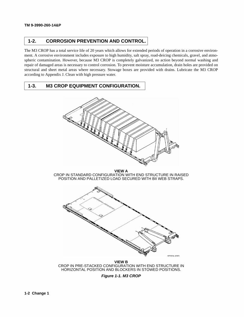
The M3 CROP has a total service life of 20 years which allows for extended periods of operation in a corrosive environ-ment. A corrosive environment includes exposure to high humidity, salt spray, road-deicing chemicals, gravel, and atmo-spheric contamination. However, because M3 CROP is completely galvanized, no action beyond normal washing andrepair of damaged areas is necessary to control corrosion. To prevent moisture accumulation, drain holes are provided onstructural and sheet metal areas where necessary. Stowage boxes are provided with drains. Lubricate the M3 CROPaccording to Appendix J. Clean with high pressure water.
VIEW A CROP IN STANDARD CONFIGURATION WITH END STRUCTURE IN RAISED
POSITION AND PALLETIZED LOAD SECURED WITH BII WEB STRAPS.
VIEW B CROP IN PRE-STACKED CONFIGURATION WITH END STRUCTURE IN
HORIZONTAL POSITION AND BLOCKERS IN STOWED POSITIONS.
Figure 1-1. M3 CROP
1-2. CORROSION PREVENTION AND CONTROL.
1-3. M3 CROP EQUIPMENT CONFIGURATION.

TM 9-3990-260-14&P
1-3
VIEW C SIX CROPS IN STACKED, RETROGRADE CONFIGURATION.
BOTTOM CROP HAS END STRUCTURE RAISED.
VIEW D SIX CROPs IN RETROGRADE CONFIGURATION.
POSITIONED IN AN ISO CONTAINER FOR SHIPMENT.
Figure 1-1. M3 CROP (Cont)

TM 9-3990-260-14&P
1-4 Change 1
Refer to paragraph 2-18 and paragraph 4-4 for storage or shipment instructions for the M3 CROP.
Refer to TM 750-244-6, Procedures for Destruction of Tank-automotive Equipment to Prevent Enemy Use (U.S. ArmyTank-automotive and Armaments Command).
Beware of payload movement during normal loading/unloading operations. Ensure web straps, blocker assemblies, andsideboard kit (if so equipped) are correctly installed. The M3 CROP should be loaded on truck or trailer using the LoadHandling System (LHS). M3 CROPs should be stacked using a forklift or other material handling equipment. Never walkunder an M3 CROP when it is being lifted, loaded or unloaded. The M3 CROP deck is not capable of holding a forklift. Donot drive a forklift on the deck while loading cargo; load from the side.
For information concerning the warranty, contact the U.S. Army Tank-automotive and Armaments Command, ATTN:AMSTA-LC-CHHE, Warren, MI 48397-5000 or telephone DSN 786-6967 or Area Code (586) 574-6967.
If your M3 CROP needs improvement, let us know. Send us an EIR. You, the user, are the only one who can tell us whatyou don’t like about your equipment. Let us know why you don’t like the design. Put it on an SF Form 368 (Product Qual-ity Deficiency Report). Mail it to us at: U.S. Army Tank-automotive and Armaments Command, ATTN: AMSTA-TR-E-PQDR, Warren, MI 48397-5000. We will send you a reply. For those with access to the World Wide Web (www), the EIRcan be submitted through the Army Electronic Product Support (AEPS) web site. The site is https://aeps.ria.army.mil.
If there are any Quality Assurance/Quality Control problems with the M3 CROP, put the problem on an SF Form 368(Product Quality Deficiency Report) and mail it to us at: U.S. Army Tank-automotive and Armaments Command,ATTN: AMSTA-TR-E-PQDR, Warren, MI 48397-5000. We will send you a reply. For those with access to the WorldWide Web (www), the QDR can be submitted through the Army Electronic Product Support (AEPS) web site. The site ishttps://aeps.ria.army.mil.
1-4. PREPARATION FOR STORAGE OR SHIPMENT.
1-5. DESTRUCTION OF ARMY MATERIAL TO PREVENT ENEMY USE.
1-6. SAFETY, CARE, AND HANDLING.
1-7 M3 CROP WARRANTY INFORMATION.
1-8. REPORTING EQUIPMENT IMPROVEMENT RECOMMENDATIONS (EIRs).
1-9. QUALITY ASSURANCE/QUALITY CONTROL (QA/QC).

TM 9-3990-260-14&P
Change 1 1-5
The following abbreviations are used extensively throughout this manual:
AAL Additional Authorization List BII Basic Issue Items BOI Basis of Issue CAGE Contractor and Government Entity COEI Components of End Item CROP Container Roll-In/Out PlatformHAE Hook Arm ExtensionHEMTT Heavy Expanded Mobility Tactical TruckISO International Standards Organization LHS Load Handling System NSN National Stock Number PLS Palletized Load System PLST Palletized Load System Trailer PMCS Preventive Maintenance Checks and Services SMR Source, Maintenance, and Recoverability S/N Serial NumberTIK Trailer Interface Kit TMDE Test, Measurement, and Diagnostic Equipment U/I Unit of Issue U/M Unit of Measure
1-10. LIST OF ABBREVIATIONS.

TM 9-3990-260-14&P
1-6 Change 1
Section II. EQUIPMENT DESCRIPTION
a. Equipment Characteristics. (1) The M3 CROP is a welded steel, galvanized, steel-floored, flat cargo body with a folding
front end structure assembly for stacking and front and rear blocker assemblies. The M3CROP is usually loaded and unloaded by the Load Handling System (LHS), but can alsobe moved by forklift or other material handling equipment capable of handling such loads.Do not drive a forklift on the M3 CROP deck; doing so exceeds the point load capability ofthe deck.
(2) A fully loaded M3 CROP can be inserted into an ISO container directly from a PLS truckor by using a forklift. M3 CROP has built-in shoring devices to secure it inside an ISO con-tainer. No additional shoring is required.
(3) M3 CROP has four twistlock aperture plates that allow each stacked M3 CROP to besecured by the M3 CROP directly beneath it. Up to six M3 CROPs can be stacked formovement on a PLS truck or trailer. A stack of six also fits into an ISO container. Whenstacking M3 CROPs, the lower unit upon which another is to be stacked must have itsremovable center blocker assembly and two rear blocker assemblies repositioned.
(4) Although M3 CROP twistlocks function similar to ISO twistlocks, M3 CROP twistlocksare not positioned for use as ISO securing mechanisms due to the smaller footprint of theM3 CROP when compared to a Flatrack.
(5) M3 CROPs can be shipped on railcars, on PLS trucks and trailers, HEMTT LHS and onISO compatible commercial trucks when in ISO containers.
(6) Each M3 CROP is provided with fourteen (14) web straps to allow transport of cargo.
b. Capabilities. (1) The M3 CROP can be loaded to and from the ground, a loading dock, an ISO container, or
PLS trailer using the PLS truck-mounted LHS. The M3 CROP will accommodate nominalloads of 32,450 lbs (14,719 kg) when loaded in an ISO container or on a PLS truck ortrailer.
(2) The M3 CROP is capable of being transported on C-130, C-141, C-5 and C-17 aircraftwhile secured to a 463L pallet train, while loaded to 36,250 lbs (16,443 kg) maximumgross weight.
(3) The M3 CROP is capable of being sling lifted by a CH-47D helicopter, utilizing a dualpoint lift, at a gross weight of 25,000 lbs (11,340 kg).
(4) M3 CROPs can be stacked 10 high on a flat surface. This is allowed for storage only. (5) Six empty M3 CROPs, five with the end structure assembly folded down, can be stacked
together and loaded in an ISO container, on the PLS trailer, and on the PLS truck using theLHS.
(6) M3 CROP can be moved by a forklift with forks that are a minimum of 68 in. (173 cm) inlength.
(7) M3 CROP can be carried on a HEMTT LHS (M1120, M1120A2, M1120A2R1). For spe-cific load requirements/restrictions, see HEMTT LHS TM 9-2320-304-14&P.
1-11. M3 CROP EQUIPMENT CHARACTERISTICS, CAPABILITIES, AND FEATURES.

TM 9-3990-260-14&P
Change 1 1-7
c. Features. (1) A welded, galvanized, steel frame with a hinged end structure assembly and removable
center and rear blocker assemblies. Capable of being stacked vertically and secured by theCROP directly beneath.
(2) Two enclosed, lockable stowage boxes in the rear deck area. (3) Hinged end structure assembly that lays flat on the deck for stacking. (4) Side tiedown D-rings (19 per side) of 10,000 lbs (4,536 kg) capacity to secure payloads. (5) Four multipurpose provision rings, Class 3, 25,000 lbs (11,340 kg), to permit sling lifting
by helicopter and tiedown while loaded to 36,250 lbs (16,443 kg) maximum gross weight,on rail cars and trailers. The multipurpose provision rings also accommodate tiedown ofvehicles.
(6) Forklift pockets to allow movement of loaded and unloaded M3 CROPs. (7) Bracing mechanisms to secure M3 CROP inside an ISO container. (8) Rollers at the rear of the M3 CROP. (9) Twistlocks at each corner of the M3 CROP for stacking. (10) Pins for securing end structure assembly in upright position and lowering of end structure
assembly to horizontal position.(11) On the M3 CROP (S/N SC09001 and up), the tools used for raising and lowering the end
structure are stored in special locations on the front of the platform for quick accessibilityand the Hook Arm Extension can be stored beneath the rear deck of the platform.

TM 9-3990-260-14&P
1-8
a. End Structure Assembly and Bail Bar. The bail bar (1) on the end structure assembly (2) ofthe M3 CROP is used as a lifting point for the M3 CROP. The bail bar (1) couples with the LHS hook arm to liftand pull the M3 CROP onto the PLS truck. The entire end structure assembly (2) can be lowered onto the M3CROP deck to prepare the M3 CROP for unloaded stacking. When stacked, the end structure assembly (2) fitsinside the rails (3) of the M3 CROP above it, thus allowing M3 CROPs to be stacked vertically.
b. Rails. The M3 CROP rails (3), located on the bottom of the M3 CROP, have dinlocks which matewith locking plates on the PLS truck and trailer to secure the M3 CROP for road and rail operations.
c. End Structure Assembly Hinge. Two tapered, threaded, front pins (4) with hex nuts, lockwashers, and two straight, threaded, rear pins (5) with hex nuts and lock washers are provided as an integral part ofthe end structure assembly (2). The pins (4 and 5) are used to secure the end structure assembly (2) in the uprightposition for normal use and allow the end structure assembly (2) to be folded in the horizontal position for stacking.
d. Bracing Mechanisms. Bracing mechanisms (6) used to brace the M3 CROP inside an ISO con-tainer are located at the two front corners. No further shoring is required to secure the M3 CROP inside an ISOcontainer.
1-12. M3 CROP LOCATION AND DESCRIPTION OF MAJOR COMPONENTS.

TM 9-3990-260-14&P
1-9
e. Twistlocks. Twistlocks (7) are located at each corner and allow six empty M3 CROPs to bestacked and locked together. Each M3 CROP is secured by the twistlocks (7) of the M3 CROP directly beneath it.
f. Stowage Boxes. Two large, lockable stowage boxes (8) are located in the deck toward the rearof the M3 CROP. The lids on the stowage boxes (8) are of the same material as the deck. The deck is not capable ofholding a forklift; the point load of the tires exceed the deck point load capability.
g. Rollers. Rollers (9) are located at the bottom rear of the M3 CROP. Rollers (9) are used for load-ing/unloading M3 CROP onto the PLS truck and trailer, and into and out of an ISO container. Rollers (9) can bereplaced if damaged.
h. Tiedown Rings. A total of 38 10,000 lbs (4,536 kg) capacity tiedown rings (10) are provided (19on each side) to secure payloads or to secure M3 CROP for modes of shipping other than stacked in an ISO con-tainer, or on a PLS truck or trailer. Additionally, four 25,000 lbs (11,340 kg) capacity multipurpose provision rings(11) are provided (two on each end) for sling lifting and securing on railcars.
i. Blocker Assemblies. The M3 CROP has five blocker assemblies. The left and right frontblocker assemblies (12) are welded in place and cannot be removed. The center blocker (13) and two rear blockerassemblies (14) must be positioned to the stowed location to allow M3 CROPs to be stacked.

TM 9-3990-260-14&P
1-10 Change 1
j. End Structure Assembly and Bail Bar. The bail bar (1) on the end structure assembly (2) ofthe M3 CROP (S/N SC09001 and up) is used as a lifting point for the M3 CROP (S/N SC09001 and up). The bail bar(1) couples with the LHS hook arm to lift and pull the M3 CROP (S/N SC09001 and up) onto the PLS truck. Theentire end structure assembly (2) can be lowered onto the M3 CROP (S/N SC09001 and up) deck to prepare the M3CROP (S/N SC09001 and up) for unloaded stacking. When stacked, the end structure assembly (2) fits inside therails (3) of the M3 CROP (S/N SC09001 and up) above it, thus allowing M3 CROPs (S/N SC09001 and up) to bestacked vertically. The top of the end structure assembly (2) of the M3 CROP (S/N SC09001 and up) has been mod-ified for storing the two Trailer Interface Kit ramps.
k. Rails. The M3 CROP (S/N SC09001 and up) rails (3), located on the bottom of the M3 CROP(S/N SC09001 and up), have dinlocks which mate with locking plates on the PLS truck and trailer to secure the M3CROP (S/N SC09001 and up) for road and rail operations.
l. End Structure Assembly Hinge. Two tapered, threaded, front pins (4) with hex nuts, lockwashers, and two straight, threaded, rear pins (5) with hex nuts and lock washers are provided as an integral part ofthe end structure assembly (2). The pins (4 and 5) are used to secure the end structure assembly (2) in the uprightposition for normal use and allow the end structure assembly (2) to be folded in the horizontal position for stacking.
m. Bracing Mechanisms. Bracing mechanisms (6) used to brace the M3 CROP (S/N SC09001and up) inside an ISO container are located at the two front corners. No further shoring is required to secure the M3CROP (S/N SC09001 and up) inside an ISO container.
451
36
2
8
7

TM 9-3990-260-14&P
Change 1 1-10.1
n. Handling Tools Storage. A hinged door box (7) has been added to the front, left-handblocker assembly on the M3 CROP (S/N SC09001 and up) as an integral storage area for the pin tightening rod, ham-mer and socket wrench. Between the legs of the end structure assembly (2) a post (8) has been mounted for storage ofthe 2-1/4 inch socket on the M3 CROP (S/N SC09001 and up).
o. Twistlocks. Twistlocks (9) are located at each corner and allow six empty M3 CROPs (S/NSC09001 and up) to be stacked and locked together. Each M3 CROP (S/N SC09001 and up) is secured by the twist-locks (9) of the M3 CROP (S/N SC09001 and up) directly beneath it.
p. Stowage Boxes. Two large, lockable stowage boxes (10) are located in the deck toward therear of the M3 CROP (S/N SC09001 and up). The lids on the stowage boxes (10) are of the same material as thedeck. The deck is not capable of holding a forklift; the point load of the tires exceed the deck point load capability.
q. Rollers. Rollers (11) are located at the bottom rear of the M3 CROP (S/N SC09001 and up).Rollers (11) are used for loading/unloading M3 CROP (S/N SC09001 and up) onto the PLS truck and trailer, and intoand out of an ISO container. Rollers (11) can be replaced if damaged.
r. Tiedown Rings. A total of 38 10,000 lbs (4,536 kg) capacity tiedown rings (12) are provided(19 on each side) to secure payloads or to secure M3 CROP (S/N SC09001 and up) for modes of shipping other thanstacked in an ISO container, or on a PLS truck or trailer. Additionally, four 25,000 lbs (11,340 kg) capacity multi-purpose provision rings (13) are provided (two on each end) for sling lifting and securing on railcars.
s. Blocker Assemblies. The M3 CROP (S/N SC09001 and up) has five blocker assemblies.The left and right front blocker assemblies (14) are welded in place and cannot be removed. The center blocker (15)and two rear blocker assemblies (16) must be positioned to the stowed location to allow M3 CROPs (S/N SC09001and up) to be stacked.
t. Hook Arm Extension Storage. The M3 CROP (S/N SC09001 and up) has a rear storagearea (17) underneath the main decking that allows for storage of the Hook Arm Extension.
11
17
13
12
1610
14
9
15

TM 9-3990-260-14&P
1-10.2 Change 1
Table 1-1 contains the equipment data that applies to the M3 CROP.
Table 1-1. Equipment Data
Section III. PRINCIPLES OF OPERATION
The M3 CROP is equipped with an end structure assembly capable of being pinned in the upright position for normal oper-ation and placed horizontally for stacking. All components are permanently attached to the M3 CROP with the exceptionof BII, center and rear blocker assemblies, end structure assembly, twistlocks, rollers, stowage box doors, and bracingmechanisms. Refer to TM 9-2320-364-10 for PLS flatrack loading/unloading procedures.
BII are stored in the stowage boxes located in the cargo deck. Prior to stacking, the blocker assemblies must be removedfrom their normal positions and secured in their stowed positions. The center blocker assembly is removed from its normalposition just rear of the end structure assembly and secured longitudinally on either side of the cargo deck approximately18 inches (46 cm) from the front of the M3 CROP. The rear blocker assemblies are removed from their normal positions atthe rear of the cargo deck and secured longitudinally, each on its respective side of the cargo deck approximately 30 inches(76 cm) from the rear of the M3 CROP. The end structure assembly is normally in the upright position, but is positionedhorizontally on the deck for stacking. The twistlocks, rollers, stowage box doors, and bracing mechanisms remain attachedexcept for maintenance and replacement.
1-13. M3 CROP EQUIPMENT DATA.
Item Specification
Width: 91.00 in. (231.14 cm)
Height:(Ground to Deck)
10.11 in. (25.68 cm)
(Ground to top of End Structure Assembly bail barwhen laid flat on M3 CROP deck)
17.84 in. (45.31 cm)
(Ground to top of End Structure Assembly when inraised position, not to top of marker spring on M3CROP)
(Ground to top of End Structure Assembly when inraised position, with TIK Ramps installed on M3CROP S/N SC09001 and up)
62.90 in. (159.77 cm)
73.875 in. (187.64 cm)
(Ground to top of End Structure Assembly when inraised position, top of marker spring)
71.50 in. (181.61 cm)
Length: 233.27 in. (592.51 cm)
Weight (M3 CROP):
Weight (M3 CROP S/N SC09001 and up):
3,800 lbs (1,724 kg)
3,730 lbs (1,692 kg)
1-14. M3 CROP NORMAL OPERATION.

TM 9-3990-260-14&P
CHAPTER 2
OPERATING INSTRUCTIONS (M3 CROP)
Para Contents Page
2-1 Operator's PMCS Procedures .............................................................................................. 2-1 2-2 PMCS Warnings and Cautions............................................................................................. 2-1 2-3 Explanation of PMCS Table Entries ................................................................................... 2-2 2-4 Routing Diagram ................................................................................................................. 2-2 2-5 Interval Groupings .............................................................................................................. 2-2 2-6 M3CROP Lubrication Instructions ..................................................................................... 2-2 2-7 Shortened Intervals .............................................................................................................. 2-2 2-8 M3CROP Assembly and Preparation for Use ..................................................................... 2-11 2-9 Unlock and Lock M3CROP Twistlocks .............................................................................. 2-11 2-10 Installing/Stowing M3 CROP Center and Rear Blocker Assemblies .................................. 2-12 2-11 M3 CROP End Structure Assembly (A-Frame) Raising and Lowering Procedures ........... 2-18 2-12 Nuclear, Biological, and Chemical (NBC) Decontamination Procedures ........................... 2-22 2-13 Loading Single M3 CROP On PLS Truck or Trailer .......................................................... 2-22 2-14 Stacking/Loading and Unstacking/Unloading M3 CROP On PLS Truck, Stacking/Loading ................................................................................................................ 2-22 2-14 Stacking/Loading and Unstacking/Unloading M3 CROP On PLS Truck, Unstacking/Unloading ......................................................................................................... 2-27 2-15 Stacking/Loading M3 CROP On PLS Trailer ..................................................................... 2-30 2-16 Loading/Unloading ISO Container With M3 CROP From PLS Truck, Loading ................ 2-31 2-16 Loading/Unloading ISO Container With M3 CROP From PLS Truck, Unloading. ........... 2-38 2-17 Loading/Unloading ISO Container With M3 CROP Using Forklift, Loading. ................... 2-42 2-17 Loading/Unloading ISO Container With M3 CROP Using Forklift, Unloading. ............... 2-47 2-18 Preparation for Storage or Shipment ................................................................................... 2-51 2-19 M3 CROP Decals and Instruction Plates ............................................................................ 2-52
Section I. OPERATOR'S PREVENTIVE MAINTENANCE CHECKS AND SERVICES (PMCS)
2-1. OPERATOR'S PMCS PROCEDURES.
Table 2-1 (PMCS Table) has been provided so you can keep your equipment in good operating condition and ready for its primary mission.
2-2. PMCS WARNINGS AND CAUTIONS.
Always observe the Warnings and Cautions appearing in your PMCS Table. Warnings and Cautions appear before applicable procedures. You must observe these Warnings and Cautions to prevent serious injury to yourself and others, or to prevent your equipment from being damaged.
2-1

TM 9-3990-260-14&P
2-3. EXPLANATION OF PMCS TABLE ENTRIES.
a. Item Number Column. Item numbers appear in the order checks and services must be done for the interval listed. Numbers in this column are also for reference. When completing DA Form 2404 (Equipment Inspection and Maintenance Worksheet), include the item number for the check/service indicating a fault.
b. Interval Column. This column tells you when you must perform the procedure in the procedure column.
Perform the "Before" CHECKS prior to using the equipment. Perform the "During" CHECKS during the time you are using the equipment. Perform the "After" CHECKS after you have used the equipment.
c. Location Check/Service Column. This column provides the location and the item to be checked or serviced.
d. Procedure Column. This column gives the procedure you must perform to check or service the item listed in the Check/Service column to know if the equipment is ready or available for its intended mission or for operation. You must perform the procedure at the time stated in the interval column.
e. Not Fully Mission Capable If: Column. Information in this column tells you what faults will keep your equipment from being capable of performing its primary mission. If you experience check and service procedures that show faults listed in this column, do not operate the equipment. Follow standard operating proce- dures for maintaining the M3 CROP or reporting equipment failure.
f. Other Table Entries. Be sure to observe all special information and notes that appear in your table.
2-4. ROUTING DIAGRAM.
Figure 2-1 is a routing diagram showing the path to use around the M3 CROP during PMCS. Perform PMCS in the same order and following the same route each time.
2-5. INTERVAL GROUPINGS.
Operator PMCS intervals for the M3 CROP are as indicated in Table 2-1 and paragraph 2-3b above.
2-6. M3 CROP LUBRICATION INSTRUCTIONS.
Lubrication of the CROP is the responsibility of the operator/crew. Refer to Appendix J for lubrication instructions pertaining to the CROP.
2-7. SHORTENED INTERVALS.
Lubrication intervals are based on normal operation. Change the interval if lubricants are contaminated or if oper- ating the CROP under adverse operating conditions. Lubrication intervals for the CROP at Appendix J are based on time.
2-2

TM 9-3990-260-14&P
s-ch2-00 Figure 2-1. PMCS Walk-Around
Table 2-1. Operator's Preventive Maintenance Checks and Services
Item No.
Interval
Location Item to Check/Service
Procedure
Not Fully Mission Capable If:
1 Before End Structure Assembly Pins
Ensure front pins (1) and rear pins (2) are installed and secure in end struc-ture assembly.
Parts are missing or damaged.
2-3

TM 9-3990-260-14&P
Table 2-1. Operators Preventive Maintenance Checks and Services - Continued Item No.
Interval
Location Item to Check/Service
Procedure
Not Fully Mission Capable If:
2 Before Web Straps a. Before loading a CROP, check quantity and condition/operability of web straps (3). Fourteen web straps are located in the stowage boxes.
b. Ensure ratchet assembly (4) oper- ates properly.
c. Ensure hooks (5) are available and not broken, bent, or cracked.
a. So many cargo web straps are missing, dam- aged, broken, bent, frayed, or inoperable that there is not sufficient quantity for mission.
b. Ratchet is inopera- ble.
c. Hook is broken, bent or cracked.
3 Before Bumpers Ensure both bumpers (6) are available and serviceable for container insertion.
Either bumper is missing or damaged beyond use.
2-4
TM 9-3990-260-14&P
Change 1 2-4.1/(2-4.2 blank)
Table 2-1. Operator’s Preventive Maintenance Checks and Services - Continued
Item No. Interval
LocationItem toCheck/Service Procedure Not Fully Mission
Capable If:
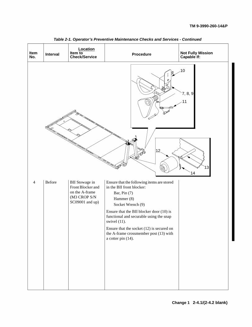
4 Before BII Stowage in Front Blocker and on the A-frame (M3 CROP S/N SC09001 and up)
Ensure that the following items are stored in the BII front blocker:
Bar, Pin (7)Hammer (8)Socket Wrench (9)
Ensure that the BII blocker door (10) is functional and securable using the snap swivel (11).
Ensure that the socket (12) is secured on the A-frame crossmember post (13) with a cotter pin (14).
13
7, 8, 9
14
12
11
10


TM 9-3990-260-14&P
Change 1 2-5
Table 2-1. Operators Preventive Maintenance Checks and Services - Continued
Item No. Interval
LocationItem toCheck/Service Procedure Not Fully Mission
Capable If:
5 During Web Straps Shortly after starting a mission and after driving over rough terrain, stop driving, get out and ensure cargo web straps (3) are not damaged and the cargo has not shifted. Tighten web straps if required.
Cargo web straps are damaged and allow cargo to move. Insufficient web straps to complete the mission.

TM 9-3990-260-14&P
2-6 Change 1
Table 2-1. Operators Preventive Maintenance Checks and Services - Continued
Item No. Interval
LocationItem toCheck/Service Procedure Not Fully Mission
Capable If:
6 After Blocker Assemblies
a. Visually inspect center blocker assembly mounting and stowage pockets (15) and both rear blocker assemblies mounting and stowage pockets (16 & 17) for corrosion, dirt, and damage.b. Visually inspect center blocker assembly (18) and both rear blocker assemblies (19 & 20) to ensure each is straight and free of bends, tears, or rips that would prevent its installation or installation of dunnage.
One or more blocker assembly is missing or damaged such that it cannot be installed or used properly.

TM 9-3990-260-14&P
Change 1 2-7
Table 2-1. Operators Preventive Maintenance Checks and Services - Continued
Item No. Interval
LocationItem toCheck/Service Procedure Not Fully Mission
Capable If:
7 After Twistlocks Rotate locking handle (21) completely in either direction. Push handle (21) up and rotate completely from stowed position to locked position. Inspect twistlock (22) for damage or corrosion. Rotate and pull down handle (21) to stowed position. Visually inspect for corrosion, dirt, and damage. Clean as required.
Twistlock will not rotate, cannot be pushed up to the locked position from the stowed position, or is otherwise damaged so it cannot be properly engaged and disengaged.

TM 9-3990-260-14&P
2-8 Change 1
Table 2-1. Operators Preventive Maintenance Checks and Services - Continued
Item No. Interval
LocationItem toCheck/Service Procedure Not Fully Mission
Capable If:
NOTE CROP must be loaded on PLS truck prior to performing Item No. (8).
8 After Rollers Ensure each roller (23) will rotate. Ensure each roller is not defaced or so out of round it will not roll properly.
Either roller is so worn, split, or defaced that proper loading to traileror into ISO container isnot possible.
Bail bar may have metal slivers or sharp edges. Wear gloves if handling or injury to per-sonnel could result.
9 After Bail Bar Check bail bar (24) for cracks or bent bar. Bail bar has cracks or is bent.

TM 9-3990-260-14&P
Change 1 2-9
Table 2-1. Operators Preventive Maintenance Checks and Services - Continued
Item No. Interval
LocationItem toCheck/Service Procedure Not Fully Mission
Capable If:
10 After Stowage Boxes Ensure doors (25) or fasteners (26) are not damaged.
Door cannot be closed.
11 After Tiedown Rings and Multipurpose Provision Rings
Ensure all multipurpose provision rings (27), tiedown rings (28), and tiedown ring cross bars (29) are serviceable and not damaged or distorted to the point that they can no longer be used for their primary purpose.
If more than four tiedown rings or cross bars on the same side are non-operational or if one multipurpose provision ring is non-operational.
12 After Deck a. Ensure deck is not ripped or torn. a. Deck is ripped or torn so road is visiblethrough the damage.
b. Ensure rivets are not missing. b. Two or more consecutive rivets or more than 10 rivets total are missing.

TM 9-3990-260-14&P
2-10 Change 1
Table 2-1. Operators Preventive Maintenance Checks and Services - Continued
Item No. Interval
LocationItem toCheck/Service Procedure Not Fully Mission
Capable If:
13 After Bracing Mechanisms
Ensure threaded rod (30) is not bent and threads are serviceable. Adjusting collar can be adjusted entire length of threaded rod (30). Ensure cam (31) can be freely rotated around threaded rod (30) and is not bent. Ensure adjusting and securing pin (32) and hitch pin clip (33) are available and serviceable.
Either of the two bracing mechanism threaded rods cannot be adjusted, either cam will not rotate to be inserted into a shoring slot in an ISO container, or any threaded rod or hitch pin clip is missing.
TM 9-3990-260-14&P
Section II. OPERATION UNDER USUAL CONDITIONS
2-8. M3 CROP ASSEMBLY AND PREPARATION FOR USE.
a. Unpacking. Refer to Para 4-4, Unpacking and Packing, for unpacking instructions.
b. Assembly and Installation. The CROP is delivered fully assembled.
2-9. UNLOCK AND LOCK M3 CROP TWISTLOCKS.
Procedures for unlocking and locking twistlocks are covered in stacking and unstacking procedures, paragraph 2-14. the twistlocks are used to secure stacked CROPs. They are not ISO compatible.
2-11

TM 9-3990-260-14&P
2-10. INSTALLING/STOWING M3 CROP CENTER AND REAR BLOCKER ASSEMBLIES.
a. Installing the Center Blocker Assembly.
NOTE
End structure assembly must be in the raised position to install the center blocker assembly.
(1) Disconnect two bolt snaps (1) from their positions clipped to the closest tiedown ring (2) and remove the center blocker (3) from its stowed position.
(2) Insert the center blocker assembly legs (4) into the two circular holes located at the front edge of the deck, on both sides of the end structure assembly (5).
(3) Secure the center blocker assembly (3) in the normal position by clipping each bolt snap (1)
to the spring snap lanyard (6) which is looped through a small hole in the front of the main beam.
2-12

TM 9-3990-260-14&P
b. Stowing the Center Blocker Assembly.
(1) Disconnect two bolt snaps (1) from their positions clipped to each spring snap lanyard loop (6), remove the center blocker (3), and place it at its stowed position.
(2) Insert the center blocker assembly legs (4) into the circular holes in the side beams located at either side of the CROP, ensuring no part of the center blocker assembly protrudes past the
outside edge of the CROP side beam.
(3) Secure the center blocker assembly (3) by inserting each bolt snap (1) through the closest tiedown ring (2) secure the bolt snap (1) to its own lanyard.
2-13

TM 9-3990-260-14&P
2-10. INSTALLING/STOWING M3 CROP CENTER AND REAR BLOCKER ASSEMBLIES (CONT).
c. Installing the Rear Blocker Assemblies.
NOTE
• The rear blockers are interchangeable. • The smooth side of the blocker must face the cargo deck in the operational
position. • The hitch pin clip and lanyard must be positioned on the side of the blocker
facing away from the deck when in the operational position. • The following procedures are applicable for either rear blocker.
(1) Disconnect the two hitch pin clips (7) which are clipped to the closest tiedown ring (2) and remove the rear blocker (8) from its stowed position.
2-14

TM 9-3990-260-14&P
(2) Insert the rear blocker assembly legs into the circular holes (9) located at the rear edge of the deck. Ensure the smooth side (sheet metal side) is facing the cargo deck.
(3) Ensure the lanyards (6) and hitch pin clips (7) are positioned on the side of the blocker facing away from the cargo deck.
(4) Insert the hitch pin clips (7) through the holes in the bottoms of the blocker legs (10) where they protrude through and below the rear beam.
2-15

TM 9-3990-260-14&P
2-10. INSTALLING/STOWING M3 CROP CENTER AND REAR BLOCKER ASSEMBLES (CONT).
d. Stowing the Rear Blocker Assemblies.
NOTE
• The rear blockers are interchangeable.
• The smooth side of the blocker must face away from the cargo deck in the stowed position.
• The hitch pin clip and lanyard must be positioned on the side of the blocker facing the deck when in the stowed position.
• The following procedures are applicable for either rear blocker.
(1) Disconnect two hitch pin clips (7) from their normal positions inserted through the hole in the bottom of the blocker legs (10) and remove the rear blocker from its normal position.
2-16

TM 9-3990-260-14&P
NOTE
•• The left rear blocker is stowed on the left side of the CROP deck and the right rear blocker is stowed on the right side of the CROP deck.
•• Ensure that the smooth side (sheet metal side) of the blockers is facing away from the cargo deck in the stowed position.
•• The forward leg of the blocker is inserted into the circular hole in the side beam, located approximately 71 inches (180 cm) from the rear edge of the deck.
(2) Insert the rear blocker assembly legs (11) into the circular holes (9) located at the side of the deck. Ensure the smooth side (sheet metal side) is facing away from the cargo deck.
(3) Ensure the hitch pin clips (7) and lanyards are positioned on the side of the blocker facing the cargo deck.
(4) Clip each hitch pin clip (7) to the nearest tiedown ring (2).
2-17
TM 9-3990-260-14&P
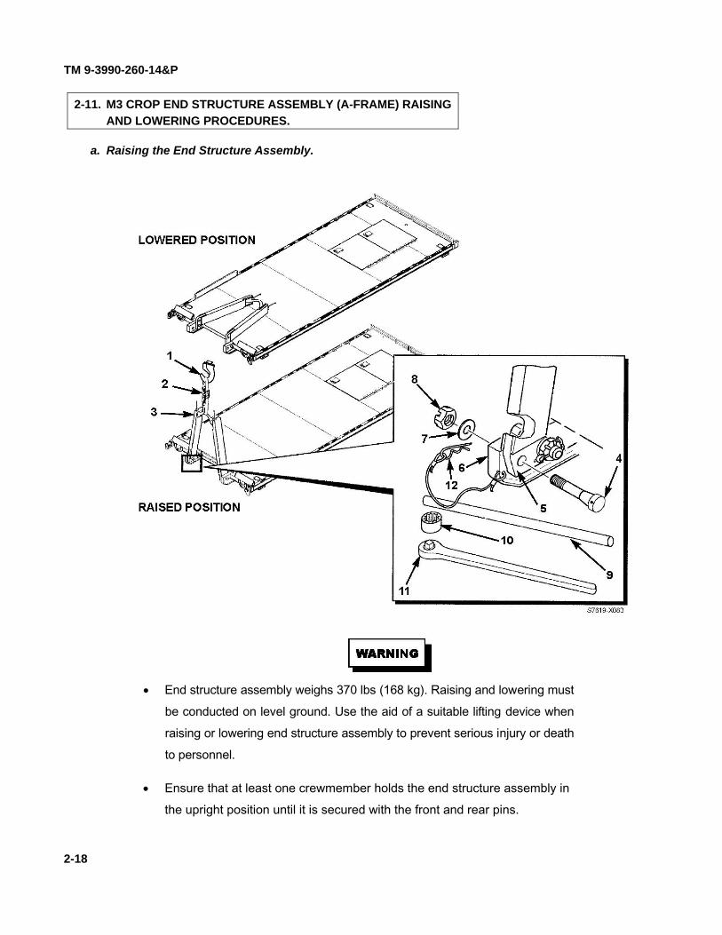
2-11. M3 CROP END STRUCTURE ASSEMBLY (A-FRAME) RAISING AND LOWERING PROCEDURES.
a. Raising the End Structure Assembly.
• End structure assembly weighs 370 lbs (168 kg). Raising and lowering must be conducted on level ground. Use the aid of a suitable lifting device when raising or lowering end structure assembly to prevent serious injury or death to personnel.
• Ensure that at least one crewmember holds the end structure assembly in the upright position until it is secured with the front and rear pins.
2-18

TM 9-3990-260-14&P
Change 1 2-19
CAUTION
Do not drive a forklift on the CROP deck. Failure to comply will exceed point load capa-bility of the deck and damage the deck.
NOTE Raising and lowering the end structure assembly requires two crewmembers.
(1) Remove the following items from the CROP stowage boxes or from the front storage areason the M3 CROP (S/N SC09001 and up).
2-1/4 inch Socket (10) Socket Wrench (11) Pin Tightening Rod (9)
(2) Remove the following items from CROP stowage box. Two Front Pins (4) Lock Washers (7) Castle Nuts (8) Hitch Pin Clips (12) Web Straps (2)
NOTE Ensure front pins and holes in end structure assembly are clean and free of dirt or othercontamination.
(3) Using a suitable lifting device (1) and web strap (2), raise end structure assembly (3) to itsupright position.
(4) With the aid of an assistant holding the end structure assembly (3) to ensure holes arealigned, install two front pins (4) through end structure assembly pin support plate (5) andthrough pin blocks (6). Secure with lock washers (7) and castle nuts (8).
NOTE Do not use pin tightening rod to turn front and rear pins. Use socket and wrench to tightencastle nuts.
(5) While holding front pins (4) with pin tightening rod (9), alternately tighten left and rightfront pin castle nuts (8) using 2-1/4 inch socket (10) and socket wrench (11). Ensure thesplit in each lock washer is compressed and the nuts are firmly tightened using full armstrength only. Do not over tighten by standing on the socket wrench, using your feet topush against the socket wrench, or using other leverage gaining means such as a “cheaterbar or pipe.”
NOTE A tether is no longer used to secure hitch pin clips on later model CROPs.
(6) Install hitch pin clips (12) in both front pins (4). (7) Return the following items to CROP stowage boxes or into the front storage areas on the
M3 CROP (S/N SC09001 and up). Pin Tightening Rod (9) Socket Wrench (11)2-1/4 inch Socket (10)
(8) Return web strap (2) to CROP storage box.

TM 9-3990-260-14&P
2-20
b. Lowering the End Structure Assembly.
2-11. M3 CROP END STRUCTURE ASSEMBLY (A-FRAME) RAISING AND LOWERING PROCEDURES (CONT).

TM 9-3990-260-14&P
Change 1 2-21
• End structure assembly weighs 370 lbs (168 kg). Raising and lowering must be con-ducted on level ground. Use the aid of a suitable lifting device when raising or lower-ing end structure assembly to prevent serious injury or death to personnel.
• Ensure at least one crewmember physically holds the end structure assembly in theupright position during procedures to remove two front pins. Failure to comply mayresult in severe injury or death to personnel.
(1) Remove center blocker assembly (14) and secure it at its stowed position. (2) Remove the following items from the CROP stowage boxes or from the front storage areas
on the M3 CROP (S/N SC09001 and up).Pin Tightening Rod (9) Socket Wrench (11)2-1/4 inch Socket (10) Hammer (13)
NOTEA tether is no longer used to secure hitch pin clips on later model CROPs.
(3) Remove the two hitch pin clips (12) from two front pins (4). (4) With the aid of an assistant holding the end structure assembly (3) in the upright position,
remove two front pins (4), lock washers (7), and castle nuts (8) using pin tightening rod(9), 2-1/4 inch socket (10), and socket wrench (11). Use hammer (13) to loosen front pinsfor removal, if required.
NOTE The following procedure may first require pushing the end structure assembly from its verticalposition, toward the deck, until it loosens the rear pins enough to be lowered. If the endstructure assembly cannot be pushed over, loosen the hex nuts on the two rear pinsapproximately 1/4 turn and try again to push the end structure assembly over toward the deck.
(5) With the aid of an assistant, lower the end structure assembly (3) to the cargo deck.
NOTEA tether is no longer used to secure hitch pin clips on later model CROPs.
(6) Replace lock washers (7), castle nuts (8), and hitch pin clips (12) on the front pins (4). (7) Return the following items to the CROP stowage boxes or into the front storage areas on
the M3 CROP (S/N SC09001 and up).Pin Tightening Rod (9) 2-1/4 inch Socket (10) Socket Wrench (11) Hammer (13)
(8) Return the following items to CROP storage box. Two Front Pins (4) Lock Washers (7) Castle Nuts (8) Hitch Pin Clips (12)

TM 9-3990-260-14&P
2-22
Refer to FM 3-11.5, Chemical, Biological, and Radiological Decontamination, for CBR instructions.
For loading and transporting a single loaded or unloaded CROP on truck or trailer, the end structure assembly must besecured in the raised position. Refer to TM 9-2320-364-10 for procedures to load and unload the CROP to truck or trailerusing the Load Handling System (LHS).
a. Stacking/Loading.
• CROPs must be empty when stacked. Attempting to stack loaded CROPs could causeserious injury or death to personnel.
• Always lift a stack of CROPs by connecting to the bottom CROP, either by overheadMHE or forklift. Failure to comply may result in severe injury to personnel or dam-age to equipment.
CAUTION
• Personnel are cautioned that a tripping hazard exists around the CROP. Failure to takeheed of this caution could result in minor injury to personnel.
• Ensure center and rear blocker assemblies are secured in their stowed positions priorto stacking.
• Ensure all tiedown rings are in their lowest position prior to stacking.
NOTE• Six CROPs loaded on PLS truck is maximum if legal height requirement must be met.
• CROPs may be stacked either on the ground or on the truck.
• The LHS can load PLS truck or trailer with CROP stacked with 5 more CROPs.
• There must be at least one empty CROP loaded on the truck using the PLS.
• Two people are required for stacking/loading CROPs.
• The top CROP of a stack of CROPs must have the end structure assembly securedusing one web strap fastened to the first tiedown ring on one side and the sixthtiedown ring on the other side of the CROP.
2-12. NUCLEAR, BIOLOGICAL, AND CHEMICAL (NBC) DECONTAMINATION PROCEDURES.
2-13. LOADING SINGLE M3 CROP ON PLS TRUCK OR TRAILER.
2-14. STACKING/LOADING M3 CROP ON PLS TRUCK.

TM 9-3990-260-14&P
Change 1 2-23
(1) For each CROP upon which another is being stacked (bottom CROP), ensure all remov-able blockers (1) are secured in their stowed positions (6) at the sides of the deck.
(2) For the CROP upon which another is being stacked (bottom CROP), push up and turn han-dle (3) on all four corner twistlocks (2) to the UNLOCKED position. The twistlocks raisedto the UNLOCKED position act as guides for CROP being stacked (top CROP).
(3) For the CROP upon which another is being stacked (bottom CROP), ensure the tiedownring immediately adjacent to each of the four twistlocks is in its lowest position, not pro-truding above the deck.
(4) Remove three web straps (4) from CROP stowage boxes (5) located in the deck of the lastCROP to be stacked (the one which will end up on top).
• Ensure web straps are wrapped a minimum of three times around ratchet of web strap.Failure to comply may result in web strap being released and CROP may fall, causingsevere injury or death to personnel.
• One M3 CROP weighs 3,800 lbs (1,724 kg) and the M3 CROP (S/N SC09001 and up)weighs 3,730 lbs (1,692 kg). Six M3 CROPs weigh 22,800 lbs (10,342 kg) and six M3CROPs (S/N SC09001 and up) weigh 22,380 lbs (10,152 kg). Gross weight of a fullyloaded CROP is 36,250 lbs (16,443 kg). Ensure all personnel stand clear of CROPswhen being moved. Failure to comply may result in severe injury or death to personnel.
• Always lift a stack of CROPs by connecting to the bottom CROP. Failure to complymay result in severe injury to personnel or damage to equipment.

TM 9-3990-260-14&P
2-24
(5) On each CROP to be stacked, ensure end structure assembly (7) is in the horizontal positionand that all removable blockers (1) are removed and set aside during the stacking procedure.
(6) Attach one web strap (4) from left to right, to two front tiedown rings (D-rings) (8), eachlocated third tiedown ring from the front of the CROP.
(7) Attach a second web strap (9) from left to right, to two rear tiedown rings (D-rings) (8), eachlocated third tiedown ring from the rear of the CROP.
(8) Attach a third web strap (10) to tiedown ring (8) at rear of CROP.
2-14. STACKING/LOADING M3 CROP ON PLS TRUCK (CONT).

TM 9-3990-260-14&P
Change 1 2-25
Ensure pads on web straps are positioned in lifting clevis of lifting device. Failure to com-ply may result in breakage of web straps causing severe injury or death to personnel.
(9) Attach two web straps (4 & 9) to hook of lifting device (11).
The M3 CROP weighs 3,800 lbs (1,724 kg) and the M3 CROP (S/N SC09001 and up)weighs 3,730 lbs (1,692 kg). Ensure all personnel stand clear of CROP when CROP is be-ing moved. Failure to comply may result in severe injury or death to personnel.
CAUTION
Ensure lifting device is positioned directly over center of CROP prior to lifting CROP offground. Failure to comply may result in uneven lifting of CROP and damage to equipment mayresult. Ensure strap is not hanging down during lifting.
(10) With the aid of an assistant holding web strap (10), raise CROP until CROP clears ground.Ensure CROP is level.
NOTE If CROP is not being raised level, perform Steps (11) through (13). If CROP is level, go on toStep (14).
(11) If CROP is not level, lower CROP to ground. (12) Shorten or lengthen two web straps (4 & 9) as required. (13) Repeat Steps (9) through (11) until CROP is level when raised.
CAUTION
Ensure CROP twistlocks are free of snow, dirt, and debris prior to lowering CROP beingstacked or proper locking will not occur.
NOTE The twistlocks in the UNLOCKED position will guide the CROP to the correct position to lockthe twistlocks of the bottom CROP.
(14) Using the lifting device (11) and assistant, position and lower CROP onto CROP with endstructure assembly in vertical (raised) position or onto CROP on top of stack.

TM 9-3990-260-14&P
2-26
(15) Turn handle (3) on all four twistlocks (2) (bottom CROP) until stacked CROP (top CROP) islocked in place.
(16) Remove three web straps (4, 9, & 10) from lifting device (11) and tiedown rings (8). (17) Install previously removed blockers (1) to the stowed positions. (18) Repeat steps (2) through (16) for additional CROPs being stacked. Each CROP is locked in
place using twistlocks of the CROP below it. (19) For the last CROP stacked (the top CROP), secure the end structure assembly by fastening
one end of a web strap to the first tiedown ring on one side of the CROP and the other end ofthe web strap to the sixth tiedown ring on the other side of the CROP. Tighten the web strap.
(20) If stack of CROPs is to be inserted in an ISO container locally with no further transport byPLS truck or trailer required, stow two web straps in CROP stowage boxes (5) located indeck of CROP on top.
(21) If stack of CROPs is to be transported any way other than in an ISO container (PLS truck/trailer, air, railcar, helicopter), remove sufficient web straps from the stowage boxes to securestack of CROPs. Use two web straps per stacked CROP, evenly spaced, fastened to thetiedown rings of the bottom CROP and stretched across the top of the stack of CROPs. Usetwo web straps for one CROP, four web straps for two CROPs, six straps for three CROPS,eight web straps for four CROPs, and 10 web straps for the maximum of five CROPs stackedon the sixth and bottom CROP.
2-14. STACKING/LOADING M3 CROP ON PLS TRUCK (CONT).

TM 9-3990-260-14&P
2-27
b. Unstacking/Unloading. (1) Using the LHS, remove stack of CROPs from truck. Refer to TM 9-2320-364-10 for proce-
dure to unload the CROP from truck from trailer using the Load Handling System (LHS).
(2) Remove three removable blockers (1) from CROP to be unstacked (top CROP) and set themaside.
(3) Remove two web straps (12) from CROP stowage boxes (5) located in the deck of CROPstacked on top, or remove all web straps securing the stack of CROPs, if used.
(4) Remove the web strap securing the end structure assembly on the CROP stacked on top.

TM 9-3990-260-14&P
2-28 Change 1
• Ensure web straps are wrapped a minimum of three times around ratchet of web strap.Failure to comply may result in web strap being released and M3 CROP may fall,causing severe injury or death to personnel.
• One M3 CROP weighs 3,800 lbs (1,724 kg) and the M3 CROP (S/N SC09001and up) weighs 3,730 lbs (1,692 kg). Six M3 CROPs weigh 22,800 lbs (10,342 kg)and six M3 CROPs (S/N SC09001 and up) weigh 22,380 lbs (10,152 kg). Grossweight of a fully loaded CROP is 36,250 lbs (16,443 kg). Ensure all personnel standclear of M3 CROP when M3 CROP is being moved. Failure to comply may result insevere injury or death to personnel.
• Always lift a stack of M3 CROPs by connecting to the bottom M3 CROP. Failure tocomply may result in severe injury to personnel or damage to equipment.
(5) Attach one web strap (4) from left to right, to two front tiedown rings (D-rings) (8), eachlocated third tiedown ring from the front of the CROP.
(6) Attach a second web strap (9) from left to right, to two rear tiedown rings (D-rings) (8),each located third tiedown ring from the rear of the CROP.
2-14. STACKING/LOADING M3 CROP ON PLS TRUCK (CONT).

TM 9-3990-260-14&P
Change 1 2-29
(7) Attach web strap (10) to tiedown ring at rear of CROP stacked on top.
CAUTION
Personnel are cautioned that failure to release all four twistlocks prior to lifting top CROPcould result in damage to equipment.
(8) On CROP beneath CROP to be lifted, turn handle (3) on all four twistlocks (2) toUNLOCK position. This releases the CROP directly above to be unstacked and lifted.
The M3 CROP weighs 3,800 lbs (1,724 kg) and the M3 CROP (S/N SC09001 and up)weighs 3,730 lbs (1,692 kg). Ensure all personnel stand clear of CROP when CROP is be-ing moved. Failure to comply may result in severe injury or death to personnel.
(9) Position lifting device (11) directly over center of CROP to be lifted.
Ensure web straps are positioned in lifting clevis of lifting device. Failure to comply mayresult in breakage of web straps causing severe injury or death to personnel.
(10) Attach two web straps (4 & 9) to lifting device (11). (11) Slowly lift CROP, closely observing that CROP is disengaged from CROP beneath. With
the aid of an assistant using web strap (10) on rear tiedown ring, lift and guide CROP toposition on ground.
(12) Remove two web straps (4 & 9) from lifting device (11). (13) Remove three web straps (4, 9, & 10) from tiedown rings. (14) Replace blockers (1) to stowed position. (15) Repeat Steps (2) and (4) through (14) for additional CROPs being removed from stack. (16) Stow web straps in stowage boxes (5) of the CROP from which the straps were originally
removed.

TM 9-3990-260-14&P
2-30 Change 1
Stacking/Loading and Unstacking/Unloading.
NOTE • Procedures for stacking and unstacking CROPs on PLS truck or trailer are the same. • Refer to TM 9-2320-364-10 for procedures to load and unload CROP to truck or trailer
using the Load Handling System (LHS). • Once CROPs are stacked on PLS truck, they are off-loaded onto PLS trailer using the
following procedure in the use of the Trailer Interface Kit (TIK).
a. Remove left- and right-side parts of the Trailer Interface Kit (TIK) from their storage location onthe PLST or unpin and remove the TIK ramps from the stowage location on top of the M3 CROP (S/N SC09001 andup) A-frame.
b. Inspect for any damage to TIK parts and where they are to be positioned on the trailer for any dam-age or dirt that might prevent proper seating and use of the TIK.
• There are both left-side and right-side parts of the TIK. In order for them to operateproperly, they must be engaged on the proper side.
• To ensure proper engagement and operation of the TIK, the following installationinstructions must be followed.
c. Secure right-side part of the TIK to right-rear corner of trailer frame bed as follows:
(1) Position TIK part with sloped portion (1) facing forward on the trailer frame bed, toward thetrailer tongue.
(2) With squared back portion (2) of the TIK part flush against and contacting the rear-mostportion of the trailer frame, engage hook portion (3) over inboard trailer guide rail.
d. Repeat step c for left-side part of TIK.
e. Ensure both right-side and left-side TIK parts are securely installed.
f. Follow instructions in TM 9-2320-364-10 to off-load CROPs from PLS truck.
2-15. STACKING/LOADING M3 CROP ON PLS TRAILER.
12
3
C-048

TM 9-3990-260-14&P
Change 1 2-31
a. Loading.
• One M3 CROP weighs 3,800 lbs (1,724 kg) and the M3 CROP (S/N SC09001 andup) weighs 3,730 lbs (1,692 kg). Six M3 CROPs weigh 22,800 lbs (10,342 kg) andsix M3 CROPs (S/N SC09001 and up) weigh 22,380 lbs (10,152 kg). Ensure allpersonnel stand clear of CROP when CROP is being moved. Failure to comply mayresult in severe injury or death to personnel.
• Always lift a stack of CROPs by connecting lifting device to the bottom CROP. Fail-ure to comply may result in severe injury to personnel or damage to equipment.
• Attempting to load stack of CROPs or a loaded CROP in ISO container requiresextreme care to prevent damage to equipment. Clearance between the ceiling of theISO container and top of the load and inside walls of the ISO container and each sideof CROP is designed to be close, requiring at least one ground guide to assist duringthe difficult insertion procedure.
• Ensure web straps securing stack of CROPs are removed prior to insertion into anISO container. Failure to comply may result in damage to web straps during insertionprocedure.
NOTE • A stack of six CROPs is the maximum that can be loaded into an ISO container.
• The use of ramps during loading/unloading process is optional.
(1) Prepare ISO container by opening ISO container doors (1) and securing them in the openposition.
(2) Ensure web straps securing stack of CROPs are removed prior to insertion into an ISOcontainer.
2-16. LOADING/UNLOADING ISO CONTAINER WITH M3 CROP FROM PLS TRUCK.

TM 9-3990-260-14&P
2-32 Change 1
(3) Position rear of PLS truck approximately 15 feet (4.6 m) from ISO container door opening. (4) Offload CROP (3) until bottom CROP rollers (2) are approximately 12 inches (30 cm)
from ground. Refer to TM 9-2320-364-10 for procedures to load and unload the CROP totruck or trailer using the Load Handling System (LHS).
Do not stand between the CROP and the ISO container. Ensure all personnel stand clear ofCROP when CROP is being moved. Failure to comply may result in severe injury or deathto personnel.
CAUTION
M3 CROP is designed to fit into a door opening of 91 inches (231 cm). If a container is morethan 10 years old, the door opening may not be wide enough. DO NOT attempt to forceCROP into containers with door openings less than 91 inches (231 cm).
NOTE If CROP load is too tall to insert the load into the ISO container according to steps (5) and (6),perform steps (7) through (9), then proceed to step (10).
(5) Using the ground guide to assist, drive PLS backward and carefully insert rear of CROP(3) into door opening of ISO container approximately 24 inches (61 cm). Several attemptsto insert the CROP (3) may be required because the ISO container door opening (4) is onlyslightly wider than the CROP.
2-16. LOADING/UNLOADING ISO CONTAINER WITH M3 CROP FROM PLS TRUCK (CONT).

TM 9-3990-260-14&P
(6) Using extreme caution to ensure rollers remain inside ISO container (5), continue offloading stack of CROPs (3), allowing PLS truck to be pushed forward or by alternately driving for
ward several feet, stopping, and offloading more of the CROP into the ISO container then repeating the procedure until the front of the CROP (3) is approximately 12 inches (30 cm) from the ground. Proceed to step (10).
NOTE
If CROP load is too tall to insert the load into the ISO container according to steps (5) and (6) above, perform steps (7) through (9) below; otherwise proceed to step (10).
(7) Position ISO container loading platforms (6) (Appendix G, paragraph G-3) on the ground, in front of and against ISO container door opening so the CROP rollers (2) can roll up the platforms (6) into the ISO container.
(8) Offload CROP (3) until rollers (2) are grounded in front of the ISO container loading platforms (6) and the front of the CROP (3) is approximately 12-18 inches (30-46 cm) from ground.
(9) With assistant providing ground guidance, use PLS truck to push CROP (3) up loading platforms (6) and into ISO container.
2-33

TM 9-3990-260-14&P
2-16. LOADING/UNLOADING ISO CONTAINER WITH M3 CROP FROM PLS TRUCK (CONT).
Closely observe stack of CROPs during this part of offloading to ensure it does not come in contact with top of ISO container door opening or inside walls of ISO container. Failure to exercise extreme caution during insertion may result in damage to ISO container or CROP.
(10) With the ground guide watching closely, drive the PLS truck backward very slowly and push
the CROP (3) into the ISO container, using the rear wheel steering capability of the PLS truck to guide the CROP. If the CROP appears to be out of alignment inside the ISO con-tainer, stop backward movement and pull CROP forward several feet, then use the rear wheel steering capability of the PLS truck to realign the CROP. After the CROP has been properly realigned inside the ISO container, again drive the PLS truck backward very slowly and push the CROP into the ISO container until CROP front twist lock housings are inside the ISO container, but before the PLS truck rear wheels (7) contact the loading platforms (6).
(11) Lower the PLS hook arm until the CROP is resting on the ISO container floor, disconnect the hook arm from the CROP, and pull the PLS truck forward approximately three feet.
(12) Remove both loading platforms (6).
2-34

TM 9-3990-260-14&P
Change 1 2-35
(13) Remove the hook arm extension assembly (8) from the PLS BII storage (refer toTM 9-2320-364-10). Attach the hook arm extension (8) to PLS lift-hook (9). Check thathook arm extension is securely attached to the lift-hook.
(14) Connect the hook arm extension to CROP, then lift and push CROP into ISO containeruntil CROP rear bumpers (10) firmly contact front of ISO container and bracing mecha-nism cams (11) can be positioned into the shoring slots (12) on both sides of the ISO con-tainer door.
(15) Disconnect the hook arm extension from the CROP and drive the PLS truck forward so theISO container doors can be closed.
(16) Remove hook arm extension assembly (8) from PLS lift-hook (9). Store hook arm exten-sion in PLS BII Storage (refer to TM 9-2320-364-10).

TM 9-3990-260-14&P
2-36
NOTE Each of two bracing mechanisms (13) consist of a free-to-rotate cam (11) sandwiched be-tween two collars (14 and 15) welded to a threaded rod (16). The front adjustment collar(15) is equipped with holes, into which a pin (17) can be inserted to provide leverage to turnadjustment collar and adjust cam position fore and aft, enabling it to engage shoring slot(12). The same pin (17) is used to secure the cam after it has been engaged in the shoringslot.
2-16. LOADING/UNLOADING ISO CONTAINER WITH M3 CROP FROM PLS TRUCK (CONT).

TM 9-3990-260-14&P
(17) Rotate cams (11) in left and right bracing mechanisms until shoring slots (12) on both sides of ISO container are engaged.
(18) If a cam (11) will not engage shoring slot (12), insert pin (17) into adjustment collar (15) and turn, adjusting cam ( 11) forward or aft until cam (11) will engage shoring slot (12).
NOTE
Depending upon CROP distance from shoring slots, cams will engage in one of two posi-tions depicted above as Nominal Position and Minimum Position. If required, use a forklift to position CROP so either the Nominal or Minimum position can be achieved.
2-37
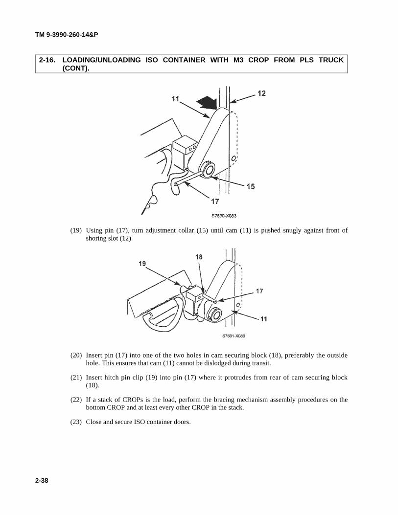
TM 9-3990-260-14&P 2-16. LOADING/UNLOADING ISO CONTAINER WITH M3 CROP FROM PLS TRUCK
(CONT).
(19) Using pin (17), turn adjustment collar (15) until cam (11) is pushed snugly against front of
shoring slot (12).
(20) Insert pin (17) into one of the two holes in cam securing block (18), preferably the outside
hole. This ensures that cam (11) cannot be dislodged during transit.
(21) Insert hitch pin clip (19) into pin (17) where it protrudes from rear of cam securing block (18).
(22) If a stack of CROPs is the load, perform the bracing mechanism assembly procedures on the bottom CROP and at least every other CROP in the stack.
(23) Close and secure ISO container doors.
2-38

TM 9-3990-260-14&P
2-39
b. Unloading.
(1) Open ISO container doors (1) and secure in open position.
NOTESteps (2) through (7) are performed on both bracing mechanisms.
(2) Remove hitch pin clip (19) from pin (17) where it protrudes from rear of cam securing block(18).
(3) Remove pin (17) from the cam securing block (18).
NOTEIt may be necessary to use the hammer (NSN 5120-00-265-7462) from the PLS truck BII to tap thecam securing pin until the adjustment collar can be moved freely.
(4) Using pin (17), turn adjustment collar (15) until cam (11) can be moved freely.(5) Rotate cam (11) out of the shoring slot (12).(6) Insert pin (17) into the cam stowing block (20) under side beam, securing cam (11) in the
stowed position.(7) Insert hitch pin clip (19) into pin where it protrudes from the rear of the cam stowing block
(20) under the side beam. Ensure the hitch pin clip is pointing to the outside of the CROP,toward the ISO container wall.

TM 9-3990-260-14&P
2-40 Change 1
(8) Position ISO container offloading ramps (21) (Appendix G, paragraph G-2) or loadingplatforms (6) (Appendix G, paragraph G-3) on the ground, in front of and against the ISOcontainer door opening so the CROP rollers can roll out of the ISO container and down theoffloading ramps (21) (Appendix G, paragraph G-2) or out of the ISO container and ontothe loading platforms (6) (Appendix G, paragraph G-3).
• Do not stand between the CROPs and the ISO container. Ensure all personnel standclear of CROP when CROP is being moved. Failure to comply may result in severeinjury or death to personnel.
• Exercise extreme caution to prevent contact between the PLS truck hook arm and topof ISO container door opening. Failure to comply can result in damage to ISO con-tainer door frame and/or door latches.
(9) Position PLS truck in front of the ISO container and extend the PLS loading arm. Removethe hook arm extension assembly from the PLS BII storage if the hook arm extension wasnot removed from the rear of the CROP (S/N SC09001 and up) prior to loading (referenceparagraph 2-16.a (2)) or retrieve hook arm assembly from the floor of the ISO container,located in front of the Multipurpose Provision Ring (between the CROP ISO bracingmechanism and the A-frame). Connect the HAE to CROP, engage the PLS hook armassembly to the bail bar of the CROP and lift the front of the CROP (3) approximately 12inches (30 cm) or as high as the load will allow while leaving room between the web strapratchets on top of the load (or deck of the top CROP as shown above) at the ceiling anddoor frame of the ISO container.
2-16. LOADING/UNLOADING ISO CONTAINER WITH M3 CROP FROM PLS TRUCK (CONT).

TM 9-3990-260-14&P
Change 1 2-41
CAUTION
Never pull CROP from ISO container without using offloading ramps (Appendix G, paragraphG-2) or loading platforms (Appendix G, paragraph G-3). Failure to comply will result in dam-age to the CROP.
(10) Drive PLS truck forward a couple of feet, pulling the CROP out of the ISO container.Lower the PLS hook arm until the CROP is resting on the ISO container floor, disconnectthe hook arm extension from the CROP and disconnect the hook arm extension from thehook arm of the PLS. Engage the PLS hook arm to the bail bar of the CROP and lift thefront of the CROP (3) approximately 12 inches (30 cm) or as high as the load will allowwhile leaving room between the web strap ratchets on top of the load (or the deck of the topCROP as shown above) at the ceiling and door frame of the ISO container. Drive PLStruck forward, pulling the CROP out of the ISO container and down the offloading ramps(21) (Appendix G, paragraph G-2) until rollers (2) are grounded or out of the ISO con-tainer and onto the loading platforms (6) (Appendix G, paragraph G-3), leaving CROProllers (2) resting on the loading platforms (6).
(11) Load CROP onto PLS truck. Refer to TM 9-2320-364-10 for procedures to load the CROPonto truck or trailer using the Load Handling System (LHS).

TM 9-3990-260-14&P
2-42 Change 1
2-16. LOADING/UNLOADING ISO CONTAINER WITH M3 CROP FROM PLS TRUCK (CONT).
NOTE If the load is one pallet high or less, an alternative method to steps (8) through (10) may beused, then proceeding with step (11). The alternate method is to pull the CROP until the rollersare approximately 4 feet from the door and load the CROP directly from the ISO container ontothe PLS truck. This method requires caution to ensure the top of the load or web strap ratchetsdo not contact the top of the ISO container door as the CROP is being removed from the ISOcontainer. Additionally, it may be necessary to stop loading, drive the PLS truck backward, andresume loading the CROP, alternately to prevent the CROP from being pulled out of the ISOcontainer and onto the ground, which will damage the rear bumpers.
(12) If the M3 CROP on the bottom of the stack is M3 CROP (S/N SC09001 and up), re-stowthe HAE at the rear of the CROP in the underside stowage location; otherwise, re-stow thehook arm extension in the PLS BII storage.


TM 9-3990-260-14&P
(2-42.1 blank)/2-42.2 Change 1
a. Loading.
• Forklift must be capable of lifting gross weight of loaded CROP. Failure to complymay result in damage to equipment or severe injury or death to personnel. Do notdrive a forklift on the CROP deck; doing so exceeds point load capability of the deck.
• One CROP weighs 3,800 lbs (1,724 kg) and the M3 CROP (S/N SC09001 and up)weighs 3,730 lbs (1,692 kg). Six CROPs weigh 22,800 lbs (10,342 kg) and six M3CROPs (S/N SC09001 and up) weigh 22,380 lbs (10,152 kg). Gross weight of a fullyloaded CROP is 36,250 lbs (16,443 kg). Ensure all personnel stand clear of CROPwhen CROP is being moved. Failure to comply may result in severe injury or death topersonnel.
• Attempting to load a CROP in ISO container requires extreme care to prevent dam-age to equipment. Clearance between the inside of ISO container and each side ofCROP is unusually close.
• Always lift a stack of CROPs by connecting to the bottom CROP. Failure to complymay result in severe injury to personnel or damage to equipment.
• Forklifts are required to have forks a minimum of 68 in. (173 cm) in length. Failure tocomply may result in severe injury to personnel or damage to equipment.
NOTEA stack of six CROPs is maximum that can be loaded into an ISO container.
(1) Prepare ISO container by securing doors (1) in open position.
2-17. LOADING/UNLOADING ISO CONTAINER WITH M3 CROP USING FORKLIFT.

TM 9-3990-260-14&P
(2) With the aid of an assistant, position CROP (2) directly in front of ISO container (3) door opening and using forklift (4) lateral movement, move the CROP laterally until the rollers
are inside the ISO container. Lower the CROP, resting the rollers on the floor of the ISO container and the front of the CROP on the ground.
•• Ensure forklift tines are horizontal or pointed slightly downward to ensure they do not contact crossmembers or the underside of the deck when the tines are being inserted under the CROP or when the CROP is being lifted from the front. Prior to lifting, ensure the tines are in full contact with the front beam and are not contacting cross-members. Failure to comply may result in damage to equipment.
•• Ensure forklift tines are positioned to the outside of the CROP main beams, between the main beams and the multipurpose provisions. Do not attempt to lift front of CROP with forklift tines on the inside of main beams. Failure to comply may result in damage to equipment.
•• Exercise extreme caution to ensure the CROP is properly aligned to be inserted into the ISO container. The CROP is designed with less than 1/2 inch clearance on either side between the CROP and ISO container door frame. Failure to comply may result in damage to equipment.
(3) Reposition the forklift (4) and lift the front of the CROP (2) approximately 12 inches (30 cm) and, with the aid of an assistant, ensure the CROP is carefully aligned for insertion into the ISO container (3).
2-43

TM 9-3990-260-14&P
2-17. LOADING/UNLOADING ISO CONTAINER WITH M3 CROP USING FORKLIFT (CONT).
NOTE
Use forklift lateral movement during insertion to steer CROP into container, exercising caution to ensure CROP remains laterally centered to prevent damage to sides of con-tainer.
(4) Using forklift, lift front of CROP (2) and push it into the ISO container (3) until the CROP rear bumpers (5) fully contact the inside front of the ISO container corner structure (6).
(5) If CROP cannot be pushed into ISO container far enough to engage ISO container front cor-ners because forklift (4) vertical structure (7) will not allow the CROP to go far enough inside the ISO container or the forklift (4) otherwise contacts the container, lower the CROP and reposition forklift (4) approximately 12 inches (30 cm) aft. Insert a 4” X 4” or larger board (8) between the CROP and forklift (4), resting on the forklift tines, to provide suffi-cient range for the forklift to push the CROP into the ISO container until the front corners are fully engaged by the CROP bumpers.
(6) Using forklift lateral movement, ensure CROP is centered laterally in door frame of container.
2-44

TM 9-3990-260-14&P
NOTE
Each of two bracing mechanisms (9) consist of a free-to-rotate cam (10) sandwiched between two collars (11 and 12) welded to a threaded rod (13). The front adjustment collar (12) is equipped with holes, into which a pin (14) can be inserted to provide leverage to turn adjustment collar and adjust cam position fore and aft, enabling it to engage shoring slot (15). The same pin (14) is used to secure the cam after it has been engaged in the shoring slot.
2-45

TM 9-3990-260-14&P 2-17. LOADING/UNLOADING ISO CONTAINER WITH M3 CROP USING FORKLIFT
(CONT).
(7) Rotate cams (10) in two left and right bracing mechanisms until shoring slots (15) on both sides of ISO container are engaged.
(8) If a cam (10) will not engage shoring slot (15), insert pin (14) into adjustment collar (12) and turn, adjusting cam (10) forward or aft until cam (10) will engage shoring slot (15).
NOTE
Depending upon CROP distance from shoring slots, cams will engage in one of two pos-itions depicted above as Nominal Position and Minimum Position. If required, use a fork-lift to position CROP so either the Nominal or Minimum position can be achieved.
2-46

TM 9-3990-260-14&P
2-47
(9) Using pin (14), turn adjustment collar (12) until cam (10) is pushed snugly against front ofshoring slot (15).
(10) Insert pin (14) into one of the two holes in cam securing block (16), preferably the outsidehole. This ensures that cam (10) cannot be dislodged during transit.
(11) Insert hitch pin clip (17) into pin (14) where it protrudes from rear of cam securing block(16).
(12) If a stack of CROPs is the load, perform the bracing mechanism assembly procedures on thebottom CROP and at least every other CROP in the stack.
(13) Close and secure ISO container doors.

TM 9-3990-260-14&P
2-48 Change 1
b. Unloading.
• Forklift must be capable of lifting gross weight of loaded CROP. Failure to complymay result in damage to equipment or severe injury or death to personnel. Do notdrive a forklift on the CROP deck; doing so exceeds point load capability of the deck.
• One M3 CROP weighs 3,800 lbs (1,724 kg) and the M3 CROP (S/N SC09001 andup) weighs 3,730 lbs (1,692 kg). Six M3 CROPs weigh 22,800 lbs (10,342 kg) andsix M3 CROPs (S/N SC09001 and up) weigh 22,380 lbs (10,152 kg). Gross weight ofa fully loaded CROP is 36,250 lbs (16,443 kg). Ensure all personnel stand clear ofCROP when CROP is being moved. Failure to comply may result in severe injury ordeath to personnel.
• Attempting to load a CROP in ISO container requires extreme care to prevent dam-age to equipment. Clearance between the inside of ISO container and each side ofCROP is unusually close.
• Always lift a stack of CROPs by connecting to the bottom CROP. Failure to complymay result in severe injury to personnel or damage to equipment.
• Forklifts are required to have forks a minimum of 68 in. (173 cm) in length. Failure tocomply may result in severe injury to personnel or damage to equipment.
(1) Open ISO container doors (1) and secure in open position.
2-17. LOADING/UNLOADING ISO CONTAINER WITH M3 CROP USING FORKLIFT (CONT).

TM 9-3990-260-14&P
NOTE
Steps (2) through (7) are performed on both bracing mechanisms.
(2) Remove hitch pin clip (17) from pin (14) where it protrudes from rear of cam securing block (16).
(3) Remove pin (14) from the cam securing block (16).
NOTE
It may be necessary to use the hammer (NSN 5120-00-265-7462) from the PLS truck BII to tap the cam securing pin until the adjustment collar can be moved freely.
(4) Using pin (14), tun adjustment collar (12) until cam (10) can be moved freely.
(5) Rotate cam (10) out of the shoring slot.
(6) Insert pin (14) into the cam stowing block (18) under side beam, securing cam (10) in the stowed position.
(7) Insert hitch pin clip (17) into pin where it protrudes from rear of cam stowing block (18) under the side beam. Ensure the hitch pin clip is pointing to the outside of the CROP, toward the ISO container wall.
2-49

TM 9-3990-260-14&P
2-17. LOADING/UNLOADING ISO CONTAINER WITH M3 CROP USING FORKLIFT
(CONT).
• Ensure forklift tines are horizontal or pointed slightly downward to ensure they do not
contact crossmembers or the underside of the deck when the tines are being inserted under the CROP or when the CROP is being lifted from the front. Prior to lifting, ensure the tines are in full contact with the front beam and are not contacting cross-members. Failure to comply may result in damage to equipment.
• Ensure forklift tines are positioned to the outside of the CROP main beams, between the main beams and the multipurpose provisions. Do not attempt to lift front of CROP with forklift tines on the inside of main beams. Failure to comply may result in dam-age to equipment.
(8) Engage front of CROP with forklift.
NOTE
Obtain chain(s) from PLS truck(s) BII for use with the following steps.
(9) Attach chain(s) (19) from two CROP front multipurpose provision rings (20) to forklift.
(10) Lift front of CROP 3-5 inches (8-13 cm), or as much as the load will allow up to 18 inches (46 cm).
(11) Drive forklift in reverse and pull CROP until rollers are approximately 10 inches (25 cm) from door opening of ISO container.
(12) Lower CROP, resting the front of the CROP on the ground.
(13) Remove chains(s) (19) from CROP and forklift.
(14) Reposition forklift and lift CROP from side, using forklift pockets in CROP main beams.
(15) Using forklift lateral movement, remove CROP from ISO container.
2-50

TM 9-3990-260-14&P
Change 1 2-51
a. Preparation for Storage. (1) Refer to AR 750-1 for administrative storage procedures. If short-term storage is indi-
cated, go to Step (2).
• Solvent cleaning compound (MIL-PRF-680) can cause eye and skin irritation. Wear pro-tective rubber gloves and chemical splash goggles or faceshield to avoid skin or eye con-tact. Use in a well ventilated area. First aid for skin contact: remove any contaminatedclothing and wash skin thoroughly with soap and water. First aid for eye contact: flushwith water for 15 minutes or until irritation subsides. If irritation persists, call a physi-cian. If overcome by vapors, move from exposed area and call a physician. In case ofingestion, do not induce vomiting, call a physician immediately.
(2) Use solvent cleaning compound (Item 3, Appendix E) to clean or wash grease or oil fromall metal parts. All surfaces must be clean to ensure removal of corrosion, soil, grease orresidues.
(3) After cleaning, use cold water to rinse CROP. Dry all parts thoroughly with a lint-free cloth(Item 1, Appendix E).
(4) Perform the Preventive Maintenance Checks and Services in Tables 2-1 and 4-1. (5) Refer to Appendix J and perform all lubrication procedures. (6) Schedule the next PMCS on DD Form 314, Preventive Maintenance Schedule and Record. (7) Report all deficiencies on DA Form 2407 if the deficiencies appear to involve unsatisfac-
tory design. (8) Spot paint all surfaces as necessary (TB 43-0209).
b. Preparation for Shipment. (1) Complete storage instructions according to paragraph 2-18 a. Preparation for Storage,
above. (2) Refer to AR 746-80 for Marking of Supplies for Shipment. (3) Refer to AR 725-5 and prepare all shipping documents to accompany CROP. (4) Refer to TB 9-2300-281-35, Standards for Overseas Shipment or Domestic Issue of Spe-
cial Purpose Vehicles, if CROP is to be shipped overseas.
2-18. PREPARATION FOR STORAGE OR SHIPMENT.

TM 9-3990-260-14&P
2-52 Change 1
a. Stencils. The word “LIFT” is stenciled at six places on CROP, two on each side and two in thefront. The word “CARC” is stenciled on right front of front beam. The words “NO LIFT” are stenciled on the angleiron brace at the bottom of the end structure assembly.
b. Identification and Shipping Data Plates. Refer to Figure 2-2 for location and descrip-tion of plates.
NOTEThe identification plate weight changes for the M3 CROP (S/N SC09001 and up) are as follows:
TARE WEIGHT = 3,730 LB (1,692 KG)PAYLOAD WEIGHT = 32,520 LB (14,751 KG)
Figure 2-2. Location and Description of Decals and Instruction Plates
Item Description 1 Forklift fork insertion lift points, side. 2 Forklift fork insertion lift points, front. 3 Identification Plate. 4 Shipping Plate. 5 “No Lift” point.
2-19. M3 CROP DECALS AND INSTRUCTION PLATES.

TM 9-3990-260-14&P
CHAPTER 3
OPERATOR MAINTENANCE INSTRUCTIONS (M3 CROP)
Para Contents Page
3-1 Troubleshooting Introduction ..................................................................................................... 3-1 3-2 M3 CROP Troub1eshooting Symptoms...................................................................................... 3-1 3-3 Maintenance Introduction............................................................................................................ 3-4
Section I. TROUBLESHOOTING PROCEDURES
3-1. TROUBLESHOOTING INTRODUCTION.
This section contains step by step procedures for identifying, locating and isolating equipment malfunctions.
3-2. M3 CROP TROUBLESHOOTING SYMPTOMS.
Refer to Table 3-1 for a list of Troubleshooting Symptoms. Table 3-2 lists the most common troubleshooting proce- dures found during operation or maintenance of the M3 CROP. Tests or inspections and corrective actions should be performed in the order listed. If a malfunction is not listed or is not corrected by listed corrective actions, notify the supervisor.
Table 3-1. Operator Troubleshooting Symptom Index
Troubleshooting Procedure Page
1. End Structure Assembly (A-Frame) lowers too rapidly (too heavy) ........................................ 3-2 2. For rail transport, M3 CROP does not load on PLS truck properly because the rail transport locking pin holes do not line up correctly ................................................................. 3-3
3-1

TM 9-3990-260-14&P
3-2. M3 CROP TROUBLESHOOTING SYMPTOMS (CONT).
Table 3-2. Operator Troubleshooting Procedures
MALFUNCTION TEST OR INSPECTIONS CORRECTIVE ACTION
1. END STRUCTURE ASSEMBLY (A-FRAME) LOWERS TOO RAPIDLY (TOO HEAVY).
• End structure assembly dead weight is beyond two-man lift limit. The end structure assembly is equipped with a rear pin and castle nut which secures the end structure and serves as a friction device which aids in lowering the end structure assembly.
• Lowering operations must by conducted on level ground.
• Do not stand under end structure assembly when raising or lowering.
• Use an assistant when raising or lowering the end structure assembly to prevent seri- ous injury to personnel.
Is one or both rear pins loose or missing the castle nut or cotter pin?
• If the rear pin assembly is loose, tighten each rear pin by inserting the BII pin tight- ening rod through the hole in the end of each pin and turning the castle nut clock- wise using the BII 2 ¼" socket and socket wrench. Tighten the castle nut until it presses firmly against the lock washer and the split in the lock washer is fully com- pressed. Turn the castle nut a further 1/4 to 3/4 turn. Do not bend the tightening rod by attempting to turn the rear pins using the tightening rod. Use the 2 ¼" socket and socket wrench to turn the castle nut. The tightening rod is used to keep the rear pin from turning during the tightening procedure.
• If the castle nut or cotter pin is missing, contact unit maintenance.
3-2

TM 9-3990-260-14&P
Table 3-2. Operator Troubleshooting Procedures - (Cont)
MALFUNCTION TEST OR INSPECTIONS CORRECTIVE ACTION
2. FOR RAIL TRANSPORT, M3 CROP DOES NOT LOAD ON PLS TRUCK PROPERLY BECAUSE THE RAIL TRANSPORT LOCKING PIN HOLES DO NOT LINE UP CORRECTLY.
Is one or both rear pins loose or missing the castle nut?
• If the rear pin assembly is loose, tighten each rear pin by inserting the BII pin tight- ening rod through the hole in the end of each pin and turning the castle nut clock- wise using the BII 2 ¼” socket and socket wrench. Tighten the castle nut until it presses firmly against the lock washer and the split in the lock washer is fully com- pressed. Turn the castle nut a further 1/4 to 3/4 turn. Do not bend the tightening rod by attempting to turn the rear pins using the tightening rod. Use the 2 ¼” socket and socket wrench to turn the castle nut. The tightening rod is used to keep the rear pin from turning during the tightening procedure.
• If the castle nut or cotter pin is missing, contact unit maintenance.
Is one or both front pin assemblies loose or missing the castle nut?
• If the front pin assembly is loose, tighten each front pin by inserting the BII pin tightening rod through the hole in the end of each pin and turning the castle nut clockwise using the BII2 ¼” socket and socket wrench. Tighten the castle nut until it presses firmly against the lock washer and the split in the lock washer is fully compressed. Turn the castle nut a further 1/4 to 3/4 turn. Do not bend the tightening rod by attempting to turn the front pins using the tightening rod. Use the 2 ¼” socket and socket wrench to turn the castle nut. The tightening rod is used to keep the front pin from turning during the tightening procedure.
• If the castle nut or hitch pin clip is missing, contact unit maintenance.
Is end structure assembly frame or bail bar bent?
• If the end structure assembly frame or bail bar is suspected of being bent, contact unit maintenance.
3-3

TM 9-3990-260-14&P
Section II. MAINTENANCE INSTRUCTIONS.
3-3. MAINTENANCE INTRODUCTION.
Maintenance procedures for the replacement or repair of the end structure assembly, twistlocks, bracing mecha- nisms, and rollers are covered in Chapter 4.
3-4

TM 9-3990-260-14&P
4-1
CHAPTER 4
UNIT MAINTENANCE INSTRUCTIONS(M3 CROP)
Para Contents Page
4-1. Common Tools and Equipment . . . . . . . . . . . . . . . . . . . . . . . . . . . . . . . . . . . . . . . . . . . . . . . . . . . . . . . . 4-14-2. Special Tools, TMDE and Support Equipment . . . . . . . . . . . . . . . . . . . . . . . . . . . . . . . . . . . . . . . . . . . . 4-14-3. Repair Parts . . . . . . . . . . . . . . . . . . . . . . . . . . . . . . . . . . . . . . . . . . . . . . . . . . . . . . . . . . . . . . . . . . . . . . . . 4-24-4. Unpacking and Packing . . . . . . . . . . . . . . . . . . . . . . . . . . . . . . . . . . . . . . . . . . . . . . . . . . . . . . . . . . . . . . 4-24-5. Lubrication . . . . . . . . . . . . . . . . . . . . . . . . . . . . . . . . . . . . . . . . . . . . . . . . . . . . . . . . . . . . . . . . . . . . . . . . 4-34-6. Hand Receipt . . . . . . . . . . . . . . . . . . . . . . . . . . . . . . . . . . . . . . . . . . . . . . . . . . . . . . . . . . . . . . . . . . . . . . 4-34-7. Introduction (PMCS) . . . . . . . . . . . . . . . . . . . . . . . . . . . . . . . . . . . . . . . . . . . . . . . . . . . . . . . . . . . . . . . . 4-44-8. Unit PMCS Procedures . . . . . . . . . . . . . . . . . . . . . . . . . . . . . . . . . . . . . . . . . . . . . . . . . . . . . . . . . . . . . . . 4-44-9. PMCS Table Explanation . . . . . . . . . . . . . . . . . . . . . . . . . . . . . . . . . . . . . . . . . . . . . . . . . . . . . . . . . . . . . 4-54-10. Introduction (Unit Maintenance Procedures) . . . . . . . . . . . . . . . . . . . . . . . . . . . . . . . . . . . . . . . . . . . . . . 4-124-11. General Maintenance Instructions . . . . . . . . . . . . . . . . . . . . . . . . . . . . . . . . . . . . . . . . . . . . . . . . . . . . . . 4-124-12. End Structure Assembly (A-Frame) Replacement . . . . . . . . . . . . . . . . . . . . . . . . . . . . . . . . . . . . . . . . . . 4-144-13. Twistlock Replacement . . . . . . . . . . . . . . . . . . . . . . . . . . . . . . . . . . . . . . . . . . . . . . . . . . . . . . . . . . . . . . 4-184-14. Roller Replacement . . . . . . . . . . . . . . . . . . . . . . . . . . . . . . . . . . . . . . . . . . . . . . . . . . . . . . . . . . . . . . . . . 4-204-15. Bracing Mechanism Replacement . . . . . . . . . . . . . . . . . . . . . . . . . . . . . . . . . . . . . . . . . . . . . . . . . . . . . . 4-224-16. Stowage Box Door Maintenance . . . . . . . . . . . . . . . . . . . . . . . . . . . . . . . . . . . . . . . . . . . . . . . . . . . . . . . 4-23
Section I. REPAIR PARTS, SPECIAL TOOLS, TEST, MEASUREMENT AND DIAGNOSTIC EQUIPMENT (TMDE) AND SUPPORT EQUIPMENT
For authorized common tools and equipment, refer to the Modified Table of Organization and Equipment (MTOE)applicable to your unit.
Refer to Appendix B, the Maintenance Allocation Chart (MAC) and Appendix F, Repair Parts and Special ToolsList (RPSTL), to determine special tools, TMDE and support equipment for the M3 CROP. No fabricated tools areneeded.
A trailer interface kit, consisting of metal spacers, is utilized for loading CROP on the PLS trailer. These spacersare required because the CROP is shorter than the M1077 and M1077A1 Flatracks. The spacers are part of thetrailer, hence do not appear in this document.
If a CROP is pulled from an ISO container and is allowed to drop directly to the ground prior to loading on the PLStruck, the rear bumpers can suffer damage. To preclude this, the use of ramps or platforms placed at the front of theISO container is encouraged. Directions for the manufacture of these items may be found at Appendix G.
4-1. COMMON TOOLS AND EQUIPMENT.
4-2. SPECIAL TOOLS, TMDE AND SUPPORT EQUIPMENT.
TM 9-3990-260-14&P
4-2 Change 1
Repair parts are listed and illustrated in the Repair Parts and Special Tools List (RPSTL), Appendix F, covering Unit andDirect Support Maintenance for the M3 CROP.
Section II. SERVICE UPON RECEIPT
This paragraph provides information required to ensure the M3 CROP is adequately inspected, serviced and operationallytested before it is subjected to normal everyday use. The procedures cover unpacking, deprocessing and packing.
a. Unpacking. (1) Remove any metal strapping, plywood, tapes, seals, wrapping or any other shipping and
protective items.
• Solvent cleaning compound (MIL-PRF-680) can cause eye and skin irritation. Wearprotective rubber gloves and chemical splash goggles or faceshield to avoid skin oreye contact. Use in a well ventilated area. First aid for skin contact: remove any con-taminated clothing and wash skin thoroughly with soap and water. First aid for eyecontact: flush with water for 15 minutes or until irritation subsides. If irritation per-sists, call a physician. If overcome by vapors, move from exposed area and call a phy-sician. In case of ingestion, do not induce vomiting, call a physician immediately.
(2) If any parts other than those shown in the lubrication order are coated with lubricating oilor grease, remove with solvent cleaning compound (Item 3, Appendix E).
(3) Inspect M3 CROP for damage incurred during shipping. If M3 CROP has been damaged,report the damage.
(4) Check the equipment against the packing slip to ensure shipment is complete. Report alldiscrepancies in accordance with DA PAM 750-8.
b. Servicing. (1) Perform the Preventive Maintenance Checks and Services (PMCS) in Tables 2-1 and 4-1. (2) Schedule the next PMCS on DD Form 314, Preventive Maintenance Schedule and Record. (3) Report all deficiencies on DA Form 2407 if the deficiencies appear to involve unsatisfac-
tory design.
c. Packing. Preservation and other protective measures taken in the preparation of material andaccompanying tools and equipment for shipment must be sufficient to protect the material against deterioration andphysical damage during shipment.
4-3. REPAIR PARTS.
4-4. UNPACKING AND PACKING.

TM 9-3990-260-14&P
Change 1 4-3
• Solvent cleaning compound (MIL-PRF-680) can cause eye and skin irritation. Wearprotective rubber gloves and chemical splash goggles or faceshield to avoid skin oreye contact. Use in a well ventilated area. First aid for skin contact: remove any con-taminated clothing and wash skin thoroughly with soap and water. First aid for eyecontact: flush with water for 15 minutes or until irritation subsides. If irritation per-sists, call a physician. If overcome by vapors, move from exposed area and call a phy-sician. In case of ingestion, do not induce vomiting, call a physician immediately.
(1) Use solvent cleaning compound (Item 3, Appendix E) to clean or wash grease or oil fromall metal parts. All surfaces must be clean to ensure removal of corrosion, soil, grease orresidues.
(2) After cleaning, use cold water to rinse M3 CROP. Dry all parts thoroughly with a lint-freecloth (Item 1, Appendix E).
(3) Lubricate according to procedures at Appendix J. (4) Spot paint all surfaces as necessary (TB 43-0209).
Refer to Appendix J for lubrication instructions pertaining to the M3 CROP.
Refer to Appendix C, Components of End Item (COEI) and Basic Issue Items (BII) Lists for proper inventory and controlprocedures.
4-5. LUBRICATION.
4-6. HAND RECEIPT.

TM 9-3990-260-14&P
4-4 Change 1
Section III. UNIT MAINTENANCE PREVENTIVE MAINTENANCECHECKS AND SERVICES (PMCS)
This section presents Unit Maintenance checks and services. Figure 4-1 illustrates the route to use in completingthe PMCS procedures. Table 4-1 provides PMCS procedures. Unit Maintenance should also perform OperatorPMCS (paragraph 2-1).
Figure 4-1. PMCS Walk-Around
a. Always perform your preventive maintenance in the same order, so it gets to be a habit. Once youhave some practice, you will spot anything wrong in a hurry.
b. If something looks wrong and you can not fix it, write it down on DA Form 2404.
• Solvent cleaning compound (MIL-PRF-680) can cause eye and skin irritation. Wearprotective rubber gloves and chemical splash goggles or faceshield to avoid skin oreye contact. Use in a well ventilated area. First aid for skin contact: remove any con-taminated clothing and wash skin thoroughly with soap and water. First aid for eyecontact: flush with water for 15 minutes or until irritation subsides. If irritation per-sists, call a physician. If overcome by vapors, move from exposed area and call a phy-sician. In case of ingestion, do not induce vomiting, call a physician immediately.
4-7. INTRODUCTION.
4-8. UNIT PMCS PROCEDURES.

TM 9-3990-260-14&P
Change 1 4-5
c. Clean as you work and as needed. Dirt, grease, oil and debris may get in the way and cover up aproblem. Use solvent cleaning compound (Item 3, Appendix E) to clean M3 CROP where dirt, grease or oil hasaccumulated.
d. Check for missing, loose, bent or broken bolts, deck fasteners, nuts and screws. Look for chippedpaint, bare metal or rust around bolt heads. Tighten loose parts.
e. Look for loose paint, rust or gaps where parts are welded together. If you find a bad weld, report itto Direct Support Maintenance.
f. If cracks are detected, notify Direct Support Maintenance to perform further inspection.
a. Do the SEMIANNUAL PREVENTIVE MAINTENANCE (Table 4-1) once every six months.
b. Always do the Preventive Maintenance in the same order until it gets to be a habit. Once practiced,it will be easy to spot anything wrong in a hurry.
c. If anything looks wrong and is not fixed, write it on a DA Form 2404.
d. When doing Preventive Maintenance, take along the tools and supplies needed to make all thechecks, including a clean cloth or two.
e. The following is a breakdown of the PMCS table:
(1) “Item No.” column. Checks and services are numbered in a logical order for moving aroundthe M3 CROP. The item number column is used as a source of items numbers for the TMNumber Column on DA Form 2404, Equipment Inspection and Maintenance Worksheet, forrecording results of the PMCS.
(2) “Interval” column. This column identifies when the PMCS should be performed. (3) “Item To Check/Service” column. This column identifies the item to be checked/serviced. (4) “Procedure” column. This column contains all the information required to do the check/
inspection. (5) “Not Mission Capable If:” column. This column contains a brief statement of the condition
(e.g., malfunction, shortage) that would cause the M3 CROP to be less than fully ready toperform its assigned mission.
4-9. PMCS TABLE EXPLANATION.

TM 9-3990-260-14&P
4-6
Table 4-1. Unit Maintenance Preventive Maintenance Checks and Services
Item No. Interval
LocationItem toCheck/Service Procedure Not Fully Mission
Capable If:
1 Semi-Annually
M3 CROP Primary Structural Components
Visually inspect all parts of the main beams (1), lateral (2) and cross members (3), and side and end beams for:
Any part of the main beams, lateral and cross members, or side and end beams have:
a. A dent or bend that is greater than 3/4 inch (19 mm) in depth.
a. A dent or bend greater than 3/4 inch (19 mm) in depth.
b. A crack, break, cut, tear, puncture or corrosive failure.
b. A crack, break, cut, tear, puncture or corrosive failure.
c. A missing, cracked or broken weld at the juncture between any primary component.
c. A missing, cracked or broken weld.

TM 9-3990-260-14&P
Table 4-1. Unit Maintenance Preventive Maintenance Checks and Services - Continued
Item No.
Interval
Location Item to
Check/Service
Procedure
Not Fully Mission
Capable If:
2 Semi- Annually
M3 CROP Bail Bar
Check bar and notify supervisor:
a. If wear at lower back side bar (4) is greater than 1/4 in. (6.35 mm).
Wear found exceeds specification.
b. If wear at bottom of bar (5) is greater than 1/8 in. (3.175 mm).
3 Semi- Annually
Bracing Mechanisms
a. Ensure cams (6) are not bent or broken so they will not engage the shor- ing slot.
a. Cam is broken or so bent it cannot be engaged in the shoring slot.
b. Ensure securing pins (7) and spring pin clips (8) are available and secured by lanyard.
b. Securing pin or spring pin clip, is miss- ing.
c. Ensure threaded shaft (9) can be turned both in and out tightening and loosening the cam in the shoring slot.
c. Threaded shaft is bent, jammed, or other- wise cannot be turned both in and out.
Bail bar may have metal slivers or sharp edges. Wear gloves if handling or injury to personnel could result.
4-7

TM 9-3990-260-14&P
Table 4-1. Unit Maintenance Preventive Maintenance Checks and Services - Continued
Item No.
Interval
Location Item to Check/Service
Procedure
Not Fully Mission Capable If:
3 (Cont)
Semi- Annually
Bracing Mechanisms
d. Ensure each securing pin can be inserted through its cam and cam can be properly secured.
d. Cam securing pin hole is deformed or pin cannot otherwise be inserted through cam and properly secured.
4 Semi- Annually
M3 CROP Twistlocks
Visually inspect twistlocks to ensure:
a. The shaft (10) is straight and not cracked or broken.
a. Shaft is broken.
b. Handle (11) is securely fastened to shaft.
b. Handle is missing.
c. Shear pin (12) is secure. c. Shear pin is miss- ing.
d. Head (13) is not broken or cracked. d. Head is broken, cracked or missing.
e. Twistlock can be locked and unlocked correctly without undue diffi- culty.
e. Twistlock cannot be locked or unlocked by hand.
f. No crack greater than 3/4 inch (19 mm) exists in the welds or parent mate- rial of the twistlock housing.
f. Twist lock housing welds or parent material contains a crack greater .than 3/4 inch (19 mm).
4-8

TM 9-3990-260-14&P
Table 4-1. Unit Maintenance Preventive Maintenance Checks and Services -Continued Item No.
Interval
Location Item to Check/Service
Procedure
Not Fully Mission Capable If:
5 Semi- Annually
End Structure Assembly
a. Ensure two front (14) and rear pins (15) are not bent, galled, cracked, cor- roded, or stripped so they do not seat properly or cannot be sufficiently tight- ened.
a. Front or rear pin(s) bent, galled, cracked, corroded, or stripped so they do not seat properly or cannot be sufficiently tightened.
b. Visually inspect all welds and par- ent material for cracks.
b. Parent material or weld is cracked.
c. Ensure end structure assembly tubular frame (16) is not bent, prevent- ing it from loading correctly on a PLS truck.
c. End structure assembly tubular frame is bent, preventing CROP from loading cor- rectly on PLS truck.
6 Semi- Annually
Rollers a. Inspect exterior of roller (17) to ensure it is not broken or so defaced that it does roll properly.
b. Inspect center roller next to shaft to ensure it is not worn more than 1/4 inch (6.4 mm) between bushing and roller material (if bushing is not present).
a. Roller is broken or so defaced that it does not roll properly.
b. Center of roller exceeds wear criteria.
c. Ensure shaft (18) is straight, with all hardware attached.
c. Shaft is bent so roller will not roll or hardware is missing so roller can detach.
4-9

TM 9-3990-260-14&P
Table 4-1. Unit Maintenance Preventive Maintenance Checks and Services - Continued
Item No.
Interval
Location Item to Check/Service
Procedure
Not Fully Mission Capable If:
6 (Cont)
Semi- Annually
Rollers d. Head of shaft (toward center of CROP) has at least 1/8 inch (3.2 mm) of material.
d. Head of shaft exceeds wear criteria.
7 Semi- Annually
Tiedowns (D- rings) and Multi- purpose Provisions
a. Visually inspect to ensure welds (19) securing bar to inside and outside of side beam are not cracked or side beam is not distorted or cracked.
a. Welds are broken, bar is loose, or side beam is cracked.
b. Visually inspect to ensure tiedown (D-ring) (20) and bar (21) are not miss- ing, cracked, or deformed.
b. Any two adjacent (side by side) tiedowns or bars are missing.
c. Inspect to ensure web strap can be attached to tiedown (D-ring) and bar.
c. Web strap cannot be attached.
d. Visually inspect multipurpose pro- visions and mounting brackets for cracks.
d. Multipurpose provi- sion or mounting bracket is cracked.
4-10

TM 9-3990-260-14&P
Table 4-1. Unit Maintenance Preventive Maintenance Checks and Services -Continued Item No.
Interval
Location Item to Check/Service
Procedure
Not Fully Mission Capable If:
8 Semi- Annually
Stowage Box Doors
a. Ensure door (23) lays flat and is not bent or broken. b. Ensure latch assembly (22) oper- ates correctly and can be secured with padlock. c. Ensure hinges operate so door can be opened and closed.
a. Door is broken, bent, or will not lay flat. b. Latch is inoperable or otherwise cannot be locked. c. Hinges are broken or so damaged that door cannot be opened or closed.
4-11

TM 9-3990-260-14&P
SECTION IV. UNIT MAINTENANCE PROCEDURES
4-10. INTRODUTION (UNIT MAINTENANCE PROCEDURES).
This section presents Unit Maintenance procedures for the M3 CROP. These procedures may include servicing, hoisting, inspection, cleaning, removal and disassembly, inspection, assembly, and installation and any procedures needed for placing the M3 CROP or its components into service.
4-11. GENERAL MAINTENANCE INSTRUCTIONS.
a. Servicing. The M3 CROP requires only lubrication and cleaning as service.
b. Hoisting Loaded M3 CROP.
M3 CROP and load weigh up to 36,250 lbs (16443 kg). Loaded M3 CROP on PLS truck or trailer must not exceed 36,250 lbs (16443 kg). Attach suitable lifting device to avoid serious injury or death to personnel.
(1) For other than ordinary operation, M3 CROP must be lifted with a forklift or other lifting device. The M3 CROP is loaded on and off the Palletized Load System (PLS) Truck or the PLS Trailer using the Load Handling System (LHS). Refer to TM 9-2320-364-10.
CAUTION
Do not load or unload M3 CROP with loose cargo or damage to equipment or cargo may result.
(2) Install web straps before lifting any load. (3) When lifting a loaded M3 CROP using multipurpose provision rings located at front and rear
of M3 CROP, use a spreader bar if necessary to avoid damage to load. c. Inspection of Installed Parts. Perform inspection with the item in its normally installed posi-
tion or condition, considering accessibility and visibility of the item being inspected. The purpose of the inspection is to determine if the item is damaged or incomplete to the extent that it should be replaced/repaired.
(1) Inspect for loose, missing or damaged parts. (2) Inspect parts for dents, holes, worn spots, scratches, marred finish, cracks, rust and corro-
sion. (3) Look for loose or chipped paint, rust or gaps where parts are welded together. If a bad weld
is found, notify your supervisor.
4-12

TM 9-3990-260-14&P
Change 1 4-13
• Solvent cleaning compound (MIL-PRF-680) can cause eye and skin irritation. Wearprotective rubber gloves and chemical splash goggles or faceshield to avoid skin or eyecontact. Use in a well ventilated area. First aid for skin contact: remove any contami-nated clothing and wash skin thoroughly with soap and water. First aid for eye contact:flush with water for 15 minutes or until irritation subsides. If irritation persists, call aphysician. If overcome by vapors, move from exposed area and call a physician. In caseof ingestion, do not induce vomiting, call a physician immediately.
d. Cleaning. Remove buildup of dirt and grease by wiping with a cloth (Item 1, Appendix E). Use acloth or wire scratch brush (Item 1, Appendix I) and solvent cleaning compound (Item 3, Appendix E) to clean metalparts. Allow to dry.
e. Removal. During removal process, tag (Item 4, Appendix E) similar parts for ease of installation.
f. Disassembly. During disassembly, tag (Item 4, Appendix E) similar parts for ease of assembly.
g. Inspection - Acceptance/Rejection Criteria. Verify that repaired or used components con-form to the wear limits, fits and tolerances established.
h. Painting. M3 CROPs are delivered painted with one color, CARC Green 383. For other missionrequirements, refer to TB 43-0209, Color, Marking, and Camouflage Painting of Military Vehicles, ConstructionEquipment and Material Handling Equipment.
i. Lubrication. Lubrication instructions are contained in Appendix J.
j. Assembly. M3 CROPs are delivered fully assembled.
k. Adjustment. M3 CROP requires no adjustments prior to use or as scheduled maintenance.

TM 9-3990-260-14&P
4-14
4-12. END STRUCTURE ASSEMBLY (A-FRAME) REPLACEMENT.
This task covers:
a. Removal b. Installation c. Follow-on Maintenance
INITIAL SETUP
Tools and Special Tools Tool Kit, General Mechanic’s: Automotive (Item 5, Appendix I). Lifting Device [minimum capability 400 lbs(181 kg)].
Material and Parts Lock Washer (4 ea.), Appendix H, Table H-1,Item 7. Lock Nut (2 ea.), Appendix H, Table H-1, Item 1. Cotter Pin (2 ea.), Appendix H, Table H-1, Item 4.
Grease, GAA (Item 2, Appendix E).
Personnel Required Two.
Equipment Condition M3 CROP unloaded to ground.

TM 9-3990-260-14&P
Change 1 4-15
a. Removal.
End structure assembly weighs 370 lbs (168 kg). Raising and lowering must be conductedon level ground. Use the aid of a suitable lifting device when raising or lowering end struc-ture assembly to prevent serious injury or death to personnel.
(1) Ensure end structure assembly is in the upright position. (2) Attach lifting device to end structure assembly bail bar (1). (3) Raise the lifting device until lifting device hook and bail bar (1) are engaged, but no
upward pressure is being applied to bail bar (1).
NOTE A tether is no longer used to secure hitch pin clips on later model CROPs. (4) Remove hitch pin clips (2) from two front pins (3). (5) Remove pin tightening rod (4), 2-1/4 inch socket (5), socket wrench (6), and hammer (7)
from CROP stowage boxes or from the front storage areas on the M3 CROP (S/N SC09001 and up).
(6) Using pin tightening rod (4), 2-1/4 inch socket (5), socket wrench (6), and hammer (7)remove castle nuts (8), lock washers (9), and front pins (3) from end structure assembly.Discard lock washers (9).
The end structure assembly must be securely held by the assistant to ensure it does not shiftafter the last rear pin is removed. Failure to comply could result in injury to personnel.
(7) Using assistant and lifting device, relieve pressure from rear pins (10).
NOTE The removal of the rear pins may require shaking the end structure or slight movement up ordown of the lifting device to relieve pressure and correctly align holes in pin block and pin sup-port plate enabling the rear pins to be removed.
(8) With the assistant holding the end structure assembly to prevent movement, remove twocotter pins (11), two castle nuts (8), two lock washers (9) and two rear pins (10). Discardcotter pins (11).
(9) Lift and remove the end structure assembly using the lifting device.
NOTE • Perform the following steps for the left or right end structure spacers. • Note the positioning of spacers prior to removal, to aid in assembly. • It is not necessary to remove the spacers unless excessively worn or damaged.

TM 9-3990-260-14&P
4-16 Change 1
4-12. END STRUCTURE ASSEMBLY (A-FRAME) REPLACEMENT (CONT).
(10) Remove lock nut (14), flat washer (15), and screw (16) securing the spacer (17). Discardlock nut.
(11) Remove spacer (17) from pin support plate (12).
b. Installation.
End structure assembly weighs 370 lbs (168 kg). Raising and lowering must be conductedon level ground. Use the aid of a suitable lifting device when raising or lowering end struc-ture assembly to prevent serious injury or death to personnel.
NOTE • Perform steps (1) and (2) only if left and right spacers have been removed. • Perform the following steps for the left or right end structure spacers. • Spacers should be replaced as set.

TM 9-3990-260-14&P
Change 1 4-17
(1) Position spacer (17) on pin support plate (12). (2) Secure spacer (17) in place with screw (16), flat washer (15), and new lock nut (14). (3) Attach lifting device to end structure assembly bail bar (1). (4) Check the end structure assembly pin support plates (12 and 13) to ensure that the holes
where the front and rear pins (3 and 10) will be inserted and the front and rear pins (3 and10) are clean and completely free of dirt, sand, or other contamination.
(5) Apply a light film of grease (GAA) to rear pins (10). (6) Using lifting device, position end structure assembly and insert two rear pins (10) through
the pin support plates (12 and 13). Install lock washers (9) and castle nuts (8) finger tight. (7) Apply a light film of grease (GAA) to front pins (3). (8) Using assistant and lifting device, position end structure assembly and insert two front pins
(3) through the pin support plates (12 and 13). Install lock washers (9) and castle nuts (8)finger tight.
(9) While holding front pins (3) with pin tightening tool (4), tighten castle nut (8) clockwiseusing the socket wrench (6) with 2-1/4 inch socket (5). Ensure the end structure assemblyis centered between support plates (12 and 13) by alternately tightening each castle nut (8).Ensure the split in each lock washer is compressed and the nuts are firmly tightened usingfull arm strength only. Do not over tighten by standing on the socket wrench, using yourfeet to push against the socket wrench, or using other leverage gaining means such as a“cheater bar or pipe.” Do not use pin tightening rod to turn front pins. Use the socket andwrench to tighten castle nuts.
(10) While holding rear pins (10) with pin tightening tool (4), tighten castle nut (8) clockwiseusing the socket wrench (6) and 2-1/4 inch socket (5). Ensure the split in each lock washeris compressed and the nuts are firmly tightened using full arm strength only. Do not overtighten by standing on the socket wrench, using your feet to push against the socketwrench, or using other leverage gaining means such as a “cheater bar or pipe.” Do not usepin tightening rod to turn rear pins. Use the socket and wrench to tighten castle nuts.
(11) Secure castle nuts on both rear pins using new cotter pins (11).
NOTE A tether is no longer used to secure hitch pin clips on later model CROPs.
(12) Secure castle nuts on both front pins using hitch pin clips (2). (13) Disconnect and remove lifting device. (14) Return the pin tightening rod (4), 2-1/4 inch socket (5), socket wrench (6), and hammer (7)
to the CROP stowage boxes or into the front storage areas on the M3 CROP (S/N SC09001and up).
c. Follow-on Maintenance. None.

TM 9-3990-260-14&P
4-18
4-13. TWISTLOCK REPLACEMENT.
This task covers:
a. Removal b. Installation c. Follow-on Maintenance
INITIAL SETUP
Tools and Special Tools
Tool Kit, General Mechanic’s: Automotive (Item 5, Appendix I).
Material and Parts
Lock Nut (2 ea.), Appendix H, Table H-1, Item 1.
Grease, GAA (Item 2, Appendix E).

TM 9-3990-260-14&P
a. Removal.
NOTE This procedure shows replacement of one twistlock. Replacement is the same for all four twistlocks.
(1) Remove lock nut (1) from handle bolt (2). Remove the handle bolt (2) and handle (3) from twistlock (4). Discard lock nut.
(2) Remove lock nut (1) from shear pin bolt (5). Remove the shear pin bolt (5) and shear pin (6). Discard lock nut.
(3) Remove the twistlock (4) by pushing it up and out of the twistlock housing (7).
b. Installation.
NOTE Ensure the replacement twistlock is the correct type. There are two types of twistlocks. One type is used with the right front and left rear twistlocks, the other with the left front and right rear twistlocks.
(1) Insert twistlock (4) into twistlock housing (7).
(2) Install shear pin (6), shear pin bolt (5), and lock nut (1). Tighten lock nut (1).
(3) Install handle (3), handle bolt (2), and lock nut (1). Tighten lock nut (1).
c. Follow-on Maintenance.
• Lubricate grease fitting in accordance with Appendix J.
4-19
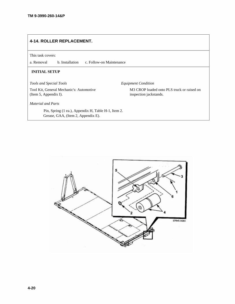
TM 9-3990-260-14&P
4-14. ROLLER REPLACEMENT.
This task covers:
a. Removal b. Installation c. Follow-on Maintenance
INITIAL SETUP
Tools and Special Tools Equipment Condition
Tool Kit, General Mechanic's: Automotive M3 CROP loaded onto PLS truck or raised on (Item 5, Appendix I). inspection jackstands.
Material and Parts
Pin, Spring (1 ea.), Appendix H, Table H-1, Item 2. Grease, GAA, (Item 2, Appendix E).
4-20

TM 9-3990-260-14&P
a. Removal.
Support roller during removal or roller may drop causing injury to personnel.
NOTE This procedure shows replacement of one set of rollers. Replacement is the same for all rollers.
(1) Remove spring pin (1) and washer (2) from roller pin assembly (3). Discard the spring pin (1).
(2) While supporting rollers (4), remove the roller pin assembly (3) from bracket (5) and main beam (6).
b. Installation.
(I) Apply GAA grease to roller pin assembly (3).
(2) While supporting rollers (4) in place, push roller pin assembly (3) through main beam (6), through rollers (4), and through bracket (5).
(3) Replace washer (2) and insert spring pin (1).
c. Follow-on Maintenance. • Unload M3 CROP from PLS Truck.
4-21
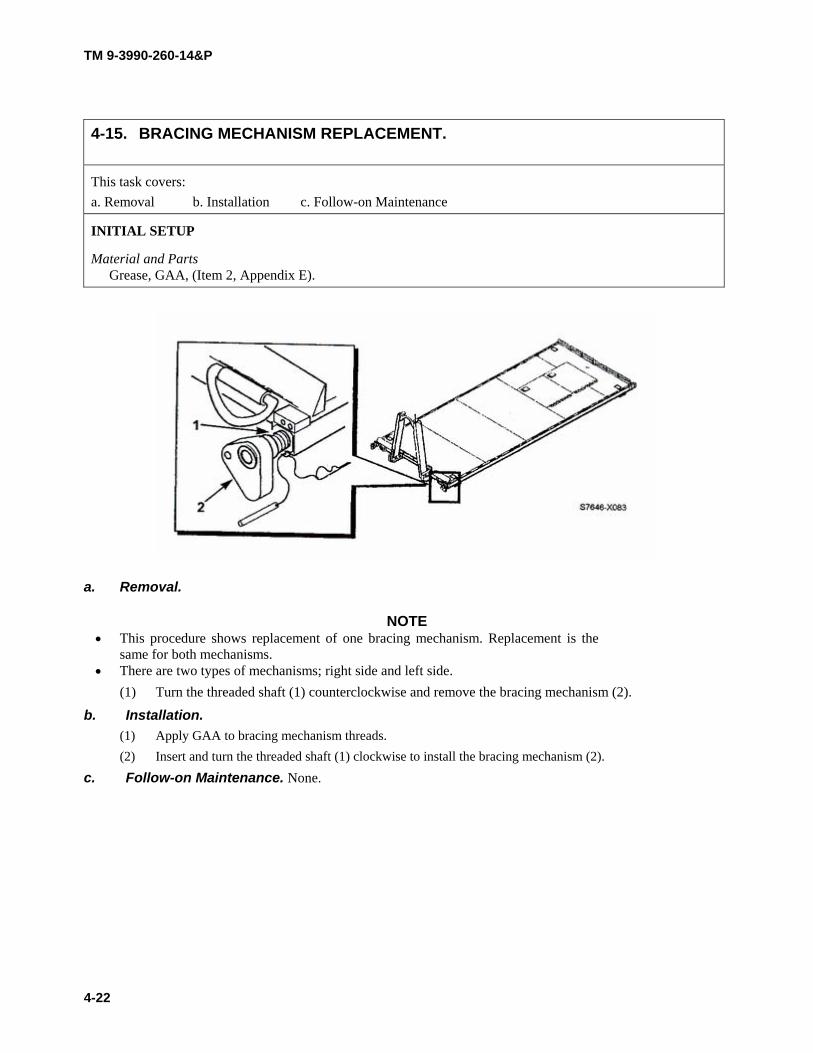
TM 9-3990-260-14&P
4-15. BRACING MECHANISM REPLACEMENT. This task covers: a. Removal b. Installation c. Follow-on Maintenance
INITIAL SETUP
Material and Parts Grease, GAA, (Item 2, Appendix E).
a. Removal.
NOTE • This procedure shows replacement of one bracing mechanism. Replacement is the
same for both mechanisms. • There are two types of mechanisms; right side and left side.
(1) Turn the threaded shaft (1) counterclockwise and remove the bracing mechanism (2).
b. Installation. (1) Apply GAA to bracing mechanism threads. (2) Insert and turn the threaded shaft (1) clockwise to install the bracing mechanism (2).
c. Follow-on Maintenance. None.
4-22

TM 9-3990-260-14&P
4-16. STOWAGE BOX DOOR MAINTENANCE.
This task covers:
a. Removal b. Installation c. Repair d. Adjustment e. Follow-on Maintenance
INITIAL SETUP
Tools and Special Tools Equipment Condition Tool Kit, General Mechanic's: Automotive (Item 5, Stowage box door opened. Appendix I). Drill, Electric, Portable (Item 2, Appendix I). Material and Parts Drill Set, Twist (Item 3, Appendix I). Rivet, Stud, 18 ea. (Item 7, Table H-2, Appendix Tool Kit, Blind Rivet (Item 6, Appendix I). H).
4-23

TM 9-3990-260-14&P
NOTE Perform the following steps for each of two stowage box doors.
a. Removal. (1) Disconnect stowage box door retaining chain hook (1) from the door (2). (2) Remove ten rivets (3) and door (2) from hinge (4). (3) Remove eight rivets (5) and hinge (4) from deck.
b. Installation. (1) Install hinge (4) to deck with eight rivets (5). (2) Install door (2) to hinge (4) with ten rivets (3). (3) Connect stowage box door retaining chain hook (1) to door (2).
c. Repair.
NOTE Stowage box latches are replaced as a set.
(1) Remove nut (6), washer (7), bolt (8), and latch (9) from door (2).
(2) Remove nut (10), washers (11), bolt (12), and latch (13) from stowage box.
(3) Install bolt (12), latch (13), washers (11), and nut (10) in stowage box.
(4) Install bolt (8), latch (9), washer (7), and nut (6) on door. (5) Replace stowage box retaining chain (14) and hooks (1) by disconnecting the hooks and
removing the chain. d. Adjustment.
(1) Loosen nut (6) securing door mounted latch (9) and nut (10) securing stowage box mounted latch (13).
(2) Align door latch (9) and stowage box latch (13). Tighten nuts (6 and 10). e. Follow-on Maintenance. None.
4-24

TM 9-3990-260-14&P
Change 1 5-1
CHAPTER 5
DIRECT SUPPORT MAINTENANCE (M3 CROP)
Para Contents Page
5-1 Common Tools and Equipment . . . . . . . . . . . . . . . . . . . . . . . . . . . . . . . . . . . . . . . . . . . . . . . . . . . . . . . . . 5-1 5-2 Special Tools, TMDE and Support Equipment . . . . . . . . . . . . . . . . . . . . . . . . . . . . . . . . . . . . . . . . . . . . 5-1 5-3 Repair Parts . . . . . . . . . . . . . . . . . . . . . . . . . . . . . . . . . . . . . . . . . . . . . . . . . . . . . . . . . . . . . . . . . . . . . . . . 5-1 5-4 Service Upon Receipt . . . . . . . . . . . . . . . . . . . . . . . . . . . . . . . . . . . . . . . . . . . . . . . . . . . . . . . . . . . . . . . . 5-1 5-5 Introduction . . . . . . . . . . . . . . . . . . . . . . . . . . . . . . . . . . . . . . . . . . . . . . . . . . . . . . . . . . . . . . . . . . . . . . . . 5-2 5-6 Additional Inspection Criteria . . . . . . . . . . . . . . . . . . . . . . . . . . . . . . . . . . . . . . . . . . . . . . . . . . . . . . . . . 5-2 5-7 General Welding Maintenance . . . . . . . . . . . . . . . . . . . . . . . . . . . . . . . . . . . . . . . . . . . . . . . . . . . . . . . . . 5-5 5-8 Deck Plate Replacement . . . . . . . . . . . . . . . . . . . . . . . . . . . . . . . . . . . . . . . . . . . . . . . . . . . . . . . . . . . . . . 5-9
Section I. REPAIR PARTS, SPECIAL TOOLS, TEST, MEASUREMENTAND DIAGNOSTIC EQUIPMENT (TMDE) AND SUPPORT EQUIPMENT
For authorized common tools and equipment, refer to the Modified Table of Organization and Equipment (MTOE)applicable to your unit.
Refer to Appendix B, the Maintenance Allocation Chart (MAC) and Appendix F, Repair Parts and Special ToolsList (RPSTL), to determine special tools, TMDE and support equipment for the M3 CROP. No fabricated tools are needed.
Repair parts are listed and illustrated in the Repair Parts and Special Tools List (RPSTL), Appendix F, covering Unit andDirect Support Maintenance for the M3 CROP.
Section II. SERVICE UPON RECEIPT
Chapter 4 contains service upon receipt instructions. Specific paragraphs are referenced for additional instructions.
a. Unpacking. Refer to paragraph 4-4a.
b. Servicing. Refer to paragraph 4-4b.
5-1. COMMON TOOLS AND EQUIPMENT.
5-2. SPECIAL TOOLS, TMDE AND SUPPORT EQUIPMENT.
5-3. REPAIR PARTS.
5-4. SERVICE UPON RECEIPT.
TM 9-3990-260-14&P
5-2 Change 1
Section III. DIRECT SUPPORT MAINTENANCE PROCEDURES
This section covers Direct Support Maintenance procedures for the M3 CROP. The following are general maintenanceprocedures to keep in mind:
a. Removal and Disassembly. Do not separate bonded, press-fitted, soldered, welded or riv-eted parts unless such removal is necessary to clean, inspect or test that part separately.
b. Inspection. (1) Inspect for loose, missing or damaged parts. (2) Check for cracks, rust or pits, especially at weld points. (3) Inspect all parts to determine if they conform to the wear limits, fits and tolerances estab-
lished.
c. Lubrication. Refer to Appendix J for lubrication requirements.
d. Assembly. Refer to notes or diagrams made during disassembly to install new parts or reas-semble.
e. Installation. Pay special attention to requirements for installing cotter pins, spring pins, man-datory replacement items, and similar operations.
a. General. The M3 CROP is not an ISO compatible container used for intermodal shipping,therefore it does not require a CSC Safety Approval. However, it is used in conjunction with containers that are ISOcompatible and do require a CSC Safety Approval. This paragraph provides inspection criteria similar to thatrequired to achieve CSC Safety Approval, but is to be used instead as the basis for determining the overall service-ability of M3 CROP.
b. Recommended Inspection Sequence. Inspection should be performed on the M3 CROPwhile empty. Although any sequence of inspection is permissible, the sequence of the inspection contained herein isrecommended. A complete examination should be performed prior to acceptance. Acceptable crack length limits arespecified in Table 5-1.
(1) Markings and Data Plates. Check for appropriate markings and data plates. (2) Overall Configuration. Check for any distortion of the overall configuration great enough
to preclude proper engagement of handling/lifting equipment, mounting and securing on aPLS truck or trailer, insertion into an ISO container, or insertion into the cell of a ship. Ifalignment is in question, use a measuring tape to check dimensions in accordance withPara 1-13.
(3) Exterior Sides and Ends. Examine the M3 CROP exterior on all sides and ends for anydefects on main structural components or unacceptable damage on center or rear blockerassemblies, fixed and removable.
(4) Understructure. Position the M3 CROP on jackstands to enable safe viewing of the M3CROP understructure. Examine the corner twistlock apertures, side and end rails,crossmembers and forklift tunnels for defects.
5-5. INTRODUCTION.
5-6. ADDITIONAL INSPECTION CRITERIA.

TM 9-3990-260-14&P
Change 1 5-3
(5) A-frame Assembly. Check for any distortion of the A-frame assembly great enough to pre-clude safe movement using the PLS truck and trailer. Check for excessive wear of the frontpins and rear pins. Excessive wear of these items requires their replacement. Check bailbar for excessive wear or cracks in weldment.
(6) Deck. Check condition of deck floor for defects. Check storage boxes in deck for service-ability and availability of BII.
(7) Deck Flooring Gaps. Excessive gaps in flooring may be determined by use of a 1 inch(2.54 cm) wide by 1/16 inch (1/59 mm) thick feeler gauge. Any suitable strip of metal maybe used.
c. Suggested Tools and Equipment. (1) Straight Edge. A wire, string or other form of a straight edge is needed to determine
whether any portion of the M3 CROP protrudes past the outside surfaces of the side rails,which would interfere with M3 CROP insertion and extraction from an ISO shipping con-tainer.
(2) Measuring Tape (Ruler). A measuring tape (ruler) is required to check dimensional toler-ances.
(3) Welder’s Hammer. A welder’s hammer (NSN 5120-00-240-3096 or equivalent) is helpfulin determining the strength of welds or metal structural components.
(4) Inspection Stands. Jackstands (Item 4, Appendix I) provide a safe means for supporting theempty M3 CROP to enable proper viewing of the M3 CROP understructure. DoD person-nel should also refer to service-specific safety guidelines about “Working Under a Sus-pended Load”.
(5) Flashlight. A flashlight improves visual acuity, especially during examination of therecesses of the understructure.
(6) Chalk. Marking (circling) location of defects with chalk as they are discovered facilitatespreparation of inspection reports and helps maintenance personnel locate areas to berepaired.
d. Primary Structural Components. An M3 CROP with any major defect in any componentof its primary structure is unacceptable. For purposes of this criteria, primary (main) structural components (mem-bers) include: twistlock housings, A-frame assembly, roller assembly brackets, forklift pockets and main rails.
(1) Main Defects. A major defect includes:(a) A dent or bend in any primary structural component that prevents the CROP for load-
ing.
(b) A crack, break, cut, tear, puncture or corrosive failure in any primary structural com-ponent.
(c) A missing, cracked or broken weld at the juncture between any primary structuralcomponent.
(d) More than two splices or an improper splice of any one floor crossmember.
(e) Any damage or degradation within a component that could place any person in dan-ger during subsequent handling, stacking or transport of the M3 CROP.
(f) More than one splice or an improper splice (such as a lapped splice) in an end rail.

TM 9-3990-260-14&P
5-4 Change 1
(2) Acceptable Welding Patterns. Welding patterns conforming to the original manufacturer’sdesign are acceptable. Only abnormal welding patterns due to damage and/or improperrepair are cause for rejection. Inspection should be directed at looking for broken junc-tures or welded repairs that are not consistent with other similar welds of the M3 CROP.
(3) Acceptable Splicing. A splice is any repair of a primary structural member that replacesmaterial without complete replacement of the member. Areas repaired by straighteningand bead welding are not to be construed as splices. Gussets, backup plates or other rein-forcement (protector) plates are not to be construed as splices. An acceptable splice is aminimum of 6 inch (15 cm) long and is a butt-welded insert. If a splice would end within12 inch (30 cm) of another weld, it must be extended to that weld. An acceptable splice isflush fitting and restores the original size and cross-sectional profile of the repaired com-ponent. Backup plates installed on the backside of a splice are permissible if the backupplate extends a minimum of 6 inch (15 cm) beyond each end of the splice.
(4) A-frame Assembly. The A-frame assembly front and rear threaded pins must not be seized,twisted, broken, missing or otherwise inoperable. Any twist, dent or bend to any of the pinsthat renders the A-frame assembly inoperable is cause for rejection. The A-frame assem-bly must not be bent or twisted in such a manner that it renders the A-frame assembly inop-erable.
(5) Tiedown and Multipurpose Provision Rings. Provisions used for attachment of web strapsor other cargo restraint devices must be in working order. Tiedown bars and securing weldpoints and multipurpose provision rings that are deformed or broken are cause for rejec-tion.
(6) Cargo Deck. An M3 CROP is unacceptable if the flooring has any of the following defi-ciencies:
(a) Any protrusion above the top surface of the deck.
(b) Any loose or missing deck plates.
(c) Deck not free of debris or residue from a previous cargo.
(d) Deck or area of deck covered with hazardous or flammable liquid.
e. Damage and Repair. (1) Patch. Any repair of a deck panel that adds or replaces material without complete replace-
ment of the panel. An acceptable patch is of permanent design, of similar material and con-figuration and weather-proof. Patch is a generic term, which for the purposes of thisinspection criteria, is reserved exclusively for repairs of non-primary components such asdeck panels.
(2) Splice. Any repair of a primary (main) structural component (member) that replaces mate-rial without complete replacement of the member. Gussets, backup plates or other rein-forcement (protector) plates are not to be construed as splices. Splice is a regulatory repairterm, which for the purposes of this inspection criteria, is reserved exclusively for repairson components of the primary structure.
(3) Gusset. Reinforcement plate, usually triangular in shape, welded between adjacent compo-nents to reinforce the structure and provide added resistance to handling damage.
(4) Backup Plate. A reinforcement (doubler) plate installed on the backside of a structuralcomponent and not on the exterior of the component’s profile. The backup plate serves tostiffen and strengthen the component.
5-6. ADDITIONAL INSPECTION CRITERIA (CONT).

TM 9-3990-260-14&P
Change 1 5-5
(5) Insert. A specific type of repair in which replacement material is fitted flush with the orig-inal component and only a partial profile of the component’s cross section is replaced.
(6) Section. A specific type of repair in which replacement material is fitted flush with theoriginal component and the entire profile of the component’s cross section is replaced.
(7) Hole. A circular penetrating puncture through any part of the CROP.
(8) Pinhole. A small hole less than 1/8 inch (3.18 mm) in diameter. A pinhole typically resultsfrom a tiny skip or porosity in a weld and usually is only detected during a light leak test.
(9) Corrosive Failure. Corrosive failure (galvanic or electrolytic) is determined when the cor-roded metal can be punched by striking the area lightly with a welder’s hammer.
(10) Caulking. A sealant compound used to provide water tightness around patches in panels,around riveted seams, in holes of pop rivets, in joints between dissimilar metals, in gapsbetween floor board edges and in gaps where the floor boards adjoin the interior wall.
(11) Undercoating. Bituminous material or other waterproof coating brushed or sprayed on theentire underside of the container floor to protect all of the metal understructure againstcorrosion.
Underneath the CARC paint, the M3 CROP is completely galvanized with zinc. Zinc fumes,released by the burning of the zinc during welding repairs, are extremely toxic. Weldingpersonnel must exercise extreme caution or wear respirators when performing welding repairs.
NOTE When weldment cracks are discovered, it is recommended that they be repaired at the nextservice interval to prevent the length of the crack from increasing and to minimize repair. Thefollowing inspection procedures are to be considered as guidelines only. Any cracksdiscovered during the inspections considered more significant, especially from a safety standpoint, should be referred to the supervisor for weld repair decisions. This would include cracksidentified in any main structural areas (main frame and main rail flanges) and cracks that haveopened and could lengthen rapidly during loading/unloading operations.
a. Weldment Points. Thoroughly inspect all weldments for cracks, chips or other damage.Areas include the end structure assembly, pin blocks, main beams, center tubes, cross beams, front and end beams,ISO twistlock housings, multipurpose provision rings and mounting brackets and D-ring mounting bars. Particularattention should be paid to the difference between a crack in the coatings and a crack in a weld or parent material.Suspected cracks in welds or parent material should be confirmed by using non-destructive examination techniques(e.g. ultra sound test or Zyglow inspection). Inspect welds for acceptable crack length limits using the followingguidelines:
5-7. GENERAL WELDING MAINTENANCE.

TM 9-3990-260-14&P
5-6 Change 1
Table 5-1. Acceptable Crack Length Limits
(1) Acceptable Welding Patterns. Welding patterns conforming to the original manufacturer’sdesign are acceptable. Only abnormal welding patterns due to damage and/or improperrepair are cause for rejection. Inspection should be directed at looking for broken junc-tures or welded repairs that are not consistent with other similar welds of the M3 CROP.Preheating of parent material is required when welding the pin support plate, pin block,bracing mechanism nut, and D-ring bar. For specifics, see paragraph 5-7, d. Crop Welding.
(2) Acceptable Splicing. A splice is any repair of a primary structural member that replacesmaterial without complete replacement of the member. Areas repaired by straighteningand bead welding are not to be construed as splices. Gussets, backup plates or otherreinforcement (protector) plates are not to be construed as splices. An acceptable splice is aminimum of 6 in. (15 cm) long and is a butt-welded insert. If a splice would end within12 in. (30 cm) of another weld, it must be extended to that weld. An acceptable splice isflush fitting and restores the original size and cross-sectional profile of the repaired com-ponent. Backup plates installed on the backside of a splice are permissible if the backupplate extends a minimum of 6 in. (15 cm) beyond each end of the splice.
5-7. GENERAL WELDING MAINTENANCE (CONT).
Areas to be Inspected Acceptable Crack Length Limits
1. Pin Blocks and Center Tube Welds andParent Material
Less than 1/4 inch (6 mm)
2. Cross Beams A crack should be repaired after it has reached 3/4 inch (19 mm).The total length of cracks on a single crossmember should notexceed 2 inches (51 mm). When cracks are present on severalcrossmembers, action should be taken to repair them at the nextservice. If a crossmember is completely missing, repairs should bemade prior to use.
3. Front and Rear Beams Less than 1/4 inch (6 mm)
4. Main Beams (Note: Bends to bottom flangeand main beams are normal.)
Cracks in the parent material or welds between the main beamsand cross beams cannot exceed 3/4 inch (19 mm).
5. Twistlocks Due to the loads twistlocks can see during retrograde transportmode, any cracks in the twistlock housing should be repairedbefore reaching 3/4 inch (19 mm).
6. A-Frame A crack should be repaired before it has reached 2 inches (5 cm).The combined length of multiple cracks at any one location shouldnot exceed 4 inches (10 cm).
7. Hookbar (Welds securing the hookbar castingon the A-frame).
Cracks should be repaired prior to reaching 1 inch (2 cm) inlength. The combined length of multiple cracks at this locationshould not exceed 1-1/2 inches (4 cm).
8. Multipurpose D-Rings Due to the high loads that these fittings can see in transport mode,any crack should be repaired before reaching 1/2 inch (1 cm) inlength. The combined length of multiple cracks at any one loca-tion should not exceed 1/2 inch (1 cm). This applies to crackspresent in the adjoining structure also.
9. Decking The maximum allowable single crack in the deck seams is 6inches (15 cm) long. When multiple cracks are present, the com-bined length of the cracks cannot exceed 10 inches (25 cm).
TM 9-3990-260-14&P
Change 1 5-7
(3) End Structure Assembly. Solid welds and parent material in this area are essential to ensuresafe loading and unloading of the CROP. These welds connect the bail bar assembly to theend structure assembly tubes and the end structure assembly tubes and support beam to thepin support plates. Cracks in the parent material of the bail bar assembly or pin supportplates are not reparable and require replacement of the end structure assembly. Testing ofweld cracks should be conducted to ensure no crack has propagated into the parent mate-rial. Cracks in welds that have not propagated into the parent material should be repairedimmediately.
(4) Bail Bar. These welds will be applied to the middle of the bail bar where contact with thePLS hook has worn the bail bar more than is allowed (see Table 4-1, item 2).
(5) Twistlocks.(6) Cross Beams. These welds are located where each lateral beam is connected to a main
beam and/or side beam. (7) Main Beams. The main beams provide the major portion of the load carrying capacity of
the CROP. They provide almost 100% of the load while loaded on the truck and trailer orresting on the ground.
(8) Stowage Boxes. The only welds are those connecting the recessed latch assembly box tothe underside of the lid. These welds should be repaired when necessary to prevent thelatch assembly box from detaching from the door.
(9) A-Frame. Solid welds in the A-frame area are necessary to ensure safe loading and unload-ing of the CROP.
(10) Hookbar. These welds are located at the base of the hookbar casting on the A-frame of theM3 CROP. These welds secure the hookbar to the A-frame and are subjected to a signifi-cant portion of the total load during loading and unloading operations.
(11) MIL-STD-209 Multipurpose Rings. The large D-rings of the CROP are used for transpor-tation. They may be used to secure the CROP to a trailer or railcar.
(12) Decking.
b. Removing the CARC Paint Primer and Galvanizing Coatings Prior to WeldRepair.
NOTE There are three options to repair a weld: 1) oxyacetylene torch; 2) sandblasting, or; 3) surfacegrinding. Use one of these options to remove CARC paint, primer and galvanizing prior toweld repair.
Use a respirator when removing paint, primer and galvanizing with an oxyacetylene torch be-cause of the toxic gases.
NOTE The galvanizing must be heated to 860°F (460°C) before it will melt.
(1) Option One. Use an oxyacetylene torch and a stainless steel wire brush to remove thepaint, primer and galvanizing. (a) Using oxyacetylene torch, heat galvanizing to 860°F (460°C).
TM 9-3990-260-14&P
5-8 Change 1
NOTE Use the brush within 1.5 inches (38 mm) on both sides of repair area.
(b) Once the galvanizing starts to melt, use a stainless steel wire brush to remove paint,primer and galvanizing.
(2) Option Two. (a) Protect the area around the weld repair with masking tape (about 1 inch on each side
of the anticipated weld deposit). This will protect the other areas of the CARC finishnot being repaired.
(b) Use sandblaster to remove paint, primer and galvanizing.
(3) Option Three. Use surface grinder (hand grinder) to remove paint, primer and galvanizingwithin one inch on either side of the anticipated weld deposit.
c. Galvanized Coating Replacement. To replace the galvanized coating, use Zinc Stick(95% zinc, 5% tin with flux) that will melt at less than 750°F (398°C), followed by a primer and top coat (CARCpaint). This is recommended repair for galvanized CROPs prior to primer and CARC paint. If the spray metalizing(Zinc) method is available, it is the preferred method. The galvanizing method is in accordance with ASTM A780and the thickness will be in accordance with ASTM E376. If there are questions about the repair method OR theapplication of one of these processes, contact the American Galvanizers Association at 1-800-468-7732 or Mr.George Shaw at the U.S. Army Tank-Automotive and Armaments Command’s Materials & Coating Group, 1-800-325-2920, extension 45083.
CAUTION
Do not weld the CROP while on trailer or truck or damage to equipment may result.
d. CROP Welding. (1) Welding on the CROP must be performed off the trailer or truck. Different areas of the
CROP require different weld electrodes and preheat. Use the following guidelines to deter-mine the correct weld and/or preheat. The bail bar center wear plate should be accom-plished using 300°F (149°C) preheat and ER110S-1 with gas metal arc welding (wire feedwelder with argon and oxygen shielding gas) or E11018-M with submerged metal arcwelding (E11018-M stick electrode and arc welder). All other areas of the CROP shouldbe welded using ER70S-6 welding wire. The following applies:
Areas not listed above do not require preheat.
5-7. GENERAL WELDING MAINTENANCE (CONT).
Weld Area Wire Preheat Temperature
Bail Bar Center Wear Repair ER110S-1 E11018-M
300°F (149°C) 300°F (149°C)
Pin Support Plate to End Structure Assembly Tubes
ER70S-6 400°F (204°C)
Pin Block to Main Beams ER70S-6 200°F (93°C)
D-Ring Bar to Side Beam ER70S-6 450°F (232°C)
Bracing Mechanism Nut to Side Beam ER70S-6 300°F (149°C)

TM 9-3990-260-14&P
Change 1 5-9
(2) Painting Instructions. Refer to TB 43-0209 and TM 43-0139 for painting instructions forthe M3 CROP.
a. Tools Required.(1) Hand Hydraulic Blind Riveter Tool Kit (NSN 5180-02-201-4979, CAGE 64878, PN D-
100-MIL-2).(2) Drill.(3) Bits (to match blind rivet).(4) Center Punch.
(5) Galvanization repair in accordance with paragraph 5-7, section C “Galvanized CoatingReplacement” or Zinc-rich paint or aerosol spray (NSN 8010-00-501-5798).
(6) Blind Rivets (NSN 5320-01-215-9148, PN MGLP-R8-6, CAGE 17446).(7) C-Clamps.
b. Galvanized Deck Plate Sections. (Components available from Summa Technology, Inc.CAGE 0BJH4):
Quantity CAGE Part Number Description
1 0BJH4 12468700 Panel, Front Deck
2 0BJH4 12468701 Panel, Mid Deck
1 0BJH4 12468702 Panel, Right Side Deck
1 0BJH4 12468704 Panel, Rear Deck
1 0BJH4 12468705 Panel, Left Side Deck
c. Replacement Procedure.(1) Remove damaged diamond plate deck plate by drilling out rivets.(2) Clean areas of the CROP where the new deck will be secured and, if the galvanization has
been damaged, repair galvanization in accordance with paragraph 5-7, section C “Galva-nized Coating Replacement” or Zinc-rich paint or aerosol spray (NSN 8010-00-501-5798).
(3) Using the damaged deck plate as a guide, mark the location of the old rivet holes on thenew section of diamond plate.
(4) Measure approximately 1 inch from the old rivet hole marks along the edge of the new dia-mond plate or in line with the subassembly of the CROP (so that when the hole is drilledthrough the diamond plate, you’re also drilling through the subassembly of the CROP) andmark the location of the new rivet with a center punch. Mark the diamond plate in an areawhere the rivet is not passing through a raised portion of the diamond plate.
(5) Place and secure the new diamond plate onto the CROP and secure using clamps. Buttjoint as close as possible.
(6) Drill through diamond plate and CROP structure at the new rivet position.(7) Deburr only the top surface of the diamond plate if needed.
5-8. DECK PLATE REPLACEMENT.

TM 9-3990-260-14&P
5-10 Change 1
(8) Rivet new diamond plate to deck. Rivets are to be applied wet with primer in accordancewith MIL-P-53022 or wet with zinc paint in accordance with MIL-P-21035.
(9) Finish:(a) Zinc phosphate pretreatment in accordance with TT-C-490.
(b) Treat, prime and paint with Chemical Agent Resistant Coating in accordance withMIL-C-53072, color green 383 (chip #34094) or black (chip #37030) (depending onthe base color of the CROP).
5-8. DECK PLATE REPLACEMENT (CONT).

TM 9-3990-260-14&P
CHAPTER 6
INTRODUCTION (M3A1 CROP)
Para Contents Page 6-1 Scope ............................................................................................................................... 6-1 6-2 Corrosion Prevention and Control .................................................................................... 6-1 6-3 Equipment Configuration ................................................................................................. 6-2 6-4 Preparation for Storage or Shipment ................................................................................ 6-2 6-5 Destruction of Army Material to Prevent Enemy Use ...................................................... 6-2 6-6 Safety, Care, and Handling ............................................................................................... 6-3 6-7 Warranty Information ....................................................................................................... 6-3 6-8 Reporting Equipment Improvement Recommendations (EIRs) ....................................... 6-3 6-9 Quality Assurance/Quality Control (QA/QC) .................................................................. 6-3 6-10 List of Abbreviations ........................................................................................................ 6-3 6-11 Equipment Characteristics, Capabilities, and Features ..................................................... 6-4 6-12 Location and Description of Major Components ............................................................. 6-6 6-13 Equipment Data ................................................................................................................ 6-8 6-14 Normal Operation ............................................................................................................. 6-8
Section I. GENERAL INFORMATION
6-1. SCOPE.
This chapter provides general information, equipment description and principles of operation for the Container Roll-In/Out Platform (M3A1 CROP).
a. Type of Manual. Operation and maintenance manual, including Repair Parts and Special Tool List (RPSTL).
b. Model Number and Equipment Name. The Container Roll-In/Out Platform (CROP) part number is 3-33000, Model M3Al, NSN 3990-01-450-5671. The M3A1 CROP is manufactured by Hyundai Preci- sion America, San Diego, CA. Figure 6-1 illustrates the M3A1 CROP in various configurations.
c. Purpose of Equipment. The M3A1 CROP is a flat cargo body with a folding front A-frame assembly, designed for use with the Palletized Load System (PLS) truck and trailer. The M3Al CROP is designed to be loaded/unloaded on the PLS truck and trailer and in an ISO container using the PLS Load Handling System (LHS). The M3A1 CROP is capable of being transported by other modes of transportation through the supply dis- tribution system in a stand-alone configuration, or in an ISO container.
6-2. CORROSION PREVENTION AND CONTROL.
The M3A1 CROP has a total service life of 20 years which allows for extended periods of operation in a corrosive environment. A corrosive environment includes exposure to high humidity, salt spray, road-deicing chemicals, gravel, and atmospheric contamination. However, because M3A1 CROP is completely galvanized, no action beyond normal washing and repair of damaged areas is necessary to control corrosion. To prevent moisture accu- mulation, drain holes are provided on structural areas where necessary. Stowage boxes are provided with drains. Lubricate the M3A1 CROP according to Appendix K. Clean with high pressure water.
6-1

TM 9-3990-260-14&P
6-3. EQUIPMENT CONFIGURATION.
a. View A. M3AI CROP shown with A-frame and load restraint plates raised, cargo loaded and secured, ready to be loaded on Palletized Load System (PLS) truck or trailer, or put inside ISO shipping container.
b. View B. M3AI CROP shown empty with A-frame and load restraint plates lowered, ready to be stacked.
c. View C. M3AI CROPs shown stacked six high and locked together, ready to be placed inside International Standards Organization (ISO) shipping container.
d. View D. M3AI CROPs shown inside and braced for transport in the ISO shipping container.
Figure 6-1. M3A1 CROP
6-4. PREPARATION FOR STORAGE OR SHIPMENT.
Refer to paragraph 7-18 and paragraph 9-4 for storage or shipment instructions for the M3A1 CROP.
6-5. DESTRUCTION OF ARMY MATERIAL TO PREVENT ENEMY USE.
Refer to TM 750-244-6, Procedures for Destruction of Tank-automotive Equipment to Prevent Enemy Use (U.S. Army Tank-automotive and Armaments Command).
6-2

TM 9-3990-260-14&P
Change 1 6-3
Beware of payload movement during normal loading/unloading operations. Ensure web straps and load restraint plates arecorrectly installed. The M3A1 CROP should be loaded on truck or trailer using the Load Handling System (LHS). M3A1CROPs should be stacked using a forklift or other material handling equipment. Never walk under an M3A1 CROP whenit is being lifted, loaded or unloaded. The M3A1 CROP deck is not capable of holding a forklift. Do not drive a forklift onthe deck while loading cargo; load from the side.
For information concerning the warranty, contact the U.S. Army Tank-automotive and Armaments Command, ATTN:AMSTA-LC-CHHE, Warren, MI 48397-5000 or telephone DSN 786-6967 or Area Code (586) 574-6967.
If your M3A1 CROP needs improvement, let us know. Send us an EIR. You, the user, are the only one who can tell us whatyou don’t like about your equipment. Let us know why you don’t like the design. Put it on an SF Form 368 (Product Qual-ity Deficiency Report). Mail it to us at: U.S. Army Tank-automotive and Armaments Command, ATTN: AMSTA-TR-E-PQDR, Warren, MI 48397-5000. We will send you a reply. For those with access to the World Wide Web (www), the EIRcan be submitted through the Army Electronic Product Support (AEPS) web site. The site is https://aeps.ria.army.mil.
If there are any Quality Assurance/Quality Control problems with the M3A1 CROP, put the problem on an SF Form 368(Product Quality Deficiency Report) and mail it to us at: U.S. Army Tank-automotive and Armaments Command,ATTN: AMSTA-TR-E-PQDR, Warren, MI 48397-5000. We will send you a reply. For those with access to the WorldWide Web (www), the QDR can be submitted through the Army Electronic Product Support (AEPS) web site. The site ishttps://aeps.ria.army.mil.
The following abbreviations are used extensively throughout this manual:
AAL Additional Authorization ListBII Basic Issue Items BOI Basis of Issue CAGE Contractor and Government Entity COEI Components of End Item CROP Container Roll-In/Out PlatformIPF ISO-Compatible Palletized FlatrackISO International Standards Organization LHS Load Handling System NSN National Stock Number PLS Palletized Load System PLST Palletized Load System Trailer PMCS Preventive Maintenance Checks and Services SMR Source, Maintenance, and Recoverability TIK Trailer Interface Kit TMDE Test, Measurement, and Diagnostic Equipment U/I Unit of Issue U/M Unit of Measure
6-6. SAFETY, CARE, AND HANDLING.
6-7 WARRANTY INFORMATION.
6-8. REPORTING EQUIPMENT IMPROVEMENT RECOMMENDATIONS (EIRs).
6-9. QUALITY ASSURANCE/QUALITY CONTROL (QA/QC).
6-10. LIST OF ABBREVIATIONS.
TM 9-3990-260-14&P
6-4
Section II. EQUIPMENT DESCRIPTION
a. Equipment Characteristics. (1) The M3A1 CROP is a welded steel, galvanized, steel-floored, flat cargo body with a fold-
ing front A-frame assembly for stacking and front and rear load restraint plates. The M3A1CROP is usually loaded and unloaded by the Load Handling System (LHS) onto a PLStruck, but can also be moved by forklift or other material handling equipment capable ofhandling such loads.
(2) A fully loaded M3A1 CROP can be inserted into and extracted from an ISO containerdirectly from a PLS truck or by using a forklift. M3A1 CROP has built-in shoring devicesto secure it inside an ISO container. No additional shoring is required.
(3) M3A1 CROP has four twistlock devices on the deck which allow each stacked M3A1CROP to be secured by the M3A1 CROP directly beneath it. Up to six M3A1 CROPs canbe stacked for movement on a PLS truck or trailer. A stack of six also fits into an ISO con-tainer. The two front and three rear load restraint plates must be repositioned to the storedposition prior to stacking for an M3A1 CROP upon which another is to be stacked.
(4) Although M3A1 CROP twistlocks function similar to ISO twistlocks, M3A1 CROP twist-locks are not positioned for use as ISO securing mechanisms due to the smaller footprint ofthe M3A1 CROP when compared to an IPF Flatrack, or regular ISO compatible piece ofequipment.
(5) M3A1 CROPs can be shipped on railcars, on PLS trucks and trailers, on flatbed trucks, andin ISO containers.
(6) Each M3A1 CROP is provided with fourteen (14) web straps to allow transport of cargo.
b. Capabilities. (1) The M3A1 CROP can be loaded to and from the ground, a loading dock, an ISO container,
or PLS trailer using the PLS truck-mounted LHS. The M3A1 CROP will accommodatepayloads of 32,250 lbs (14,629 kg) when loaded in an ISO container or on a PLS truck ortrailer.
(2) The M3A1 CROP is capable of being transported on C-130, C-141, C-5 and C-17 aircraftwhile secured to a 463L pallet train, while loaded to 36,250 lbs (16,443 kg) maximum grossweight.
(3) The M3A1 CROP is capable of being sling lifted by a CH-47D helicopter, utilizing a dualpoint lift, at a gross weight of 25,000 lbs (11,340 kg), by use of MIL-STD-209, Class 3Multipurpose D-rings.
(4) Six empty M3A1 CROPs, five with the A-frame assembly folded down, can be stackedtogether and loaded in an ISO container, on the PLS trailer, and on the PLS truck using theLHS.
(5) M3A1 CROP can be moved by a forklift with forks that are a minimum of 68 in. (173 cm)in length.
6-11. EQUIPMENT CHARACTERISTICS, CAPABILITIES, AND FEATURES.

TM 9-3990-260-14&P
c. Features. (1) A welded, fully galvanized, steel frame and deck with a hinged A-frame assembly with two
removable and three retractable load restraint plates. Capable of being stacked vertically and secured by the CROP directly beneath.
(2) Three enclosed, lockable stowage boxes in the rear deck area. (3) Hinged A-frame assembly that lays flat on the deck for stacking. (4) Side tiedown O-rings (19 per side) to secure payloads. (5) Four multipurpose provision rings, MIL-STD-209, Class 3, 72,500 lbs (32,915 kg) to permit
sling lifting by helicopter and tiedown while loaded to 36,250 lbs (16,443 kg) maximum gross weight, on rail cars and trailers. The multipurpose provision rings also accommodate tiedown of vehicles.
(6) Forklift pockets to allow movement of loaded and unloaded M3A1 CROPs. (7) Container transport locks to secure M3A1 CROP inside an ISO container. (8) Rollers at the rear of the M3Al CROP. (9) Twistlocks at each comer of the M3A1 CROP for stacking. (10) Pins for securing A-frame assembly in upright position and lowering of A-frame assembly to
horizontal position. Pins are stowed in stowage boxes on the PLS truck. (11) Tools for raising and lowering A-frame. Tools are stowed in stowage boxes on the PLS
truck.
6-5

TM 9-3990-260-14&P
6-12. LOCATION AND DESCRIPTION OF MAJOR COMPONENTS.
a. A-frame Assembly and Bail Bar. The bail bar (1) on the A-frame assembly (2) of the M3A1
CROP is used as a lifting point for the M3Al CROP. The bail bar (1) couples with the LHS hook arm to lift and pull the M3A1 CROP onto the PLS truck. The entire A-frame assembly (2) can be lowered onto the M3A1 CROP deck to prepare the M3A1 CROP for stacking. When folded, the A-frame assembly (2) fits inside the rails (3) of the M3A1 CROP above it, thus allowing them to be stacked vertically.
b. Rails. The rails (3), located on the bottom of the M3Al CROP, have locking plates (7) on each rail which mate with dinlocks on the PLS truck and trailer to secure the M3A1 CROP for road operations.
c. A-frame Assembly Hinge. Two tapered, threaded, front pins (4) with hex nut, flat washer, lock washer, and two straight, threaded, rear pins (5) (hidden from view) with hex nuts, flat washer and lock washers are provided as an integral part of the A-frame assembly (2). The pins (4 and 5) are used to secure the A-frame assem- bly (2) in the upright position for normal use and allow the A-frame assembly (2) to be folded in the horizontal position for stacking.
6-6

TM 9-3990-260-14&P
d. Container Transport Locks. The locks (6) are used to brace the M3Al CROP inside an ISO container and are located at the two front comers. No further shoring is required to secure the M3A1 CROP inside an ISO container. The locks engage the vertical shoring slot inside the door of the container.
e. Twistlocks. Twistlocks (7) are located at each comer and allow six empty M3Al CROPs to be stacked and locked together. Each CROP is secured by the twistlocks (7) of the CROP directly beneath it.
f. Stowage Boxes. Three large, lockable stowage boxes (8) are located in the deck toward the rear of the M3A1 CROP. The lids on the stowage boxes (8) are of the same material as the deck.
g. Rollers. Rollers (9) are located at the bottom rear of the M3A1 CROP. Rollers (9) are used for loading/unloading M3A1 CROP onto the trailer, and to roll into and out of an ISO container. Rollers (9) can be replaced if damaged.
h. Tiedown Rings. A total of 38 10,000 lbs (4,563 kg) capacity tiedown rings (10) are provided (19 on each side) to secure payloads.
i. MIL-STD-209, Class 3 Multipurpose Rings. Four 72,500 lbs (32,915 kg) capacity multipur- pose provisioning rings (11) are provided (two on each end) for sling lifting and securing on railcars or flatbed trucks.
CAUTION
Use load restraint plates in upright position when carrying cargo on deck of CROP. j. Load Restraint Plates. The M3A1 CROP has six load restraint plates. The left- and right-front
restraints (12) are removable and can be stowed on the deck. The center restraint (13) is welded in place. The three rear restraints (14) are hinged and must be lowered to the stowed position to allow M3A1 CROPs to be stacked.
k. Rail Transport Pins. The CROP is equipped with four rail transport pin holes in each rail, three for use on the PLS trucks, and one hole for use on the PLS trailer. During preparation for rail transport, the CROP should be secured to the truck and/or trailer with these pins.
6-7

TM 9-3990-260-14&P
6-13. EQUIPMENT DATA.
Table 6-1 contains the equipment data that applies to the M3A1 CROP.
Table 6-1. Equipment Data
Item Specification
Width: 91.50 in. (232.41 cm) Height: (Ground to Deck)
9.97 in. (25.32 cm)
(Ground to top of A-frame Assembly bail bar when laid flat on M3Al CROP deck)
17.22 in. (43.74 cm)
(Ground to top of A-frame Assembly when in raised position, not to top of marker spring)
62.90 in. (159.77 cm)
(Ground to top of A-frame Assembly when in raised position, top of marker spring)
71.50 in. (181.61 cm)
Overall Length: 233.36 in. (592.73 cm)
Deck Length (between cargo restraints): 217.00 in. (551.18 cm)
Weight: 4,000 lbs (1,814 kg)
Section III. PRINCIPLES OF OPERATION
6-14. NORMAL OPERATION.
The M3Al CROP is equipped with an A-frame assembly capable of being pinned in the upright position for nor- mal operation and placed horizontally for stacking. All components are permanently attached to the M3A1 CROP with the exception of BII, load restraint plates, A-frame assembly, twistlocks, rollers, and container transport locks. Refer to TM 9-2320-364-10 for PLS loading/unloading procedures.
BII are stored in the stowage boxes located in the cargo deck.
When stacking, all but one load restraint plate must be secured in its stowed position. At the front of the cargo deck, the center load restraint is welded in the upright position. On the left and right, a load restraint plate is lifted from its mounting slots, laid flat on the cargo deck and secured with a 3/4” bolt. At the rear of the cargo deck, three load restraint plates can pivot downward flush with the deck surface when locking pins are removed. The A-frame remains upward for the bottom M3Al. For all others stacked on top, the A-frame is lowered horizontally. Twist- locks on each M3Al hold the stack together.
6-8

TM 9-3990-260-14&P
CHAPTER 7
OPERATING INSTRUCTIONS (M3A1 CROP)
Para Contents Page 7-1 Operator's PMCS Procedures ............................................................................................. 7-1 7-2 PMCS Warnings and Cautions ........................................................................................... 7-1 7-3 Explanation of PMCS Table Entries .................................................................................. 7-2 7-4 Routing Diagram ................................................................................................................ 7-2 7-5 Interval Groupings ............................................................................................................. 7-2 7-6 M3A1 CROP Lubrication Instructions ............................................................................... 7-2 7-7 Shortened Intervals ............................................................................................................. 7-2 7-8 Assembly and Preparation for Use ..................................................................................... 7-10 7-9 Unlock and Lock Twistlocks .............................................................................................. 7-10 7-10 A-Frame Assembly Raising and Lowering Procedures. .................................................... 7-10 7-11 Front Load Restraint Plates Raising and Lowering Procedures ......................................... 7-14 7 -12 Nuclear, Biological, and Chemical (NBC) Decontamination Procedures .......................... 7 -15 7-13 Loading Single M3Al CROP on PLS Truck or Trailer ...................................................... 7-15 7-14 Stacking/Loading and Unstacking/Unloading M3A1 CROP On PLS Truck, Stacking/Loading ............................................................................................................... 7-15 7-14 Stacking/Loading and Unstacking/Unloading M3A1 CROP On PLS Truck, Unstacking/Unloading ........................................................................................................ 7-20 7-15 Stacking/Loading and Unstacking/Unloading M3Al CROP on PLS Trailer ..................... 7-23 7-16 Loading/Unloading ISO Container With M3A1 CROP From PLS Truck, Loading ......... 7-24 7-16 Loading/Unloading ISO Container With M3A1 CROP From PLS Truck, Unloading ...... 7-29 7-17 Loading/Unloading ISO Container With M3Al CROP Using Forklift, Loading ............... 7-31 7-17 Loading/Unloading ISO Container With M3Al CROP Using Forklift, Unloading ........... 7-35 7-18 Preparation for Storage or Shipment .................................................................................. 7-37 7-19 Decals and Instruction Plates ............................................................................................. 7-39
Section I. OPERATOR'S PREVENTIVE MAINTENANCE CHECKS AND SERVICES (PMCS)
7-1. OPERATOR'S PMCS PROCEDURES.
Table 7-1 (PMCS Table) has been provided so you can keep your equipment in good operating condition and ready for its primary mission.
7-2. PMCS WARNINGS AND CAUTIONS.
Always observe the Warnings and Cautions appearing in your PMCS Table. Warnings and Cautions appear before applicable procedures. You must observe these Warnings and Cautions to prevent serious injury to yourself and others, or to prevent your equipment from being damaged.
7-1

TM 9-3990-260-14&P
7-3. EXPLANATION OF PMCS TABLE ENTRIES.
a. Item Number Column. Item numbers appear in the order checks and services must be done for the Interval listed. Numbers in this column are also for reference. When completing DA Form 2404 (Equipment Inspection and Maintenance Worksheet), include the number for the check/service indicating a fault.
b. Interval Column. This column tells you when you must perform the procedure in the procedure column.
Perform the "Before" CHECKS prior to using your equipment. Perform the "During" CHECKS during the time you are using your equipment. Perform the "After" CHECKS after you have used the equipment.
c. Location Check/Service Column. This column provides the location and the item to be checked or serviced.
d. Procedure Column. This column gives the procedure you must perform to check or service the item listed in the Check/Service column to know if the equipment is ready or available for its intended mission or for operation. You must perform the procedure at the time stated in the interval column.
e. Not Fully Mission Capable If: Column. Information in this column tells you what faults will keep your equipment from being capable of performing its primary mission. If you experience check and service proce-dures that show faults listed in this column, do not operate the equipment. Follow standard operating procedures for maintaining the M3Al CROP or reporting equipment failure.
f. Other Table Entries. Be sure to observe all special information and notes that appear in your table.
7-4. ROUTING DIAGRAM. Figure 7-1 is a routing diagram showing the path to use around the M3A1 CROP during PMCS. Perform PMCS in the same order and following the same route each time. 7-5. INTERVAL GROUPINGS.
Operator PMCS intervals for the M3Al CROP are as indicated in Table 7-1 and paragraph 7-3b above. 7-6. M3A1 CROP LUBRICATION INSTRUCTIONS.
Lubrication of the M3Al CROP is the responsibility of the operator/crew. Refer to Appendix K for lubrication instructions pertaining to the M3Al CROP. 7-7. SHORTENED INTERVALS.
Lubrication intervals are based on normal operation. Change the interval if lubricants are contaminated or if oper- ating the CROP under adverse operating conditions. Lubrication intervals for CROP at Appendix K are based on time.
7-2

TM 9-3990-260-14&P
Figure 7-1. PMCS Walk-Around Table 7-1. Operator's Preventive Maintenance Checks and Services
Item No.
Interval
Location Item to Check/Service
Procedure
Not Fully Mission Capable If:
1 Before A-frame Assembly Pins
Ensure front pins (1) are installed and secured in A-frame assembly.
Parts are missing or damaged.
7-3

TM 9-3990-260-14&P
Table 7-1. Operator's Preventive Maintenance Checks and Services - Continued Item No.
Interval
Location Item to Check/Service
Procedure
Not Fully Mission Capable If:
The following applies to inserting an M3A1 CROP into an ISO container. Use of the M3A1 CROP on a PLS truck or trailer is not affected.
2 Before Wear Plates a. Ensure wear plates (2) are fas- tened to side or end rails and are not torn or loose.
a. Wear plate is severely torn, chipped, damaged or missing. Normal scraped con- dition is permitted.
b. Ensure no part of a wear plate (2) is protruding in such manner that it could catch on the door frame of an ISO container.
b. A wear plate is torn or otherwise protruding from the side of the M3A1 CROP in such a manner that it could interfere with ISO container insertion procedures or dam- age the ISO container.
3 Before Web Straps a. Before loading a CROP, check quantity and condition/operability of web straps (3). Fourteen web straps are located in the stowage boxes.
a. Enough cargo web straps are missing, damaged, bro- ken, bent, frayed, or inopera- ble that there is not sufficient quantity for mission.
b. Ensure ratchet assembly (4) oper- ates properly.
b. Ratchet is inoperable.
c. Ensure hooks (5) are available and not broken, bent, or cracked.
c. Hook is broken, bent or cracked.
7-4

TM 9-3990-260-14&P
Table 7-1. Operator's Preventive Maintenance Checks and Services - Continued
Item No.
Interval
Location Item to Check/Service
Procedure
Not Fully Mission Capable If:
4 During Web Straps
Shortly after starting a mission and after driving over rough terrain, stop driving, get out and ensure cargo web straps (3) are not damaged and the cargo has not shifted. Tighten web straps if required.
Cargo web straps are damaged and allow cargo to move. Insufficient web straps to complete the mission.
5 After Load Restraint Plates
a. Visually inspect center load restraint (6) for damage. b. Visually inspect left and right load restraint plates (7) to ensure they are straight and free of bends and damage that would prevent installation of cargo.
c. Visually inspect rear load restraint plate (8) for damage to hinges.
d. Visually inspect rear load restraint plates (8) to ensure they are straight and free of bends and damage that would prevent installation of cargo.
Load restraints are missing or cannot be used properly.
7-5

TM 9-3990-260-14&P
Table 7-1. Operator's Preventive Maintenance Checks and Services – Continued Item No.
Interval
Location Item to Check/Service
Procedure
Not Fully Mission Capable If:
6 After Twistlocks a. Push handle (9) up and rotate completely from stowed position to locked position.
Twistlock will not rotate, cannot be pushed up to the locked position from the stowed position, or is damaged so it cannot be properly engaged or disengaged.
b. Inspect twistlock (10) for damage or corrosion.
c. Rotate and pull down handle (9) to stowed position.
d. Visually inspect for corrosion, dirt, and damage. Clean as required.
e. Ensure set screw is tight.
7-6

TM 9-3990-260-14&P
Table 7-1. Operator's Preventive Maintenance Checks and Services - Continued
Item No.
Interval
Location Item to Check/Service
Procedure
Not Fully Mission Capable If:
7 After Rollers a. Ensure each roller (11) will rotate.
Either roller is so worn, split, or defaced that proper loading to trailer or into ISO container is not possible.
b. Ensure each roller is not defaced or so out of round it will not roll prop- erly.
8 After Bail Bar Check bail bar (12) for cracks or bent bar.
Bail bar has cracks or is bent.
Bail bar may have metal slivers or sharp edges. Wear gloves if handling or injury to personnel could result.
7-7

TM 9-3990-260-14&P
Table 7-1. Operator's Preventive Maintenance Checks and Services - Continued Item No.
Interval
Location Item to Check/Service
Procedure
Not Fully Mission Capable If:
9 After Web Straps Check quantity and condition of web straps (3). Fourteen web straps are located in the stowage boxes.
Web straps are missing or damaged. Mission load cannot be properly secured.
10 After Stowage Boxes Ensure doors (13) or fasteners (14) are not damaged.
Door cannot be closed.
11 After Multipurpose Provision Rings
Ensure all multipurpose provision rings (15) are serviceable and not damaged or distorted to the point that they can no longer be used for their primary purpose.
One multipurpose provision ring is nonoperational.
12 After Tiedown D-rings
Ensure tiedowns D-rings (16) are serviceable.
Enough tiedown O-rings are missing or damaged so load cannot be properly secured.
7-8

TM 9-3990-260-14&P
Table 7-1. Operator's Preventive Maintenance Checks and Services - Continued Item No.
Interval
Location Item to Check/Service
Procedure
Not Fully Mission Capable If:
13 After Cargo Deck Check top surface of cargo deck (17) for damage.
Cargo deck is damaged enough to be unsuitable for loading.
14 After Container Transport Locks
Ensure latch (18) and shims (19) are in fully retracted position.
15 After Container Transport Locks
a. Ensure latch (18) moves freely in bracket (20).
Either container transport lock is unserviceable.
b. Ensure locking pin (21) is not bent or damaged.
c. Ensure cables (22) of locking pin and latch are intact.
d. Ensure four shims (19) are intact. 16 After Tools Ensure tools are in PLS truck stowage
box (refer to TM 9-2320-364-10).
17 After Bumper Ensure both bumpers (23) are available and serviceable.
Either bumper is missing or damaged beyond use.
18 After A-Frame Assembly Pins (Rear Pins)
Ensure castle nuts on rear pins are serviceable.
7-9

TM 9-3990-260-14&P
Section II. OPERATION UNDER USUAL CONDITIONS
7-8. ASSEMBLY AND PREPARATION FOR USE.
a. Unpacking. Refer to Para 9-4, Unpacking and Packing, for unpacking instructions.
b. Assembly and Installation. The M3Al CROP is delivered fully assembled.
7-9. UNLOCK AND LOCK TWISTLOCKS.
Procedures for unlocking and locking twistlocks are covered in stacking and unstacking procedures, paragraph 7- 14. The twistlocks are used to secure stacked M3A1 CROPs. They are not ISO compatible.
7-10. A-FRAME ASSEMBLY RAISING AND LOWERING PROCEDURES.
a. Raising the A-frame Assembly.
7-10
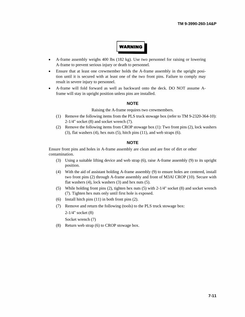
TM 9-3990-260-14&P
• A-frame assembly weighs 400 lbs (182 kg). Use two personnel for raising or lowering A-frame to prevent serious injury or death to personnel.
• Ensure that at least one crewmember holds the A-frame assembly in the upright posi- tion until it is secured with at least one of the two front pins. Failure to comply may result in severe injury to personnel.
• A-frame will fold forward as well as backward onto the deck. DO NOT assume A- frame will stay in upright position unless pins are installed.
NOTE Raising the A-frame requires two crewmembers.
(1) Remove the following items from the PLS truck stowage box (refer to TM 9-2320-364-10): 2-1/4" socket (8) and socket wrench (7).
(2) Remove the following items from CROP stowage box (1): Two front pins (2), lock washers (3), flat washers (4), hex nuts (5), hitch pins (11), and web straps (6).
NOTE Ensure front pins and holes in A-frame assembly are clean and are free of dirt or other contamination.
(3) Using a suitable lifting device and web strap (6), raise A-frame assembly (9) to its upright position.
(4) With the aid of assistant holding A-frame assembly (9) to ensure holes are centered, install two front pins (2) through A-frame assembly and front of M3Al CROP (10). Secure with flat washers (4), lock washers (3) and hex nuts (5).
(5) While holding front pins (2), tighten hex nuts (5) with 2-1/4" socket (8) and socket wrench (7). Tighten hex nuts only until first hole is exposed.
(6) Install hitch pins (11) in both front pins (2). (7) Remove and return the following (tools) to the PLS truck stowage box:
2-1/4" socket (8) Socket wrench (7)
(8) Return web strap (6) to CROP stowage box.
7-11

TM 9-3990-260-14&P
7-10. A-FRAME ASSEMBLY RAISING AND LOWERING PROCEDURES (CONT).
b. Lowering the A-frame Assembly:
A-frame assembly weighs 400 lbs (182 kg). Use two personnel for raising or lowering A-frame to prevent serious injury or death to personnel.
NOTE Lowering the A-frame requires two crewmembers.
(1) Remove the following items from the PLS truck stowage box (refer to TM 9-2320-364-10): socket wrench (7) 2-1/4" socket (8) Hammer (12)
7-12

TM 9-3990-260-14&P
(2) Remove web straps (6) from CROP stowage box (1). (3) Using a suitable lifting device and web strap (6), hold A-frame assembly (9) in its upright
position. (4) Remove hitch pins (11) from both front pins (2).
(5) While holding front pins (2), loosen hex nuts (5) with 2-1/4" socket (8) and socket wrench (7).
(6) With the aid of assistant holding A-frame assembly (9), remove two hex nuts (5), lock wash-ers (3), flat washers (4) and front pins (2) from front of M3A1 CROP (10) and A-frame assembly (9).
(7) Place A-frame assembly (9) in the lowered position. (8) To ensure that nuts, washers and hitch pins do not get lost or damaged, reassemble them on
the front pins before returning them to the stowage box. (9) Remove and return the following items to PLS truck stowage box (refer to TM 9-2320-364-
10): Socket wrench (7) 2-1/4” socket (8) Hammer (12)
(10) Return the following items to CROP stowage box (1): Front Pins (2) Washers (4) Lock Washers (3) Hex Nuts (5) Web Straps (6)
7-13

TM 9-3990-260-14&P
7-11. FRONT LOAD RESTRAINT PLATES RAISING AND LOWERING PROCEDURES.
a. Raising the Front Load Restraint Plates.
NOTE Both front load restraint plates are raised the same way.
(1) Remove special bolt (1) holding front load restraint plate (2) to deck (3) using 3/4" open end wrench.
(2) Lift front load restraint plate (2) from deck (3) and position plate into two slots (4) of deck with flat side of plate facing center of deck. Capture load restraint plate (2) with bolt in lug (5).
b. Lowering the Front Load Restraint Plates.
NOTE Both front load restraint plates are lowered the same way.
(1) Loosen special bolt (1), lift front load restraint plate (2) from two slots (4) of deck (3) and position plate to deck with flat side of plate facing downward.
(2) Install special bolt (1) thru front load restraint plate (2) and into deck (3). Tighten special bolt with 3/4" open end wrench.
7-14

TM 9-3990-260-14&P
7-12. NUCLEAR, BIOLOGICAL, AND CHEMICAL (NBC) DECONTAMINATION PROCEDURES.
Refer to FM 3-11.5, Chemical, Biological, and Radiological Decontamination, for CBR instructions.
7-13. LOADING SINGLE M3A1 CROP ON PLS TRUCK OR TRAILER.
For loading and transporting a single loaded or unloaded M3A1 CROP on truck or trailer, the A-frame assembly must be secured in the raised position. Refer to TM 9-2320-364-10 for procedures to load and unload the M3A1 CROP to truck or trailer using the Load Handling System (LHS).
7-14. STACKING/LOADING M3A1 CROP ON PLS TRUCK.
a. Stacking/Loading.
• M3A1 CROPs must be empty when stacked. Attempting to stack loaded M3A1 CROPs could cause serious injury or death to personnel.
• Always lift a stack of M3A1 CROPs by connecting to the bottom M3A1 CROP, either by overhead MHE or forklift. Failure to comply may result in severe injury to person- nel or damage to equipment.
CAUTION
• Front load restraint plates must be stowed and rear load restraint plates must be low- ered prior to stacking.
• Stacked CROPs cannot be properly inserted into ISO container until rear MIL-STD- 209 multi-purpose provision rings are in stowed (horizontal) position and rear restraint plates are lowered.
• Ensure all tiedown rings are in their lowest position prior to stacking.
NOTE
• Six M3A1 CROPs loaded on PLS truck is maximum if legal height requirement must be met.
• M3A1 CROPs may be stacked either on the ground or on the truck.
• The LHS can load PLS truck or trailer with M3A1 CROP stacked with 5 more M3A1 CROPs.
• There must be at least one empty M3A1 CROP loaded on truck using the PLS.
• Two people are required for stacking/loading M3A1 CROPs.
7-15

TM 9-3990-260-14&P
7-14. STACKING/LOADING M3A1 CROP ON PLS TRUCK (CONT).
(1) For the M3A1 CROP upon which another is being stacked (bottom M3Al CROP), push up
and turn handle (1) on all four comer twistlocks (2) to the UNLOCKED position. The twist- locks raised to the UNLOCKED position act as guides for M3A1 CROP being stacked (top M3Al CROP).
(2) Remove three web straps (3) from stowage boxes (4) located in the deck of the last M3A1 CROP to be stacked (the one which will end up on top).
• Ensure web straps are wrapped a minimum of three times around ratchet of web strap.
Failure to comply may result in web strap being released and M3A1 CROP may fall, causing severe injury or death to personnel.
• One M3A1 CROP weighs 4,000 lbs (1,814 kg). Six M3A1 CROPs weigh 24,000 lbs (10,909 kg). Ensure all personnel stand clear when M3A1 CROP is being moved. Failure to comply may result in severe injury or death to personnel.
• Always lift a stack of M3A1 CROPs by connecting to the bottom M3A1 CROP, either by overhead MHE or forklift. Failure to comply may result in severe injury to person- nel or damage to equipment.
(3) On each M3Al CROP to be stacked, ensure A-frame assembly (5) is in the lowered position.
7-16

TM 9-3990-260-14&P
(4) Attach one web strap (3) from left to right, to two front tiedown O-rings (6), third from the end.
(5) Attach a second web strap (3) from left to right, to two rear tiedown O-rings (6), third from the end.
(6) Attach a third web strap (3) to tiedown O-ring (7) at rear of M3A1 CROP for use as a hand- hold.
Ensure pads on web straps are positioned in lifting clevis of lifting device. Failure to com- ply may result in breakage of web straps causing severe injury or death to personnel. (7) Attach two web straps (3) to hook of lifting device (8).
7-17

TM 9-3990-260-14&P
7-14. STACKING/LOADING M3A1 CROP ON PLS TRUCK (CONT).
M3A1 CROP weighs 4,000 lbs (1,814 kg). Ensure all personnel stand clear when M3A1 CROP is being moved. Failure to comply may result in severe injury or death to personnel.
Ensure lifting device is positioned directly over center prior to lifting M3A1 CROP off ground. Failure to comply may result in uneven lifting. Damage to equipment may result.
CAUTION
(8) With the aid of an assistant holding web strap (3), raise lifting device until M3A1 CROP clears ground. Ensure M3A1 CROP is level.
NOTE If M3A1 CROP is not being raised level, perform Steps (9) through (11). If M3A1 CROP is level, go on to Step (12).
(9) If M3A1 CROP is not level, lower M3A1 CROP to ground. (10) Shorten or lengthen two web straps (3) as required. (11) Repeat Steps (8) through (11) until M3A1 CROP is level when raised.
CAUTION
Ensure M3A1 CROP twistlocks are free of snow, dirt, and debris prior to lowering M3A1 CROP being stacked or proper locking will not occur.
NOTE The twistlocks in the UNLOCKED position will guide the M3A1 CROP to the correct position to lock the twistlocks of the bottom M3A1 CROP.
(12) Using the lifting device (8) and assistant holding web strap (3), position and lower M3A1 CROP onto M3A1 CROP with A-frame assembly in raised position or onto M3A1 CROP on top of stack.
7-18

TM 9-3990-260-14&P
(13) Turn handle (1) on all four twistlocks (2) (bottom M3A1 CROP) until stacked M3Al CROP
(top M3Al CROP) is locked in place. (14) Remove lifting device (8) and three web straps (3) from four tiedown D-rings (6) and rear
tiedown D-ring (7). (15) Repeat steps (3) through (14) for additional M3Al CROPs being stacked. Each is locked in
place using twistlocks of the M3Al CROP below it. (16) For the last M3Al CROP stacked (the top CROP), secure A-frame assembly (5) in lowered
position by attaching one web strap (3) from first D-ring across to the sixth D-ring on other side. Tighten web strap.
(17) If stack of M3A1 CROPs is to be loaded into ISO container, stow two remaining web straps (3) into stowage box (4).
7-19

TM 9-3990-260-14&P
7-14. STACKING/LOADING M3A1 CROP ON PLS TRUCK (CONT).
CAUTION
Ensure LHS hook is hooked only in M3Al CROP with A-frame assembly in the raised position, located on bottom of stack. Failure to comply will result in improper loading and damage will occur to equipment.
(18) Load stack on PLS truck or trailer. Refer to TM 9-2320-364-10 for procedures to load and unload the M3Al CROP to truck or trailer using the Load Handling System (LHS).
b. Unstacking/Unloading. (1) Using the LHS, remove stack of M3A1 CROPs from truck. Refer to TM 9-2320-364-10 for
procedures to unload the M3A1 CROP from truck or trailer using the Load Handling System (LHS).
(2) Remove all web straps (3) from stack of M3Al CROPs.
Ensure web straps are wrapped a minimum of three times around ratchet of web strap. Failure to comply may result in web strap being released and M3A1 CROP may fall, caus- ing severe injury or death to personnel.
(3) Attach one web strap (3) from left to right, to two front tiedown D-rings (6), third from the end.
(4) Attach a second web strap (3) from left to right, to two rear tiedown D-rings (6), third from the end.
(5) Attach third web strap (3) to tiedown D-ring (7) at rear of the M3A1 at top of stack, for use as a handhold.
7-20

TM 9-3990-260-14&P
CAUTION
Personnel are cautioned that failure to release all four twistlocks prior to lifting top M3A1 CROP could result in damage to equipment.
(6) On the M3A1 CROP beneath M3A1 CROP to be lifted, turn handle (1) on all four twistlocks (2) to UNLOCK position. This releases the M3A1 CROP directly above to be unstacked and lifted.
• Ensure pads on web straps are positioned in lifting clevis of lifting device. Failure to
comply may result in breakage of web straps causing severe injury or death to person- nel.
• M3A1 CROP weighs 4,000 lbs (1,814 kg). Ensure all personnel stand clear when M3A1 CROP is being moved. Failure to comply may result in severe injury or death to personnel.
7-21

TM 9-3990-260-14&P
7-14. STACKING/LOADING M3A1 CROP ON PLS TRUCK (CONT).
CAUTION
Ensure lifting device is positioned directly over center prior to lifting M3A1 CROP, Fail- ure to comply may result in uneven lifting. Damage to equipment may result.
(7) Position lifting device (8) directly over center of M3A1 CROP to be lifted.
(8) Attach two web straps (3) to lifting device (8).
(9) Slowly lift M3A1 CROP, closely observing that it is disengaged from M3A1 CROP beneath. With the aid of an assistant using web strap (3) on rear D-ring (7), lift and guide M3A1 CROP to position on ground.
(10) Remove two web straps (3) from lifting device (8).
(11) Remove three web straps (3) from four D-rings (6) and rear D-ring (7).
(12) Repeat Steps (3) through (11) for additional M3A1 CROPs being removed from stack.
(13) Stow all web straps (3) in stowage box (4) of the M3A1 CROP from which the straps were originally removed.
7-22

TM 9-3990-260-14&P
7-15. STACKING/LOADING M3A1 CROP ON PLS TRAILER.
Stacking/Loading and Unstacking/Unloading.
NOTE • Procedures for stacking and unstacking CROPs on PLS truck or trailer are the same.
• Refer to TM 9-2320-364-10 for procedures to load and unload CROP to truck or trailer using the Load Handling System (LHS).
• Once CROPs are stacked on PLS truck, they are off-loaded onto PLS trailer using the following procedure in the use of the Trailer Interface Kit (TIK).
a. Remove left- and right-side parts of the Trailer Interface Kit (TIK) from their storage location on the PLST.
b. Inspect for any damage to TIK parts and where they are to be positioned on the trailer for any dam- age or dirt that might prevent proper seating and use of the TIK.
• There are both left-side and right-side parts of the TIK. In order for them to operate
properly, they must be engaged on the proper side.
• To ensure proper engagement and operation of the TIK, the following installation instructions must be followed.
c. Secure right-side part of the TIK to right-rear comer of trailer frame bed as follows: (1) Position TIK part with sloped portion (1) facing forward on the trailer frame bed, toward the
trailer tongue. (2) With squared back portion (2) of the TIK part flush against and contacting the rear-most por-
tion of the trailer frame, engage hook portion (3) over inboard trailer guide rail. d. Repeat step c for left-side part of TIK. e. Ensure both right-side and left-side TIK parts are securely installed. f. Follow instructions in TM 9-2320-364-10 to off-load CROPs from PLS truck.
7-23
TM 9-3990-260-14&P
7-16. LOADING/UNLOADING ISO CONTAINER WITH M3A1 CROP FROM PLS TRUCK.
NOTE The use of ramps, as depicted in this task, is optional.
a. Loading.
• One M3A1 CROP weighs 4,000 lbs (1,814 kg). Six M3A1 CROPS weighs 24,000 lbs
(10,909 kg). Ensure all personnel stand clear of M3A1 CROP when M3A1 CROP is being moved. Failure to comply may result in severe injury or death to personnel.
• Always lift a stack of M3A1 CROPs by connecting lifting device to the bottom M3A1 CROP. Failure to comply may result in severe injury or damage to equipment.
• Attempting to load stack of M3A1 CROPs or a loaded M3A1 CROP in ISO container requires extreme care to prevent damage to equipment. Clearance between the ceiling of the ISO container and top of the load and inside walls of the ISO container and each side of M3A1 CROP is designed to be close, requiring at least one ground guide to assist during the difficult insertion procedure.
CAUTION
• Most commercial ISO containers are 8 foot, 6 inches high. Some containers are only 8 feet high, especially those used by U.S. Marine Corps. Ensure the container being used is 8 feet, 6 inches, as determined by container data plate on door, See Appendix M.
• Stacked CROPs cannot be properly inserted into ISO container until rear MIL-STD- 209 multi-purpose provision rings are in stowed (horizontal) position and rear restraint plates are lowered.
NOTE
• A stack of six M3A1 CROPs is maximum that can be loaded into an ISO container.
• A "loaded M3Al CROP" can be either a stack of M3A1 CROPs or an M3A1 CROP loaded with other cargo.
7-24
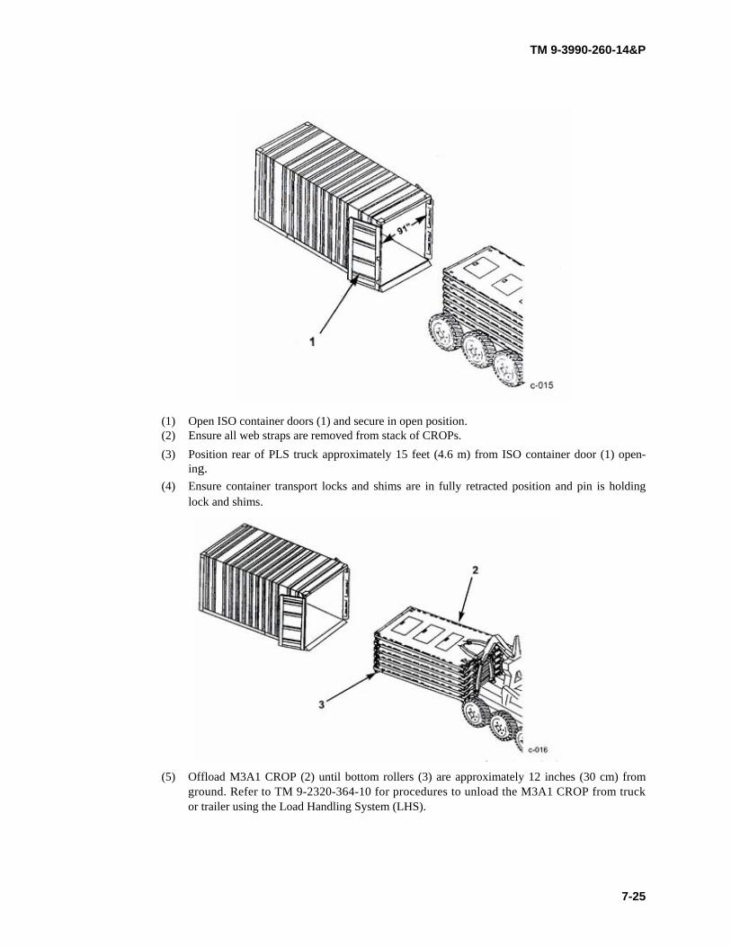
TM 9-3990-260-14&P
(1) Open ISO container doors (1) and secure in open position. (2) Ensure all web straps are removed from stack of CROPs. (3) Position rear of PLS truck approximately 15 feet (4.6 m) from ISO container door (1) open-
ing. (4) Ensure container transport locks and shims are in fully retracted position and pin is holding
lock and shims.
(5) Offload M3A1 CROP (2) until bottom rollers (3) are approximately 12 inches (30 cm) from ground. Refer to TM 9-2320-364-10 for procedures to unload the M3A1 CROP from truck or trailer using the Load Handling System (LHS).
7-25

TM 9-3990-260-14&P
7-16. LOADING/UNLOADING ISO CONTAINER WITH M3A1 CROP FROM PLS TRUCK (CONT).
Do not stand between the M3Al CROP and the ISO container. Ensure all personnel stand clear of M3Al CROP when M3Al CROP is being moved. Failure to comply may result in severe injury or death to personnel.
CAUTION
M3A1 CROP is designed to fit into ISO containers with a door opening of 91 inches (231 cm). If a container is more than 10 years old, the door opening may not be wide enough. DO NOT attempt to force CROP into containers with door openings less than 91 inches (231 cm).
(6) Using the ground guide to assist, drive PLS backward and carefully insert rear of M3A1 CROP (2) approximately 24 inches (61 cm) into door opening of ISO container (4). Several attempts to insert the M3A1 CROP (2) may be required because the ISO container (4) door opening is only slightly wider than the M3Al CROP (2).
(7) Using extreme caution to ensure rollers (3) remain inside ISO container (4), continue off- loading stack of M3Al CROPs (2), allowing PLS truck to be pushed forward or by alter- nately driving forward several feet, stopping, and offloading more of the M3A1 CROP (2) into the ISO container (4), then repeating the procedure.
NOTE If M3Al CROP load is too tall to insert the load into the ISO container according to steps (6) and (7) above, perform steps (8) through (10) below.
(8) Position ISO container loading ramps (5) (Appendix 0, paragraph 0-2) on the ground, in front of and against the ISO container door opening so the M3A1 CROP rollers (3) can roll up the ramp (5) and onto the ISO container (4).
(9) Offload M3Al CROP (2) until rollers (3) are grounded in front of the ISO container loading ramps (5) and the front of the M3A1 CROP (2) is approximately 12 inches (30 cm) from ground.
(10) With assistant providing ground guidance, use PLS truck to push M3A1 CROP (2) up load- ing ramps (5) and into ISO container (4) until M3Al CROP rollers (3) are inside the ISO container (4) approximately 24 inches (61 cm).
7-26

TM 9-3990-260-14&P
CAUTION
Closely observe stack of M3A1 CROPs during this part of offloading to ensure it does not come in contact with top of ISO container door opening or inside walls of ISO container. Failure to exercise extreme caution during insertion may result in damage to ISO container or M3A1 CROP.
(11) With the ground guide watching closely, drive the PLS truck backward very slowly and push the M3A1 CROP (2) into the ISO container (4). At the ground guide's direction, use the rear wheel steering capability of the PLS truck to guide the M3A1 CROP (2) into the ISO con- tainer (4). If the M3A1 CROP (2) appears to be out of alignment inside the ISO container (4), stop backward movement and pull M3Al CROP (2) forward several feet using the rear wheel steering capability of the PLS truck to realign the M3A1 CROP (2). After the M3A1 CROP (2) has been properly realigned inside the ISO container (4), again drive the PLS truck backward very slowly and push the M3A1 CROP (2) into the ISO container (4), using the rear wheel steering capability of the PLS truck to guide the M3A1 CROP (2).
(12) Lower the PLS lift-hook (6) until the CROP (2) is resting on the ISO container (4) floor. (13) Remove the hook arm extension assembly (7) from the PLS BII storage. Attach the hook arm
extension (7) to the PLS lift-hook (6). Check that the hook arm extension is securely attached to the lift-hook.
7-27
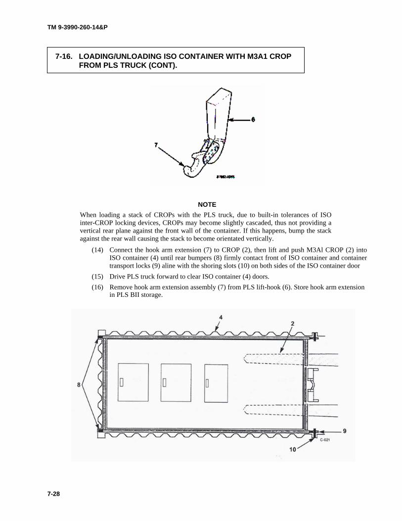
TM 9-3990-260-14&P
7-16. LOADING/UNLOADING ISO CONTAINER WITH M3A1 CROP FROM PLS TRUCK (CONT).
NOTE When loading a stack of CROPs with the PLS truck, due to built-in tolerances of ISO inter-CROP locking devices, CROPs may become slightly cascaded, thus not providing a vertical rear plane against the front wall of the container. If this happens, bump the stack against the rear wall causing the stack to become orientated vertically.
(14) Connect the hook arm extension (7) to CROP (2), then lift and push M3Al CROP (2) into ISO container (4) until rear bumpers (8) firmly contact front of ISO container and container transport locks (9) aline with the shoring slots (10) on both sides of the ISO container door
(15) Drive PLS truck forward to clear ISO container (4) doors. (16) Remove hook arm extension assembly (7) from PLS lift-hook (6). Store hook arm extension
in PLS BII storage.
7-28
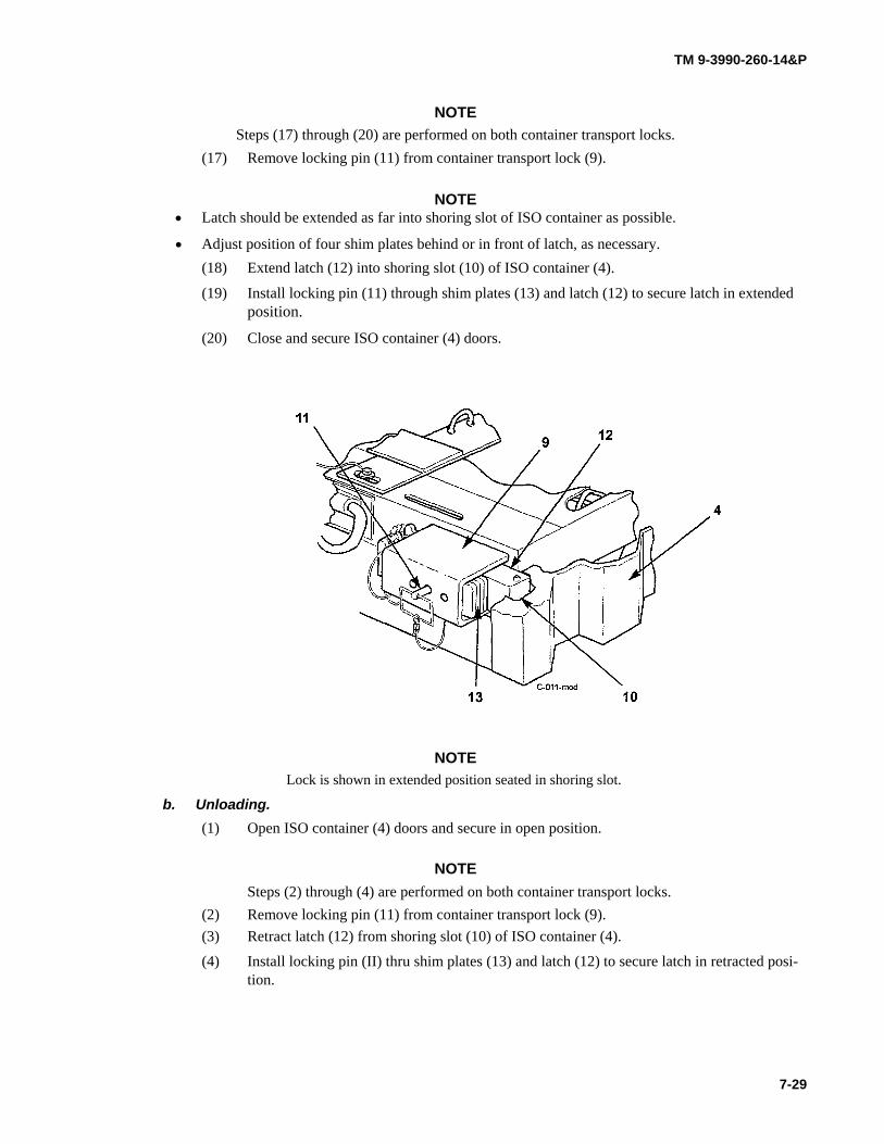
TM 9-3990-260-14&P
NOTE Steps (17) through (20) are performed on both container transport locks.
(17) Remove locking pin (11) from container transport lock (9).
NOTE • Latch should be extended as far into shoring slot of ISO container as possible.
• Adjust position of four shim plates behind or in front of latch, as necessary. (18) Extend latch (12) into shoring slot (10) of ISO container (4).
(19) Install locking pin (11) through shim plates (13) and latch (12) to secure latch in extended position.
(20) Close and secure ISO container (4) doors.
NOTE Lock is shown in extended position seated in shoring slot.
b. Unloading. (1) Open ISO container (4) doors and secure in open position.
NOTE
Steps (2) through (4) are performed on both container transport locks. (2) Remove locking pin (11) from container transport lock (9). (3) Retract latch (12) from shoring slot (10) of ISO container (4).
(4) Install locking pin (II) thru shim plates (13) and latch (12) to secure latch in retracted posi- tion.
7-29

TM 9-3990-260-14&P
7-16. LOADING/UNLOADING ISO CONTAINER WITH M3A1 CROP FROM PLS TRUCK (CONT).
(5) Position ISO container loading ramps (5) (Appendix G, paragraph G-2) on the ground, in
front of and against door opening.
Do not stand between M3A1 CROPs and ISO container. Ensure all personnel stand clear of M3A1 CROP when M3A1 CROP is being moved. Failure to comply may result in severe injury to personnel.
CAUTION
Exercise extreme caution to prevent contact between the PLS truck hook arm and top of ISO container door opening. Failure to comply can result in damage to ISO container door frame and/or door latches.
7-30

TM 9-3990-260-14&P
(6) Position PLS truck in front of ISO container (4), extend the PLS loading arm, and engage the PLS hook arm to the bail bar on M3Al CROP (2).
(7) Drive PLS truck forward, pulling the M3Al CROP (2) out of the ISO container (4) and down the loading ramps (5) (Appendix G, paragraph G-2) until the rollers are grounded.
(8) Load M3Al CROP onto PLS truck. Refer to TM 9-2320-364-10 for procedures to load the
M3Al CROP onto truck or trailer using the Load Handling System (LHS).
NOTE Ensure the top of the load or web strap ratchet assemblies do not contact the top of the ISO container door as the M3Al CROP is being removed from the ISO container. It may be necessary to stop loading, drive the PLS truck backward, and resume loading the M3Al CROP, alternately.
a. Loading.
• Forklift must be capable of lifting gross weight (18 tons) of loaded M3Al CROP plus
have side-shift capability. Failure to comply may result in damage to equipment or severe injury or death to personnel. Do not drive a forklift on the M3Al CROP deck; doing so will exceed point load capability of the deck.
• One M3Al CROP weighs 4,000 lbs (1,814 kg). Six M3Al CROPs weigh 24,000 lbs (10,909 kg). Gross weight of a fully loaded M3Al CROP is 36,250 lbs (16,443 kg). Ensure all personnel stand clear when M3Al CROP is being moved. Failure to com- ply may result in severe injury or death to personnel.
• Attempting to load an M3A1 CROP in ISO container requires extreme care to prevent damage to equipment. Clearance between the inside of ISO container and each side of M3Al CROP is designed to be close.
7-17. LOADING/UNLOADING ISO CONTAINER WITH M3A1 CROP USING FORKLIFT.
7-31

TM 9-3990-260-14&P
7-17. LOADING/UNLOADING ISO CONTAINER WITH M3A1 CROP USING FORKLIFT (CONT).
• Always lift a stack of M3A1 CROPs by connecting to the bottom M3A1 CROP. Fail- ure to comply may result in severe injury to personnel or damage to equipment.
• Forklifts are required to have forks a minimum of 68 in. (173 cm) in length. Failure to comply may result in severe injury to personnel or damage to equipment.
NOTE A stack of six M3A1 CROPs is the maximum that can be loaded into an ISO container.
(1) Open ISO container (1) doors and secure in open position. (2) With the aid of a guide, position M3A1 CROP (2) directly in front of and to within 6 inches
(15 cm) of ISO container door opening. Using forklift (3) lateral (side-shift) movement, move the M3A1 CROP laterally until the rollers are inside the ISO container. Lower the M3A1 CROP, resting the rollers on the front of the ISO container and the front of the M3A1 CROP on the ground.
(3) With the aid of a guide, ensure the M3A1 CROP is carefully aligned for insertion into the ISO container (1).
7-32

TM 9-3990-260-14&P
• Ensure forklift tines are horizontal or pointed slightly downward to ensure they do not
contact crossmembers or the underside of the deck when the tines are being inserted under the M3A1 CROP or when the M3A1 CROP is being lifted from the front. Prior to lifting, ensure the tines are in full contact with the front beam and are not contacting crossmembers. Failure to comply may result in damage to equipment.
• Ensure forklift tines are positioned to the outside of the M3A1 CROP main beams, between the main beams and the large multipurpose provision rings.
• Exercise extreme caution to ensure the M3A1 CROP is properly aligned to be inserted into the ISO container. The M3A1 CROP is designed with less than ½ inch clearance on either side between the M3A1 CROP and ISO container door frame and corrugated side walls. Failure to comply may result in damage to equipment.
NOTE
Aluminum wear plates (rub strips) along each side of CROP are designed to protect corru- gated steel wall of container from edge of CROP deck and to assist in sliding CROP into container. These rub strips will become scraped with use.
NOTE
Use forklift lateral movement during insertion to steer M3A1 CROP into container, exer- cising caution to ensure M3A1 CROP remains laterally centered to prevent damage to sides of container.
7-33

TM 9-3990-260-14&P
7-17. LOADING/UNLOADING ISO CONTAINER WITH M3A1 CROP
USING FORKLIFT (CONT).
(4) Using forklift (3), lift front of M3Al CROP (2) and push it into the ISO container (1) until the
rear bumpers (4) fully contact and seat against the inside front of the ISO container. CROP is "seated" when container transport lock (7) can be installed into shoring slot (9) on both sides of ISO container.
(5) If M3A1 CROPs (2) cannot be pushed into ISO container (1) far enough to engage ISO con- tainer (1) rear wall because forklift (3) will not allow it to go far enough inside the ISO con- tainer or the forklift otherwise contacts the container, lower the M3A1 CROPs and reposition forklift approximately 12 inches (30 cm) aft. Insert a 4" x 4" or larger board (5) between the M3A1 CROP and forklift, resting on the forklift tines, to provide sufficient range for the forklift to push it into the ISO container until the rear bumpers (4) fully contact the inside front of the ISO container.
(6) Using forklift lateral movement, ensure M3A1 CROP (2) is centered laterally in door frame of container.
NOTE
Steps (7) through (9) are performed on both container transport locks. (7) Remove locking pin (6) from container transport lock (7).
NOTE
• Latch should be extended as far into shoring slot of ISO container as possible. • Adjust position of four shim plates behind or in front of latch, as necessary, to com-
pletely fill up shoring slot. (8) Extend latch (8) into shoring slot (9) of ISO container (1). (9) Install locking pin (6) thru shim plates (10) and latch (8) to secure latch in extended position. (10) Locking pin (6) may be in position A, B or C, as indicated on instruction decal, depending
on depth of shoring slot in container. Shim plates (10) may be in front or rear of latch (8) depending on internal length of container.
(11) Close and secure ISO container (1) doors.
7-34

TM 9-3990-260-14&P
b. Unloading.
• Forklift must be capable of lifting gross weight of loaded M3A1 CROP (36,250 lbs).
Failure to use proper forklift comply may result in damage to equipment or severe injury or death to personnel.
• One empty M3A1 CROP weighs 4,000 lbs (1,814 kg). Six M3A1 stacked CROPs weigh 24,000 lbs (10,909 kg). Gross weight of a fully loaded M3A1 CROP is 36,250 lbs (16,443 kg). Ensure all personnel stand clear when M3A1 CROP is being moved. Failure to comply may result in severe injury or death to personnel.
• Attempting to load an M3A1 CROP in ISO container requires extreme care to prevent damage to equipment. Clearance between the inside of ISO container and each side of M3A1 CROP is unusually close. Wear plates (rub strips) are designed to slide along walls of container.
• Always lift a stack of M3A1 CROPs by connecting to the bottom M3A1 CROP. Fail- ure to comply may result in severe injury to personnel or damage to equipment.
• Forklifts are required to have forks a minimum of 68 in. (173 cm) in length. Failure to comply may result in severe injury to personnel or damage to equipment.
NOTE
A stack of six M3A1 CROPs is the maximum that can be loaded into an ISO container.
7-35

TM 9-3990-260-14&P
7-17. LOADING/UNLOADING ISO CONTAINER WITH M3A1 CROP USING FORKLIFT (CONT).
(1) Open ISO container (1) doors and secure in open position.
NOTE Steps (2) through (4) are performed on both container transport locks.
(2) Remove locking pin (6) from container transport lock (7). (3) Retract latch (8) and shims (10) from shoring slot (9) of ISO container (1).
(4) Install locking pin (6) thru shim plates (10) and latch (8) to secure latch in fully retracted position.
• Ensure forklift tines are horizontal or pointed slightly downward to ensure they do not
contact crossmembers or the underside of the deck when the tines are being inserted under the M3A1 CROP or when the M3A1 CROP is being lifted from the front. Prior to lifting, ensure the tines are in full contact with the front beam and are not contacting crossmembers. Failure to comply may result in damage to equipment.
• Ensure forklift tines are positioned to the outside of the M3A1 CROP main beams, between the main beams and the multipurpose provision rings. Do not attempt to lift front of M3A1 CROP with forklift tines on the inside of main beams. Failure to com- ply may result in damage to equipment.
(5) Lift front of M3A1 CROP (2) 3-5 inches (8-13 cm), or as much as the load will allow up to 18 inches (46 cm).
7-36
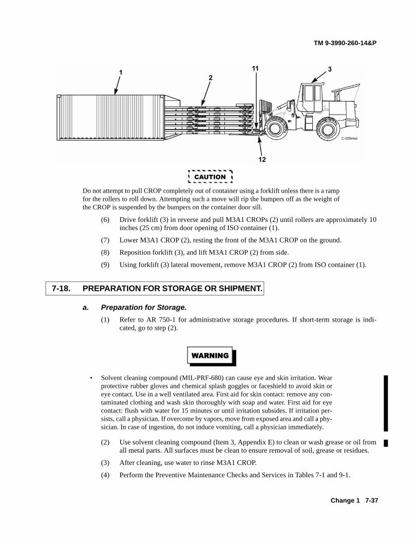
TM 9-3990-260-14&P
Change 1 7-37
CAUTION
Do not attempt to pull CROP completely out of container using a forklift unless there is a rampfor the rollers to roll down. Attempting such a move will rip the bumpers off as the weight ofthe CROP is suspended by the bumpers on the container door sill.
(6) Drive forklift (3) in reverse and pull M3A1 CROPs (2) until rollers are approximately 10inches (25 cm) from door opening of ISO container (1).
(7) Lower M3A1 CROP (2), resting the front of the M3A1 CROP on the ground.
(8) Reposition forklift (3), and lift M3A1 CROP (2) from side.
(9) Using forklift (3) lateral movement, remove M3A1 CROP (2) from ISO container (1).
a. Preparation for Storage. (1) Refer to AR 750-1 for administrative storage procedures. If short-term storage is indi-
cated, go to step (2).
• Solvent cleaning compound (MIL-PRF-680) can cause eye and skin irritation. Wearprotective rubber gloves and chemical splash goggles or faceshield to avoid skin oreye contact. Use in a well ventilated area. First aid for skin contact: remove any con-taminated clothing and wash skin thoroughly with soap and water. First aid for eyecontact: flush with water for 15 minutes or until irritation subsides. If irritation per-sists, call a physician. If overcome by vapors, move from exposed area and call a phy-sician. In case of ingestion, do not induce vomiting, call a physician immediately.
(2) Use solvent cleaning compound (Item 3, Appendix E) to clean or wash grease or oil fromall metal parts. All surfaces must be clean to ensure removal of soil, grease or residues.
(3) After cleaning, use water to rinse M3A1 CROP.
(4) Perform the Preventive Maintenance Checks and Services in Tables 7-1 and 9-1.
7-18. PREPARATION FOR STORAGE OR SHIPMENT.

TM 9-3990-260-14&P
7-38
(5) Refer to Appendix K and perform all lubrication procedures.
(6) Schedule the next PMCS on DD Form 314, Preventive Maintenance Schedule and Record.
(7) Report all deficiencies on DA Form 2407 if the deficiencies appear to involve unsatisfactorydesign.
(8) Spot paint all surfaces as necessary (TB 43-0209).
b. Preparation for Shipment. (1) Complete storage instructions according to paragraph 7-17a. Preparation for Storage, above.
(2) Refer to AR 746-80 for Marking of Supplies for Shipment.
(3) Refer to AR 725-5 and prepare all shipping documents to accompany M3A1 CROP.
(4) Refer to TM 9-2300-281-35, Standards of Overseas Shipment or Domestic Issue of SpecialPurpose Vehicles, if M3A1 CROP is to be shipped overseas.
7-18. PREPARATION FOR STORAGE OR SHIPMENT (CONT).

TM 9-3990-260-14&P
7-19. DECALS AND INSTRUCTION PLATES.
a. Stencils. The word "LIFT" is stenciled at four places on M3AI CROP, two on each side. b. Identification and Shipping Data Plates. Refer to Figure 7-2 for location and description of
plates. c. Container Transport Pin Instruction Decal. Refer to Figure 7-2 for location and
description of decal.
Figure 7-2. Location and Description of Decals and Instruction Plates
Item Description
1 Forklift fork insertion lift points, side.
2 Identification Plate.
3 Shipping Plate.
4 Container Deadbolt Instruction Decal.
7-39/(7-40 blank)

TM 9-3990-260-14&P
CHAPTER 8
OPERATOR MAINTENANCE INSTRUCTIONS (M3A1 CROP)
Para Contents Page
8-1 Troubleshooting Introduction ........................................................................................... 8-1 8-2 Troubleshooting Symptoms ............................................................................................. 8-1 8-3 Maintenance Introduction ................................................................................................ 8-2
Section I. TROUBLESHOOTING PROCEDURES
8-1. TROUBLESHOOTING INTRODUCTION.
This section contains step-by-step procedures for identifying, locating and isolating equipment malfunctions.
8-2. TROUBLESHOOTING SYMPTOMS.
Refer to Table 8-1 for a list of Troubleshooting Symptoms. Table 8-2 lists the most common troubleshooting proce- dures found during operation or maintenance of the M3A1 CROP. Tests or inspections and corrective actions should be performed in the order listed. If a malfunction is not listed or is not corrected by listed corrective actions, notify the supervisor.
Table 8-1. Operator Troubleshooting Symptom Index
Troubleshooting Procedure Page
1. Container transport locks won't engage shoring slots in ISO shipping container ................. 8-2
8-1

TM 9-3990-260-14&P
8-2. TROUBLESHOOTING SYMPTOMS (CONT).
Table 8-2. Operator Troubleshooting Procedures
MALFUNCTION TEST OR INSPECTIONS CORRECTIVE ACTION
1. CONTAINER TRANSPORT LOCKS WON’T ENGAGE SHORING SLOTS IN ISO SHIPPING CONTAINER.
Are shim plates out of position?
• Remove locking pin and adjust position of shim plates in front of or behind latch. Replace locking pin. (See paragraph 7-16 or 7-17).
Is locking pin missing or damaged?
• If locking pin is missing or damaged, contact unit maintenance.
Section II. MAINTENANCE INSTRUCTIONS
8-3. MAINTENANCE INTRODUCTION.
Maintenance procedures for the replacement or repair of the A-frame, twistlocks, rollers, container transport locks, wear plates, load restraint plates, door holders, bumpers and stowage box doors are covered in Chapter 9.
8-2

TM 9-3990-260-14&P
9-1
CHAPTER 9
UNIT MAINTENANCE INSTRUCTIONS(M3A1 CROP)
Para Contents Page
9-1 Common Tools and Equipment . . . . . . . . . . . . . . . . . . . . . . . . . . . . . . . . . . . . . . . . . . . . . . . . . 9-19-2 Special Tools, TMDE, and Support Equipment . . . . . . . . . . . . . . . . . . . . . . . . . . . . . . . . . . . . . 9-19-3 Repair Parts . . . . . . . . . . . . . . . . . . . . . . . . . . . . . . . . . . . . . . . . . . . . . . . . . . . . . . . . . . . . . . . . 9-19-4 Unpacking and Packing . . . . . . . . . . . . . . . . . . . . . . . . . . . . . . . . . . . . . . . . . . . . . . . . . . . . . . . 9-29-5 Lubrication . . . . . . . . . . . . . . . . . . . . . . . . . . . . . . . . . . . . . . . . . . . . . . . . . . . . . . . . . . . . . . . . 9-39-6 Hand Receipt . . . . . . . . . . . . . . . . . . . . . . . . . . . . . . . . . . . . . . . . . . . . . . . . . . . . . . . . . . . . . . . 9-39-7 Introduction (PMCS) . . . . . . . . . . . . . . . . . . . . . . . . . . . . . . . . . . . . . . . . . . . . . . . . . . . . . . . . . 9-49-8 Unit PMCS Procedures . . . . . . . . . . . . . . . . . . . . . . . . . . . . . . . . . . . . . . . . . . . . . . . . . . . . . . . 9-49-9 PMCS Table Explanation . . . . . . . . . . . . . . . . . . . . . . . . . . . . . . . . . . . . . . . . . . . . . . . . . . . . . . 9-59-10 Introduction (Unit Maintenance Procedures) . . . . . . . . . . . . . . . . . . . . . . . . . . . . . . . . . . . . . . . 9-119-11 General Maintenance Instructions . . . . . . . . . . . . . . . . . . . . . . . . . . . . . . . . . . . . . . . . . . . . . . . 9-119-12 A-Frame Assembly Replacement . . . . . . . . . . . . . . . . . . . . . . . . . . . . . . . . . . . . . . . . . . . . . . . . 9-139-13 Twistlock Replacement . . . . . . . . . . . . . . . . . . . . . . . . . . . . . . . . . . . . . . . . . . . . . . . . . . . . . . . 9-169-14 Roller Replacement . . . . . . . . . . . . . . . . . . . . . . . . . . . . . . . . . . . . . . . . . . . . . . . . . . . . . . . . . . 9-189-15 Container Transport Lock Replacement . . . . . . . . . . . . . . . . . . . . . . . . . . . . . . . . . . . . . . . . . . . 9-209-16 Wear Plate Replacement . . . . . . . . . . . . . . . . . . . . . . . . . . . . . . . . . . . . . . . . . . . . . . . . . . . . . . . 9-229-17 Load Restraint Plates (Rear) Replacement . . . . . . . . . . . . . . . . . . . . . . . . . . . . . . . . . . . . . . . . 9-249-18 Door Holder Replacement . . . . . . . . . . . . . . . . . . . . . . . . . . . . . . . . . . . . . . . . . . . . . . . . . . . . . 9-259-19 Bumper Replacement . . . . . . . . . . . . . . . . . . . . . . . . . . . . . . . . . . . . . . . . . . . . . . . . . . . . . . . . . 9-269-20 Stowage Box Door Replacement . . . . . . . . . . . . . . . . . . . . . . . . . . . . . . . . . . . . . . . . . . . . . . . 9-27
Section I. REPAIR PARTS, SPECIAL TOOLS, TEST, MEASUREMENTAND DIAGNOSTIC EQUIPMENT (TMDE) AND SUPPORT EQUIPMENT
For authorized common tools and equipment, refer to the Modified Table of Organization and Equipment (MTOE)applicable to your unit.
Refer to Appendix B, the Maintenance Allocation Chart (MAC) and Appendix F, Repair Parts and Special ToolsList (RPSTL), to determine special tools, TMDE and support equipment for the M3A1 CROP. No fabricated toolsare needed.
Repair parts are listed and illustrated in the Repair Parts and Special Tools List (RPSTL), Appendix F, covering Unitand Direct Support Maintenance for the M3A1 CROP.
9-1. COMMON TOOLS AND EQUIPMENT.
9-2. SPECIAL TOOLS, TMDE AND SUPPORT EQUIPMENT.
9-3. REPAIR PARTS.

TM 9-3990-260-14&P
9-2 Change 1
Section II. SERVICE UPON RECEIPT
This paragraph provides information required to ensure the M3A1 CROP is adequately inspected, serviced and oper-ationally tested before it is subjected to normal everyday use. The procedures cover unpacking, deprocessing andpacking.
a. Unpacking. (1) Remove any metal strapping, plywood, tapes, seals, wrapping or any other shipping and
protective items.
• Solvent cleaning compound (MIL-PRF-680) can cause eye and skin irritation. Wearprotective rubber gloves and chemical splash goggles or faceshield to avoid skin oreye contact. Use in a well ventilated area. First aid for skin contact: remove any con-taminated clothing and wash skin thoroughly with soap and water. First aid for eyecontact: flush with water for 15 minutes or until irritation subsides. If irritation per-sists, call a physician. If overcome by vapors, move from exposed area and call a phy-sician. In case of ingestion, do not induce vomiting, call a physician immediately.
(2) If any parts other than those shown in the lubrication order are coated with lubricating oilor grease, remove with solvent cleaning compound (Item 3, Appendix E).
(3) Inspect M3A1 CROP for damage incurred during shipping. If M3A1 CROP has been dam-aged, report the damage.
(4) Check the equipment against the packing slip to ensure shipment is complete. Report alldiscrepancies in accordance with DA PAM 750-8.
b. Servicing. (1) Perform the Preventive Maintenance Checks and Services (PMCS) in Tables 7-1 and 9-1.
(2) Schedule the next PMCS on DD Form 314, Preventive Maintenance Schedule and Record.
(3) Report all deficiencies on DA Form 2407 if the deficiencies appear to involve unsatisfac-tory design.
c. Packing. Preservation and other protective measures taken in the preparation of material andaccompanying tools and equipment for shipment must be sufficient to protect the material against deterioration andphysical damage during shipment.
9-4. UNPACKING AND PACKING.

TM 9-3990-260-14&P
Change 1 9-3
• Solvent cleaning compound (MIL-PRF-680) can cause eye and skin irritation. Wearprotective rubber gloves and chemical splash goggles or faceshield to avoid skin oreye contact. Use in a well ventilated area. First aid for skin contact: remove any con-taminated clothing and wash skin thoroughly with soap and water. First aid for eyecontact: flush with water for 15 minutes or until irritation subsides. If irritation per-sists, call a physician. If overcome by vapors, move from exposed area and call a phy-sician. In case of ingestion, do not induce vomiting, call a physician immediately.
(1) Use solvent cleaning compound (Item 3, Appendix E) to clean or wash grease or oil fromall metal parts. All surfaces must be clean to ensure removal of corrosion, soil, grease orresidues.
(2) After cleaning, use water to rinse M3A1 CROP. Dry all parts thoroughly with a lint-freecloth (Item 1, Appendix E).
(3) Lubricate according to procedures in Appendix K.
(4) Spot paint all surfaces as necessary (TB 43-0209).
Refer to Appendix K for lubrication instructions pertaining to the M3A1 CROP.
Refer to Appendix C, Components of End Item (COEI) and Basic Issue Items (BII) Lists for proper inventory andcontrol procedures.
9-5. LUBRICATION.
9-6. HAND RECEIPT.

TM 9-3990-260-14&P
9-4
Section III. UNIT MAINTENANCE PREVENTIVE MAINTENANCECHECKS AND SERVICES (PMCS)
This section presents Unit Maintenance checks and services. Figure 9-1 illustrates the route to use in completingthe PMCS procedures. Table 9-1 provides PMCS procedures. Unit Maintenance should also perform OperatorPMCS (paragraph 7-1).
Figure 9-1. PMCS Walk-Around
a. Always perform your preventive maintenance in the same order, so it gets to be a habit. Once youhave some practice, you will spot anything wrong in a hurry.
b. If something looks wrong and you cannot fix it, write it down on DA Form 2404.
9-7. INTRODUCTION.
9-8. UNIT PMCS PROCEDURES.

TM 9-3990-260-14&P
Change 1 9-5
• Solvent cleaning compound (MIL-PRF-680) can cause eye and skin irritation. Wearprotective rubber gloves and chemical splash goggles or faceshield to avoid skin oreye contact. Use in a well ventilated area. First aid for skin contact: remove any con-taminated clothing and wash skin thoroughly with soap and water. First aid for eyecontact: flush with water for 15 minutes or until irritation subsides. If irritation per-sists, call a physician. If overcome by vapors, move from exposed area and call a phy-sician. In case of ingestion, do not induce vomiting, call a physician immediately.
c. Clean as you work and as needed. Dirt, grease, oil and debris may get in the way and cover up aproblem. Use solvent cleaning compound (Item 3, Appendix E) to clean M3A1 CROP where dirt, grease or oil hasaccumulated.
d. Check for missing, loose, bent or broken bolts, nuts and screws. Look for chipped paint, baremetal or rust around bolt heads. Tighten loose parts.
e. Look for loose paint, rust or gaps where parts are welded together. If you find a bad weld, report itto Direct Support Maintenance.
f. If cracks are detected, notify Direct Support Maintenance to perform further inspection.
a. Do the SEMI-ANNUAL PREVENTIVE MAINTENANCE (Table 9-1) once every six months. b. Always do the Preventive Maintenance in the same order until it gets to be a habit. Once prac-
ticed, it will be easy to spot anything wrong in a hurry. c. If anything looks wrong and is not fixed, write it on a DA Form 2404. d. When doing Preventive Maintenance, take along the tools and supplies needed to make all the
checks, including a clean cloth or two. e. The following is a breakdown of the PMCS table:
(1) “Item No.” column. Checks and services are numbered in a logical order for movingaround the M3A1 CROP. The item number column is used as a source of item numbers forthe TM Number Column on DA Form 2404, Equipment Inspection and MaintenanceWorksheet, for recording results of the PMCS.
(2) “Interval” column. This column identifies when the PMCS should be performed. (3) “Item to Check/Service” column. This column identifies the item to be checked/serviced. (4) “Procedure” column. This column contains all the information required to do the check/
inspection. (5) “Not Mission Capable If:” column. This column contains a brief statement of the condi-
tion (e.g., malfunction, shortage) that would cause the M3A1 CROP to be less than fullyready to perform its assigned mission.
9-9. PMCS TABLE EXPLANATION.

TM 9-3990-260-14&P
9-6
Table 9-1. Unit Maintenance Preventive Maintenance Checks and Services - Continued
Item No.
IntervalLocation
Item toCheck/Service
Procedure Not Fully MissionCapable If:
1 Semi-Annually
Twistlocks a. Inspect twistlocks (1) for damage or missing parts. Report damage or missing parts to supervisor.b. Using 4 mm allen wrench, ensure set-screw in twistlock handle is tight.c. Ensure no crack greater than 3/4 inch (19 mm) exists in the welds or the parent material of the twistlock housing.
a. Damage is found that will impair operation, or any part is missing.
c. Twistlock housing or parent material contains a crack greater than 3/4 inch (19 mm).
2 Semi-Annually
D-rings Inspect for deformed, cracked, or missing D-rings (2) and cross bars (3).
Enough damage is found or enough D-rings are missing so load cannot be properly secured.

TM 9-3990-260-14&P
Table 9-1. Unit Maintenance Preventive Maintenance Checks and Services - Continued Item No.
Interval
Location Item to Check/Service
Procedure
Not Fully Mission Capable If:
3 Semi- Annually
Stowage Box Doors
a. Check stowage box doors (4) for bends and dents.
b. Check that door hinge (5) and door holder (6) operate correctly and that stowage box door (4) can be secured with padlock.
a. Stowage box door is bent or will not lay flat.
b. Door hinge or door holder are damaged or stow- age box door cannot be opened or closed.
9-7

TM 9-3990-260-14&P
Table 9-1. Unit Maintenance Preventive Maintenance Checks and Services - Continued Item No.
Interval
Location Item to Check/Service
Procedure
Not Fully Mission Capable If:
6 Semi- Annually
Rollers
a. Inspect exterior of roller (7) to ensure it is not broken or so defaced that it does roll properly.
b. Inspect center roller next to shaft to ensure it is not worn more than 1/4 inch (6.35 mm) between bushing and roller material (if bushing is not present).
c. Ensure axle (8) is straight, with all hardware attached. d. Ensure head of shaft (toward cen- ter of CROP) has at least 1/8 inch (3.18 mm) of material.
a. Roller is broken or so defaced that it does not roll properly.
b. Center of roller exceeds wear criteria. c. Shaft is bent so roller will not roll or hardware is missing so roller can detach.
d. Head of shaft exceeds wear criteria.
5 Semi- Annually
Container Transport Locks
Check locks (9) for damaged or missing parts. Report damaged or missing parts to supervisor.
Damage is found that will impair operation or any part is missing.
9-8

TM 9-3990-260-14&P
Table 9-1. Unit Maintenance Preventive Maintenance Checks and Services - Continued Item No.
Interval
Location Item to Check/Service
Procedure
Not Fully Mission Capable If:
6 Semi- Annually
A-frame Assembly
a. Ensure two front pins (10) and rear pins (11) are not bent, galled, cracked, corroded or stripped so that they do not seat properly or they can- not be sufficiently tightened.
b. Visually inspect all welds and par- ent material for cracks
c. Ensure A-frame assembly (13) frame is not bent, preventing it from loading correctly on a PLS truck.
d. Ensure split cotter pins (14) are still thru hole in rear pins (11).
a. Front and rear pin(s) bent, cracked, corroded or stripped so they do not seat properly or cannot be suffi- ciently tightened.
b. Parent material or weld is cracked.
c. A-frame assembly is bent so the M3Al CROP can- not be loaded and properly secured on PLS truck.
d. If cotter pin is missing, tighten nut (12) and re-insert pin.
9-9

TM 9-3990-260-14&P
Table 9-1. Unit Maintenance Preventive Maintenance Checks and Services - Continued Item No.
Interval
Location Item to Check/Service
Procedure
Not Fully Mission Capable If:
7 Semi- Annually
Bail Bar Check bail bar (15) for wear. If wear at lower back side of bar is greater than 1/4 in. (6.35 mm) or greater than 1/8 in. (3.175 mm) at bottom of bar, notify supervisor.
Wear found exceeds specification.
8 Semi- Annually
M3A1 CROP Weldments
Visually inspect all weldments (16) for cracks and other damage. Report damage to supervisor.
Cracks or broken welds are found that will impair operation.
Bail bar may have metal slivers or sharp edges. Wear gloves if handling or injury to personnel could result
9-10

TM 9-3990-260-14&P
9-11
Section IV. UNIT MAINTENANCE PROCEDURES
This section presents Unit Maintenance procedures for the M3A1 CROP. These procedures may include servicing,hoisting, inspection, cleaning, removal and disassembly, inspection, assembly, and installation and any proceduresneeded for placing the M3A1 CROP or its components into service.
a. Servicing. The M3A1 CROP requires only lubrication and cleaning as service.
b. Hoisting Loaded M3A1 CROP.
An M3A1 CROP and load can weigh up to 36,250 lbs (16,443 kg). A loaded M3A1 CROPon a PLS truck or trailer must not exceed 36,250 lbs (16,443 kg). Attach suitable liftingdevice to avoid serious injury or death to personnel.
(1) For other than ordinary operation, M3A1 CROP must be lifted with a forklift or other liftingdevice. The M3A1 CROP is loaded on and off the Palletized Load System (PLS) Truck orthe PLS Trailer using the Load Handling System (LHS). Refer to TM 9-2320-364-10.
CAUTION
Do not load or unload M3A1 CROP with loose cargo or damage to equipment or cargomay result.
(2) Install web straps before lifting any load.
(3) When lifting a loaded M3A1 CROP using multipurpose provision rings located at front andrear of M3A1 CROP, use a spreader bar if necessary to avoid damage to load.
c. Inspection of Installed Parts. Perform inspection with the item in its normally installed posi-tion/condition, considering accessibility and visibility of the item being inspected. The purpose of the inspection isto determine if the item is damaged or incomplete to the extent that it should be replaced/repaired.
(1) Inspect for loose, missing or damaged parts.
(2) Inspect parts for dents, holes, worn spots, scratches, marred finish, cracks, rust and corrosion.
(3) Look for loose or chipped paint, rust or gaps where parts are welded together. If a bad weld isfound, notify your supervisor.
9-10. INTRODUCTION.
9-11. GENERAL MAINTENANCE INSTRUCTIONS.

TM 9-3990-260-14&P
9-12 Change 1
• Solvent cleaning compound (MIL-PRF-680) can cause eye and skin irritation. Wearprotective rubber gloves and chemical splash goggles or faceshield to avoid skin or eyecontact. Use in a well ventilated area. First aid for skin contact: remove any contami-nated clothing and wash skin thoroughly with soap and water. First aid for eye contact:flush with water for 15 minutes or until irritation subsides. If irritation persists, call aphysician. If overcome by vapors, move from exposed area and call a physician. Incase of ingestion, do not induce vomiting, call a physician immediately.
d. Cleaning. Remove buildup of dirt and grease by wiping with a cloth (Item 1, Appendix E). Use acloth or wire scratch brush (Item 1, Appendix I) and solvent cleaning compound (Item 3, Appendix E) to clean metalparts. Allow to dry.
e. Removal. During removal process, tag (Item 4, Appendix E) similar parts for ease of installa-tion.
f. Disassembly. During disassembly, tag (Item 4, Appendix E) similar parts for ease of installa-tion.
g. Inspection - Acceptance/Rejection Criteria. Verify that repaired or used componentsconform to the wear limits, fits and tolerances established.
h. Painting. M3A1 CROP are delivered painted with one color, CARC Green 383. For other mis-sion requirements, refer to TB 43-0209, Color, Marking, and Camouflage Painting of Military Vehicles,Construction Equipment and Material Handling Equipment.
i. Lubrication. Lubrication instructions are contained in Appendix K.
j. Assembly. M3A1 CROPs are delivered fully assembled.
k. Adjustment. M3A1 CROP requires no adjustments prior to use or as scheduled maintenance.
9-11. GENERAL MAINTENANCE INSTRUCTIONS (CONT).
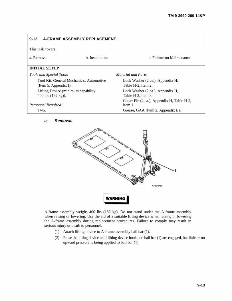
TM 9-3990-260-14&P
9-12. A-FRAME ASSEMBLY REPLACEMENT.
This task covers:
a. Removal b. Installation c. Follow-on Maintenance INITIAL SETUP Tools and Special Tools Material and Parts
Tool Kit, General Mechanic's: Automotive Lock Washer (2 ea.), Appendix H, (Item 5, Appendix I). Table H-2, Item 2. Lifting Device (minimum capability Lock Washer (2 ea.), Appendix H, 400 lbs (182 kg)). Table H-2, Item 3.
Cotter Pin (2 ea.), Appendix H, Table H-2, Personnel Required: Item 1.
Two. Grease, GAA (Item 2, Appendix E).
a. Removal.
A-frame assembly weighs 400 lbs (182 kg). Do not stand under the A-frame assembly when raising or lowering. Use the aid of a suitable lifting device when raising or lowering the A-frame assembly during replacement procedures. Failure to comply may result in serious injury or death to personnel.
(1) Attach lifting device to A-frame assembly bail bar (1). (2) Raise the lifting device until lifting device hook and bail bar (1) are engaged, but little or no
upward pressure is being applied to bail bar (1).
9-13
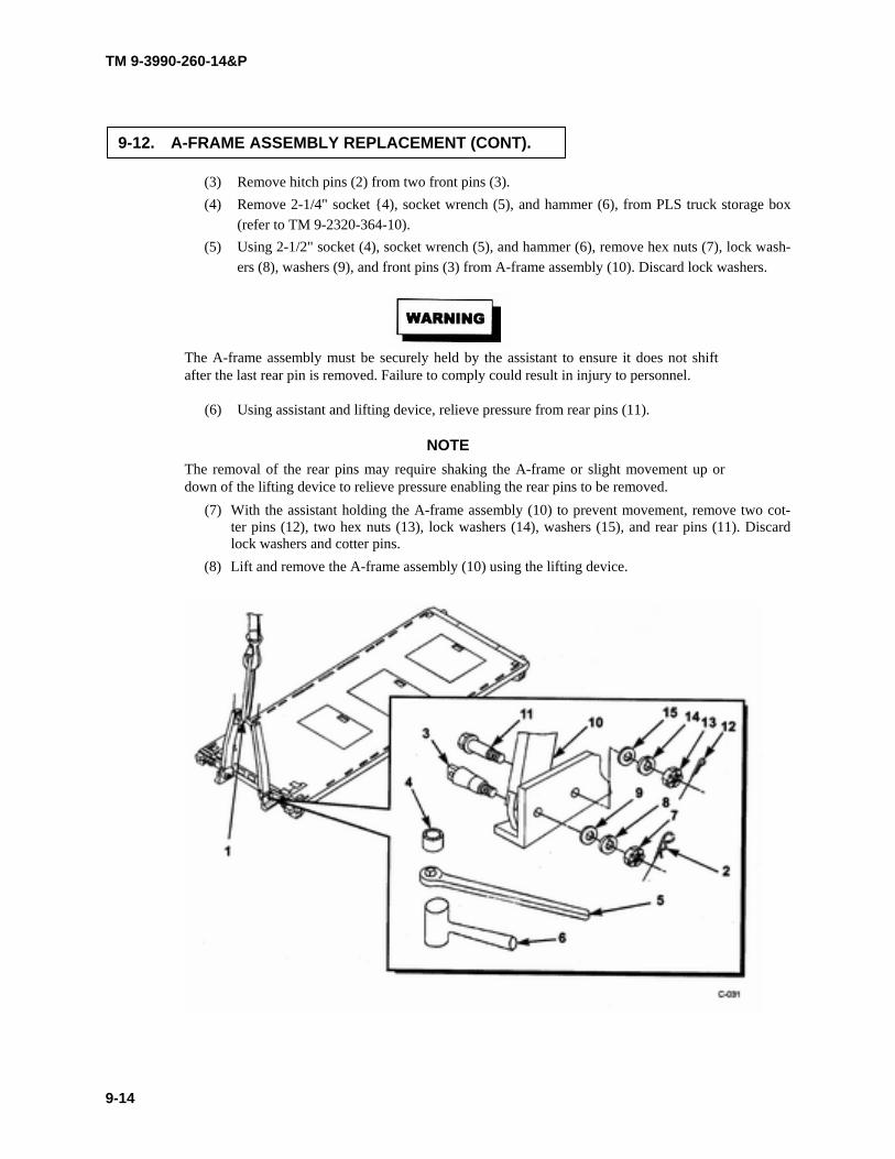
TM 9-3990-260-14&P
9-12. A-FRAME ASSEMBLY REPLACEMENT (CONT).
(3) Remove hitch pins (2) from two front pins (3). (4) Remove 2-1/4" socket {4), socket wrench (5), and hammer (6), from PLS truck storage box
(refer to TM 9-2320-364-10). (5) Using 2-1/2" socket (4), socket wrench (5), and hammer (6), remove hex nuts (7), lock wash-
ers (8), washers (9), and front pins (3) from A-frame assembly (10). Discard lock washers.
The A-frame assembly must be securely held by the assistant to ensure it does not shift after the last rear pin is removed. Failure to comply could result in injury to personnel.
(6) Using assistant and lifting device, relieve pressure from rear pins (11).
NOTE The removal of the rear pins may require shaking the A-frame or slight movement up or down of the lifting device to relieve pressure enabling the rear pins to be removed.
(7) With the assistant holding the A-frame assembly (10) to prevent movement, remove two cot- ter pins (12), two hex nuts (13), lock washers (14), washers (15), and rear pins (11). Discard lock washers and cotter pins.
(8) Lift and remove the A-frame assembly (10) using the lifting device.
9-14

TM 9-3990-260-14&P
b. Installation.
A-frame assembly weighs 400 lbs (182 kg). Do not stand under the A-frame assembly when raising or lowering. Use the aid of a suitable lifting device when raising or lowering the A-frame assembly during replacement procedures. Failure to comply may result in serious injury or death to personnel.
(1) Attach lifting device to A-frame assembly bail bar (1). (2) Check the A-frame assembly (10) to ensure that the holes where the front and rear pins (3
and 11) will be inserted and that the front and rear pins (3 and 11) are clean and completely free of dirt, sand, or other contamination. Grease the inside of the holes.
(3) Using lifting device, position A-frame assembly (10) and insert two rear pins (11) through the A-frame assembly (10). Install washers (15), lock washers (14) and hex nuts (13) finger tight.
(4) Tighten each rear pin (11) by turning the hex nut (13) clockwise using 2-1/4" socket (4) and socket wrench (5) until the hex nut (13) presses firmly against the lock washer (14) and the split in the lock washer (14) is fully compressed. Turn each hex nut (13) further until hole for cotter pin is exposed. Install two cotter pins (12).
(5) Apply a light film of grease (GAA) to front pins (3). (See Appendix K). (6) Using assistant and lifting device, position A-frame assembly (10) and insert two front pins
(3) through the A-frame assembly (10). Install washers (9), lock washers (8) and hex nuts (7) finger tight.
(7) Tighten each front pin (3) using 2-1/4" socket (4) and socket wrench (5). (8) Disconnect and remove lifting device. (9) Return the tools to the PLS stowage boxes.
c. Follow-on Maintenance. None.
9-15

TM 9-3990-260-14&P
9-13. TWISTLOCK REPLACEMENT. This task covers:
a. Removal b. Installation c. Follow-on Maintenance
INITIAL SETUP Tools and Special Tools Material and Parts
Tool Kit, General Mechanic's: Automotive Spring Pin, Appendix H, Table H-2, (Item 5, Appendix I). Item 5.
Grease, GAA (Item 2, Appendix E).
9-16

TM 9-3990-260-14&P
a. Removal.
NOTE This procedure shows replacement of one twistlock. Replacement is the same for all four twistlocks.
(1) Remove set screw (1), handle (2) and spacer (3) from shaft of bayonet (4). (2) Remove twistlock (5) assembly from deck (6) of CROP. (3) Remove retainer screw (7), spring (8) and ball (9) from locator block (10). (4) Remove spring pin (11), locator block (10) and bayonet (4) from twistlock (5). Discard
spring pin.
b. Installation. (1) Install bayonet (4) and locator blank (10) to twistlock (5) with spring pin (11).
(2) Install ball (9), spring (8), and retainer screw (7) to locator block (10).
(3) Install twistlock (5) assembly to deck (6) of CROP.
(4) Install spacer (3), handle (2) and set screw (1) to shaft of bayonet (4).
c. Follow-on Maintenance.
• Lubricate grease fitting in accordance with Appendix K.
9-17

TM 9-3990-260-14&P
9-14. ROLLER REPLACEMENT. This task covers: a. Removal b. Installation c. Follow-on Maintenance INITIAL SETUP
Tools and Special Tools Equipment Condition
Tool Kit, General Mechanic's: Automotive M3A1 CROP loaded onto PLS truck or raised (Item 5, Appendix I). on inspection jackstands.
Material and Parts Cotter Pin, (2 ea.), Appendix H, Table H-2, Item 10. Grease, GAA (Item 2, Appendix E).
9-18

TM 9-3990-260-14&P
a. Removal.
Support rollers during removal or rollers may drop causing injury to personnel.
NOTE This procedure shows replacement of one set of three rollers. Replacement is the same for both sets of rollers.
(1) Remove cotter pin (1) and washer (2) from roller pin (3). Discard the cotter pin (1). (2) While supporting each roller (4), remove the roller pin (3) and remaining four washers (2)
from bracket (5) and main beam (6).
b. Installation. (1) Apply GAA grease to roller pin (3). (2) While supporting each roller (4) in place, push roller pin (3) through main beam (6), rollers
(4), four washers (2), and bracket (5). (3) Install remaining washer (2) and install cotter pin (1), splitting cotter pin to prevent it from
falling out.
c. Follow-on Maintenance.
• Unload M3A1 CROP from PLS Truck.
9-19
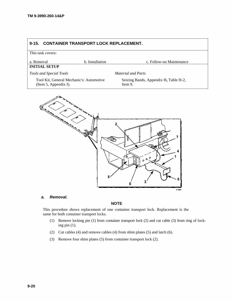
TM 9-3990-260-14&P
9-15. CONTAINER TRANSPORT LOCK REPLACEMENT.
This task covers: a. Removal b. Installation c. Follow-on Maintenance INITIAL SETUP
Tools and Special Tools Material and Parts
Tool Kit, General Mechanic's: Automotive Seizing Bands, Appendix H, Table H-2, (Item 5, Appendix I). Item 9.
a. Removal.
NOTE This procedure shows replacement of one container transport lock. Replacement is the same for both container transport locks.
(1) Remove locking pin (1) from container transport lock (2) and cut cable (3) from ring of lock- ing pin (1).
(2) Cut cables (4) and remove cables (4) from shim plates (5) and latch (6).
(3) Remove four shim plates (5) from container transport lock (2).
9-20

TM 9-3990-260-14&P
9-21
b. Installation.(1) Install four shim plates (5) to container transport lock (2).(2) Install cables (4) thru shim plates (5) and latch (6) and install seizing band (7).(3) Install cable (3) thru ring of locking pin (1) and install seizing band (8).(4) Position latch (6) in retracted position and install locking pin (1) thru shim plates (5) and latch (6).
c. Follow-on Maintenance. None.

TM 9-3990-260-14&P
9-22 Change 1
NOTE
• Wear plates will be scraped during normal usage. Wear plates do not require replacing if they are scraped.
• Perform a detailed inspection of the wear plates to determine the extent of damage and required repairs. If the wear plates are bent, torn, missing, and/or rivets are pulled out or missing, perform repairs as required. If the wear plate is raised or has bumps along its length, the method of repair is to flatten the raised area with a hammer and block of wood. Wear plates are aluminum. If the wear plate is bent out, saw off wear plate back to flat portion. Full replacement is not necessary.
a. Removal.NOTE
• Perform following steps for each wear plate.• The two small wear plates at rear of M3A1 CROP use two rivets.
(1) Remove rivets (1) from wear plate (2).(2) Remove wear plate (2) from side rail (3).
9-16. WEAR PLATE REPLACEMENT.
This task covers:
a. Removal b. Installation c. Follow-on Maintenance
INITIAL SETUP
Tools and Special Tools
Tool Kit, General Mechanic's: Automotive (Item 5, Appendix I). Drill, Electric, Portable (Item 2, Appendix I). Drill Set, Twist (Item 3, Appendix I).Tool Kit, Blind Rivet (Item 6, Appendix I).
Material and Parts
Rivet, Stud (7 ea.) Appendix H, Table H-2,Item 6.

TM 9-3990-260-14&P
b. Installation.
NOTE
• Perform following steps for each wear plate.
• The two small wear plates at rear of M3A1 CROP use two rivets. (1) Position wear plate (2) to side rail (3), alining holes in side rail (3) to holes in wear plate (2). (2) Install rivets (1) to wear plate (2) thru side rail (3).
c. Follow-on Maintenance. None.
9-23
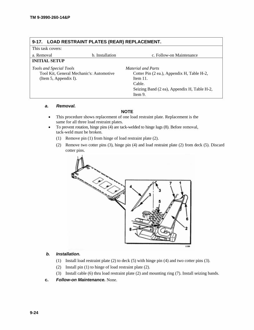
TM 9-3990-260-14&P
9-17. LOAD RESTRAINT PLATES (REAR) REPLACEMENT. This task covers: a. Removal b. Installation c. Follow-on Maintenance INITIAL SETUP
Tools and Special Tools Material and Parts Tool Kit, General Mechanic's: Automotive Cotter Pin (2 ea.), Appendix H, Table H-2, (Item 5, Appendix I). Item 11.
Cable. Seizing Band (2 ea), Appendix H, Table H-2, Item 9.
a. Removal. NOTE
• This procedure shows replacement of one load restraint plate. Replacement is the same for all three load restraint plates.
• To prevent rotation, hinge pins (4) are tack-welded to hinge lugs (8). Before removal, tack-weld must be broken. (1) Remove pin (1) from hinge of load restraint plate (2). (2) Remove two cotter pins (3), hinge pin (4) and load restraint plate (2) from deck (5). Discard
cotter pins.
b. Installation.
(1) Install load restraint plate (2) to deck (5) with hinge pin (4) and two cotter pins (3). (2) Install pin (1) to hinge of load restraint plate (2). (3) Install cable (6) thru load restraint plate (2) and mounting ring (7). Install seizing bands.
c. Follow-on Maintenance. None.
9-24

TM 9-3990-260-14&P
9-18. DOOR HOLDER REPLACEMENT. This task covers:
a. Removal b. Installation c. Follow-on Maintenance INITIAL SETUP Tools and Special Tools Equipment Condition
Tool Kit, General Mechanic's: Automotive Stowage box door opened. (Item 5, Appendix I).
a. Removal.
NOTE This procedures shows replacement of one door holder. Replacement is the same for all three door holders.
(1) Remove screw (1) and door holder (2) from stowage box (3). (2) Remove nut (4), screw (5), and door holder (6) from stowage box door (7).
b. Installation. (1) Install door holder (6) to stowage box door (7) with screw (5) and nut (4). (2) Install door holder (2) to stowage box (3) with screw (1).
c. Follow-on Maintenance. None.
9-25

TM 9-3990-260-14&P
9-19. BUMPER REPLACEMENT.
This task covers:
a. Removal b. Installation c. Follow-on Maintenance INITIAL SETUP Tools and Special Tools Material and Parts
Tool Kit, General Mechanic's: Automotive Lock Washer (2 ea), Appendix H, Table H-2, (Item 5, Appendix I). Item 4.
a. Removal.
NOTE • This procedure shows replacement of one bumper. Replacement is the same for the
other bumper. • It is necessary to hold bumper nut (1) while turning socket head screws with a 3/8-
inch hex key while loosening nuts (1).
(1) Remove two nuts (1), lock washers (2), flat washers (3) and socket head screws (4) from bumper (5). Discard lock washers.
(2) Remove bumper (5) from end rail (6). b. Installation.
(1) Position bumper (5) to end rail (6).
(2) Install two socket head screws (4), flat washers (3), lock washers (2) and nuts (1). c. Follow-on Maintenance. None.
9-26

TM 9-3990-260-14&P
9-20. STOWAGE BOX DOOR REPLACEMENT. This task covers:
a. Removal b. Installation c. Follow-on Maintenance INITIAL SETUP Tools and Special Tools Equipment Condition
Tool Kit, General Mechanic's: Automotive Stowage box door opened. (Item 5, Appendix I). Drill, Electric, Portable (Item 2, Appendix I). Material and Parts Drill Set, Twist (Item 3, Appendix I). Rivet, Stud (17 ea), Appendix H, Table H-2, Tool Kit, Blind Rivet (Item 6, Appendix I). Item 7.
a. Removal. NOTE
Perform the following steps for each of three stowage box doors. (1) Remove nine rivets (1) and door (2) from hinge (3). (2) Remove eight rivets (4) and hinge (3) from deck (5).
b. Installation. NOTE
Perform the following steps for each of three stowage box doors. (1) Install hinge (3) to deck (5) with eight rivets (4). (2) Install door (2) to hinge (3) with nine rivets (1).
9-27

TM 9-3990-260-14&P
c. Follow-on Maintenance. None.
9-28

TM 9-3990-260-14&P
10-1
CHAPTER 10
DIRECT SUPPORT MAINTENANCE(M3A1 CROP)
Para Contents Page
10-1 Common Tools and Equipment . . . . . . . . . . . . . . . . . . . . . . . . . . . . . . . . . . . . . . . . . . . . . . . . . . . . . . . . . 10-110-2 Special Tools, TMDE and Support Equipment . . . . . . . . . . . . . . . . . . . . . . . . . . . . . . . . . . . . . . . . . . . . . 10-110-3 Repair Parts . . . . . . . . . . . . . . . . . . . . . . . . . . . . . . . . . . . . . . . . . . . . . . . . . . . . . . . . . . . . . . . . . . . . . . . . 10-110-4 Service Upon Receipt . . . . . . . . . . . . . . . . . . . . . . . . . . . . . . . . . . . . . . . . . . . . . . . . . . . . . . . . . . . . . . . . 10-110-5 Introduction . . . . . . . . . . . . . . . . . . . . . . . . . . . . . . . . . . . . . . . . . . . . . . . . . . . . . . . . . . . . . . . . . . . . . . . . 10-210-6 Additional Inspection Criteria . . . . . . . . . . . . . . . . . . . . . . . . . . . . . . . . . . . . . . . . . . . . . . . . . . . . . . . . . . 10-210-7 General Welding Maintenance . . . . . . . . . . . . . . . . . . . . . . . . . . . . . . . . . . . . . . . . . . . . . . . . . . . . . . . . . 10-5
Section I. REPAIR PARTS, SPECIAL TOOLS, TEST, MEASUREMENT ANDDIAGNOSTIC EQUIPMENT (TMDE) AND SUPPORT EQUIPMENT
For authorized common tools and equipment, refer to the Modified Table of Organization and Equipment (MTOE)applicable to your unit.
Refer to Appendix B, the Maintenance Allocation Chart (MAC) and Appendix F, Repair Parts and Special ToolsList (RPSTL), to determine special tools, TMDE and support equipment for the M3A1 CROP. No fabricated toolsare needed.
Repair parts are listed and illustrated in the Repair Parts and Special Tools List (RPSTL), Appendix F, coveringUnit and Direct Support Maintenance for the M3A1 CROP.
Section II. SERVICE UPON RECEIPT
Chapter 9 contains service upon receipt instructions. Specific paragraphs are referenced for additional instructions.
a. Unpacking. Refer to paragraph 9-4a.
b. Servicing. Refer to paragraph 9-4b.
10-1. COMMON TOOLS AND EQUIPMENT.
10-2. SPECIAL TOOLS, TMDE AND SUPPORT EQUIPMENT.
10-3. REPAIR PARTS.
10-4. SERVICE UPON RECEIPT.

TM 9-3990-260-14&P
10-2 Change 1
Section III. DIRECT SUPPORT MAINTENANCE PROCEDURES
This section covers Direct Support Maintenance procedures for the M3A1 CROP. The following are general main-tenance procedures to keep in mind:
a. Removal and Disassembly. Do not separate banded, press-fitted, soldered, welded or riv-eted parts unless such removal is necessary to clean, inspect or test that part separately.
b. Inspection.(1) Inspect for loose, missing or damaged puts.
(2) Check for cracks, rust or pits, especially at weld points.
(3) Inspect all parts to determine if they conform to the wear limits, fits and tolerances estab-lished.
c. Lubrication. Refer to Appendix K for lubrication requirements.
d. Assembly. Refer to notes or diagrams made during disassembly to install new parts or reas-semble.
e. Installation. Pay special attention to requirements for installing cotter pins, spring pins, man-datory replacement items, and similar operations.
a. General. The M3A1 CROP is not an ISO compatible container used for intermodal shipping,therefore it does not require a CSC Safety Approval. However, it is used in conjunction with containers that are ISOcompatible and that do require a CSC Safety Approval. This paragraph provides inspection criteria similar to thatrequired to achieve CSC Safety Approval, but is to be used instead as the basis for determining the overall service-ability of M3A1 CROP.
b. Recommended Inspection Sequence. Inspection should be performed on the M3A1CROP while empty. Although any sequence of inspection is permissible, the sequence of the inspection containedherein is recommended. A complete examination, should be performed prior to acceptance. Acceptable crack lengthlimits are specified in Table 10-1.
(1) Markings and Data Plates. Check for appropriate markings and data plates.
(2) Overall Configuration. Check for any distortion of the overall configuration great enoughto preclude proper engagement of handling/lifting equipment, mounting and securing on aPLS truck or trailer, and insertion into an ISO container. If alignment is in question, use ameasuring tape to check dimensions in accordance with Para 6-13.
(3) Exterior Sides and Ends. Examine the M3A1 CROP exterior on all sides and ends for anydefects on main structural components or unacceptable damage on fixed and removableload restraint plates.
(4) Understructure. Position the M3A1 CROP on jackstands to enable safe viewing of theunderstructure. Examine the corner twistlock apertures, side and end rails, crossmembersand forklift tunnels for defects.
10-5. INTRODUCTION.
10-6. ADDITIONAL INSPECTION CRITERIA.

TM 9-3990-260-14&P
Change 1 10-3
(5) A-frame Assembly. Check for any distortion of the A-frame assembly great enough to pre-clude safe movement using the PLS truck and trailer. Check for excessive wear of the frontpins and rear pins. Excessive wear of these items requires their replacement. Check bailbar for excessive wear or cracks in weldment.
(6) Deck. Check condition of deck floor for defects. Check stowage boxes in deck for service-ability and availability of BII.
(7) Deck Flooring Gaps. Excessive gaps in flooring may be determined by use of a 1 inch(2.54 cm) wide by 1/16 inch (1/59 mm) thick feeler gauge. Any suitable strip of metal maybe used.
c. Suggested Tools and Equipment.(1) Straight Edge. A wire, string or other form of a straight edge is needed to determine
whether any portion of the M3A1 CROP protrudes past the outside surfaces of the siderails, which would interfere with insertion ad extraction of the M3A1 CROP from an ISOshipping container.
(2) Measuring Tape (Ruler). A measuring tape (ruler) is required to check dimensional toler-ances.
(3) Welder's Hammer. A welder's hammer (NSN 5120-00-240-3096 or equivalent) is helpfulin determining the strength of welds or metal structural components.
(4) Inspection Stands. Jackstands (Item 4, Appendix I) provide a safe means for supporting theempty M3A1 CROP to enable proper viewing of the understructure. DoD personnelshould also refer to service-specific safety guidelines about "Working Under a SuspendedLoad".
(5) Flashlight. A flashlight improves visual acuity, especially during examination of therecesses of the understructure.
(6) Chalk. Marking (circling) location of defects with chalk as they are discovered facilitatespreparation of inspection reports and helps maintenance personnel locate areas to berepaired.
d. Primary Structural Components. An M3A1 CROP with any major defect in any compo-nent of its primary structure is unacceptable. For purposes of this criteria, primary (main) structural components(members) include: twistlock housings, A-frame assembly, roller assembly brackets, forklift pockets, and main rails.
(1) Major Defects. A major defect includes:(a) A dent or bend in any primary structural component that prevents the CROP from
loading;(b) A crack, break, cut, tear, puncture or corrosive failure in any primary structural com-
ponent;(c) A missing, cracked or broken weld at the juncture between any primary structural
component;(d) More than two splices or an improper splice of any one floor crossmember;(e) Any damage or degradation within a component that could place any person in dan-
ger during subsequent handling, stacking or transport of the M3A1 CROP;(f) More than one splice or an improper splice (such as a lapped splice) in an end rail.
(2) Acceptable Welding Pattern. Welding patterns conforming to the original manufacturer'sdesign are acceptable. Only abnormal welding patterns due to damage and/or improperrepair are cause for rejection. Inspection should be directed at looking for broken junc-tures or welded repairs that are not consistent with other similar welds of the M3A1 CROP.

TM 9-3990-260-14&P
10-4
(3) Acceptable Splicing. A splice is any repair of a primary structural member that replacesmaterial without complete replacement of the member. Areas repaired by straightening andbead welding are not to be construed as splices. Gussets, backup plates or other reinforce-ment (protector) plates are not to be construed as splices. An acceptable splice is a minimumof 6 in. (15 cm) long and is a butt-welded insert. If a splice would end within 12 in. (30 cm)of another weld, it must be extended to that weld. An acceptable splice is flush fitting andrestores the original size and cross-sectional profile of the repaired component. Backupplates installed on the backside of a splice are permissible if the backup plate extends a min-imum of 6 in. (15 cm) beyond each end of the splice.
(4) A-frame Assembly. The A-frame assembly front and rear threaded pins must not be seized,twisted, broken, missing, or otherwise inoperable. Any twist, dent, or bend to any of the pinsthat renders the A-frame assembly inoperable is cause for rejection. The A-frame assemblymust not be bent or twisted in such a manner that it renders the A-frame assembly inopera-ble.
(5) Tiedown and Multipurpose Provision Rings. Provisions used for attachment of web straps orother cargo restraint devices must be in working order. Tiedown bars and securing weldpoints and multipurpose provision rings that are deformed or broken a cause for rejection.
(6) Cargo Deck. An M3A1 CROP is unacceptable if the flooring has any of the following defi-ciencies:
(a) Any protrusion above the top surface of the deck;
(b) Any loose or missing deck plate;
(c) Deck not free of debris or residue from a previous cargo;
(d) Deck or area of deck covered with hazardous or flammable fluid.
e. Damage and Repair.(1) Patch. Any repair of a deck panel that adds or replaces material without complete replace-
ment of the panel. An acceptable patch is of permanent design, of similar material and con-figuration and weather-proof. Patch is a generic term which, for the purposes of thisinspection criteria, is reserved exclusively for repairs of nonprimary components such asdeck panels.
(2) Splice. Any repair of a primary (main) structural component (member) that replaces materialwithout complete replacement of the member. Gussets, backup plates or other reinforcement(protector) plates are not to be construed as splices. Splice is a regulatory repair term which,for the purposes of this inspection criteria, is reserved exclusively for repairs on componentsof the primary structure.
(3) Gusset. Reinforcement plate, usually triangular in shape, welded between adjacent compo-nents to reinforce the structure and provide added resistance to handling damage.
(4) Backup Plate. A reinforcement (doubler) plate installed on the backside of a structural com-ponent and not on the exterior of the component's profile. The backup plate serves to stiffenand strengthen the component.
(5) Insert. A specific type of repair in which replacement material is fitted flush with the originalcomponent and only a partial profile of the component's cross section is replaced.
10-6. ADDITIONAL INSPECTION CRITERIA (CONT).

TM 9-3990-260-14&P
Change 1 10-5
(6) Section. A specific type of repair in which replacement material is fitted flush with theoriginal component and the entire profile of the component's cross section is replaced.
(7) Hole. A circular penetrating puncture through any part of the CROP.
(8) Pinhole. A small hole less than 1/8 in. (3.18 mm) in diameter. A pinhole typically resultsfrom a tiny skip or porosity in a weld and usually is only detected during a light leak test.
(9) Corrosive Failure. Corrosive failure (galvanic or electrolytic) is determined when the cor-roded metal can be punched by striking the area lightly with a welder's hammer.
(10) Caulking. A sealant compound used to provide water tightness around patches in panels,around riveted seams, in holes of pop rivets, in joints between dissimilar metals, in gapsbetween floor board edges and in gaps where the floor boards adjoin the interior wall.
(11) Undercoating. Bituminous material or other waterproof coating brushed or sprayed on theentire underside of the container floor to protect all of the metal understructure against cor-rosion.
Underneath the CARC paint, the M3A1 CROP is completely galvanized with zinc. Zinc fumes,released by the burning of the zinc during welding repairs, are extremely toxic. Welding per-sonnel must exercise extreme caution or wear respirators, when performing welding repairs.
NOTEWhen weldment cracks are discovered, it is recommended that they be repaired at the next ser-vice interval to prevent the length of the crack from increasing and to minimize repair. The fol-lowing inspection procedures are to be considered as guidelines only. Any cracks discoveredduring the inspections considered more significant, especially from a safety stand point shouldbe referred to the supervisor for weld repair decisions. This would include cracks identified inany main structural areas (main frame and main rail flanges) and cracks that have opened andcould lengthen rapidly during loading/unloading operations.
a. Weldment Points. Thoroughly inspect all weldments for cracks, chips or other damage.Areas include the end structure assembly, pin blocks, main beams, center tubes, cross beams, front and end beams,ISO twistlock housings, multipurpose provision rings and mounting brackets and D-ring mounting bars. Particularattention should be paid to the difference between a crack in the coatings and a crack in a weld or parent material.Suspected cracks in welds or parent material should be confirmed by using non-destructive examination techniques(e.g. ultra sound test or Zyglow inspection). Inspect welds for acceptable crack length limits using the followingguidelines:
10-7. GENERAL WELDING MAINTENANCE.

TM 9-3990-260-14&P
10-6 Change 1
Table 10-1. Acceptable Crack Length Limits
(1) Acceptable Welding Patterns. Welding patterns conforming to the original manufacturer'sdesign are acceptable. Only abnormal welding patterns due to damage and/or improperrepair are cause for rejection. Inspection should be directed at looking for broken junc-tures or welded repairs that are not consistent with other similar welds of the M3A1 CROP.
(2) Acceptable Splicing. A splice is any repair of a primary structural member that replacesmaterial without complete replacement of the member. Areas repaired by straighteningand bead welding are not to be construed as splices. Gussets, backup plates or other rein-forcement (protector) plates are not to be construed as splices. An acceptable splice is aminimum of 6 in. (15 cm) long and is a butt-welded insert. If a splice would end within 12in. (30 cm) of another weld, it must be extended to that weld. An acceptable splice is flushfitting and restores the original size and cross-sectional profile of the repaired component.Backup plates installed on the backside of a splice are permissible if the backup plateextends a minimum of 6 in. (15 cm) beyond each end of the splice.
10-7. GENERAL WELDING MAINTENANCE (CONT).
Areas to be Inspected Acceptable Crack Length Limits
1. Pin Blocks and Center Tube Welds and Parent Material
Less than 1/4 inch (6 mm)
2. Cross Beams A crack should be repaired after it has reached 3/4 inch (19 mm).The total length of cracks on a single crossmember should notexceed 2 inches (51 mm). When cracks are present on severalcrossmembers, action should be taken to repair them at the nextservice. If a crossmember is completely missing, repairs shouldbe made prior to use.
3. Front and Rear Beams Less than 1/4 inch (6 mm)
4. Main Beams (Note: Bends to bottom flange and main beams are normal.)
Cracks in the parent material or welds between the main beamsand cross beams cannot exceed 3/4 inch (19 mm).
5. Twistlocks Due to the loads twistlocks can see during retrograde transportmode, any cracks in the twistlock housing should be repairedbefore reaching 3/4 inch (19 mm).
6. A-Frame A crack should be repaired before it has reached 2 inches (5 cm).The combined length of multiple cracks at any one locationshould not exceed 4 inches (10 cm).
7. Hookbar (Welds securing the hookbar casting on the A-frame).
Cracks should be repaired prior to reaching 1 inch (2 cm) inlength. The combined length of multiple cracks at this locationshould not exceed 1-1/2 inches (4 cm).
8. Multipurpose D-Rings Due to the high loads that these fittings can see in transportmode, any crack should be repaired before reaching 1/2 inch (1cm) in length. The combined length of multiple cracks at any onelocation should not exceed 1/2 inch (1 cm). This applies to crackspresent in the adjoining structure also.
9. Decking The maximum allowable single crack in the deck seams is 6inches (15 cm) long. When multiple cracks are present, the com-bined length of the cracks cannot exceed 10 inches (25 cm).

TM 9-3990-260-14&P
Change 1 10-7
(3) A-Frame. Solid welds in the A-frame area are necessary to ensure safe loading and unload-ing of the CROP.
(4) Hookbar. These welds are located at the base of the hookbar casting on the A-frame of theM3A1 CROP. These welds secure the hookbar to the A-frame and are subjected to a signif-icant portion of the total load during loading and unloading operations.
(5) MIL-STD-209 Multipurpose Rings. The large D-rings of the CROP are used for transporta-tion. They may be used to secure the CROP to a trailer or railcar.
(6) Crossmembers. These welds are located at the junction of the crossmember and the mainrails.
(7) Decking.(8) Main Rails. The main rails provide a major portion of the load carrying capacity of the
CROP. They support a portion of the load while loaded on the truck and trailer.
b. Removing the CARC Paint Primer and Galvanizing Coatings Prior to Weld Repair.NOTE
There are three options to repair a weld: 1) oxyacetylene torch; 2) sandblasting, or; 3) surfacegrinding. Use one of these options to remove CARC paint, primer and galvanizing prior to weldrepair.
Use a respirator when removing paint, primer and galvanizing with an oxyacetylene torch becauseof the toxic gases.
NOTEThe galvanizing must be heated to 860°F (460°C) before it will melt.
(1) Option One. Use an oxyacetylene torch and a stainless steel wire brush to remove the paint,primer and galvanizing.(a) Using oxyacetylene torch, heat galvanizing to 860°F (460°C).
NOTEUse the brush within 1.5 inches (38 mm) on both sides of repair area.(b) Once the galvanizing starts to melt, use a stainless steel wire brush to remove paint,
primer and galvanizing.(2) Option Two.
(a) Cover the area around the weld repair with masking tape (about one inch on each sideof the anticipated weld deposit). This will protect the other areas of the CARC finishnot being repaired.
(b) Use sandblaster to remove paint, primer and galvanizing.(3) Option Three. Use surface grinder (hand grinder) to remove paint, primer and galvanizing
within one inch on either side of the anticipated weld deposit.
CAUTION
Do not weld the CROP while on trailer or truck or damage to equipment may result.
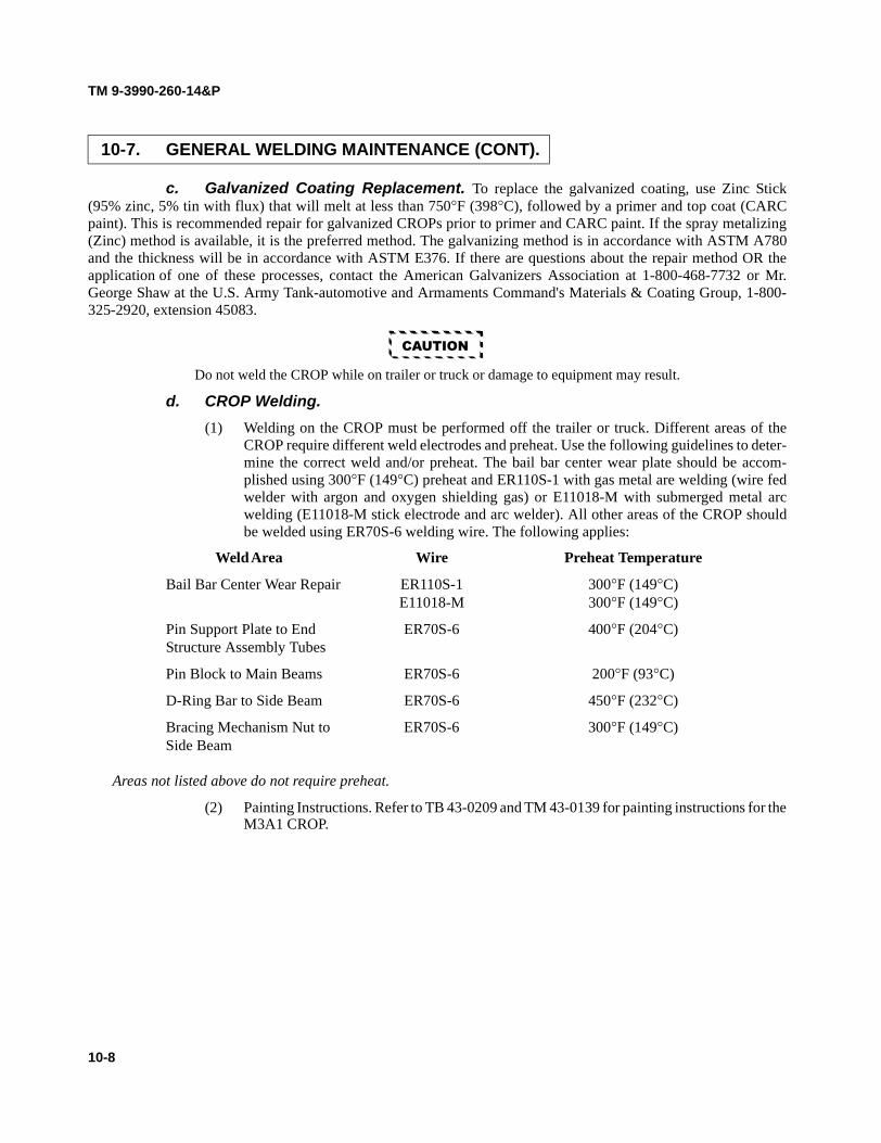
TM 9-3990-260-14&P
10-8
c. Galvanized Coating Replacement. To replace the galvanized coating, use Zinc Stick(95% zinc, 5% tin with flux) that will melt at less than 750°F (398°C), followed by a primer and top coat (CARCpaint). This is recommended repair for galvanized CROPs prior to primer and CARC paint. If the spray metalizing(Zinc) method is available, it is the preferred method. The galvanizing method is in accordance with ASTM A780and the thickness will be in accordance with ASTM E376. If there are questions about the repair method OR theapplication of one of these processes, contact the American Galvanizers Association at 1-800-468-7732 or Mr.George Shaw at the U.S. Army Tank-automotive and Armaments Command's Materials & Coating Group, 1-800-325-2920, extension 45083.
CAUTION
Do not weld the CROP while on trailer or truck or damage to equipment may result.
d. CROP Welding.(1) Welding on the CROP must be performed off the trailer or truck. Different areas of the
CROP require different weld electrodes and preheat. Use the following guidelines to deter-mine the correct weld and/or preheat. The bail bar center wear plate should be accom-plished using 300°F (149°C) preheat and ER110S-1 with gas metal are welding (wire fedwelder with argon and oxygen shielding gas) or E11018-M with submerged metal arcwelding (E11018-M stick electrode and arc welder). All other areas of the CROP shouldbe welded using ER70S-6 welding wire. The following applies:
Weld Area Wire Preheat Temperature
Bail Bar Center Wear Repair ER110S-1 300°F (149°C)E11018-M 300°F (149°C)
Pin Support Plate to End ER70S-6 400°F (204°C)Structure Assembly Tubes
Pin Block to Main Beams ER70S-6 200°F (93°C)
D-Ring Bar to Side Beam ER70S-6 450°F (232°C)
Bracing Mechanism Nut to ER70S-6 300°F (149°C)Side Beam
Areas not listed above do not require preheat.
(2) Painting Instructions. Refer to TB 43-0209 and TM 43-0139 for painting instructions for theM3A1 CROP.
10-7. GENERAL WELDING MAINTENANCE (CONT).

TM 9-3990-260-14&P
A-1
APPENDIX A
REFERENCES
Indexes should be consulted frequently for latest changes or revisions of references given in this appendix and for new publications relating to material covered in this publication.
Military Publications Indexes:
Consolidated Index of Army Publications and Blank Forms . . . . . . . . . . . . . . . . . . . . . . . . . . . . DA Pam 25-30
Refer to DA Pam 750-8, the Army Maintenance Management System (TAMMS), for instructions on the use ofmaintenance forms pertaining to the M3 CROP and M3A1 CROP.
The Army Maintenance Management System (TAMMS). . . . . . . . . . . . . . . . . . . . . . . . . . . . . . . DA Pam 750-8
Recommended Changes to Publications and Blank Forms. . . . . . . . . . . . . . . . . . . . . . . . . . . . . DA Form 2028
Equipment Inspection and Maintenance Worksheet . . . . . . . . . . . . . . . . . . . . . . . . . . . . . . . . . . . DA Form 2404
Maintenance Request . . . . . . . . . . . . . . . . . . . . . . . . . . . . . . . . . . . . . . . . . . . . . . . . . . . . . . . . . . DA Form 2407
Equipment Control Record . . . . . . . . . . . . . . . . . . . . . . . . . . . . . . . . . . . . . . . . . . . . . . . . . . . . . . DA Form 2408-9
Preventive Maintenance Schedule and Record . . . . . . . . . . . . . . . . . . . . . . . . . . . . . . . . . . . . . . . DD Form 314
Processing and Deprocessing Record for Shipment,
Storage, and Issue of Vehicles and Spare Engines. . . . . . . . . . . . . . . . . . . . . . . . . . . . . . . . . . . . . DD Form 1397
Product Quality Deficiency Report . . . . . . . . . . . . . . . . . . . . . . . . . . . . . . . . . . . . . . . . . . . . . . . . SF Form 368
Multiservice Tactics, Techniques and Procedures for Chemical, Biological, Radiological,
and Nuclear Decontamination . . . . . . . . . . . . . . . . . . . . . . . . . . . . . . . . . . . . . . . . . . . . . . . . . . . FM 3-11.5
.
A-1. GENERAL
A-2. FORMS.
A-3. FIELD MANUALS.
TM 9-3990-260-14&P
A-2 Change 1
Materials Used for Cleaning, Preserving, Abrading, and CementingOrdnance Material and Related Materials Including Chemicals . . . . . . . . . . . . . . . . . . . . . . . . . . TM 9-247
Operator's, Organizational, and Direct Support and General Support Maintenance Manual(Including Repair Parts and Special Tools List), for Load Handling System, Heavy Expanded Mobility Tactical Trucks (HEMTT) . . . . . . . . . . . . . . . . . . . . . . . . . . . . . . . . . . . . . . . . . . . . . . . . TM 9-2320-304-14&P
Operator's Manual, Truck, Tractor Palletized Load System (PLS) . . . . . . . . . . . . . . . . . . . . . . . . TM 9-2320-364-10
Operator's, Unit, Direct Support, and General SupportMaintenance Manual, Trailer, Palletized Load System (PLS) . . . . . . . . . . . . . . . . . . . . . . . . . . . TM 9-2330-385-14
Painting Instructions. . . . . . . . . . . . . . . . . . . . . . . . . . . . . . . . . . . . . . . . . . . . . . . . . . . . . . . . . . . . TM 43-0139
Procedures for Destruction of Tank-Automotive Equipment to Prevent Enemy Use (U.S. Army Tank-Automotive and Armaments Command). . . . . . . . . . . . . . . . . . . . TM 750-244-63
Color, Marking, and Camouflage Painting of Military Vehicles, Construction Equipmentand Material Handling Equipment . . . . . . . . . . . . . . . . . . . . . . . . . . . . . . . . . . . . . . . . . . . . . . . . TB 43-0209
Standard for Overseas Shipment or Domestic Issue of Special Purpose Vehicles. . . . . . . . . . . . . TM 9-2300-281-35
Operator's Circular for Welding Theory and Application . . . . . . . . . . . . . . . . . . . . . . . . . . . . . . . TC 9-237
Requisition and Issue of Supplies and Equipment . . . . . . . . . . . . . . . . . . . . . . . . . . . . . . . . . . . . AR 725-50
Packaging of Army Materiel for Shipment and Storage . . . . . . . . . . . . . . . . . . . . . . . . . . . . . . . . AR 746-1
Marking, Packing, and Shipment of Supplies and Equipment . . . . . . . . . . . . . . . . . . . . . . . . . . . AR 746-2
Army Materiel Maintenance Policy and Retail Maintenance Operations . . . . . . . . . . . . . . . . . . . AR 750-1
Container Inspection Handbook for Commercial and Military Intermodal Containers . . . . . . . . MIL-HDBK-138
A-4. TECHNICAL MANUALS.
A-5. MISCELLANEOUS PUBLICATIONS.

TM 9-3990-260-14&P
APPENDIX B
MAINTENANCE ALLOCATION CHART (MAC)
Section I. INTRODUCTION
B-1. GENERAL.
a. This section provides a general explanation of all maintenance and repair functions authorized at various maintenance levels.
b. The Maintenance Allocation Chart (MAC) in Section II designates overall authority and responsi- bility for the performance of maintenance functions on the Container Roll-In/Out Platform (CROP) M3 and M3Al.
c. Section III lists the tools and test equipment required for each maintenance function as referenced from Section II.
d. Section IV lists remarks (identified by an alphabetic code in column 6 of MAC) to provide a ready reference to the definition of the remarks.
B-2. MAINTENANCE FUNCTIONS.
Maintenance functions will be limited to and defined as follows:
a. Inspect. To determine the serviceability of an item by comparing its physical, mechanical, and/or electrical characteristics with established standards through examination (e.g., by sight, sound, or feel).
b. Test. To verify serviceability by measuring the mechanical, pneumatic, hydraulic, or electrical characteristics of an item and comparing those characteristics with prescribed standards.
c. Service. Operations required periodically to keep an item in proper operating condition, i.e., to clean (includes decontaminate, when required), to preserve, to drain, to paint, or to replenish fuel, lubricants, chem- ical fluids, or gases.
d. Adjust. To maintain or regulate, within prescribed limits, by bringing into proper or exact posi- tion, or by setting the operating characteristics to specified parameters.
e. Align. To adjust specified variable elements of an item to bring about optimum or desired perfor- mance.
f. Calibrate. To determine and cause corrections to be made or to be adjusted on .instruments or test, measuring, and diagnostic equipment used in precision measurement. Consists of comparison of two instruments, one of which is a certified standard of known accuracy, to detect and adjust any discrepancy in the accuracy of the instrument being compared.
g. Remove/Install. To remove and install the same item when required to perform service or other maintenance functions. Install may be the act of emplacing, seating or fixing into position, a spare, repair part, or module (component or assembly) in a manner to allow the proper functioning of an equipment or system.
h. Replace. To remove an unserviceable item and install a serviceable counterpart in its place. "Replace" is authorized by the MAC and is shown as the 3rd position code of the SMR code.
B-1

TM 9-3990-260-14&P
B-2. MAINTENANCE FUNCTIONS (CONT).
i. Repair. The application of maintenance services, including fault location/troubleshooting, removal/installation, an disassembly/assembly procedures, and maintenance actions to identify troubles and restore serviceability to an item by correcting specific damage, fault, malfunction, or failure in a part, subassembly, mod- ule (component or assembly), end item, or system.
(1) Service includes inspection, testing, service, adjustment, alignment, calibration and/or replacement.
(2) Fault locate/troubleshooting is the process of investigating and detecting the cause of equip- ment malfunctioning, the act of isolating a fault within a system or Unit Under Test (UUT).
(3) Disassemble/Assemble encompasses the step-by-step taking apart (or breakdown) of a spare/ functional group coded item to the level of its least component identified as maintenance sig- nificant (i.e., assigned an SMR code) for the category of maintenance under consideration.
(4) Actions include welding, grinding, riveting, straightening, facing, remachining and/or resur- facing.
j. Overhaul. The maintenance effort (service/action) prescribed to restore an item to a completely serviceable/operational condition as required by maintenance standards in appropriate technical publications (i.e., DMWR). Overhaul is normally the highest degree of maintenance performed by the Army. Overhaul does not nor- mally return an item to like new condition.
k. Rebuild. Consists of those services/actions necessary for the restoration of unserviceable equip- ment to a like-new condition in accordance with original manufacturing standards. Rebuild is the highest degree of material maintenance applied to Army equipment. The rebuild operation includes the act of returning to zero those age measurements (hours/miles, etc.) considered in classifying Army equipment/components.
B-3. EXPLANATION OF COLUMNS IN SECTION II.
a. Column 1, Group Number. Column 1 lists functional group code numbers, the purpose of
which is to identify maintenance significant components, assemblies, subassemblies, and modules with the next higher assembly. End item group number shall be "00".
b. Column 2, Component/Assembly. Column 2 contains the names of components, assemblies, subassemblies and modules for which maintenance is authorized.
c. Column 3, Maintenance Function. Column 3 lists the functions to be performed on the item listed in column 2.
B-2

TM 9-3990-260-14&P
B-3
d. Column 4, Maintenance Level. Column 4 specifies, by the listing of a work time figure in theappropriate subcolumn(s), the level of maintenance authorized to perform the function listed in Column 3. This fig-ure represents the active time required to perform that maintenance function at the indicated level of maintenance.If the number or complexity of the tasks within the listed maintenance function vary at different maintenance lev-els, appropriate work time figures will be shown for each level. The work time figure represents the average timerequired to restore an item (assembly, subassembly, component, module, end item, or system) to a serviceable con-dition under typical field operating conditions. This time includes preparation time (including any necessary disas-sembly/assembly time), troubleshooting/fault location time, and quality assurance/quality control time in additionto the time required to perform the specific tasks identified for the maintenance functions authorized in the Mainte-nance Allocation Chart. The symbol designations for the various maintenance levels are as follows:
C Operator or Crew
O Unit Maintenance
F Direct Support Maintenance
H General Support Maintenance
e. Column 5, Tools and Equipment. Column 5 specifies, by code, those common tool sets (notindividual tools) and special tools, TMDE, and support equipment required to perform the designated function.
f. Column 6, Remarks. This column shall, when applicable, contain a letter code in alphabeticorder, which shall be keyed to the remarks contained in Section IV.
a. Column 1, Reference Code. The tool and test equipment reference code correlates with a codeused in the MAC, Section II, Column 5.
b. Column 2, Maintenance Level. The lowest category of maintenance authorized to use the toolor test equipment.
c. Column 3, Nomenclature. Name or identification of the tool or test equipment.
d. Column 4, National Stock Number. The national stock number of the tool or test equipment.
e. Column 5, Tool Number. The manufacturer's part number.
a. Column 1, Reference Code. An alphabetic code listed in the sixth column of the MAC andfirst column of the Remarks section to identify remarks made to the MAC.
b. Column 2, Remarks. The complete text of the remarks made to the MAC.
B-4. EXPLANATION OF COLUMNS IN TOOL AND TEST EQUIPMENT REQUIREMENTS, SECTION III.
B-5. EXPLANATION OF COLUMNS IN REMARKS, SECTION IV.

TM 9-3990-260-14&P
B-4 Change 1
Section II. MAINTENANCE ALLOCATION CHART (MAC) FOR CONTAINERROLL-IN/OUT PLATFORM (M3 AND M3A1 CROP)
Group Number
Component/Assembly
MaintenanceFunction
Maintenance Level
Tools and Equipment Remarks
Field Sustainment
Unit DS GS Depot
C O F H D
33 SPECIAL PURPOSE KITS
3301 Reusable Shipping Containers
M3 CROP InspectRepair
* ** *
11,2,3
AA
Roller Twistlock
ReplaceReplaceRepair
***
1,21,21,2
AAA
End Structure Assembly Replace * 1 A
Bracing Mechanism Replace * 1 A
M3A1 CROP InspectRepair
* ** *
11,2,3
AA
Roller Replace * 1,2 A
Twistlock ReplaceRepair
**
1,21,2
AA
A-Frame Assembly Replace * 1 A
Container Transport Lock Replace * 1 A
Wear Plate Replace * 1,2 A
Rear Cargo Restraint Plates
Replace * 1 A

TM 9-3990-260-14&P
Section III. TOOL AND TEST EQUIPMENT REQUIREMENTS FOR CONTAINER ROLL-IN/OUT PLATFORM (M3 AND M3A1 CROP)
Tool or Test Equipment Ref Code
Maintenance
Level
Nomenclature
National Stock
Number
Tool Number
1 O Tool Kit, General Mechanic's: Automotive 5180-00-177-7033 SC 5180-95-N26 2 O Shop Equipment, Automotive Maintenance
and Repair: Common No. 1. 4910-00-754-0654 SC 4910-95-A74
3 F, H Shop Equipment, Field Maintenance, Basic, Less Power
4910-00-754-0705 SC 4910-95-A31
Section IV. REMARKS
Reference Code
Remarks
A No specific time established. Times required for repair or replacement will depend on extent of work required.
B-5 /(B-6 blank)


TM 9-3990-260-14&P
Change 1 C-1/(C-2 blank)
APPENDIX C
COMPONENTS OF END ITEM (COEI) AND BASIC ISSUE ITEMS (BII) LISTS
The following is a list of Basic Issue Items (BII) for the Container Roll-In/Out Platform (CROP) M3 and M3A1.There are no Components of End Item (COEI) authorized for this equipment.
Table C-1. Basic Issue Items (BII)
C-1. INTRODUCTION.
(1) (2) (3) (4) (5) Illus
Number National Stock
Number Description
(CAGEC) Part NumberUsable
On Code U/MQty Rqr
1 5340-01-504-2426 Web Strap Assembly (31272) 12468753
078079
ea 14
2 5310-01-460-7706 Bar, Pin (19200) 12468755
078 ea 1
3 5120-00-293-3396 Hammer, Wooden Handle, Soft Faced (49181) KT171714
078079
ea 1
4 5120-00-199-7771 Socket, 2-1/4 inch, 3/4 inch Drive (8Z799) H1272
078079
ea 1
5 5120-00-249-1076 Socket, Socket Wrench, 3/4 inch Drive (77053) 9649
078079
ea 1


TM 9-3990-260-14&P
Change 1 D-1/(D-2 blank)
APPENDIX D
ADDITIONAL AUTHORIZATION LIST (AAL)
Table D-1. Additional Authorization List (AAL)
(1) (2) (3) (4) (5)
Illus Number
National Stock Number
Description(Cagec) Part Number
Usable On Code U/M
Qty Rqr
1 3990-01-491-4714 Cargo Net (20 ft L X 90 inch W)(098P0) B9154-90240-2R-24C
078079
EA 1
2 3990-01-491-4725 Cargo Net (24 ft L X 124 inch W)(098P0) B9154-120288-2R-24C
078079
EA 1
3 2540-01-471-5071 Extension, Hook Arm (OBJH4) 12468660
078079
EA 1
4 2590-01-533-8676 Ramp, Loading Vehicle (RH)(OBJH4) 12468623-1
078079
EA 1
5 2590-01-539-2857 Ramp, Loading Vehicle (LH)(OBJH4) 12468623-2
078079
EA 1


TM 9-3990-260-14&P
E-1
APPENDIX E
EXPENDABLE AND DURABLE ITEMS LIST
Section I. INTRODUCTION
This appendix lists expendable supplies and materials you will need to operate and maintain the M3 CROP andM3A1 CROP. These items are authorized to you by CTA 50-970, Expendable Items (Except Medical, Class V,Repair Parts and Heraldic Items) or CTA 8-100, Army Medical Department Expendable/Durable Items.
a. Column (1) - Item Number. This number is assigned to the entry in the listing and is referencedin the narrative task box to identify the material (e.g., Sealing Compound Item 11, Appendix E).
b. Column (2) - Level. This column identifies the lowest level of maintenance that requires thelisted items.
C Operator
O Unit Maintenance
F Direct Support Maintenance
H General Support Maintenance
c. Column (3) - National Stock Number. This is the National Stock Number assigned to theitem; use it to request or requisition the item.
d. Column (4) - Description. Indicates the Federal item name and, if required, a description toidentify the item. The last line for each item indicates the Commercial and Government Entity (CAGE) code inparentheses followed by the part number.
e. Column (5) - Unit of Measure (U/M). Indicates the measure used in performing the actualmaintenance function. This measure is expressed by a two-character alphabetical abbreviation (e.g., ea, in, pr). Ifthe unit of measure differs from the unit of issue, requisition the lowest unit of issue that will satisfy your require-ments.
E-1. SCOPE.
E-2. EXPLANATION OF COLUMNS.

TM 9-3990-260-14&P
E-2 Change 1
Section II. EXPENDABLE AND DURABLE ITEMS LIST
(1) (2) (3) (4) (5)
Item Number
Level National StockNumber Description U/M
1 C 7902-00-044-9281 Cloth, Lint-Free, 10 lb box (MIL-C-85043) Lb
2 C,O,F Grease, Automotive and Artillery (GAA) (MIL-G-10924)
9150-01-197-77899150-01-197-7693 9150-01-197-7690 9150-01-197-7692 9150-01-197-7691
2.5 oz tube 14 oz cartridge 1.75 lb can 35 lb can 120 lb drum
Oz Oz LbLb Lb
3 C,O Cleaning Compound, Solvent (MIL-PRF-680)
6850-01-472-27216850-01-472-2722
1 qt can1 gal can
Qt Gl
4 O Tags, Identification (81349) (MIL-T-12755)
9905-00-537-8957 9905-00-537-89559905-00-537-8956
White YellowGreen
Ea EaEa

TM 9-3990-260-14&P
APPENDIX F
UNIT, DIRECT SUPPORT, AND GENERAL SUPPORT MAINTENANCE REPAIR PARTS AND SPECIAL TOOLS LIST (RPSTL)
Section I. INTRODUCTION
F-1. SCOPE.
This RPSTL lists and authorizes the spares and repair parts; special tools; special test, measurement, and diagnostic equipment (TMDE); and other special support equipment required for performance of Unit, Direct Support, and General Support Maintenance of the Container Roll-In/Out Platform (CROP) M3 and M3A1. It authorizes the requisitioning, issue, and disposition of spares, repair parts, and special tools as indicated by the Source, Mainte- nance and Recoverability (SMR) codes.
F-2. GENERAL.
In addition to Section I, Introduction, this RPSTL is divided into the following sections:
a. Section II, Repair Parts List. A list of spares and repair parts authorized by this RPSTL for use in the performance of maintenance. The list also includes parts which must be removed for replacement of the authorized parts. Parts lists are composed of functional groups in ascending alphanumeric sequence, with the parts in each group listed in ascending figure and item number sequence. Bulk materials are listed by item name sequence at the end of the section. Repair part kits are listed separately in their own functional group within Section II. Repair parts for reparable special tools are also listed in this section. Figures 1 through 5 list the repair parts list for Container Roll-In/Out Platform (CROP) M3. Figures 6 through 9 list the repair parts list for Container Roll-In/ Out Platform (CROP) M3Al.
b. Section III, Special Tools List. Not Applicable. No special tools are required for Container Roll-In/Out Platform (CROP) M3 and M3A1.
c. Section IV; Cross-reference Indexes. A list, in National Item Identification Number (NIIN) sequence, of all National stock numbered items appearing in the listing, followed by a list in alphanumeric sequence of all part numbers appearing in the listings. National Stock Numbers (NSN) and part numbers are cross- referenced to each illustration/figure and item number appearance. The figure and item number index lists figure and item numbers in alphanumeric sequence and cross-references NSN, Commercial and Government Entity (CAGE) Code (C), and part numbers.
F-3. EXPLANATION OF COLUMNS (SECTION II AND III).
a. ITEM NO - Column (1). Indicates the number used to identify items called out in the illustration.
b. SMR CODE -Column (2). The SMR code is a five-position code containing supply/requisition- ing information, maintenance category authorization criteria, and disposition instruction, as shown in the following breakout:
F-1
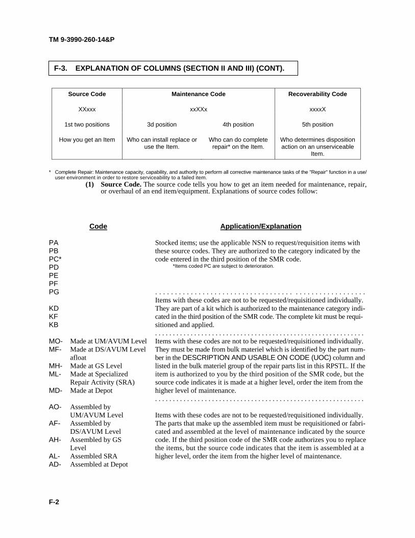
TM 9-3990-260-14&P
F-3. EXPLANATION OF COLUMNS (SECTION II AND III) (CONT).
Source Code Maintenance Code Recoverability Code
XXxxx xxXXx xxxxX
1st two positions 3d position 4th position 5th position
How you get an Item Who can install replace or use the Item.
Who can do complete repair* on the Item.
Who determines disposition action on an unserviceable
Item.
* Complete Repair: Maintenance capacity, capability, and authority to perform all corrective maintenance tasks of the "Repair" function in a use/ user environment in order to restore serviceability to a failed item.
(1) Source Code. The source code tells you how to get an item needed for maintenance, repair, or overhaul of an end item/equipment. Explanations of source codes follow:
Code Application/Explanation
PA Stocked items; use the applicable NSN to request/requisition items with PB these source codes. They are authorized to the category indicated by the PC* code entered in the third position of the SMR code. PD *Items coded PC are subject to deterioration.
PE PF PG . . . . . . . . . . . . . . . . . . . . . . . . . . . . . . . . . . . . . . . . . . . . . . . . . . . . . Items with these codes are not to be requested/requisitioned individually. KD They are part of a kit which is authorized to the maintenance category indi- KF cated in the third position of the SMR code. The complete kit must be requi- KB sitioned and applied. . . . . . . . . . . . . . . . . . . . . . . . . . . . . . . . . . . . . . . . . . . . . . . . . . . . . . . . . . . . MO- Made at UM/AVUM Level Items with these codes are not to be requested/requisitioned individually. MF- Made at DS/AVUM Level They must be made from bulk materiel which is identified by the part num- afloat ber in the DESCRIPTION AND USABLE ON CODE (UOC) column and MH- Made at GS Level listed in the bulk materiel group of the repair parts list in this RPSTL. If the ML- Made at Specialized item is authorized to you by the third position of the SMR code, but the Repair Activity (SRA) source code indicates it is made at a higher level, order the item from the MD- Made at Depot higher level of maintenance. . . . . . . . . . . . . . . . . . . . . . . . . . . . . . . . . . . . . . . . . . . . . . . . . . . . . . . . . . . . AO- Assembled by UM/AVUM Level Items with these codes are not to be requested/requisitioned individually. AF- Assembled by The parts that make up the assembled item must be requisitioned or fabri- DS/AVUM Level cated and assembled at the level of maintenance indicated by the source AH- Assembled by GS code. If the third position code of the SMR code authorizes you to replace Level the items, but the source code indicates that the item is assembled at a AL- Assembled SRA higher level, order the item from the higher level of maintenance. AD- Assembled at Depot
F-2

TM 9-3990-260-14&P
NOTE Cannibalization of controlled exchange, when authorized, may be used as a source of sup- ply for items with the following source codes, except for those source coded "XA".
Code Application/Explanation XA .......................DO NOT requisition an "XA"-coded item. Order its next higher assem-
bly. XB ........................In an "XB" item is not available from salvage, order it using the CAGE
and part number given. XC ........................Installation drawing, diagram, instruction sheet or field service drawing
that is identified by manufacturer's part number. XD .......................Item is not stocked. Order an "XD"-coded item through normal supply
channels using the CAGE and part number given, if no NSN is available. (2) Maintenance Code. Maintenance codes tell you the level(s) of maintenance authorized to
use and repair support items. The maintenance codes are entered in the third and fourth posi- tions of the SMR code as follows:
(a) The maintenance code entered in the third position tells you the lowest maintenance level authorized to remove, replace, and use an item. The maintenance code entered in the third position will indicate authorization to one of the following levels of mainte- nance.
Code Application/Explanation C .........................Operator or Crew Maintenance done within Unit Maintenance or aviation
unit maintenance.
O ..........................Unit Maintenance or aviation unit can remove, replace, and use the item.
F ..........................Direct Support Maintenance or aviation intermediate maintenance can remove, replace, and use the item.
H ..........................General Support Maintenance can remove, replace, and use the item. L ..........................Specialized Repair Activity (SRA) can remove, replace, and use the item. D ..........................Depot Maintenance can remove, replace, and use the item.
NOTE Some limited repair may be done on the item at a lower level of maintenance, if authorized by the Maintenance Allocation Chart (MAC) and SMR codes.
(b) The maintenance code entered in the fourth position tells whether or not the item is to be repaired and identifies the lowest maintenance level with the capability to do com- plete repair (i.e., perform all authorized "Repair" functions). The maintenance code in the fourth position will indicate authorization to one of the following levels of mainte- nance:
Code Application/Explanation O .......................... Unit Maintenance or aviation unit maintenance is the lowest level that can
do complete repair of the item.
F ........................... Direct Support Maintenance or aviation intermediate maintenance is the lowest level that can do complete repair of the item.
H .......................... General Support Maintenance is the lowest level that can do complete repair of the item.
F-3

TM 9-3990-260-14&P
F-3. EXPLANATION OF COLUMNS (SECTION II AND III) (CONT). Code Application/Explanation L. .......................... Specialized Repair Activity (SRA) is the lowest level that can do com-
plete repair of the item.
D .......................... Depot Maintenance is the lowest level that can do complete repair of the item.
Z .......................... Nonreparable. No repair is authorized.
B .......................... No repair is authorized. (No parts or special tools are authorized for the maintenance of a "B"-coded item.) However, the item may be recondi- tioned by adjusting, lubricating, etc., at the user level.
(3) Recoverability Code. Recoverability codes are assigned to items to indicate the disposition action on unserviceable items. The recoverability code is entered in the fifth position of the SMR code as follows:
Code Application/Explanation Z. .......................... Nonreparable item. When unserviceable, condemn and dispose of the
item at the level of maintenance shown in the third position of the SMR code.
O .......................... Reparable item. When uneconomically reparable, condemn and dispose of the item at Unit Maintenance or aviation unit maintenance.
F .......................... Reparable item. When uneconomically reparable, condemn and dispose of the item at Direct Support Maintenance or aviation intermediate main- tenance.
H .......................... Reparable item. When uneconomically reparable, condemn and dispose of the item at General Support Maintenance.
D .......................... Reparable item. When beyond lower level repair capability, return to Depot Maintenance. Condemnation and disposal of item not authorized below Depot Maintenance.
L ........................... Reparable item. Condemnation and disposal of item not authorized below Specialized Repair Activity (SRA).
A ........................... Item requires special handling or condemnation procedures because of specific reasons (e.g., precious metal content, high dollar value, critical material, or hazardous material). Refer to appropriate manuals/directives for specific instructions.
c. NSN -Column (3). Lists the National Stock Number assigned to an item. Use the NSNs for requisitions/requests.
d. CAGE -Column (4). The Commercial and Government Entity (CAGE) Code (C) is a five-digit alphanumeric code which is used to identify the manufacturer, distributor, or Government agency, etc., that sup- plies the item.
NOTE When you use an NSN to requisition an item, the item you receive may have a different part number from the part ordered.
F-4

TM 9-3990-260-14&P
F-5
e. PART NUMBER - Column (5). Indicates the primary number used by the manufacturer (indi-vidual, company, firm, corporation, or Government activity), which controls the design and characteristics of theitem by means of its engineering drawings, specifications, standards, and inspection requirements to identify anitem or range of items.
f. DESCRIPTION AND USABLE ON CODE (UOC) - Column (6). This column includes thefollowing information:
(1) The Federal item name and, when required, a minimum description to identify the item. (2) Physical security classification. Not applicable. (3) Items that are included in kits and sets are listed below the name of the kit or set. (4) Spare/repair part that make up an assembled item are listed immediately following the
assembled item line entry. (5) Part numbers for bulk materiels are referenced in this column in the line item entry for the
item to be manufactured/fabricated. (6) When the item is not used with all serial numbers of the same model, the effective serial
numbers are shown on the last line(s) of the description (before UOC). Not Applicable. (7) The Usable On Code, when applicable (see paragraph F-5, Special Information). (8) In the Special Tools List section, the Basis of Issue (BOI) appears as the last line(s) in the
entry for each special tool, special TMDE, and other special support equipment. When den-sity of equipment supported exceeds density spread indicated in the Basis of Issue, the totalauthorization is increased proportionately.
(9) The statement “END OF FIGURE” appears just below the last item description in Column 6for a given figure in both Section II and Section III.
g. QTY - Column (7). The QTY (quantity per figure) column indicates the quantity of the itemused in the breakout shown on the illustration/figure, which is prepared for a functional, subfunctional group, groupor an assembly. A “V” appearing in this column in lieu of a quantity indicates that the quantity is variable and thequantity may vary from application to application.
a. National Stock Number (NSN) Index.(1) STOCK NUMBER Column. This column lists the NSN by National Item Identification
Number (NIIN) sequence. The NIIN consists of the last nine digits of the NSN (i.e., NSN5305-01-674-1467). When using this column to locate an item, ignore the first four digits ofthe NSN. However, the complete NSN should be used when ordering items by stock num-ber.
(2) FIG. Column. This column lists the number of the figure where the item is identified/located. The figures are in numerical order in Section II and Section III.
(3) ITEM Column. The item number identifies the item associated with the figure listed in theadjacent FIG. column. This item is also identified by the NSN listed on the same line.
b. Part Number Index. Part Numbers in this index are listed by part number in ascending alphanu-meric sequence (i.e., vertical arrangement of letter and number combination which places the first letter or digit ofeach group in order A through Z, followed by the numbers 0 through 9 and each following letter or digit in like order).
F-4. EXPLANATION OF COLUMNS (SECTION IV).

TM 9-3990-260-14&P
F-6 Change 1
(1) CAGEC Column. The Commercial and Government Entity (CAGE) Code (C) is a five-digit alphanumeric code used to identify the manufacturer, distributor, or Governmentagency, etc., that supplies the item.
(2) PART NUMBER Column. Indicates the primary number used by the manufacturer (indi-vidual, firm, corporation, or Government activity) which controls the design andcharacteristics of the item by means of its engineering drawings, specifications, standards,and inspection requirements to identify an item or range of items.
(3) STOCK NUMBER Column. This column lists the NSN for the associated part numberand manufacturer identified in the PART NUMBER and CAGE columns to the left.
(4) FIG. Column. This column lists the number of the figure where the item is identified/located in Section II and Section III.
(5) ITEM Column. The item number assigned to the item as it appears in the figure refer-enced in the FIG. column.
a. Usable On Code. The Usable On Code appears in the lower left corner of the DESCRIP-TION column heading. Usable on codes are shown as “UOC” in the Description Column (justified left) on the lastline applicable item description/nomenclature. Uncoded items are applicable to all models. Identification of theusable on code in this publication is:
Code Used On
078 Container Roll-In/Out Platform (CROP) M3 and M3 CROP (S/N SC09001 and up)
079 Container Roll-In/Out Platform (CROP) M3A1
b. National Stock Numbers. The RPSTL incorporates a Commodity Command Standard Sys-tem (CCSS) program change that places the NSN back on the illustration parts list page. As a result, the Figure andItem Number to NSN Cross Reference Index has been deleted.
a. When National Stock Number or Part Number is Not Known: (1) First. Using the table of contents, determine the assembly group or subassembly group to
which the item belongs. This is necessary since figures are prepared for assembly groupsand subassembly groups, and listings are divided into the same groups.
(2) Second. Find the figure covering the assembly group or subassembly group to which theitem belongs.
(3) Third. Identify the item on the figure and use the Figure and Item Number Index to find theNSN.
F-4. EXPLANATION OF COLUMNS (SECTION IV) (CONT).
F-5. SPECIAL INFORMATION.
F-6. HOW TO LOCATE PARTS.

TM 9-3990-260-14&P
b. When National Stock Number or Part Number is Known:
(1) First. Using the National Stock Number Index or Part Number Index, find the pertinent NSN or part number. The NSN Index is in National Item Identification Number (NIIN) sequence [see paragraph F-4.a(1)]. The part numbers in the Part Number Index are listed in ascending alphanumeric sequence (see paragraph F-4.b). Both indexes cross-reference you to the illus- tration/figure and item number of the item you are looking for.
(2) Second. Turn to the figure and item number, verify that the item is the one you're looking for, then locate the item number in the repair parts list for the figure.
F.7. ABBREVIATIONS.
Abbreviations used in this appendix are listed in MIL-STD-12.
F-7


SECTION II TM 9-3990-260-14&P, C01
FIGURE 1a. M3 CROP
184
76
5*28
*29
2
31
20
7
8 *30
4
*31
*32
*34
*36*35
*33
*40
*39
*40
*41
*38
*37
NOTE: * INDICATES M3 CROP (S/N SC09001 AND UP) COMPONENTS


SECTION II TM 9-3990-260-14&P, C01
(1)
ITEM NO
(2)
SMR CODE
(3)
NSN
(4)
CAGEC
(5)
PART NUMBER
(6)
DESCRIPTION AND USABLE ONCODES(UOC)
(7)
QTY
GROUP 3301 REUSABLE SHIPPING CONTAINER
FIG. 1 M3 CROP
1 PAOZZ 5340-01-459-3150 0BJH4 12468684 STOWAGE LID ASSY .................................................UOC:078
2
*1 PAOZZ 5340-01-474-9152 0BJH4 12468633 RW STOWAGE LID ASSY FORWARD EARLY MODEL....UOC:078
1
*1 PAOZZ 5340-01-474-9150 0BJH4 12468636 RW STOWAGE LID ASSY REAR EARLY MODEL ...........UOC:078
1
*2 PAOZZ 3990-01-458-7313 0BJH4 12468790 REAR BLOCKER ASSY ..............................................UOC:078
1
*3 PAOZZ 3990-01-458-7313 0BJH4 12468790 REAR BLOCKER ASSY ..............................................UOC:078
1
*4 MOOZZ 49181 45501C-12 LANYARD ASSY MAKE FROM LANYARD .................KIT P/N: 97840A66 (39428) UOC:078
5
*5 PAOZZ 5315-01-465-3968 49181 45288 HITCHPIN CLIP...........................................................UOC:078
2
*6 PAOZZ 5315-01-459-3985 0BJH4 12468834 BAR, CAM ...................................................................UOC:078
2
*7 PAOZZ 2590-01-458-9179 0BJH4 12468830-1 BRACING MECHANISM LEFT-HAND SIDE ...............UOC:078
1
*7 PAOZZ 2590-01-458-9168 0BJH4 12468830-2 BRACING MECHANISM RIGHT-HAND SIDE...........UOC:078
1
*8 PAOZZ 3990-01-458-7323 0BJH4 12468785 CENTER BLOCKER ASSY .........................................UOC:078
1
*9 PAOZZ 5310-00-061-4650 96906 M45913/3-4CG8C NUT, SELF-LOCKING .................................................UOC:078
2
*10 PAOZZ 5310-00-823-8804 96906 MS27183-9 WASHER, FLAT...........................................................UOC:078
4
*11 PAOZZ 5340-01-474-9158 0BJH4 12468679-1 BRACKET, SPACER LEFT-HAND SIDE .....................UOC:078
1
*11 PAOZZ 5340-01-474-9144 0BJH4 12468679-2 BRACKET, SPACER RIGHT-HAND SIDE ...................UOC:078
1
*12 PAOZZ 5305-00-071-2241 66195 22492R1 BOLT, CAP, HEXAGON HE .........................................UOC:078
2
*13 PAOZZ 5305-01-474-9153 0BJH4 12468715 WASHER, REAR .........................................................UOC:078
2
*14 PAOZZ 5310-00-584-7890 96906 MS35338-57 WASHER, LOCK ........................................................UOC:078
4
15 PAOZZ 5310-01-465-0763 49181 36328 NUT, HEX ....................................................................UOC:078
4
*16 PAOZZ 5315-00-849-9854 80205 MS24665-498 KEY, COTTER .............................................................UOC:078
2
*17 PAOZZ 5315-01-461-3802 0BJH4 12468844 PIN, FRONT ................................................................UOC:078
3
*18 PAOZZ 5315-01-458-8034 49181 45284 HITCHPIN, CLIP..........................................................UOC:078
2
*19 PAOZZ 5315-01-469-6214 0BJH4 12468840 PIN, REAR...................................................................UOC:078
2
*20 PAOZZ 3830-01-456-8836 0BJH4 12468815 END STRUCTURE ASSY ...........................................UOC:078
1
*21 PAOZZ 5310-00-080-6004 96906 MS27183-14 WASHER, FLAT...........................................................UOC:078
4
*22 PAOZZ 5305-00-068-0510 80204 B1821BH038C100N SCREW, SOCKET HD CAP ........................................UOC:078
4
*23 PAOZZ 5340-01-474-9146 0BJH4 12468781 BUMPER .....................................................................UOC:078
2
*24 PAOZZ 3040-01-460-7209 0BJH4 12468747 ROLLER PIN ...............................................................UOC:078
2
25 PAOZZ 5315-01-459-3988 49181 64287 PIN, SPRING ...............................................................UOC:078
2
*26 PAOZZ 3910-01-477-3854 0BJH4 12468748 ROLLER 6", USED 2 TO REPLACE 12" ROLLER......UOC:078
4
1-1

SECTION II TM 9-3990-260-14&P, C01
*27 PAOZZ 5310-01-538-7789 49181 12468735 WASHER, FLAT...........................................................UOC:078
2
*28 PAOZZ 5340-00-185-6634 39428 3910T14 BOLT SNAP, SWIVEL. ................................................UOC:078
1
*29 PAOZZ 5305-00-068-0508 80204 B1821BH025C075N BOLT, HEX HEAD, 1/4-20 X 3/4”.................................UOC:078
1
*30 PAOZZ 5310-00-088-1251 81349 M45913/1-4CG5C NUT, SELF-LOCKING, HEXAGON..............................UOC:078
1
*31 PAOZZ 0BJH4 1246812 COVER PLATE, SIDE BLOCKER. ..............................UOC:078
1
*32 PAOZZ 9535-01-529-1098 19207 12468700 PANEL, FRONT DECK................................................UOC:078
1
*33 PAOZZ 9535-01-529-1110 19207 12468701 PANEL, MID DECK. ....................................................UOC:078
2
*34 PAOZZ 9535-01-529-6491 19207 12468705 PANEL, LEFT SIDE DECK..........................................UOC:078
1
*35 PAOZZ 9535-01-529-1107 19207 12468702 PANEL, RIGHT SIDE DECK. ......................................UOC:078
1
*36 PAOZZ 9905-01-533-1810 19207 12468704 PANEL, REAR DECK. .................................................UOC:078
1
*37 PAOZZ 5340-01-529-7916 0BJH4 12468616-1 INTERFACE BRACKET ASSY (LEFT SIDE). .............UOC:078
1
*37 PAOZZ 5340-01-529-6835 0BJH4 12468616-2 INTERFACE BRACKET ASSY (RIGHT SIDE)............UOC:078
1
*38 PAOZZ 0BJH4 12468754 MARKER SPRING.......................................................UOC:078
2
*39 PAOZZ 49181 37574 NUT..............................................................................UOC:078
2
*40 PAOZZ 49181 33181 WASHER.....................................................................UOC:078
4
*41 PAOZZ 49181 13057 BOLT............................................................................UOC:078
2
END OF FIGURE
(1)
ITEM NO
(2)
SMR CODE
(3)
NSN
(4)
CAGEC
(5)
PART NUMBER
(6)
DESCRIPTION AND USABLE ONCODES(UOC)
(7)
QTY
1-2


SECTION II TM 9-3990-260-14&P
FIGURE 2. REAR BLOCKER ASSEMBLY AND STOWAGE DOOR COMPONENTS
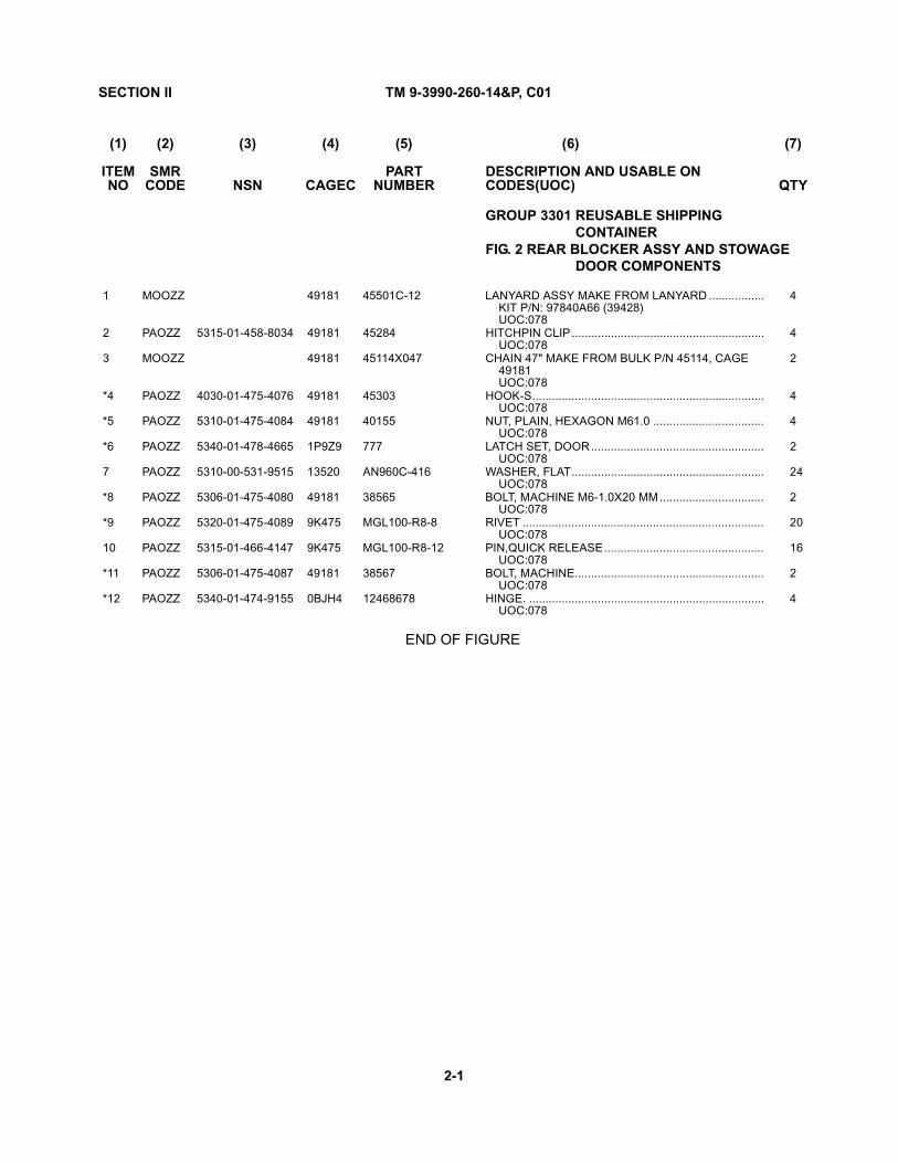
SECTION II TM 9-3990-260-14&P, C01
(1)
ITEM NO
(2)
SMR CODE
(3)
NSN
(4)
CAGEC
(5)
PART NUMBER
(6)
DESCRIPTION AND USABLE ONCODES(UOC)
(7)
QTY
GROUP 3301 REUSABLE SHIPPING CONTAINER
FIG. 2 REAR BLOCKER ASSY AND STOWAGE DOOR COMPONENTS
1 MOOZZ 49181 45501C-12 LANYARD ASSY MAKE FROM LANYARD .................KIT P/N: 97840A66 (39428)UOC:078
4
2 PAOZZ 5315-01-458-8034 49181 45284 HITCHPIN CLIP...........................................................UOC:078
4
3 MOOZZ 49181 45114X047 CHAIN 47" MAKE FROM BULK P/N 45114, CAGE 49181UOC:078
2
*4 PAOZZ 4030-01-475-4076 49181 45303 HOOK-S.......................................................................UOC:078
4
*5 PAOZZ 5310-01-475-4084 49181 40155 NUT, PLAIN, HEXAGON M61.0 ..................................UOC:078
4
*6 PAOZZ 5340-01-478-4665 1P9Z9 777 LATCH SET, DOOR.....................................................UOC:078
2
7 PAOZZ 5310-00-531-9515 13520 AN960C-416 WASHER, FLAT...........................................................UOC:078
24
*8 PAOZZ 5306-01-475-4080 49181 38565 BOLT, MACHINE M6-1.0X20 MM................................UOC:078
2
*9 PAOZZ 5320-01-475-4089 9K475 MGL100-R8-8 RIVET ..........................................................................UOC:078
20
10 PAOZZ 5315-01-466-4147 9K475 MGL100-R8-12 PIN,QUICK RELEASE.................................................UOC:078
16
*11 PAOZZ 5306-01-475-4087 49181 38567 BOLT, MACHINE..........................................................UOC:078
2
*12 PAOZZ 5340-01-474-9155 0BJH4 12468678 HINGE. ........................................................................UOC:078
4
END OF FIGURE
2-1

SECTION II TM 9-3990-260-14&P
FIGURE 3. CENTER BLOCKER ASSEMBLY

SECTION II TM 9-3990-260-14&P, C01
(1)
ITEM NO
(2)
SMR CODE
(3)
NSN
(4)
CAGEC
(5)
PART NUMBER
(6)
DESCRIPTION AND USABLE ONCODES(UOC)
(7)
QTY
GROUP 3301REUSABLE SHIPPING CONTAINER
FIG. 3 CENTER BLOCKER ASSY
1 MOOZZ 49181 45501C-12 LANYARD ASSY MAKE FROM LANYARD .................KIT P/N: 97840A66 (39428)UOC:078
2
*2 PAOZZ 5340-00-185-6634 39428 3910T14 BOLT SNAP, SWIVEL..................................................UOC:078
2
END OF FIGURE
3-1
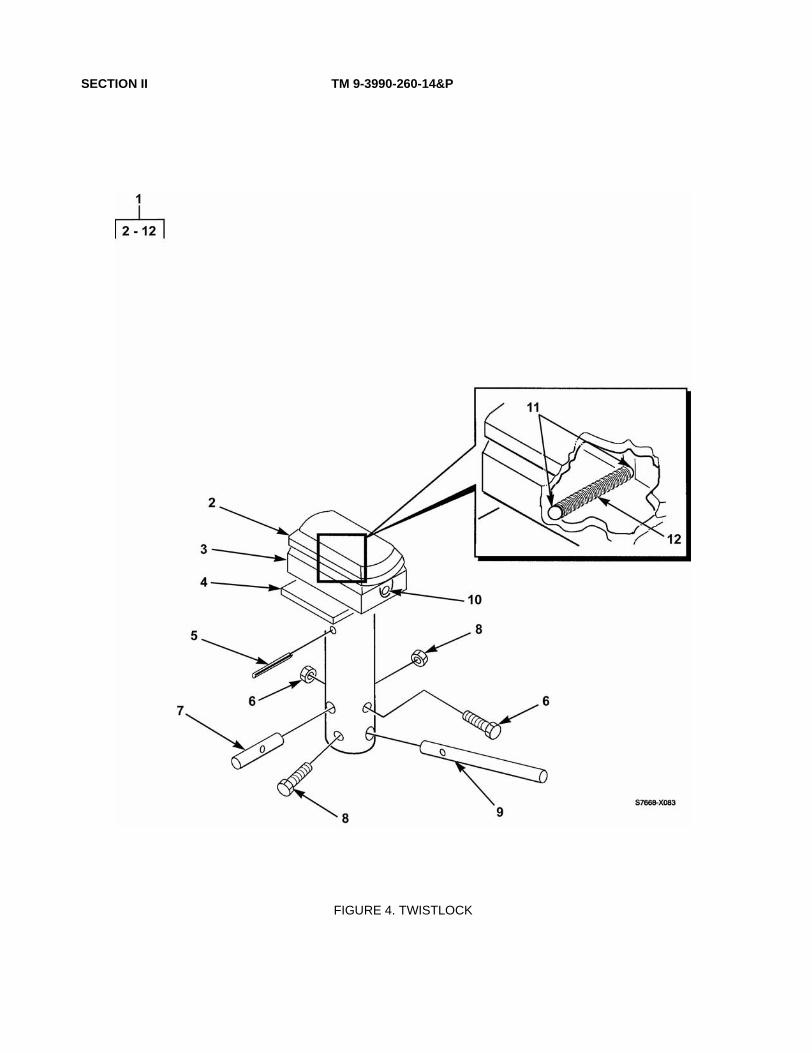
SECTION II TM 9-3990-260-14&P
FIGURE 4. TWISTLOCK

SECTION II TM 9-3990-260-14&P, C01
(1)
ITEM NO
(2)
SMR CODE
(3)
NSN
(4)
CAGEC
(5)
PART NUMBER
(6)
DESCRIPTION AND USABLE ONCODES(UOC)
(7)
QTY
GROUP 3301REUSABLE SHIPPING CONTAINER
FIG. 4 TWISTLOCK
*1 PAOOO 5340-01-465-6233 0BJH4 12468751-1 TWISTLOCK ASSY, LH ...............................................UOC:078
2
*1 PAOOO 5340-01-465-5977 0BJH4 12468751-2 TWISTLOCK ASSY, RH...............................................UOC:078
2
2 XDOZZ OSW64 BU1159-2 •PIN..............................................................................UOC:078
1
3 XDOZZ OSW64 BU1159-3 •SHEARBLOCK ...........................................................UOC:078
1
4 XDOZZ OSW64 BU1159-5 •PLATE, GUIDE ...........................................................UOC:078
1
5 XDOZZ OSW64 BU1159-7 •PIN, ROLL ..................................................................UOC:078
1
6 XDOZZ OSW64 BU1159-12 •SHEAR PIN BOLT ......................................................UOC:078
1
7 XDOZZ OSW64 BU1159-6 •PIN, SHEAR ...............................................................UOC:078
1
8 XDOZZ OSW64 BU1159-11 •HANDLE, BOLT..........................................................UOC:078
1
9 XDOZZ OSW64 BU1159-4 •HANDLE.....................................................................UOC:078
1
10 XDOZZ OSW64 BU1159-10 •FITTING, GREASE .....................................................UOC:078
1
11 XDOZZ OSW64 BU1159-8 •DETENT BALL ...........................................................UOC:078
2
12 XDOZZ OSW64 BU1159-9 •SPRING, DETENT......................................................UOC:078
1
END OF FIGURE
4-1

SECTION II TM 9-3990-260-14&P
FIGURE 5. DATA PLATES

SECTION II TM 9-3990-260-14&P, C01
(1)
ITEM NO
(2)
SMR CODE
(3)
NSN
(4)
CAGEC
(5)
PART NUMBER
(6)
DESCRIPTION AND USABLE ONCODES(UOC)
(7)
QTY
GROUP 3301 REUSABLE SHIPPING CONTAINER
FIG. 5 DATA PLATES
*1 PFOZZ 9905-01-461-1809 0BJH4 12468762 PLATE, IDENTIFICATION ...........................................UOC:078
1
*2 PFOZZ 9905-01-459-7872 0BJH4 12468763 PLATE, SHIPPING.......................................................UOC:078
1
END OF FIGURE
5-1

SECTION II TM 9-3990-260-14&P
FIGURE 6. BASE ASSEMBLY AND REAR FRAME COMPONENTS, M3A1

SECTION II TM 9-3990-260-14&P, C01
(1)
ITEM NO
(2)
SMR CODE
(3)
NSN
(4)
CAGEC
(5)
PART NUMBER
(6)
DESCRIPTION AND USABLE ONCODES(UOC)
(7)
QTY
GROUP 3301 REUSABLE SHIPPING CONTAINER
FIG. 6 BASE ASSEMBLY AND REAR FRAME COMPONENTS, M3A1
1 XDOFF 07GE7 3-33001 BASE ASSEMBLY .......................................................UOC:079
1
*2 PAOZZ 9540-01-474-9305 07GE7 1-33086 PLATE, WEAR SIDE FRONT ......................................UOC:079
2
*2 PAOZZ 9540-01-474-9601 07GE7 1-33085 PLATE, WEAR SIDE CENTER....................................UOC:079
2
*2 PAOZZ 9540-01-474-9603 07GE7 1-33084 PLATE, WEAR SIDE REAR.........................................UOC:079
2
3 PAOZZ 5315-01-466-4147 9K475 MGL100-R8-12 PIN, QUICK RELEASE................................................UOC:079
52
*4 PFOZZ 5340-01-474-9307 07GE7 2-33106 PLATE, RESTRAINT LH..............................................UOC:079
1
*4 PFOZZ 9535-01-474-9621 07GE7 2-33109 PLATE, RESTRAINT RH .............................................UOC:079
1
*4 PFOZZ 5340-01-474-8502 07GE7 2-33107 PLATE, RESTRAINT CENTER LOCATION ................UOC:079
1
5 PAOZZ 5315-00-297-2444 96906 MS24665-623 PIN, COTTER, SPLIT ..................................................UOC:079
6
6 PFOZZ 5315-01-466-4712 07GE7 1-33122 PIN,STRAIGHT CENTER PLATE................................UOC:079
1
6 PFOZZ 5315-01-466-4049 07GE7 1-33123 PIN,STRAIGHT LEFT SIDE ........................................UOC:079
1
6 PFOZZ 5315-01-466-4102 07GE7 1-33124 PIN,STRAIGHT RIGHT SIDE ......................................UOC:079
1
7 PAOZZ 5315-01-466-4048 07GE7 1-33121 PIN, HAIR ....................................................................UOC:079
3
8 MOOZZ 07GE7 2-33105B-12 LANYARD ASSY MAKE FROM LANYARD KITP/N: 97840A66 (39428) ..............................................
UOC:079
3
*9 PAOZZ 3040-01-478-1204 07GE7 2-33401 SHAFT, AXLE ..............................................................UOC:079
2
10 PAOZZ 5315-00-849-9854 96906 MS24665-498 PIN, COTTER ..............................................................UOC:079
2
11 PAOZZ 5310-00-950-1309 96906 MS28183-31 WASHER, FLAT...........................................................UOC:079
10
*12 PAOZZ 3990-01-478-2117 07GE7 1-33401 WHEEL, ROLLER........................................................UOC:079
6
*13 PAOZZ 5305-01-474-8504 8V863 50C275S0C0 SCREW, CAP, HEXAGON H .......................................UOC:079
4
*14 PAOZZ 5340-01-478-2120 07GE7 1-33409 BUMPER RH ...............................................................UOC:079
1
14 PAOZZ 07GE7 1-33417 BUMPER LH................................................................UOC:079
1
15 PAOZZ 5310-00-809-5998 96906 MS27183-18 WASHER, FLAT...........................................................UOC:079
4
16 PAOZZ 5310-00-584-5272 96906 MS35338-48 WASHER, LOCKING ...................................................UOC:079
4
17 PAOZZ 5310-00-768-0318 96906 MS51967-14 NUT, PLAIN, HEXAGON .............................................UOC:079
4
END OF FIGURE
6-1
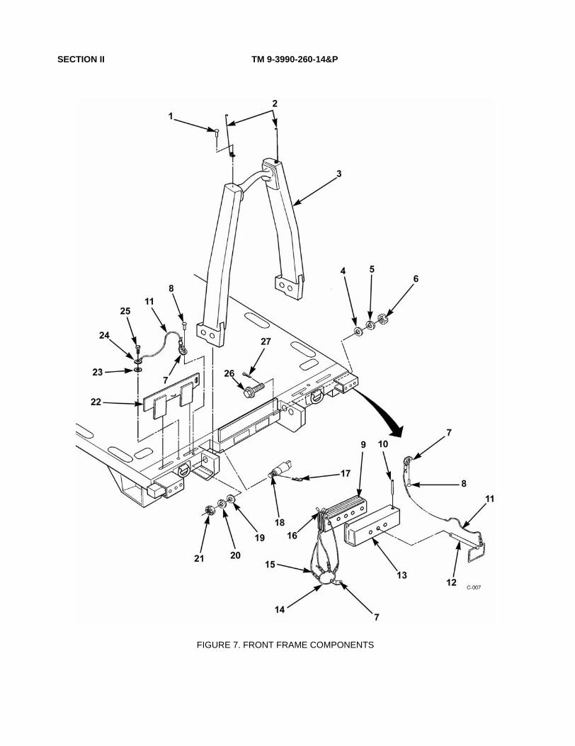
SECTION II TM 9-3990-260-14&P
FIGURE 7. FRONT FRAME COMPONENTS

SECTION II TM 9-3990-260-14&P, C01
(1)
ITEM NO
(2)
SMR CODE
(3)
NSN
(4)
CAGEC
(5)
PART NUMBER
(6)
DESCRIPTION AND USABLE ONCODES(UOC)
(7)
QTY
GROUP 3301 REUSABLE SHIPPING CONTAINER
FIG. 7 FRONT FRAME COMPONENTS, M3A1
*1 PAOZZ 5305-01-478-3584 07GE7 1-33312 SCREW, SOCKET HEAD............................................UOC:079
2
2 PAOZZ 5365-01-466-3848 07GE7 1-33302 GUIDE, HOOK-UP.......................................................UOC:079
2
3 XDOZZ 07GE7 2-33305 A-FRAME ASSEMBLY.................................................UOC:079
1
4 PAOZZ 5310-00-982-6568 96906 MS27183-33 WASHER, FLAT...........................................................UOC:079
2
5 PAOZZ 5310-01-466-3933 07GE7 1-33242 WASHER, LOCKING ...................................................UOC:079
2
6 PAOZZ 5310-00-470-9340 96906 MS35692-97 NUT, PLAIN, SLOTTED...............................................UOC:079
2
7 PFOZZ 5340-01-466-3910 07GE7 1-33253 BRACKET, HOLDERPART OF KIT P/N: 97840A66 (39428) .......................
UOC:079
4
8 PFOZZ 5315-01-466-4174 9K475 MGLP-R8-10 RIVET, STUD...............................................................UOC:079
6
*9 PAOZZ 5365-01-478-3507 07GE7 1-33275 PLATE, SHIM...............................................................UOC:079
8
10 PAOZZ 07GE7 11-3249 PIN,STOPPER.............................................................UOC:079
2
11 MOOZZ 07GE7 11-3254A-16 LANYARD ASSY MAKE FROM LANYARDKIT P/N: 97840A66 (39428) .......................................
UOC:079
4
12 PAOZZ 5315-01-466-4108 07GE7 1-33222 PIN,RETAINING...........................................................UOC:079
2
*13 PAOZZ 5340-01-484-6575 07GE7 2-33209 PIN, LOCK CONTAINER INCLUDES PIN, STOPPERUOC:079
2
14 XDOZZ 07GE7 1-33264 RING, ROPE ................................................................UOC:079
2
15 MOOZZ 07GE7 1-33262A-009 LANYARD ASSY MAKE FROM LANYARDKIT P/N: 97840A66 (39428) .......................................
UOC:079
8
16 KFOZZ 07GE7 1-33261 SEIZING BAND IIPART OF KIT P/N: 97840A66 (39428) .......................
UOC:079
8
*17 PAFZZ 5315-01-474-9596 07GE7 1-33263 PIN, HAIR ....................................................................UOC:079
2
*18 PAOZZ 5315-01-474-9200 07GE7 1-33257 PIN, SPECIAL LOCKING ............................................UOC:079
2
19 PFOZZ 5310-01-466-3923 07GE7 1-33233 WASHER, FLAT...........................................................UOC:079
2
20 PAOZZ 5310-01-466-3882 07GE7 1-33236 WASHER, LOCKING ...................................................UOC:079
2
21 PAOZZ 5310-00-842-7616 96906 MS35692-105 NUT, PLAIN, SLOTTED...............................................UOC:079
2
22 PAOZZ 5340-01-466-3884 07GE7 2-33202 PLATE, RESTRAINT ...................................................UOC:079
2
*22 PAOZZ 5340-01-474-9594 07GE7 2-33211 PLATE, RESTRAINT ...................................................UOC:079
2
23 XDOZZ 07GE7 1-33244 WASHER, RETAINING................................................UOC:079
2
24 PFOZZ 5310-01-466-3183 07GE7 1-33241 WASHER, SPECIAL ....................................................UOC:079
2
25 PAOZZ 5305-00-071-2069 80204 B1821BH050C150N SCREW, CAP, HEXAGON H .......................................UOC:079
2
*26 PAOZZ 5306-01-474-9204 07GE7 1-33258 BOLT, SPECIAL...........................................................UOC:079
2
27 PAOZZ 5315-00-013-7303 96906 MS24665-626 PIN, COTTER SLIT .....................................................UOC:079
2
END OF FIGURE
7-1

SECTION II TM 9-3990-260-14&P
FIGURE 8. STORAGE DOORS AND TWISTLOCK ASSEMBLY, M3A1
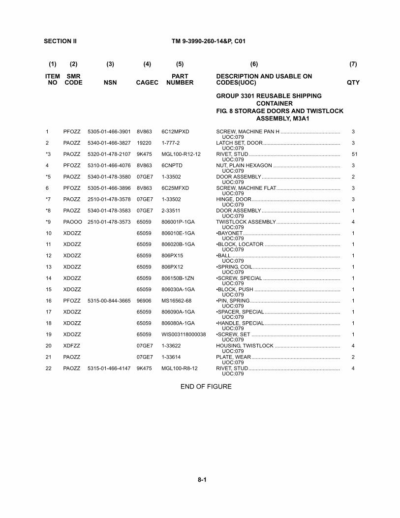
SECTION II TM 9-3990-260-14&P, C01
(1)
ITEM NO
(2)
SMR CODE
(3)
NSN
(4)
CAGEC
(5)
PART NUMBER
(6)
DESCRIPTION AND USABLE ONCODES(UOC)
(7)
QTY
GROUP 3301 REUSABLE SHIPPING CONTAINER
FIG. 8 STORAGE DOORS AND TWISTLOCK ASSEMBLY, M3A1
1 PFOZZ 5305-01-466-3901 8V863 6C12MPXD SCREW, MACHINE PAN H .........................................UOC:079
3
2 PAOZZ 5340-01-466-3827 19220 1-777-2 LATCH SET, DOOR.....................................................UOC:079
3
*3 PAOZZ 5320-01-478-2107 9K475 MGL100-R12-12 RIVET, STUD...............................................................UOC:079
51
4 PFOZZ 5310-01-466-4076 8V863 6CNPTD NUT, PLAIN HEXAGON ..............................................UOC:079
3
*5 PAOZZ 5340-01-478-3580 07GE7 1-33502 DOOR ASSEMBLY......................................................UOC:079
2
6 PFOZZ 5305-01-466-3896 8V863 6C25MFXD SCREW, MACHINE FLAT............................................UOC:079
3
*7 PAOZZ 2510-01-478-3578 07GE7 1-33502 HINGE, DOOR.............................................................UOC:079
3
*8 PAOZZ 5340-01-478-3583 07GE7 2-33511 DOOR ASSEMBLY......................................................UOC:079
1
*9 PAOOO 2510-01-478-3573 65059 806001P-1GA TWISTLOCK ASSEMBLY............................................UOC:079
4
10 XDOZZ 65059 806010E-1GA •BAYONET...................................................................UOC:079
1
11 XDOZZ 65059 806020B-1GA •BLOCK, LOCATOR ....................................................UOC:079
1
12 XDOZZ 65059 806PX15 •BALL...........................................................................UOC:079
1
13 XDOZZ 65059 806PX12 •SPRING, COIL............................................................UOC:079
1
14 XDOZZ 65059 806150B-1ZN •SCREW, SPECIAL .....................................................UOC:079
1
15 XDOZZ 65059 806030A-1GA •BLOCK, PUSH ...........................................................UOC:079
1
16 PFOZZ 5315-00-844-3665 96906 MS16562-68 •PIN, SPRING..............................................................UOC:079
1
17 XDOZZ 65059 806090A-1GA •SPACER, SPECIAL....................................................UOC:079
1
18 XDOZZ 65059 806080A-1GA •HANDLE, SPECIAL....................................................UOC:079
1
19 XDOZZ 65059 WIS003118000038 •SCREW, SET .............................................................UOC:079
1
20 XDFZZ 07GE7 1-33622 HOUSING, TWISTLOCK .............................................UOC:079
4
21 PAOZZ 07GE7 1-33614 PLATE, WEAR.............................................................UOC:079
2
22 PAOZZ 5315-01-466-4147 9K475 MGL100-R8-12 RIVET, STUD...............................................................UOC:079
4
END OF FIGURE
8-1

SECTION II TM 9-3990-260-14&P
FIGURE 9. DATA PLATES, M3A1
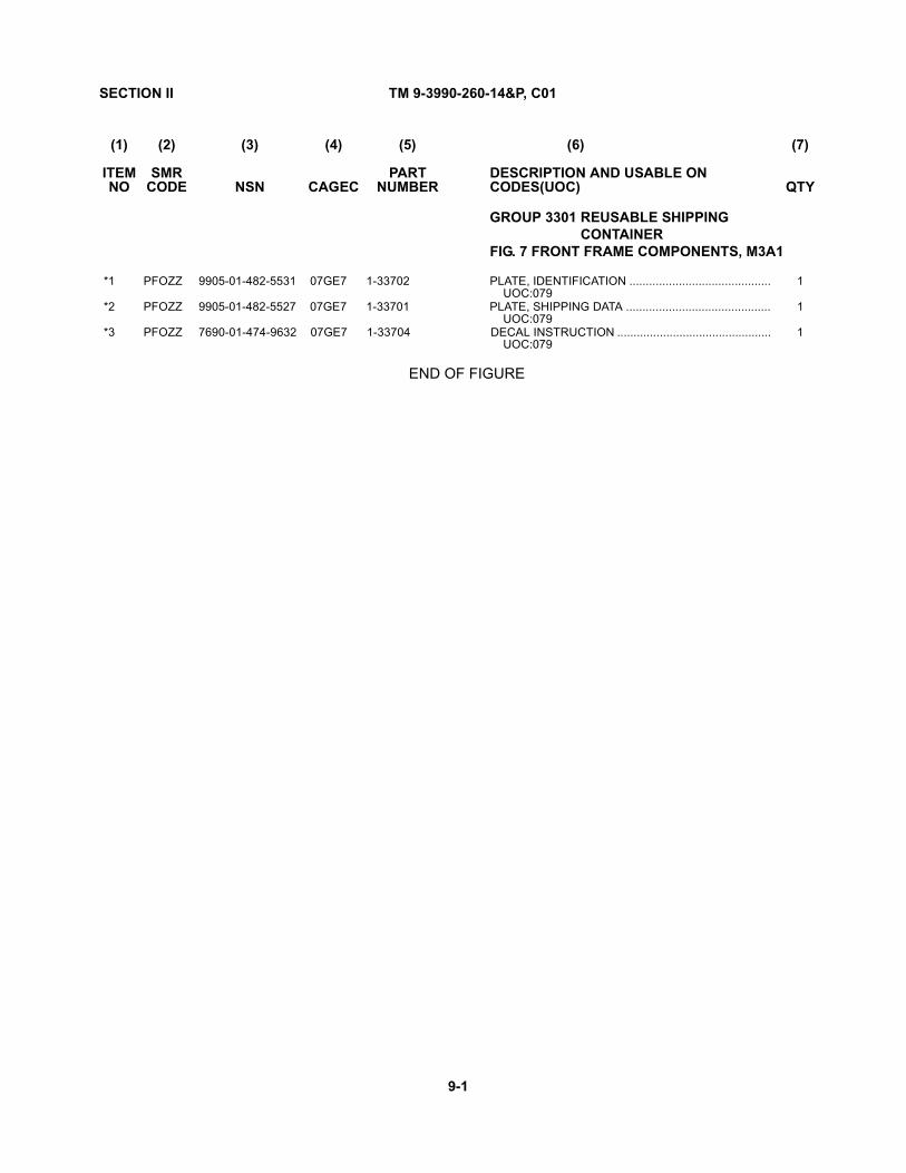
SECTION II TM 9-3990-260-14&P, C01
(1)
ITEM NO
(2)
SMR CODE
(3)
NSN
(4)
CAGEC
(5)
PART NUMBER
(6)
DESCRIPTION AND USABLE ONCODES(UOC)
(7)
QTY
GROUP 3301 REUSABLE SHIPPING CONTAINER
FIG. 7 FRONT FRAME COMPONENTS, M3A1
*1 PFOZZ 9905-01-482-5531 07GE7 1-33702 PLATE, IDENTIFICATION ...........................................UOC:079
1
*2 PFOZZ 9905-01-482-5527 07GE7 1-33701 PLATE, SHIPPING DATA ............................................UOC:079
1
*3 PFOZZ 7690-01-474-9632 07GE7 1-33704 DECAL INSTRUCTION ...............................................UOC:079
1
END OF FIGURE
9-1


SECTION II TM 9-3990-260-14&P
(1) (2) (3) (4) (5) (6) (7) ITEM SMR PART DESCRIPTION AND USABLE ON QTY NO CODE NSN CAGEC NUMBER CODES(UOC)
GROUP 94 REPAIR KITS GROUP 9401 REPAIR KITS
FIG. KITS, M3A1
1 PAOZZ 4010-01-454-8588 39428 97840A66 LANYARD KIT ......................................................................V
END OF FIGURE
KITS-1


SECTION II TM 9-3990-260-14&P, C01
(1)
ITEM NO
(2)
SMR CODE
(3)
NSN
(4)
CAGEC
(5)
PART NUMBER
(6)
DESCRIPTION AND USABLE ONCODES(UOC)
(7)
QTY
GROUP 3301 REUSABLE SHIPPING CONTAINER
FIG. 7 FRONT FRAME COMPONENTS, M3A1
*1 PAOZZ 5340-01-475-4081 49181 45114 CHAIN, #8 SASH, ZINC ..............................................UOC:078
V
END OF FIGURE
BULK-1


SECTION IV TM 9-3990-260-14&P
CROSS REFERENCE INDEXES
NATIONAL STOCK NUMBER INDEX
STOCK NUMBER FIGURE ITEM STOCK NUMBER
FIGURE ITEM
5315-00-013-7303 7 27 5305-00-071-2069 7 25 5305-00-071-2075 6 13 5315-00-297-2444 6 5 5310-00-470-9340 7 6 5310-00-531-9515 2 7 5310-00-584-5272 6 16 5310-00-768-0318 6 17 5310-00-809-5998 6 15 5310-00-842-7616 7 21 5315-00-844-3665 8 16 5315-00-849-9854 6 10 5310-00-950-1309 6 11 5310-00-982-6568 7 4 4010-01-454-8588 KITS 1 3830-01-456-8836 1 20 3990-01-458-7313 1 2 3990-01-458-7320 1 3 3990-01-458-7323 1 8 5315-01-458-8034 1 5 2590-01-458-9168 1 7 2590-01-458-9179 1 7 3130-01-459-0115 1 27 5340-01-459-3150 1 1 5315-01-459-3985 1 6 5315-01-459-3988 1 25 9905-01-459-7872 5 2 3040-01-460-7290 1 24 9905-01-461-1809 5 1 5315-01-461-3802 1 17 5310-01-465-0763 1 15 5315-01-465-3968 1 18 5340-01-466-3827 8 2 5310-01-466-3882 7 20 5340-01-466-3884 7 22 5305-01-466-3896 8 6 5305-01-466-3901 8 1 5340-01-466-3910 7 7 5310-01-466-3923 7 19 5310-01-466-3933 7 5 5315-01-466-4048 6 7 5315-01-466-4049 6 6 5310-01-466-4076 8 4 5315-01-466-4102 6 6 5315-01-466-4108 7 12 5315-01-466-4147 2 10 5315-01-466-4147 8 22 5315-01-466-4712 6 6
I-1

SECTION IV TM 9-3990-260-14&P
CROSS REFERENCE INDEXES
PART NUMBER INDEX
FSCM PART NUMBER STOCK NUMBER FIGURE NO ITEM NO
3520 AN960C-416 5310-00-531-9515 2 7 80204 B1821BH050C150N 5305-00-071-2069 7 25 OSW64 BU1159-10 4 10 OSW64 BU1159-11 4 8 OSW64 BU1159-12 4 6 OSW64 BU 1159-2 4 2 OSW64 BU 1159-3 4 3 OSW64 BU1159-4 4 9 OSW64 BU 1159-5 4 4 OSW64 BU 1159-6 4 7 OSW64 BU1159-7 4 5 OSW64 BU1159-8 4 11 OSW64 BU1159-9 4 12 49181 CP4320064AL0000 1 16 9K475 MGLP-R8-10 5315-01-466-4174 7 8 9K475 MGL100-R12-12 8 3 9K475 MGL100-R8-8 2 9 9K475 MGL100-R8-12 5315-01-466-4147 2 10 9K475 MGL100-R8-12 5315-01-466-4147 6 3 9K475 MGL 100-R8-12 5315-01-466-4147 8 22 96906 MS16562-68 5315-00-844-3665 8 16 96906 MS24665-623 5315-00-297-2444 6 5 96906 MS24665-498 5315-00-849-9854 6 10 96906 MS24665-626 5315-00-013-7303 7 27 96906 MS27183-18 5310-00-809-5998 6 15 96906 MS27183-31 5310-00-950-1309 6 11 96906 MS27183-33 5310-00-982-6568 7 4 96906 MS35338-48 5310-00-584-5272 6 16 96906 MS35692-105 5310-00-842-7616 7 21 96906 MS35692-97 5310-00-470-9340 7 6 96906 MS51967-14 5310-00-768-0318 6 17 65059 WISO03118000038 8 19 19207 12467848 1 26 19207 12468633RW 1 1 19207 12468636 RW 1 1 19207 12468678 2 12 19207 12468679-1 1 11 19207 12468679-2 1 11 19207 12468684 5340-01-459-3150 1 1 19207 12468715 1 13 19207 12468746 1 24 19207 12468751-1 4 1 19207 12468751-2 4 1 19207 12468762 9905-01-461-1809 5 1 19207 12468763 9905-01-459-7872 5 2 19207 12468781 1 23 19207 12468785 3990-01-458-7323 1 8 19207 12468790-1 3990-01-458-7320 1 3 19207 12468790-2 3990-01-458-7313 1 2 19207 12468815 3830-01-456-8836 1 20 19207 12468830-1 2590-01-458-9179 1 7 19207 12468830-2 2590-01-458-9168 1 7 19207 12468834 5315-01-459-3985 1 6 19207 12468840 1 19
I-2
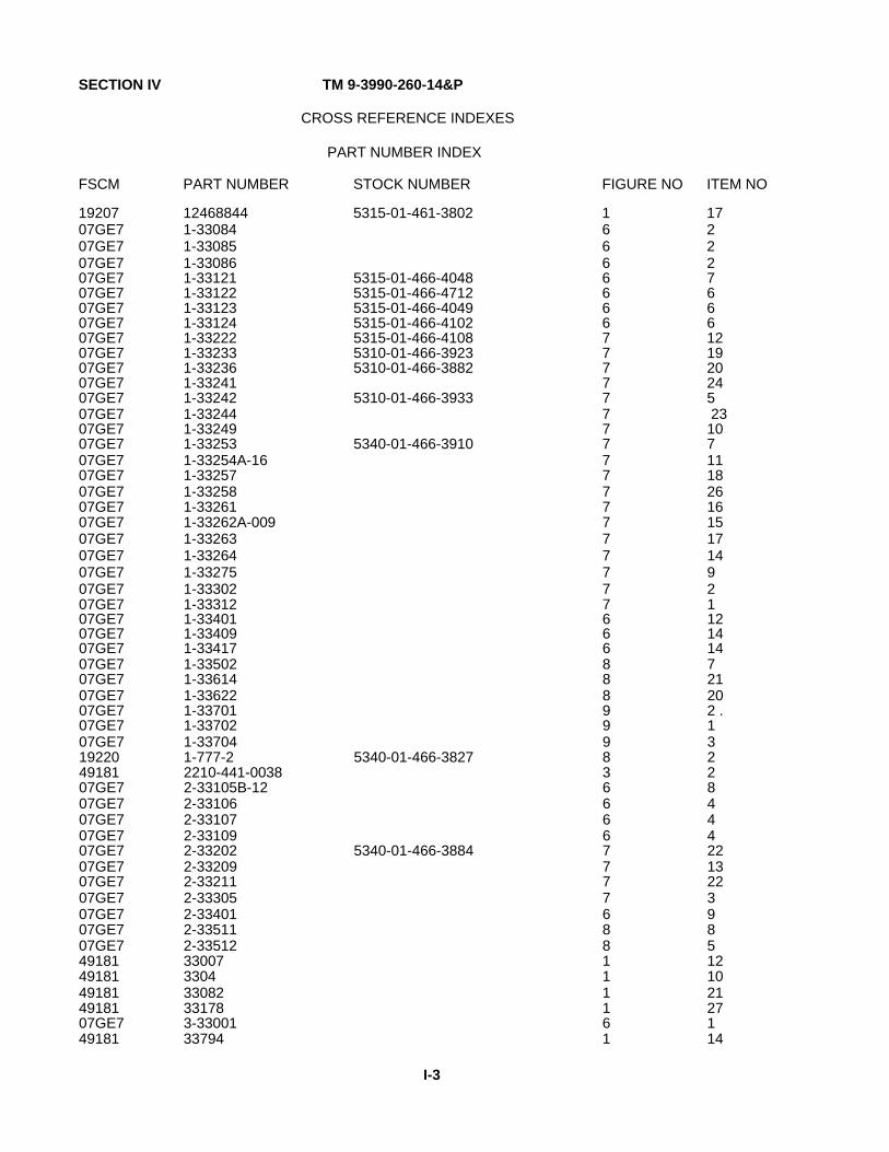
SECTION IV TM 9-3990-260-14&P
CROSS REFERENCE INDEXES
PART NUMBER INDEX
FSCM PART NUMBER STOCK NUMBER FIGURE NO ITEM NO
19207 12468844 5315-01-461-3802 1 17 07GE7 1-33084 6 2 07GE7 1-33085 6 2 07GE7 1-33086 6 2 07GE7 1-33121 5315-01-466-4048 6 7 07GE7 1-33122 5315-01-466-4712 6 6 07GE7 1-33123 5315-01-466-4049 6 6 07GE7 1-33124 5315-01-466-4102 6 6 07GE7 1-33222 5315-01-466-4108 7 12 07GE7 1-33233 5310-01-466-3923 7 19 07GE7 1-33236 5310-01-466-3882 7 20 07GE7 1-33241 7 24 07GE7 1-33242 5310-01-466-3933 7 5 07GE7 1-33244 7 23 07GE7 1-33249 7 10 07GE7 1-33253 5340-01-466-3910 7 7 07GE7 1-33254A-16 7 11 07GE7 1-33257 7 18 07GE7 1-33258 7 26 07GE7 1-33261 7 16 07GE7 1-33262A-009 7 15 07GE7 1-33263 7 17 07GE7 1-33264 7 14 07GE7 1-33275 7 9 07GE7 1-33302 7 2 07GE7 1-33312 7 1 07GE7 1-33401 6 12 07GE7 1-33409 6 14 07GE7 1-33417 6 14 07GE7 1-33502 8 7 07GE7 1-33614 8 21 07GE7 1-33622 8 20 07GE7 1-33701 9 2 . 07GE7 1-33702 9 1 07GE7 1-33704 9 3 19220 1-777-2 5340-01-466-3827 8 2 49181 2210-441-0038 3 2 07GE7 2-33105B-12 6 8 07GE7 2-33106 6 4 07GE7 2-33107 6 4 07GE7 2-33109 6 4 07GE7 2-33202 5340-01-466-3884 7 22 07GE7 2-33209 7 13 07GE7 2-33211 7 22 07GE7 2-33305 7 3 07GE7 2-33401 6 9 07GE7 2-33511 8 8 07GE7 2-33512 8 5 49181 33007 1 12 49181 3304 1 10 49181 33082 1 21 49181 33178 1 27 07GE7 3-33001 6 1 49181 33794 1 14
I-3

SECTION IV TM 9-3990-260-14&P
CROSS REFERENCE INDEXES
PART NUMBER INDEX
FSCM PART NUMBER STOCK NUMBER FIGURE NO ITEM NO
49181 36328 1 15 49181 37018 1 9 49181 38565 2 8 49181 38567 2 11 49181 40155 2 5 49181 45114 BULK 1 49181 45114X047 2 3 49181 45284 5315-01-458-8034 1 5 2 2 49181 45288 1 18 49181 45303 2 4 49181 45501C-12 1 4 2 1 3 1 8V863 50C275S0CD 6 13 8V863 6CNPTD 5310-01-466-4076 8 4 8V863 6C12MPXD 5305-01-466-3901 8 1 8V863 6C25MFXD 5305-01-466-3896 8 6 49181 64287 5315-01-459-3988 1 25 90455 777 2 6 65059 806PX12 8 13 65059 806PX15 8 12 55059 806001P-1GA 8 9 65059 806010E-1GA 8 10 65059 806020B-1GA 8 11 65059 806030A-1GA 8 15 65059 806080A-1GA 8 18 65059 806090A-1GA 8 17 65059 806150B-1ZN 8 14 49181 93305 1 22 39428 97840A66 4010-01-454-8588 KITS 1
I-4

TM 9-3990-260-14&P
APPENDIX G
ILLUSTRATED LIST OF MANUFACTURED ITEMS
G-1. INTRODUCTION.
This Appendix includes instructions for manufacturing or fabricating items needed for operation or maintenance. Bulk materials needed for manufacture of an item are listed by part number or specification number.
G-2. ISO CONTAINER OFFLOADING RAMPS.
a. Fabricate all components from ASTM A36 1/4 inch steel plate.
b. Assemble components using standard welding techniques.
G-1

TM 9-3990-260-14&P
G-3. ISO CONTAINER LOADING PLATFORMS.
a. Fabricate all components from standard dunnage-type lumber. Fabricate two identical platforms to assist unloading an M3 CROP from an ISO container. Platforms are specially useful when M3 CROP load is more than one pallet high.
b. Assemble components according to standard carpentry techniques using nails and 2" thick lumber cut to dimensions identified below.
c. Position platforms on the ground and up against the bottom of the ISO container door frame. Posi- tion each platform so the rollers at the rear of the M3 CROP will rollout of the ISO container and onto the plat- forms as the M3 CROP is being removed.
G-2

TM 9-3990-260-14&P
G-4. LANYARD ASSEMBLIES.
Fabricate to the required length using components of Lanyard Kit, PN: 97840A66 (CAGE: 39428):
• 9 inch (228 mm) Lanyard PN: 1-33254A-009
• 12 inch (304 mm) Lanyard PN: 1-33254A-012
• 12 inch (304 mm) Lanyard PN: 45501C-12
• 16 inch (406 mm) Lanyard PN: 1-33254A-016
G-3 /(G-4 blank)


TM 9-3990-260-14&P
APPENDIX H
MANDATORY REPLACEMENT PARTS LIST
H-1. SCOPE.
This appendix lists mandatory replacement parts you will need to perform maintenance on the M3 and M3A1 CROP. Mandatory replacement parts are defined as parts that are replaced each time they are removed, such as locking fasteners, rivets, pins, etc. Refer to your Unit Commander if you are unsure whether a part is a consumable item. Table H-1 lists mandatory replacement parts for Container Roll-In/Out Platform (CROP) M3. Table H-2 lists mandatory replacement parts for Container Roll-In/Out Platform (CROP) M3A1.
H-2. EXPLANATION OF COLUMNS.
a. Column (1) - Replacement Part Reference Code. This number is assigned to the entry in the listing and is referenced in the narrative task box to identify the material e.g., Locknut (Item 6, Appendix H).
b. Column (2) - Maintenance Level. This column identifies the lowest level of maintenance that requires the listed items.
C Operator
O Unit Maintenance
F Direct Support Maintenance
H General Support Maintenance
c. Column (3) - Nomenclature. Indicates the Federal Item name and, if required, a description to identify the item.
d. Column (4) - National Stock Number. This is the National Stock Number assigned to the item; use it to request or requisition the item.
e. Column (5) - Part Number. This is the vendor number assigned to the item.
H-1

TM 9-3990-260-14&P
Table H-1. Mandatory Replacement Parts, M3 CROP
(1) Replacement
Part Ref Code
(2)
Maintenance Level
(3)
Nomenclature
(4)
National Stock Number
(5)
Part Number
1 O Nut, Lock BU1159-11
2 O Pin, Spring, .312" dia. 64287
3 O Nut, Hex, 1.50"-6 36328
4 O Pin, Cotter 65129
5 O Pin, Front 12468844
6 O Pin, Rear 12468840
7 O Washer, Lock 33794
8 O Rear Spacer 12468715
9 O Rivet 45284
10 O Rivet
11 O Spacer Bracket 12468716
The following are mandatory replacement items when A-frame assembly is replaced.
Table H-2. Mandatory Replacement Parts, M3A1 CROP
(1) Replacement
Part Ref Code
(2)
Maintenance Level
(3)
Nomenclature
(4)
National Stock Number
(5)
Part Number
1 O Pin, Cotter, Split (hinge pin)
MS24665-626
2 O Washer, Lock 1-33236A
3 O Washer, Lock 1-33242A
4 O Washer, Lock MS35338-48
5 O Pin, Spring MS 16562-68
6 O Rivet, Stud MGLIOO-R8-12
7 O Rivet, Stud MGLIOO-RI2-12
8 O Rivet, Stud MGLP-R8-10
9 O Seizing, Band Part of Kit PN 1- 33254A-16
10 O Cotter Pin, Split, Roller Axle
MS24665-498
11 O Cotter Pin, Split, Restraint Plate
MS24665-623
H-2
TM 9-3990-260-14&P
APPENDIX I
TOOL IDENTIFICATION LIST
1-1. INTRODUCTION.
This appendix is a list of tools used to repair the Container Roll-In/Out Platform (CROP). This list is arranged in the order of the tasks and shows the nomenclature and National Stock Number (NSN). The index number corre- sponds to the index number found in the task box of the maintenance procedure. Table 1-1 consists of the Tool Identification List for both CROPs.
1-2. EXPLANATION OF COLUMNS.
a. Column (1) - Tool or Test Equipment Reference Code. This number is assigned to the entry in the listing and is referenced in the narrative task box to identify the material e.g., Tool Kit, General Mechanic's: Automotive (Item 5, Appendix I).
b. Column (2) - Maintenance Level. This column identifies the lowest level of maintenance that requires the listed tools.
C Operator
O Unit Maintenance
F Direct Support Maintenance
H General Support Maintenance
c. Column (3) - Nomenclature. Indicates the federal item name and, if required, a description to identify the item.
d. Column (4) - National Stock Number. This is the National Stock Number assigned to the item; use it to request or requisition the item.
e. Column (5) - Tool Number. This is the vendor number assigned to the item. f. Column (6) - Reference. This column lists the supply catalog that the tool is located in.
I-1

TM 9-3990-260-14&P
Table 1-1. Tool Identification List (1)
Tool/Test Equipment Ref Code
(2)
Maintenance Level
(3)
Nomenclature
(4)
National Stock Number
(5)
Tool Number
(6)
Reference 1 O,F Brush, Wire, Scratch 7920-00-291-5815 HB178 SC4910-95-A31 2 O Drill, Electric, Portable 5130-00-889-8993 1070 3 O Drill Set, Twist 5133-00-293-0983 800434 SC 4910-95-A74 4 O, F Jackstand 4910-00-251-8013 306 SC 4910-95-A74 5 O, F Tool Kit, General
Mechanic's: Automotive 5180-00-177-7033 SC 5180-95-N26
6 O Tool Kit, Blind Rivet 5180-01-201-4978 D-IOO-MIL-l SC 49 1 0-95-A74
I-2

TM 9-3990-260-14&P
APPENDIX J
M3 CROP LUBRICATION INSTRUCTIONS
Section I. LUBRICATION REQUIREMENTS
J-1. SCOPE.
This appendix gives lubrication requirements for the Container Roll-In/Out Platform (CROP) M3, which is the .responsibility of the operator/crew.
J-2. GENERAL LUBRICATION INSTRUCTIONS.
a. Intervals. Intervals are based on normal operation. Change the interval if lubricants are contami- nated or if operating the M3 CROP under adverse operating conditions. Intervals are based on time.
b. Lubricate After Fording. If fording occurs, lubricate all fittings below fording depth. c. Localized Views. A reference to the appropriate localized view is given after all lubrication
entries. d. Warranty Hard Time Statement. For equipment under manufacturer's warranty, hard time
intervals shall be followed. Intervals shall be shortened if lubricants are known to be contaminated. e. Lubrication Interval Symbols. The following lubrication interval symbol is used: S- Semian-
nually.
J-1
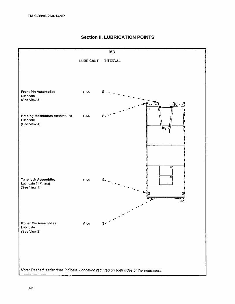
TM 9-3990-260-14&P
Section II. LUBRICATION POINTS
J-2
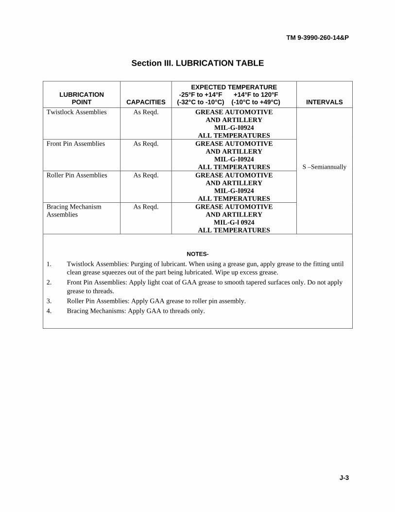
TM 9-3990-260-14&P
Section III. LUBRICATION TABLE
LUBRICATION POINT CAPACITIES
EXPECTED TEMPERATURE -25°F to +14°F +14°F to 120°F (-32°C to -10°C) (-10°C to +49°C) INTERVALS
Twistlock Assemblies As Reqd. GREASE AUTOMOTIVE AND ARTILLERY
MIL-G-I0924 ALL TEMPERATURES
Front Pin Assemblies As Reqd. GREASE AUTOMOTIVE AND ARTILLERY
MIL-G-I0924 ALL TEMPERATURES S –Semiannually
Roller Pin Assemblies As Reqd. GREASE AUTOMOTIVE AND ARTILLERY
MIL-G-I0924 ALL TEMPERATURES
Bracing Mechanism Assemblies
As Reqd. GREASE AUTOMOTIVE AND ARTILLERY
MIL-G-l 0924 ALL TEMPERATURES
NOTES-
1. Twistlock Assemblies: Purging of lubricant. When using a grease gun, apply grease to the fitting until clean grease squeezes out of the part being lubricated. Wipe up excess grease.
2. Front Pin Assemblies: Apply light coat of GAA grease to smooth tapered surfaces only. Do not apply grease to threads.
3. Roller Pin Assemblies: Apply GAA grease to roller pin assembly. 4. Bracing Mechanisms: Apply GAA to threads only.
J-3

TM 9-3990-260-14&P
Section IV. LOCALIZED LUBRICATION POINTS
• TWISTLOCK: Semiannually, apply GAA to grease fitting (1) using grease gun. • ROLLER PIN: Semiannually, apply light coat of GAA to roller pin assembly (2). • FRONT PIN: Semiannually, apply light coat of GAA to tapered surface (3) of front pin. • BRACING MECHANISM: Semiannually, apply light coat of GAA to bracing mechanism
threads (4).
J-4

TM 9-3990-260-14&P
APPENDIX K
M3A1 CROP LUBRICATION INSTRUCTIONS
Section I. LUBRICATION REQUIREMENTS
K-1. SCOPE.
This appendix gives lubrication requirements for the Container Roll-In/Out Platform (CROP) M3A1, which is the responsibility of the operator/crew.
K-2. GENERAL LUBRICATION INSTRUCTIONS.
a. Intervals. Intervals are based on normal operation. Change the interval if lubricants are contami- nated or if operating the M3A1 CROP under adverse operating conditions. Intervals are based on time.
b. Lubricate After Fording. If fording occurs, lubricate all fittings below fording depth. c. Localized Views. A reference to the appropriate localized view is given after all lubrication
entries. d. Warranty Hard Time Statement. For equipment under manufacturer's warranty, hard time
intervals shall be followed. Intervals shall be shortened if lubricants are known to be contaminated. e. Lubrication Interval Symbols. The following lubrication interval symbols used are:
S- Semiannually L-Loading
K-1

TM 9-3990-260-14&P
Section II. LUBRICATION POINTS
K-2

TM 9-3990-260-14&P
Section III. LUBRICATION TABLE
LUBRICATION POINT CAPACITIES
EXPECTED TEMPERATURE 25°F to +14°F +14°F to 120°F (-32°C to -10°C) (-10°C to +49°C) INTERVALS
A-frame Locking Pin and Locking Pin Hole
As Reqd. GREASE AUTOMOTIVE AND ARTILLERY
MIL-G-IO924 ALL TEMPERATURES
Twistlock Assemblies As Reqd. GREASE AUTOMOTIVE AND ARTILLERY
MIL-G-IO924 ALL TEMPERATURES S - Semiannually
Roller Axle Assemblies As Reqd. GREASE AUTOMOTIVE AND ARTILLERY
MIL-G-IO924 ALL TEMPERATURES
Bail Bar As Reqd. GREASE AUTOMOTIVE AND ARTILLERY
MIL-G-IO924 ALL TEMPERATURES L - Loading
NOTES 1. A-frame Locking Pin and Locking Pin Hole: Apply light coat of GAA grease to smooth tapered surfaces
only. DO NOT apply grease to threads. 2. Twistlock Assemblies: Purging of lubricant. When using a grease gun, apply grease to the fitting until
clean grease squeezes out of the part being lubricated. Wipe up excess grease. 3. Roller Axle Assemblies: Apply GAA grease to roller axles. 4. Bail Bar: Apply GAA grease to middle of bail bar.
K-3

TM 9-3990-260-14&P
Section IV. LOCALIZED LUBRICATION POINTS
• TWISTLOCK ASSEMBLIES: Semiannually, apply GAA to fitting (1) using grease gun. • A-FRAME LOCKING PIN AND LOCKING PIN HOLE: Semiannually, apply GAA on
smooth tapered surfaces only. DO NOT apply to threads. • ROLLER AXLE ASSEMBLIES: Semiannually, apply light coat of GAA to roller axle
assemblies. • BAIL BAR: When loading, apply light coat of grease to middle of bail bar.
K-4

TM 9-3990-260-14&P
APPENDIX L
TORQUE LIMITS L-1. SCOPE.
This section provide general torque limits for the screws used on the CROP. The general torque limits given in this appendix shall be used when specific torque limits are not indicated in the maintenance procedure. These general torque limits cannot be applied to screws that retain rubber components. The rubber components will be damaged before the torque limit is reached. If a special limit is not given in the maintenance instructions, tighten the screw or nut until it touches the metal bracket then tighten it one more time.
L-2. TORQUE LIMITS.
a. Screws and Nuts.
(1) Measure the diameter of the screw you are installing with a ruler. (2) Measure out one inch with a ruler and count the number of threads per inch. (3) Under the heading SIZE, look down the left-hand column until you find the diameter of the
screw you are installing (there will usually be two lines beginning with the same size). (4) In the second column under SIZE, find the number of threads per inch that matches the num-
ber of threads per inch you counted in Step 2. (Not required for metric screws). (5) To find the grade screw you are installing, match the markings on the head to the correct pic-
ture of CAPSCREW HEAD MARKINGS on the torque table. (6) Look down the column until you find the torque limit (lb.-ft. and Nm) for the diameter and
threads per inch of the screw you are installing.
L-1
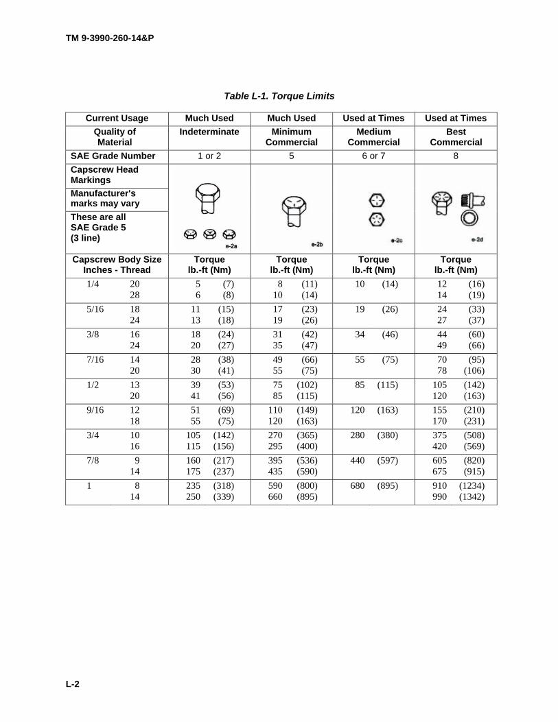
TM 9-3990-260-14&P
Table L-1. Torque Limits
Current Usage Much Used Much Used Used at Times Used at Times Quality of Material
Indeterminate Minimum Commercial
Medium Commercial
Best Commercial
SAE Grade Number 1 or 2 5 6 or 7 8 Capscrew Head Markings Manufacturer's marks may vary These are all SAE Grade 5 (3 line) Capscrew Body Size
Inches - Thread Torque
lb.-ft (Nm) Torque
lb.-ft (Nm) Torque
lb.-ft (Nm) Torque
lb.-ft (Nm) 1/4 20
28 5 6
(7) (8)
8 10
(11) (14)
10 (14) 12 14
(16) (19)
5/16 18 24
11 13
(15) (18)
17 19
(23) (26)
19 (26) 24 27
(33) (37)
3/8 16 24
18 20
(24) (27)
31 35
(42) (47)
34 (46) 44 49
(60) (66)
7/16 14 20
28 30
(38) (41)
49 55
(66) (75)
55 (75) 70 78
(95) (106)
1/2 13 20
39 41
(53) (56)
75 85
(102) (115)
85 (115) 105 120
(142) (163)
9/16 12 18
51 55
(69) (75)
110 120
(149) (163)
120 (163) 155 170
(210) (231)
3/4 10 16
105 115
(142) (156)
270 295
(365) (400)
280 (380) 375 420
(508) (569)
7/8 9 14
160 175
(217) (237)
395 435
(536) (590)
440 (597) 605 675
(820) (915)
1 8 14
235 250
(318) (339)
590 660
(800) (895)
680 (895) 910 990
(1234) (1342)
L-2
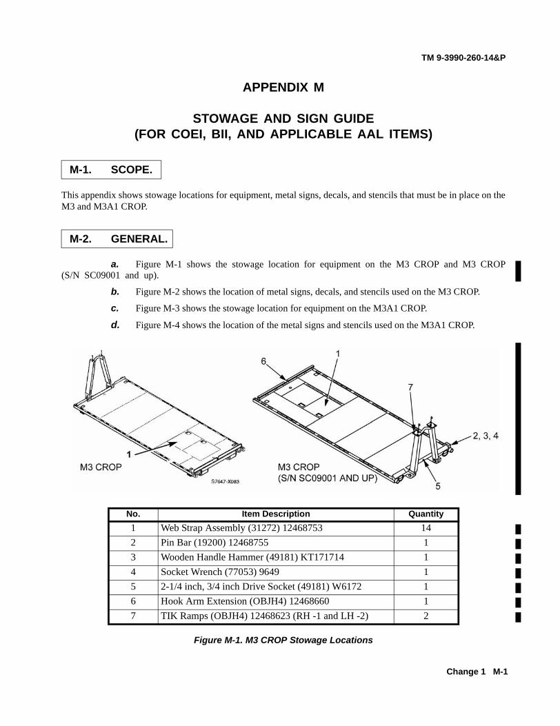
TM 9-3990-260-14&P
Change 1 M-1
APPENDIX M
STOWAGE AND SIGN GUIDE(FOR COEI, BII, AND APPLICABLE AAL ITEMS)
This appendix shows stowage locations for equipment, metal signs, decals, and stencils that must be in place on theM3 and M3A1 CROP.
a. Figure M-1 shows the stowage location for equipment on the M3 CROP and M3 CROP(S/N SC09001 and up).
b. Figure M-2 shows the location of metal signs, decals, and stencils used on the M3 CROP.
c. Figure M-3 shows the stowage location for equipment on the M3A1 CROP.
d. Figure M-4 shows the location of the metal signs and stencils used on the M3A1 CROP.
Figure M-1. M3 CROP Stowage Locations
M-1. SCOPE.
M-2. GENERAL.
No. Item Description Quantity1 Web Strap Assembly (31272) 12468753 142 Pin Bar (19200) 12468755 13 Wooden Handle Hammer (49181) KT171714 14 Socket Wrench (77053) 9649 15 2-1/4 inch, 3/4 inch Drive Socket (49181) W6172 16 Hook Arm Extension (OBJH4) 12468660 17 TIK Ramps (OBJH4) 12468623 (RH -1 and LH -2) 2
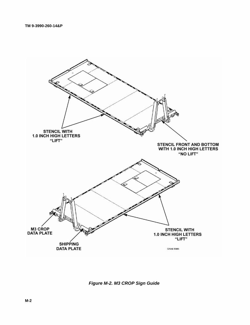
TM 9-3990-260-14&P
M-2
Figure M-2. M3 CROP Sign Guide

TM 9-3990-260-14&P
No. Item Description Quantity 1 Web Strap Assembly (19207) 12468753 14
Figure M-3. M3A 1 CROP Stowage Location
M-3

TM 9-3990-260-14&P
Figure M-4. M3A 1 CROP Sign Guide M-4
M-4

TM 9-3990-260-14&P
Index-1
ALPHABETICAL INDEX
Subject, Para
A
A-Frame Assembly Raising and Lowering Procedures, 2-11, 7-10
A-Frame Replacement, 4-12, 9-12 Abbreviations, List of, 1-10, 6-10 Additional
Authorization List, D-1Additional Inspection Criteria, 5-6, 10-6Assembly and Preparation for Use, 2-8, 7-8
B
Bracing Mechanism Replacement, 4-15Bumper Replacement, 9-19
C
Cautions and Warnings, 2-2, 7-2Common Tools and Equipment, 4-1, 5-1, 9-1, 10-1Components of End Item, and
Basic Issue Items, C-1Configuration, Equipment, 1-3, 6-3Container Transport Lock Replacement, 9-15Corrosion Prevention and
Control, 1-2, 6-2
D
Decals and Instruction Plates, 2-19, 7-19
Decontamination Procedures, Nuclear, Biological, and Chemical (NBC), 2-12, 7-12
Destruction of Army Material toPrevent Enemy Use, 1-5, 6-5
Diagram, Routing, 2-4, 7-4Door Holder Replacement, 9-18
E
EquipmentCommon Tools and
Equipment, 4-1, 5-1, 9-1, 10-1Characteristics, Capabilities, and
Features, 1-11, 6-11Location and Description of Major
Components, 1-12, 6-12Configuration, 1-3, 6-3Data, 1-13, 6-13
Subject, Para
E (CONT)
End Structure Assembly Replacement, 4-12Expendable and Durable Items List, E-1Explanation of PMCS Table Entries, 2-3, 7-3
F
Field Manuals, A-3Forms, A-2Front Load Restraint Plates Raising and
Lowering Procedures, 7-11
G
GeneralUnit PMCS Procedures, 4-8, 9-8Welding Maintenance, 5-7, 10-7Lubrication Instructions, 4-5, 9-5Maintenance Instructions, 4-11, 9-11
H
Hand Receipt, 4-6, 9-6
I
InstructionsLubrication, 2-6, 7-6General Maintenance, 4-11, 9-11
Instruction Plates, and Decals, 2-19, 7-19Inspection
Additional Inspection Criteria, 5-6, 10-6Interval Groupings, 2-5, 7-5
L
List of Abbreviations, 1-10, 6-10Load Restraint Plates (Rear)
Replacement, 9-17Loading Single CROP on PLS Truck or Trailer,
2-13, 7-13Loading/Stacking CROP on PLS/Trailer, 2-15, 7-
15Loading/Stacking CROP on PLS Truck, 2-14, 7-14Loading/Unloading ISO Container with
CROP from PLS Truck, 2-16, 7-16Loading/Unloading ISO Container with CROP
Using Forklift, 2-17, 7-17Location and Description of Major
Components, 1-12, 6-12

TM 9-3990-260-14&P
Index-2 Change 1
ALPHABETICAL INDEX- (Cont)
Subject, Para
L (CONT)
Lock and Unlock Twistlocks, 2-9, 7-9Lubrication Instructions, 2-6, 4-5, 7-6, 9-5, J-1, K-1
M
MaintenanceAllocation Chart, B-1Major Components, Location and
Description of, 1-12, 6-12Manuals, Field, A-3Miscellaneous Publications, A-5
N
Nuclear, Biological, and Chemical (NBC) Decontam-ination Procedures, 2-12, 7-12
Normal Operation, 1-14, 6-14
O
Operation, Normal, 1-14, 6-14
P
Packing and Unpacking, 4-4, 9-4Parts
Mandatory Replacement, H-1Repair (Unit Maintenance), 4-3, 9-3Repair (DS Maintenance), 5-3, 10-3Unit, Direct Support, and GeneralSupport Maintenance RPSTL, F-1
Plates, Instruction and Decals, 2-19, 7-19PMCS
Explanation of Table Entries, 2-3, 4-9, 7-3, 9-9Introduction, Unit, 4-7, 9-7Operator’s Procedures, 2-1, 7-1Unit Procedures, 4-8, 9-8Warnings and Cautions, 2-2, 7-2
PreparationStorage or Shipment, 1-4, 2-18, 6-4, 7-18Use, 2-8, 7-8
Q
Quality Assurance/Quality Control (QA/QC), 1-9, 6-9
Subject, Para
R
Raising and Lowering ProceduresA-Frame, 2-11, 7-10Front Load Restraint Plates, 7-11
ReferencesField Manuals, A-3Forms, A-2General, A-1Miscellaneous Publications, A-5Technical Manuals, A-4
RepairParts (Unit Maintenance), 4-3, 9-3Parts (DS Maintenance), 5-3, 10-3Parts and Special Tools List (RPSTL),
F-1Replacement
A-Frame, 4-12, 9-12Bumper, 9-19Container Transport Lock, 9-15Deck Plate, 5-8Door Holder, 9-18Load Restraint Plates (Rear), 9-17Roller, 4-14, 9-14Stowage Box Door, 9-20Twistlock, 4-13, 9-13Wear Plate, 9-16Reporting Equipment Improvement
Recommendations (EIRs), 1-8, 6-8Roller Replacement, 4-14, 9-14Routing Diagram, 2-4, 7-4
S
Safety, Care, and Handling, 1-6, 6-6Service Upon Receipt, 5-4, 10-4Shortened Intervals, 2-7, 7-7Special Tools
TMDE and Support Equipment, 4-2, 5-2, 9-2, 10-2
Stacking and LoadingOn PLS Truck, 2-14, 7-14On PLS Trailer, 2-15, 7-15
Storage or Shipment, Preparation for, 1-4, 6-4Stowage Box Door Replacement, 4-16, 9-20Stowage and Sign Guide, M-1

TM 9-3990-260-14&P
ALPHABETICAL INDEX - (Cont)
Subject, Para
T
Technical Manuals, A-4Tools
Common Tools and Equipment, 4-1, 9-1Special Tools, TMDE, and Support Equipment,
4-2, 9-2Identification List, I-1
TMDE and Support Equipment, Special Tools, 4-2, 5-2, 9-2, 10-2
Tools and Equipment, Common, 4-1, 5-1, 9-1, 10-1Torque Limits, L-1Troubleshooting, Operator Maintenance
Introduction, 3-1, 8-1Symptoms, 3-2, 8-2
Twistlock Lock and Unlock, 2-9, 7-9Replacement, 4-13, 9-13
U
Unloading/Loading ISO Container with CROP from PLS Truck,
2-16, 7-16ISO Container with CROP from Forklift, 2-17,
7-17 Unlock and Lock Twistlocks, 2-9, 7-9Unpacking, Packing and, 4-4, 9-4Use, Preparation for 2-8, 7-8
W
Warnings and Cautions, PMCS, 2-2, 7-2Warranty Information, 1-7, 6-7Wear Plate Replacement, 9-16Welding Maintenance, General, 5-7, 10-7
Index-3/(Index 4 blank)


By Order of the Secretary of the Army:
ERIC K. SHINSEKIGeneral, United States Army
Official: Chief of Staff
JOEL B. HUDSONAdministrative Assistant to the
Secretary of the Army9914007
DISTRIBUTION: To be distributed in accordance with the initial distribution requirements for IDN 256510, requirements for TM 9-3990-260-14&P. U.S. GOVERNMENT PRINTING OFFICE:20-646-026/00307

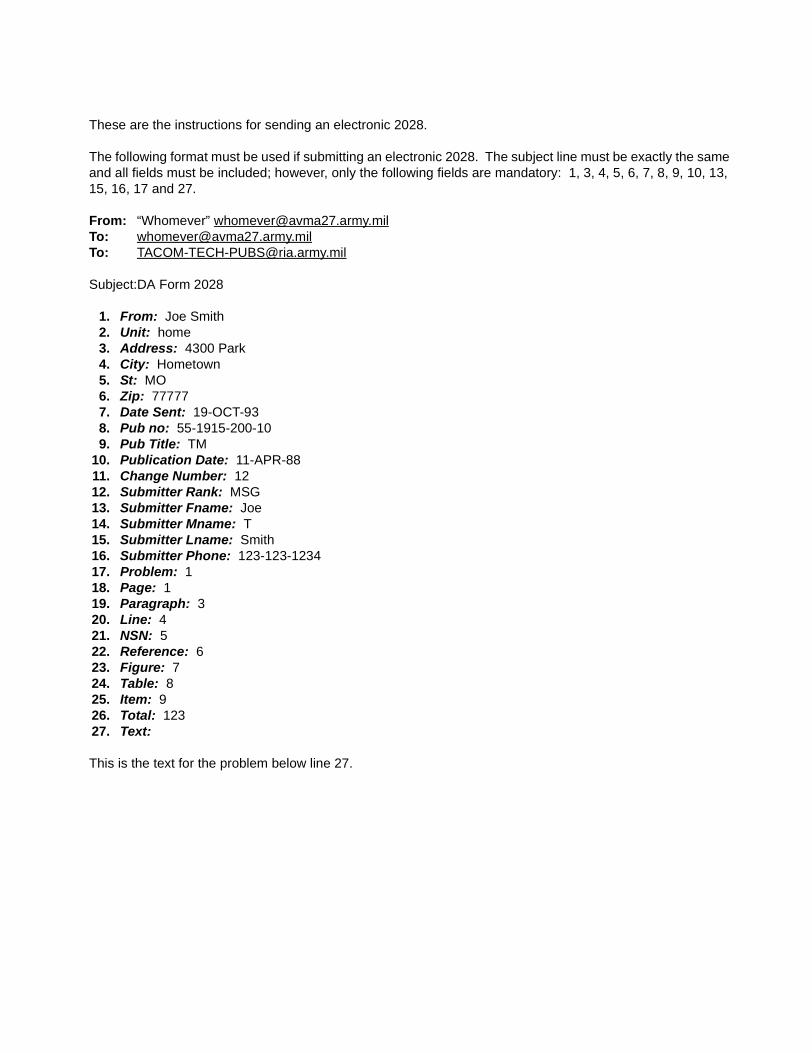
These are the instructions for sending an electronic 2028.
The following format must be used if submitting an electronic 2028. The subject line must be exactly the same and all fields must be included; however, only the following fields are mandatory: 1, 3, 4, 5, 6, 7, 8, 9, 10, 13, 15, 16, 17 and 27.
From: “Whomever” [email protected]: [email protected]: [email protected]
Subject:DA Form 2028
1. From: Joe Smith2. Unit: home3. Address: 4300 Park4. City: Hometown5. St: MO6. Zip: 777777. Date Sent: 19-OCT-938. Pub no: 55-1915-200-109. Pub Title: TM
10. Publication Date: 11-APR-8811. Change Number: 1212. Submitter Rank: MSG13. Submitter Fname: Joe14. Submitter Mname: T15. Submitter Lname: Smith16. Submitter Phone: 123-123-123417. Problem: 118. Page: 119. Paragraph: 320. Line: 421. NSN: 522. Reference: 623. Figure: 724. Table: 825. Item: 926. Total: 12327. Text:
This is the text for the problem below line 27.


RECOMMENDED CHANGES TO PUBLICATIONS AND BLANK FORMS
For use of this form, see AR 310-1; the proponent agency is the US Army Adjutant General Center.
Use Part II (reverse) for Repair Parts and Special Tool Lists (RPSTL) and Supply Catalogs/Supply Manuals (SC/SM).
DATE:
Date form is filled out.
TO: (Forward to proponent of publication or form) (Include ZIP Code)
Mailing address found on title block page.FROM: (Activity and location) (Include ZIP Code)
Your mailing address.PART I - ALL PUBLICATIONS (EXCEPT RPSTL AND SC/SM) AND BLANK FORMS
PUBLICATION/FORM NUMBER:
TM X-XXXX-XXX-XXXDATE:
Date of the TM.TITLE:
Title of TM.ITEMNO.
PAGENO.
PARA-GRAPH
LINENO.
FIGURENO.
TABLENO.
RECOMMENDED CHANGES AND REASON(Exact wording of recommended change must be given)
0019 00 1 3 1 1 Step No. 2 says to secure doors open with locking bar or hooks from where to what? The bars or hooks are not identified.
0019 00 4 4 1 1 Step No. 19 states to remove locking bars, pins or hooks from where to what? The bars, pins or hooks are not identified. Where are they stored?
* Reference to line numbers within the paragraph or subparagraph.
TYPED NAME, GRADE OR TITLE
Doe, John, CPL
TELEPHONE EXCHANGE/AUTOVON, PLUS EXTENSION
755-1313
SIGNATURE
CPL John Doe
DA FORM 2028, FEB 74 REPLACES DA FORM 2028, 1 DEC 68, WHICH WILL BE USED. USAPA V3.01
SAMPLE

TO: (Forward to proponent of publication or form) (Include ZIP Code)
FROM: (Activity and location) (Include ZIP Code)
DATE:
PART II- REPAIR PARTS AND SPECIAL TOOL LISTS AND SUPPLY CATALOGS/SUPPLY MANUALS
PUBLICATION/FORM NUMBER:
TM X-XXXX-XXX-XXXDATE:
Date of the TM.TITLE:
Title of TM.
PAGENO.
COLMNO.
LINENO.
FEDERAL STOCKNUMBER
REFERENCENO.
FIGURENO.
ITEMNO.
TOTAL NO.OF MAJOR
ITEMSSUPPORTED
RECOMMENDED ACTION
PART III - REMARKS (Any general remarks or recommendations, or suggestions for improvement of publications and blank forms. Additional blank sheets may be used if more space is needed.)
* Reference to line numbers within the paragraph or subparagraph.
TYPED NAME, GRADE OR TITLE
Doe, John, CPL
TELEPHONE EXCHANGE/AUTOVON, PLUS EXTENSION
755-1313
SIGNATURE
CPL John Doe
U.S. GOVERNMENT PRINTING OFFICE 1981 341-646/8606
SAMPLE

RECOMMENDED CHANGES TO PUBLICATIONS AND BLANK FORMS
For use of this form, see AR 310-1; the proponent agency is the US Army Adjutant General Center.
Use Part II (reverse) for Repair Parts and Special Tool Lists (RPSTL) and Supply Catalogs/Supply Manuals (SC/SM).
DATE:
TO: Commander AMSTA-LC-LPIT / TECH PUBS, TACOM-RI 1 Rock Island Arsenal Rock Island, IL 61299-7630
FROM:
PART I - ALL PUBLICATIONS (EXCEPT RPSTL AND SC/SM) AND BLANK FORMS
PUBLICATION/FORM NUMBER:
TM 9-3990-260-14&PDATE:
27 JULY 2001TITLE:
Operator's, Unit, Direct Support and General Support Maintenance Manual (Including Repair Parts and Special Tools List) for Container Roll-In/ Out Platform (Crop) Model M3 (NSN 3990-01-442-2751); Container Roll-in/ Out Platform (Crop) Model M3A1 (3990-01-450-5671)
ITEMNO.
PAGENO.
PARA-GRAPH
LINENO.
FIGURENO.
TABLENO.
RECOMMENDED CHANGES AND REASON(Exact wording of recommended change must be given)
* Reference to line numbers within the paragraph or subparagraph.
TYPED NAME, GRADE OR TITLE
TELEPHONE EXCHANGE/AUTOVON, PLUS EXTENSION
SIGNATURE
DA FORM 2028, FEB 74 REPLACES DA FORM 2028, 1 DEC 68, WHICH WILL BE USED. USAPA V3.01

TO: (Forward to proponent of publication or form) (Include ZIP Code)
FROM: (Activity and location) (Include ZIP Code)
DATE:
PART II- REPAIR PARTS AND SPECIAL TOOL LISTS AND SUPPLY CATALOGS/SUPPLY MANUALS
PUBLICATION/FORM NUMBER:
DATE:
TITLE:
PAGENO.
COLMNO.
LINENO.
FEDERAL STOCKNUMBER
REFERENCENO.
FIGURENO.
ITEMNO.
TOTAL NO.OF MAJOR
ITEMSSUPPORTED
RECOMMENDED ACTION
PART III - REMARKS (Any general remarks or recommendations, or suggestions for improvement of publications and blank forms. Additional blank sheets may be used if more space is needed.)
* Reference to line numbers within the paragraph or subparagraph.
TYPED NAME, GRADE OR TITLE
TELEPHONE EXCHANGE/AUTOVON, PLUS EXTENSION
SIGNATURE
U.S. GOVERNMENT PRINTING OFFICE 1981 341-646/8606

RECOMMENDED CHANGES TO PUBLICATIONS AND BLANK FORMS
For use of this form, see AR 310-1; the proponent agency is the US Army Adjutant General Center.
Use Part II (reverse) for Repair Parts and Special Tool Lists (RPSTL) and Supply Catalogs/Supply Manuals (SC/SM).
DATE:
TO: Commander AMSTA-LC-LPIT / TECH PUBS, TACOM-RI 1 Rock Island Arsenal Rock Island, IL 61299-7630
FROM:
PART I - ALL PUBLICATIONS (EXCEPT RPSTL AND SC/SM) AND BLANK FORMS
PUBLICATION/FORM NUMBER:
TM 9-3990-260-14&PDATE:
27 JULY 2001TITLE:
Operator's, Unit, Direct Support and General Support Maintenance Manual (Including Repair Parts and Special Tools List) for Container Roll-In/ Out Platform (Crop) Model M3 (NSN 3990-01-442-2751); Container Roll-in/ Out Platform (Crop) Model M3A1 (3990-01-450-5671)
ITEMNO.
PAGENO.
PARA-GRAPH
LINENO.
FIGURENO.
TABLENO.
RECOMMENDED CHANGES AND REASON(Exact wording of recommended change must be given)
* Reference to line numbers within the paragraph or subparagraph.
TYPED NAME, GRADE OR TITLE
TELEPHONE EXCHANGE/AUTOVON, PLUS EXTENSION
SIGNATURE
DA FORM 2028, FEB 74 REPLACES DA FORM 2028, 1 DEC 68, WHICH WILL BE USED. USAPA V3.01
TO: (Forward to proponent of publication or form) (Include ZIP Code)
FROM: (Activity and location) (Include ZIP Code)
DATE:
PART II- REPAIR PARTS AND SPECIAL TOOL LISTS AND SUPPLY CATALOGS/SUPPLY MANUALS
PUBLICATION/FORM NUMBER:
DATE:
TITLE:
PAGENO.
COLMNO.
LINENO.
FEDERAL STOCKNUMBER
REFERENCENO.
FIGURENO.
ITEMNO.
TOTAL NO.OF MAJOR
ITEMSSUPPORTED
RECOMMENDED ACTION
PART III - REMARKS (Any general remarks or recommendations, or suggestions for improvement of publications and blank forms. Additional blank sheets may be used if more space is needed.)
* Reference to line numbers within the paragraph or subparagraph.
TYPED NAME, GRADE OR TITLE
TELEPHONE EXCHANGE/AUTOVON, PLUS EXTENSION
SIGNATURE
U.S. GOVERNMENT PRINTING OFFICE 1981 341-646/8606


PIN: 077334-000

This fine document...
Was brought to you by me:
Liberated Manuals -- free army and government manuals
Why do I do it? I am tired of sleazy CD-ROM sellers, who take publicly available information, slap “watermarks” and other junk on it, and sell it. Those masters of search engine manipulation make sure that their sites that sell free information, come up first in search engines. They did not create it... They did not even scan it... Why should they get your money? Why are not letting you give those free manuals to your friends?
I am setting this document FREE. This document was made by the US Government and is NOT protected by Copyright. Feel free to share, republish, sell and so on.
I am not asking you for donations, fees or handouts. If you can, please provide a link to liberatedmanuals.com, so that free manuals come up first in search engines:
<A HREF=http://www.liberatedmanuals.com/>Free Military and Government Manuals</A>
– SincerelyIgor Chudovhttp://igor.chudov.com/
– Chicago Machinery Movers