TM 9-2320-279-24P-2 9-2320-279-34P-1, TM 9-2320-279-34P2 ...

TM 9-2320-270-20-3
HEADQUARTERS, DEPARTMENT OF THE ARMY
JUNE 1986


CHANGE
NO. 1
TM9-2320-270-20-3C-1
HEADQUARTERSDEPARTMENT OF THE ARMY
Washington D.C., 28 February 1991
ORGANIZATIONAL MAINTENANCE
VOLUME 3 OF 3
TRUCK, TRACTOR, COMMERCIAL
HEAVY EQUIPMENT TRANSPORTER
(C-HET) 85,000 GVWR, 8X6, M911
(NSN 2320-01-025-3733)
TM 9-2320-270-20-3, dated 10June 1986, is changed as follows:
1. Change to narrative materiel is indicated by a vertical bar in the outside margin of the page. Added orrevised illustrations are indicated by a vertical bar adjacent to the identification number.
2. Remove old pages and insert new pages as indicated below.
3. File this change sheet in front of the publication for reference purposes.
Remove Pages Insert Pages
i and ii i and ii4-1087 and 4-1088 4-1087 and 4-1088F-23 through F-28 F-23 through F-28
By Order of the Secretary of the Army:CARL E. VUONO
General, United States ArmyChief of Staff
Official:
PATRICIA P. HICKERSON
Colonel, United States ArmyThe Adjutant General
Distribution:To be distributed in accordance with DA Form 12–38, Block 0290, Unit maintenance
requirements for TM 9-2320-270-20-3.


W A R N I N G
Make sure battery ground cable is disconnected to prevent possible injury and damageto the electrical system.
W A R N I N G
Make sure all pressure is drained from air system before disconnecting air lines. Partsunder pressure can, when removed, fly off with great force causing injury to personnel.
W A R N I N G
Do not get between wheels and fender, or between other moving and stationary parts,while assistant is turning wheels. There is no clearance for personnal in these areaswhen turning vehicle.
Hearing protection must be worn while working under truck with engine running to pre-vent possible ear injury.
W A R N I N G
Do not use open-end wrench to break stop screws loose. Open-end wrench will slipcausing injury to personnel.
W A R N I N G
Some parts are heavy. Be careful when handling them. Lifting equipment is neededwhen parts weigh over 50 pounds (23 kg) for a single person lift, over 100 pounds(45 kg) for a two person lift, and over 150 pounds (68 kg) for a three or more personlift. Do not try to handle heavy parts without lifting equipment. Keep clear of heavy partssupported only by lifting equipment. Failure to observe this precaution could causeserious injury or death of personnel.
W A R N I N G
When removing or installing mounting hardware, assistants must hold spare tire mountto prevent it falling and causing injury to personnel.
W A R N I N G
Leather gloves must be worn when handling cable to prevent cuts and scrapes. Never letcable run through hands. Broken and frayed wires can cause injury.
T M 9 - 2 3 2 0 - 2 7 0 - 2 0 - 3
W A R N I N G
a
TM9-2320-270-20-3
W A R N I N G
Drycleaning solvent P-D-680 is toxic and flammable. Wear protective goggles andgloves and use only in a well ventilated area. Avoid contact with skin, eyes, and clothesand don’t breathe vapors. Do not use near open flame or excessive heat. The flashpointis 100°F to 138°F (38° to 59°C). If you become dizzy while using cleaning solvent, getfresh air immediately and get medical aid. If contact with eyes is made, wash your eyeswith water and get medical aid immediately.
W A R N I N G
Rubber cement and its fumes burn easily. Do not smoke or have open flame nearby whileusing. Use in well-ventilated area. Failure to observe these precautions can causeserious burns to personnel.
Hearing protection must be worn while adjusting air horns. Air horns are very loud. Ifhearing protection is not worn, permanent damage could result.
W A R N I N G
Be careful when removing radiator cap. If engine is hot, escaping steam could burnyou. Using a rag, cover radiator cap to protect your hand. Unscrew cap just enough toallow any built-up steam to escape. When all pressure has been relieved, unscrew capthe rest of the way, and take off of radiator.
W A R N I N G
Naptha and its fumes are harmful and flammable. Do not smoke or use near open flamewhile using. Use only in well-ventilated area. Naptha can catch fire and fumes canexplode causing serious injury.
W A R N I N G
b

*TM9-2320-270-20-3
TECHNICAL MANUAL HEADQUARTERSDEPARTMENT 0F THE ARMY
NO. 9-2320-270-20-3 WASHINGTON, DC 10 JUNE 1986
ORGANIZATIONAL MAINTENANCE MANUAL
TRUCK, TRACTOR, COMMERCIALHEAVY EQUIPMENT TRANSPORTER (C-HET)
85,000 GVWR, 8 X 6, M911(NSN 2320-01-025-3733)
CURRENT AS OF NOVEMBER 1985
REPORTING ERRORS AND RECOMMENDING IMPROVEMENTS
You can help Improve this manual. If you find any mistakes or if you know of a way toImprove the procedures, please let us know. Mail your letter, DA Form 2028(Recommended Changes to Publications and Blank Forms), or DA Form 2028-2 locatedin the back of this manual direct to: Commander, US Army Tank-Automotive Command,ATTN: AMSTA-MB, Warren, Mi 48397=5000. A reply will be sent to you.
TABLE OF CONTENTS
VOLUME 3 OF 3
CHAPTER 4
Section XIII.section XIV.Section XV.Section XVI.Section XVII.Section XVIII.Section XIX.
APPENDIX A
Page
MAINTENANCE INSTRUCTIONS - CONTINUED . . . . . . . . . . . . . . . . . . . . . . . . . . . . . . . . . . 4-937
Steering . . . . . . . . . . . . . . . . . . . . . . . . . . . . . . . . . . . . . . . . . . . . . . . . . 4-937Frame and Towing Attachment Maintenance . . . . . . . .. . . . . . . . . . . . . 4-1042Springs, Shock Absorbers, and Torque Rods . . . . . . . . . . . . . . . . . . . 4-1085Cab and Body Maintenance. . . . . . . . . . . . . . . . . . . . . . . . . . . . . . . . . . . . . . . . . . . . . . . . . . . . . . . . 4-1088Winches . . . . . . . . . . . . . . . . . . . . . . . . . . . . . . . . . . . . . . . . . . . . . . . . . . . . . . . . . . . . . . . . . . . . . . . . . . . . . . . . . . . . . . . . . . . . . . .4-1135Accessories Maintenance . . . . . . . . . . . . . . . . . . . . . . . . . . . . . . . . . . . . . .... 4-1177Gages, Non-Electric . . . . . . . . . . . . . . . . . . . . . . . . . . . . . . . . . . . . . . . . . . . . . . . . . . . . . . . . . . . . ..... .. 4-1330
REFERENCES . . . . . . . . . . . . . . . . . . . . . . . . . . . . . . . . . . . . . . . . . . . . . . . .... . . . . . . . . . . . . . . . . . . . . . ..A-1
APPENDIX B MAINTENANCE Allocation CHART . . . . . . . . . . . . . . . . . . . . . . . ........ . . . . . . . B-1
APPENDIX C EXPENDABLE SUPPLIES AND MATERIALS LIST . . . . . . . . . . . . . . . . . . . . . . . . . . . . C-1
APPENDIX D MANUFACTURED ITEMS (NOT APPLICABLE) . . . . . . . . . . . . . . . . . . . . . . . . . . . . . . ...... D-1
*This manual together with TM 9-2320-270-20-1 and TM 9-2320-270-20-2 supersedes TM 9-2320-270-20,dated 15 November 1977.
i

TM9-2320-270-20-3
APPENDIX E
APPENDIX F
GLOSSARY
I N D E X
TABLE OF CONTENTS - CONTINUED
VOLUME 3 0F 3 - CONTINUED
Page
TORQUE LIMITS . . . . . . . . . . . . . . . . . . . . . . . . . . . . . . . . . . . . . . . . . . . . . . . . . . . . . . . . . . . . . . . . . . . . . . . . . . . . . . . . . . . . . . . . . . . E-1
S C H E M A T I C D I A G R A M S . . . . . . . . . . . . . . . . . . . . . . . . . . . . . . . . . . . . . . . . . . . . . . . . . . . . . . . . . . . . . . . . . ... . . F-1
. . . . . . . . . . . . . . . . . . . . . . . . . . . . . . . . . . . . . . . . . . . . . . . . . . . . . . . . . . . . . . . . . . . . . . . . . . . . . . . . . . . . . . . . . . . . . . . . . . . . . . . . . . . . . . . . . . . . . . . . Glos-1
. . . . . . . . . . . . . . . . . . . . . . . . . . . . . . . . . . . . . . . . . . . . . . . . . . . . . . . . . . . . . . . . . . . . . . . . . . . . . . . . . . . . . . . . . . . . . . . . . . . . . . . . . . . . . . . . . . . . . . . . Index-1
ii

TM9-2320-270-20-3
CHAPTER 4 - C O N T I N U E D
M A I N T E N A N C E I N S T R U C T I O N S - C O N T I N U E D
Section XIII. STEERING
Battery Box Bracket toBooster Hoses . . . . . . . . . . . . . . . . . . . . . . . . . . . . . . . . . . . . . . . . . .
Booster Cylinder . . . . . . . . . . . . . . . . . . . . . . . . . . . . . . . . . . . . . . . . . . .Dash Brace . . . . . . . . . . . . . . . . . . . . . . . . . . . . . . . . . . . . . . . . . . . . . . . . . . . .Pitman Arm . . . . . . . . . . . . . . . . . . . . . . . . . . . . . . . . . . . . . . . . . . . . . . . . . . .Pitman Arm Stop Bracket . . . . . . . . . . . . . . . . . . . . . . . . . . . .Pitman Arm to Booster Drag Link . . . . . . . . . . . . . . .Power Steering Pump . . . . . . . . . . . . . . . . . . . . . . . . . . . . . . . . . . .Power Steering Pump Supply Hose . . . . . . . . . . . .Power Steering Reservoir . . . . . . . . . . . . . . . . . . . . . . . . . . . . .Power Steering Pump to Battery
Box Bracket Pressure Hose . . . . . . . . . . . . . . . . . . . . .
Page
4-10044-10164-9434-9784-9744-9624-9854-10124-1024
4-999
Power Steering Pump to ReservoirReturn Hose . . . . . . . . . . . . . . . . . . . . . . . . . . . . . . . . . . . . . . . . . . . .
Reservoir to Battery Box BracketHose . . . . . . . . . . . . . . . . . . . . . . . . . . . . . . . . . . . . . . . . . . . . . . . . . . . . . . . .
Steering Alinement . . . . . . . . . . . . . . . . . . . . . . . . . . . . . . . . . . . . .Steering Column Bracket . . . . . . . . . . . . . . . . . . . . . . . . . . .Steering Gear . . . . . . . . . . . . . . . . . . . . . . . . . . . . . . . . . . . . . . . . . . . . . .Steering Shaft Grease Fitting . . . . . . . . . . . . . . . . . . . .Steering Wheel . . . . . . . . . . . . . . . . . . . . . . . . . . . . . . . . . . . . . . . . . . .Tie Rod . . . . . . . . . . . . . . . . . . . . . . . . . . . . . . . . . . . . . . . . . . . . . . . . . . . . . . . .Wheel to Booster Drag Link . . . . . . . . . . . . . . . . . . . . . . .
Page
4-1008
4-9934-10354-9404-9814-9534-9374-9684-955
STEERING WHEEL
This task covers:
a. Removal (page 4-938)b. Installation (page 4-938)
INITIAL SETUP
Tools
Bar, pryHandle, ratchet, 1/2-inch drivePuller, steering wheelScrewdriver, flat-tip, 3/16-inchSocket, 1 1/4-inch, 1/2-inch drive
Equipment Condition
Battery ground cable disconnected(page 4-444).
Left side of hood open and left hood sidepanel removed (TM 9-2320-270-10).
Personnel Required
Two
4-937

TM9-2320-270-20-3
STEERING WHEEL - CONTINUED
ACTIONLOCATION ITEM REMARKS
REMOVAL
1. Truck
3.
4.
5.
6.
Base plate (5) tosteering wheel (1)
Steering wheel (1)
Steering wheel (1)to steering columnshaft (8)
Steering column
2. Steering wheel (1) Horn button (2),contact ring (3),and spring (4)
Two screws (6) andscrew (7)
Base plate (5)
Nut (9)
Steering wheel (1)
Park on level surface with frontwheels positioned straight ahead(TM 9-2320-270-10).
a. Push down and turn counterclockwise.b. Take out.
Using screwdriver, unscrew and take out.Note location of longer screw.
Take out.
Using 1 1/4-inch socket and handle,unscrew and take off.
Using puller, pull off.shaft (8)
INSTALLATION
7. Steering column (10) Steering column Have assistant push up until it is allshaft (8) the way up.
8. Steering column Steering wheel (1) Place in position.shaft (8)
9. Steering wheel (1) Nut (9) Screw on and tighten using 1 1/4-inchto steering column socket and handle.shaft (8)
4-938

TM9-2320-270-20-3
STEERING WHEEL - CONTINUED
LOCATION ITEMACTION
REMARKS
10.
11.
12.
13.
Steering wheel (1) Base plate (5) Put in place.
Screw (7) a. Note location from removal.b. Screw in and tighten using screwdriver.
Base plate (5) to Two screws (6) Screw in and tighten using screwdriver.steering wheel (1)
Steering wheel (1) Spring (4), contact a. Put in place.ring (3), and horn b. Push down and turn clockwise.button (2)
N O T E
FOLLOW-ON MAINTENANCE:
1. Install left hood side panel and close left side of hood (TM 9-2720-270-10).2. Connect battery ground cable (page 4-444).
TASK ENDS HERE
TA240595
4-939

TM9-2320-270-20-3
STEERING COLUMN BRACKET
This task covers:
a. Removal (page 4-940)b. Installation (page 4-942)
INITIAL SETUP
ToolsMaterials/Parts – Continued
Extension, 12-inch, 3/8-inch driveHandle, ratchet, 3/8-inch driveKey, socket head screw, 5/16-inchKnife, pocketSocket, 1/2-inch, 3/8-inch driveWrench, box, 1/2-inchWrench, box, 9/16-inch
Materials/Parts
Lockwasher, steering column bracket brace todash brace (two required)
Lockwasher, steering column mounting plateto floor (two required)
Personnel Required
Two
Equipment Condition
Bushing, rubberLockwasher, steering column bracket
Left hood side panel removed
cap to steering column bracket(TM 9-2320-270-10).
brace (two required)—
ACTION
LOCATION ITEM REMARKS
REMOVAL
1. Steering column (1) Rubber grommet (2) Pull up.
2. Floor (3) Floor mat (4) Pull back.
3. Steering column TWO capscrews (6), a. With help from assistant and using
mounting plate nuts (7), and 1/2-inch box wrench, 1/2-inch socket,
(5) to floor (3) Iockwasher (8) handle, and extension, unscrew andtake out.
b. Get rid of Iockwasher (8).
4. Steering columnbracket cap (9) tosteering columnbracket brace (10)
5.
Two socket head a. Using 5/16-inch key and 9/16-inch
screws (11), nuts box wrench, unscrew and take off.
(12), lockwashers b. Get rid of Iockwashers (13).
(13), and bracket c. Take out screws (11).
cap (9)
Steering column (1) Lower carefully and rest on front seat.
4-940

TM9-2320-270-20-3
STEERING COLUMN BRACKET - CONTINUED
LOCATIONACTION
ITEM REMARKS
6. Steering column (1) Bracket base (14) Take off.
7. Rubber bushing (15) a. Using knife, cut off.b. Get rid of.
N O T E
If not removing steering column
8. Instrument panel
9. Steering column Two capscrews (17),bracket brace (10) nuts (18), lock-to dash brace (16) washers (19), and
bracket brace (10)
bracket brace, go to step 13.
Open (page 4-244).
a. Using 1/2-inch box wrench, 1/2-inchsocket, extension, and handle, unscrewand take off with bracket brace.
b. Get rid of Iockwashers (19).
TA240596
4-941

TM9-2320-270-20-3
STEERING COLUMN BRACKET - CONTINUED
ACTIONLOCATION ITEM REMARKS
INSTALLATION
N O T E
If not installing steering column bracket brace, go to step 13.
10.
11.
12.
13.
14.
15.
16.
17.
18.
19.
20.
21•
Dash brace (1)
Bracket brace (2)to dash brace (1)
Steering column (6)
Bracket cap (9) andbracket brace (8)to dash brace (1)
Steering columnmounting plate (13)to floor (14)
Bracket cap (9) tobracket brace (8)
Floor (14)
Steering column (6)
Bracket brace (2)
Two capscrews (3),new Iockwashers(4), and nuts (5)
Instrument panel
New rubberbushing (7)
Bracket base (8)
Steering column (6)
Bracket cap (9) andbracket base (8)
Two screws (10), newIockwashers (11),and nuts (12)
Two capscrews (15),new Iockwashers(16), and nuts (17)
Two screws (10)and nuts (12)
Floor mat (18)
Grommet (19)
Put in place.
Screw in and tighten using 1/2-inch boxwrench, 1/2-inch socket, extension, andhandle.
Close (page 4-244).
a. Using knife, cut.b. Put in place.
Put in.
Have assistant raise into place and hold.
Put in place.
Screw in but do not tighten using 5/16-inch key and 9/16-inch box wrench.
With help from assistant, screw on andtighten using 1/2-inch box wrench, 1/2-inch socket, handle, and extension.
Using 5/16-inch key and 9/16-inch boxwrench, tighten.
Put in place.
Push down.
4-942

TM9-2320-270-20-3
STEERING COLUMN BRACKET - CONTINUED
N O T E
FOLLOW-ON MAINTENANCE: Install left side hood panel (TM 9-2320-270-10).
TASK ENDS HERE
DASH BRACE
This task covers:
a. Removal (page 4-944)c. Assembly (page 4-948)
b. Disassembly (page 4-948)d. Installation (page 4-948)
INITIAL SETUP
Tools
Hammer, plasticHandle, ratchet, 3/8-inch drivePliers, diagonal-cuttingPliers, long-nose, roundScrewdriver, cross-tip, number 2Screwdriver, flat-tip, 3/8-inchSocket, 3/8-inch, 3/8-inch driveSocket, 7/16-inch, 3/8-inch driveSocket, 1/2-inch, 3/8-inch driveWrench, box, 1/2-inchWrench, open-end, 7/16-inchWrench, open-end, 1/2-inchWrench, open-end, 9/16-inchWrench, open-end, 5/8-inch
Materials/Parts
Lockwasher, air manifold to dashbrace (two required)
Lockwasher, turn signal flasherholder to dash brace
Lockwasher, steering column bracket braceto dash brace (two required)
Lockwasher, dash brace to firewall(two required)
Lockwasher, dash brace to dashboard(two required)
Lockwasher, steering column mounting plateto floor (two required)
Soap, liquid (item 14, appendix C)Wrap, tie (item 24, appendix C)
TA240597
4 - 9 4 3

DASH BRACE - CONTINUED
INITIAL SETUP – CONTINUED
Personnel Required
Two
Equipment Condition
Battery ground cable disconnected(page 4-444).
Equipment Condition – Continued
Air system drained (TM 9-2320-270-10).Left hood side panel removed and left side
of hood open (TM 9-2320-270-10).
ACTIONLOCATION ITEM REMARKS
REMOVAL
Make sure battery ground cable is disconnected to prevent possible injury and damageto the electrical system.
1. Dash brace (1) Connector (2) and Unplug.horn button wire (3)
2. Air hoses Tie wrap (7) a. Using cutting pliers, cut and take off.(4), (5), and (6) b. Get rid of.
Make sure all pressure is drained from air system before disconnecting air lines. Partsunder pressure can, when removed, fly off with great force causing injury to personnel.
3. Air line 27 (8) to Nut (10)trailer brakehandle assembly (9)
4. Air line 663 (11) Nut (12)to trailer brakehandle assembly (9)
5. Trailer brake Air line 27 (8) andhandle assembly (9) air line 663 (11)
6. Adapters (13) or Two inserts (14)air lines 27 (8)and 663 (11)
Using 5/8-inch and 9/16-inch open-endwrenches, unscrew.
Using 5/8-inch and 9/16-inch open-endwrenches, unscrew.
Pull out and push up through hole indash brace.
Using long-nose pliers, take out.
4 - 9 4 4
W A R N I N G
W A R N I N G
T M 9 - 2 3 2 0 - 2 7 0 - 2 0 - 3

TM9-2320-270-20-3
DASH BRACE - CONTINUED
LOCATIONACTION
ITEM REMARKS
7. Instrument panel Open (page 4-244).
8. Turn signal flasher Turn signalholder (15)
Pull out.flasher (16)
TA240598
4-945

DASH BRACE - CONTINUED
ACTION
LOCATION ITEM REMARKS
REMOVAL - CONTINUED
9. Air line 533 (1)to air manifold (2)
10. Air manifold (2)elbow (4)
11. Nut (3) orelbow (4)
12. Air manifold (2)to dash brace (6)
13. Dash brace (6)
Nut (3) Using 5/8-inch and 1/2-inch open-endwrenches, unscrew.
Air line 533 (1) Pull out and push down through hole.
insert (5) Using long-nose pliers, pull out.
TWO capscrews (7), a. Using 7/16-inch open-end wrench,
nuts (8), and lock- 7/16-inch socket, and handle, un-
washers (9) screw and take off.b. Get rid of Iockwashers (9).
Air manifold (2) Take out.
T A 2 4 0 5 9 9
4 - 9 4 6

TM9-2320-270-20-3
DASH BRACE- CONTINUED
LOCATIONACTION
ITEM REMARKS
14. Steering column (10) Rubber grommet (11) Pull up.
15. Floor (12) Floor mat (13) Pull back.
16. Steering column Two screws (15), a. With help of assistant, using 1/2-inchmounting plate (14) nuts (16), and lock- box wrench, 1/2-inch socket, andto floor (12) washers (17) ratchet handle, unscrew and take out.b. Get rid of Iockwashers (17).
TA240600
4-947

DASH BRACE- CONTINUED
ACTIONLOCATION ITEM REMARKS
REMOVAL–CONTINUED
17. Steering columnbracket brace (1)to dash brace (2)
Two capscrews (3),nuts (4), and lock-washers (5)
a. Using 1/2-inch box wrench, 1/2-inchsocket, and handle, unscrew and takeout.
b. Get rid of Iockwashers (5).
18. Steering column (6) Lower and rest on front seat.
Two capscrews (8),12 washers (9),two Iockwashers(10), and nuts (11)
a. With help of assistant, using 1/2-inchbox wrench, 1/2-inch socket, andhandle, unscrew and take out.
b. Get rid of Iockwashers (10).
19. Dash brace (2)to firewall (7)
Two capscrews (1 3),nuts (14), washers(15), and lock-washers (16)
a. Using 1/2-inch box wrench, 1/2-inchsocket, and handle, unscrew and takeout.
b. Get rid of Iockwashers (16).
20. Dash brace (2)to dashboard (12)
Take out.Dash brace (2)21.
DISASSEMBLY
22. Turn signal flasherholder (17) to dashbrace (2)
Screw (18), nut(19), Iockwasher(20), and turn signalflasher holder (17)
a. Using cross-tip screwdriver, 3/8-inchsocket, and handle, unscrew and takeoff.
b. Get rid of Iockwasher (20).
ASSEMBLY
23. Dash brace (2) Put in place.Turn signal flasherholder (17)
Screw in and tighten using cross-tip screwdriver, 3/8-inch socket, and handle.
24. Turn signal flasherholder (17) to dashbrace (2)
INSTALLATION
25. Dash brace (2)
Screw (18), newIockwasher (20),and nut (19)
Put through hole in center.
Place in postion.
Air lines 533 (21),27 (22), and 663 (23)
Dash brace (2)26.
4-948
TM9-2320-270-20-3

TM9-2320-270-20-3
DASH BRACE- CONTINUED
LOCATION ITEMACTION
REMARKS
27. Dash brace (2) Two capscrews (8), With help of assistant, screw in andto firewall (7) 12 washers (9), tighten using 1/2-inch box wrench, 1/2-
two new Iockwashers inch socket, and handle.(10), and nuts (11)
28. Dash brace (2)to dashboard (12)
Two capscrews (13), Using 1/2-inch box wrench, 1/2-inchnew Iockwashers socket, and handle, tighten.(16), washers (15),and nuts (14)
TA240601
4-949

TM9-2320-270-20-3
DASH BRACE- CONTINUED
ACTIONLOCATION ITEM REMARKS
INSTALLATION – CONTINUED
29.
30.
31.
32.
33.
34.
35.
36.
37.
Steering columnbrace (2) todash brace (3)
Steering columnmounting plate (7)to floor (8)
Floor (8)
Steering column (1)
Dash brace (3)
Air manifold (14)to dash brace (3)
Elbow (18)
Air manifold (14)
Steering column (1)
Two capscrews (4),nuts (5), and newIockwashers (6)
Two capscrews (9),nuts (10), and newIockwashers (11)
Floor mat (12)
Rubber grommet (13)
Air manifold (14)and two screws (15)
Two screws (15), newIockwashers (16),and nuts (17)
Insert (19)
Air line 533 (20)
Have assistant lift into place and hold.
Screw in and tighten using 1/2-inch boxwrench, 1/2-inch socket, and handle.
With help of assistant, screw in and tightenusing 1/2-inch box wrench, 1/2-inch sock-et, and handle.
Place in position.
Push down.
Put in place.
Screw in and tighten using 7/16-inch open-end wrench, 7/16-inch socket, andhandle.
Using plastic hammer, tap in.
a. Lube lightly with soap solution and pushin.
36. Turn signal Turn signalflasher holder (21) flasher (22)
39. Instrument panel
b. Screw on and tighten using 5/8-inchand 1/2-inch open-end wrenches.
Push in.
Close (page 4-244).
4-950

TM9-2320-270-20-3
DASH BRACE - CONTINUED
T A 2 4 0 6 0 2
4 - 9 5 1
TM9-2320-270-20-3
DASH BRACE - CONTINUED
ACTION
LOCATION ITEM REMARKS
INSTALLATION - CONTINUED
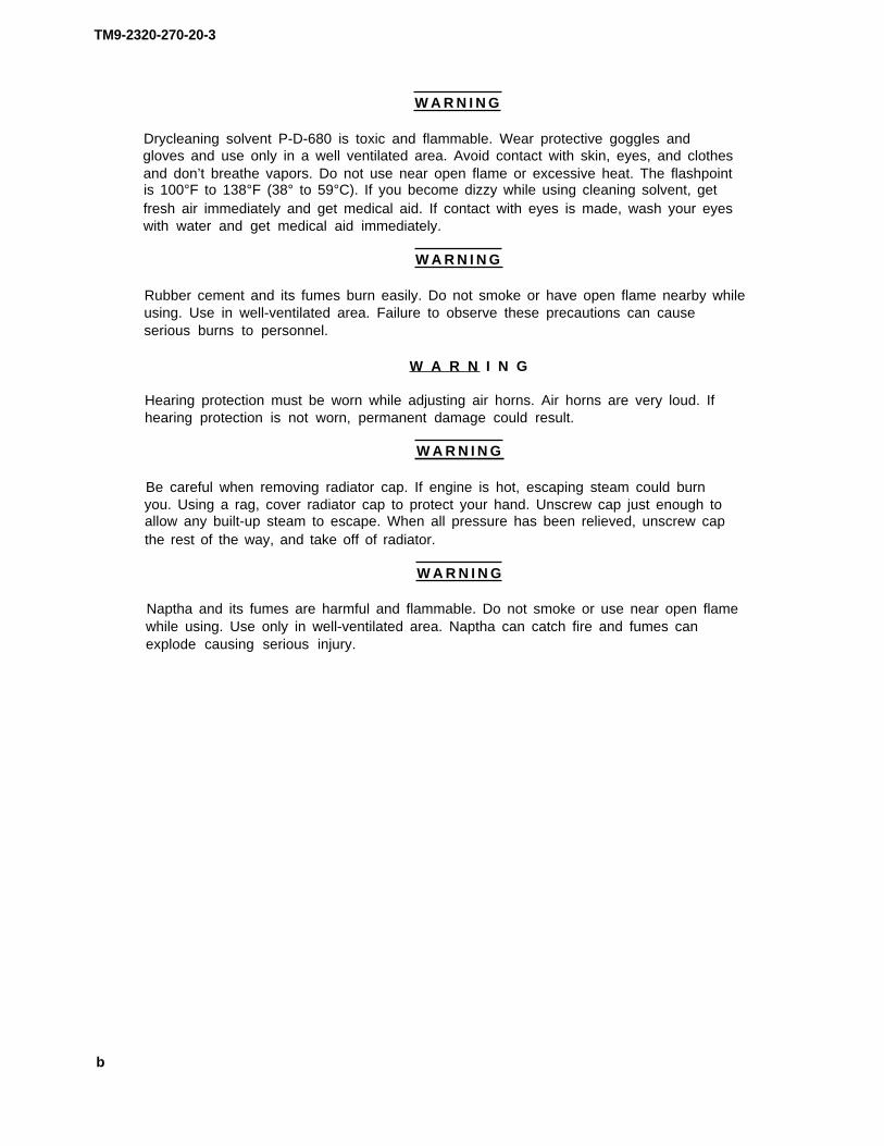
40. Two fittings (1)and (2)
41. Trailer brakehandle assembly (4)
42.
43. Air lines (7),(8), and (9)
44. Connector (11)
Two inserts (3)
Air line 27 (5)
Air line 663 (6)
Tie wrap (10)
Horn buttonwire (12)
Using rubber hammer, tap in.
a. Lube end lightiy with soap and push in.b. Screw on and tighten using 5/8-inch and
9/16-inch open-end wrenches.
a. Lube end lightiy with soap and push in.b. Screw on and tighten using 5/8-inch and
9/16-inch open-end wrenches.
Using long-nose pliers, put on.
Plug in.
T A 2 4 0 6 0 3
4-952

DASH BRACE - CONTINUED
N O T E
FOLLOW-ON MAINTENANCE:
1. Install left hood side panel and close hood (TM 9-2320-270-10).2. Check for leaks (page 4-1).3. Connect battery ground cable (page 4-444).4. Check operation (TM 9-2320-270-10).
TASK ENDS HERE
STEERING SHAFT GREASE FITTING
This task covers:
Replacement (page 4-954)
INITIAL SETUP
Tools Personnel Required
Wrench, open-end, 5/16-inch One
Materials/Parts Equipment Condition
Grease fitting, steering shaft Left hood side panel removed(TM 9-2320-270-10).
4-953
TM9-2320-270-20-3

TM9-2320-270-20-3
STEERING SHAFT GREASE FITTING - CONTINUED
ACTION
LOCATION ITEM REMARKS
REPLACEMENT
1. Steering shaft (1) a. Using wrench, unscrew and take out.b. Get rid of.
2. Screw in and tighten using wrench.
Grease fitting (2)
New greasefitting (2)
N O T E
FOLLOW-ON MAINTENANCE:
1. Lubricate (LO 9-2320-270-12).2. Install left hood side panel (TM 9-2320-270-10).
TASK ENDS HERE
T A 2 4 0 6 0 4
4-954

TM9-2320-270-20-3
WHEEL TO BOOSTER DRAG LINK
This task covers:
a. Inspection (page 4-955) e. Cleaning (page 4-958)b. Adjustment (page 4-956) f. Inspection/Replacement (page 4-958)c. Removal (page 4-956) g. Assembly (page 4-959)d. Disassembly (page 4-958) h. Installation (page 4-960)
INITIAL SETUP
Tools
Extension, 1/2- inch drive, 3-inchHammer, machinist’s ball-peen,
2-poundHandle, ratchet, 1/2-inch drivePliers, long-nose, roundRetrieving tool, magneticScrewdriver bit, 1 13/16-inch,
1/2-inch driveSocket, 5/8-inch, 1/2-inch driveWoodblockWrench, adjustableWrench, box, 5/8-inchWrench, open-end, 7/16-inchWrench, pipe, 14-inch
Materials/Parts
Cotter pin, spring seat plugGrease (LO 9-2320-270-12)Nut, self-locking, steering booster clampRope (item 11, appendix C)
Personnel Required
One
ACTIONLOCATION ITEM REMARKS
INSPECTION
1. Truck Park on level surface with wheels positionedstraight ahead (TM 9-2320-270-10).
4-955

TM9-2320-270-20-3
WHEEL TO BOOSTER DRAG LINK - CONTINUED
ACTIONLOCATION ITEM REMARKS
INSPECTION – CONTINUED
2. Steering arm (1) Drag link (2) Move forward and backward and side toside.
Drag link should be able to rock onaxis of steering arm ball, but thereshould be no looseness. If anylooseness, go to step 3.
Check for correct placement and security.Tighten any loose parts. Replace anymissing or damaged parts.
3. Drag link (2) to Locking nut (4),steering booster (3) screw (5),
and nut (6)
ADJUSTMENT
N O T E
Looseness between drag link and steering arm can be taken up by adjustment. If loose-ness cannot be taken out by the adjustment, go to removal.
4. Drag link (2) to Cotter pin (8) a.spring seat plug (7) b.
5. Drag link (2) Spring seat plug (7) a.
b.
6. Drag link (2) to New cotter pin (8) a.spring seat plug (7) b.
c.
REMOVAL
CAUTION
Using pliers, take out.Get rid of.
Using screwdriver bit and handle,tighten.Back off just enough so slot linesup with holes.
Put in.Note if spring seat plug is screwed inso far that cotter pin (8) missesslot (9).
If cotter pin is above slot,repair drag link.
Using pliers, put in and bend backover plug (7).
If steering booster is not supported when drag link is removed, damage to steeringbooster may result.
4-956

TM9-2320-270-20-3
WHEEL TO BOOSTER DRAG LINK - CONTINUED
LOCATION ITEMACTION
REMARKS
7.
8. Drag link (2) tosteering booster (3)
Steering booster (3)
Locknut (4)
Using rope, support and tie to frame.
Using adjustable wrench, unscrew part way.
9. Steering booster Screw (5) and self- a. Using 5/8-inch box wrench, 5/8-inchclamp (9) locking nut (6) socket, and handle, unscrew and take
out.b. Get rid of self-locking nut (6).
TA240605
4-957
NOTE: SHOWN WITH BATTERY BOX REMOVED FOR CLARITY.

TM9-2320-270-20-3
WHEEL TO BOOSTER DRAG LINK - CONTINUED
ACTION
LOCATION ITEM REMARKS
REMOVAL – CONTINUED
10. Drag link (1) to Cotter pin (3)
spring seat plug (2)
11. Spring seatplug (2)
12. Outer bearingseat (4)
13. Steering arm Drag link (1)
ball (5)
14. Steering booster (6) Drag link (1)
DISASSEMBLY
15. Drag link (1) Inner bearing seat(7), spring (8),spring seat (9), andspacer (10)
16.
17.
Locknut (11)
Grease fitting (12)
CLEANING
18. All parts
inspection/REPLACEMENT
19. All parts
a. Using pliers, take out.b. Get rid of.
Using screwdriver bit, extension, andhandle, unscrew and take out.
Using magnetic retrieving tool, take out.
Lift off.
Using pipe wrench, unscrew and take out.
Tap drag link (1) on woodblock and takeout.
Using adjustable wrench, unscrew and takeoff.
Using 7/16-inch wrench, unscrew and takeout.
Clean according to general maintenanceinstructions (page 4-1).
Inspect according to general maintenanceinstructions (page 4-1).
4-958

TM9-2320-270-20-3
WHEEL TO BOOSTER DRAG LINK - CONTINUED
LOCATION ITEMACTION
REMARKS
ASSEMBLY
20. Drag link (1)
21.
22.
Locknut (11)
Grease fitting (12)
Spacer (10), springseat (9), spring(8), and innerbearing seat (7)
Screw on all the way to front of threads.
Screw in and tighten using 7/16-inchwrench.
Coat with clean grease and put in.
TA240606
4-959

TM9-2320-270-3
WHEEL TO BOOSTER DRAG LINK - CONTINUED
ACTION
LOCATION ITEM REMARKS
INSTALLATION
23. steeringbooster (1)
24. Steering armball (3)
25. Drag link (2)
26.
27. Drag link (2) tospring seat plug (5)
Drag link (2) Put in place and using pipe wrench,screw in until it bottoms.
Drag link (2) a. Unscrew until it fits over steeringarm ball (3).
b. Put on.
Outer bearing Coat with grease and put in.
seat (4)
Spring seat a. Screw in and tighten using screwdriver
plug (5) bit extension and handle.b. Back off until slot alines with cotter
pin holes.
New cotter pin (6) Using pliers, put in.
TA240607
4-960

TM9-2320-270-20-3
WHEEL TO BOOSTER DRAG LINK - CONTINUED
ACTIONLOCATION ITEM REMARKS
28. Steering booster Screw (8) and newclamp (7) self-locking
nut (9)
29. Drag link (2) to Locknut (10)steering boosterclamp (7)
30. Steering boosterassembly (11)
Screw in and tighten using box wrench,5/8-inch socket, and handle.
Screw on and tighten using adjustablewrench.
Take off rope.
NOTE:SHOWN WITH BATTERY BOXREMOVED FOR CLARITY.
N O T E
FOLLOW-ON MAINTENANCE:
1. Lubricate (LO 9-2320-270-12).2. Check operation (TM 9-2320-270-10).
TASK ENDS HERE
TA240608
4-961

TM9-2320-270-20-3
PITMAN ARM TO BOOSTER DRAG LINK
This task covers:
a. Inspection (page 4-962) e.b. Adjustment (page 4-963) f.c. Removal (page 4-964) 9.d. Disassembly (page 4-965) h.
Cleaning (page 4-965)Inspection/Replacement (page 4-965)Assembly (page 4-965)Installation (page 4-966)
INITIAL SETUP
Tools Materials/Parts
Hammer, plastic Cotter pin, boster ball studHandle, ratchet, 1/2-inch drive Cotter pin, spring seat plugKey, socket head screw, 3/16-inch Drag link dust seal and felt kitPliers, long-nose, round Grease (LO 9-2330-270-1 2)Puller, mechanical, gear and bearingRetrieving tool, magnetic Personnel RequiredScrewdriver bit, 13/6-inch,
1/2-inch drive OneSocket, 1 1/4-inch, 1/2-inch driveWoodblockWrench, open-end, 7/16-inch
ACTIONLOCATION ITEM REMARKS
INSPECTION
1. Truck Park on level surface with wheels positionedstraight ahead (TM 9-2320-270-10).
2. Pitman arm (1) Drag link (2) Move
3. Steering booster (3) Drag link (2) and Moveball stud (4)
forward and backward, up and down.Drag link should be able to rockback and forth on pitman arm ball,but there should be no looseness.if any looseness, go to step 3.
right and left, up and down.Drag link and ball stud should beable to rock back and forth on bailstud seats, but there should be nolooseness. if any looseness, notifydirect support maintenance.
4-962

TM9-2320-270-20-3
PITMAN ARM TO BOOSTER DRAG LINK - CONTINUED
ACTIONLOCATION ITEM REMARKS
ADJUSTMENT
N O T E
4.
5.
6.
Looseness between drag link and pitman arm can be taken up by adjustment. If loose-ness cannot be taken out by adjustment, go to removal.
Drag link (2) to Cotter pin (6)spring seat plug (5)
Drag link (2) Spring seat plug (5)
Drag link (2) to New cotter pin (6)spring seat plug (5)
a.b.
a.
b.
a.b.
c.
Using pliers, take out.Get rid of.
Using screwdriver bit and handle,tighten.Back off just enough so slot linesup with cotter pin holes.
Put in.Note if spring seat plug is screwed inso far that cotter pin (6) missesslot.
If cotter pin is above slot,repair drag link.
Using pliers, spread and bend back.
TA240609
4-963

TM9-2320-270-20-3
PITMAN ARM TO BOOSTER DRAG LINK - CONTINUED
ACTION
LOCATION ITEM REMARKS
REMOVAL
7. Drag link (1) to Cotter pin (3)
steering boosterball stud (2)
8. Nut (4)
9. Steering booster Drag link (1)
ball stud (2)
10. Drag link (1) to Cotter pin (6)spring seatplug (5)
11. Drag link (1) Dust seal (7)
12. Spring seat plug (5)
13. Outer bearingseat (9)
14. Pitman arm Drag link (1)
ball (10)
15.
DISASSEMBLY
16. Drag link (1)
17.
18.
Dust seal (7)
a. Using pliers, take out.b. Get rid of.
Using 1 1/4-inch socket and handle, un-screw and take out.
Using puller, pull off.
a. Using pliers, take out.b. Get rid of.
Using pliers, untie two ties (8) andtake off.
Using screwdriver bit and handle, unscrewand take out.
Using magnetic retrieving tool, take out.
Pull off.
a. Take off.b. Get rid of.
Inner bearing seat Tap drag link (1) on woodblock and take
(11), spring (12), out.and spring seat (13)
Grease fitting (14) Using 7/16-inch wrench, unscrew and takeout.
Plug (15) Using key, unscrew and take out.
4-964

TM9-2320-270-20-3
PITMAN ARM TO BOOSTER DRAG LINK - CONTINUED
ACTIONLOCATION ITEM REMARKS
CLEANING
19. All parts Clean according to general maintenanceinstructions (page 4-1).
inspection/REPLACEMENT
20. All parts Inspect according to general maintenanceinstructions (page 4-1).
ASSEMBLY
21. Drag link (1) Grease fitting (14) Screw in and tighten using 7/16-inchwrench.
22.
23.
Plug (15) Screw in and tighten using key.
Spring seat (13), Coat with clean grease and put in.spring (12), andinner bearingseat (11)
TA24061O
4-965

TM9-2320-270-20-3
PITMAN ARM TO BOOSTER DRAG LINK - CONTINUED
ACTION
LOCATION ITEM REMARKS
INSTALLATION
24. Pitman arm ball (1)
25.
26. Booster ballstud (4)
27. Drag link (3)
28.
29. Booster ballstud (4)
New dust seal (2)
Drag link (3)
Drag link (3)
Outer bearingseat (5)
Spring seatplug (6)
Drag link (3)
Put on.
Place in position.
Put on.
Coat with grease and put in.
Screw in enough to keep drag link inplace.
With plastic hammer, tap lightly justahead of ball stud (4) to seat.
TA240611
4-966

TM 9-2320-270-20-3
PITMAN ARM TO BOOSTER DRAG LINK - CONTINUED
LOCATIONACTION
ITEM REMARKs
INSTALLATION – CONTINUED
30. Drag link (3) tobooster ball stud (4)
31.
32. Drag link (3)to pitman arm (9)
33.
34. Drag link (3)
35. Dust seal (2)
Nut (7)
New cotter pin (8)
Spring seatplug (6)
New cotter pin (10)
Dust seal (2)
Two metal ties (11)
a. Screw on and tighten using 1 1/4-inch socket and handle.
b. Back off just enough to put in cotterpin (8).
Put in and using pliers, bend back.
a. Using screwdriver bit and handle,tighten.
b. Back off just enough to put in cotterpin (10).
Put in and using pliers, bend back.
Wrap around.
Using pliers, secure.
NOTE
FOLLOW-ON MAINTENANCE: Lubricate (LO 9-2320-270-12) and check operation(TM 9-2320-270-10).
TASK ENDS HERE
TA240612
4-967

TM9-2320-270-20-3
TIE ROD
This task covers:
a. Removal (page 4-968) e. Assembly (page 4-970)b. Disassembly (page 4-969) f. Installation (page 4-971)c. Cleaning (page 4-970) g. Alinement (page 4-972)d. Inspection/Replacement (page 4-970)
INITIAL SETUP
Tools
Chisel, 1/2-inchGage, front wheel alinementHammer, machinist’s ball-peen,
2-poundHandle, ratchet, 1/2-inch driveHandle, ratchet, 3/4-inch drivePliers, long-nose, roundPuller, mechanical, gear and bearingSocket, 5/8-inch, 1/2-inch driveSocket, 15/16-inch, 1/2-inch driveSocket, 15/16-inch, 3/4-inch driveWrench, box, 15/16-inchWrench, open-end, 7/16-inchWrench, pipe, 14-inch
Tools – Continued
Wrench, torque, 3/4-inch drive
Materials/Parts
Cotter pin, tie rod end nut to steering arm(two required)
Lockwasher, tie rod clamp screw (fourrequired)
Personnel Required
One
ACTIONLOCATION ITEM REMARKS
REMOVALN O T E
Steps used to disconnect both right and left tie rod ends are the same. Left tie rod end isshown.
1.
2. Left tie rod end(1) to steeringarm (2)
3.
4. Left steeringarm (2)
Truck Park on level surface with wheels positionedstraight ahead (TM 9-2320-270-1 O).
Cotter pin (3) a. Using pliers, take out.b. Get rid of.
Nut (4) and Using 15/16-inch socket and handle withwasher (5) 3/4-inch drive, unscrew and take off.
Left tie rod Using puller, 5/8-inch socket, and handleend (1) with 1/2-inch drive, press out.
4-968

TM9-2320-270-20-3
TIE ROD - CONTINUED
ACTIONLOCATION ITEM REMARKS
5. Right steering Right tie rod end Repeat steps 2 thru 4.arm (6) (7) and tie rod (8)
6. Left tie rod end (1) Spring (9), washer Take off.(10), spacer (11),and washer (12)
DISASSEMBLY
7. Two tie rod ends Four screws (13), a. Using 15/16-inch box wrench, 15/16-(1) and (7) to tie nuts (14), and inch socket, and handle with 1/2-rod (8) lockwasher (15) inch drive, unscrew and take out.
b. Get rid of Iockwashers (15).
8. Tie rod (8) Tie rod ends (1) Using chisel and ball-peen hammer, spreadand (7) tie rod ends.
Do not drive chisel into threads.
9. Left tie rod Unscrew clockwise and take off.end (1)
10. Right tie rod Unscrew counterclockwise and take off.end (7)
TA240613
4-969

TM9-2320-270-20-3
TIE ROD - CONTINUED
ACTION
LOCATION ITEM REMARKS
DISASSEMBLY – CONTINUED
N O T E
Do not remove tie rod end grease fittings unless damaged.
Step is the same for right or left tie rod end grease fitting. Left tie rod end is shown.
11. Left tie rod end (1)
CLEANING
12.
inspection/REPLACEMENT
13.
ASSEMBLY
All parts
Grease fitting (2) Using 7/16-inch wrench, unscrew and takeout.
Clean according to general maintenanceinstructions (page 4-1).
All parts Inspect according to general maintenanceinstructions (page 4-1).
N O T E
Left tie rod end has left hand threads, right tie rod end has right hand threads.
Skip step 14 if grease fitting was not removed.
14. Tie rod ends (1) Grease fitting (2) Screw in and tighten using 7/16-inch
and (3) wrench.
15. Tie rod ends (1) Four screws (5), Screw in but do not tighten.
and (3) to tie new Iockwashers (6),
rod (4) and nuts (7)
16. Left tie rod a. Using ball-peen hammer and chisel,
end (1) spread enough so it can be screwed on.b. Screw on counterclockwise.
17. Tie rod (4) Right tie rod Screw on clockwise.
end (3)
4-970

TM9-2320-270-20-3
TIE ROD - CONTINUED
LOCATION ITEMACTION
REMARKS
INSTALLATION
18. Left tie rod end (1) Washer (8), spacer(9), washer (10),and spring (11)
19. Steering arm (12) Tie rod (4) andleft tie rodend (1)
20. Tie rod end (1) to Washer (13) andsteering arm (12) nut (14)
21. Right steering Tie rod (4) andarm (15) right tie rod
end (3)
Put in place.
a. Lift tie rod and guide into hole.b. Lift up.
Screw on but do not tighten.
Repeat steps 18 through 20 to put in.
TA240614
4-971

TM9-2320-270-20-3
TIE ROD - CONTINUED
ACTION
ITEM REMARKSLOCATION
INSTALLATION – CONTINUED
22. Tie rod ends (1 andTwo nuts (5) a.
2) to steering arms b.(3 and 4)
c.
d.
23.
ALINEMENT
24.
25.
26.
Using 15/16-inch socket and handlewith 3/4-inch drive, tighten.Using 15/16-inch socket and torquewrench with 3/4-inch drive, tighten to160 to 180 foot pounds (223.7 to244.1 N·m).Check to see if hole lines up withslots.If holes do not line in, tighten justenough to line up.
Two new cotter Using pliers, put in.
pins (6)
Tie rod Lubricate (LO 9-2320-270-20).
Tires Check air pressure of all tires(TM 9-2320-270-10).
Front wheels (7) Using wheel alinement gage, check frontwheel toe-in.
Toe-in should be 1/8-inch (3.17millimeter). If toe-in is correct,continue at step 30.
N O T E
If tie rod has just been installed, skip steps 27 and 28.
27. Tie rod endsFour clamp screws Using 15/16 box wrench, 15/16-inch
(1 and 2) (9) and nuts (10) socket, and handle with 1/2-inch drive,
to tie rod (8)unscrew part way.
28.Tie rod ends (1) Using ball-peen hammer and cold chisel,
and (2) spread clamp end of tie rod ends enough toturn tie rod (8).
4-972

TM9-2320-270-20-3
TIE ROD - CONTINUED
LOCATION ITEMACTION
REMARKS
20. Front wheels (7) Tie rod (8) Using wheel alinement gage and pipewrench, adjust toe-in to 1/8-inch (3.17millimeter).
Looking towards the right tie rodend, turning tie rod clockwiseincreases toe-in, turning tierod counterclockwise decreasestoe-in.
30. Tie rod ends (1) Four clamp screws Using 15/16-inch box wrench, 15/16-inchand (2) (9) and nuts (10) socket, and handle with 1/2-inch drive.
tighten.
TA240615
4-973

TM9-2320-270-20-3
PITMAN ARM STOP BRACKET
This task covers:
Adjustment (page 4-974)
INITIAL SETUP
ToolsPersonnel Required
Gage, thicknessTwo
Wrench, open-end, 3/4-inch(two required)
ACTION
ITEM REMARKSLOCATION
ADJUSTMENT
CAUTION
If pitman arm stopscrews are not adjusted correctly, steering booster will be damaged.
1. Engine Start (TM 9-2320-270-10).
W A R N I N G
Do not get between wheels and fender, or between other moving and stationary parts,while assistant is turning wheels. There is no clearance for personnel in these areaswhen turning vehicle.
Hearing protection must be worn while working under truck with engine running to pre-vent possible ear injury.
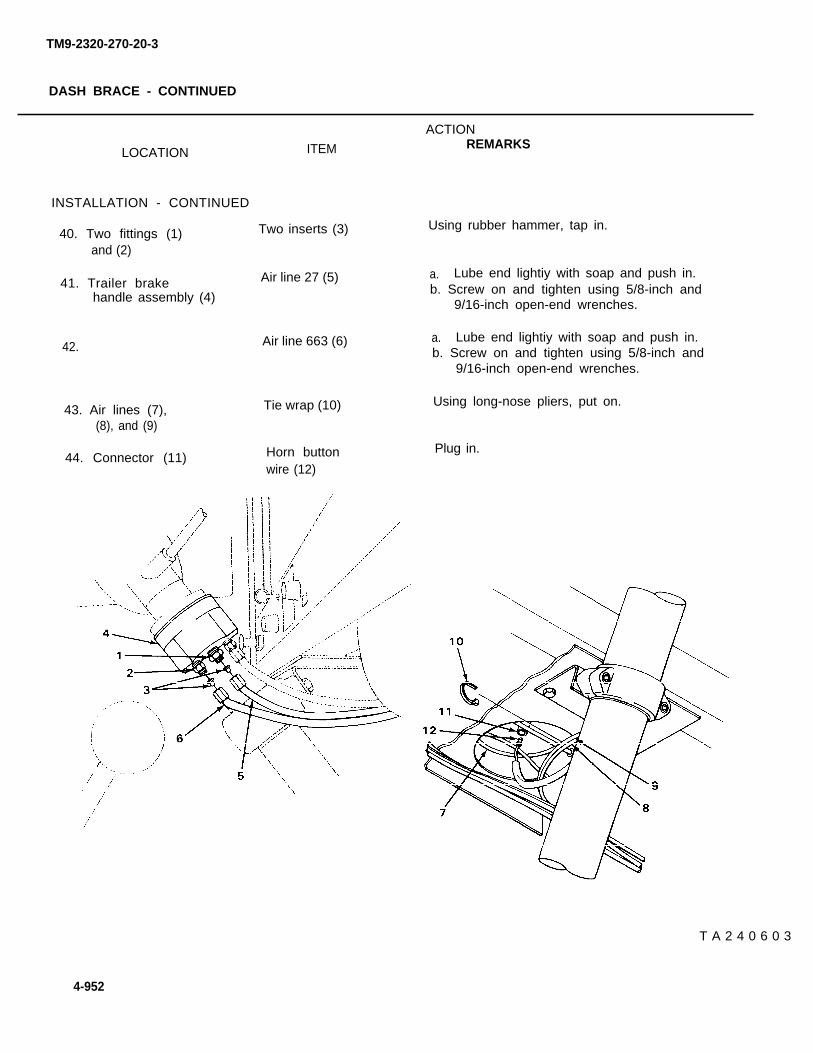
2. Right side of frontaxle (1)
Right front spindlestopscrew (2) andright front axleball (3)
a.
b.
c.
Position 1/16-inch (1.59 mm)thickness gage between stopscrew (2)and axle ball (3).Have assistant slowly turn steeringwheel left until stopscrew (2) isstopped by thickness gage.Have assistant hold steering in thisposition.
4-974

TM9-2320-270-20-3
PITMAN ARM STOP BRACKET - CONTINUED
LOCATION ACTIONITEM REMARKS
3. Pitman arm stop Front pitman arm Using two 3/4-inchbracket (4) stopscrew (5) and unscrew part way.locknut (6)
4. Inner nut (7) andStopscrew (5)
Using two 3/4-inch open-end wrenches,tighten stopscrew (5).
Locknut (6) Using two 3/4-inch open-end wrenches,tighten.
TA240616
4-975
5 .
open-end wrenches,

TM9-2320-270-20-3
PITMAN ARM STOP BRACKET- CONTINUED
ACTIONLOCATION ITEM REMARKS
ADJUSTMENT – CONTINUED
W A R N I N G
Do not get between wheels and fender, or between other moving and stationary parts,while assistant is turning wheels. There is no clearance for personnel in these areaswhen turning vehicle.
Hearing protection must be worn while working under truck with engine running toprevent possible ear injury.
6. Left side of front Left front spindle a. Position 1/16-inch (1.59 mm) thick-axle (1) stopscrew (2) and ness gage between ball (3) and stop-
right axle ball (3) screw (2).b. Have assistant slowly turn steering
wheel right until stopscrew (2)is stopped by thickness gage.
c. Have assistant hold steering in thisposition.
7. Pitman arm stop Rear pitman armbracket (4) stopscrew (5)
and locknut (6)
8. Inner nut (7) andstopscrew (5)
9. Locknut (6)
10. Engine
Using two 3/4-inch open-end wrenches,unscrew part way.
Using two 3/4-inch open-end wrenches,tighten stopscrew (5).
Using two 3/4-inch open-end wrenches,tighten.
Shut down (TM 9-2320-270-10).
4-976
TM9-2320-270-20-3
PITMAN ARM STOP BRACKET- CONTINUED
TASK ENDS HERE
TA240617
4-977

TM9-2320-270-20-3
PITMAN ARM
This task covers:
a. Removal (page 4-978)b. Installation (page 4-979)
INITIAL SETUP
Tools Materials/Parts
Handle, ratchet, 1/2-inch drive Cotter pin, drag link to spring seat plugPliers, long-nose, round Kit, drag link grease sealPuller, mechanical Lockwasher, pitman arm clamp screwnutRetrieving tool, magneticScrewdriver bit, 1 13/16-inch, Personnel Required
1/2-inch driveSocket, 3/4-inch, 1/2-inch drive OneWrench, box, 3/4-inch
ACTIONLOCATION ITEM REMARKS
REMOVAL
1. Truck Park on smooth level surface with frontwheels positioned straight ahead(TM 9-2320-270-10).
2. Drag link (1) tospring seat plug (2)
3. Drag link (1)
4.
5.
6. Pitman arm (6)
7.
Cotter pin (3)
Dust seal (4)
Spring seatplug (2)
Outer bearingseat (5)
Drag link (1)
Dust seal (4)
a. Using pliers, take out.b. Get rid of.
Using pliers, take off.
Using screwdriver bit and handle, unscrewand take out.
Using magnetic retrieving tool, take out.
Pull off of pitman arm ball and supportby resting on steering arm (7).
a. Take off.b. Get rid of.
4-978

TM 9-2320-270-20-3
PITMAN ARM -CONTINUED
ACTIONLOCATION ITEM REMARKS
8. Screw (8), nut (9), a. Using 3/4-inch socket, handle, and boxand Iockwasher (10) wrench, unscrew and take out.
b. Get rid of Iockwasher (10).
9. Levershaft(11)
INSTALLATION
10. Levershaft(11)
Pitman arm (6) Using puller, pull off.
Pitman arm (6) a. Aline index marks and put on.b. Using plastic hammer, tap into place.
Screw (8), new Screw in and tighten using 3/4-inch socket,Iockwasher (10), handle, and box wrench.
11. Pitman arm (6)
and nut (9)
TA240618
4-979

TM 9-2320-270-20-3
PITMAN ARM - CONTINUED
ACTION
ITEM REMARKSLOCATION
INSTALLATION - CONTINUED
12. Pitman arm (1)New dust seal (2) Put on.
Drag link (3) Put on.13.
14. Drag link (3)Outer bearing Put in.
seat (4)
Spring seat a.15.
plug (5)b.
16.
17.
18.
Screw in and tighten using screwdriverbit and handle.Back off so slot alines with nearestcotter pin holes.
Put in.Using pliers, bend back.
Wrap around.Using pliers, secure.
New cotter pin (6) a.b.
Dust seal (2) a.b.
Drag link (3) Lubricate (LO 9-2320270-12).
FOLLOW-ON
TASK ENDS HERE
4-960
NOTE
MAINTENANCE: Check operation (TM 9-2320-270-10).
TA240619

STEERING GEAR
This task covers:
Adjustment (page 4-981)
INITIAL SETUP
Tools Materials/Parts
Hammer, plastic Lockwasher, pitman armHandle, ratchet, 1/2-inch drivePuller, mechanicalScrewdriver, flat-tip, 5/16-inch Personnel RequiredSocket, deep, 3/4-inch, 1/2-inch
drive TwoWrench, box, 3/4-inch
ACTIONLOCATION ITEM REMARKS
ADJUSTMENT
NOTE
If Ievershaft adjustment fails to remove excess play from steering gear, notify directsupport maintenance.
1. Truck Park on smooth level surface with frontwheels positioned straight ahead.
4-981
TM 9-2320-270-20-3

TM 9-2320-270-20-3
STEERING GEAR - CONTINUED
ACTIONLOCATION ITEM REMARKS
ADJUSTMENT - CONTINUED
2. Pitman arm (1) Screw (2), nut (3),and Iockwasher (4)
3. Levershaft (5) Pitman arm (1)
4.
5. Adjusting screw (8)to steering gear (9)
6. Steering gear(9)
7.
Steering wheel (7)
Locknut (10)
Adjusting screw (8)
Steering wheel (7)
8. Adjusting screw (8) Locknut (10)to steering gear(9)
a. Using socket, handle, and box wrench,unscrew and take out.
b. Get rid of Iockwasher (4).
a. Using puller, pull off.b. Support pitman arm on steering
arm (6).
With engine off, have assistant turnsteering wheel lock to lock and then backto center noting any roughness.
If there is any roughness, notifydirect support maintenance.
Using 3/4-inch socket and handle, unscrewalmost all the way.
Using screwdriver, screw in until adjust-ing screw (8) starts to tighten.
a. Have assistant turn lock to lock.There should be slight drag and noplay at center. Drag should decreaseand play increase as the steeringwheel is turned toward locks.
b. If there is no drag at center, tightenadjusting screw (8).
c. If there is heavy drag at center,loosen adjusting screw (8).
If there is still no drag at center,after tightening, and if steering isloose at center, then drag increasesand decreases, notify direct supportmaintenance.
Screw down and tighten using socket andhandle.
4-982

TM 9-2320-270-20-3
STEERING GEAR - CONTINUED
ACTIONLOCATION ITEM REMARKS
9. Steering wheel (7) a.
b.
c.
d.
e.
Have assistant turn lock to lock and seeif tightening locknut (10) has causedheavy drag at center.If there is heavy drag at center,using 3/4-inch socket and handle,loosen locknut (10).Using screwdriver, loosen adjustingscrew (1) one-quarter turn.Using 3/4-inch socket and handle,tighten locknut (10).Have assistant check drag again.
If drag is still heavy, repeat steps9b thru 9e.
TA240620
4-983

TM 9-2320-270-20-3
STEERING GEAR - CONTINUED
ACTIONLOCATION ITEM REMARKS
ADJUSTMENT - CONTINUED
10. Levershaft (1)
11. Pitman arm (2)
Pitman arm (2)
Screw (3), newIockwasher (4),and nut (5)
a. Aline index marks and put on.b. Using plastic hammer, tap in.
Screw in and tighten using socket, handle,and box wrench.
TASK ENDS HERE
TA240621
4-984

TM 9-2320-270-20-3
POWER STEERING PUMP
This task covers:
a. Removal (page 4-986) d. Inspection/Replacement (page 4-988)b. Disassembly (page 4-988) e. Assembly (page 4-989)c. Cleaning (page 4-988) f. Installation (page 4-990)
INITIAL SETUP
Tools Materials/Parts
Caps, vise jaw, brass Gasket, power steering pump to adapterDrift, brass, l/2-inch Fluid, power steering (LO 9-2320-270-12)Hammer, mac
12-ounceHammer, plasKnife, pocketKnife, puttyPan, drain
inist’s ball-peen, Lockwasher, power steering pump to adapter(two required)
tic Lockwasher, pump shaftPacking, preformed, elbow and nutShipping plugs (as required)Tape, teflon (item 22, appendix C)
Puller, mechanical, gear and bearingVise Personnel RequiredWrench, adjustableWrench, open-end, 9/16-inch OneWrench, open-end, 7/8-inch (two
required) Equipment ConditionWrench, open-end, 15/16-inchWrench, open-end, 1 1/8-inch Left side of hood open (TM 9-2320-270-10).Wrench, open-end, 1 1/4-inch
(two required)Wrench, open-end, 1 5/16-inchWrench, open-end, 1 7/16-inchWrench, open-end, 1 l/2-inchWrench, pliers
4-985

TM 9-2320-270-20-3
POWER STEERING PUMP - CONTINUED
ACTIONLOCATION ITEM REMARKS
REMOVAL
1. Power steeringreservoir (1)
2.
3. Elbow (4)
4. Elbow (6)
5. Elbow (8)
6. Power steeringpump (3) toadapter (10)
7. Adapter (10)
8. Drive gear (13) ordrive plate (14)
9. Adapter (10) orpower steeringpump (3)
Drainplug (2)
Power steeringpump (3)
Inlet hose (5)
Return hose (7)
Pressure hose (9)
Two capscrews(11)and Iockwashers (12)
Power steeringpump (3)
Coupling (15)
Gasket (16)
a. Place drain pan underneath.b. Using 9/16-inch wrench, unscrew and
take out.c. Allow fluid to drain and get rid of
fluid (page 4-1).
Put drain pan underneath.
Using 1 7/16-inch and 1 1/2-inchwrenches, unscrew and take off.
Using two 1 1/4-inch wrenches, unscrewand take off.
Using 15/16-inch and 7/8-inch wrenches,unscrew and take off.
a. Using 9/16-inch wrench, unscrew andtake out.
b. Get rid of lockwashers (12).
Take off.
Take out.
a. Using putty knife, take off.b. Get rid of.c. Remove drain pan and get rid of
fluid (page 4-1).
4-986

TM 9-2320-270-20-3
POWER STEERING PUMP - CONTINUED
TA240622
4-987

TM 9-2320-270-20-3
POWER STEERING PUMP - CONTINUED
ACTIONLOCATION ITEM REMARKS
DISASSEMBLY
10.
11. Reducer (2)
12. Power steeringpump (1)
13.
14.
15. Nut (6)
16. Power steering pumpshaft (8)
17.
18.
CLEANING
19.
lNSPECTION/REPLACEMENT
20.
Power steeringpump (1)
Elbow (3)
Reducer (2)
Elbow (4)
Elbow (5) andnut (6)
Packing (7)
Nut (9) and lock-washer (10)
Drive gear (11)
Key (12)
All parts
All parts
Secure in vise with brass jaw caps.
Using adjustable and 1 5/16-inchwrenches, unscrew and take out.
Using adjustable wrench, unscrew and takeout.
Using 1 l/8-inch wrench, unscrew and takeout.
a. Using two 7/8-inch wrenches, unscrewpart way.
b. Using 7/8-inch wrench, unscrew andtake out.
a. Using pocket knife, take out.b. Get rid of.
a. Using 11/4-inch wrench and plierswrench, unscrew and take off.
b. Get rid of Iockwasher (10).
Using puller, pull off.
a. Using ball-peen hammer and brassdrift, tap out.
b. Remove pump (1) from vise.
Clean according to general maintenanceinstructions (page 4-l).
Inspect according to general maintenanceinstructions (page 4-l).
4-988

TM 9-2320-270-20-3
POWER STEERING PUMP - CONTINUED
ACTIONLOCATION ITEM REMARKS
ASSEMBLY
21. Power steering Key (12) a. Secure pump (1) in vise with brass jawpump shaft (8) caps.
b. Using plastic hammer, tap in.
22. Position in vise shaft (8), up.
23.
24.
25.
26.
Power steeringpump (1)
Drive gear (11)
Nut (9)
a.b.
a.
b.
Put on.Using plastic hammer, tap on until twoor three shaft threads are showning.
Using pliers and 1 1/4-inch wrenches,screw on.Using pliers and 1 1/4-inch wrenches,unscrew and take off.
New Iockwasher (10) Put on.
Nut (9) Screw on and tighten usingand pliers wrenches.
1 1/4-inch
TA240623
4-989

TM 9-2320-270-20-3
POWER STEERING PUMP - CONTINUED
ACTIONLOCATION ITEM REMARKS
ASSEMBLY – CONTINUED
27. Nut (1)
28. Power steeringpump (3)
29.
30.
31. Reducer (6)
INSTALLATION
32.
33. Drive gear (8)
34. Power steeringpump (3)
35. Drive plate (11)
36. Adapter (12)
37. Power steering pump(3) to adapter (12)
38. Elbow (4)
39. Elbow (5)
New Packing (2)
Elbow (4) andnut (1)
Elbow (5)
Reducer (6)
Elbow (7)
Power steeringpump (3)
Coupling (9)
New gasket (10)
Coupling (9)
Power steeringpump (3)
Two screws (13) andnew Iockwashers (14)
Pressure hose (15)
Return hose (16)
Put in place.
a.
b.
a.
b.
a.
b.
a.
b.
Wrap threads with teflon tape(page 4-1).Screw in and tighten using two 7/8-inchwrenches.
Wrap threads with teflon tape(page 4-1).Screw in and tighten using 1 1/8-inchwrench.
Wrap threads with teflon tape(page 4-1).Screw in and tighten using adjustablewrench.
Wrap threads with teflon tape(page 4-1).Screw in and tighten using 1 5/16-inchwrench.
Set on end, shaft up.
Put on.
Put in place.
Put pump (3) in place and engage teeth.
Push into place.
Screw in and tighten using 9/16-inchwrench.
Screw on and tighten using 15/16-inchand 7/8-inch wrenches.
Screw on and tighten using 1 1/4-inchand 1 1/4-inch wrenches.
4-990

TM 9-2320-270-20-3
POWER STEERING PUMP - CONTINUED
ACTIONLOCATION ITEM REMARKS
40. Elbow (7) Pressure hose (17) Screw on and tighten using 1 7/16-inchand 1 1/2-inch wrenches.
TA240624
4-991

TM 9-2320-270-20-3
POWER STEERING PUMP - CONTINUED
ACTIONLOCATION ITEM REMARKS
INSTALLATION - CONTINUED
41. Power steering Drainplug (2)reservoir (1)
42. Oil level gage (3)
43. Power steeringreservoir (1)
44. Engine
45.
46.
47.
Steering wheel
Oil level gage (3)
Engine
Screw in and tighten using 9/16-inchwrench.
Unscrew and take out.
Fill with fluid to full mark on gage (3).
a. Start and idle for 10 minutes(TM 9-2320-270-10).
b. Check for leaks.
Turn lock-to-lock four times.
a. Check fluid level and add fluid ifnecessary.
b. Put in and tighten.
Shut down (TM 9-2320-270-10).
TA240625
4-492

TM 9-2320-270-20-3
POWER STEERING PUMP - CONTINUED
NOTE
FOLLOW-ON MAINTENANCE: Close hood (TM 9-2320-270-10).
TASK ENDS HERE
RESERVOIR TO BATTERY BOX BRACKET HOSE
This task covers:
a. Removal (page 4-994) c. Inspection/Replacement (page 4-996)b. Cleaning (page 4-996) d. Installation (page 4-996)
INITIAL SETUP
Tools
Handle, ratchet, 3/8-inch drivePan, drainPliers, diagonal cuttingSocket, 7/16-inch, 3/8-inch driveViseWrench, box, 7/16-inchWrench, open-end, 9/16-inchWrench, open-end, 7/8-inchWrench, open-end, 15/16-inchWrench, open-end, 1 1/8-inchWrench, open-end, 1 1/4-inch (two
required)Wrench, pipe, 1/2- to 1 1/2-inch
Materials/Parts
Fluid, power steering (LO 9-2320-270-12)Lockwasher, loop clamp to fenderString (item 17, appendix C)Tape, teflon (item 22, appendix C)Wrap, tie (item 24, appendix C)
Personnel Required
One
Equipment Condition
Left side of hood open (TM 9-2320-270-10).
4-993

TM 9-2320-270-20-3
RESERVOIR TO BATTERY BOX BRACKET HOSE - CONTINUED
ACTION .
LOCATION ITEM REMARKS
REMOVAL
NOTE
Tag hoses according to general maintenance instructions (page 4-1).
1. Power steeringreservoir (1)
2. Bulkheadfitting (3)
3. Loop clamp (5)to fender (6)
4. Hoses (4) and (11)
5.
6. Reducer (13)
7. Pipe tee (14)
8. Elbow (15)
9. Pipe tee (14)
10. Power steeringreservoir (1)
Drainplug (2)
Hose (4)
Screw (7), nut (8),lockwasher (9),and washer (10)
Loop clamp (5)
Two tie wraps (12)
Hose (4)
R e d u c e r
Hose to powersteering pump (16)
Elbow (15)
Pipe tee (14)and nipple (17)
a.b.
c.
a.b.
c .
a.
b.
Place drain pan underneath.Using 9/16-inch wrench, unscrew andtake out.Allow fluid to drain and get rid offluid (page 4-1).
Place drain pan underneath.Using 15/16-inch and 7/8-inchwrenches, unscrew and take off.Drain and get rid of fluid(page 4-1).
Using 7/16-inch wrench, socket, andhandle, unscrew and take out.Get rid of lockwasher (9).
Spread and take off.
a. Using cutting pliers, cut and take off.b. Get rid of.
Using two 15/16-inch wrenches, unscrewand take out.
Using 7/8-inch and pipe wrenches,unscrew and take out.
a. Using two 1 1/4-inch wrenches, un-screw and take off.
b. Using string, tie hose out of the way.
Using 1 1/8-inch wrench, unscrew and takeout.
Using pipe wrench, unscrew and take off.
4-994

TM 9-2320-270-20-3
RESERVOIR TO BATTERY BOX BRACKET HOSE - CONTINUED
LOCATION ITEMACTION
REMARKS
NOTE
Do not remove nipple usless inspection shows need for replacement.
Pipe tee (14) Nipple (17) a. Secure pipe tee (14) in vise.b. Using pipe wrench, unscrew and take
out.C. Get rid of.
11.
TA240626
4-995

TM 9-2320-270-20-3
RESERVOIR TO BATTERY BOX BRACKET HOSE - CONTINUED
ACTIONLOCATION ITEM REMARKS
CLEANING
12.
lNSPECTION/REPLACEMENT
13.
INSTALLATION
14. Pipe tee (1)
15. Power steeringreservoir (3)
16. Pipe tee (1)
17.
18. Elbow (4)
19. Reducer (5)
20. Hose (6) and (7)
21. Fender (9)
All parts
All parts
NOTE
—
Clean according to general maintenanceinstructions (page 4-1).
Inspect according to general maintenanceinstructions (page 4-1).
Skip step 14 if nipple was not removed.
Nipple (2) a. Wrap threads with teflon tape(page 4-1).
b. Screw in.
Pipe tee (1) and Screw in and tighten using pipe wrench.
Reducer (5)
Hose to powersteering pump (6)
nipple (2)
Elbow (4) a.
b.
a.
b.
a.b.
a.b.
Hose (7)
Loop clamp (8)
Screw (10)
Wrap threads with teflon tape(page 4-1).Screw in and tighten using 1 1/8-inchwrench.
Wrap threads with teflon tape(page 4-1).Screw in and tighten using 7/8-inchand pipe wrenches.
Untie and place in position.Screw on and tighten using two 1 1/4-inch wrenches.
Route hose (7) into place.Screw on and tighten using 7/8-inchand 15/16-inch wrenches.
Put on and close.
Put in place.
4-996

TM 9-2320-270-20-3
RESERVOIR TO BATTERY BOX BRACKET HOSE - CONTINUED
ACTIONLOCATION ITEM REMARKS
22. Screw (10) Loop clamp (8), Screw on and tighten using 7/16-inchwasher (11), new wrench, socket, and handle.lockwasher(12),and nut (13)
23. Bulkheadfitting (14)
24. Hoses (6) and (7)
Hose (6)
Two new tiewraps (15)
Screw on and tighten using 7/8-inchand 15/16-inch wrenches.
Using slip-joint pliers, put on.
TA240627
4-997

TM 9-2320-270-20-3
RESERVOIR TO BATTERY BOX BRACKET HOSE - CONTINUED
ACTION- .
LOCATION ITEM REMARKS
INSTALLATION - CONTINUED
25. Power steering Drainplug (2)reservoir (1)
26. Oil level gage (3)
27. Power steeringreservoir (1)
28. Engine
29.
30.
31•
Steering wheel
Oil levelgage (3)
Engine
Screw in and tighten using 9/16-inchwrench.
Unscrew and take out.
Fill with fluid to full mark on gage (3).
a. Start and idle for 10 minutes(TM 9-2320-270-10).
b. Check for leaks.
Turn lock-to-lock four times.
a. Check fluid level and add fluid ifnecessary.
b. Put in and tighten.
Shut down (TM 9-2320-270-10).
4-998
TA240628

RESERVOIR TO BATTERY BOX BRACKET HOSE - CONTINUED
NOTE
FOLLOW-ON MAINTENANCE: Close left side hood (TM 9-2320-270-10).
TASK ENDS HERE
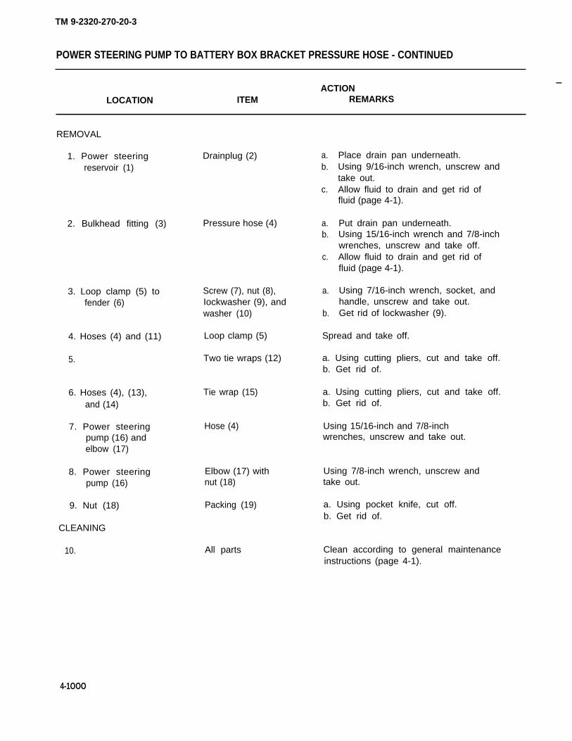
POWER STEERING PUMP TO BATTERY BOX BRACKET PRESSURE HOSE
This task covers:
a. Removal (page 4-1000) c. Inspection/Replacement (page 4-1001)b. Cleaning (page 4-1000) d. Installation (page 4-1002)
INITIAL SETUP
Tools
Handle, ratchet, 3/8-inch driveKnife, pocketPan, drainPliers, diagonal-cuttingPliers, slipjoint, straight-noseSocket, 7/16-inch, 3/6-inch driveWrench, box, 7/16-inchWrench, open-end, 9/16-inchWrench, open-end, 7/8-inch (two
required)Wrench, open-end, 15/16-inch
Materials/Parts
Fluid, power steering (LO 9-2320-270-12)Lockwasher, loop clamp to fenderPacking, preformed, elbow to power steering
pumpTape, teflon (item 22, appendix C)Wrap, tie (item 24, appendix C)
Personnel Required
One
Equipment Condition
Left side hood open (TM 9-2320-270-10).
4-999
TM 9-2320-270-20-3
TM 9-2320-270-20-3
POWER STEERING PUMP TO BATTERY BOX BRACKET PRESSURE HOSE - CONTINUED
ACTION—
LOCATION ITEM REMARKS
REMOVAL
1. Power steering Drainplug (2) a.reservoir (1) b.
c.
2. Bulkhead fitting (3) Pressure hose (4) a.b.
c.
3. Loop clamp (5) to Screw (7), nut (8),fender (6) Iockwasher (9), and
washer (10)
4. Hoses (4) and (11) Loop clamp (5)
5. Two tie wraps (12)
6. Hoses (4), (13), Tie wrap (15)and (14)
7. Power steering Hose (4)pump (16) andelbow (17)
8. Power steeringpump (16)
9. Nut (18)
CLEANING
10.
4-1OOO
Elbow (17) withnut (18)
Packing (19)
All parts
a.
b.
Place drain pan underneath.Using 9/16-inch wrench, unscrew andtake out.Allow fluid to drain and get rid offluid (page 4-1).
Put drain pan underneath.Using 15/16-inch wrench and 7/8-inchwrenches, unscrew and take off.Allow fluid to drain and get rid offluid (page 4-1).
Using 7/16-inch wrench, socket, andhandle, unscrew and take out.Get rid of lockwasher (9).
Spread and take off.
a. Using cutting pliers, cut and take off.b. Get rid of.
a. Using cutting pliers, cut and take off.b. Get rid of.
Using 15/16-inch and 7/8-inchwrenches, unscrew and take out.
Using 7/8-inch wrench, unscrew andtake out.
a. Using pocket knife, cut off.b. Get rid of.
Clean according to general maintenanceinstructions (page 4-1).

TM 9-2320-270-20-3
POWER STEERING PUMP TO BATTERY BOX BRACKET PRESSURE HOSE - CONTINUED
ACTIONLOCATION ITEM REMARKS
lNSPECTION/REPLACEMENT
11. All parts Inspect according to general maintenanceinstructions (page 4-1).
TA240629
4-1001

TM 9-2320-270-20-3
POWER STEERING PUMP TO BATTERY BOX BRACKET PRESSURE HOSE - CONTINUED
ACTIONLOCATION ITEM REMARKS
INSTALLATION
12. Nut (1)
13. Power steeringpump (3)
14. Elbow (4)
15. Hoses (5),(6), and (7)
16. Hoses (5) and (9)
17. Fender (11)
18. Screw (12)
19. Bulkheadfitting (16)
20. Hoses (5) and (9)
21. Power steeringreservoir (18)
22.
23.
24.
25.
Packing (2)
Nut (1) andelbow (4)
Hose (5)
New tie wrap (8)
Loop clamp (10)
Screw (12)
Loop clamp (10),washer (13), newIockwasher (14),and nut (15)
Hose (5)
Two new tiewraps (17)
Drainplug (19)
Oil levelgage (20)
Power steeringreservoir (18)
Engine
Steering wheel
Put in place.
a. Wrap threads with teflon tape(page 4-1).
b. Screw in and tighten using two 7/8-inch wrenches.
Screw on and tighten using 7/8-inchand 15/16-inch wrenches.
Using slip-joint pliers, put on.
Put around and close.
Put in place.
Screw on and tighten using 7/16-inchwrench, socket, and handle.
Screw on and tighten using 15/16-inchand 7/8-inch wrenches.
Using slip-joint pliers, put on.
Screw in and tighten using 9/16-inchwrench.
Unscrew and take out.
Fill
a.
b.
Turn lock-to-lock four times.
with fluid to full mark on gage (20).
Start and idle for 10 minutes(TM 9-2320-270-10).Check for leaks.
4-1002

TM 9-2320-270-20-3
POWER STEERING PUMP TO BATTERY BOX BRACKET PRESSURE HOSE - CONTINUED
ACTIONLOCATION ITEM REMARKS
26. Oil level gage (20) a. Check fluid level and add fluid ifnecessary.
b. Put in and tighten.
27. Engine Shut down (TM 9-2320-270-10).
N O T E
FOLLOW-ON MAINTENANCE: Close left side hood (TM 9-2320-270-10).
TASK ENDS HERE
TA240630
4-1003

TM 9-2320-270-20-3
BATTERY BOX BRACKET TO BOOSTER HOSES
This task covers:
a. Removal (page 4-1004) c. Inspection/Replacement (page 4-1006)b. Cleaning (page 4-1006) d. Installation (page 4-1006)
INITIAL SETUP
Tools Materials/Parts – Continued
Brush, wirePliers, straight-nose, roundPan, drainWrench, open-end, 9/16-inchWrench, open-end, 7/8-inch
(two required)Wrench, open-end, 15/16-inchWrench, open-end, 1-inch
(two required)
Lockwasher, bulkhead fitting tobattery box bracket
Packing, preformed, adapter to powersteering booster
Personnel Required
One
Equipment ConditionMaterials/Parts
Fluid, power steering(LO 9-2320-270-12)
Left side of hood opened(TM 9-2320-270-10).
ACTIONLOCATION ITEM REMARKS
REMOVAL
NOTE
Steps in this task apply to battery box bracket to power steering booster pressure and
1.
return hoses. Pressure hose is shown.
Power steering Drainplug (2) a.reservoir (1) b.
.
2. Adapter(3) Pressure hose (4)
C.
a.
b.c.
d.
Place drain pan underneath.Using 9/16-inch wrench, unscrew andtake out.Allow fluid to drain and get rid offluid (page 4-1).
Using wire brush, clean dirt fromaround adapter (3).Put drain pan underneath.Using two 7/8-inch wrenches, unscrewand take off.Allow fluid to drain and get rid offluid (page 4-1).
4-1004

TM 9-2320-270-20-3
BATTERY BOX BRACKET TO BOOSTER HOSES - CONTINUED
ACTIONLOCATION ITEM REMARKS
3. Steering booster(5)
4. Adapter(3)
5. Bulkhead fitting(7)
6.
7. Bulkhead fitting(7)to battery boxbracket (9)
8. Battery boxbracket (9)
Adapter (3)
Preformedpacking (6)
Pressure hose (4)
Hose to powersteering pump (@
Nut (10) andIockwasher(11)
Bulkhead fitting (7)
Using 7/8-inch wrench, unscrew and takeout.
a. Take off.b. Get rid of.
Using 15/16-inch and 7/8-inchwrenches, unscrew and take off.
Using 15/16-inch and 7/8-inchwrenches, unscrew and take off.
a. Using two l-inch wrenches, unscrewand take off.
b. Get ridofIockwasher(11).
Take out.
TA240631
4-1005

TM 9-2320-270-20-3
BATTERY BOX BRACKET TO BOOSTER HOSES- CONTINUED
.ACTION
LOCATION ITEM REMARKS
CLEANING
9.
lNSPECTION/REPLACEMENT
10.
INSTALLATION
11. Battery boxbracket (1)
12. Bulkhead fitting(2) to battery boxbracket (1)
13. Bulkhead fitting (2)
14.
15. Adapter (7)
16. Steeringbooster (9)
17. Adapter (7)
18. Power steeringreservoir (10)
19.
20.
All parts
All parts
Bulkhead fitting (2)
New Iockwasher (3)and nut (4)
Hose to powersteering pump (5)
Pressure hose (6)
New preformedpacking (8)
Adapter (7)
Pressure hose (6)
Drainplug(11)
Oil level gage (12)
Power steeringreservoir (10)
—
Clean according to general maintenanceinstructions (page 4-1).
Inspect according to general maintenanceinstructions (page 4-1).
Put in place.
Screw on and tighten using two 1-inchwrenches.
Screw on and tighten using 7/8-inchand 15/16-inch wrenches.
Screw on and tighten using 7/8-inchand 15/16-inch wrenches.
Put on.
Screw in and tighten using 7/8-inchwrench.
Screw on and tighten using 7/8-inchwrench.
Screw in and tighten using 9/16-inchwrench.
Unscrew and take out.
Fill with fluid to full mark.
4-1006

TM 9-2320-270-203
BATTERY BOX BRACKET TO BOOSTER HOSES - CONTINUED
ACTIONLOCATION ITEM REMARKS
21. Engine a. Start and idle for 10 minutes(TM 9-2320-270-10).
b. Check for leaks.fittings
22.
23.
24.
Steering wheel Turn lock-to-lock four times.
Oil level gage (12) a. Check fluid level and add fluid ifnecessary.
b. Put in and tighten.
Engine Shut down (TM 9-2320-270-10).
TA240632
4-1007

TM 9-2320-270-20-3
BATTERY BOX BRACKET TO BOOSTER HOSES - CONTINUED
INSTALLATION - CONTINUED
NOTE
FOLLOW-ON MAINTENANCE: Close hood (TM 9-2320-270-10).
TASK ENDS HERE
POWER STEERING PUMP TO RESERVOIR RETURN HOSE
This task covers:
a. Removal (page 4-1009) c. inspection/Replacement (page 4-1010)b. Cleaning (page 4-1010) d. Installation (page 4-1010)
INITIAL SETUP
Tools Materials/Parts – Continued
Pan, drain Tape, teflon (item 22, appendixPliers, diagonal cutting Wrap, tie (item 24, appendix C)Wrench, open-end, 9/16-inchWrench, open-end, 1 1/8-inch Personnel RequiredWrench, open-end, 1 1/4-inch
(two required) One
Materials/Parts Equipment Condition
.
c )
Fluid, power steering Left side of hood open (TM 9-2320-270-10).(LO 9-2320-270-12)
4-1OO8

TM 9-2320-270-20-3
POWER STEERING PUMP TO RESERVOIR RETURN HOSE - CONTINUED
ACTIONLOCATION ITEM REMARKS
REMOVAL
1. Power steering Drainplug (2) a. Place drain pan underneath.reservoir (1) b. Using 9/16-inch wrench, unscrew and
take out.c. Allow fluid to drain.
2. t-loses (3),(4), and (5)
3. Elbow (7) attee (8)
4. Elbow (9) onpower steeringpump (10)
Tie wrap (6)
Hose (3)
Hose (3)
a. Using cutting pliers, cut and take off.b. Get rid of.
a. Using two 1 1/4-inch wrenches,unscrew and take off.
b. Turn hose (3) down into drain pan andallow fluid to drain.
c. Get rid of fluid (page 4-1).
Using two 1 1/4-inch wrenches, unscrewand take out.
TA240633
4-1009

TM 9-2320-270-20-3
POWER STEERING PUMP TO RESERVOIR RETURN HOSE - CONTINUED
ACTIONLOCATION ITEM REMARKS
REMOVAL - CONTINUED
CAUTION
Do not allow any dirt to get into power steering pump. Pump will be damaged.
5.
6. Power steeringpump (1)
7. Tee (3) onpower steeringreservoir (4)
CLEANING
Power steering Using wire brush, clean dirt from top.pump (1)
Elbow (2) Using 1 1/8-inch wrench, unscrew and takeout.
Elbow (5) Using 1 1/8-inch wrench, unscrew and takeout.
8. All parts
INSPECTION/REPLACEMENT
9. All parts
INSTALLATION
10. Tee (3)
11. Power steeringpump (1)
12. Elbow (2) onpower steeringpump (1)
13. Elbow (5)
14. Hoses (6),(7), and (8)
Elbow (5)
Elbow (2)
Hose (6)
Hose (6)
New tie wrap (9)
Clean according to general maintenanceinstructions (page 4-1).
inspect according to general maintenanceinstructions (page 4-1).
a. Wrap threads with teflon tape(page 4-1).
b. Screw in and tighten using 1 1/8-inchwrench.
a. Wrap threads with teflon tape(page 4-1).
b. Screw in and tighten using 1 1/8-inchwrench.
Screw on and tighten using two 1 1/4-inchwrenches.
Screw on and tighten using two 1 1/4-inchwrenches.
Using straight-nose pliers, put on.
4-1010

TM 9-2320-270-20-3
POWER STEERING PUMP TO RESERVOIR RETURN HOSE - CONTINUED
ACTIONLOCATION ITEM REMARKS
15. Power steeringreservoir (4)
16.
17.
18.
19.
20.
21.
Drainplug (10)
Oil level gage (11)
Power steeringreservoir (4)
Engine
Steering wheel
Oil levelgage (11)
Engine
Screw in and tighten using 9/16-inchwrench.
Unscrew and take out.
Fill with fluid to full mark.
a. Start and idle for 10 minutes(TM 9-2320-270-10).
b. Check for leaks.
Turn lock-to-lock four times.
a. Check fluid level and add fluid ifnecessary.
b. Put in and tighten.
Shut down (TM 9-2320-270-10).
NOTE
FOLLOW-ON MAINTENANCE: Close left side hood (TM 9-2320-270-10).
TA240634
4-1011
TASK ENDS HERE

POWER STEERING PUMP SUPPLY HOSE
This task covers:
a. Removal (page 4-1012) c. Inspection/Replacement (page 4-1014)b. Cleaning (page 4-1014) d. Installation (page 4-1014)
INITIAL SETUP
Tools Materials/Parts
Brush, wire Fluid, power steering (LO 9-2320-270-1 2)Pan, drain Tape, teflon (item 22, appendix C)Pliers, diagonal cutting Wrap, tie (item 24, appendix C)Pliers, straight-noseWrench, adjustable, 18-inch Personnel RequiredWrench, open-end, 9/16-inchWrench, open-end, 1 5/16-inch OneWrench, open-end, 17/16-inchWrench, open-end, 1 1/2-inch Equipment Condition
Left side of hood open (TM 9-2320-270-10).
ACTIONLOCATION ITEM REMARKS
REMOVAL
1. Power steering Drainplug (2) a.reservoir (1) b.
c.
2. Hoses (3), (4), a.and (5) b.
3. Elbow (7) a.
b.
c.
Tie wrap (6)
Hose (3)
Place drain pan underneath.Using 9/16-inch wrench, unscrew andtake out.Allow fluid to drain.
Using cutting pliers, cut and take off.Get rid of.
Using 1 7/16-inch and 1 1/2-inchwrenches, unscrew and take off.Turn hose (1) down into drain pan andallow fluid to drain.Get rid of fluid (page 4-1).
4-1012
TM 9-2320-270-20-3

TM 9-2320-270-20-3
POWER STEERING PUMP SUPPLY HOSE - CONTINUED
ACTIONLOCATION ITEM REMARKS
4. Elbow (8) Hose (3) a. Using 1 7/16-inch and 1 1/2-inchwrenches, unscrew and take out.
CAUTION
Do not allow any dirt to get into power steering pump. Pump will be damaged.
5. Power steering Using wire brush, clean loose dirt from top.pump (9)
6. Reducer (10) Elbow (8) Using 1 5/16-inch and adjustablewrenches, unscrew and take out.
7. Power steering Reducer (10) Using adjustable wrench, unscrew and takepump (9) out.
8. Power steering Elbow (7) Using 1 5/16-inch wrench, unscrew andreservoir (1) take out.
TA240635
4-1013

TM 9-2320-270-20-3
POWER STEERING PUMP SUPPLY HOSE - CONTINUED
ACTIONLOCATION ITEM REMARKS
CLEANING
9. All parts
INSPECTION/REPLACEMENT
10.
INSTALLATION
11. Power steeringreservoir (1)
12. Power steeringpump (3)
13. Reducer (4)
14. Elbow (5)
15. Elbow (2)
16. Hoses (6), (7),and (8)
17. Power steeringreservoir (1)
18.
All parts
Elbow (2)
Reducer (4)
Elbow (5)
Hose (6)
Hose (6)
New tie wrap (9)
Drainplug (10)
Oil level gage (11)
Clean according to general maintenanceinstructions (page 4-1).
Inspect according to general maintenanceinstructions (page 4-1).
a. Wrap threads with teflon tape(page 4-1).
b. Screw in and tighten using 1 5/16-inchwrench.
a. Wrap threads with teflon tape(page 4-1).
b. Screw in and tighten using adjustablewrench.
a. Wrap threads with teflon tape(page 4-1).
b. Screw in and tighten using 1 5/16-inchwrench.
Screw on and tighten using 1 7/16-inchand 1 1/2-inch wrenches.
Screw on and tighten using 1 7/16-inchand 1 1/2-inch wrenches.
Using straight-nose pliers, put on.
Screw in and tighten using 9/16-inchwrench.
Unscrew and take out.
4-1014

POWER STEERING PUMP SUPPLY HOSE - CONTINUED
ACTIONLOCATION ITEM REMARKS
19. Power steering Fillreservoir (1)
20.
21.
22.
23.
Engine
Steering wheel
Oil level gage (11)
Engine
a.
b.
with fluid to full mark.
Start and idle for 10 minutes(TM 9-2320-270-10).Check for leaks.
Turn Iock-to-lock four times.
a. Check fluid level and add fluid ifnecessary.
b. Put in and tighten.
Shut down (TM 9-2320-270-10).
NOTE
FOLLOW-ON MAINTENANCE: Close left side hood (TM 9-2320-270-10).
TASK ENDS HERE
TA240636
4-1015
TM 9-2320-270-20-3

TM 9-2320-270-20-3
BOOSTER CYLINDER
This task covers:
a. Removal (page 4-1016) d. Inspection/Replacement (page 4-1020)b. Disassembly (page 4-1018) e. Assembly (page 4-1020)c. Cleaning (page 4-1020) f. Installation (page 4-1020)
INITIAL SETUP
Tools Materials/Parts - Continued
Brush, wireChain, hydraulic hand jackChain plate, hydraulic hand jackExtension, 3/4-inch drive, 5-inchHammer, plasticHandle, hydraulic hand jackHandle, ratchet, 3/4-inch drivePan, drainPliers, long-nose, roundPuller, mechanicalScrewdriver, flat-tip, 1/4-inchSocket, 1 1/4-inch, 3/4-inch driveSocket, 1 13/16-inch, 3/4-inch driveWrench, open-end, 7/16-inchWrench, open-end, 9/16-inchWrench, open-end, 7/8-inch (two
required)
Dust seal, ball studDust seal, booster endFluid, power steering (LO 9-2320-270-1 2)Packing, preformed, adapter to booster
(two required)Rope (item 11, appendix C)Tag, marking (item 18, appendix C)
Personnel Required
One
Equipment Condition
Left side of hood opened (TM 9-2320-270-10).
Materials/Parts
Cotter pin, booster end to framebracket
Cotter pin, drag link to boosterball stud
ACTIONLOCATION ITEM REMARKS
REMOVAL
1. Truck Park on level surface with front wheelssteered straight ahead.
2. Power steering Drainplug (2) a. Place container underneath.reservoir (1) b. Using 9/16-inch wrench, unscrew and
take out.c. Allow fluid to drain.
4-1016

TM 9-2320-270-20-3
BOOSTER CYLINDER - CONTINUED
ACTIONLOCATION ITEM REMARKS
NOTE
Tag hoses according to general maintenance instructions (page 4-1).
3. Adapter (3) Pressure hose (4) a.
b.c.
4. Adapter(5) Return hose (6)
d.
a.
b.c.
Using wire brush, clean aroundadapters (3) and (5).Put container underneath.Using two 7/8-inch wrenches, unscrewand take off.Allow fluid to drain.
Using two 7/8-inch wrenches, unscrewand take off.Allow fluid to drain.Get rid of fluid (page 4-1).
TA240637
4-1017

BOOSTER CYLINDER - CONTINUED
ACTIONLOCATION ITEM REMARKS
REMOVAL - CONTINUED
5.
6.
7.
8.
9.
10.
11.
Pitman arm tobooster cylinderdrag link (1) toball stud (2)
Ball stud (2)
Booster cylinderand steering arm
Booster cylinder (5)
Ball stud (7) tobracket (8)
12. Bracket (8)
13.
DISASSEMBLY
Cotter pin (3)
Nut (4)
Pitman arm tobooster cylinderdrag link (1)
Wheel to boosterdrag link
Grease fitting (6)
Cotter pin (9)
Nut (10)
Ball stud (7)
Booster cylinder (5)
a. Using pliers, take out.b. Get rid of.
Using 1 1/4-inch socket and 3/4-inchhandle, unscrew and take off.
a. Using puller, pull off.b. Using rope, tie drag link (1) out of
the way.
Remove (page 4-955), and using rope, tieup front end of booster cylinder.
Using 7/16-inch wrench, unscrew and takeout.
a. Using pliers, take out.b. Get rid of.
Using 1 13/16-inch socket, extension, and3/4-inch drive handle, unscrew and takeout.
Using hand jack, chain plate, and chain,press out.
Take out.
CAUTION
Do not let dirt get into power steering booster cylinder. Dirt will damage cylinder.
14. Booster cylinder (5) Using wire brush, clean area aroundadapters (11).
4-1018
TM 9-2320-270-20-3

TM 9=2320-270=20=3
BOOSTER CYLINDER - CONTINUED
ACTIONLOCATION ITEM REMARKS
DISASSEMBLY
15. Booster cylinder(5) Two adapters (11) a.
b.
16. Two adapters (11) Preformed a.packing (12) b.
17. Ball stud (2) Dust seal (13) a.b.
18. Ball stud (7) Dust seal (14) a.b.
Using 7/8-inch wrench, unscrew andtake out.Using shipping plugs, plug holes.
Take off.Get rid of.
Using pliers, take off.Get rid of.
Using flat-tip screwdriver, take off.Get rid of.
TA24063S
4-1019

TM 9-2320-270-20-3
BOOSTER CYLINDER - CONTINUED
ACTIONLOCATION ITEM REMARKS
CLEANING
19.
lNSPECTION/REPLACEMENT
20.
ASSEMBLY
21. Ball stud (1)
22. Ball stud (3)
23. Two adapters (5)
24. Booster cylinder (7)
INSTALLATION
25.
26. Bracket (8)
27. Ball stud (1) tobracket (8)
28.
29. Booster cylinder (7)
30. Booster cylinderand steering arm
31.
All parts
All parts
New dust seal (2)
New dust seal (4)
New preformedpacking (6)
Two adapters (5)
Booster cylinder (7)
Booster cylinder (7)
Nut (9)
New cotter pin (10)
Grease fitting (11)
Wheel to boosterdrag link
Booster cylinder (7)
Clean according to general maintenanceinstructions (page 4-1).
Inspect according to general maintenanceinstructions (page 4-1).
Put on.
a. Put on.b. Using pliers, secure.
Put on.
a. Remove shipping plugs.b. Screw in and tighten using 7/8-inch
wrench.
Lift and using rope, position atinstalled level.
Place in position.
a. Using 1 13/16-inch socket, extension,and 3/4-inch drive handle, screw onand tighten.
b. Tighten so that cotter pin holes lineup with slots.
Using pliers, put on.
Screw in and tighten using 7/16-inchwrench.
Install (page 4-955).
Take off rope.
4-1020

TM 9-2320-270-20-3
BOOSTER CYLINDER - CONTINUED
LOCATION ITEMACTION
REMARKS
32. Ball stud (3) Pitman arm to a. Remove rope.booster drag b. Place in position.link (12) c. Using plastic hammer, tap in place.
33. Pitman arm tobooster cylinderdrag link (12) toball stud (3)
34.
Nut (13) a. Screw on and tighten using 1 1/4-inchsocket and handle with 3/4-inch drive.
b. Tighten so that cotter pin holes andslots line up.
Cotter pin (14) Using pliers, put in.
TA240639
4-1021

TM 9-2320-270-20-3
BOOSTER CYLINDER - CONTINUED
ACTIONLOCATION ITEM REMARKS
INSTALLATION - CONTINUED
35. Adapter (1) Return hose (2)
36. Adapter (3) Pressure hose (4)
37. Power steering Drainplug (6)reservoir (5)
38. Oil level gage (7)
39. Power steeringreservoir (5)
40. Engine
41. Steering wheel
42. Oil level gage (7)
43. Engine
Screw on and tighten using 7/8-inchwrench.
Screw on and tighten using 7/8-inchwrench.
Screw in and tighten using 9/16-inchwrench.
Unscrew and take out.
Fill with fluid to full mark.
a. Start and idle for 10 minutes(TM 9-2320-270-10).
b. Check for leaks.
Turn lock-to-lock four times to purge airfrom system.
a. Check fluid level and add fluid ifnecessary.
b. Put in and tighten.
Shut down (TM 9-2320-270-10).
4-1022

TM 9-2320-270-20-3
BOOSTER CYLINDER - CONTINUED
NOTE
FOLLOW-ON MAINTENANCE:
1. Close left side hood (TM 9-2320-270-10).2. Lubricate (TM 9-2320-270-12).
TASK ENDS HERE
TA240640
4-1023

TM 9-2320-270-20-3
POWER STEERING RESERVOIR
This task covers:
a. Service (page 4-1024) e.b. Removal (page 4-1026) f.c. Disassembly (page 4-1028) g.d. Cleaning (page 4-1030)
Inspection/Replacement (page 4-1030)Assembly (page 4-1030)Installation (page 4-1031)
INITIAL SETUP
Tools Materials/Parts
Extension, 5-inch, 1/2-inch drive Filter, reservoirHandle, ratchet, 1/2-inch drive Fluid, power steering (LO 9-2320-270-1 2)Pan, drain Gasket, copperSocket, 1/2-inch, 1/2-inch drive Gasket, coverSocket, 1 1/8-inch, 1/2-inch drive Lockwasher, reservoir bracket (two required)Vise Lockwasher, reservoir to firewallWrench, open-end, 1/2-inch (four required)Wrench, open-end, 9/16-inch Tape, teflon (item 22, appendix C)Wrench, open-end, 7/8-inchWrench, open-end, 15/16-inch Personnel RequiredWrench, open-end, 1 1/8-inchWrench, open-end, 1 1/4-inch Two
(two required)Wrench, open-end, 1 5/16-inch Equipment ConditionWrench, open-end, 1 7/16-inchWrench, open-end, 1 1/2-inch Left side hood open (TM 9-2320-270-10).Wrench, pipe, 1/4- to l-inch
ACTIONLOCATION ITEM REMARKS
SERVICE
1. Power steering Drainplug (2) a.reservoir (1) b.
c.
2.
3.
4.
Oil level gage (3)
Screw (4) and coppergasket (5)
Cover (6)
Place drain pan underneath.Using 9/16-inch wrench, unscrew andtake out.Allow fluid to drain and get rid of(page 4-1).
Unscrew and take out.
Using 1 1/8-inch socket and handle, un-screw and take out.
Take off.
4-1024

POWER STEERING RESERVOIR - CONTINUED
ACTIONLOCATION ITEM REMARKS
5. Spring (7), spring a. Take out.seat (8), and b. Get rid of filter (9).filter (9)
6. Drainplug (2) Screw in and tighten using 9/16-inchwrench.
7. Power steering New filter (9), Put in.reservoir (1) spring seat (8),
and spring (7)
8. Cover (6) Gasket (10) a. Inspect for tears, cracks, andbrittleness.
b. If damaged, peel off and put on newgasket (10).
9. Power steeringreservoir (1)
Cover (6) Put on.
TA240641
4-1025
TM 9-2320-270-20-3

POWER STEERING RESERVOIR - CONTINUED
ACTIONLOCATION ITEM REMARKS
SERVICE - CONTINUED
10. Screw (1)
11. Cover (3) topower steeringreservoir (4)
12.
13.
14. Power steeringreservoir (4)
15.
REMOVAL
16. Power steeringreservoir (4)
17. Elbow (8)
18. Power steeringreservoir (4)
Copper gasket (2) a. Inspect for cracks and wear.Replace defective gasket.
b. Put on.
Screw (1) and Screw on and tighten using 1 1/8-inchgasket (5) socket and handle.
Power steering Using oil level gage (6), check fluidreservoir (4) level and add fluid to full mark.
Engine a. Start and idle for 10 minutes(TM 9-2320-270-10).
b. Check for ieaks.
Oll level gage (6) a. Check fluid level and add fluid ifnecessary.
b. Put in and tighten.
Engine
Drainplug (7)
Shut down (TM 9-2320-270-10).
a. Place drain pan underneath.b. Using 9/16-inch wrench, unscrew and
take out.c. Allow fluid to drain.
Supply hose (9) a. Using 1 7/16-inch and 1 1/2-inchwrenches, unscrew and take off.
b. Turn hose (9) down into drain pan.
Elbow (8) Using 1 5/16-inch wrench, unscrew andtake out.
TM 9-2320-270-20-3
4-1026

TM 9-2320-270-20-3
POWER STEERING RESERVOIR - CONTINUED
ACTIONLOCATION ITEM REMARKS
19. Elbow (10) Pump return a.hose (11)
b.
20. Adapter (12) Cylinder return a.
21. Tee (14)
22. Power steeringreservoir (4)
hose (13)
Elbow (10)
Tee (14)
b.c.
Using two 1 1/4-inch wrenches,unscrew and take out.Turn hose (11) down into drain’ pan.
Using 15/16-inch and 7/8-inchwrenches, unscrew and take off.Turn hose (13) down into drain pan.Get rid of fluid (page 4-1).
Using 1 1/8-inch wrench, unscrew and takeout.
Using pipe wrench, unscrew and take out.
TA240642
4-1027

TM 9-2320-270-20-3
POWER STEERING RESERVOIR - CONTINUED
ACTIONLOCATION ITEM REMARKS
REMOVAL – CONTINUED
CAUTION
Make sure ignition switch is in off position. If relay terminals are accidentally bumpedwhile ignition is in on position, short circuit could result causing damage to electricalsystem.
23. Power steeringreservoir (1) tofirewall (2)
With help from assistant and using1/2-inch wrench, 1/2-inch socket,extension, and handle, unscrew andtake out.Get rid of Iockwashers (6).
Four screws (3),nuts (4), eightwashers (5), andfour lock-washers (6)
a.
b.
24. Firewall (2) Power steeringreservoir (1)
Take off.
DISASSEMBLY
25. Power steeringreservoir (1)
26.
Oil level gage (7) Unscrew and take out.
Using 1 1/8-inch socket and handle, un-screw and take out.
Screw (8) and coppergasket (9)
a. Take off.b. Get rid of.
27. Screw (9) Copper gasket (9)
Take off.28. Power steeringreservoir (1)
29. Cover (1 O)
Cover (10)
Gasket (11) a. Take out.b. Get rid of.
30. Power steeringreservoir (1)
Spring (12),spring seat (13),and filter (14)
a. Take out.b. Get rid of filter (14).
Two nuts (16), lock-washers (17), andcarriage bolts (18)
a. Using 1/2-inch socket, handle, andextension, unscrew and take off.
b. Get rid of Iockwashers (18).
31. Bracket (15)
Slide off.32. Power steeringreservoir (1)
Two mountingbrackets (15)
4-1028

TM 9-2320-270-20-3
POWER STEERING RESERVOIR - CONTINUED
LOCATION ITEMACTION
REMARKS
33. Tee (19) Adapter (20) a. Secure tee (19) in vise.b. Using 7/8-inch wrench, unscrew and
take out.c. Take tee (19) out of vise.
NOTE
Do not remove nipple unless inspection
34. Tee (19) or Nipple (21)power steeringreservoir (1)
shows need for replacement.
a. Using pipe wrench, unscrew andb. Get rid of.
take
TA240643
4-1029

TM 9-2320-270-20-3
POWER STEERING RESERVOIR - CONTINUED
ACTIONLOCATION ITEM REMARKS
CLEANING
35.
lNSPECTION/REPLACEMENT
36.
ASSEMBLY
37. Tee (1)
38.
39. Power steeringreservoir (4)
40. Two mounting brack-ets (5) and (6)
41. Power steeringreservoir (4)
42. Cover (13)
43. Power steeringreserboir (4)
44. Cover (13)
All parts Clean according to general maintenanceinstructions (page 4-1).
All parts Inspect according to general maintenanceinstructions (page 4-1).
NOTE
Do step 37 only if ripple was removed.
Nipple (2)
Adapter (3)
Two mounting brack-ets (5) and (6)
Two carriage bolts(7), new Iockwashers(8), and nuts (9)
New filter (10),spring seat (11),and spring (12)
New gasket (14)
Cover (13)
Screw (15) and newcopper gasket (16)
a. Secure tee (1) in vise.b. Wrap threads with teflon tape
(page 4-1).c. Screw in.
a. Wrap threads with teflon tape(page 4-1).
b. Screw in and tighten using 7/8-inchwrench.
c. Take tee (1) out of vise.
Slide into place with lower bracketagainst boss.
a. Screw in.b. Using 1/2-inch socket, handle, and
extension, tighten upper bolt (7).
Put in.
Put in.
Put on.
Screw on and tighten using 1 1/8-inchsocket and handle.
4-1030

TM 9-2320-270-20-3
POWER STEERING RESERVOIR - CONTINUED
LOCATION ITEMACTION
REMARKS
INSTALLATION
CAUTION
Make sure ignition switch is in off position. If relay terminals are accidentally bumpedwhile ignition is in on position, short circuit could result causing damage to electricalsystem.
45. Firewall (17) Two screws (18)and washers (19)
Have assistant put in place.
Power steeringreservoir (4)
Place in position.
TA240644
4-1031
4 6 .

TM 9-2320-270-20-3
POWER STEERING RESERVOIR - CONTINUED
ACTIONLOCATION ITEM REMARKS
INSTALLATION – CONTINUED
47. Two screws (1)
48. Mounting bracket(5) and carriagebolt (6)
49. Power steeringreservoir (8)
50. Mountingbracket (5)
51. Firewall (9) tomountingbracket (5)
52. Two screws (10)
53. Power steeringreservoir (8) tofirewall (9)
54. Power steeringreservoir (8)
55. Tee (15)
56.
Two washers (2), newIockwashers (3), andnuts (4)
Nut (7)
Mountingbracket (5)
Carriage bolt (6)and nut (7)
Two screws (10)and washers (11)
Two washers (12),new Iockwashers (13),and nuts (14)
Four screws (10)and (1) and nuts(4) and (14)
Tee (15)
Elbow (16)
Cylinder returnhose (17)
Screw on but do not tighten.
Using 1/2-inch box wrench, unscrew partway.
Place in position.
Using 1/2-inch wrench, tighten.
Have assistant put in place.
Screw on but do not tighten.
With help from assistant and using 1/2-inchbox wrench, 1/2-inch socket, extension,and handle, tighten.
Screw in and tighten using pipe wrench.
a. Wrap threads with teflon tape(page 4-1).
b. Screw in and tighten using 1 1/8-inchwrench.
Screw on and tighten using 15/16-inchand 7/8-inch wrenches.
4-1032

TM 9-2320-270-20-3
POWER STEERING RESERVOIR - CONTINUED
ACTIONLOCATION ITEM REMARKS
57. Elbow (16) Pump return Screw on and tighten using two 1 1/4-hose (18) inch wrenches.
58. Power steering Elbow (19) a. Wrap threads with teflon tapereservoir (8) (page 4-1).
b. Screw in and tighten using 1 5/16-inch wrench.
59. Elbow (19) Supply hose (20) Screw on and tighten using 1 7/16inch and 1 1/2-inch wrenches.
60. Power steering Drainplug (21) Screw in and tighten using 9/16-inchreservoir (8) wrench. -
TA240645
4-1033
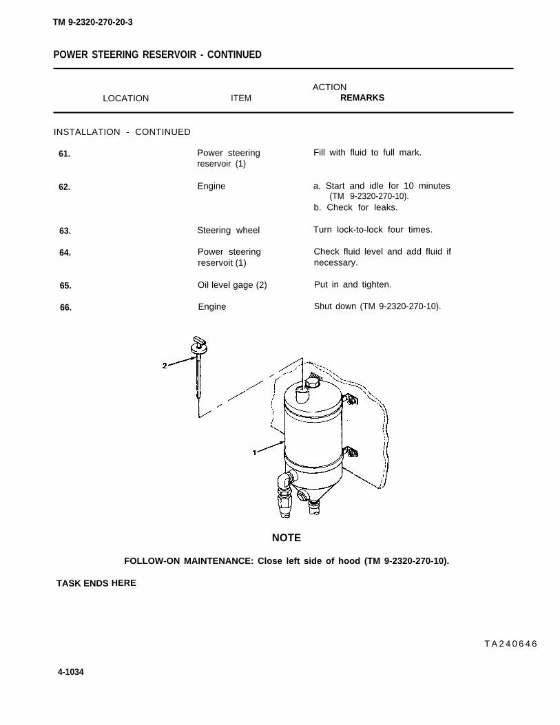
TM 9-2320-270-20-3
POWER STEERING RESERVOIR - CONTINUED
ACTIONLOCATION ITEM REMARKS
INSTALLATION - CONTINUED
61. Power steeringreservoir (1)
62. Engine
63.
64.
65.
66.
TASK ENDS
Steering wheel
Power steeringreservoit (1)
Oil level gage (2)
Engine
Fill with fluid to full mark.
a. Start and idle for 10 minutes(TM 9-2320-270-10).
b. Check for leaks.
Turn lock-to-lock four times.
Check fluid level and add fluid ifnecessary.
Put in and tighten.
Shut down (TM 9-2320-270-10).
NOTE
FOLLOW-ON MAINTENANCE: Close left side of hood (TM 9-2320-270-10).
HERE
T A 2 4 0 6 4 6
4-1034

TM 9-2320-270-20-3
STEERING ALINEMENT
This task covers:
Alinement (page 4-1035)
INITIAL SETUP
Tools Tools – Continued
Chisel, cold-hand, 1/2-inch cut Wrench, open-end, 3/4-inch (two required)Gage, front wheel alinement Wrench, open-end, 15/16-inch (two required)Gage, thicknessHammer, machinist’s ball-peen Personnel RequiredHandle, ratchet, 1/2-inch driveSocket, 15/16-inch, 1/2-inch drive TwoWrench, box, 15/16-inch
ACTIONLOCATION ITEM REMARKS
ALINEMENT
1.
2.
3.
Truck
All tires
Front wheels (1)
Park on level surface with wheels positionedstraight ahead.
Check pressure (TM 9-2320-270-10).
Using alinement gage, check front wheeltoe-in.
Toe-in should be 1/8=inch (3.17millimeter). If toe-in is correct,continue at step 8.
TA240647
4-1035

TM 9-2320-270-20-3
STEERING ALINEMENT - CONTINUED
ACTIONLOCATION ITEM REMARKS
ALINEMENT
4.
5.
Left (1) and right Four clamp screws(2) tie rod ends to (4) and nuts (5)tie rod (3)
6. Front wheels (6)
7.
8.
9.
10.
11.
12.
Tie rod ends (1)and (2)
Tie rod (3)
Tie rod ends (1) Four clamp screwsand (2) (4) and nuts (5)
Pitman arm stop Two inner nuts (9)bracket (7), twostopscrews (8)
Pitman arm stop Two stopscrews (8)bracket (7)
Left front axle ball Locknut (12)socket (10) frontstopscrew (11)
WARNING
Using 15/16-inch box wrench, 15/16-inchsocket, and handle, unscrew part way.
Using ball-peen hammer and cold chisel,spread clamp ends enough to be able toturn tie rod (3).
Do not drive chisel into threads.
Using wheel alinement gage and pipewrench, adjust toe-in to 0-1/8 inch(3.17 millimeter) by turning tie rod (3).
Looking toward the right tie rodend, turning tie rod clockwiseincreases toe-in, counterclockwisedecreases toe-in.
Using 15/16-inch box wrench, socket, andhandle, tighten.
Using two 3/4-inch open-end wrenches,unscrew down to heads of stopscrews (8).
Using 3/4-inch open-end wrench, screw upagainst bracket (7).
Using two 15/16-inch open-end wrenches,unscrew up to head of stopscrew (11).
Do not use open-end wrench to break stopscrews loose. Open-end wrench will slipcausing injury to personnel.
Left front axle Stopscrew(11) Using 15/16-inch box wrench, break looseball socket (10) and screw against ball socket (10).
Right front axle Locknut (15) Using two 15/16-inch open-end wrenches,ball socket (13) unscrew up to head of stopscrew (14).front stopscrew(14)
4-1036

TM 9-2320-270-20-3
STEERING ALINEMENT - CONTINUED
ACTIONLOCATION ITEM REMARKS
13. Right front axle Stopscrew (14) Using 15/16-inch box wrench, break looseball socket (13) and screw against ball socket (13).
TA240648
4-1037

STEERING ALINEMENT - CONTINUED
ACTIONLOCATION ITEM REMARKS
ALINEMENT - CONTINUED
14. Engine Have assistant start(TM 9-2320-270-10).
Do not get between wheels and fender, or between other moving and stationary parts,while assistant is turning wheels. There is no clearance for personnel in these areaswhen turning vehicle.
Hearing protection must be worn while working under truck with engine running to pre-vent possible ear injury.
15. Steering wheel Have assistant turn left all the way.
16. Left ball socket (1) Rear stopscrew (2) Make sure stopscrew (2) is against axlebail (3).
17. Right ball Front stopscrew (5) Using 15/16-inch open-end wrench, screwsocket (4) tight against axle ball (6).
18. Front stopscrew (5) Locknut (7) Using two 15/16-inch open-end wrenches,screw tight against ball socket (4) to lockup stopscrew (5).
WARNING
Do not get between wheels and fender, or between other moving and stationary parts,while assistant is turning wheels. There is no clearance for personnel in these areaswhen turning vehicle.
Hearing protection must be worn while working under truck with engine running to pre-vent possible ear injury.
19. Steering wheel Have assistant turn right all the way.
20. Right ball Rear stopscrew (8) Make sure stopscrew (8) is against axlesocket (4) ball (6).
21. Left ball Front stopscrew (9) Using 15/16-inch open-end wrench, screwsocket (1) tight against axle ball (3).
4-1038
TM 9-2320-270-20-3
W A R N I N G

STEERING ALINEMENT - CONTINUED
ACTIONLOCATION ITEM REMARKS
22. Stopscrew (9) Locknut (10) Using two 15/16-inch open-end wrenches,screw tight against ball socket (1) to lockstopscrew (9).
23. Right end of front Right front stop- s. Place 1/16-inch thickness gageaxle (11) screw (5) and right between.
axle ball (6) b. Have assistant slowly turn steeringwheel to the left until stopscrew (5)is stopped by thickness gage.
c. Have assistant hold steering wheel inthis position.
24. Pitman arm stop Front stopscrew (13)bracket (12)
25. Front stopscrew (13) Locknut (15)
Using two 3/4-inch wrenches, screw stopscrew (13) firmly against pitman arm (14).
Using two 3/4-inch wrenches, tighten.
TA240649
4-1039
TM 9-2320-270-20-3

STEERING ALINEMENT - CONTINUED
ACTIONLOCATION ITEM REMARKS
ALINEMENT - CONTINUED
W A R N I N G
Do not get between wheels and fender, or between other moving and stationary parts,while assistant is turning wheels. There is no clearance for personnel in these areaswhen turning vehicle.
Hearing protection must be worn while working under truck with engine running to pre-vent possible ear injury.
26. Left end of front Left front stopscrew a. Place 1/16-inch thickness gage be-axle (1) (2) and left axle tween axle ball (3) and stopscrew (2).
ball (3) b. Have assistant slowly turn steeringwheel to the right until stopscrew (2)is stopped by thickness gage.
c. Have assistant hold steering in thisposition.
27. Pitman arm stopbracket (4)
28. Rear stopscrew (5)
29.
30.
Rear stopscrew (5) Using two 3/4-inch wrenches, hold outernut (6) and screw stopscrew (5) firmlyagainst pitman arm (7).
Locknut (8) Using two 3/4-inch wrenches, tightenlocknut (8).
Steering wheel Have assistant turn straight ahead.
Engine Shut down (TM 9-2320-270-10).
4-1040
TM 9-2320-270-20-3
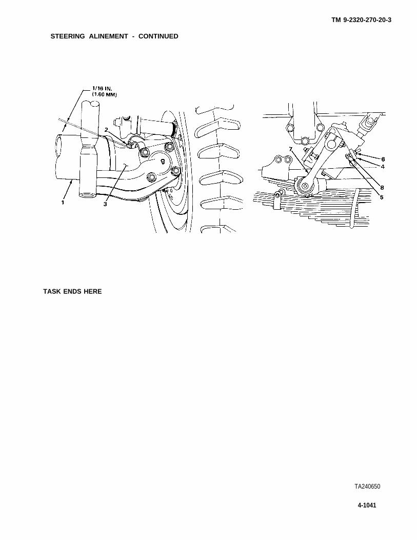
TM 9-2320-270-20-3
STEERING ALINEMENT - CONTINUED
TASK ENDS HERE
TA240650
4-1041

TM 9-2320-270-20-3
Section XIV. FRAME AND TOWING ATTACHMENT MAINTENANCE
Page Page
Fifth Wheel Oscillator Lockouts . . . . . . . . . . . . . . . . . 4-1064 Spare Tire Winch Cable . . . . . . . . . . . . . . . . . . . . . . . . . . . . . 4-1062Front Bumper Brackets and Towing Spare Tire Mount, Winch, and
Eyes . . . . . . . . . . . . . . . . . . . . . . . . . . . . . . . . . . . . . . . . . . . . . . . . . . . . . . . . . . . 4-1051 Cable . . . . . . . . . . . . . . . . . . . . . . . . . . . . . . . . . . . . . . . . . . . . . . ....... . 4-1055Front Bumper . . . . . . . . . . . . . . . . . . . . . . . . . . . . . . . . . . . . . . . . . . . . . . . . 4-1042 Towing Pintle . . . . . . . . . . . . . . . . . . . . . . . . . . . . . . . . . . . . . . . . . . . . . . 4-1045Rear Towing Eyes . . . . . . . . . . . . . . . . . . . . . . . . . . . . . . . . . . . . . . . . . 4-1054
This task covers:
a. Removal (page 4-1042)b. Installation (page 4-1044)
INITIAL SETUP
Tools
Handle, ratchet, 1/2-inch driveSocket, 3/4-inch, 1/2-inch driveSocket, 15/16-inch, 1/2-inch driveSocket, 1 1/18-inch, 1/2-inch driveWrench, box, 3/4-inchWrench, box, 15/16-inchWrench, open-end, 1 1/8-inch
Materials/Parts
Self-locking nut, blackout light guard tobumper
Self-locking nut, bumper (four required)Self-locking nut, grille guard to bumper
(two required)
Personnel Required
Two
ACTIONLOCATION ITEM REMARKS
REMOVAL
1. Blackout light guard Self-locking nut(1) to bumper (2) (3), two washers
(4), and bolt (5)
2. Grille guard (6)to bumper(2)
Two self-lockingnuts (7), fourwashers (8), andtwo bolts (9)
a. Using 3/4-inch socket, ratchet, and3/4-inch box wrench, unscrew and takeout.
b. Get rid of self-locking nut (3).
a. Using 15/16-inch socket, ratchet, and15/16-inch box wrench, unscrew andtake out.
b. Get rid of two self-locking nuts (7).
4-1042

TM 9-2320-270-20-3
FRONT BUMPER - CONTINUED
ACTIONLOCATION ITEM REMARKS
3.
4.
Bumper (2) to two Four self-locking a. Using 1 1/8-inch socket, ratchet, andbrackets (10) nuts (11), eight 1 1/8-inch open-end wrench, unscrew
washers (12), and and take out.four bolts (13) b. Get rid of self-locking nuts (11).
WARNING
Some parts are heavy. Be careful when handling them. Lifting equipment is neededwhen parts weigh over 50 pounds (23 kg) for a single person lift, over 100 pounds(45 kg) for a two person lift, and over 150 pounds (68 kg) for a three or more personlift. Do not try to handle heavy parts without lifting equipment. Keep clear of heavy partssupported only by lifting equipment. Failure to observe this precaution could causeserious injury or death of personnel.
Two towing eyes (14) Bumper (2) Pull forward and take off.
TA240651
4-1043

TM 9-2320-270-20-3
FRONT BUMPER - CONTINUED
ACTIONLOCATION ITEM REMARKS
INSTALLATION
WARNING
Some parts are heavy. Be careful when handling them. Lifting equipment is neededwhen parts weigh over 50 pounds (23 kg) for a single person lift, over 100 pounds(45 kg) for a two person lift, and over 150 pounds (68 kg) for a three or more personlift. Do not try to handle heavy parts without lifting equipment. Keep clear of heavy partssupported only by lifting equipment. Failure to observe this precaution could causeserious injury or death of personnel.
5. Towing eyes (1)
6. Bumper (2) tobracket (3)
7. Grille guard (7)to bumper(2)
8. Blackout lightguard (11) tobumper (2)
TASK ENDS HERE
4-1044
Bumper (2)
Four bolts (4),eight washers (5),and four new self-Iocking nuts (6)
Two bolts (8), fourwashers (9), andtwo new self-lockingnuts (10)
Bolt (1 2), twowashers (13), andnew self-lockingnut (14)
Put on and push against brackets (3).
Screw in and tighten using 1 1/8-inchsocket, ratchet, and 1 1/8-inch open-endwrench.
Screw in and tighten using 15/16-inchsocket, ratchet, and 15/16-inch boxwrench.
Screw in and tighten using 3/4-inchsocket, ratchet, and 3/4-inch boxwrench.
TA240652

TM 9-2320-270-20-3
TOWING PINTLE
This task covers:
a. Removal (page 4-1046) c. Assembly (page 4-1048)b. Disassembly (page 4-1047) d. Installation (page 4-1050)
INITIAL SETUP
Tools
Bar, pryChisel, cold hand, 1/2-inchDrill, electric, portableDrill twist, 3/16-inchExtension, 10-inch, 1/2-inch driveExtension, 10-inch, l-inch driveFile, flatGun, greaseHammer, machinist’s ball-peenHandle, ratchet, 1/4-inch driveHandle, ratchet, 1/2-inch driveHandle, ratchet, 1-inch drivePliers, slip-joint, straight-nosePunch, drive-pin, 1/8-inchPunch, drive-pin, tapered, 5/16-inchSocket, 5/16-inch, 1/4-inch driveSocket, 1 1/8-inch, 1/2-inch drive
Tools – Continued
Socket, 1 1/2-inch, l-inch driveSocket, 2 1/4-inch, l-inch driveViseWrench, open-end, 1 1/8-inchWrench, open-end, 1 1/2-inch
Materials/Parts
Cotter pin, lock slotted nutCotter pin, S-linkCotter pin, slotted nutGrease (LO 9-2320-270-12)Screw, drive
Personnel Required
Two
4-1045

TM 9-2320-270-20-3
TOWING PINTLE - CONTINUED
3.
Cotter pin (3)
Slotted nut (2) andtwo washers (4)
ACTION
LOCATION ITEM REMARKS
REMOVAL
1. Pintle (1) and a. Using pliers, straighten and take out.
slotted nut (2) b. Get rid of.
2. Pintle (1) With help from assistant and using prybar, 2 1/4-inch socket, 10-inch extension,and l-inch drive handle, unscrew and takeoff.
Take out.
CAUTION
Do not wedge wrench against lights to hold bolts. Have assistant hold wrench. Putting
Pintle (1)
pressure on-taillight or blackout light can break it.
4. Inner bracket (5)and outerbracket (6)
5. Frame (9)
Two nuts (7) andbolts (8)
Inner bracket (5)
Using 1 1/8-inch socket, 10-inch exten-sion, 1/2-inch drive handle, and 1 1/8-inch wrench, unscrew and take off.
Take off.and outerbracket (6)
TA240653
4-1046

TM 9-2320-270-20-3
TOWING PINTLE - CONTINUED
ACTIONLOCATION ITEM REMARKS
DISASSEMBLY
6. Chain (10) S-link(11) and a. Pull out pin (12).cotter pin (12) b. Using pliers, open S-link(11)
and take off.c. Get rid of pin (12).
7. S-link(11) Using pliers, open and take off.
NOTE
Do not remove drive screw and chain unless last link of chain is broken. if any other linkis broken, use an S-link to repair chain,
8. Chain (10) to Drive screw (13) a.pintle (1) b.
c.
d.
Using hammer and chisel, cut off top.Using hammer and 1/6-inch drive-pinpunch, make centering mark.Using 3/16-inch drill twist and electricdrill, drill out screw (13).Using fiat file, smooth area flush
9. Pintle (1)
with side of pintle (1).
Two grease Using 5/16-inch socket and 1/4-inch drivefittings (14) ratchet, unscrew and take out.
TA240654
4-1047

TM 9-2320-270-20-3
TOWING PINTLE - CONTINUED
ACTIONLOCATION ITEM REMARKS
DISASSEMBLY - CONTINUED
10. Slotted nut (1) Cotter pin (2) a.b.
11. Pintle lock (3) to Slotted nut (1) a.pintle hook (4) and screw (5) b.
Pintle lock (3) a.b.
12. Pintle hook (4)
CAUTION
Using pliers, straighten and take out.Get rid of.
Secure assembly in vise.Using 1 1/2-inch socket, l-inch drivehandle, and 1 1/2-inch open-endwrench, unscrew and take out.
Take out.Take assembly out of vise.
To prevent damage to threads, drive out latch pin from plain side.
13. Pintle latch (6) Latch pin (7) Support pintle lock (3) in vise and usingto pintle lock (3) hammer and 5/16-inch drive-pin punch,
drive out.
14. Pintle lock (3) Pintle latch (6) a. Take out.and spring (8) b. Take lock (3) out of vise.
15. Outer pintle Grease fitting (10) Using 5/16-inch socket and 1/4-inch drivebracket (9) handle, unscrew and take out.
ASSEMBLY
16. Outer pintlebracket (9)
17. Pintle lock (3)
Grease fitting (10) Screw in and tighten using 5/16-inchsocket and handle with 1/4-inch drive.
Spring (8) and Put together.pintle latch (6)
CAUTION
To prevent damage to threads, drive in latch pin from plain side.
18. Pintle latch (6) Latch pin (7) a. Support pintle lock (3) in vise.to pintle lock (3) b. Using hammer and 5/16-inch drive-pin
punch, drive in.c. Take lock (3) out of vise.
19. Pintle hook (4) Pintle lock (3) a. Put pintle hook (4) in vise.b. Put together.
4-1048

TM 9-2320-270-20-3
TOWING PINTLE - CONTINUED
ACTIONLOCATION ITEM REMARKS
20. Pintle hook (4) to Screw (5) and a. Screw together and tighten using 1 1/2-pintle lock (3)
21. Slotted nut (1)
22. Pintle lock (3)and latch pin (7)
23. Pintle hook (4)
24. Chain (12)
25. S-link (14)
slotted nut (1) inch socket, l-inch drive handle, and1 1/2-inch open-end wrench.
b. Take pintle hook (4) out of vise.
New cotter pin (2) a. Put in.b. Use pliers to bend ends of cotter
pin (2).
Two grease Screw in and using 5/16-inch socket andfi t t ings(n) 1/4-inch drive handle, tighten.
NOTE
If chain and drive-pin were not removed, go to step 24.
Chain (12) and drive a. Put on.screw (13) b. Using hammer, drive in.
S-link (14) Put on and using pliers, close.
New cotter pin (15) a. Put on and using pliers, close.b. Put cotter pin (15) in hook (4).
TA240655
4-1049

TM 9-2320-270-20-3
TOWING PINTLE - CONTINUED
ACTIONLOCATION ITEM REMARKS
INSTALLATION
CAUTION
Do not wedge wrench against lights to hold bolts. Have assistant hold wrench. Puttingpressure on taillight or blackout Iight can break It.
26. Frame (1) Inner bracket (2) Place in position.and outer bracket (3)
27. Inner bracket (2) Two nuts (4) and Screw in and tighten using 1 1/8-inchand outer two screws (5) socket, 10-inch extension, 1/2-inchbracket (3) drive handle, and 1 1/8 -Inch wrench.
28. Outer bracket (3) Pintle (6) Put in.
Have assistant use pry bar to keep pintle from turning while tightening slotted nut. Pintlelock must be closed and latched.
29. Pintle (6) Two washers (7) Put on.
30. Slotted nut (8) a. Put on.b. Using 2 1/4-inch socket, 10-inch
extension, l-inch drive handle, and prybar, tighten.
c. Back off just enough so pintIe turnsfreely.
31. Slotted nut (8)
32. Pintle (6) andouter bracket (3)
Cotter pin (9)
Three greasefittings (10)
Using pliers, put in.
Using grease gun, lubricate(LO 9-2320-270-12).
4-1050
NOTE

TM 9-2320-270-20-3
TOWING PINTLE - CONTINUED
TASK ENDS HERE
FRONT BUMPER BRACKETS AND TOWING EYES
This task covers:
a. Removal (page 4-1052)b. Installation (page 4-1052)
lNITIAL SETUP
Tools Materials/Parts - Continued
Handle, ratchet, 1/2-inch drive Self-locking nutsSocket, 1 1/8-inch, 1/2-inch drive (two required)Wrench, box, 1 1/8-inchWrench, open-end, 1 1/8-inch Personnel Required
Materials/Parts One
towing eye to frame,
Self-locking nuts, bumper bracket Equipment Conditionand towing eyes to frame (fourrequired) Front bumper removed (page 4-1042).
TA240656
4-1051

TM 9-2320-270-20-3
FRONT BUMPER BRACKETS AND TOWING EYES - CONTINUED
ACTIONLOCATION ITEM REMARKS
This task is the same for either
REMOVAL
1. Bumper bracket (1) Four self-lockingand towing eye nuts (4), washers(2) to frame (3) (5), four bolts (6),
washers (7), and
NOTE
2. Towing eye (2) toframe (3)
INSTALLATION
3. Frame (3)
4. Towing eye (2) toframe (3)
5.
6. Bumper bracket (1)to frame (3)
right or left
bumper brackets (1)
Two self-lockingnuts (8), washer(9), two bolts (10),washers (11), andtowing eye (2)
Towing eye (2), twobolts (10), andwashers (11)
Two washers (9) andnew self-lockingnuts (8)
Bumper bracket (l),four bolts (6), andwashers (7)
Four new self-Iocking nuts (4)and washers (5)
a.
b.
a.
b.
side. Left side is shown.
Using 1 1/8-inch socket, ratchet, and1 1/8-inch open-end wrench, unscrewand take off.Get rid of self-locking nuts (4).
Using 1 1/8-inch socket, ratchet, and1 1/8-inch box wrench, unscrew andtake off.Get rid of self-locking nuts (8).
Place in position.
Using 1 1/8-inch socket, ratchet, and1 1/8-inch box wrench, screw togetherand tighten.
Place in position.
Using 1 1/8-inch socket, ratchet, and1 1/8-inch open-end wrench, screw on andtighten.
4-1052

TM 9-2320-270-20-3
FRONT BUMPER BRACKETS AND TOWING EYES - CONTINUED
FOLLOW-ON
TASK ENDS HERE
REAR TOWING EYES
NOTE
MAINTENANCE: Install front bumper (page 4-1042).
This task covers:
a. Removal (page 4-1054)b. Installation (page 4-1054)
INITIAL SETUP
Tools
Handle, ratchet, 1/2-inch driveSocket, 15/16-inch, 1/2-inch driveWrench, open-end, 15/16-inch
Materials/Parts – Continued
Self-locking nuts, towing eye to frame(eight required)
Personnel RequiredMaterials/Parts
OneSelf-locking nuts, splash shield to
towing eye (three required)
ACTIONLOCATION ITEM REMARKS
NOTE
This task shows right side rear towing eyes. Procedure is the same for left side,TA240657
4-1053

TM 9-2320-270-20-3
REAR TOWING EYES - CONTINUED
ACTION
LOCATION ITEM REMARKS
REMOVAL
1. Splash shield Three self-locking
assembly (1) to nuts (3), six washers
towing eye (2) (4), three bolts (5),and splash shieldassembly (1)
2. Towing eye (2) to Eight self-lockingframe (6) nuts (7), 16 washers
(8), eight bolts (9),and towing eye (2)
INSTALLATION
3. Frame (6) Towing eye (2),eight bolts (9), 16washers (8), andeight new self-Iocking nuts (7)
4. Towing eye (2) Splash shieldassembly (1), threebolts (5), sixwashers (4), andthree new self-Iocking nuts (3)
a.
b.
a.
b.
a.b.
a.b.
Using 15/16-inch socket, ratchet, and15/16-inch wrench, unscrew nuts andtake off.Get rid of self-locking nuts (3).
Using 1 1/8-inch socket, ratchet, and15/16-inch wrench, unscrew and takeoff.Get rid of self-locking nuts (7).
Place in position.Using 15/16-inch socket, ratchet, and15/16-inch wrench, tighten.
Place in position.Using 15/16-inch socket, ratchet, and15/16-inch wrench, tighten.
TASK ENDS HERE T A 2 4 0 6 5 6
4-1054

TM 9-2320-270-20-3
SPARE TIRE MOUNT, WINCH, AND CABLE
This task covers:
a. Removal (page 4-1056) c. Assembly (page 4-1058)b. Disassembly (page 4-1057) d. Installation (page 4-1060)
INITIAL SETUP
Tools Materials/Parts - Continued
Handle, ratchet, 1/2-inch drivePliers, slip-joint, angle-noseSocket, 7/16-inch, 1/2-inch driveSocket, 9/16-inch, 1/2-inch driveSocket, 15/16-inch, 1/2-inch driveWrench, box, 9/16-inchWrench, box, 15/16-inch
Lockwashers, winch to spare tire mount(three required)
Self-locking nut, spare wheel carrier pulleywheel
Personnel Required
ThreeMaterials/Parts
Equipment ConditionSelf-locking nuts, spare tire
mount to frame (four required)Self-locking nuts, bracket to
platform (two required)
Spare tire removed (TM 9-2320-270-10).
4-1055

TM 9-2320-270-20-3
SPARE TIRE MOUNT, WINCH, AND CABLE - CONTINUED
ACTIONLOCATION ITEM REMARKS
REMOVAL
WARNING
When removing or installing mounting hardware, assistants must hold spare tire mountto prevent it falling and causing injury to personnel.
1. Spare tire mount Four self-locking a.(1) to frame (2) nuts (3), eight
washers (4), andfour bolts (5) b.
2. Bracket (6) to Two self-locking a.platform (7) nuts (8), two
washers (9), bracket(6), bracket plate b.(10), bolts (11),and washers (12)
Using 15/16-inch socket, ratchet, and15/16-inch box wrench, unscrew andtake off.Get rid of self-locking nuts (3).
Using 15/16-inch socket, ratchet, and15/16-inch box wrench, unscrew andtake off.Get rid of self-locking nuts (8).
3. Frame (2) Spare tire mount (1) With help from assistants, take off.
TA240659
4-1056

TM 9-2320-270-20-3
SPARE TIRE MOUNT, WINCH, AND CABLE - CONTINUED
ACTIONLOCATION ITEM REMARKS
DISASSEMBLY
4. Spare tire mount(1) and bolt (13)
5.
6. Wheel (16)
7. Winch (19)
8.
9.
10.
Self-locking a. Using 9/16-inch socket, ratchet, andnut (14) 9/16-inch box wrench, unscrew and
take off.b. Get rid of self-locking nut (14).
Bolt (13), two Take out.washers (15), wheel(16), and washer (17)
Bearing (18) Push out.
Winch lever (20) Put in drum released position.
WARNING
Leather gloves must be worn when handling cable to prevent cuts and scrapes. Never letcable run through hands. Broken and frayed wires can cause injury.
Cable (21) and Have assistant pull on cable as you, usingcrank (22) crank (22), unwind it.
Nut (23) and Using 7/16-inch socket and ratchet handle,clamp (24) unscrew and take off.
Cable (21) Take off.
TA240660
4-1057

SPARE TIRE MOUNT, WINCH, AND CABLE - CONTINUED
ACTIONLOCATION I T E M REMARKS
DISASSEMBLY - CONTINUED
11.
12.
Winch (1) to spare Three nuts (3),tire mount (2) Iockwashers (4),
and bolts (5)
Spare tire mount (2) Winch (1)
ASSEMBLY
13. Spare tire mount (2) Winch (1)
14. Winch (1) to spare Three nuts (3), newtire mount (2) Iockwashers (4), and
bolts (5)
a. Using 9/16-inch socket, ratchet, and9/16-inch box wrench, unscrew andtake off.
b. Get rid of Iockwashers (4).
Lift off.
Place in position.
Screw together and using 9/16-inch socket,ratchet, and 9/16-inch wrench, tighten.
Leather gloves must be worn when handling cable to prevent cuts and scrapes. Never letcable run through hands. Broken and frayed wires can cause injury.
15. Winch (1) Cable (6) Put end through hole.
4-1058
TA240661
TM 9-2320-270-20-3
WARNING

TM 9-2320-270-20-3
SPARE TIRE MOUNT, WINCH, AND CABLE - CONTINUED
ACTIONLOCATION ITEM REMARKS
16. Cable (6) Clamp (7)
17. Clamp (7) Nut (8)
18. Wheel (9) Bearing (10), twowashers (11), andwasher (12)
19. Spare tire mount (2) Wheel (9), twowashers (11), bearing(10), and washer (12)
20. Bolt (13)
21. Bolt (13) New self-lockingnut (14)
Using pliers, bend cable (6) as shown andplace clamp (7) in position.
Screw in and tighten using 7/16-inchsocket and ratchet to tighten.
Apply grease and put together.
Place in position.Make sure cable is on top ofwheel.
Push into place.
Screw on and tighten using 9/16-inchsocket, ratchet, and 9/16-inch boxwrench.
TA240662
4-1059

SPARE TIRE MOUNT, WINCH, AND CABLE-CONTINUED
ACTIONLOCATION ITEM REMARKS
ASSEMBLY - CONTINUED
22. Winch (1) Winch lever (2) Put in wind position.
23. Spare tire mount (3) Hook (4) Secure.
WARNING
Leather gloves must be worn when handling cable to prevent cuts and scrapes. Never letcable run through hands. Broken and frayed wires can cause injury.
24.
INSTALLATION
Crank (5) and With assistant pulling on cable (6) tocable (6) keep tension on it, wind until tight.
When removing or installing mounting hardware, assistants must hold spare tire mountto prevent it falling and causing injury.
25. Frame (7) Spare tire mount (3) Have assistants place in position.
T A 2 4 0 6 6 3
4-1060
TM 9-2320-270-20-3
W A R N I N G

TM 9-2320-270-20-3
SPARE TIRE MOUNT, WINCH, AND CABLE - CONTINUED
ACTIONLOCATION ITEM REMARKS
26. Spare tire mount (3) Four bolts (8),to frame (7) eight washers (9),
and four new self-Iocking nuts (10)
27. Spare tire mount (3) Bracket (12),and platform (11) bracket plate (13),
two washers (14),and two bolts (15)
28. Bolts (15) Two washers (16) andnew self-lockingnuts (17)
Screw in and tighten using 15/16-inchsocket, ratchet, and 15/16-inch boxwrench.
Put in position.
Screw in and tighten using 15/16-inch socket, ratchet, and 15/16-inch boxwrench.
NOTE
FOLLOW-ON MAINTENANCE: Mount spare tire (TM 9-2320-200-10).
TASK ENDS HERE
TA240664
4-1061

TM 9-2320-270-20-3
SPARE TIRE WINCH CABLE
This task covers:
a. Removal (page 4-1062)b. Installation (page 4-1062)
INITIAL SETUP
Tools Personnel Required
Pliers, slip-joint TwoHandle, ratchet, 3/8-inch driveSocket, 7/16-inch, 3/8-inch drive
ACTIONLOCATION ITEM REMARKS
REMOVAL
1. Spare tire mount Winch Iever (3) Put in drain released position.(1) and winch (2)
Leather gloves must be worn when handling cable to prevent cuts and scrapes. Never letcable run through hands.
2.
3.
4. Winch (2)
5. Cable wheel (8)and spare tiremount (1)
INSTALLATION
Broken and frayed wires can cause injury.
Cable (4) and Have assistant pull on cable as you, usingcrank (5) crank, unwind it until there is less than
Nut (7) andclamp (6)
Cable (4)
Cable (4)
6. Spare tire mount Cable (4)(1) and wheel (8)
7. Winch (2) Cable (4)
one turn of cable left and clamp (6) isaccessible.
Using 7/16-inch socket and ratchet handle,unscrew and take off.
Route end through hole and pull off.
a. Pull through.b. Look for broken and frayed wires.
Route between.
Route through hole.
4-1062
WARNING

TM 9-2320-270-20-3
SPARE TIRE WINCH CABLE- CONTINUED
ACTIONLOCATION ITEM REMARKS
8. Cable (4) and Using pliers, bend cable (4) as shown andclamp (6) hold in place with clamp (6).
9. Clamp (6) Nut (7) Screw on and tighten using ratchet and7/16-inch socket.
10. Winch (2) Winch lever (3) Put in wind position.
WARNING
Leather gloves must be worn when handling cable to prevent cuts and scrapes. Never letcable run through hands. Broken and frayed wires can cause injury.
11. Crank (5) and Using crank (5), wind on cable (4)cable (4) until there is about 3 feet (1 m) left.
12. Spare tire mount (1) Hook (9) Secure on spare tire mount (1).
13. Crank (5) and Using crank (5), wind in until tight.cable (4)
NOTE
FOLLOW-ON MAINTENANCE: Check winch operation (TM 9-2320-270-10).
TASK ENDS HERE
TA240665
4-1063

TM 9-2320-270-20-3
FIFTH WHEEL OSCILLATOR LOCKOUTS
This task covers:
a. Lock (page 4-1064)b. Unlock (page 4-1064)
INITIAL SETUP
Tools Personnel Required
Hammer, plastic OneWrench, 3/4-inch
ACTIONLOCATION ITEM REMARKS
NOTE
Fifth wheel oscillator lockouts are adjusted to locked positions (toward center of truck)for normal driving and adjusted to unlocked position for extremely rough ground.
Both oscillator lockouts are adjusted the same. Right side is shown.
LOCK
1. Fifth wheel (1) TWO bolts (2) Using 3/4-inch wrench, unscrew part way.
2. Lockout block (3) a. Push toward center of truck.b. Using hammer, tap lockout toward
center of truck until snug.
3. TWO bolts (2) a. Using 3/4-inch wrench, tighten.b. Repeat steps 1 thru 3 for left side.
UNLOCK
4. Fifth wheel (1)
5.
6.
Two bolts (2) Using 3/4-inch wrench, unscrew part way.
Lockout block (3) Using hammer, tap toward outside of truckto loosen and pull toward outside of truck.
Two bolts (2) a. Using 3/4-inch wrench, tighten.b. Perform steps 4 thru 6 on left side.
4-1064

FlFTH WHEEL OSCILLATOR LOCKOUTS- CONTINUED
TASK ENDS HERE
Section XV. SPRINGS, SHOCK ABSORBERS, AND TORQUE RODS
Page Page
Front Spring Pins . . . . . . . . . . . . . . . . . . . . . . . . . . . . . . . . . . . . . . . . . . 4-1074 Rear Axle Spring LubricationLeft Air Pilot Valve . . . . . . . . . . . . . . . . . . . . . . . . . . . . . . . . . . . . . . . . 4-1065 Fitting . . . . . . . . . . . . . . . . . . . . . . . . . . . . . . . . . . . . . . . . . . . . . . . . . . . . . . 4-1087Pusher Axle Air Load Control Right Air Pilot Valve
Valve. . . . . . . . . . . . . . . . . . . . . . . . . . . . . . . . . . . 4-1070
. . . . . . . . . . . . . . . . . . . . . . . . . . . . . . . . . . . . . . . . . . . . . . . . . . . . . . . . ,. 4-1079 Tandem Axle Torque RodPusher Axle Shock Absorber . . . . . . . . . . . . . . . . . . . . . . . 4-1084 Lubrication Fittings . . . . . . . . . . . . . . . . . . . . . . . . . . . . . . . 4-1085
LEFT AIR PILOT VALVE
This task covers:
a. Removal (page 4-1065) c. Inspection/Replacement (page 4-1068)b. Cleaning (page 4-1068) d. Installation (page 4-1068)
INITIAL SETUP
Tools Materials/Parts
Hammer, plastic Lockwashers (two required)Handle, ratchet, 3/8-inch drive Tag, marking (item 18, appendix C)Pliers, diagonal cutting Tape, teflon (item 22, appendix C)Pliers, long-nose, round Wrap, tie (item 24Pliers, slip-joint, straight-noseSocket, 3/8-inch drive, 7/16-inch Personnel RequiredVise, machinist’s
. Wrench, open-end, 7/16-inch OneWrench, open-end, 5/8-inch
appendix C) ‘
Equipment Condition
Air system drained (TM 9-2320-270-10).TA240666
4-1085
TM 9-2320-270-20-3

TM 9-2320-270-20-3
LEFT AIR PILOT VALVE - CONTINUED
ACTIONLOCATION ITEM REMARKS
REMOVAL
WARNING
Make sure all pressure is drained from air system before disconnecting air lines. Partsunder pressure can, when removed, fly off with great force causing injury to personnel.
NOTE
Tag lines according to general maintenance instructions (page 4-1).
1. Hose harness (1) Two tie wraps (2) a. Using diagonal cutting pliers, cut andtake off.
b. Get rid of.
2. Elbow (3)
3.
4. Elbow (6)
5.
6. Tee (9)
7.
8.
9.
10. Bracket (14)
11.
Hose (4) Using 5/8-inch wrench, unscrew andtake off.
Insert (5) Using long-nose pliers, pull out.
Hose (7) Using 5/8-inch wrench, unscrew andtake off.
Insert (8) Using long-nose pliers, pull out.
Hose (10) Using 5/8-inch wrench, unscrew andtake off.
Insert(n) Using long-nose pliers, pull out.
Hose (12) Using 5/8-inch wrench, unscrew andtake off.
insert (13) Using long-nose pliers, pull out.
Two screws (15), a. Using 7/16-inch wrench, 7/16-inchlockwashers (16), socket and handle with 3/8-inch drive,and nuts (17) unscrew and take out.
b. Get rid of Iockwashers (16).
Left air pilot Take off.valve (18)
4-1066

TM 9-2320-270-20-3
LEFT AIR PILOT VALVE - CONTINUED
ACTIONLOCATION ITEM REMARKS
12. Left air pilot Elbow (3)valve (18)
13.
14.
15.
Elbow (6)
Tee (9)
Screened ventvalve (19)
a. Secure valve (18) in vise.b. Using 5/8-inch wrench, unscrew and
take off.
Using 5/8-inch wrench, unscrew and takeoff.
Using 5/8-inch wrench, unscrew and takeoff.
a. Using slip-joint pliers, unscrew andtake out.
b. Take valve (18) out of vise.
TA240667
4-1067

TM 9-2320-270-20-3
LEFT AIR PILOT VALVE - CONTINUED
ACTIONLOCATION ITEM REMARKS
CLEANING
16. All parts Clean according to general maintenanceinstructions (page 4-1).
lNSPECTION/REPLACEMENT
17. All parts Inspect according to general maintenanceinstructions (page 4-1).
19.
20.
21.
Elbow (3)
Tee (4)
Screened ventvalve (5)
18. Air pilot valve (1) Elbow (2) a.b.
c.
a.
b.
a.
b.
a.
b.
c.
Secure valve (1) in vise.Wrap threads with teflon tape(page 4-1).Using 5/8-inch wrench, screw in andtighten.
Wrap threads with teflon tape(page 4-1).Using 5/8-inch wrench, screw in andtighten.
Wrap threads with teflon tape(page 4-1).Using 5/8-inch wrench, screw in andtighten.
Wrap threads with teflon tape(page 4-1).Using slip-joint pliers, screw in andtighten.Take valve (1) out of vise.
22. Bracket (6)
23. Air pilot valve (1)
24. Elbow (2)
25.
26. Elbow (3)
Air pilot valve (1) Place in position.
Two screws (7), new Screw in and tighten using 7/16-inchIockwashers (8), socket, handle with 3/8-inch drive andand nuts (9) 7/16-inch wrench.
Insert (10) Using hammer, tap in.
Hose (11) Screw on and tighten.
Insert (12) Using hammer, tap in.
4-1068

TM 9-2320-270-20-3
LEFT AIR PILOT VALVE - CONTINUED
LOCATION ITEMACTION
REMARKS
27.
28. Tee (4)
Hose (13)
Two inserts (14)
Screw on and tighten using 5/8-inchwrench.
Using hammer, tap in.
29. Hose (15) Screw on and tighten using 5/8-inchwrench.
30.
31. Hose harness (17)
Hose (16) Screw on and tighten using 5/8-inchwrench.
TWO new tie a. Put hoses together.wraps (18) b. Using pliers, put on.
TASK ENDS HERE
TA240668
4-1069

TM 9-2320-270-20-3
RIGHT AIR PILOT VALVE
This task covers:
a. Removal (page 4-1070) c. Inspection/Replacement (page 4-1072)b. Cleaning (page 4-1072) b. Installation (page 4-1072)
INITIAL SETUP
Tools
Hammer, plasticHandle, ratchet, 3/8-inch drivePliers, diagonal-cuttingPliers, long-nose, roundPliers, slip-joint, straight-noseSocket, 3/8-inch drive, 7/16-inchVise, machinist’sWrench, open-end, 7/16-inchWrench, open-end, 5/8-inch
Materials/Parts
Lockwashers (two required)Tag, marking (item 18, appendix C)Tape, teflon (item 22, appendix C)Wrap, tie (item 24, appendix C)
Personnel Required
One
Equipment Condition
Air system drained (TM 9-2320-270-10).
ACTIONLOCATION ITEM REMARKS
REMOVAL
Make sure all pressure is drained from air system before disconnecting air lines. Partsunder pressure can, when removed, fly off with great force causing injury to personnel.
NOTE
Tag lines according to general
1. Hose harness (1) Two tie wraps (2)
2. Elbow (3)
3.
Hose (4)
insert (5)
maintenance instructions (page 4-1).
a. Using diagonal-cutting pliers, cut andtake off.
b. Get rid of.
Using 5/8-inch wrench, unscrew andtake off.
Using long-nose pliers, pull out.
4-1070
WARNING

TM 9-2320-270-20-3
RIGHT AIR PILOT VALVE - CONTINUED
ACTIONLOCATION ITEM REMARKS
4. Elbow (6) Hose (7) Using 5/8-inch wrench, unscrew andtake off.
5. insert (8) Using long-nose pliers, pull out.
6. Tee (9) Hose (10) Using 5/8-inch wrench, unscrew andtake off.
7. Hose (11) Using 5/8-inch wrench, take off,
8. Two inserts (12) Using long-nose pliers, pull out.
9. Bracket (13) Two screws (14), a. Using 7/16-inch wrench, socket, andIockwashers (15), ratchet handle, unscrew and take out.and nuts (16) b. Get rid of lockwashers (15).
10. Right air pilot Take off.valve (17)
TA240669
4-1071

TM 9-2320-270-20-3
RIGHT AIR PILOT VALVE - CONTINUED
ACTIONLOCATION ITEM REMARKS
REMOVAL - CONTINUED
11. Right air pilotvalve (1)
12.
13.
14.
CLEANING
15.
lNSPECTION/REPLACEMENT
16.
INSTALLATION
17. Right air pilotvalve (1)
18.
19.
20.
Elbow (2) a. Secure valve (19) in vise.b. Using 5/8-inch wrench, unscrew and
take out.
Elbow (3) Using 5/8-inch wrench, unscrew and takeout.
Tee (4) Using 5/8-inch wrench, unscrew and takeout.
Screened vent a. Using slip-joint pliers, unscrew andvalve (5) take out.
b. Take valve (1) out of vise.
All parts
All parts
Elbow (2)
Elbow (3)
Tee (4)
Screened ventvalve (5)
Clean according to general maintenanceinstructions (page 4-1).
Inspect according to general maintenanceinstructions (page 4-1).
a.
b.
a.
b.
a.
Secure valve (1) in vise.Wrap threads with teflon tape(page 4-1).Using 5/8-inch wrench, screw in andtighten.
Wrap threads with teflon tape(page 4-1).Using 5/8-inch wrench, screw in andtighten.
Wrap threads with teflon tape(page 4-1).Using 5/8-inch wrench, screw in andtighten.
Wrap threads with teflon tape(page 4-1).
4-1072

TM 9-2320-270-20-3
RIGHT AIR PILOT VALVE - CONTINUED
ACTIONLOCATION ITEM REMARKS
23. Elbow (2)
24.
25. Elbow (3)
26.
27. Tee (4)
28.
29.
20. Continued
21. Bracket (6) Air pilot valve (1)
22. Air pilot valve (1) Two screws (7), newIockwashers (8),and nuts (9)
Insert (10)
Hose (11)
Insert (12)
Hose (13)
Two inserts (14)
Hose (15)
Hose (16)
b. Using slip-joint pliers, screw in andtighten.
c. Take valve (1) out of vise.
Place in position.
Screw in and tighten using 7/16-inchwrench.
Using hammer, tap in.
Screw in and tighten using 5/8-inchwrench.
Using hammer, tap in.
Screw on and tighten using 5/8-inchwrench.
Using hammer, tap in.
Screw on and tighten using 5/8-inchwrench.
Screw on and tighten using 5/8-inchwrench.
TA240670
4-1073

TM 9-2320-270-20-3
RIGHT AIR PILOT VALVE - CONTINUED
ACTIONLOCATION ITEM REMARKS
INSTALLATION - CONTINUED
30. Hose harness (1) Two new tie Using slip-joint pliers, put on.wraps (2)
NOTE
FOLLOW-ON MAINTENANCE: Check for proper operation (TM 9-2320-270-10) andcheck for air leaks (page 4-1).
TASK ENDS HERE
FRONT SPRING PINS
This task covers:
a. Front Front Pin Removal d. Front Rear Pin Removal (page 4-1077)
(page 4-1075) e. Front Rear Pin inspection/Replacement
b. Front Front Pin Inspection/ (page 4-1078)Replacement (page 4-1076) f. Front Rear Pin installation (page 4-1078)
c. Front Front Pin Installation (page 4-1076)
INITIAL SETUP
Tools Personnel Required
Driftpin, brass, 1/2-inch One
Hammer, machinist’s ball-peenLifting equipment, 30,000 pound Equipment Condition
capacityPunch, drive pin, 3/16-inch Pitman arm to booster drag link removed
Trestle, automotive (two required) (page 4-962) (for left rear spring pin
Wrench, open-end, 7/16-inch only).
Wrench, open-end, 3/4-inch TA240671
4-1074

TM 9-2320-270-20-3
FRONT SPRING PINS - CONTINUED
ACTIONLOCATION ITEM REMARKS
FRONT FRONT PIN REMOVAL
Some parts are heavy. Be careful when handling them. Lifting equipment is neededwhen parts weigh over 50 pounds (23 kg) for a single person lift, over 100 pounds(45 kg) for a two person lift, and over 150 pounds (66 kg) for a three or more personlift. Do not try to handle heavy parts without lifting equipment. Keep clear of heavy partssupported only by lifting equipment. Failure to observe this precaution could causeserious injury or death of personnel.
1. Truck Frame (1) a. Using lifting equipment, lift.b. Place two trestles in position to
support so that there will be no loadon pins (2).
c. Using lifting equipment, lower onto twotrestles.
2. Shackle pin (2)
3.
4. Bracket (7)
Lubricationfitting (3)
Lockpin (4), washer(5), and nut (6)
Shackle pin (2)
Using 7/16-inch wrench, unscrew and takeout.
a. Using 3/4-inch wrench, unscrew andtake off.
b. Using hammer and punch, drive out.
Using drift and hammer, drive out.
TA240672
4-1075
W A R N I N G

TM 9-2320-270-20-3
FRONT SPRING PINS - CONTINUED
ACTIONLOCATION ITEM REMARKS
FRONT FRONT PIN INSPECTION/REPLACEMENT
N O T E
For more information on how to inspect parts, go to the general maintenance instruc-tions (page 4-1). Replace defective parts as needed.
FRONT FRONT PIN INSTALLATION
5. Bracket (1) Spring (2) Line up holes.
6. Shackle pin (3) Using hammer, drive in.Shackle pin is slotted on end foralinement of shackle pin notch. Slotmust be horizontal and shackle pinnotch down, when installed.
Lockpin (4), washer a. Using hammer, drive in Iockpin (4).(5), and nut (6) Make sure flats line up.
b. Screw on washer (5) and nut (6) andtighten using 3/4-inch wrench.
Lubrication Screw in and tighten using 7/16-inchfitting (7) wrench.
N O T E
If front rear pin will be removed, skip step 9.
7. Shackle pin (3)
8.
9. Truck Frame (8) a.b.c.
Using lifting equipment, lift.Remove trestles.Using lifting equipment, lower.
TA240673
4-1076

TM 9-2320-270-20-3
FRONT SPRING PINS - CONTINUED
ACTIONLOCATION ITEM REMARKS
FRONT REAR PIN REMOVAL
N O T E
If frame has been raised for front front pin removal, skip step 10.
WARNING
Some parts are heavy. Be careful when handling them. Lifting equipment is neededwhen parts weigh over 50 pounds (23 kg) for a single person lift, over 100 pounds(45 kg) for a two person lift, and over 150 pounds (68 kg) for a three or more personlift. Do not try to handle heavy parts without lifting equipment. Keep clear of heavy partssupported only by lifting equipment. Failure to observe this precaution could causeserious injury or death of personnel.
10. Truck Frame (8) a. Using lifting equipment, lift.b. Remove trestles.c. Using lifting equipment, lower.
11. Shackle pin (9)
12.
13. Bracket (14)
Lubrication Unscrew and take out using 7/16-inchfitting (10) wrench.
Lockpin (11), washer a. Using 3/4-inch wrench, unscrew and(12), and nut (13)
Shackle pin (9)
take out.b. Using hammer and punch, drive out
Iockpin (11).
Using hammer and drift, drive out.Shackle pin is threaded on end forlubrication fitting. When drivingout, do not damage threads.
TA240674
4-1077

TM 9-2320-270-20-3
FRONT SPRING PINS - CONTINUED
ACTIONLOCATION ITEM REMARKS
FRONT REAR PIN lNSPECTION/REPLACEMENT
NOTE
For more information on how to inspect parts, go to the general maintenance instruc-tions (page 4-1).
Replace defective parts as needed.
FRONT REAR PIN INSTALLATION
14. Bracket (1) Spring (2) Line up holes.
15. Shackle pin (3) Using hammer and drift, drive in.
16. Shackle pin (3) Lockpin (4), washer a. Using hammer, drive in Iockpin (4).(5), and nut (6) Make sure flats line up.
b. Put in and tighten using 3/4-inchwrench.
17.
18. Truck
Lubrication Screw in and tighten using 7/16-inchfitting (7) wrench.
Frame (8) a. Using lifting equipment,b. Remove trestles.c. Using lifting equipment,
lift.
lower.
TA240675
4-1078

TM 9-2320-270-20-3
FRONT SPRING PINS - CONTINUED
N O T E
FOLLOW-ON MAINTENANCE:
1. Install pitman arm to booster drag link (page 4-962) (left rear spring only).2. Lubricate spring pins (LO 9-2320-270-12).
TASK ENDS HERE
PUSHER AXLE AIR LOAD CONTROL VALVE
This task covers:
a. Removal (page 4-1080) c. inspection/Replacement (page 4-1082)b. Cleaning (page 4-1082) d. Installation (page 4-1082)
INITIAL SETUP
Tools Personnel Required
Hammer, plastic OnePliers, long-nose, roundVise Equipment ConditionWrench, open-end, 3/8-inchWrench, open-end, 7/16-inch Air system drained (TM 9-2320-270-10).Wrench, open-end, l/2-inchWrench, open-end, 9/16-inchWrench, open-end, 5/8-inch
Materials/Parts
Lockwashers (two required)Tape, teflon (item 22, appendix C)
4-1079

TM 9-2320-270-20-3
PUSHER AXLE AIR LOAD CONTROL VALVE - CONTINUED
ACTIONLOCATION ITEM REMARKS
1. Tee(1)
2.
3.
4. Elbow (5)
REMOVAL
W A R N I N G
Make sure all pressure is drained from air system before disconnecting air lines. Partsunder pressure can, when removed, fly off with great force causing injury to personnel.
N O T E
Tag lines according to general Maintenance instructions (page 4-1).
Hose (2) Using 5/8-inch wrench, unscrew andtake off.
Hose (3) Using 5/8-inch wrench, unscrew andtake off.
Two inserts (4) Using pliers, pull out.
5.
6. Elbow (8)
7.
8. Elbow(11)
9.
10. Mountingbracket (14)
11. Instrumentpanel (18)
Hose (6)
Insert (7)
Hose (9)
Insert (10)
Hose (12)
Insert (13)
Using 5/8-inch wrench, unscrew andtake off.
Using pliers, pull out.
Using 9/16-inch wrench, unscrew andtake off.
Using pliers, pull out.
Using 9/16-inch wrench, unscrew andtake off.
Using pliers, pull out.
Two screws (15), a. Using l/2-inch wrench, unscrew andlockwashers (16), remove.and washers (17) b. Get rid of Iockwashers (16).
Pusher axle load Take off.valve (19)
4-1080

PUSHER AXLE AIR LOAD CONTROL VALVE - CONTINUED
ACTION
LOCATION ITEM REMARKS
12. Pusher axle load Tee (1)valve (19)
13.
14.
15.
Elbow (5)
Elbow (8)
Elbow (11)
a. Secure valve (19) in vise.b. Using 5/8-inch wrench, unscrew and
take out.
Using l/2-inch wrench, unscrew and takeout.
Using 7/16-inch wrench, unscrew and takeout.
a. Using 3/8-inch wrench, unscrew andtake out.
b. Take valve (19) out of vise.
TA240676
4-1081
TM9-2320-270-20-3

PUSHER AXLE AIR LOAD CONTROL VALVE - CONTINUED
ACTIONLOCATION ITEM REMARKS
CLEANING
16.
lNSPECTION/REPLACEMENT
17.
INSTALLATION
18. Pusher axle loadvalve (1)
19.
20.
21.
22. Mounting bracket (6)
23.
24. Elbow (2)
25.
26. Elbow (3)
All parts Clean according to general maintenanceinstructions (page 4-1).
All parts Inspect according to general maintenanceinstructions (page 4-1).
Elbow (2)
Elbow (3)
Elbow (4)
Tee (5)
a.b.
c.
a.
b.
a.
b.
a.
b.
c.
Secure valve (1) in vise.Wrap threads with teflon tape(page 4-1).Using 3/8-inch wrench, screw in andtighten.
Wrap threads with teflon tape(page 4-1).Using 7/16-inch wrench, screw in andtighten.
Wrap threads with teflon tape(page 4-1).Using l/2-inch wrench, screw in andtighten.
Wrap threads with teflon tape(page 4-1).Using 5/8-inch wrench, screw in andtighten.Take valve (1) out of vise.
Pusher axle load Place in position.valve (1)
Two screws (7), new Screw in and tighten using 1/2-inchIockwashers (8), and wrench.washers (9)
Insert (10) Using hammer, tap in.
Hose (11) Screw on and tighten using 9/16-inchwrench.
Insert (12) Using hammer, tap in.
4-1082
TM9-2320-270-20-3

TM 9-2320-270-20-3
PUSHER AXLE AIR LOAD CONTROL VALVE- CONTINUED
ACTIONLOCATION ITEM REMARKS
27. Hose (13) Screw on and tighten using 9/16-inchwrench.
28. Elbow (4) Insert (14) Using hammer, tap in.
29. Hose (15) Screw on and tighten using 5/8-inchwrench.
30. Tee (5) Two inserts (16) Using hammer, tap in.
31. Hose (17) Screw on and tighten using 5/8-inchwrench.
32. Hose (18) Screw on and tighten using 5/8-inchwrench.
N O T E
FOLLOW-ON MAINTENANCE: Check for proper operation (TM 9-2320-270-10).
TASK ENDS HERETA240677
4-1083

TM 9-2320-270-20-3
PUSHER AXLE SHOCK ABSORBER
This task covers:
a. Removal (page 4-1084)b. installation (page 4-1084)
INITIAL SETUP
Tools Personnel Required
Driftpin, brass, 3/8-inch OneHammer, machinist’s ball-peenHammer, plasticHandle, ratchet, 3/4-inch driveSocket, 1 1/8-inch, 3/4-inch driveWrench, box-end, 1 1/8-inch
ACTIONLOCATION ITEM REMARKS
REMOVAL
N O T E
There are two pusher axle shock absorbers. Left shock absorber is shown. Repeatprocedure for right shock absorber.
1. Shock absorber (1) Screw (2), two a.washers (3), andnut (4)
b.
2. Screw (5) and a.nut (6)
b.
3. Mounting brackets Shock absorber (1)(7) and (8)
INSTALLATION
4. Mounting brackets Shock absorber (1)(7) and (8)
4-1084
Using 1 1/8-inch socket, ratchet handlewith 3/4-inch drive, and 1 1/8-inchwrench, unscrew and take out.Using ball-peen hammer and drift, driveout screw (2).
Using 1 1/8-inch socket, ratchet handlewith 3/4-inch drive, and 1 1/8-inchwrench, unscrew and take out.Using ball-peen hammer and drift, driveout screw (5).
Lift off.If necessary, tap with plastic hammer.
Using plastic hammer, tap in place.

TM 9-2320-270-20-3
PUSHER AXLE SHOCK ABSORBER -CONTINUED
ACTIONLOCATION ITEM REMARKS
5. Shock absorber(l) Screw (5) andnut (6)
Screw (2), twowashers (3), andnut (4)
6.
Screw in and tighten using 1 1/8-inchsocket, ratchet handle with 3/4-inchdrive, and 1 1/8-inch wrench.
Screw in and tighten using 1 1/8-inchsocket, ratchet handle with 3/4-inchdrive, and 1 1/8-inch wrench.
TASK ENDS HERETA192664A
TANDEM AXLE TORQUE ROD LUBRICATION FITTINGS
This task covers:
Replacement (page 4-1086)
INITIAL SETUP
Tools
Wrench, open-end, 7/16-inch
Personnel Required
OneTA240678
4-1085

TM 9-2320-270-20-3
TANDEM AXLE TORQUE ROD LUBRICATION FITTINGS - CONTINUED
ACTION
LOCATION ITEM REMARKS
REPLACEMENT
N O T E
There are four torque rod lubrication fittings. Rear fitting is shown. Repeat procedurefor other three fittings.
1. Torque rod (1) Lubrication Using 7/16-inch wrench, unscrew and take
fitting (2) out.
2. Lubrication Using 7/16-inch wrench, screw in andfitting (2) tighten.
N O T E
FOLLOW-ON MAINTENANCE: Lubricate (LO 9-2320-270-1 2).
TASK ENDS HERE
TA240679
4-1086

TM 9-2320-270-20-3
REAR AXLE SPRING LUBRICATION FITTINGS
This task covers:
Replacement (page 4-1087)
INITIAL SETUP
Tools Personnel Required
Wrench, open-end, 7/16-inch One
ACTIONLOCATION ITEM REMARKS
REPLACEMENT
W A R N I N G
When the pusher axle is in the up position, it must be supported by trestles before the perform-ance of maintenance under the vehicle. Failure to observe this precaution could cause seriousinjury to personnel.
N O T E
There are two rear axle spring lubrication fittings. Right fitting is shown. Repeatprocedure for left fitting.
1. Front spring pin (1) Lubrication Using 7/16-inch wrench, unscrew and takefitting (2) off.
2. Lubrication Screw in and tighten, using 7/16-inchfitting (2) wrench.
TASK ENDS HERETA240680
4-1087

Section XVI. CAB AND
Page
Ashtray . . . . . . . . . . . . . . . . . . . . . . . . . . . . . . . . . . . . . . . . . . . . . . . . . . . . . . . . 4-1123Crossbar Supports . . . . . . . . . . . . . . . . . . . . . . . . . . . . . . . . . . . . . 4-1096Driver’s Seat and Support . . . . . . . . . . . . . . . . . . . . . . . . . . 4-1127Floor Mat . . . . . . . . . . . . . . . . . . . . . . . . . . . . . . . . . . . . . . . . . . . . . . . . . . . . . 4-1134Grab Handle . . . . . . . . . . . . . . . . . . . . . . . . . . . . . . . . . . . . . . . . . . . . . . . . 4-1118Hood . . . . . . . . . . . . . . . . . . . . . . . . . . . . . . . . . . . . . . . . . . . . . . . . . . . . . . . . . . . . 4-1093Insulation . . . . . . . . . . . . . . . . . . . . . . . . . . . . . . . . . . . . . . . . . . . . . . . . . . . . 4-1114Latches, Latch Mounting Brackets
and Catches . . . . . . . . . . . . . . . . . . . . . . . . . . . . . . . . . . . . . . . . . . . . 4-1108
RADIATOR AND HEADLIGHT GUARD
BODY MAINTENANCE
Left Side Panel and Brackets . . . . . . . . . . . . . . . . . . . . . .Passenger’s Seat . . . . . . . . . . . . . . . . . . . . . . . . . . . . . . . . . . . . . . . . . .Radiator and Headlight Guard . . . . . . . . . . . . . . . . . . . .Right Side panel . . . . . . . . . . . . . . . . . . . . . . . . . . . . . . . . . . . . . . . . . . .Seat Belts . . . . . . . . . . . . . . . . . . . . . . . . . . . . . . . . . . . . . . . . . . . . . . . . . . . . . .Splash Shields . . . . . . . . . . . . . . . . . . . . . . . . . . . . . . . . . . . . . . . . . . . . . .Visors . . . . . . . . . . . . . . . . . . . . . . . . . . . . . . . . . . . . . . . . . . . . . . . . . . . . . . . . . . . . .Ventilator . . . . . . . . . . . . . . . . . . . . . . . . . . . . . . . . . . . . . . . . . . . . . . . . . . . . . . .
Page
4-11044-11254-10884-11004-11304-11194-11224-1116
This task covers:
a. Removal (page 4-1088) c. Inspection/Replacement (page 4-1090)b. Cleaning (page 4-1090) d. Installation (page 4-1090)
INITIAL SETUP
Tools
Handle, ratchet, 1/2-inch driveSocket, 9/16-inch, 1/2-inch driveSocket, 3/4-inch, 1/2-inch driveSocket, 15/16-inch, 1/2-inch driveWrench, open-end, 9/16-inchWrench, open-end, 3/4-inchWrench, open-end, 15/16-inch
Materials/Parts
Lockwasher (two required)
Personnel Required
Two
Equipment Condition
Spotter mirror removed (page 4-1242).Headlights removed (page 4-348).Front directional lights removed (page 4-370).Blackout headlights removed (page 4-376).Front air coupling removed (page 4-775).
ACTIONLOCATION ITEM REMARKS
REMOVAL
1. Blackout light Two screws (3), a.support (1) to Iockwashers (4),radiator and head- and nuts (5)light guard (2) b.
Using 9/16-inch socket, ratchet handlewith 1/2-inch drive, and 9/16-inchwrench, unscrew and take out.Get rid of Iockwashers (4).
4-1088
TM9-2320-270-20-3

TM 9-2320-270-20-3
RADIATOR AND HEADLIGHT GUARD - CONTINUED
ACTIONLOCATION ITEM REMARKS
2.
3.
4.
Radiator and head- Blackout light Take off.light guard (2) support (1)
Blackout light guard Two screws (8), Using 3/4-inch socket, ratchet handle with(6) to radiator and four washers (9), 1/2-inch drive, and 3/4-inch wrench, un-headlight guard (2) and two nuts (10) screw and take out.and bumper (7)
Radiator and head- Blackout lightlight guard (2) and guard (6)bumper (7)
Take off.
TA240681
4-1089

TM 9-2320-270-20-3
RADIATOR AND HEADLIGHT GUARD- CONTINUED
ACTION —
LOCATION ITEM REMARKS
REMOVAL- CONTINUED
5.
6.
7.
Radiator and Four screws (3), Using 3/4-inch socket, ratchet handle withheadlight guard (1) eight washers (4), 1/2-inch drive, and 3/4-inch wrench, un-to two support and two nuts (5) screw and take out.braces (2)
Radiator and Two screws (7), Using 15/16-inch socket, ratchet handleheadlight guard (1) four washers (8), with 1/2-inch drive, and 15/16-inchto bumper(6) and two nuts (9) wrench, unscrew and take out.
W A R N I N G
Some parts are heavy. Be careful when handling them. Lifting equipment is neededwhen parts weigh over 50 pounds (23 kg) for a single person lift, over 100 pounds(45 kg) for a two person lift, and over 150 pounds (68 kg) for a three or more personlift. Do not try to handle heavy parts without lifting equipment. Keep clear of heavy partssupported only by lifting equipment. Failure to observe this precaution could causeserious injury or death of personnel.
Bumper (6)
CLEANING
8.
lNSPECTION/REPLACEMENT
9.
INSTALLATION
Radiator and head- Take off.light guard (1)
All parts
All parts
Clean according to general maintenanceinstructions (page 4-1).
Inspect according to general maintenanceinstructions (page 4-l).
W A R N I N G
Some parts are heavy. Be careful when handling them. Lifting equipment is neededwhen parts weigh over 50 pounds (23 kg) for a single person lift, over 100 pounds(45 kg) for a two person lift, and over 150 pounds (68 kg) for a three or more personlift. Do not try to handle heavy parts without lifting equipment. Keep clear of heavy partssupported only by lifting equipment. Failure to observe this precaution could causeserious injury or death of personnel.
10. Bumper (6) Radiator and head- Place in position.light guard (1)
4-1090

TM 9-2320-270-20-3
RADIATOR AND HEADLIGHT GUARD- CONTINUED
ACTIONLOCATION ITEM REMARKS
11. Radiator and head- Two screws (7), Screw in and tighten using 15/16-inchlight guard (1) to four washers (8), socket, ratchet handle with 1/2-inchbumper (6) and two nuts (9) drive, and 15/16-inch wrench.
12. Radiator and head- Four screws (3), Screw in and tighten using 3/4-inchlight guard (1) to eight washers (4), socket, ratchet handle with 1/2-inchtwo support and four nuts (5) drive and 3/4-inch wrench.braces (2)
13. Radiator and head- Blackout light Put on.light guard (1) and guard (10)bumper (6)
14. Blackout light Two screws (11),guard (10) to radia- four washers (12),tor and headlight and two nuts (13)guard (1) andbumper (6)
Screw in and tighten using 3/4-inchsocket, ratchet handle with 1/2-inchdrive, and 3/4-inch wrench.
.
TA240682
4-1091

TM 9-2320-270-20-3
RADIATOR AND HEADLIGHT GUARD - CONTINUED
ACTIONLOCATION ITEM REMARKS
INSTALLATION - CONTINUED
15. Radiator and head- Blackout light Put on.light guard (1) support (2)
16. Blackout light Two screws (3), new Screw in and tighten using 9/16-inchsupport (2) to radi- lockwashers (4), and socket, ratchet handle with 1/2-inchator and headlight nuts (5) drive, and 9/16-inch wrench.guard (1)
N O T E
FOLLOW-ON MAINTENANCE:
1. Install blackout headlight (page 4-376).2. Install front directional lights (page 4-370).3. Install headlights (page 4-348).4. Install spotter mirror (page 4-1242).5. Install front air couplings (page 4-775).
TASK ENDS HERE
T A 2 4 0 6 8 3
4-1092
.

TM 9-2320-270-20-3
This task covers:
a. Removal (page 4-1093) c. Inspection/Replacement (page 4-1094)b. Cleaning (page 4-1094) d. Installation (page 4-1094)
INITIAL SETUP
Tools Personnel Required
Handle, ratchet, 3/8-inch drive TwoSocket, 7/16-inch, 3/8-inch driveWrench, open-end, 7/16-inch Equipment Condition
Materials/Parts Left side hood opened (TM 9-2320-270-10).
Lockwasher, bracket to cab(four required)
ACTIONLOCATION ITEM REMARKS
REMOVAL
1. Two brackets (1) to Four screws (4), a. Using 7/16-inch socket, ratchet handlecab (2) and washers (5), lock- with 3/8-inch drive, and 7/16-inchshroud (3) washers (6), and wrench, unscrew and take out.
nuts (7) b. Get rid of Iockwashers (6).
2. Cab (2) andshroud (3)
Two brackets (1) Take off.
TA240684
4-1093
H O O D

TM 9-2320-270-20-3
HOOD - CONTINUED
ACTIONLOCATION ITEM REMARKS
REMOVAL– CONTINUED
W A R N I N G
Some parts are heavy. Be careful when handling them. Lifting equipment is neededwhen parts weigh over 50 pounds (23 kg) for a single person lift, over 100 pounds(45 kg) for a two person lift, and over 150 pounds (68 kg) for a three or more personlift. Do not try to handle heavy parts without lifting equipment. Keep clear of heavy partssupported only by lifting equipment. Failure to observe this precaution could causeserious injury or death of personnel.
3. Cab (1) andshroud (2)
CLEANING
4.
inspection/REPLACEMENT
5.
Hood (3) Take off.
All parts
All parts
Clean according to general maintenanceinstructions (page 4-1).
Inspect according to general maintenanceinstructions (page 4-1).
If hood is damaged, remove latches(page 4-1108) before replacing it.
INSTALLATION
W A R N I N G
Some parts are heavy. Be careful when handling them. Lifting equipment is neededwhen parts weigh over 50 pounds (23 kg) for a single person lift, over 100 pounds(45 kg) for a two person lift, and over 150 pounds (68 kg) for a three or more personlift. Do not try to handle heavy parts without lifting equipment. Keep clear of heavy partssupported only by lifting equipment. Failure to observe this precaution could causeserious injury or death of personnel.
6. Cab (1) and Hood (3) Put on.shroud (2)
7. Two brackets (4) Put on.
—
4-1094

TM 9=2320=270=20=3
HOOD - CONTINUED
ACTIONLOCATION ITEM REMARKS
8. Two brackets (4) Four screws (5), Screw in and tighten using 7/16-inchto cab (1) and washers (6), new socket and ratchet handle with 3/8-inchshroud (2) Iockwashers (7), drive.
and nuts (8)
N O T E
FOLLOW-ON MAINTENANCE: Close left side of hood (TM 9-2320-270-10).
TASK ENDS HERE
TA240685
4-1095

TM 9-2320-270-20-3
CROSSBAR SUPPORTS
This task covers:—.
a. Removal (page 4-1096) c. Inspection/Replacement (page 4-1097)b. Cleaning (page 4-1097) d. Installation (page 4-1098)
INITIAL SETUP
Tools
Wrench, open-end, 7/16-inchWrench, open-end, 3/4-inch
Personnel Required
Two
Equipment Condition
Hood removed (page 4-1093).Instrument panel opened (page 4-244).
ACTIONLOCATION ITEM REMARKS
REMOVAL
1. Crossbarsupports (1)
2. Radiator (3)
3. Crossbarsupports (1)
4. Firewall (5)
5. Crossbarsupports (1)
6. U-bolt (7)
7.
8. Crossbarsupports (1)
Two nuts (2)
Crossbarsupports (1)
Two nuts (4)
Crossbarsupports (1)
Six nuts (6)
Two nuts (8)
Plate (9)
U-bolt (7)
Using 3/4-inch wrench, unscrew part way.
Lift up.
Using 3/4-inch wrench, unscrew and takeoff.
Take out.
Using 3/4-inch wrench, unscrew and takeoff.
Using 7/16-inch wrench, unscrew and takeoff.
Take off.
Take off.
4-1096

TM 9-2320-270-20-3
CROSSBAR SUPPORTS - CONTINUED
ACTIONLOCATION ITEM REMARKS
CLEANING
9. All parts
lNSPECTION/REPLACEMENT
10. All parts
Clean according to general maintenanceinstructions (page 4-1).
Inspect according to general maintenanceinstructions (page 4-1).
TA240686
4-1097

CROSSBAR SUPPORTS - CONTINUED
ACTIONLOCATION ITEM REMARKS
lNSTALLIATION
11. Crossbarsupports (1)
12. U-bolt(2)
13.
14. Crossbarsupports (1)
15.
16. Firewall (7)
17. Crossbarsupports (1)
18.
19. Radiator(9)
20. Crossbarsupports (1)
21. Firewall (7)
U-bolt (2)
Plate (3)
Two nuts (4)
Four nuts (5)
Two nuts (6)
Crossbarsupports (1)
Two nuts (8)
instrument panel
Crossbarsupports (1)
Two nuts (10)
Two nuts (5)
Put on.
Put on.
Screw on and tighten using 7/16-inchwrench.
Screw on as far as possible, but do nottighten, using 3/4-inch wrench.
Screw on flush using 3/4-inch wrench.
Put thru.
Screw on until flush using 3/4-inchsocket and ratchet handle with 3/8-inchdrive.
Close (page 4-244).
Put into slots.
Using 3/4-inch wrench, tighten.
Using 3/4-inch wrench, tighten.
4-1098
T M 9 - 2 3 2 0 - 2 7 0 - 2 0 - 3

TM 9-2320-270-20-3
CROSSBAR SUPPORTS - CONTINUED
TASK ENDS HERE
N O T E
FOLLOW-ON MAINTENANCE: Install hood (page 4-1093).
TA240687
4-1099

TM 9-2320-270-20-3
RIGHT SIDE PANEL
This task covers:
a. Removal (page 4-1100) c. Inspection/Replacement (page 4-1 102)b. Cleaning (page 4-1102) d. Installation (page 4-1102)
INITIAL SETUP
Tools Materials/Parts – Continued
Handle, ratchet, 3/8-inch drive Lockwasher, hinge to right side panel (threeScrewdriver, cross-tip, number 2 required)Socket, deep, 1/2-inch, 3/8-inch drive Wrench, open-end, 3/8-inch Personnel Required
Materials/Parts One
Lockwasher, bracket to cab (tworequired)
Lockwasher, hinge to door (threerequired)
ACTIONLOCATION ITEM REMARKS
REMOVAL
1.
2.
3.
4.
5.
6.
Right side ofhood (1)
Front of vehicle
Mount (3)
Bracket (5) andsupport (6)
Bracket (5) tocab (8)
Cab (8)
Three latches (2)
Right side ofhood (1)
Latch (4)
Right side panel (7)
Two nuts (9),Iockwashers (10),and washers (11)
Bracket (5)
Unlatch.
Open.
Unlatch.
Lift, slide towards front of vehicle,and take out.
a. Using 1/2-inch socket and handle,unscrew and take off.
b. Get rid of Iockwashers (10).
Take off.
4-1100

TM 9-2320-270-20-3
RIGHT SIDE PANEL - CONTINUED
ACTIONLOCATION ITEM REMARKS
REMOVAL
7. Door (12)
8. Hinge (14) to rightside panel (7)
9. Right side panel (7)
10. Hinge (14) todoor (12)
11. Door (12)
Latch (13)
Three screws (15),washers (16), lock-washers (17), andnuts (18)
Hinge (14) anddoor (12)
Three screws (19),washers (20), lock-washers (21), andnuts (22)
Hinge (14)
Unlatch.
a. Using 3/8-inch wrench and cross-tipscrewdriver, unscrew and take out.
b. Get rid of Iockwashers (1 7).
Take off.
a. Using 3/8-inch wrench and cross-tipscrewdriver, unscrew and take out.
b. Get rid of Iockwashers (21).
Take off,
TA240688
4-1101

TM 9-2320-270-20-3
RIGHT SIDE PANEL - CONTINUED
ACTIONLOCATION ITEM REMARKS
CLEANING
12.
inspection/REPLACEMENT
13.
lNSTALIATION
14. Door (1)
15. Hinge (2) todoor (1)
16. Right sidepanel (7)
17. Hinge (2) toright sidepanel (7)
18. Door (1)
19. Cab (13)
20. Bracket (14)to cab (13)
21. Bracket (14) andsupport (17)
22. Mount (18)
23.
24. Right sidehood (20)
All parts
All parts
Hinge (2)
Three screws (3),washers (4), newIockwashers (5),and nuts (6)
Hinge (2) anddoor (1)
Three screws (8),washers (9), newIockwashers (10),and nuts (11)
Latch (12)
Bracket (14)
Two nuts (15) andnew Iockwashers (16)
Right side panel (7)
Latch (19)
Right side hood (20)
Three latches (21)
Clean according to general maintenanceinstructions (page 4-1).
Inspect according to general maintenanceinstructions (page 4-1).
Place in position with flat side againstdoor.
Screw in and tighten using 3/8-inchwrench and cross-tip screwdriver.
Place in position.
Screw in and tighten using 3/8-inchwrench and cross-tip screwdriver.
Latch.
Put on.
Screw in and tighten using l/2-inchsocket and handle.
Slide in place.
Latch.
Close.
Latch.
—
4-1102

TM 9-2320-270-20-3
RIGHT SIDE PANEL - CONTINUED
TASK ENDS HERE
TA240689
4-1103

TM 9-2320-270-0-3
LEFT SIDE PANEL AND BRACKETS
This task covers:
a. Removal (page 4-1104) c. Inspection/Replacement (page 4-1 106)b. Cleaning (page 4-1106) d. Installation (page 4-1106)
INITIAL SETUP
Tools
Handle, ratchet, 3/8-inch driveSocket, deep-well, 1/2-inch, 3/8-inch
driveSocket, 7/16-inch, 3/8-inch driveSocket, 9/16-inch, 3/8-inch driveWrench, open-end, 7/16-inchWrench, open-end, 1/2-inchWrench, open-end, 9/16-inch
Materials/Parts
Lockwasher, inner stop to air cleaner bracket(three required)
Lockwasher, pivot bracket to air cleanerbracket (two required)
Lockwasher, outer stop to air cleaner bracket(two required)
Personnel Required
One
Equipment Condition
Air cleaner filter removed (page 4-45).
ACTIONLOCATION ITEM REMARKS
REMOVAL
1. Left side hood (1) Two latches (2) Unlatch,
2. Mount (3) Latch (4) Unlatch.
3. Left side hood (1) Lift open.
4. Mount (5) Latch (6) Unlatch.
5. Pivot bracket (7) Left side panel (9) Lift, slide towards front of vehicle, andand support (8) take out.
4-1104

TM 9-2320-270-20-3
LEFT SIDE PANEL AND BRACKET - CONTINUED
ACTIONLOCATION ITEM REMARKS
6. Pivot bracket (7)to air cleanerbracket (10)
7. Air cleanerbracket (10)
8. Outer stop (15)to air cleanerbracket (10)
9. Air cleanerbracket (10)
10. Inner stop (20)to air cleanerbracket (10)
11. Air cleanerbracket (10)
Two screws (11),four washers (12),two Iockwashers(13), and nuts (14)
Pivot bracket (7)
Two screws (16),washers (17), lock-washers (18), andnuts (19)
Outer stop (15)
Three screws (21),six washers (22),three Iockwashers(23) and nuts (24)
Inner stop (20)
a. Using 7/16-inch socket, ratchet han-dle with 3/8-inch drive, and 7/16-inch wrench, unscrew and take out.
b. Get rid of Iockwashers (13).
Take off.
a. Using 1/2-inch socket, ratchet handlewith 3/8-inch drive, and 1/2-inchwrench, unscrew and take out.
b. Get rid of Iockwashers (18).
Take off.
a.
b.
Using 9/16-inch socket, ratchet han-dle with 3/8-inch drive, and 9/16-inch wrench, unscrew and take out.Get rid of Iockwashers (23).
Take off.
TA240690
4-1105

LEFT SIDE PANEL AND BRACKETS - CONTINUED
ACTIONLOCATION ITEM REMARKS
CLEANING
12.
INSPECTION/REPLACEMENT
13.
INSTALLATION
14. Air cleanerbracket (1)
15. inner stop (2)to air cleanerbracket (1)
16. Air cleanerbracket (1)
17. Outer stop (7)to air cleanerbracket (1)
18. Air cleanerbracket (1)
19. Pivot bracket (12)to air cleanerbracket (1)
20. Pivot bracket (12)support (17)
All parts Clean according to general maintenanceinstructions (page 4-1).
All parts inspect according to general maintenanceinstructions (page 4-1).
If side pane Is damaged, removelatches (page 4-1108) beforereplacing It.
inner stop (2)
Three screws (3),six washers (4),three new iock-washers (5), andnuts (6)
Outer stop (7)
Two screws (8),washers (9), newIockwashers (10),and nuts (11)
Pivot bracket (12)
Two screws (13),four washers (14),two new lock-washers (15), andnuts (16)
Left sidepanel (18)
Put on.
Screw in and tighten using 9/16-inchsocket, ratchet handle with 3/8-inchdrive, and 9/16-inch wrench.
Put on.
Screw in and tighten using 1/2-inchsocket, ratchet handle with 3/8-inchdrive, and 1/2-inch wrench.
Put on.
Screw in and tighten using 7/16-inchsocket, ratchet handle with 3/8-inchdrive and 7/16-inch wrench.
Slide in position.
4-1108
T M 9 - 2 3 2 0 - 2 7 0 - 2 0 - 3

TM 9-2320-270-20-3
LEFT SIDE PANEL AND BRACKETS - CONTINUED
LOCATION ITEMACTION
REMARKS
21. Mount (19)
22.
23. Mount (22)
24. Left side ofhood (21)
Latch (20)
Left side ofhood (21)
Latch (23)
Two latches (24)
Latch.
Close.
Latch.
Latch.
N O T E
FOLLOW-ON MAINTENANCE: Install air cleaner filter (page 4-45).
TASK ENDS HERE
TA240691
4-1107

TM 9-2320-270-20-3
LATCHES, LATCH MOUNTING BRACKETS, AND CATCHES
This task covers:
a. Latch Removal (page 4-1108) e. Inspection/Replacement (page 4-111 1).b. Latch Mounting Bracket Removal f. Catch Installation (page 4-1111)
(page 4-1 109) g. Latch Mounting Bracket Installationc. Catch Removal (page 4-1110) (page 4-1112).d. Cleaning (page 4-1111) h. Latch installation (page 4-1113).
INITIAL SETUP
Tools Materials/Parts
Drill, electric, portable Lockwasher (as required)Drill twist, 1 1/64-inch Pin, cotter (as required)Hammer, machinist’s ball-peen Rivets (as required)Pliers, slip-jointPunch, drive pin, 3/16-inch Personnel RequiredRiveter, handWrench, open-end, 3/8-inch OneWrench, open-end, 1/2-inch
ACTIONLOCATION ITEM REMARKS
LATCH REMOVAL
N O T E
There are nine latches on this vehicle, Do steps 1 thru 7 to remove any latch.
1. Catch (1) Latch (2) Unlatch.
2. Pin (3) Cotter pin (4) a. Using pliers, take out.b. Get rid of.
3. Latch (2) to Pin (3) Take out.mount (5)
4. Mount (5) Latch (2) Take off.
5. Mount (5) to Three rivets (7) a. Using hammer and drive pin punch,hood (6) mark center.
b. Using electric drill and drill twist, drillout.
6. Three rivets (7) andcollars (8)
a. Take out.b. Get rid of rivets (7).
4-1108

TM 9-2320-270-20-3
LATCHES, LATCH MOUNTING BRACKETS, AND CATCHES - CONTINUED
ACTIONLOCATION ITEM REMARKS
7. Hood (6) Mount (5) and Take off.spacer (9)
LATCH MOUNTING BRACKET REMOVAL
N O T E
There are three latch mounting brackets on vehicle. Do steps 8 and 9 to remove hoodlatch mounting bracket. Do steps 12 and 13 to remove either side panel latch mountingbracket.
8. Bracket (10) to Two nuts (12), a. Using 3/8-inch wrench, unscrew andcab (11) Iockwashers (13) and take out.
washers (14) b. Get rid of Iockwashers (13).
9. Cab (11) Bracket (10) Take off.
TA240692
4-1109

TM 9-2320-270-20-3
LATCHES, LATCH MOUNTING BRACKETS, AND CATCHES - CONTINUED
ACTIONLOCATION ITEM REMARKS
LATCH MOUNTING BRACKET REMOVAL - CONTINUED
10. Clamp (1) Screw (2) and lock-washer (3)
a. Using 1/2-inch wrench, unscrew andtake off.
b. Get rid of lockwasher (3).
11. Bracket (4)
12. Bracket (4) tosupport (6)
13. Support (6)
Clamp (1) andhose (5)
Lift off.
Screw (7), lock- a. Using 1/2-inch wrench, unscrewwasher (8), and and take out.washer (9) b. Get rid of lockwashers (8).
Bracket (4) Take off.
CATCH REMOVAL
NOTE
There are nine catches on the vehicle. Do steps 14 thru 16 to remove any catch.
14. Catch (10) tohood (11)
Three rivets (12) a. Using hammer and drive pin punch,mark center of rivets (12).
b. Using electric drill and drill twist, drillout.
15. Three rivets (12)and collars (13)
a. Take out.b. Get rid of rivets (12).
4-1110

TM 9-2320-270-20-3
LATCHES, LATCH MOUNTING BRACKETS, AND CATCHES - CONTINUED
ACTIONLOCATION ITEM REMARKS
16. Hood (11) Catch (10) and Take off.spacer (14)
CLEANING
17. All parts Clean according to general maintenanceinstructions (page 4-1).
inspection/REPLACEMENT
18. All parts Inspect according to general maintenanceinstructions (page 4-1).
CATCH INSTALLATION
N O T E
There are nine catches on the vehicle. Do steps 19 and 20 to install any catch.
19. Hood (11) Catch (10) andspacer (14)
20. Catch (10) to Three new rivetshood (11) (12) and
collars (13)
Put on.
Using hand riveter, put in.
TA240694
4-1111

TM 9-2320-270-20-3
LATCHES, LATCH MOUNTING BRACKETS, AND CATCHES - CONTINUED
ACTIONLOCATION ITEM REMARKS
LATCH MOUNTING BRACKET INSTALLATION
N O T E
There are three latch mounting brackets on vehicle. Do steps 21 and 22 to install eitherside panel latch mounting bracket. Do steps 25 and 26 to install hood latch mountingbracket.
21. support (1) Bracket (2) Put on.
22. Bracket (2) to Screw (3), new lock- Screw in and tighten using 1/2-inchsupport (1) washer (4), and wrench.
washer (5)
23. Bracket (2) Hose (6) and Place in position.clamp (7’)
24. Clamp (7) Screw (8) and Screw in and tighten using 1/2-inchIockwasher (9) wrench.
25. Cab (10) Bracket (11) Put in position.
26. Bracket (11) to Two nuts (12), new Screw in and tighten using 3/8-inchcab (10) Iockwashers (13), wrench.
and washers (14)
TA240695
4-1112

LATCHES, LATCH MOUNTING BRACKETS, AND CATCHES - CONTINUED
ACTIONLOCATION ITEM REMARKS
LATCH INSTALLATION
N O T E
There are nine latches on the vehicle. Do steps 27 thru 32 to install any latch.
27. Hood (15) Mount (16) and Put on.spacer (17)
Three new rivets Using hand riveter, Put in.(18) andcollars (19)
28. Mount (16) tohood (15)
TA240696
4-1113
TM9-23420-270-20-3

TM 9-2320-270-20-3
LATCHES, LATCH MOUNTING BRACKETS, AND CATCHES - CONTINUED
ACTIONLOCATION ITEM REMARKS
LATCH INSTALUTION - CONTINUED
29. Mount (1) Latch (2) Put on.
30. Latch (2) to Pin (3) Put in.mount (1)
31. Pin (3) New cotter pin (4) Put in.
32 Catch (5)
TASK ENDS HERE
INSULATION
Latch (2) Latch.
This task covers:
a. Removal (page 4-1115)b. installation (page 4-1115)
lNITIAL SETUP
Tools Materials/Parts – Continued
Brush, acid swabbing insulation, side panel (L. H.)Knife, putty insulation, side panel (R. H.)
insulation, side panel door (R. H.)Materials/Parts
Personnel RequiredAdhesive (item 1, appendix C)insulation, hood (C. H.) Oneinsulation, hood (R. H.)
TA240697
4-1114

TM 9-2320-270-20-3
INSULATION - CONTINUED
ACTIONLOCATION ITEM REMARKS
REMOVAL
N O T E
Use this procedure to replace any insulation on vehicle. Left side insulation is shown.
1. Engine compartment Left side panel Remove (page 4-1 104).
2. Left side panel (1) Insulation (2) a.b.
INSTALLATION
3. Left side panel (1) Insulation (2) a.
b.
c.
Using knife, scrape off.Get rid of.
Using brush, apply thin coat ofadhesive.Center above panel (1) and press intoplace.Let adhesive set for five minutes.
4. Engine compartment Left side panel Install (page 4-1104).
TASK ENDS HERE
TA240698
4-1115

TM 9-2320-270-20-3
VENTILATOR
This task covers:
a. Removal (page 4-1116) c. Inspection/Replacement (page 4-1 116)b. Cleaning (page 4-1116) d. Installation (page 4-1117)
INITIAL SETUP
Tools Materials/Parts
Screwdriver, cross-tip, number 3 LockwasherHandle, ratchet, 3/8-inch driveExtension, 3/8-inch drive, 6-inch Personnel RequiredSocket, 3/8-inch, 3/8-inch driveSocket, 9/16-inch, 3/8-inch drive OneWrench, open-end, 9/16-inch
ACTIONLOCATION ITEM REMARKS
REMOVAL
1. Cab (1) and brace(2) to bracket (3)
Screw (4), lock-washer (5), andnut (6)
2. Bracket (3) to Three screws (8)ventilator (7)and cab (1)
3. Ventilator(7) Bracket (3)
4. Ventilator (7) Eight screws (9)to cab (1)
5. Cab (1) Ventilator (7)
CLEANING
6. All parts
inspection/REPLACEMENT
7. All parts
a.
b.c.
Using 9/16-inch socket, handle, andwrench, unscrew and take out.Get rid of Iockwasher (5).Swing brace (2) out of the way.
Using 3/8-inch socket, extension andhandle, unscrew and take out.
Take off.
Using screwdriver, unscrew and take out.
Take off.
Clean according to general maintenanceinstructions (page 4-1).
Inspect according to general maintenanceinstructions (page 4-1).
4-1116

VENTILATOR - CONTINUED
ACTIONLOCATION ITEM REMARKS
INSTALLATION
8. Cab (1)
9. Ventilator (7)to cab (1)
10. Ventilator (7)
11. Bracket (3) toventilator (7)and cab (1)
12. Bracket (3)
13. Brace (2) tobracket (3)
Ventilator (7)
Eight screws (9)
Bracket (3)
Three screws (8)
Brace (2)
Screw (4), newIockwasher (5),and nut (6)
Put in position.
Screw in and tighten using screwdriver.Do not put screws into the threefront holes.
Put on.
Screw in and tighten using 3/8-inchsocket, extension and handle,
Put on.
Screw in and tighten using 9/16-inchsocket, handle, and wrench.
TASK ENDS HERE
TA240699
4-1117
TM9-2320-270-20-3

TM 9-2320-270-20-3
GRAB HANDLE
This task covers:
a. Removal (page 4-1118) c. inspection/Replacement (page 4-1 118)b. Cleaning (page 4-1118) d. Installation (page 4-1118)
INITIAL SETUP
Tools Materials/Parts
Handle, ratchet, 3/8-inch drive Lockwasher (two required)Socket, 9/16-inch, 3/8-inch driveWrench, open-end, 9/16-inch Personnel Required
One
ACTIONLOCATION ITEM REMARKS
REMOVAL
1. Grab handle (1)to cab (2)
2. Cab(2)
CLEANING
3.
INSPECTION/REPLACEMENT
4.
INSTALLATION
5. Cab(2 )
6. Grab handle (1)to cab (2)
Two screws (3),lockwashers (4),and nuts (5)
Grab handle (1)
All parts
Ail parts
Grab handle (1)
Two screws (3),new Iockwashers(4), and nuts (5)
a. Using socket, handle, and wrench, unscrew and take out.
b. Get rid of Iockwashers (4).
Take off.
Clean according to general maintenanceinstructions (page 4-1).
Inspect according to general maintenanceinstructions (page 4-1).
Put on.
Screw in and tighten using socket, handle,and wrench.
4-1118

TM 9-2320-270-20-3
GRAB HANDLE - CONTINUED
TASK ENDS HERE
SPLASH SHIELDS
This task covers:
a. Removal (page 4-1120) c. Inspection/Replacement (page 4-1 120)b. Cleaning (page 4-1120) d. Installation (page 4-1120)
INITIAL SETUP
Tools Materials/Parts - Continued
Handle, ratchet, 1/2-inch drive Lockwasher (four required for each splashSocket, 1/2-inch, 1/2-inch drive shield)Socket, 15/16-inch, 1/2-inch driveWrench, open-end, 15/16-inch Personnel RequiredWrench, open-end, `1/2-inch
OneMaterials/Parts
Locknut (three required for eachsplash shield)
TA240700
4-1119

TM 9-2320-270-20-3
SPLASH SHIELDS - CONTINUED
ACTIONLOCATION ITEM REMARKS
N O T E
Use this procedure to replace either splash shield. Left side splash shield is shown.
REMOVAL
1. Plate (1) to shield(2) and angle (3)
2. Angie (3)
3. Angle (3) toframe (7)
4. Frame (7)
CLEANING
5.
INSPECTION/REPLACEMENT
6.
INSTALLATION
7. Frame(7)
8. Angie (3) toframe (7)
9. Angie (3)
Four screws (4),lockwashers (5),and nuts (6)
Plate (1) andshield (2)
Three screws (8),six washers (9), andthree locknuts (10)
Angie (3)
All parts
All parts
Angie (3)
Three screws (8),six washers (9),and three newlocknuts (10)
Shield (2) andplate (1)
a. Using 1/2-inch socket, handle, and1/2-inch wrench, unscrew and takeout.
b. Get rid of lockwashers (5).
Take off.
a. Using 15/16-inch socket, handle, and15/16-inch wrench, unscrew and takeout.
b. Get rid of locknuts (10).
Take off.
Clean according to general maintenanceinstructions (page 4-1).
inspect according to general maintenanceinstructions (page 4-1).
Put on.
Screw in and tighten using 15/16-inchsocket, handle, and 15/16-inch wrench.
Put on.
4-1120

SPLASH SHIELDS - CONTINUED
ACTIONLOCATION ITEM REMARKS
10. Plate (1) to shield Four screws (4), new Screw in and tighten using 1/2-inch(2) and angle (3) Iockwashers (5), and socket, handle, and 1/2-inch wrench.
nuts (6)
TASK ENDS HERE
TA240701
4-1121
TM9-2320-270-20-3

TM 9-2320-270-20-3
VISORS
This task covers:
a. Removal (page 4-1122) c. installation (page 4-1122)b. Cleaning/Inspection (page 4-1122)
INITIAL SETUP
Tools Personnel Required
Screwdriver, cross-tip, number 3 One
ACTIONLOCATION ITEM REMARKS
N O T E
There are two visors in vehicle. Use this procedure to replace either visor.
REMOVAL
1. Visor (1) to cab (2) Two screws (3) Using screwdriver, unscrew and take out.
2. Cab (2) Visor (1) Take off.
CLEANING/INSPECTION
3. All parts Clean and inspect as shown in the generalmaintenance instructions (page 4-1).
INSTALLATION
4. Cab (2) Visor (1) Put on cab (2).
5. Visor(1) to cab (2) Two screws (3) Screw in and tighten using screwdriver.
4-1122

VISORS - CONTINUED
TASK ENDS HERE
ASHTRAY
TM 9-2320-270-20-3
This task covers:
Removal (page 4-1 124)c. Installation (page 4-1124)Cleaning/Inspection (page 4-1 124)
ToolsPersonnel Required
Screwdriver, cross-tip, number 2One
TA240702
4-1123
a. b.

TM 9-2320-270-20-3
ASHTRAY - CONTINUED
ACTION —
LOCATION I T E M REMARKS
REMOVAL
1. Carrier (1)
2. Carrier (1) toinstrument panel (3)
3. Instrument panel (3)
CLEANING/inspect ion
4.
INSTALLATION
5. Instrument panel (3)
6. Carrier (1) to
Ashtray (2) Slide out until it hits stop, bend downslightly and slide out.
Four screws (4) Using screwdriver, unscrew and take out.
Carrier (1) Take off.
All parts Clean and inspect as shown in the generalmaintenance instructions (page 4-1).
Carrier (1) Put on.
Four screws (4) Screw in and tighten using screwdriver.instrument panel (3)
7. Carrier (1) Ashtray (2) Slide in until it hits stop, bend downslightly and slide in.
TASK ENDS HERE
TA240703
4-1124

TM 9-2320-270-20-3
PASSENGER’S SEAT
This task covers:
a. Removal (page 4-1125) c. Installation (page 4-1126)b. Cleaning/Inspection (page 4-1126)
INITIAL SETUP
Tools
Handle, ratchet, 3/8-inch driveSocket, 9/16-inch, 3/8-inch driveWrench, open-end, 9/16-inch
Materials/Parts
Lockwasher (four required)
Personnel Required
Two
ACTIONLOCATION ITEM REMARKS
REMOVAL
1. Seat (1) to cabfloor (2)
2. Cab floor (2)
Four screws (3),washers (4), lock-washers (5), andnuts (6)
Seat (1)
a. With help from assistant and usingsocket, handle, and wrench, unscrewand take out.
Note location of longer screw.b. Get rid of Iockwashers (5).
Take off.
TA240704
4-1125

TM 9-2320-270-20-3
PASSENGER’S SEAT - CONTINUED
ACTIONLOCATION ITEM REMARKS
CLEANING/I NSPECTION
3. All parts Clean and inspect as shown in the generalmaintenance instructions (page 4-1).
INSTALLATION
4. Cab floor (1) Seat (2) Put on.
5. Seat (2) to cab Four screws (3), a.floor (1) washers (4), new b.
Iockwashers (5),and nuts (6)
Note location of longer screw (3).With help form assistant, screw in andtighten using socket, handle, andwrench.
TASK ENDS HERE
4-1126
TA240705

TM 9-2320-270-20-3
DRIVER’S SEAT AND SUPPORT
This task covers:
a. Removal (page 4-1128) c. Installation (page 4-1128)b. Cleaning/Inspection (page 4-1128)
INITIAL SETUP
Tools
Handle, ratchet, 3/8-inch driveSocket, 7/16-inch, 3/8-inch driveSocket, 1/2-inch, 3/8-inch driveWrench, open-end, 7/16-inchWrench, open-end, 1/2-inch
Materials/Parts – Continued
Lockwasher, support to cab floor (threerequired)
Personnel Required
TwoMaterials/Parts
Equipment ConditionLockwasher, brace to support (four
required)Lockwasher, jumper (two required)Lockwasher, seat to support (four
required)
Driver’s seat belts removed (page 4-1 130).Fire extinguisher removed
(TM 9-2320-270-10).
4-1127

TM 9-2320-270-20-3
DRIVER’S SEAT AND SUPPORT - CONTINUED
ACTIONLOCATION ITEM REMARKS
REMOVAL
1. Seat (1) tosupport (2)
a. Using 1/2-inch wrench, unscrew andtake out.
b. Get rid of Iockwashers (4).
Take off.
Four nuts (3),Iockwashers (4),and washers (5)
2. support (2) Seat (1) and twospacers (6)
3. Brace (7) tosupport (2)
Four screws (8),washers (9), lock-washers (10), andnuts (11)
Using 7/16-inch socket, handle, and7/16-inch wrench, unscrew and takeout.Get rid of Iockwashers (10).
Using 1/2-inch socket, handle, and1/2-inch wrench, unscrew and take out.Get rid of Iockwashers(15).
a.
b.
a.
b.
a.
b.
a.
b.
4. support (2) tocab floor (12)
Screw (13),washer (14), twoIockwashers (1 5),jumper (16), andnut (17)
5. Screw (18),washer (19), twoIockwashers (20),and nut (21)
Using 1/2-inch socket, handle, and1/2-inch wrench, unscrew and take out.Get rid of Iockwashers (20).
With help from assistant and using1/2-inch socket, handle, and 1/2-inchwrench, unscrew and take out.Get rid of Iockwashers (24).
6. Two screws (22),washers (23), lock-washers (24), andnuts (25)
7. Cab floor (12)
CLEANING/inspect ion
8.
support (2) Take off.
All parts Clean and inspect as shown in the generalmaintenance instructions (page 4-1).
INSTALLATION
9. Cab floor (12)
10. support (2) tocab floor (12)
support (2) Place in position.
Two screws (22), With help from assistant, screw in andwashers (23), new tighten using 1/2-inch socket, handle,Iockwashers (24), and 1/2-inch wrench.and nuts (25)
4-1128

TM 9-2320-270-20-3
FRONT SPRING PINS - CONTINUED
N O T E
FOLLOW-ON MAINTENANCE:
1. Install pitman arm to booster drag link (page 4-962) (left rear spring only).2. Lubricate spring pins (LO 9-2320-270-12).
TASK ENDS HERE
PUSHER AXLE AIR LOAD CONTROL VALVE
This task covers:
a. Removal (page 4-1080) c. inspection/Replacement (page 4-1082)b. Cleaning (page 4-1082) d. Installation (page 4-1082)
INITIAL SETUP
Tools Personnel Required
Hammer, plastic OnePliers, long-nose, roundVise Equipment ConditionWrench, open-end, 3/8-inchWrench, open-end, 7/16-inch Air system drained (TM 9-2320-270-10).Wrench, open-end, l/2-inchWrench, open-end, 9/16-inchWrench, open-end, 5/8-inch
Materials/Parts
Lockwashers (two required)Tape, teflon (item 22, appendix C)
4-1079

TM 9-2320-270-20-3
PUSHER AXLE AIR LOAD CONTROL VALVE - CONTINUED
ACTIONLOCATION ITEM REMARKS
1. Tee(1)
2.
3.
4. Elbow (5)
REMOVAL
W A R N I N G
Make sure all pressure is drained from air system before disconnecting air lines. Partsunder pressure can, when removed, fly off with great force causing injury to personnel.
N O T E
Tag lines according to general Maintenance instructions (page 4-1).
Hose (2) Using 5/8-inch wrench, unscrew andtake off.
Hose (3) Using 5/8-inch wrench, unscrew andtake off.
Two inserts (4) Using pliers, pull out.
5.
6. Elbow (8)
7.
8. Elbow(11)
9.
10. Mountingbracket (14)
11. Instrumentpanel (18)
Hose (6)
Insert (7)
Hose (9)
Insert (10)
Hose (12)
Insert (13)
Using 5/8-inch wrench, unscrew andtake off.
Using pliers, pull out.
Using 9/16-inch wrench, unscrew andtake off.
Using pliers, pull out.
Using 9/16-inch wrench, unscrew andtake off.
Using pliers, pull out.
Two screws (15), a. Using l/2-inch wrench, unscrew andlockwashers (16), remove.and washers (17) b. Get rid of Iockwashers (16).
Pusher axle load Take off.valve (19)
4-1080

PUSHER AXLE AIR LOAD CONTROL VALVE - CONTINUED
ACTION
LOCATION ITEM REMARKS
12. Pusher axle load Tee (1)valve (19)
13.
14.
15.
Elbow (5)
Elbow (8)
Elbow (11)
a. Secure valve (19) in vise.b. Using 5/8-inch wrench, unscrew and
take out.
Using l/2-inch wrench, unscrew and takeout.
Using 7/16-inch wrench, unscrew and takeout.
a. Using 3/8-inch wrench, unscrew andtake out.
b. Take valve (19) out of vise.
TA240676
4-1081
TM9-2320-270-20-3

PUSHER AXLE AIR LOAD CONTROL VALVE - CONTINUED
ACTIONLOCATION ITEM REMARKS
CLEANING
16.
lNSPECTION/REPLACEMENT
17.
INSTALLATION
18. Pusher axle loadvalve (1)
19.
20.
21.
22. Mounting bracket (6)
23.
24. Elbow (2)
25.
26. Elbow (3)
All parts Clean according to general maintenanceinstructions (page 4-1).
All parts Inspect according to general maintenanceinstructions (page 4-1).
Elbow (2)
Elbow (3)
Elbow (4)
Tee (5)
a.b.
c.
a.
b.
a.
b.
a.
b.
c.
Secure valve (1) in vise.Wrap threads with teflon tape(page 4-1).Using 3/8-inch wrench, screw in andtighten.
Wrap threads with teflon tape(page 4-1).Using 7/16-inch wrench, screw in andtighten.
Wrap threads with teflon tape(page 4-1).Using l/2-inch wrench, screw in andtighten.
Wrap threads with teflon tape(page 4-1).Using 5/8-inch wrench, screw in andtighten.Take valve (1) out of vise.
Pusher axle load Place in position.valve (1)
Two screws (7), new Screw in and tighten using 1/2-inchIockwashers (8), and wrench.washers (9)
Insert (10) Using hammer, tap in.
Hose (11) Screw on and tighten using 9/16-inchwrench.
Insert (12) Using hammer, tap in.
4-1082
TM9-2320-270-20-3

TM 9-2320-270-20-3
PUSHER AXLE AIR LOAD CONTROL VALVE- CONTINUED
ACTIONLOCATION ITEM REMARKS
27. Hose (13) Screw on and tighten using 9/16-inchwrench.
28. Elbow (4) Insert (14) Using hammer, tap in.
29. Hose (15) Screw on and tighten using 5/8-inchwrench.
30. Tee (5) Two inserts (16) Using hammer, tap in.
31. Hose (17) Screw on and tighten using 5/8-inchwrench.
32. Hose (18) Screw on and tighten using 5/8-inchwrench.
N O T E
FOLLOW-ON MAINTENANCE: Check for proper operation (TM 9-2320-270-10).
TASK ENDS HERETA240677
4-1083

TM 9-2320-270-20-3
PUSHER AXLE SHOCK ABSORBER
This task covers:
a. Removal (page 4-1084)b. installation (page 4-1084)
INITIAL SETUP
Tools Personnel Required
Driftpin, brass, 3/8-inch OneHammer, machinist’s ball-peenHammer, plasticHandle, ratchet, 3/4-inch driveSocket, 1 1/8-inch, 3/4-inch driveWrench, box-end, 1 1/8-inch
ACTIONLOCATION ITEM REMARKS
REMOVAL
N O T E
There are two pusher axle shock absorbers. Left shock absorber is shown. Repeatprocedure for right shock absorber.
1. Shock absorber (1) Screw (2), two a.washers (3), andnut (4)
b.
2. Screw (5) and a.nut (6)
b.
3. Mounting brackets Shock absorber (1)(7) and (8)
INSTALLATION
4. Mounting brackets Shock absorber (1)(7) and (8)
4-1084
Using 1 1/8-inch socket, ratchet handlewith 3/4-inch drive, and 1 1/8-inchwrench, unscrew and take out.Using ball-peen hammer and drift, driveout screw (2).
Using 1 1/8-inch socket, ratchet handlewith 3/4-inch drive, and 1 1/8-inchwrench, unscrew and take out.Using ball-peen hammer and drift, driveout screw (5).
Lift off.If necessary, tap with plastic hammer.
Using plastic hammer, tap in place.

TM 9-2320-270-20-3
PUSHER AXLE SHOCK ABSORBER -CONTINUED
ACTIONLOCATION ITEM REMARKS
5. Shock absorber(l) Screw (5) andnut (6)
Screw (2), twowashers (3), andnut (4)
6.
Screw in and tighten using 1 1/8-inchsocket, ratchet handle with 3/4-inchdrive, and 1 1/8-inch wrench.
Screw in and tighten using 1 1/8-inchsocket, ratchet handle with 3/4-inchdrive, and 1 1/8-inch wrench.
TASK ENDS HERETA192664A
TANDEM AXLE TORQUE ROD LUBRICATION FITTINGS
This task covers:
Replacement (page 4-1086)
INITIAL SETUP
Tools
Wrench, open-end, 7/16-inch
Personnel Required
OneTA240678
4-1085

TM 9-2320-270-20-3
TANDEM AXLE TORQUE ROD LUBRICATION FITTINGS - CONTINUED
ACTION
LOCATION ITEM REMARKS
REPLACEMENT
N O T E
There are four torque rod lubrication fittings. Rear fitting is shown. Repeat procedurefor other three fittings.
1. Torque rod (1) Lubrication Using 7/16-inch wrench, unscrew and take
fitting (2) out.
2. Lubrication Using 7/16-inch wrench, screw in andfitting (2) tighten.
N O T E
FOLLOW-ON MAINTENANCE: Lubricate (LO 9-2320-270-1 2).
TASK ENDS HERE
TA240679
4-1086

TM 9-2320-270-20-3
REAR AXLE SPRING LUBRICATION FITTINGS
This task covers:
Replacement (page 4-1087)
INITIAL SETUP
Tools Personnel Required
Wrench, open-end, 7/16-inch One
ACTIONLOCATION ITEM REMARKS
REPLACEMENT
W A R N I N G
When the pusher axle is in the up position, it must be supported by trestles before the perform-ance of maintenance under the vehicle. Failure to observe this precaution could cause seriousinjury to personnel.
N O T E
There are two rear axle spring lubrication fittings. Right fitting is shown. Repeatprocedure for left fitting.
1. Front spring pin (1) Lubrication Using 7/16-inch wrench, unscrew and takefitting (2) off.
2. Lubrication Screw in and tighten, using 7/16-inchfitting (2) wrench.
TASK ENDS HERETA240680
4-1087

Section XVI. CAB AND
Page
Ashtray . . . . . . . . . . . . . . . . . . . . . . . . . . . . . . . . . . . . . . . . . . . . . . . . . . . . . . . . 4-1123Crossbar Supports . . . . . . . . . . . . . . . . . . . . . . . . . . . . . . . . . . . . . 4-1096Driver’s Seat and Support . . . . . . . . . . . . . . . . . . . . . . . . . . 4-1127Floor Mat . . . . . . . . . . . . . . . . . . . . . . . . . . . . . . . . . . . . . . . . . . . . . . . . . . . . . 4-1134Grab Handle . . . . . . . . . . . . . . . . . . . . . . . . . . . . . . . . . . . . . . . . . . . . . . . . 4-1118Hood . . . . . . . . . . . . . . . . . . . . . . . . . . . . . . . . . . . . . . . . . . . . . . . . . . . . . . . . . . . . 4-1093Insulation . . . . . . . . . . . . . . . . . . . . . . . . . . . . . . . . . . . . . . . . . . . . . . . . . . . . 4-1114Latches, Latch Mounting Brackets
and Catches . . . . . . . . . . . . . . . . . . . . . . . . . . . . . . . . . . . . . . . . . . . . 4-1108
RADIATOR AND HEADLIGHT GUARD
BODY MAINTENANCE
Left Side Panel and Brackets . . . . . . . . . . . . . . . . . . . . . .Passenger’s Seat . . . . . . . . . . . . . . . . . . . . . . . . . . . . . . . . . . . . . . . . . .Radiator and Headlight Guard . . . . . . . . . . . . . . . . . . . .Right Side panel . . . . . . . . . . . . . . . . . . . . . . . . . . . . . . . . . . . . . . . . . . .Seat Belts . . . . . . . . . . . . . . . . . . . . . . . . . . . . . . . . . . . . . . . . . . . . . . . . . . . . . .Splash Shields . . . . . . . . . . . . . . . . . . . . . . . . . . . . . . . . . . . . . . . . . . . . . .Visors . . . . . . . . . . . . . . . . . . . . . . . . . . . . . . . . . . . . . . . . . . . . . . . . . . . . . . . . . . . . .Ventilator . . . . . . . . . . . . . . . . . . . . . . . . . . . . . . . . . . . . . . . . . . . . . . . . . . . . . . .
Page
4-11044-11254-10884-11004-11304-11194-11224-1116
This task covers:
a. Removal (page 4-1088) c. Inspection/Replacement (page 4-1090)b. Cleaning (page 4-1090) d. Installation (page 4-1090)
INITIAL SETUP
Tools
Handle, ratchet, 1/2-inch driveSocket, 9/16-inch, 1/2-inch driveSocket, 3/4-inch, 1/2-inch driveSocket, 15/16-inch, 1/2-inch driveWrench, open-end, 9/16-inchWrench, open-end, 3/4-inchWrench, open-end, 15/16-inch
Materials/Parts
Lockwasher (two required)
Personnel Required
Two
Equipment Condition
Spotter mirror removed (page 4-1242).Headlights removed (page 4-348).Front directional lights removed (page 4-370).Blackout headlights removed (page 4-376).Front air coupling removed (page 4-775).
ACTIONLOCATION ITEM REMARKS
REMOVAL
1. Blackout light Two screws (3), a.support (1) to Iockwashers (4),radiator and head- and nuts (5)light guard (2) b.
Using 9/16-inch socket, ratchet handlewith 1/2-inch drive, and 9/16-inchwrench, unscrew and take out.Get rid of Iockwashers (4).
4-1088
TM9-2320-270-20-3

TM 9-2320-270-20-3
RADIATOR AND HEADLIGHT GUARD - CONTINUED
ACTIONLOCATION ITEM REMARKS
2.
3.
4.
Radiator and head- Blackout light Take off.light guard (2) support (1)
Blackout light guard Two screws (8), Using 3/4-inch socket, ratchet handle with(6) to radiator and four washers (9), 1/2-inch drive, and 3/4-inch wrench, un-headlight guard (2) and two nuts (10) screw and take out.and bumper (7)
Radiator and head- Blackout lightlight guard (2) and guard (6)bumper (7)
Take off.
TA240681
4-1089

TM 9-2320-270-20-3
RADIATOR AND HEADLIGHT GUARD- CONTINUED
ACTION —
LOCATION ITEM REMARKS
REMOVAL- CONTINUED
5.
6.
7.
Radiator and Four screws (3), Using 3/4-inch socket, ratchet handle withheadlight guard (1) eight washers (4), 1/2-inch drive, and 3/4-inch wrench, un-to two support and two nuts (5) screw and take out.braces (2)
Radiator and Two screws (7), Using 15/16-inch socket, ratchet handleheadlight guard (1) four washers (8), with 1/2-inch drive, and 15/16-inchto bumper(6) and two nuts (9) wrench, unscrew and take out.
W A R N I N G
Some parts are heavy. Be careful when handling them. Lifting equipment is neededwhen parts weigh over 50 pounds (23 kg) for a single person lift, over 100 pounds(45 kg) for a two person lift, and over 150 pounds (68 kg) for a three or more personlift. Do not try to handle heavy parts without lifting equipment. Keep clear of heavy partssupported only by lifting equipment. Failure to observe this precaution could causeserious injury or death of personnel.
Bumper (6)
CLEANING
8.
lNSPECTION/REPLACEMENT
9.
INSTALLATION
Radiator and head- Take off.light guard (1)
All parts
All parts
Clean according to general maintenanceinstructions (page 4-1).
Inspect according to general maintenanceinstructions (page 4-l).
W A R N I N G
Some parts are heavy. Be careful when handling them. Lifting equipment is neededwhen parts weigh over 50 pounds (23 kg) for a single person lift, over 100 pounds(45 kg) for a two person lift, and over 150 pounds (68 kg) for a three or more personlift. Do not try to handle heavy parts without lifting equipment. Keep clear of heavy partssupported only by lifting equipment. Failure to observe this precaution could causeserious injury or death of personnel.
10. Bumper (6) Radiator and head- Place in position.light guard (1)
4-1090

TM 9-2320-270-20-3
RADIATOR AND HEADLIGHT GUARD- CONTINUED
ACTIONLOCATION ITEM REMARKS
11. Radiator and head- Two screws (7), Screw in and tighten using 15/16-inchlight guard (1) to four washers (8), socket, ratchet handle with 1/2-inchbumper (6) and two nuts (9) drive, and 15/16-inch wrench.
12. Radiator and head- Four screws (3), Screw in and tighten using 3/4-inchlight guard (1) to eight washers (4), socket, ratchet handle with 1/2-inchtwo support and four nuts (5) drive and 3/4-inch wrench.braces (2)
13. Radiator and head- Blackout light Put on.light guard (1) and guard (10)bumper (6)
14. Blackout light Two screws (11),guard (10) to radia- four washers (12),tor and headlight and two nuts (13)guard (1) andbumper (6)
Screw in and tighten using 3/4-inchsocket, ratchet handle with 1/2-inchdrive, and 3/4-inch wrench.
.
TA240682
4-1091

TM 9-2320-270-20-3
RADIATOR AND HEADLIGHT GUARD - CONTINUED
ACTIONLOCATION ITEM REMARKS
INSTALLATION - CONTINUED
15. Radiator and head- Blackout light Put on.light guard (1) support (2)
16. Blackout light Two screws (3), new Screw in and tighten using 9/16-inchsupport (2) to radi- lockwashers (4), and socket, ratchet handle with 1/2-inchator and headlight nuts (5) drive, and 9/16-inch wrench.guard (1)
N O T E
FOLLOW-ON MAINTENANCE:
1. Install blackout headlight (page 4-376).2. Install front directional lights (page 4-370).3. Install headlights (page 4-348).4. Install spotter mirror (page 4-1242).5. Install front air couplings (page 4-775).
TASK ENDS HERE
T A 2 4 0 6 8 3
4-1092
.

TM 9-2320-270-20-3
This task covers:
a. Removal (page 4-1093) c. Inspection/Replacement (page 4-1094)b. Cleaning (page 4-1094) d. Installation (page 4-1094)
INITIAL SETUP
Tools Personnel Required
Handle, ratchet, 3/8-inch drive TwoSocket, 7/16-inch, 3/8-inch driveWrench, open-end, 7/16-inch Equipment Condition
Materials/Parts Left side hood opened (TM 9-2320-270-10).
Lockwasher, bracket to cab(four required)
ACTIONLOCATION ITEM REMARKS
REMOVAL
1. Two brackets (1) to Four screws (4), a. Using 7/16-inch socket, ratchet handlecab (2) and washers (5), lock- with 3/8-inch drive, and 7/16-inchshroud (3) washers (6), and wrench, unscrew and take out.
nuts (7) b. Get rid of Iockwashers (6).
2. Cab (2) andshroud (3)
Two brackets (1) Take off.
TA240684
4-1093
H O O D

TM 9-2320-270-20-3
HOOD - CONTINUED
ACTIONLOCATION ITEM REMARKS
REMOVAL– CONTINUED
W A R N I N G
Some parts are heavy. Be careful when handling them. Lifting equipment is neededwhen parts weigh over 50 pounds (23 kg) for a single person lift, over 100 pounds(45 kg) for a two person lift, and over 150 pounds (68 kg) for a three or more personlift. Do not try to handle heavy parts without lifting equipment. Keep clear of heavy partssupported only by lifting equipment. Failure to observe this precaution could causeserious injury or death of personnel.
3. Cab (1) andshroud (2)
CLEANING
4.
inspection/REPLACEMENT
5.
Hood (3) Take off.
All parts
All parts
Clean according to general maintenanceinstructions (page 4-1).
Inspect according to general maintenanceinstructions (page 4-1).
If hood is damaged, remove latches(page 4-1108) before replacing it.
INSTALLATION
W A R N I N G
Some parts are heavy. Be careful when handling them. Lifting equipment is neededwhen parts weigh over 50 pounds (23 kg) for a single person lift, over 100 pounds(45 kg) for a two person lift, and over 150 pounds (68 kg) for a three or more personlift. Do not try to handle heavy parts without lifting equipment. Keep clear of heavy partssupported only by lifting equipment. Failure to observe this precaution could causeserious injury or death of personnel.
6. Cab (1) and Hood (3) Put on.shroud (2)
7. Two brackets (4) Put on.
—
4-1094

TM 9=2320=270=20=3
HOOD - CONTINUED
ACTIONLOCATION ITEM REMARKS
8. Two brackets (4) Four screws (5), Screw in and tighten using 7/16-inchto cab (1) and washers (6), new socket and ratchet handle with 3/8-inchshroud (2) Iockwashers (7), drive.
and nuts (8)
N O T E
FOLLOW-ON MAINTENANCE: Close left side of hood (TM 9-2320-270-10).
TASK ENDS HERE
TA240685
4-1095
TM 9-2320-270-20-3
CROSSBAR SUPPORTS
This task covers:—.
a. Removal (page 4-1096) c. Inspection/Replacement (page 4-1097)b. Cleaning (page 4-1097) d. Installation (page 4-1098)
INITIAL SETUP
Tools
Wrench, open-end, 7/16-inchWrench, open-end, 3/4-inch
Personnel Required
Two
Equipment Condition
Hood removed (page 4-1093).Instrument panel opened (page 4-244).
ACTIONLOCATION ITEM REMARKS
REMOVAL
1. Crossbarsupports (1)
2. Radiator (3)
3. Crossbarsupports (1)
4. Firewall (5)
5. Crossbarsupports (1)
6. U-bolt (7)
7.
8. Crossbarsupports (1)
Two nuts (2)
Crossbarsupports (1)
Two nuts (4)
Crossbarsupports (1)
Six nuts (6)
Two nuts (8)
Plate (9)
U-bolt (7)
Using 3/4-inch wrench, unscrew part way.
Lift up.
Using 3/4-inch wrench, unscrew and takeoff.
Take out.
Using 3/4-inch wrench, unscrew and takeoff.
Using 7/16-inch wrench, unscrew and takeoff.
Take off.
Take off.
4-1096

TM 9-2320-270-20-3
CROSSBAR SUPPORTS - CONTINUED
ACTIONLOCATION ITEM REMARKS
CLEANING
9. All parts
lNSPECTION/REPLACEMENT
10. All parts
Clean according to general maintenanceinstructions (page 4-1).
Inspect according to general maintenanceinstructions (page 4-1).
TA240686
4-1097

CROSSBAR SUPPORTS - CONTINUED
ACTIONLOCATION ITEM REMARKS
lNSTALLIATION
11. Crossbarsupports (1)
12. U-bolt(2)
13.
14. Crossbarsupports (1)
15.
16. Firewall (7)
17. Crossbarsupports (1)
18.
19. Radiator(9)
20. Crossbarsupports (1)
21. Firewall (7)
U-bolt (2)
Plate (3)
Two nuts (4)
Four nuts (5)
Two nuts (6)
Crossbarsupports (1)
Two nuts (8)
instrument panel
Crossbarsupports (1)
Two nuts (10)
Two nuts (5)
Put on.
Put on.
Screw on and tighten using 7/16-inchwrench.
Screw on as far as possible, but do nottighten, using 3/4-inch wrench.
Screw on flush using 3/4-inch wrench.
Put thru.
Screw on until flush using 3/4-inchsocket and ratchet handle with 3/8-inchdrive.
Close (page 4-244).
Put into slots.
Using 3/4-inch wrench, tighten.
Using 3/4-inch wrench, tighten.
4-1098
T M 9 - 2 3 2 0 - 2 7 0 - 2 0 - 3
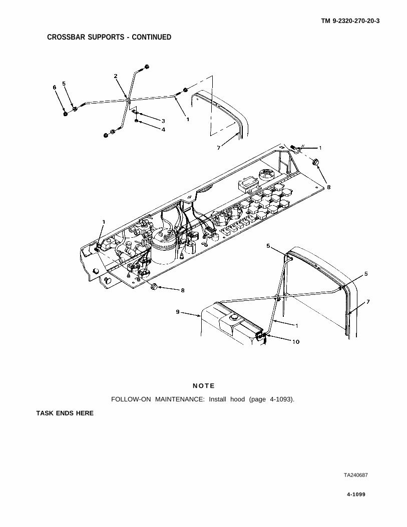
TM 9-2320-270-20-3
CROSSBAR SUPPORTS - CONTINUED
TASK ENDS HERE
N O T E
FOLLOW-ON MAINTENANCE: Install hood (page 4-1093).
TA240687
4-1099

TM 9-2320-270-20-3
RIGHT SIDE PANEL
This task covers:
a. Removal (page 4-1100) c. Inspection/Replacement (page 4-1 102)b. Cleaning (page 4-1102) d. Installation (page 4-1102)
INITIAL SETUP
Tools Materials/Parts – Continued
Handle, ratchet, 3/8-inch drive Lockwasher, hinge to right side panel (threeScrewdriver, cross-tip, number 2 required)Socket, deep, 1/2-inch, 3/8-inch drive Wrench, open-end, 3/8-inch Personnel Required
Materials/Parts One
Lockwasher, bracket to cab (tworequired)
Lockwasher, hinge to door (threerequired)
ACTIONLOCATION ITEM REMARKS
REMOVAL
1.
2.
3.
4.
5.
6.
Right side ofhood (1)
Front of vehicle
Mount (3)
Bracket (5) andsupport (6)
Bracket (5) tocab (8)
Cab (8)
Three latches (2)
Right side ofhood (1)
Latch (4)
Right side panel (7)
Two nuts (9),Iockwashers (10),and washers (11)
Bracket (5)
Unlatch.
Open.
Unlatch.
Lift, slide towards front of vehicle,and take out.
a. Using 1/2-inch socket and handle,unscrew and take off.
b. Get rid of Iockwashers (10).
Take off.
4-1100

TM 9-2320-270-20-3
RIGHT SIDE PANEL - CONTINUED
ACTIONLOCATION ITEM REMARKS
REMOVAL
7. Door (12)
8. Hinge (14) to rightside panel (7)
9. Right side panel (7)
10. Hinge (14) todoor (12)
11. Door (12)
Latch (13)
Three screws (15),washers (16), lock-washers (17), andnuts (18)
Hinge (14) anddoor (12)
Three screws (19),washers (20), lock-washers (21), andnuts (22)
Hinge (14)
Unlatch.
a. Using 3/8-inch wrench and cross-tipscrewdriver, unscrew and take out.
b. Get rid of Iockwashers (1 7).
Take off.
a. Using 3/8-inch wrench and cross-tipscrewdriver, unscrew and take out.
b. Get rid of Iockwashers (21).
Take off,
TA240688
4-1101

TM 9-2320-270-20-3
RIGHT SIDE PANEL - CONTINUED
ACTIONLOCATION ITEM REMARKS
CLEANING
12.
inspection/REPLACEMENT
13.
lNSTALIATION
14. Door (1)
15. Hinge (2) todoor (1)
16. Right sidepanel (7)
17. Hinge (2) toright sidepanel (7)
18. Door (1)
19. Cab (13)
20. Bracket (14)to cab (13)
21. Bracket (14) andsupport (17)
22. Mount (18)
23.
24. Right sidehood (20)
All parts
All parts
Hinge (2)
Three screws (3),washers (4), newIockwashers (5),and nuts (6)
Hinge (2) anddoor (1)
Three screws (8),washers (9), newIockwashers (10),and nuts (11)
Latch (12)
Bracket (14)
Two nuts (15) andnew Iockwashers (16)
Right side panel (7)
Latch (19)
Right side hood (20)
Three latches (21)
Clean according to general maintenanceinstructions (page 4-1).
Inspect according to general maintenanceinstructions (page 4-1).
Place in position with flat side againstdoor.
Screw in and tighten using 3/8-inchwrench and cross-tip screwdriver.
Place in position.
Screw in and tighten using 3/8-inchwrench and cross-tip screwdriver.
Latch.
Put on.
Screw in and tighten using l/2-inchsocket and handle.
Slide in place.
Latch.
Close.
Latch.
—
4-1102

TM 9-2320-270-20-3
RIGHT SIDE PANEL - CONTINUED
TASK ENDS HERE
TA240689
4-1103

TM 9-2320-270-0-3
LEFT SIDE PANEL AND BRACKETS
This task covers:
a. Removal (page 4-1104) c. Inspection/Replacement (page 4-1 106)b. Cleaning (page 4-1106) d. Installation (page 4-1106)
INITIAL SETUP
Tools
Handle, ratchet, 3/8-inch driveSocket, deep-well, 1/2-inch, 3/8-inch
driveSocket, 7/16-inch, 3/8-inch driveSocket, 9/16-inch, 3/8-inch driveWrench, open-end, 7/16-inchWrench, open-end, 1/2-inchWrench, open-end, 9/16-inch
Materials/Parts
Lockwasher, inner stop to air cleaner bracket(three required)
Lockwasher, pivot bracket to air cleanerbracket (two required)
Lockwasher, outer stop to air cleaner bracket(two required)
Personnel Required
One
Equipment Condition
Air cleaner filter removed (page 4-45).
ACTIONLOCATION ITEM REMARKS
REMOVAL
1. Left side hood (1) Two latches (2) Unlatch,
2. Mount (3) Latch (4) Unlatch.
3. Left side hood (1) Lift open.
4. Mount (5) Latch (6) Unlatch.
5. Pivot bracket (7) Left side panel (9) Lift, slide towards front of vehicle, andand support (8) take out.
4-1104

TM 9-2320-270-20-3
LEFT SIDE PANEL AND BRACKET - CONTINUED
ACTIONLOCATION ITEM REMARKS
6. Pivot bracket (7)to air cleanerbracket (10)
7. Air cleanerbracket (10)
8. Outer stop (15)to air cleanerbracket (10)
9. Air cleanerbracket (10)
10. Inner stop (20)to air cleanerbracket (10)
11. Air cleanerbracket (10)
Two screws (11),four washers (12),two Iockwashers(13), and nuts (14)
Pivot bracket (7)
Two screws (16),washers (17), lock-washers (18), andnuts (19)
Outer stop (15)
Three screws (21),six washers (22),three Iockwashers(23) and nuts (24)
Inner stop (20)
a. Using 7/16-inch socket, ratchet han-dle with 3/8-inch drive, and 7/16-inch wrench, unscrew and take out.
b. Get rid of Iockwashers (13).
Take off.
a. Using 1/2-inch socket, ratchet handlewith 3/8-inch drive, and 1/2-inchwrench, unscrew and take out.
b. Get rid of Iockwashers (18).
Take off.
a.
b.
Using 9/16-inch socket, ratchet han-dle with 3/8-inch drive, and 9/16-inch wrench, unscrew and take out.Get rid of Iockwashers (23).
Take off.
TA240690
4-1105

LEFT SIDE PANEL AND BRACKETS - CONTINUED
ACTIONLOCATION ITEM REMARKS
CLEANING
12.
INSPECTION/REPLACEMENT
13.
INSTALLATION
14. Air cleanerbracket (1)
15. inner stop (2)to air cleanerbracket (1)
16. Air cleanerbracket (1)
17. Outer stop (7)to air cleanerbracket (1)
18. Air cleanerbracket (1)
19. Pivot bracket (12)to air cleanerbracket (1)
20. Pivot bracket (12)support (17)
All parts Clean according to general maintenanceinstructions (page 4-1).
All parts inspect according to general maintenanceinstructions (page 4-1).
If side pane Is damaged, removelatches (page 4-1108) beforereplacing It.
inner stop (2)
Three screws (3),six washers (4),three new iock-washers (5), andnuts (6)
Outer stop (7)
Two screws (8),washers (9), newIockwashers (10),and nuts (11)
Pivot bracket (12)
Two screws (13),four washers (14),two new lock-washers (15), andnuts (16)
Left sidepanel (18)
Put on.
Screw in and tighten using 9/16-inchsocket, ratchet handle with 3/8-inchdrive, and 9/16-inch wrench.
Put on.
Screw in and tighten using 1/2-inchsocket, ratchet handle with 3/8-inchdrive, and 1/2-inch wrench.
Put on.
Screw in and tighten using 7/16-inchsocket, ratchet handle with 3/8-inchdrive and 7/16-inch wrench.
Slide in position.
4-1108
T M 9 - 2 3 2 0 - 2 7 0 - 2 0 - 3

TM 9-2320-270-20-3
LEFT SIDE PANEL AND BRACKETS - CONTINUED
LOCATION ITEMACTION
REMARKS
21. Mount (19)
22.
23. Mount (22)
24. Left side ofhood (21)
Latch (20)
Left side ofhood (21)
Latch (23)
Two latches (24)
Latch.
Close.
Latch.
Latch.
N O T E
FOLLOW-ON MAINTENANCE: Install air cleaner filter (page 4-45).
TASK ENDS HERE
TA240691
4-1107

TM 9-2320-270-20-3
LATCHES, LATCH MOUNTING BRACKETS, AND CATCHES
This task covers:
a. Latch Removal (page 4-1108) e. Inspection/Replacement (page 4-111 1).b. Latch Mounting Bracket Removal f. Catch Installation (page 4-1111)
(page 4-1 109) g. Latch Mounting Bracket Installationc. Catch Removal (page 4-1110) (page 4-1112).d. Cleaning (page 4-1111) h. Latch installation (page 4-1113).
INITIAL SETUP
Tools Materials/Parts
Drill, electric, portable Lockwasher (as required)Drill twist, 1 1/64-inch Pin, cotter (as required)Hammer, machinist’s ball-peen Rivets (as required)Pliers, slip-jointPunch, drive pin, 3/16-inch Personnel RequiredRiveter, handWrench, open-end, 3/8-inch OneWrench, open-end, 1/2-inch
ACTIONLOCATION ITEM REMARKS
LATCH REMOVAL
N O T E
There are nine latches on this vehicle, Do steps 1 thru 7 to remove any latch.
1. Catch (1) Latch (2) Unlatch.
2. Pin (3) Cotter pin (4) a. Using pliers, take out.b. Get rid of.
3. Latch (2) to Pin (3) Take out.mount (5)
4. Mount (5) Latch (2) Take off.
5. Mount (5) to Three rivets (7) a. Using hammer and drive pin punch,hood (6) mark center.
b. Using electric drill and drill twist, drillout.
6. Three rivets (7) andcollars (8)
a. Take out.b. Get rid of rivets (7).
4-1108

TM 9-2320-270-20-3
LATCHES, LATCH MOUNTING BRACKETS, AND CATCHES - CONTINUED
ACTIONLOCATION ITEM REMARKS
7. Hood (6) Mount (5) and Take off.spacer (9)
LATCH MOUNTING BRACKET REMOVAL
N O T E
There are three latch mounting brackets on vehicle. Do steps 8 and 9 to remove hoodlatch mounting bracket. Do steps 12 and 13 to remove either side panel latch mountingbracket.
8. Bracket (10) to Two nuts (12), a. Using 3/8-inch wrench, unscrew andcab (11) Iockwashers (13) and take out.
washers (14) b. Get rid of Iockwashers (13).
9. Cab (11) Bracket (10) Take off.
TA240692
4-1109

TM 9-2320-270-20-3
LATCHES, LATCH MOUNTING BRACKETS, AND CATCHES - CONTINUED
ACTIONLOCATION ITEM REMARKS
LATCH MOUNTING BRACKET REMOVAL - CONTINUED
10. Clamp (1) Screw (2) and lock-washer (3)
11. Bracket (4) Clamp (1) andhose (5)
12 Bracket (4) to Screw (7), lock-support (6) washer (8), and
washer (9)
13. Support (6) Bracket (4)
a. Using 1/2-inch wrench, unscrew andtake off.
b. Get rid of Iockwasher (3).
Lift off.
a. Using 1/2-inch wrench, unscrewand take out.
b. Get rid of lockwashers (8).
Take off.
There are nine catches on the vehicle. Do steps 14 thru 16 to remove any catch.
14. Catch (10) to Three rivets (12) a. Using hammer and drive pin punch,hood (11) mark center of rivets (12).
b. Using electric drill and drill twist, driilout.
15. Three rivets (12) a. Take out.and collars (13) b. Get rid of rivets (12).
TA240693
4-1110
N O T E

TM 9-2320-270-20-3
LATCHES, LATCH MOUNTING BRACKETS, AND CATCHES - CONTINUED
ACTIONLOCATION ITEM REMARKS
16. Hood (11) Catch (10) and Take off.spacer (14)
CLEANING
17. All parts Clean according to general maintenanceinstructions (page 4-1).
inspection/REPLACEMENT
18. All parts Inspect according to general maintenanceinstructions (page 4-1).
CATCH INSTALLATION
N O T E
There are nine catches on the vehicle. Do steps 19 and 20 to install any catch.
19. Hood (11) Catch (10) andspacer (14)
20. Catch (10) to Three new rivetshood (11) (12) and
collars (13)
Put on.
Using hand riveter, put in.
TA240694
4-1111

TM 9-2320-270-20-3
LATCHES, LATCH MOUNTING BRACKETS, AND CATCHES - CONTINUED
ACTIONLOCATION ITEM REMARKS
LATCH MOUNTING BRACKET INSTALLATION
N O T E
There are three latch mounting brackets on vehicle. Do steps 21 and 22 to install eitherside panel latch mounting bracket. Do steps 25 and 26 to install hood latch mountingbracket.
21. support (1) Bracket (2) Put on.
22. Bracket (2) to Screw (3), new lock- Screw in and tighten using 1/2-inchsupport (1) washer (4), and wrench.
washer (5)
23. Bracket (2) Hose (6) and Place in position.clamp (7’)
24. Clamp (7) Screw (8) and Screw in and tighten using 1/2-inchIockwasher (9) wrench.
25. Cab (10) Bracket (11) Put in position.
26. Bracket (11) to Two nuts (12), new Screw in and tighten using 3/8-inchcab (10) Iockwashers (13), wrench.
and washers (14)
TA240695
4-1112

LATCHES, LATCH MOUNTING BRACKETS, AND CATCHES - CONTINUED
ACTIONLOCATION ITEM REMARKS
LATCH INSTALLATION
N O T E
There are nine latches on the vehicle. Do steps 27 thru 32 to install any latch.
27. Hood (15) Mount (16) and Put on.spacer (17)
Three new rivets Using hand riveter, Put in.(18) andcollars (19)
28. Mount (16) tohood (15)
TA240696
4-1113
TM9-23420-270-20-3

TM 9-2320-270-20-3
LATCHES, LATCH MOUNTING BRACKETS, AND CATCHES - CONTINUED
ACTIONLOCATION ITEM REMARKS
LATCH INSTALUTION - CONTINUED
29. Mount (1) Latch (2) Put on.
30. Latch (2) to Pin (3) Put in.mount (1)
31. Pin (3) New cotter pin (4) Put in.
32 Catch (5)
TASK ENDS HERE
INSULATION
Latch (2) Latch.
This task covers:
a. Removal (page 4-1115)b. installation (page 4-1115)
lNITIAL SETUP
Tools Materials/Parts – Continued
Brush, acid swabbing insulation, side panel (L. H.)Knife, putty insulation, side panel (R. H.)
insulation, side panel door (R. H.)Materials/Parts
Personnel RequiredAdhesive (item 1, appendix C)insulation, hood (C. H.) Oneinsulation, hood (R. H.)
TA240697
4-1114

TM 9-2320-270-20-3
INSULATION - CONTINUED
ACTIONLOCATION ITEM REMARKS
REMOVAL
N O T E
Use this procedure to replace any insulation on vehicle. Left side insulation is shown.
1. Engine compartment Left side panel Remove (page 4-1 104).
2. Left side panel (1) Insulation (2) a.b.
INSTALLATION
3. Left side panel (1) Insulation (2) a.
b.
c.
Using knife, scrape off.Get rid of.
Using brush, apply thin coat ofadhesive.Center above panel (1) and press intoplace.Let adhesive set for five minutes.
4. Engine compartment Left side panel Install (page 4-1104).
TASK ENDS HERE
TA240698
4-1115

TM 9-2320-270-20-3
VENTILATOR
This task covers:
a. Removal (page 4-1116) c. Inspection/Replacement (page 4-1 116)b. Cleaning (page 4-1116) d. Installation (page 4-1117)
INITIAL SETUP
Tools Materials/Parts
Screwdriver, cross-tip, number 3 LockwasherHandle, ratchet, 3/8-inch driveExtension, 3/8-inch drive, 6-inch Personnel RequiredSocket, 3/8-inch, 3/8-inch driveSocket, 9/16-inch, 3/8-inch drive OneWrench, open-end, 9/16-inch
ACTIONLOCATION ITEM REMARKS
REMOVAL
1. Cab (1) and brace(2) to bracket (3)
Screw (4), lock-washer (5), andnut (6)
2. Bracket (3) to Three screws (8)ventilator (7)and cab (1)
3. Ventilator(7) Bracket (3)
4. Ventilator (7) Eight screws (9)to cab (1)
5. Cab (1) Ventilator (7)
CLEANING
6. All parts
inspection/REPLACEMENT
7. All parts
a.
b.c.
Using 9/16-inch socket, handle, andwrench, unscrew and take out.Get rid of Iockwasher (5).Swing brace (2) out of the way.
Using 3/8-inch socket, extension andhandle, unscrew and take out.
Take off.
Using screwdriver, unscrew and take out.
Take off.
Clean according to general maintenanceinstructions (page 4-1).
Inspect according to general maintenanceinstructions (page 4-1).
4-1116

VENTILATOR - CONTINUED
ACTIONLOCATION ITEM REMARKS
INSTALLATION
8. Cab (1)
9. Ventilator (7)to cab (1)
10. Ventilator (7)
11. Bracket (3) toventilator (7)and cab (1)
12. Bracket (3)
13. Brace (2) tobracket (3)
Ventilator (7)
Eight screws (9)
Bracket (3)
Three screws (8)
Brace (2)
Screw (4), newIockwasher (5),and nut (6)
Put in position.
Screw in and tighten using screwdriver.Do not put screws into the threefront holes.
Put on.
Screw in and tighten using 3/8-inchsocket, extension and handle,
Put on.
Screw in and tighten using 9/16-inchsocket, handle, and wrench.
TASK ENDS HERE
TA240699
4-1117
TM9-2320-270-20-3

TM 9-2320-270-20-3
GRAB HANDLE
This task covers:
a. Removal (page 4-1118) c. inspection/Replacement (page 4-1 118)b. Cleaning (page 4-1118) d. Installation (page 4-1118)
INITIAL SETUP
Tools Materials/Parts
Handle, ratchet, 3/8-inch drive Lockwasher (two required)Socket, 9/16-inch, 3/8-inch driveWrench, open-end, 9/16-inch Personnel Required
One
ACTIONLOCATION ITEM REMARKS
REMOVAL
1. Grab handle (1)to cab (2)
2. Cab(2)
CLEANING
3.
INSPECTION/REPLACEMENT
4.
INSTALLATION
5. Cab(2 )
6. Grab handle (1)to cab (2)
Two screws (3),lockwashers (4),and nuts (5)
Grab handle (1)
All parts
Ail parts
Grab handle (1)
Two screws (3),new Iockwashers(4), and nuts (5)
a. Using socket, handle, and wrench, unscrew and take out.
b. Get rid of Iockwashers (4).
Take off.
Clean according to general maintenanceinstructions (page 4-1).
Inspect according to general maintenanceinstructions (page 4-1).
Put on.
Screw in and tighten using socket, handle,and wrench.
4-1118

TM 9-2320-270-20-3
GRAB HANDLE - CONTINUED
TASK ENDS HERE
SPLASH SHIELDS
This task covers:
a. Removal (page 4-1120) c. Inspection/Replacement (page 4-1 120)b. Cleaning (page 4-1120) d. Installation (page 4-1120)
INITIAL SETUP
Tools Materials/Parts - Continued
Handle, ratchet, 1/2-inch drive Lockwasher (four required for each splashSocket, 1/2-inch, 1/2-inch drive shield)Socket, 15/16-inch, 1/2-inch driveWrench, open-end, 15/16-inch Personnel RequiredWrench, open-end, `1/2-inch
OneMaterials/Parts
Locknut (three required for eachsplash shield)
TA240700
4-1119

TM 9-2320-270-20-3
SPLASH SHIELDS - CONTINUED
ACTIONLOCATION ITEM REMARKS
N O T E
Use this procedure to replace either splash shield. Left side splash shield is shown.
REMOVAL
1. Plate (1) to shield(2) and angle (3)
2. Angie (3)
3. Angle (3) toframe (7)
4. Frame (7)
CLEANING
5.
INSPECTION/REPLACEMENT
6.
INSTALLATION
7. Frame(7)
8. Angie (3) toframe (7)
9. Angie (3)
Four screws (4),lockwashers (5),and nuts (6)
Plate (1) andshield (2)
Three screws (8),six washers (9), andthree locknuts (10)
Angie (3)
All parts
All parts
Angie (3)
Three screws (8),six washers (9),and three newlocknuts (10)
Shield (2) andplate (1)
a. Using 1/2-inch socket, handle, and1/2-inch wrench, unscrew and takeout.
b. Get rid of lockwashers (5).
Take off.
a. Using 15/16-inch socket, handle, and15/16-inch wrench, unscrew and takeout.
b. Get rid of locknuts (10).
Take off.
Clean according to general maintenanceinstructions (page 4-1).
inspect according to general maintenanceinstructions (page 4-1).
Put on.
Screw in and tighten using 15/16-inchsocket, handle, and 15/16-inch wrench.
Put on.
4-1120

SPLASH SHIELDS - CONTINUED
ACTIONLOCATION ITEM REMARKS
10. Plate (1) to shield Four screws (4), new Screw in and tighten using 1/2-inch(2) and angle (3) Iockwashers (5), and socket, handle, and 1/2-inch wrench.
nuts (6)
TASK ENDS HERE
TA240701
4-1121
TM9-2320-270-20-3

TM 9-2320-270-20-3
VISORS
This task covers:
a. Removal (page 4-1122) c. installation (page 4-1122)b. Cleaning/Inspection (page 4-1122)
INITIAL SETUP
Tools Personnel Required
Screwdriver, cross-tip, number 3 One
ACTIONLOCATION ITEM REMARKS
N O T E
There are two visors in vehicle. Use this procedure to replace either visor.
REMOVAL
1. Visor (1) to cab (2) Two screws (3) Using screwdriver, unscrew and take out.
2. Cab (2) Visor (1) Take off.
CLEANING/INSPECTION
3. All parts Clean and inspect as shown in the generalmaintenance instructions (page 4-1).
INSTALLATION
4. Cab (2) Visor (1) Put on cab (2).
5. Visor(1) to cab (2) Two screws (3) Screw in and tighten using screwdriver.
4-1122

VISORS - CONTINUED
TASK ENDS HERE
ASHTRAY
TM 9-2320-270-20-3
This task covers:
Removal (page 4-1 124)c. Installation (page 4-1124)Cleaning/Inspection (page 4-1 124)
ToolsPersonnel Required
Screwdriver, cross-tip, number 2One
TA240702
4-1123
a. b.

TM 9-2320-270-20-3
ASHTRAY - CONTINUED
ACTION —
LOCATION I T E M REMARKS
REMOVAL
1. Carrier (1)
2. Carrier (1) toinstrument panel (3)
3. Instrument panel (3)
CLEANING/inspect ion
4.
INSTALLATION
5. Instrument panel (3)
6. Carrier (1) to
Ashtray (2) Slide out until it hits stop, bend downslightly and slide out.
Four screws (4) Using screwdriver, unscrew and take out.
Carrier (1) Take off.
All parts Clean and inspect as shown in the generalmaintenance instructions (page 4-1).
Carrier (1) Put on.
Four screws (4) Screw in and tighten using screwdriver.instrument panel (3)
7. Carrier (1) Ashtray (2) Slide in until it hits stop, bend downslightly and slide in.
TASK ENDS HERE
TA240703
4-1124

TM 9-2320-270-20-3
PASSENGER’S SEAT
This task covers:
a. Removal (page 4-1125) c. Installation (page 4-1126)b. Cleaning/Inspection (page 4-1126)
INITIAL SETUP
Tools
Handle, ratchet, 3/8-inch driveSocket, 9/16-inch, 3/8-inch driveWrench, open-end, 9/16-inch
Materials/Parts
Lockwasher (four required)
Personnel Required
Two
ACTIONLOCATION ITEM REMARKS
REMOVAL
1. Seat (1) to cabfloor (2)
2. Cab floor (2)
Four screws (3),washers (4), lock-washers (5), andnuts (6)
Seat (1)
a. With help from assistant and usingsocket, handle, and wrench, unscrewand take out.
Note location of longer screw.b. Get rid of Iockwashers (5).
Take off.
TA240704
4-1125

TM 9-2320-270-20-3
PASSENGER’S SEAT - CONTINUED
ACTIONLOCATION ITEM REMARKS
CLEANING/I NSPECTION
3. All parts Clean and inspect as shown in the generalmaintenance instructions (page 4-1).
INSTALLATION
4. Cab floor (1) Seat (2) Put on.
5. Seat (2) to cab Four screws (3), a.floor (1) washers (4), new b.
Iockwashers (5),and nuts (6)
Note location of longer screw (3).With help form assistant, screw in andtighten using socket, handle, andwrench.
TASK ENDS HERE
4-1126
TA240705

TM 9-2320-270-20-3
DRIVER’S SEAT AND SUPPORT
This task covers:
a. Removal (page 4-1128) c. Installation (page 4-1128)b. Cleaning/Inspection (page 4-1128)
INITIAL SETUP
Tools
Handle, ratchet, 3/8-inch driveSocket, 7/16-inch, 3/8-inch driveSocket, 1/2-inch, 3/8-inch driveWrench, open-end, 7/16-inchWrench, open-end, 1/2-inch
Materials/Parts – Continued
Lockwasher, support to cab floor (threerequired)
Personnel Required
TwoMaterials/Parts
Equipment ConditionLockwasher, brace to support (four
required)Lockwasher, jumper (two required)Lockwasher, seat to support (four
required)
Driver’s seat belts removed (page 4-1 130).Fire extinguisher removed
(TM 9-2320-270-10).
4-1127

TM 9-2320-270-20-3
DRIVER’S SEAT AND SUPPORT - CONTINUED
ACTIONLOCATION ITEM REMARKS
REMOVAL
1. Seat (1) tosupport (2)
a. Using 1/2-inch wrench, unscrew andtake out.
b. Get rid of Iockwashers (4).
Take off.
Four nuts (3),Iockwashers (4),and washers (5)
2. support (2) Seat (1) and twospacers (6)
3. Brace (7) tosupport (2)
Four screws (8),washers (9), lock-washers (10), andnuts (11)
Using 7/16-inch socket, handle, and7/16-inch wrench, unscrew and takeout.Get rid of Iockwashers (10).
Using 1/2-inch socket, handle, and1/2-inch wrench, unscrew and take out.Get rid of Iockwashers(15).
a.
b.
a.
b.
a.
b.
a.
b.
4. support (2) tocab floor (12)
Screw (13),washer (14), twoIockwashers (1 5),jumper (16), andnut (17)
5. Screw (18),washer (19), twoIockwashers (20),and nut (21)
Using 1/2-inch socket, handle, and1/2-inch wrench, unscrew and take out.Get rid of Iockwashers (20).
With help from assistant and using1/2-inch socket, handle, and 1/2-inchwrench, unscrew and take out.Get rid of Iockwashers (24).
6. Two screws (22),washers (23), lock-washers (24), andnuts (25)
7. Cab floor (12)
CLEANING/inspect ion
8.
support (2) Take off.
All parts Clean and inspect as shown in the generalmaintenance instructions (page 4-1).
INSTALLATION
9. Cab floor (12)
10. support (2) tocab floor (12)
support (2) Place in position.
Two screws (22), With help from assistant, screw in andwashers (23), new tighten using 1/2-inch socket, handle,Iockwashers (24), and 1/2-inch wrench.and nuts (25)
4-1128

TM9-2320-270-20-3
DRIVER’S SEAT AND SUPPORT - CONTINUED
ACTIONLOCATION ITEM REMARKS
11. Screw (18), Screw in and tighten using 1/2-inchwasher (19), two socket, handle, and 1/2-inch wrench.new Iockwashers(20), and nut (21)
12.
13. Brace (7) tosupport (2)
14. support (2)
15. Seat (1) tosupport (2)
Screw (13), Screw in and tighten using 1/2-inchwasher (14), two socket, handle, and 1/2-inch wrench.new Iockwashers(15), jumper (16),and nuts (17)
Four screws (8),washers (9), newIockwashers (10),and nuts (11)
Seat (1) and twospacers (6)
Four nuts (3),new Iockwashers (4),and washers (5)
Screw in and tighten using 7/16-inchsocket, handle, and 7/16-inch wrench.
Place in position.
Screw on and tighten using 1/2-inchwrench.
TA240706
4-1129

DRIVER’S SEAT AND SUPPORT - CONTINUED
INSTALLATION – CONTINUED
N O T E
FOLLOW-ON MAINTENANCE:
1. Install fire extinguisher (TM 9-2320-270-10).2. Install driver’s seat belts (page 4-1130).
TASK ENDS HERE
SEAT BELTS
This task covers:
a. Driver’s Seat Belt Removal d. Passenger’s Seat Belt Installation(page 4-1130) (page 4-1132)
b. Passenger’s Seat Belt Removal e. Driver’s Seat Belt Installation (page 4-1132)(page 4-1132)
c. Cleaning/Inspection (page 4-1132)
INITIAL SETUP
Tools Materials/Parts - Continued
Pliers, slipjoint, straight-nose Lockwashers (as required)Wrench, adjustable, 10-inchWrench, open-end, 11/16-inch Personnel RequiredWrench, open-end, 5/8-inch
TwoMaterials/Parts
Cotter pin (as required)
ACTIONLOCATION ITEM REMARKS
DRIVER’S SEAT BELT REMOVAL
1.
N O T E
Driver’s seat has two seat belts fastened to each side. Both sides are removed the sameway. Left side seat belts are shown.
Driver’s seat (1) Nut (3) and a. Using 11/16-inch and 5/8-inchpost (2) Iockwasher (4) wrenches, unscrew and take off.
b. Get rid of Iockwasher (4).
4-1130
TM9-2320-270-20-3

SEAT BELTS - CONTINUED
ACTIONLOCATION ITEM REMARKS
2. Driver’s seat (1) Post (2) and twoseat belts (5) and (6)
3. Post (2) Seat belt (5)
4. Cotter pin (7) andseat belt (6)
5. Seat belt (5)
6. Anchor bolt (9)
7. Cab (10)
Cotter pin (8)
Seat belt (5)
Anchor bolt (9),washer (11), lock-washer (12), andnut (13)
Take out.
Slide off.
a.b.c.
a.
b.
Using pliers, take out pin (7).Get rid of pin (7).Open seat belt (6) and take off.
Using pliers, bend ends together andtake out.Get rid of.
Open and take off.
a.
b.
With help from assistant and using11/16-inch and adjustable wrenches,unscrew and take out.Get rid of Iockwasher (12).
TA240707
4-1131
TM9-2320-270-20-3

TM9-2320-270-20-3
SEAT BELTS - CONTINUED
ACTIONLOCATION ITEM REMARKS
PASSENGER’S SEAT BELT REMOVAL
N O T E
There are four seat belts for passenger’s seat. Each seat belt is removed the same way.Right side seat belt is shown.
8. Seat belt (1) Cotter pin (2) a. Using pliers, take out.b. Get rid of.
9. Anchor bolt (3) Seat belt (1) Open and take off.
10. Cab (4) Anchor bolt (3), a. With help from assistant and usingwasher (5), lock- 11/16-inch and adjustable wrenches,washer (6), and unscrew and take out.nut (7) b. Get rid of Iockwasher (6).
CLEANING/inspect ion
11. All parts Clean and inspect as shown in the generalmaintenance instructions (page 4-1).
PASSENGER’S SEAT BELT INSTALLATION
N O T E
There are four seat belts for passenger’s seat. Each seat belt is installed the same way.Right side seat belt is shown.
12. Cab (4) Anchor bolt (3), With help from assistant, screw in andwasher (5), new tighten using 11/16-inch and adjustablelockwasher (6), wrenches.and nut (7)
13. Anchor bolt (3) Seat belt (1) Put on and close.
14. Seat belt (1) New cotter pin (2) Put into seat belt (1) and bend ends outusing pliers.
DRIVER’S SEAT BELT INSTALLATION
N O T E
Driver’s seat has two seat belts fastened to each side. Both sides are installed the sameway. Left side seat belts are shown.
4-1132

TM9-2320-270-20-3
ACTIONLOCATION ITEM REMARKS
15. Cab (4) Anchor bolt (8), Screw in and tighten using 11/16-inchwasher (9), new adjustable wrenches.Iockwasher (10),and nut (11)
16. Anchor bolt (8) Seat belt (12) Put on and close.
17. Seat belt (12) New cotter pin (13) Using pliers, put in.
18. Post (14) Seat belt (15) Slide on post.
19. Seat belt (15) New cotter pin (16) Using pliers, put in.
20. Post (16) Seat belt (12) Slide on.
21. Driver’s seat (17) Post (14) and two Put in.
22. Post (14)
seat belts (12)and (15)
Nut (18) and new Screw on and tighten using 11/16-inchlockwasher (19) 5/8-inch wrenches.
TASK ENDS HERETA240708
4-1133

TM9-2320-270-20-3
FLOOR MAT
This task covers:
a. Removal (page 4-1134) c. Installation (page 4-1134)b. Cleaning/Inspection (page 4-1134)
INITIAL SETUP
Tools Equipment Condition
Screwdriver, cross-tip, number 3 Brake pedal and treadle valve removed(page 4-720).
Personnel Required Accelerator pedal removed (page 4-126).Retarder pedal removed (page 4-547).
One Shift control removed (page 4-526).Shift control housing removed (page 4-536).
ACTIONLOCATION ITEM REMARKS
REMOVAL
1. Two plates (1) tocab (2)
2. Cab (2)
CLEANING/inspect ion
3.
i n s t a l l a t i o n
4. Cab (2)
5. Two plates (1)to cab (2)
10 screws (3)
Two plates (1)and floor mat (4)
Ail parts
Floor mat (4) andtwo plates (1)
10 screws (4)
Using screwdriver, unscrew and take out.
Take off.
Clean and inspect as shown in the generalmaintenance instructions (page 4-1).
Place in position.
Screw in and tighten using screwdriver.
4-1134

TM9-2320-270-20-3
FLOOR MAT - CONTINUED
N O T E
FOLLOW-ON MAINTENANCE:
1. Install shift control housing (page 4-538).2. Install shift control (page 4-526).3. Install retarder pedal (page 4-547).4. Install accelerator pedal (page 4-126).5. Install brake pedal and treadle valve (page 4-720).
TASK ENDS HERE
Section XVII. WINCHES
Page Page
Hydraulic Oil Filter . . . . . . . . . . . . . . . . . . . . . . . . . . . . . . . . . . . . . . . 4-1172 Winch Control Valve . . . . . . . . . . . . . . . . . . . . . . . . . . . . . . . . . . . 4-1157Hydraulic Reservoir . . . . . . . . . . . . . . . . . . . . . . . . . . . . . . . . . . . . . . 4-1163 Winch Hydraulic Valves 4-1155Hydraulic Reservoir Draining and
. . . . . . . . . . . . . . . . . . . . . . . . . . . . .Winch Propeller Shaft . . . . . . . . . . . . . . . . . . . . . . . . . . . . . . . . 4-1175
Filling . . . . . . . . . . . . . . . . . . . . . . . . . . . . . . . . . . . . . . . . . . . . . . . . . . . . . . . . 4-1160 Winch Throttle Valve . . . . . . . . . . . . . . . . . . . . . . . . . . . . . . . . . . 4-1141Pump to Winch Valves Winch Valves to Motors
Hydraulic Lines . . . . . . . . . . . . . . . . . . . . . . . . . . . . . . . . . . . . . . . . 4-1150 Hydraulic Lines . . . . . . . . . . . . . . . . . . . . . . . . . . . . . . . . . . . . . . 4-1146Winch . . . . . . . . . . . . . . . . . . . . . . . . . . . . . . . . . . . . . . . . . . . . . . . . . . . . . . . . . . . . . 4-1136Winch Cable . . . . . . . . . . . . . . . . . . . . . . . . . . . . . . . . . . . . . . . . . . . . . . . . . . 4-1140
TA240709
4-1135

TM9-2320-270-20-3
WINCH
This task covers:
a. Removal (page 4-1136)b. Installation (page 4-1138)
INITIAL SETUP
Tools Materials/Parts – Continued
Chain Lockwashers, winch base (four required)Extension, 5-inch, 3/4-inch drive Packing, preformed, hoses (two required)Handle, ratchet, 3/4-inch drive Tag, marking (item 18, appendix C)Lifting equipment Tape, teflon (item 22, appendix C)Socket, 1 1/2-inch, 3/4-inch driveWrench, open-end, 9/16-inch Personnel Required Wrench, open-end, 5/8-inchWrench, open-end, 1 1/2-inch TwoWrench, pipe, 12-inch
Equipment ConditionMateriais/Parts
Winch cable removed (page 4-1140).Hose plugs Pusher axle tire removed (TM 9-2320-270-10).Lockwashers, hose clamp (eight
required)
ACTIONLOCATION ITEM REMARKS
REMOVAL
1. Two hose clamps (1) Four screws (2) and a. Using 5/8-inch wrench, unscrew andIockwashers (3) take off.
b. Get rid of lockwashers (3).
2. Hydraulic motor (4) Two hose clamps (1), a. Pull off.hose (5), and b. Get rid of packing (6).packing (6) c. Plug hose (5).
There are two hose ports on motor.Repeat steps 1 and 2 to remove otherhose.
3. Tee (7)
N O T E
Tag lines according to general maintenance instructions (page 4-1).
Hose (8) Using 9/16-inch wrench, unscrew and pulloff.
4-1136

WINCH - CONTINUED
ACTIONLOCATION ITEM REMARKS
4. Hose (9) Using 9/16-inch wrench, unscrew and pulloff.
W A R N I N G
Some parts are heavy. Be careful when handling them. Lifting equipment is neededwhen parts weigh over 50 pounds (23 kg) for a single person lift, over 100 pounds(45 kg) for a two person lift, and over 150 pounds (68 kg) for a three or more personlift. Do not try to handle heavy parts without lifting equipment. Keep clear of heavy partssupported only by lifting equipment. Failure to observe this precaution could causeserious injury or death of personnel.
5. Winch base (10)
6.
Eight screws (11), a.Iockwashers (12),and nuts (13)
b.
Winch (14) a.b.
With help from assistant and using1 1/2-inch open-end wrench, socket,handle, and extension, unscrew andtake off.Get rid of Iockwashers (12).
Attach lifting equipment.Using lifting equipment, take out.
TA240710
4-1137
TM9-2320-270-20-3

TM9-2320-270-20-3
WINCH - CONTINUED
ACTIONLOCATION ITEM REMARKS
INSTALLATION
W A R N I N G
Some parts are heavy. Be careful when handling them. Lifting equipment is neededwhen parts weigh over 50 pounds (23 kg) for a single person lift, over 100 pounds(45 kg) for a two person lift, and over 150 pounds (68 kg) for a three or more personlift. Do not try to handle heavy parts without lifting equipment. Keep clear of heavy partssupported only by lifting equipment. Failure to observe this precaution could causeserious injury or death of personnel.
7. Winch base (1)
8.
9. Tee (6)
10.
11. Hydraulic motor (9)
12.
13. Two hose clamps (12)
Winch (2)
Eight screws (3),new lockwashers (4),and nuts (5)
Hose (7)
Hose (8)
New packing (10) andhose (11)
Two hose clamps (12)
Four screws (13) andnew lockwashers (14)
a. Attach lifting equipment.b. Using lifting equipment, place in
position.
With help from assistant, screw on andtighten using 1 1/2-inch wrench, socket,handle, and extension.
a. Wrap threads with teflon tape(page 4-1).
b. Screw on and tighten using 9/16-inchwrench.
Screw on and tighten using 9/16-inchwrench.
a. Remove plug.b. Place in position.
Place in position.
Screw in and tighten using 5/8-inchwrench.
There are two port hoses to motor.Repeat steps 11 to 13 for otherhose.
4-1138

TM9-2320-270-20-3
WINCH - CONTINUED
N O T E
FOLLOW-ON MAINTENANCE:
1. Install pusher axle tire (TM 9-2320-270-10).2. Install winch cable (page 4-1140).
TASK ENDS HERE
TA240711
4-1130

TM9-2320-270-20-3
WINCH CABLE
This task covers:
a. Removal (page 4-1140)b. Installation (page 4-1140)
INITIAL SETUP
Tools Personnel Required
Wrench, open-end, 1 1/8-inch One
ACTIONLOCATION ITEM REMARKS
REMOVAL
W A R N I N G
Leather gloves must be worn when handling cable to prevent cuts and scrapes. Never letcable run through hands.
1. Winch drum (1)
2.
INSTALLATION
3. Winch drum (1)
4.
Broken and frayed wires can cause injury.
Cable (2) Operate winch (TM 9-2320-270-10) andunwind all cable from drum.
Two nuts (3) and a.U-bolt (4)
b.
Two nuts (3) and a.U-bolt (4) b.
c.
Using 1 1/8-inch wrench, unscrew andtake out.Take off cable (2).
Put U-bolt (4) in holes and start nuts.Put cable end under U-bolt (4).Using 1 1/8-inch wrench, screw on andtighten.
W A R N I N G
Leather gloves must be worn when handling cable to prevent cuts and scrapes. Never letcable run through hands. Broken and frayed wires can cause injury.
Cable (2) Operate winch (TM 9-2320-270-10) andwind cable onto drum.
4-1140

TM9-2320-270-20-3
WINCH CABLE- CONTINUED
TASK ENDS HERE
WINCH THROTTLE VALVE
This task covers:
a. Removal (page 4-1142)b. Installation (page 4-1144)
INITIAL SETUP
Tools
Hammer, plasticWrench, open-end, 1/2-inchWrench, open-end, 5/8-inch
Materials/Parts
Lockwashers (12 required)Lockwashers, valve bracket (two required)Tag, marking (item 18, appendix C)Tape, teflon (item 22, appendix C)
Personnel Required
One
Equipment Condition
Air system drained (TM 9-2320-070-10).
TA240712
4-1141

TM9-2320-270-20-3
WINCH THROTTLE VALVE - CONTINUED
ACTIONLOCATION ITEM REMARKS
REMOVAL
1. Winch control 12 screws (2), a. Using 1/2-inch wrench, unscrew andpanel (1) Iockwashers (3), take out.
and washers (4) b. Get rid of Iockwashers (3).
2. Front cover Take off.plate (5)
Make sure all pressure is drained from air system before disconnecting air lines. Partsunder pressure can, when removed, fly off with great force causing injury to personnel.
N O T E
Tag lines according to general maintenance instructions (page 4-1).
3. Elbow (6) Hose (7) Using 5/8-inch wrench, unscrew and takeoff.
4. Elbow (6) or Insert (8) Pull out.hose (7)
5. Elbow (9) Hose (10) Using 5/8-inch wrench, unscrew and takeoff.
6. Elbow (9) or Insert (11) Pull out.hose (10)
7. Bracket (12) Two screws (13), a.Iockwashers (14),and nuts (15) b.
Two screws (17) and a.Iockwashers (18)
b.
8. Winch throttlevalve (16)
Using 1/2-inch wrench, unscrew andtake off.Get rid of Iockwashers (14).
Using 1/2-inch wrench, unscrew andtake off.Get rid of Iockwashers (18).
4-1142
W A R N I N G

TM9-2320-270-20-3
WINCH THROTTLE VALVE - CONTINUED
ACTIONLOCATION ITEM REMARKS
9. Winch control Bracket (12) Take off.panel (1)
10. Winch throttle Take out.valve (16)
11. Winch throttlevalve (16)
Two elbows (6) Using 5/8-inch wrench, unscrew and takeand (9) out.
TA240713
4-1143

WINCH THROTTLE VALVE - CONTINUED
ACTIONLOCATION ITEM REMARKS
INSTALLATION
12. Winch throttlevalve (1)
13. Elbow (2)
14. Winch throttlevalve (1)
15. Elbow (4)
16. Winch controlpanel (6)
17. Winch controlpanel (6)
18. Bracket (7)
19. Winch controlvalve (1)
20. Elbow (2)
21. Elbow (4)
22. Winch controlpanel (6)
23. Front coverplate (15)
Elbow (2)
Insert (3)
Elbow (4)
insert (5)
Winch throttlevalve (1)
Bracket (7)
Two screws (8), newIockwashers (9), andnuts (10)
Two screws (11) andnew iockwashers (12)
Hose (13)
Hose (14)
Front coverplate (15)
12 screws (16), newIockwashers (17),and washers (18)
a.
b.
Wrap threads with teflon tape(page 4-1).Using 5/8-inch wrench, screw in andtighten.
Using plastic hammer, tap in.
a. Wrap threads with teflon tape(page 4-1).
b. Using 5/8-inch wrench, screw in andtighten.
Using plastic hammer, tap in.
Place in position.
Put in.
Screw in and tighten using 1/2-inchwrench.
Screw in and tighten using 1/2-inchwrench.
Using 5/8-inch wrench, screw on andtighten.
Using 5/8-inch wrench, screw on andtighten.
Place in position.
Screw in and tighten using 1/2-inchwrench.
4-1144
TM9-2320-270-20-3
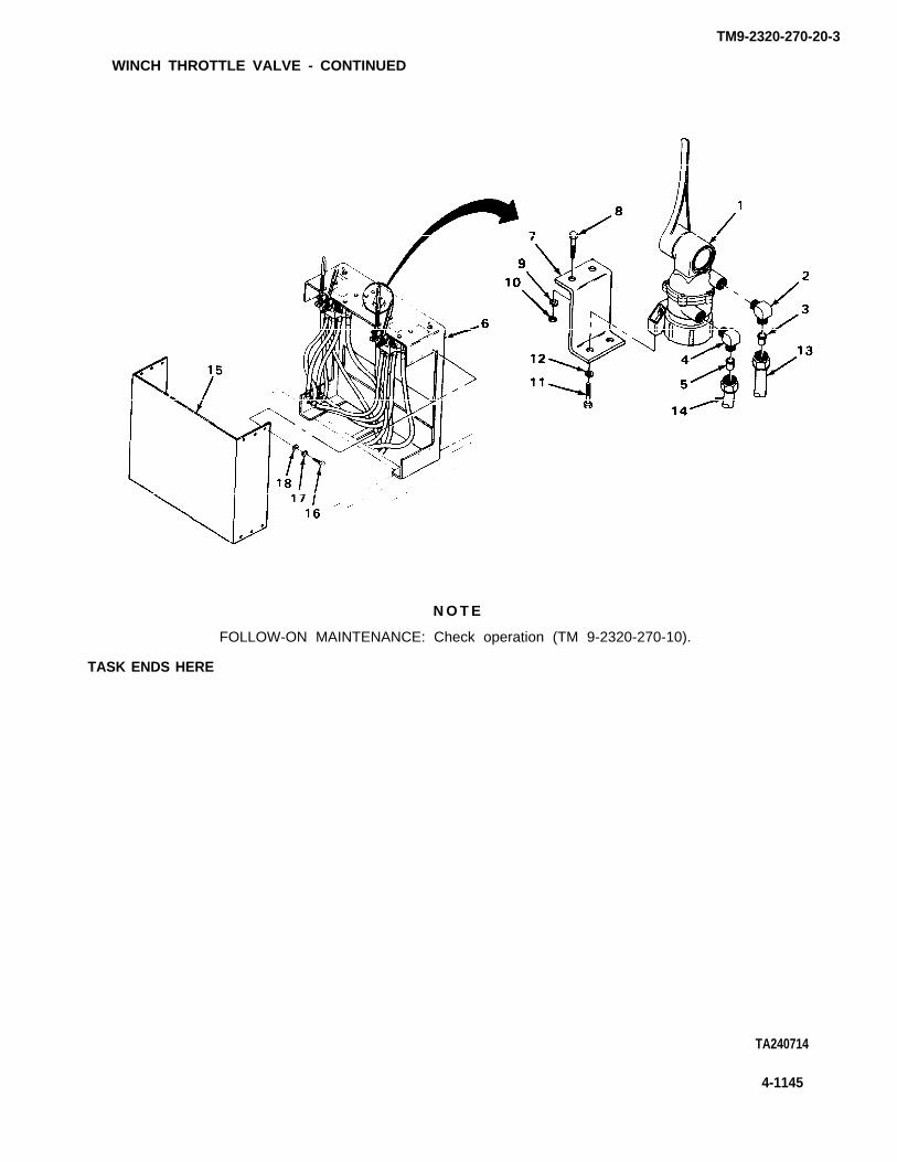
TM9-2320-270-20-3
WINCH THROTTLE VALVE - CONTINUED
N O T E
FOLLOW-ON MAINTENANCE: Check operation (TM 9-2320-270-10).
TASK ENDS HERE
TA240714
4-1145

TM9-2320-270-20-3
WINCH VALVES TO MOTORS HYDRAULIC LINES
This task covers:
a. Removal (page 4-1146)b. Installation (page 4-1148)
INITIAL SETUP
Tools Materials/Parts - Continued
Wrench, open-end, 7/16-inch Lockwashers, hose clamps (four required)(two required) Lockwashers, winch control panel
Wrench, open-end, 1/2-inch (12 required)Wrench, open-end, 5/8-inch Packing, preformed, hoseWrench, open-end, 1 1/2-inch Tag, marking (item 18, appendix C)Wrench, open-end, 2-inch
Personnel RequiredMaterials/Parts
OneHose plugsLockwashers, cover deck
(four required)
ACTIONLOCATION ITEM REMARKS
REMOVAL
N O T E
Tag hoses according to general maintenance instructions.
There are four sets of hoses. This procedure is for one set. Repeat for other three.
1. Winch control 12 screws (2), a. Using 1/2-inch wrench, unscrew andpanel (1) Iockwashers (3), take off.
and washers (4) b. Get rid of Iockwashers (3).
2. Front cover Take off.plate (5)
3. Cover deck (6) Four screws (7), a. Using two 7/16-inch wrenches, unscrewlockwashers (8), and take off.and nuts (9) b. Get rid of Iockwashers (8).
4. Rear winch and Cover deck (6) Lift off.tire carrierassembly (10)
4-1146

TM9-2320-270-20-3
WINCH VALVES TO MOTORS HYDRAULIC LINES - CONTINUED
LOCATIONACTION
ITEM REMARKS
5. Control valve (11) Hose (12) a. Using 1 1/2-inch wrench, unscrew andtake off.
b. Plug hose (12).
6. Tee (13) Hose (14) a. Using 2-inch wrench, unscrew and takeoff.
b. Plug hose (14).Repeat steps 5 and 6 for the otherhose.
TA240715
4-1147

TM9-2320-270-20-3
WINCH VALVES TO MOTORS HYDRAULIC LINES - CONTINUED
ACTION
LOCATION ITEM REMARKS
REMOVAL - CONTINUED
7. Tee (1) Hose (2) a.
b.
& Two hose clamps (3) Four screws (4), a.Iockwashers (5),hose (6) and b.packing (7)
c.
INSTALLATION
CAUTION
Do not overtighten hoses. Hoses or
9. Tee (1) Hose (2) a.b.
Using 2-inch wrench, unscrew and takeoff.Plug hose (12).
Using 5/8-inch wrench, unscrew andtake off.Get rid of Iockwashers (5) andpacking (7).Plug hose (6).
fittings will leak.
Take out plug.Using 2-inch wrench, screw on andtighten.
10. Hydraulic motor (8) New packing (7) Put in.
11. Hose (6) and two a. Take out plug.hose clamps (3) b. Put in place.
12. Two hose clamps (3) Four screws (4) Using 5/8-and new tighten.Iockwashers (5)
4-1148
inch wrench, screw in and
TA240716

TM9-2320-270-20-3
WINCH VALVES TO MOTORS HYDRAULIC LINES - CONTINUED
LOCATION ITEMACTION
REMARKS
13. Control valve (9) Hose (10) a. Take out plug.b. Using 1 1/2-inch wrench, screw on and
tighten.
14. T e e ( n )
15. Winch controlpanel (13)
16. Front coverplate (14)
17. Rear winch andtire carrierassembly (18)
18. Cover deck (19)
Hose (12)
Front coverplate (14)
12 screws (15), newIockwashers (16),and washers (17)
Cover deck (19)
Four screws (20),new Iockwashers(21), and nuts (22)
a. Take out plug.b. Using 2-inch wrench, screw on and
tighten.Repeat steps 13 and 14 for otherhose.
Put in place.
Using 1/2-inch wrench, screw in andtighten.
Place in position.
Screw in and tighten using two 7/16-inchwrenches.
TA240717
4-1149

WINCH VALVES TO MOTORS HYDRAULIC LINES - CONTINUED
INSTALLATION – CONTINUED
N O T E
FOLLOW-ON MAINTENANCE: Check operation (TM 9-2320-270-10).
TASK ENDS HERE
PUMP TO WINCH VALVES HYDRAULIC LINES
This task covers:
a. Removal (page 4-1150)b. Installation (page 4-1152)
INITIAL SETUP
Tools
Wrench, open-end, 5/8-inchWrench, open-end, 3/4-inchWrench, open-end, 2-inchWrench, open-end, 2 5/8-inchWrench, open-end, 2 7/8-inchWrench, pipe, 3-foot
Materials/Parts
Hose plugsLockwasher, hose clamp (eight required)Lockwashers, hose clamps (eight required)Packing, preformed, hoses (two required)Packing, preformed, hose (two required)Tag, marking (item 18, appendix C)
Personnel Required
One
ACTIONLOCATION ITEM REMARKS
REMOVAL
N O T E
Tag hoses according to general maintenance instructions (page 4-1).
1. Two pipes (1) Two unions (2) Using pipe wrench, unscrew part way.
2. Nipple (3) Hose (4) a. Using 2 7/8-inch wrench and 2 5/8 inchwrench, unscrew and take off.
b. Plug hose (4).
4-1150
TM9-2320-270-20-3

PUMP TO WINCH VALVES HYDRAULIC LINES - CONTINUED
ACTIONLOCATION ITEM REMARKS
3. Two hose clamps (5) Four screws (6), a. Using 3/4-inch wrench, unscrew andIockwashers (7), take off.hose (8), and b. Get rid of Iockwashers (7) andpacking (9) packing (9).
c. Plug hose (8).Repeat steps 2 and 3 for otherhose.
TA240718
4-1151
TM9-2320-270-20-3

TM9-2320-270-20-3
PUMP TO WINCH VALVES HYDRAULIC LINES - CONTINUED
.ACTION
LOCATION ITEM REMARKS
REMOVAL - CONTINUED
4. Hose clamps (1) Four screws (2), a.Iockwashers (3),hose (4), and b.packing (5)
c.
5. Elbow (6)
6. Nipple(8)
7. Nipple (10)
Hose (7) a.
Hose (9)
Hose(n)
b.
a.
b.
a.
b.
INSTALLATION
8. Nipple (10) Hose (11) a.b.
9. Nipple (8) Hose (9) a.b.
10. Elbow (6) Hose (7) a.b.
Using 5/8-inch wrench, unscrew andtake off.Get rid of Iockwashers (3) andpacking (5).Plug hose (4).
Using 2-inch wrench, unscrew and takeoff.Plug hose (7).
Repeat steps 4 and 5 for otherhose.
Using 2-inch wrench, unscrew and takeoff.Plug hose (9).
Using 2-inch wrench, unscrew and takeoff.Plug hose (11).
Repeat steps 6 and 7 for otherhose.
Take out plug.Using 2-inch wrench, screw in andtighten.
Take out plug.Using 2-inch wrench, screw in andtighten.
Repeat steps 8 and 9 for otherhose.
Take out plug.Using 2-inch wrench, screw in andtighten.
11. Hydraulic pump (12) New packing (5) Put in.
4-1152
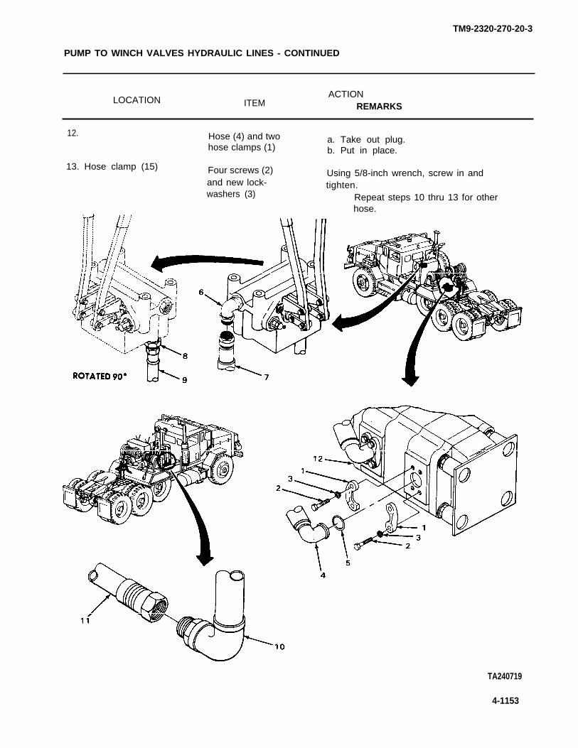
TM9-2320-270-20-3
PUMP TO WINCH VALVES HYDRAULIC LINES - CONTINUED
LOCATION ITEMACTION
REMARKS
12. Hose (4) and two a. Take out plug.hose clamps (1) b. Put in place.
13. Hose clamp (15) Four screws (2)and new lock-washers (3)
Using 5/8-inch wrench, screw in andtighten.
Repeat steps 10 thru 13 for otherhose.
TA240719
4-1153

TM9-2320-270-20-3
PUMP TO WINCH VALVES HYDRAULIC LINES - CONTINUED
ACTIONLOCATION ITEM REMARKS
INSTALLATION - CONTINUED
C A U T I O N
Do not overtighten hoses. Hoses or fittings will leak.
14. Nipple (1)
15. Pump (3)
16.
17. Hose clamps (6)
18. Two pipes (9)
Hose (2)
New packing (4)
Hose (5) andhose clamps (6)
Four screws (7) andnew Iockwashers (8)
Two unions (10)
TASK ENDS HERE
4-1154
a. Take out plug.b. Using 2 7/8-inch
tighten.
Put in.
a. Take out plug.b. Put in place.
wrench, screw on and
Using 3/4-inch wrench, screw in andtighten.
Repeat steps 14 thru 17 for otherhose.
a. Using pipe wrench, tighten.b. Check for leaks (page 4-1).
TA240720

WINCH HYDRAULIC VALVES
This task covers:
Adjustment (page 4-1155)
INITIAL SETUP
Tools Materials/Parts
Gage, multi-range pressure Lockwashers, winch control panelScrewdriver, flat-tip, 3/6-inch (12 required)Wrench, open-end, 1/2-inchWrench, open-end, 1 1/16-inch Personnel RequiredWrench, open-end, 2-inch
One
ACTIONLOCATION ITEM REMARKS
ADJUSTMENT
1. Winch control 12 screws (2), a. Using 1/2-inch wrench, unscrew andpanel (1) Iockwashers (3), take out.
and washers (4) b. Get rid of Iockwashers (3).
2. Front cover Take off.plate (5)
TA240721
4-1155
TM9-2320-270-20-3

TM9-2320-270-20-3
WINCH HYDRAULIC VALVES - CONTINUED
ACTIONLOCATION ITEM REMARKS
ADJUSTMENT - CONTINUED
3. Elbow (1) Inlet hose (2) a.
b.
Using 2-inch wrench, unscrew and takeoff.Install pressure gage between elbow
4. Valve (3)
5.
6.
(1) and hose (2).
Acorn nut (4) Using 1 1/16-inch wrench, unscrew andtake off.
Jamnut (5) Using 1 1/16-inch wrench, unscrew partway.
Pilot adjustment a.screw (6) b.
c.
7. Control valvearm (7)
8. Pilot adjustmentscrew (6)
9. Pilot adjustment Jamnut (5)screw (6)
10.
11. Elbow (1)
12. Winch controlpanel (8)
13. Front coverplate (9)
Acorn nut (4)
Inlet hose (2)
Using screwdriver, back off screw.Screw in until screw just seats.Start engine (TM 9-2320-270-10) andset at 1500 RPM.
Pull until pressure reading is noted ongage.
Using screwdriver, adjust until pressurereads 2050 ± 50 PSI at 39 GPM.
a.
b.
c.
Using screwdriver, and 11/16-inchwrench, tighten.Check gage and make sure reading iscorrect.Shut down engine(TM 9-2320-270-10).
Screw on and tighten using 11/16-inchwrench.
a. Remove pressure gage.b. Screw on and tighten using 2-inch
wrench.Repeat steps 3 thru 11 for othervalve.
Front cover Put in place.plate (9)
12 screws (10), Screw in and tighten using 1/2-inchwashers (11), and wrench.new Iockwashers (12)
4-1156

WINCH HYDRAULIC VALVES - CONTINUED
N O T E
FOLLOW-ON MAINTENANCE: Check
TASK ENDS HERE
WINCH CONTROL VALVE
for leaks (TM 9-2320-270-10),
This task covers:
a. Removal (page 4-1158) c. Inspection/Replacement (page 4-1158).b. Cleaning (page 4-1158) d. Installation (page 4-1158)
INITIAL SETUP
Tools Materials/Parts - Continued
Handle, ratchet, 1/2-inch drive Lockwashers, winch control paneI (12Socket, 1/2-inch drive, 3/4-inch required)Wrench, adjustable, 0 to 3 5/8-inch Tag, marking (item 18, appendix C)Wrench, open-end, 1/2-inch Tape, teflon (item 22, appendix C)Wrench, open-end, 3/4-inch
Materials/Parts
Hose plugsLockwashers,
required)
Personnel Required
One
winch control panel (four
TA240722
4-1157
TM9-2320-270-20-3

TM9-2320-270-20-3
WINCH CONTROL VALVE - CONTINUED
ACTIONLOCATION ITEM REMARKS
REMOVAL
N O T E
Tag lines according to general maintenance instructions (page 4-1).
1. Winch control 12 screws (2), a. Using 1/2-inch wrench, unscrew andpanel (1) Iockwashers (3), take out.
and washers (4) b. Get rid of Iockwashers (3).
2. Front cover Take off.plate (5)
3. Control valve (6) Four hoses a. Using adjustable wrench, unscrew and(7), (8), (9), take off.and (10) b. Plug.
4.
5. Winch controlpanel (1)
6.
CLEANING
7.
INSPECTION/REPLACEMENT
8.
INSTALLATION
9. Winch controlpanel (1)
10. Control valve (6)
Two hoses (11) a. Using 0 to 3 5/8-inch automobile ad-and (12) justable wrench, unscrew and take off.
b. Plug.
Four screws (13), a. Using 3/4-inch wrench, 3/4-inch sock-Iockwashers (14), et and ratchet handle with 1/2-inchand nuts (15) drive, unscrew and take out.
b. Get rid of Iockwashers (14).
Control valve (6) Take off.
All parts
All parts
Clean according to general maintenanceinstructions (page 4-1).
Inspect according to general maintenanceinstructions (page 4-1).
Control valve (6) Place in position.
Four screws (13), Screw in and tighten, using 3/4-inchnew Iockwashers socket, ratchet handle with 1/2-inch(14), and nuts (15) drive and 3/4-inch wrench.
4 - 1 1 5 8

TM9-2320-270-20-3
WINCH CONTROL VALVE - CONTINUED
ACTIONLOCATION ITEM REMARKS
11. Four hoses (7), (8), a. Unplug.(9), and (10) b. Wrap threads with teflon tape
(page 4-1).c. Screw on and tighten using adjustable
wrench.
a. Unplug.b. Wrap threads with teflon tape
(page 4-1).c. Screw on and tighten using adjustable
wrench.
13. Winch control Front cover Place in position.panel (1) plate (5)
14. Front cover 12 screws (2), new Screw in and tighten using 1/2-inchplate (5) Iockwashers (3), wrench.
and washers (4)
12. Two hoses(11) and (12)
TA240723
4-1159

WINCH CONTROL VALVE - CONTINUED
INSTALLATION - CONTINUED
N O T E
FOLLOW-ON MAINTENANCE: Check for leaks (page 4-1).
TASK ENDS HERE
HYDRAULIC RESERVOIR DRAINING AND FILLING
This task covers:
a. Draining (page 4-1160)b. Filling (page 4-1162)
INITIAL SETUP
Tools
Barrels, steel, 55-gallon (tworequired)
Knife, puttyPan, drainPump, rotary handWrench, open-end, 1/2-inchWrench, open-end, 5/8-inchWrench, open-end, 2-inchWrench, pipe
Materials/Parts
Cement, gasket (item 2, appendix C)Gasket, filter assemblyLockwashers (four required)
Personnel Required
One
Equipment Condition
Spare tire removed (TM 9-2320-270-10).
ACTIONLOCATION ITEM REMARKS
DRAINING
1. Pipe (1)
2. Cover (3)
3. Reservoir (6)
Union (2) Using pipe wrench, unscrew and slide backalong pipe.
Four screws (4) and a. Using 1/2-inch wrench, unscrew andIockwashers (5) take out.
b. Get rid of Iockwashers (5).
Cover (3) and Lift out.filter (7)
TM9-2320-270-20-3
4-1160

TM9-2320-270-20-3
HYDRAULIC RESERVOIR DRAINING AND FILLING - CONTINUED
ACTIONLOCATION ITEM REMARKS
4. Cover (3) Filter (7) Using 2-inch wrench, unscrew and takeoff.
5. Gasket (8) a.b.
6. Reservoir (6) Drainplug (9) a.
b.c.
d.e.
Using putty knife, scrape off.Get rid of.
Using rotary pump and barrels, pumpout hydraulic fluid.Place drain pan underneath.Using 5/8-inch and take out.Allow remainingIf fluid is contamof it (page 4-1).
wench, unscrew and
fluid to drain.inated, get rid
TA240724
4-1161

TM9-2320-270-20-3
HYDRAULIC RESERVOIR DRAINING AND FILLING - CONTINUED
ACTION
LOCATION ITEM REMARKS
FILLING
7. Reservoir (1) Drainplug (2) a.
b.
8. Cover (3) New gasket (4) a.b.
Screw in plug and tighten using 5/8-inch wrench.Using rotary pump, fill.
Apply gasket cement to cover (3).Place in position.
9. Filter (5) Screw on and tighten using 2-inch wrench.
10. Reservoir (1) Cover (3) Put in position.
11. Cover (3) Four screws (6) Screw in and tighten using 1/2-inchand new lock- wrench.washers (7)
12. Pipe (8) Union (9) Screw on and tighten using pipe wrench.
N O T E
FOLLOW-ON MAINTENANCE:
1. Install spare tire (TM 9-2320-270-10).2. Check for leaks (page 4-1).
TASK ENDS HERE
TA240725
4-1162

This task covers:
a. Removal (page 4-1164)b. Installation (page 4-1168)
INITIAL SETUP
Tools Materials/Parts
Hammer, plasticHandle, ratchet, 3/8-inch driveHandle, ratchet, 1/2-inch driveKnife, pocketKnife, puttyLifting equipmentPliers, diagonal-cuttingScrewdriver, flat-tip, 5/16-inchSocket, 1/2-inch, 1/2-inch driveSocket, 15/16-inch, 1/2-inch driveSocket handle, 1/2-inch driveVise, machinist’sWrench, adjustable, 0 to 3 5/8-inch
(two required)Wrench, open-end, 1/2-inchWrench, open-end, 5/8-inchWrench, open-end, 9/16-inchWrench, open-end, 15/16-inch
(two required)Wrench, open-end, 1 1/16-inchWrench, pipe (two required)
Cotter pinGaskets (three required)Lockwashers, U-bolts (eight required)Nipple, reservoirPacking, preformed, filter baseSeal, washer,Tape, teflon (item 22, appendix C)Wrap, tie (item 24, appendix C)
Personnel Required
One
Equipment Condition
Spare tire removed (TM 9-2320-270-10).Spare tire mount removed (page 4-1055).Hydraulic reservoir drained (page 4-1160).Hydraulic oil filter removed (page 4-1172).
4-1163
TM9-2320-270-20-3

TM9-2320-270-20-3
HYDRAULIC RESERVOIR -CONTINUED
ACTIONLOCATION ITEM REMARKS
REMOVAL
1.
2.
3.
4.
5.
6.
7.
8.
9.
10.
Nipple (1)
Two U-bolts (3)and (4)
Two U-bolt brackets(8) and (9)
Elbow (1 O)
Pipe(n)
U-bolt bracket (9)
Elbow (13)
Reducer bushing (15)
Tee pipe (16)
Reservoir (17)
Hose (2)
Four nuts (5),washers (6) andIockwashers (7)
Two U-bolts (3)and (4)
Pipe(n)
Tie wraps (12)
Pipe(n)
Hose (14)
Elbow (13)
Reducer bushing (15)
Tee pipe (16)
a.
b.
a.
b.
Using two adjustable wrenches,unscrew and take off.Plug.
Repeat step 1 for other hose.
Using 1/2-inch wrench, unscrew andtake off.Get rid of Iockwashers (7).
Take off.Repeat steps 2 and 3 for otherU-bolts.
Using pipe wrench, unscrew and takeRepeat step 4 for other pipe.
a. Using pliers, take off.b. Get rid of.
Move out of way.
off.
Repeat steps 5 and 6 for other pipe.
Using 9/16-inch wrench, unscrew and takeoff.
Using 5/8-inch and 1 1/16-inch open-endwrenches, unscrew and take off.
Using 1 1/16-inch open-end wrench andpipe wrench, unscrew and take off.
Using pipe wrench, unscrew and take off.
N O T E
Do not remove nipple unless it is damaged and needs replacement.
If nipple stays in tee pipe and must be removed, do step 11. If nipple stays in reservoirand must be removed, do step 12.
11. Tee pipe (16) Nipple (18) a. Secure tee pipe (16) in vise.b. Using pipe wrench, unscrew and take
out.c. Get rid of.d. Take tee pipe (16) out of vise.
4-1164

TM9-2320-270-20-3
HYDRAULIC RESERVOIR - CONTINUED
ACTION
LOCATION ITEM REMARKS
12. Reservoir (17) Nipple (18) a. Using pipe wrench, unscrew and takeout.
b. Get rid of.
TA240726
4-1165
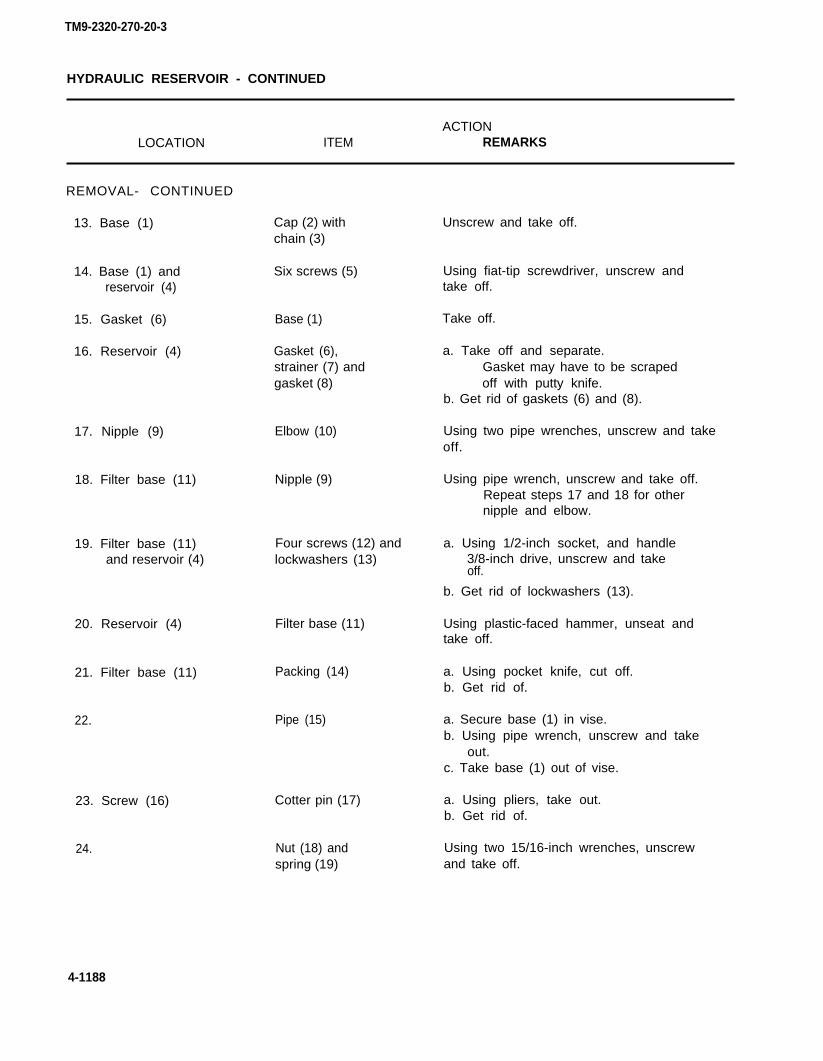
HYDRAULIC RESERVOIR - CONTINUED
ACTIONLOCATION ITEM REMARKS
REMOVAL- CONTINUED
13. Base (1) Cap (2) withchain (3)
14. Base (1) and Six screws (5)reservoir (4)
15. Gasket (6) Base (1)
16. Reservoir (4) Gasket (6),strainer (7) andgasket (8)
17. Nipple (9)
18. Filter base (11)
19. Filter base (11)and reservoir (4)
20. Reservoir (4)
21. Filter base (11)
22.
23. Screw (16)
24.
Elbow (10)
Nipple (9)
Four screws (12) andlockwashers (13)
Filter base (11)
Packing (14)
Pipe (15)
Cotter pin (17)
Nut (18) andspring (19)
Unscrew and take off.
Using fiat-tip screwdriver, unscrew andtake off.
Take off.
a. Take off and separate.Gasket may have to be scrapedoff with putty knife.
b. Get rid of gaskets (6) and (8).
Using two pipe wrenches, unscrew and takeoff.
Using pipe wrench, unscrew and take off.Repeat steps 17 and 18 for othernipple and elbow.
a. Using 1/2-inch socket, and handle3/8-inch drive, unscrew and takeoff.
b. Get rid of lockwashers (13).
Using plastic-faced hammer, unseat andtake off.
a. Using pocket knife, cut off.b. Get rid of.
a. Secure base (1) in vise.b. Using pipe wrench, unscrew and take
out.c. Take base (1) out of vise.
a. Using pliers, take out.b. Get rid of.
Using two 15/16-inch wrenches, unscrewand take off.
4-1188
TM9-2320-270-20-3

TM9-2320-270-20-3
HYDRAULIC RESERVOIR - CONTINUED
ACTIONLOCATION ITEM REMARKS
25. Reservoir (4) Two screws (20) Using 15/16-inch wrench, unscrew andtake off.
Some parts are heavy. Be careful when handling them. Lifting equipment is neededwhen parts weigh over 50 pounds (23 kg) for a single person lift, over 100 pounds(45 kg) for a two person lift, and over 150 pounds (68 kg) for a three or more personlift. Do not try to handle heavy parts without lifting equipment. Keep clear of heavy partssupported only by lifting equipment. Failure to observe this precaution could causeserious injury or death of personnel.
26. Deck (21) Reservoir (4) and a. Attach lifting equipment.three spacers (22) b. Using lifting equipment, take out.
c. Take out spacers (22).
4-1167
W A R N I N G
TA240727

TM9-2320-270-20-3
HYDRAULIC RESERVOIR - CONTINUED
ACTIONLOCATION ITEM REMARKS
REMOVAL - CONTINUED
27. Reservoir (1) andcover (2)
28. Reservoir (1)
INSTALLATION
29.
30.
31. Reservoir (1)and cover (2)
Screw (3) and sealwasher (4)
Cover (2) andgasket (5)
New gasket (5)
Cover (2)
New seal washer (4)and screw (3)
a. Using 15/16-inch socket and handlewith 1/2-inch drive, unscrew and takeoff.
b. Get rid of seal washer (4).
a. Take off.b. Get rid of gasket (5).
Put in place.
Put in place.
Screw in and tighten using 15/16-inchsocket and handle with 1/2-inch drive.
W A R N I N G
Some parts are heavy. Be careful when handling them. Lifting equipment is neededwhen parts weigh over 50 pounds (23 kg) for a single person lift, over 100 pounds(45 kg) for a two person lift, and over 150 pounds (68 kg) for a three or more personlift. Do not try to handle heavy parts without lifting equipment. Keep clear of heavy partssupported only by lifting equipment. Failure to observe this precaution could causeserious injury or death of personnel.
32. Deck (6) Three spacers (7) a. Put spacers (7) in place.and reservoir (1) b. Attach lifting equipment.
c. Using lifting equipment, place inposition.
33. Reservoir (1)
34.
35.
38. Filter base (13)
37.
Two screws (8) Screw in and tighten using 15/16-inchwrench.
Screw (9), spring Screw on and tighten using two 15/16-inch(10) and nut (11) wrenches.
New cotter pin (12) Using pliers, put on.
Pipe (14) a. Put filter base (13) in vise.b. Screw in and tighten using pipe wrench.c. Take filter base (13) out of vise.
New packing (15) Put in place.
4-1168

TM9-2320-270-20-3
HYDRAULIC RESERVOIR - CONTINUED
LOCATION ITEMACTION
REMARKS
36. Reservoir (1) Filter base (13) Put in place.
39. Filter base (13)and reservoir (1)
40. Filter base (13)
41. Nipple (18)
Four new Iockwashers Screw in and tighten using 1/2-inch socket(16) and screws (17) and
N O T E
Wrap ail external threads with teflon
Nipple (18)
Elbow (19)
handle 1/2-inch drive. -
tape (page 4-1).
Screw in and tighten using pipe wrench.
Screw in and tighten using two pipewrenches.
Repeat steps 39 and 40 for othernipple and elbow.
4-1169
TA240728

TM9-2320-270-20-3
HYDRAULIC RESERVOIR - CONTINUED
ACTIONLOCATION ITEM REMARKS
INSTALLATION – CONTINUED
42.
43.
44.
45.
46.
47.
48.
49.
50.
51.
52.
53.
54.
55.
Reservoir (1)
New gasket (4)
Base (5) andreservoir (1)
Base (5)
Tee pipe (9)
Reservoir (1)
Tee pipe (9)
Reducer bushing (11)
Eibow (12)
U-bolt bracket (14)
Pipe (15)
Hose (13) andpipe (15)
Elbow (17)
U-bolt bracket (19)and (14)
New gasket (2),strainer (3) andnew gasket (4)
Base (5)
Six screws (6)
Cap (7) withchain (8)
New nipple (10)
Tee pipe (9) withnew nipple (10)
Reducer bushing (11)
Elbow (12)
Hose (13)
Pipe (15)
Hose (13)
New tie wraps (16)
Pipe (18)
Two U-bolts (20)
Put in place.
Put in place.
Screw in and tighten using flat-tipscrewdriver.
Screw on and tighten.
Screw in.
Screw in and tighten using pipe wrench.
Screw in and tighten using 1 1/16-inchopen-end wrench and pipe wrench.
Screw in and tighten using 5/8-inch and1 1/16-inch open-end wrenches.
Screw in and tighten using 9/16-inchwrench.
Put in place.Repeat step 54 for other pipe.
Put hose (13) next to pipe (15).
Using pliers, put on.
Screw in and tighten using pipe wrench.Repeat step 54 for other pipe.
Put in place.
4-1170

HYDRAULIC RESERVOIR -CONTINUED
ACTIONLOCATION ITEM REMARKS
56. Two U-bolts (20) Four new Iockwashers Screw in and tighten using 1/2-inch
57. Nipple (24)
(21), washers (22)and nuts (23)
Hose (25)
wrench.
a.b.
Repeat steps 55 and 58 for otherUnbolts.
Unplug.Screw in and tighten using two 2-inchopen-end wrenches.
TA240729
4-1171
TM9-2320-270-20-3

TM9-2320-270-20-3
HYDRAULIC RESERVOIR -CONTINUED
INSTALLATION – CONTINUED
N O T E
FOLLOW-ON MAINTENANCE:
1. Install hydraulic oil filters (page 4-1172).2. Fill hydraulic reservoir (page 4-1160).3. Install spare tire mount (page 4-1055.4. Install spare tire (TM 9-2320-270-10).
TASK ENDS HERE
HYDRAULIC OIL FILTER
This task covers:
a. Removal (page 4-1172)b. Installation (page 4-1174)
INITIAL SETUP
Tools Materials/Parts – Continued
Knife, putty Adhesive, sealant (item 1, appendix C)Wrench, adjustable, 0 to 3 5/8-inch Fluid, hydraulic (LO 9-2320-270-12)Wrench, filter Lockwashers (four required)Wrench, open-end, 1/2-inch Rags, wiping (item 10, appendix C)Wrench, pipe
Materials/Parts Personnel Required
Gasket One
ACTIONLOCATION ITEM REMARKS
REMOVAL
N O T E
There are two hydraulic oil filters. This procedure covers one. Repeat as necessary forother.
1. Filter base (1) Oil filter (2) a. Using filter wrench, unscrew and takeoff.
b. Using rags, clean up any spills.
4-1172

TM9-2320-270-20-3
HYDRAULIC OIL FILTER - CONTINUED
ACTIONLOCATION ITEM REMARKS
2. Plate (3) Four screws (4) andIockwashers (5)
3. Pipe (6) Union (7)
4. Reservoir (8) Filter screenassembly (9) andgasket (10)
5. Plate (3)
6. Filter screenassembly (9)
Gasket (10)
Filter screennut (11)
a. Using 1/2-inch wrench, unscrew andtake out.
b. Get rid of Iockwashers (5).
Using pipe wrench, unscrew and slide backalong pipe.
a. Take out.b. Using rags, clean up any spills.
Using putty knife, scrape off.
Using adjustable wrench, unscrew andtake off.
TA240730
4-1173

HYDRAULIC OIL FILTER - CONTINUED
ACTIONLOCATION ITEM REMARKS
INSTALLATION
7. Oil filter (1)
8. Filter base (3)
9. Plate (4)
10. Filter screenassembly (6)
11. Reservoir (8)
12 Plate (4)
13. Pipe (11)
.
Gasket ring (2)
Oil filter (1)
New gasket (5)
Filter screennut (7)
Plate (4)
Four screws (9) andnew Iockwashers (10)
Union (12)
Apply thin coat of hydraulic oil.
Screw in.Do not overtighten.
Put on.
Using adjustable wrench, screw on andtighten.
a. Apply sealant around hole in reservoirand in each screw hole.
b. Place in position.
Using 1/2-inch wrench, screw in andtighten.
Using pipe wrench, screw on and tighten.
TASK ENDS
4-1174
N O T E
FOLLOW-ON MAINTENANCE: Check for leaks (TM 9-2320-270-10).
HERE
TA240731
TM9-2320-270-20-3

WINCH PROPELLER SHAFT
This task covers:
a. Removal (page 4-1175)b. Installation (page 4-1176)
INITIAL SETUP
Tools Personnel Required
Bar, pry OneHammer, machinist’s, ball-peenKey, socket-head screw, 3/16-inch Equipment ConditionPunch, drive pin, 5/32-inch
Spare tire removed (TM 9-2320-270-10).
ACTIONLOCATION ITEM REMARKS
REMOVAL
1. Two yokes (1)
2. Two shafts (3)
3. Two keyways (4)
Two screws (2)
Two yokes (1)
Two keys (5)
Using 3/16-inch key, unscrew.
a. Using hammer, tap to break loose.b. Using pry bar, take off.
Using hammer and 5/32-inch punch, driveout.
TA240732
4-1175
TM9-2320-270-20-3

WINCH PROPELLER SHAFT - CONTINUED
ACTIONLOCATION ITEM REMARKS
INSTALLATION
4. Two keyways (1)
5. Two shafts (3)
6. Two yokes (4)
Two keys (2)
Two yokes (4)
Two screws (5)
Using hammer, tap in.
Line up keys (2) and keyways and put on.
Using 3/16-inch key, screw in andtighten.
N O T E
FOLLOW-ON MAINTENANCE: Install spare tire (TM 9-2320-270-10).
TASK ENDS HERE
TA240733
4-1176
TM9-2320-270-20-3

TM9-2320-270-20-3
Section XVIII. ACCESSORIES MAINTENANCE
Air Horn . . . . . . . . . . . . . . . . . . . . . . . . . . . . . . . . . . . . . . . . . . . . . . . . . . . . . . . . .Air Horn Air Lines . . . . . . . . . . . . . . . . . . . . . . . . . . . . . . . . . . . . . . . . .Air Horn Chain . . . . . . . . . . . . . . . . . . . . . . . . . . . . . . . . . . . . . . . . . . . . . .Air Horn Valve . . . . . . . . . . . . . . . . . . . . . . . . . . . . . . . . . . . . . . . . . . . . . . .Convex Mirror Head . . . . . . . . . . . . . . . . . . . . . . . . . . . . . . . . . . . . . .Data Plates and Decals Secured
With Adhesive . . . . . . . . . . . . . . . . . . . . . . . . . . . . . . . . . . . . . . . . . . .Data Plates Secured With Blind
Rivets . . . . . . . . . . . . . . . . . . . . . . . . . . . . . . . . . . . . . . . . . . . . . . . . . . . . . . . . .Data Plates Secured With
Drivescrews . . . . . . . . . . . . . . . . . . . . . . . . . . . . . . . . . . . . . . . . . . . . . .Data Plates Secured With
Self-Tapping Screws . . . . . . . . . . . . . . . . . . . . . . . . . . . . . . . .Defroster Hose . . . . . . . . . . . . . . . . . . . . . . . . . . . . . . . . . . . . . . . . . . . . . .Defroster Knob and Cable . . . . . . . . . . . . . . . . . . . . . . . . . . .Defroster Nozzle . . . . . . . . . . . . . . . . . . . . . . . . . . . . . . . . . . . . . . . . . . .Engine Data Plate . . . . . . . . . . . . . . . . . . . . . . . . . . . . . . . . . . . . . . . . .Heater Assembly . . . . . . . . . . . . . . . . . . . . . . . . . . . . . . . . . . . . . . . . . .Heater Control Panel . . . . . . . . . . . . . . . . . . . . . . . . . . . . . . . . . . . .Heater Control Panel Bezels . . . . . . . . . . . . . . . . . . . . . . . .Heater Control Panel Optical
Ribbon . . . . . . . . . . . . . . . . . . . . . . . . . . . . . . . . . . . . . . . . . . . . . . . . . . . . . . .Heater Coolant Return Elbow . . . . . . . . . . . . . . . . . . . . . .Heater Core . . . . . . . . . . . . . . . . . . . . . . . . . . . . . . . . . . . . . . . . . . . . . . . . . . .Heater Deflector . . . . . . . . . . . . . . . . . . . . . . . . . . . . . . . . . . . . . . . . . . .Heater Hoses . . . . . . . . . . . . . . . . . . . . . . . . . . . . . . . . . . . . . . . . . . . . . . . .
WINDSHIELD WASHER JET ASSEMBLY
Page
4-12514-12604-12494-12444-1228
4-1224
4-1322
4-1325
4-13274-12904-12724-12894-13294-12754-13074-1312
4-13124-13194-12654-12884-1293
Heater Knob and Cable . . . . . . . . . . . . . . . . . . . . . . . . . . . . . .Heater Motor . . . . . . . . . . . . . . . . . . . . . . . . . . . . . . . . . . . . . . . . . . . . . . .Heater Motor Suppressor . . . . . . . . . . . . . . . . . . . . . . . . . .Heater Resistor . . . . . . . . . . . . . . . . . . . . . . . . . . . . . . . . . . . . . . . . . . .Heater Shutoff Valve . . . . . . . . . . . . . . . . . . . . . . . . . . . . . . . . . .Heater Switch . . . . . . . . . . . . . . . . . . . . . . . . . . . . . . . . . . . . . . . . . . . . .Instrument Panel Illuminated Label
Assembly . . . . . . . . . . . . . . . . . . . . . . . . . . . . . . . . . . . . . . . . . . . . . . . .Instrument Panel Non-illuminated
Label Assembly . . . . . . . . . . . . . . . . . . . . . . . . . . . . . . . . . . . . . .Mirror Detent Loop Assembly . . . . . . . . . . . . . . . . . . . .Mirror Mounting Tube Assembly . . . . . . . . . . . . . . .Rear View Mirror Head . . . . . . . . . . . . . . . . . . . . . . . . . . . . . . .Spotter Mirror Head and BracketWindshield Washer Control Valve . . . . . . . . . . . .Windshield Washer Jet Assembly . . . . . . . . . . . .Windshield Washer Nylon Air
Line . . . . . . . . . . . . . . . . . . . . . . . . . . . . . . . . . . . . . . . . . . . . . . . . . . . . . . . . . .Windshield Washer Reservoir . . . . . . . . . . . . . . . . . . .Windshield Washer Rubber Hose . . . . . . . . . . . . .Windshield Wiper Motor . . . . . . . . . . . . . . . . . . . . . . . . . . . .Wiper Air Lines . . . . . . . . . . . . . . . . . . . . . . . . . . . . . . . . . . . . . . . . . . .Wiper Arm and Blade . . . . . . . . . . . . . . . . . . . . . . . . . . . . . . . . .Wiper Control Valve . . . . . . . . . . . . . . . . . . . . . . . . . . . . . . . . . . . .Wiper Vent Lines . . . . . . . . . . . . . . . . . . . . . . . . . . . . . . . . . . . . . . . .
Page
4-12844-12704-13164-13154-13024-1312
4-1330
4-13304-12294-12324-12264-12424-11824-1177
4-11854-11804-11864-11914-12084-12054-12004-1220
This task covers:
a. Removal (page 4-1178) c. Installation/Adjustment (page 4-1178)b. Cleaning/Inspection (page 4-1178)
INITIAL SETUP
Tools Materials/Parts – Continued
Knife, pocket Wire, non-electrical (item 23, appendix C)Wrench, open-end, 9/32-inchWrench, open-end, 7/16-inch Personnel RequiredWrench, open-end, 5/8-inch
Two
Materials/Parts Equipment Condition
Gasket, windshield washer jet to cowl Instrument panel open (page 4-244).Solvent, cleaning (item 16, appendix C)
4-1177

TM9-2320-270-20-3
WINDSHIELD WASHER JET ASSEMBLY - CONTINUED
ACTIONLOCATION ITEM REMARKS
REMOVAL
N O T E
Except as noted, steps in this task are the same for both right and left windshield washerjet assemblies. Right jet assembly is shown.
1. Jet fitting (1) Jet (2) Using 9/32-inch wrench, unscrewtake out.
2. Hose (3) Pull off.If hose is brittle, replace it(page 4-1).
and
3. Jet fitting (1) Nut (5) With help from assistant and using 7/16-to cowl (4) inch and 5/8-inch wrenches, unscrew and
take off.
4. Cowl (4) Jet fitting (1) Turn and take out.
5. Jet fitting (1) Gasket (6) a. Take off.b. Get rid of.
CLEANING/INSPECTiONW A R N I N G
Drycleaning solvent P-D-680 is toxic and flammable. Wear protective goggles andgloves and use only in a well ventilated area. Avoid contact with skin, eyes, and clothesand don’t breathe vapors. Do not use near open frame or excessive heat. The flashpointis 100°F to 138°F (38° to 59°C). if you become dizzy while using cleaning solvent, getfresh air immediately and get medical aid. if contact with eyes is made, wash your eyeswith water and get medical aid immediately.
6. Jet (2) and jet a. Soak in solvent for at least 30 minutes.fitting (1) b. Using wire, clean out passges.
If passages are still plugged,replace jet assembly.
c. Look for stripped threads and otherdamage.
Replace if damaged.
INSTALLATION/ADJUSTMENT
7. Jet fitting (1)
8. Cowl (4)
New gasket (6)
Jet fitting (1)
Put on.
Turn and put in place.
4-1178

TM 9-2320-270-20-3
WINDSHIELD WASHER JET ASSEMBLY - CONTINUED
ACTIONLOCATION ITEM REMARKS
9. Jet fitting (1) Nut (5)to cowl (4)
10. Jet fitting (1)
11.
12.
13.
14. Cowl (4)
Hose (3)
Jet (2)
Air system
Windshield washercontrol (7)
Jet fitting (1)
1. Jet fitting (1)
16.
Jet (2)
instrument panel
a.
b.
With help from assistant and using5/8-inch wrench, position so jet (2)will face toward outside.Screw on.
Push on.
Have assistant screw in.
Pressurize (TM 9-2320-270-10).
Step on control and watch spray pattern.
a. Have assistant, using 5/8-inchwrench, turn so fluid is sprayed intocenter of windshield wiper pathright to left.
b. Using 7/16-inch wrench, tightennut (5).
Have assistant, using 9/32-inch wrench,tighten until fluid is sprayed intocenter of windshield wiper path up anddown.
Close (page 4-244).
TASK ENDS HERETA240734
4-1179

WINDSHIELD WASHER RESERVOIR
This task covers:
a. Removal (page 4-1180) c. Assembly (page 4-1181)b. Disassembly (page 4-1180) d. Installation (page 4-1181)
—
INITIAL SETUP
Tools Personnel Required
Handle, ratchet head, 3/8-inch drive TwoScrewdriver, cross-tip, offset,
number 1 Equipment ConditionSocket, 3/8-inch, 3/8-inch drive
Left side of hood opened (TM 9-2320-270-10).Materials/Parts
Lockwasher, reservoir to firewall(two required)
Tag, marking (item 18, appendix C)
ACTIONLOCATION ITEM REMARKS
REMOVAL
NOTE
Tag hoses according to general maintenance instructions (page 4-1).
1. Reservoir (1) and Two hoses Pull off.cover (2) (3) and (4)
2. Bracket (5) Reservoir (1) Lift out.
3. Bracket (5) to Three screws (7), a.firewall (6) nuts (8), lock-
washers (9), andbracket (5) b.
DISASSEMBLY
With help from assistant and usingscrewdriver, 3/8-inch socket andhandle, unscrew and take out.Get rid of Iockwashers (9).
4. Reservoir (1) Cap (10) Unscrew and take off.
5. Cover and pump a. Take out.assembly (2) b. Get rid of fluid (page 4-1).
4-1180
TM 9-2320-270-20-3

TM 9-2320-270-20-3
ACTIONLOCATION ITEM REMARKS
ASSEMBLY
6. Reservoir (1)
7.
INSTALLATION
8. Firewall (6)
9. Bracket (5) tofirewall (6)
10. Bracket (5)
11. Cover (2)
12.
13.
Cover and pumpassembly (2)
Cap (10)
Bracket (5)
Three screws (7),new Iockwashers (9),and nuts (8)
Reservoir (1)
Fluid hose (4)
Air hose (3)
Reservoir (1)
Put in.
Screw on and tighten.
Place in position.
With help from assistant, screw in andtighten using screwdriver, 3/8-inchsocket and handle.
Put in.
Push onto nipple marked W.
Push onto nipple marked A.
Fill (TM 9-2320-270-10).
TA240735
4-1181
WINDSHIELD WASHER RESERVOIR - CONTINUED

TM 9-2320-270-20-3
WINDSHIELD WASHER RESERVOIR - CONTINUED
NOTE
FOLLOW-ON MAINTENANCE:
1. Close left side of hood (TM 9-2320-270-10).2. Check operation (TM 9-2320-270-10).
TASK ENDS HERE
WINDSHIELD WASHER CONTROL VALVE
This task covers:
a. Removal (page 4-1182) d. inspection/Replacement (page 4-1 184)b. Disassembly (page 4-1184) e. Assembly (page 4-1184)c. Cleaning (page 4-1184) f. installation (page 4-1184)
INITIAL SETUP
Tools
Extension, 5-inch, 3/8-inch driveHammer, plasticHandle, ratchet, 3/8-inch drivePliers, long-nose, roundPliers, slip-joint, straight-noseSocket, 7/16-inch, 3/8-inch driveViseWrench, box, 7/16-inchWrench, open-end, 7/16-inchWrench, open-end, 9/16-inch
Materials/Parts
Lockwasher, windshield washer controlvalve to firewall (two required)
Materials/Parts – Continued
Soap, liquid (item 14, appendix C)Tape, teflon (item 22, appendix C)
Personnel Required
Two
Equipment Condition
Left side of hood opened(TM 9-2320-270-10).
ACTIONLOCATION iTEM REMARKS
REMOVAL
WARNING
Make sure all pressure is drained from air system before disconnecting air lines. Partsunder pressure can, when removed, fly off with great force causing injury to personnel.
4-1182

TM 9-2320-270-20-3
WINDSHIELD WASHER CONTROL VALVE - CONTINUED
ACTIONLOCATION ITEM REMARKS
1. Air system Drain (TM 9-2320-270-10).
2. Elbow (1) Airline(2) Using 9/16-inch wrench, unscrew and pullout.
3. Air line (2) Insert (3) Using long-nose pliers, pull out.or elbow (1)
4. Hose (4) to Clamp (6) Using pliers, open and slide back.adapter (5)
5. Adapter(5)
6. Valve (7) tofirewall (8)
7. Firewall (8)
Hose (4)
Two screws (9),washers (10),nuts (11), andIockwashers (12)
Valve (7)
Pull off.
a. With help from assistant and using7/16-inch box wrench, 7/16-inchsocket, extension, and handle, unscrewand take off.
b. Get ridofIockwashers(11).
Take out.
TA240736
4-1183

TM 9-2320-270-20-3
WINDSHIELD WASHER CONTROL VALVE - CONTINUED
ACTIONLOCATION ITEM REMARKS
DISASSEMBLY
8. Valve (1)
9.
CLEANING
10.
lNSPECTION/REPLACEMENT
11.
ASSEMBLY
12. Valve (1)
13.
INSTALLATION
14. Firewall (4)
15. Valve (1) tofirewall (4)
16. Adapter (3)
17. Hose (9) toadapter (3)
Elbow (2) a. Secure valve (1) in vise.b. Using 7/16-inch open-end wrench,
unscrew and take out.
Adapter (3) a. Using 7/16-inch box wrench, unscrewand take out.
b. Remove valve (1) from vise.
All parts
All parts
Adapter (3)
Elbow (2)
Valve (1)
Two screws (5),washers (6), newIockwashers (7),and nuts (8)
Hose (9)
Clamp (10)
Clean according to general maintenanceinstructions (page 4-l).
Inspect according to general maintenanceinstructions (page 4-1).
a.b.
c.
a.
b.
c.
Secure valve (1) in vise.Wrap threads with teflon tape(page 4-1)Screw in and tighten using 7/16-inchbox wrench.
Wrap threads with teflon tape(page 4-1).Screw in and tighten using 7/16-inchopen-end wrench.Remove valve (1) from vise.
Place in position.
With help from assistant, screw in andtighten using 7/16-inch box wrench,7/16-inch socket, extension, and handle.
Lube end lightly with soap and push on.
Using pliers, open and slide down overadapter (3).
4-1184

TM 9-2320-270-20-3
WINDSHIELD WASHER CONTROL VALVE - CONTINUED
ACTIONLOCATION ITEM REMARKS
18. Elbow (2) Insert (11) Push in and using plastic hammer, seat.
19. Air line (12) a. Lube end lightly with soap and push inuntil seated.
b. Screw on and tighten using 9/18-inchwrench.
NOTE
FOLLOW-ON MAINTENANCE:
1. Close left side of hood (TM 9-2320-270-10).2. Check for leaks (page 4-1).
TASK ENDS HERE
WINDSHIELD WASHER NYLON AIR LINE
This task covers:
Maintenance (page 4-1 185)
MAINTENANCE
For maintenance instructions on windshield washer nylon air line, see Nylon Tubing(page 4-834).
TASK ENDS HERE
TA240737
4-1185
NOTE

TM 9-2320-270-20-3
WINDSHIELD WASHER RUBBER HOSE
This task covers:
a. Removal (page 4-1186)b. Installation (page 4-1188)
INITIAL SETUP
Tools Personnel Required
Knife, pocket OnePliers, slip-joint, straight-nose
Equipment ConditionMaterials/Parts
Left side panel removed (page 4-1104).Hose, windshield washer (as required)Tape, pressure sensitive
(item 21, appendix C)
ACTIONLOCATION ITEM REMARKS
REMOVAL
Make sure all pressure is drained from air system before disconnecting air lines. Partsunder pressure can, when removed, fly off with great force causing injury to personnel.
CAUTION
If hoses have become too brittle to pull off, use pocket knife and cut hose end of fittingand peel off. Fitting can break if hoses are pulled too hard.
NOTE
Steps in this task are for all four windshield washer hoses. Do only those steps for hoseor hoses that need replacement.
1. Air system Drain (TM 9-2320-270-10).
2. Airhose (1) Air line (2) a. Using pocket knife, cut tape and takeoff.
b. Get rid of.
3. Fluid hose (3) a. Using pocket knife, cut tape and takeoff.
b. Get rid of.
4-1186
W A R N I N G

TM 9-2320-270-20-3
WINDSHIELD WASHER RUBBER HOSE - CONTINUED
ACTIONLOCATION ITEM REMARKS
4. Airhose (1) to Clamp (5) Using pliers, open and slide up.valve (4)
5. Valve (4) Airhose (1) Pull off.
6. Airhose (1) Clamp (5) Using pliers, slide off.
7. Nipple (6) Airhose (1) Pull off.
8. Tie wrap (7) Air hose (1) Pull through and take out.
9. Nipple (8) Fluid hose (3) Pull off.
10. Fluid hose (3) Air line (2) a. Using pocket knife, cut tape and takeoff.
b. Get rid of.
11. Tie wrap (9) Fluid hose (3) Pull through and take out.
TA240738
4-1187

TM 9-2320-270-20-3
WINDSHIELD WASHER RUBBER HOSE - CONTINUED
ACTIONLOCATION ITEM REMARKS
REMOVAL - CONTINUED
12. Cab
13. Tee (1)
14. Grommet (3)
15. Left jetassembly (4)
16. Tee (1)
17. Right jetassembly (6)
18. Tee (1)
19.
INSTALLATION
20.
21•
22. Tee (1)
23. Left jetassembly (4)
24.
25. Tee (1)
26. Right jetassembly (6)
27.
Instrument panel
Fluid hose (2)
Fluid hose (2)
Left fluid hose (5)
Left fluid hose (5)
Right fluidhose (7)
Right fluidhose (7)
Tee (1)
New left fluidhose (5)
Tee (1)
Left fluid hose (5)
Left fluid hose (5)
New right fluidhose (7)
Right fluid hose (7)
Right fluid hose (7)
New fluid hose (2)
Open (page 4-244).
Pull off.
Pull hose out from engine side.
Pull off.
Pull off and take out.
Pull off.
Pull off and take out.
Lift out.
Cut to same length as old hose (5).
Put in position.
Push on.
Push on.
Cut to same length as old hose (4).
Push on.
Push on.
Using pocket knife, cut from stock tosame length as old hose (2).
4-1188

TM 9-2320-270-20-3
WINDSHIELD WASHER RUBBER HOSE - CONTINUED
ACTIONLOCATION ITEM REMARKS
28. Grommet (3)
29. Tee (1)
30. Tie wrap (8)
31. Nipple (9)
32.
Fluid hose (2) a. Push through from engine side.b. Pull through from cab side to reach
tee (l).
Fluid hose (2) Push on.
Fluid hose (2) Push through.
Fluid hose (2) Push on.
Fluid hose (2) and Using pressure sensitive tape, tapeair line (10) together.
TA240739
4-1189

WINDSHIELD WASHER RUBBER HOSE - CONTINUED
LOCATION ITEM
ACTIONREMARKS
INSTALLATION - CONTINUED
33. New airhose (1)
34. Tie wrap (2) Airhose (1)
35. Nipple (3) Airhose (1)
38. Airhose (1) Clamp (4)
37. Valve (5)
38. Airhose (1) tovalve (5)
39.
40.
Airhose (1)
Clamp (4
Using pocket knife, cut from bulk stocksame length as old airhose (1).
Push through.
Push on.
Using pliers, open and slide on about3 inches.
Push on until seated.
Using pliers, open and slide down.
Airhose (1) Using pressure sensitive tape, tape
and air line (6) together in two places.
Airhose (1) and Using pressure sensitive
fluid hose (7) together at nipple (3).
tape, tape
TA240740
4-1190
TM 9-2320-270-20-3

TM 9-2320-270-20-3
WINDSHIELD WASHER RUBBER HOSE - CONTINUED
NOTE
FOLLOW-ON MAINTENANCE:
1. Check for leaks (page 4-1).2. Install left side paneI (page 4-1104).3. Close instrument panel (page 4-244).
TASK ENDS HERE
WINDSHIELD WIPER MOTOR
This task covers:
a. Removal (page 4-1192) d. Inspection/Replacement (page 4-1 195)b. Disassembly (page 4-1194) e. Assembly (page 4-1196)c. Cleaning (page 4-1195) f. Installation (page 4-1197)
INITIAL SETUP
Tools
Hammer, plasticKnife, pocketPliers, long-nose, roundPunch j drive-pin, 5/32-inchScrewdriver, cross-tip, number 2Screwdriver, cross-tip, number 3Screwdriver, flat-tip, 1/4-inchScrewdriver, flat-tip, 3/16-inchWrench, box, 9/16-inchWrench, open-end, 3/8-inchWrench, open-end, 7/16-inch
Materials/Parts
Gasket, threaded bushingGasket, motor to header (two required)Soap, liquid (item 14, appendix C)Tag, marking (item 18, appendix C)Tape, pressure sensitive (item 21, appendix C)Tape, teflon (item 22, appendix C)
Personnel Required
One
4-1191

TM 9-2320-270-20-3
WINDSHIELD WIPER MOTOR - CONTINUED
REMOVAL
ACTIONLOCATION ITEM REMARKS
WARNING
Make sure all pressure is drained from air system before disconnecting air lines. Partsunder pressure can, when removed, fly off with great force causing injury to personnel.
NOTE
Except as noted, steps isn this task are the same for both right and left windshield wipermotors. Right windshield motor is shown.
Tag air lines according to general maintenance instructions (page 4-1).
1.
2.
3. Windshield wipershaft (1)
4. Nut (3)
5. Bushing (5)
6.
7.
8.
9.
Windshield wipermotor (9) toheader (10)
Front inner roofpanel (14)
Two windshield wiperhandles (17) towiper motors (18)
Wiper motors (18)
Air system
Windshield wiperarm and blade
Drive cone (2)
Boot (4)
Nut (3), washer (6),spacer (7), andgasket (8)
Two screws (11),washers (12), andgaskets (13)
Four screws (15),and two sun visorassemblies (16)
Two nuts (19)
Two handles (17)
Drain (TM 9-2320-270-10).
Remove (page 4-1205).
Pull Off.
Pull off.
a. Using 9/16-inch wrench, unscrew andtake off.
b. Get rid of gasket (8).
Using 3/16-inch flat-tip screwdriver, un-screw and take out.
Using number three cross-tip screwdriver,unscrew and take off.
Using 7/16-inch wrench, unscrew and takeoff.
Take off.
4-1192

TM 9-2320-270-20-3
WINDSHIELD WIPER MOTOR - CONTINUED
ACTIONLOCATION ITEM REMARKS
10. Front inner roof Seven screws (20) Using number two cross-tip screwdriver,panel (14) to unscrew and take out.header (10)
11. Header (10) Front inner Take off.roof panel (14)
TA240741
4-1193

TM 9-2320-270-20-3
WINDSHIELD WIPER MOTOR - CONTINUED
ACTIONLOCATION ITEM REMARKS
REMOVAL - CONTINUED
12. Elbow (1)
13. Left air line (2)or elbow (1)
14. Header (4)
15. Vent line (6)
16. Check valve (7’)
17. Adapter (8)
18. Right air line (9)or adapter(8)
19.
DISASSEMBLY
20. Spacers (11)
21. Bushingassembly (12)
22. Bushing assembly(12) to wipermotor (5)
23. Wiper motor (5)
Left air line (2)
Insert (3)
Windshield wipermotor (5)
Check valve (7)
Vent line (6)
Right air line (9)
Insert (10)
Windshield wipermotor (5)
Bushingassembly (12)
Spacers (11)
Two screws (13)
Bushingassembly (12)
Using 9/16-inch wrench, unscrew and pullout.
Using pliers, pull out.
Lift out.
a. Using pocket knife, cut tape and takeoff.
b. Get rid of.
Pull off.
Using 9/16-inch wrench, unscrew and pullout.
Using pliers, pull out.
Take out.
a. Using pocket knife, cut tape andtake off.
b. Get rid of.
a. Note number of spacers (11).b. Take off.
Using 1/4-inch flat-tip screwdriver, un-screw and take out.
Take off.
4-1194

TM 9-2320-270-20-3
WINDSHIELD WIPER MOTOR - CONTINUED
ACTIONLOCATION ITEM REMARKS
24. Adapter (8) Using 7/16-inch wrench, unscrew and takeout.
25. Elbow (1) Using 3/8-inch wrench, unscrew and takeout.
Check valve (7) Unscrew and take out.20.
CLEANING
27. All parts
INSPECTION/REPLACEMENT
28. All parts
Clean according to general maintenanceinstructions (page 4-1).
inspect according to generalinstructions (page 4-1).
maintenance
TA240742
4 1 9 5

TM 9-2320-270-20-3
WINDSHIELD WIPER MOTOR - CONTINUED
ACTION
LOCATION ITEM REMARKS
ASSEMBLY’
29. Wiper motor (1)
30.
31.
32.
33. Bushing assembly (5)to motor (1)
34. Bushing assembly (5)
35. Elbow (3) andadapter (4)
Check valve (2) Screw in and tighten.
Elbow (3) a.
b.
a.
b.
Adapter (4)
Wrap threads with teflon tape(page 4-1).Screw in and tighten using 3/8-inchwrench.
Wrap threads with teflon tape(page 4-1).Screw in and tighten using 7/16-inchwrench.
Bushing assembly (5) Put in place.
Two screws (6)
Spacers (7)
Two inserts (8)
Screw in and tighten using l/4-inch flat-tip screwdriver.
a.
b.
Put in place same number as removed instep 21.Using pressure sensitive tape, tapetogether.
Put in and using plastic hammer, seat.
TA240743
4 - 1 1 9 6

TM 9-2320-270-20-3
WINDSHIELD WIPER MOTOR - CONTINUED
ACTIONLOCATION ITEM REMARKS
INSTALLATION
36. Adapter (4) Right air line (9) a.
b.
Lube end lightly with soap and push inuntil seated.Screw on and tighten using 9/16-inchwrench.
37. Check valve (2) Vent line (10) Push on.
38. Vent line (10) Check valve (2) Using pressure sensitive tape, tapetogether.
39. Header (11) Windshield wiper Put up in place.motor (1)
40. Elbow (3) Left air line (12) a. Lube end lightly with soap and push inuntil seated.
b. Screw on and tighten using 9/16-inchwrench.
TA240744
4-1197
1 I

WINDSHIELD WIPER MOTOR - CONTINUED
ACTIONLOCATION ITEM REMARKS
INSTALLATION - CONTINUED
41.
4 2
43.
44.
45.
46.
47.
40.
49.
50.
Header (1)
Front inner roofpanel (2) toheader (1)
Two wiper motors (4)
Two wiper handles(5) to wipermotors (4)
Front innerroof panel (2)
Sun visor (7) topanel (2)
Front innerroof panel (2)
Sun visor (9) topanel (2)
Windshield wipermotor (4) toheader (1)
Threadedbushing (14)
Front innerroof panel (2)
Seven screws (3)
Two wiperhandles (5)
Two nuts (6)
Left sun visorassembly (7)
Two screws (8)
Right sun visorassembly (9)
Two screws (10)
Two screws (11),washers (12), andnew gaskets (13)
New gasket (15),washer (16), andspacer (17)
CAUTION
Place in position.
Screw in and tighten using number twocross-tip screwdriver.
Put in place.
Screw on but do not tighten.
Put in place.
Screw in and tighten using number threecross-tip screwdriver.
Put in place.
Screw in and tighten using number threecross-tip screwdriver.
a. Using punch, line up holes.b. Screw in and tighten using flat-tip
screwdriver.
Put on.
51.
Do not overtighten nut. Threaded bushing can be easily broken.
Nut (18) Screw on and tighten lightiy using9/16-inch wrench.
4-1198
TM 9-2320-270-20-3

TM 9-2320-270-20-3
WINDSHIELD WIPER MOTOR - CONTINUED
ACTIONLOCATION ITEM REMARKS
52. Shaft (19) Boot (20) Push on.
53. Drive cone (21) Put on.
54. Windshield wiper a. Install (page 4-1205).arm and blade b. Push over to left stop.
55. Two wiper motors (4) Two wiper Position at same angle as motors.handles (5)
56. Nut (6) Using 7/16-inch wrench, tighten.
TA240745
4-1199

WINDSHIELD WIPER MOTOR - CONTINUED
INSTALLATION – CONTINUED
NOTE
FOLLOW-ON MAINTENANCE: Check operation (TM 9-2320-270-10).
TASK ENDS HERE
WIPER CONTROL VALVE
This task covers:
a. Removal (page 4-1201) d. inspection/Replacement (page 4-1203)b. Disassembly (page 4-1202) e. Assembly (page 4-1203)c. CLeaning (page 4-1202) f. installation (page 4-1204)
INITIAL SETUP
Tools
Brush, wireHammer, plasticKey, socket-head screw, 5/64-inchPliers, long-nose, roundWrench, box, 3/4-inchWrench, open-end, 7/16-inchWrench, open-end, 9/16-inch
Materials/Parts
Lockwasher, wiper control valve toinstrument panel
Rags, wiping (item 10, appendix C)Soap, liquid (item 14, appendix C)Tag, marking (item 18, appendix C)Tape, teflon (item 22, appendix C)
Personnel Required
One
TM 9-2320-270-20-3
4 - 1 2 0 0

WIPER CONTROL VALVE - CONTINUED
ACTIONLOCATION ITEM REMARKS
REMOVAL
1.
2.
3.
WARNING
Make sure all pressure is drained from air system before disconnecting air lines. Partsunder pressure can, when removed, fly off with great force causing injury to personnel.
N O T E
Except as noted, steps in this task are the same for both windshield wiper control valves.Left valve is shown.
Tag air lines according to general maintenance instructions (page 41).
Air system Drain (TM 9-2320-270-10).
Windshield wiper Setscrew (3) Using 5/64-inch hex key, unscrew and takecontrol knob (1) out.to valve (2)
Valve (2) Knob (1) Take off.
4. C a b Instrument panel Open (page 4-244).
TA240746
4-1201
TM 9-2320-270-20-3

TM 9-2320-270-20-3
WIPER CONTROL VALVE - CONTINUED
ACTIONLOCATION ITEM REMARKS
REMOVAL- CONTINUED
5. Adapter(1)
6. Air line 33(2)or adapter(1)
7. Adapter(4)
8. Air line 34(5)or adapter(4)
9. Adapter(7)
10. Air line (8)or adapter(7)
11. Valve (10) to
NOTE
Steps 5 thru 8 aLso apply to air lines 36 and 37 on right valve.
Air line (2) Using 9/16-inch wrench, unscrew and pullOut.
insert (3) Using pliers, pull out.
Air line 34 (5) Using 9/16-inch wrench, unscrew and pullout.
insert (6) Using pliers, pull out.
NOTE
Steps 9 and 10 also apply to air line 32 on the left valve.
Air line 35 (8) Using 9/16-inch wrench, unscrew and pull.out.
insert (9) Using pliers, pull out.
Nut (12) Using 3/4-inch wrench, unscrew and takeinstrument panei(11) out.
12. instrument Valve (10) and a. Take off.panei(11) Iockwasher (13) b. Get rid of.
DISASSEMBLY
13. Valve (10) Three adapters (1), Using 7/16-inch wrench, unscrew and take(4), and (7) out.
CLEANING
14. All parts Clean according to general maintenanceinstructions (page 4-1).
4-1202

ACTIONLOCATION ITEM REMARKS
lNSPECTION/REPLACEMENT
15. All parts Inspect according to general maintenanceinstructions (page 4-1).
ASSEMBLY
16. Valve (10) Three adapters (1),(4), and (7)
a. Wrap threads with teflon tape(page 4-1).
b. Screw into valve(4) and tighten using7/16-inch wrench.
17. Three adapters (1), Three inserts (3), Push in and using plastic hammer, seat.(4), and (7) (6), and (9)
TA240747
4-1203
TM 9-2320-270-20-3
WIPER CONTROL VALVE - CONTINUED

TM 9-230-270-20-3
WIPER CONTROL VALVE - CONTINUED
ACTIONLOCATION ITEM REMARKS
INSTALLATION
18. Valve (1) New Iockwasher (2) Put on.
19. Instrument panel (3) Valve (1) Put in place.
20. Valve (1) to Nut (4) Screw on and tighten using 3/4-inchinstrument panel (3) wrench.
NOTE
Step 21 also applies to air line 32 on left valve.
21. Adapter (5)
22. Adapter (7)
23. Adapter (9)
24. Cab
25. Shaft (11)
26. Knob (12) toshaft (11)
Air line 35 (6) a.
b.
NOTE
Step 22 also applies to air line 37
Air line 34 (8) a.
b.
NOTE
Step 23 also applies to air line 36
Air line 33 (10) a.
b.
Lube end lightly with soap and push inuntil seated.Screw on and tighten using 9/16-inchwrench.
on right valve.
Lube end lightly with soap and push inuntil seated.Screw on and tighten using 9/16-inchwrench.
on right valve.
Lube end lightly with soap and push inuntil seated.Screw on and tighten using 9/16-inchwrench.
Instrument panel Close (page 4-244).
Knob (12) Place in position and line up holes.
Setscrew (13) Screw in and tighten using 5/64-inch key.
4-1204

TM 9-2320-270-20-3
WIPER CONTROL VALVE - CONTINUED
NOTE
FOLLOW-ON MAINTENANCE: Check operation (TM 9-2320-270-10).
TASK ENDS HERE
WIPER ARM AND BLADE
This task covers:
a. Removal (page 4-1206)b. Installation (page 4-1206)
INITIAL SETUP
Tools Materials/Parts
Hammer, plastic Lockwasher, wiper arm to shaft
Punch, drive pin, 3/16-inch Rags, wiping (item 10, appendix C)ViseWrench, box, 5/16-inch Personnel Required
Wrench, box, 7/16-inchWrench, pliers One
TA240748
4-1205
. .

TM 9-2320-270-20-3
WIPER ARM AND BLADE - CONTINUED
ACTIONLOCATION ITEM REMARKS
REMOVAL
1.
2.
3.
4.
Wiper blade (1)to wiper arm (2)
Wiper arm (2)
Wiper arm (2)to wiper shaft (5)
Wiper shaft (5)
5.
6. Wiper arm (2)
INSTALLATION
7. Wiper shaft (5)
8. Wiper arm (2)
9. Wiper blade (1) towiper arm (2)
10.
NOTE
it is not necessary to remove wiper arm to replace blade.
Nut (3) and Using 5/16-inch wrench, unscrew andwasher (4) take off.
Wiper blade (1) Lift up arm (2) and take out.
Nut (6) and a.lockwasher (7)
b.
Wiper arm (2) and a.drive cone (8) b.
c.
Using 7/16-inch wrench, unscrew andtake off.Get rid of lockwasher (7).
Protect wiper arm (2) with rag.Using pliers wrench, pull off.Pull off drive cone (8).
N O T E
if drive cone stays wiper arm, do steps 5 and 6.
Wiper arm (2) Rest on vise.
Drive cone (8) Using hammer and punch, tap out.
Drive cone (8) Put in place.
Wiper blade (1) Put in place.
Washer (4) Screw on but do not tighten.and nut (3)
Wiper shaft (5) Make sure wiper shaft is all the way toright stop.
If necessary, use pliers wrench onflats to carefully turn it to rightstop. Right stop is left when facingwindshield.
4-1206

TM 9-2320-270-20-3
WIPER ARM AND BLADE - CONTINUED
ACTIONLOCATION ITEM REMARKS
CAUTION
When alining windshield wipers, make sure blades do not strike windshield gasket duringoperation. This will cause rapid wear of blades and damage to gasket.
NOTE
Right blade should be positioned parallel to arm. Left blade should be positioned at 45degrees to arm.
11. Wiper shaft (5) Wiper arm (2) and a. Push on and line up.and drive cone (8) wiper blade (1) b. Push on all the way.
12. Wiper arm (2) to New Iockwasher Screw on and tighten using 7/16-inchwiper shaft (5) (7) and nut (6) wrench.
13. Wiper blade (1) to Nut (3) Make sure blade (1) is still alined andwiper arm (2) using 5/16-inch wrench, tighten.
NOTE
FOLLOW-ON MAINTENANCE: Check operation (TM 9-2320-270-10).
TASK ENDS HERE
TA240749
4-1207

TM 9-2320-270-20-3
WIPER AIR LINES
This task covers:
a. Removal (page 4-1208) c. Installation (page 4-1214)b. Repair (page 4-1214)
INITIAL SETUP
Tools
Hammer, plasticHandle, ratchet, 1/4-inch driveKnife, pocketPliers, diagonal-cuttingPliers, long-nose, roundScrewdriver, cross-tip, number 2Screwdriver, cross-tip, number 3Socket, 5/16-inch, 1/4-inch driveWrench, open-end, 7/16-inchWrench, open-end, 9/16-inchWrench, open-end, 3/8-inch
Materials/Parts
Loop clamp, air lines and wires to dashboard(one required)
Sleeve, air line to fitting (two requiredper air line)
Soap, liquid (item 14, appendix C)String (item 17, appendix C)Wrap, tie (item 24, appendix C)
Personnel Required
One
ACTIONLOCATION ITEM REMARKS
REMOVAL
WARNING
Make sure all pressure is drained from air system before disconnecting air lines. Partsunder pressure can, when removed, fly off with great force causing injury to personnel.
NOTE
Except as noted, steps in this task are the same for all wiper air lines. Air line 36 isshown.
Chart on next page lists ail six wiper air lines and routing.
1.
4-1208
Air system Drain (TM 9-2320-270-10).

TM 9-2320-270-20-3
WIPER AIR LINES - CONTINUED
REMOVAL - CONTINUED
WINDSHIELD WIPER AIR LINES
AIR LINE FROM TONUMBER
32 (1) AIR MANIFOLD (2) LEFT VALVE (3) IN PORT
33 (4) LEFT VALVE (3) RUN PORT LEFT WIPER (5) RUN PORT
34 (6) LEFT VALVE (3) PARK PORT LEFT WIPER (5) PARK PORT
35 (7) AIR MANIFOLD (2) RIGHT VALVE (8) IN PORT
36 (9) RIGHT VALVE (8) RUN PORT RIGHT WIPER (10) RUN PORT
37(11) RIGHT VALVE (8) PARK PORT RIGHT WIPER (10) PARK PORT
INSTRUMENT PANEL OPEN ANDINNER ROOF PANEL REMOVED FOR CLARITY
TA240750
4-1209

WIPER AIR LINES - CONTINUED
ACTIONLOCATION ITEM REMARKS
REMOVAL - CONTINUED
2. C a b
3.
4.
5.
6.
7.
Two sun visorassemblies (1) tofront Inner roofpanel (2)
Two windshield wiperhandles (4) to wipermotors (5)
Wiper motors (5)
Front inner roofpanel (2) toheader (7)
Header (7)
Instrument panel Open (page 4-244).
NOTE
If replacing air line 32 or 35, go to step 15.
Four screws (3) and Using number three cross-tip screwdriver,two sun visor unscrew and take off.assemblies (1)
Two nuts (6) Using 7/16-inch wrench, unscrew and takeoff.
Two handles (4) Take off.
Seven screws (8) Using number two cross-tip screwdriver,unscrew and take out.
Front inner roof Take off.panel (2)
TA240751
4-1210
TM 9-2320-270-20-3

ACTIONLOCATION ITEM REMARKS
N O T E
For air line 34 or 37, do steps 8 thru 12. For air line 33 or 36, do steps 13 and 14.
8. Air horn chain (9),to side rail (10)
9. Air horn valve (12)to side rail (10)
10.
11. Left inner roofpanel (15) toside rail (10)
12. Side rail (10)
13. Right inner sidepanel (17) to siderail (18)
14. Side rail (18)
Screw (11) andchain (9)
Two screws (13)
Air horn valve (12)
Five screws (16)
Left innerroof panel (15)
Six screws (19)
Right innerroof panel (17)
Using number two cross-tip screwdriver,unscrew and take off.
Using 5/16-inch socket and handle,unscrew and take out.
Allow to hang by air lines (14).
Using number two cross-tip screwdriver,unscrew and take off.
Take off.
Using number two cross-tip screwdriver,unscrew and take off.
Take off.
TA240752
4-1211
TM 9-2320-270-20-3
WIPER AIR LINES - CONTINUED

TM 9-2320-270-20-3
WIPER AIR LINES - CONTINUED
ACTIONLOCATION ITEM REMARKS
REMOVAL – CONTINUED
15. Adapter (1) Air line (2)
16. Air line (2) Insert (3)or adapter(1)
17. Air line (2) to Loop clamp (5)other air linesand wires (4)
18. Loop clamp (5) Nut (7)to dashboard (6)
19. Screw (8) Loop clamp (5)
20. Air line (2) to Tie wrap (9)other air linesand wires (4)
Using 9/16-inch wrench, unscrew and pullout.
Using long-nose pliers, pull out.
Using cutting pliers, cut and take out.
Using 3/8-inch open-end wrench, unscrewand take.
a. Take off.b. Get rid of.
a. Using cutting, pliers, cut and take off.b. Get rid of.
TA240753
4-1212

TM 9-2320-270-20-3
WIPER AIR LINES - CONTINUED
ACTIONLOCATION ITEM REMARKS
21. Adapter (10)
NOTE
Air lines 32 and 36 go to air manifold
Air line (2) Using 9/16-inch wrench, unscrew and pull out.
22. Air line (2) oradapter (10)
23. Air line (2)
24.
Insert (11)
NOTE
Using long-nose pliers, pull out.
For air line 32 or 36, go to REPAIR (page 4-1214).
Sleeve (12) a. Using pocket knife, cut behindsleeve (12).
b. Get rid of.
Nut (13) Slide off.
TA240754
4-1213

TM 9-2320-270-20-3
WIPER AIR LINES - CONTINUED
ACTIONLOCATION ITEM REMARKS
REMOVAL - CONTINUED
25. Air line (1) a.b.
26. Header (2), side Air line (1) a.rail (3), hinge b.pillar (4), and c.dashboard (5)
Using pocket knife, notch as shown.Attach string to air line (1) insidenotches.
Pull out.Take string off line (1).Leave string in place.
27. Air line (1) Nut (6) Cut off air line (1) behind sleeve (7)and take off.
REPAIR
NOTE
It is not necessary to remove air lines to repair them.
Procedure for repairing wiper air lines can be found in Nylon Tubing Repair(page 4-634).
i n s t a l l a t i o n
28. New air line (1)
29. Dashboard (5), hinge Air line (1)pillar (4), side rail(3), and header (2)
a. Cut from bulk, l/2-inch longer than oldair line (1).
b. Using pocket knife, notch as shown.c. Attach string to air line(1) inside
notches.
a. Using string, route into place.b. Using pocket knife, cut off square
behind notches.
4-1214

WIPER AIR LINES - CONTINUED
TA240755
4-1215
TM 9-2320-270-2
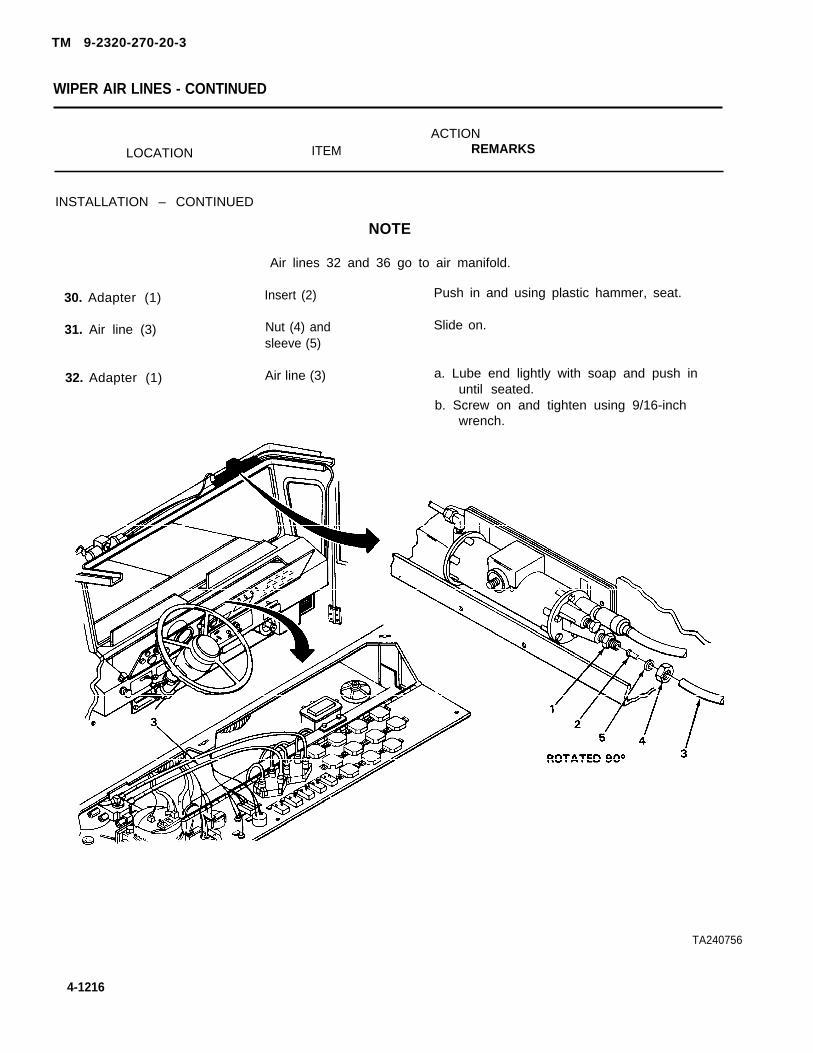
WIPER AIR LINES - CONTINUED
ACTION
LOCATION ITEM REMARKS
INSTALLATION – CONTINUED
30. Adapter (1)
31. Air line (3)
32. Adapter (1)
NOTE
Air lines 32 and 36 go to air manifold.
Insert (2) Push in and using plastic hammer, seat.
Nut (4) and Slide on.sleeve (5)
Air line (3) a. Lube end lightly with soap and push inuntil seated.
b. Screw on and tighten using 9/16-inchwrench.
TA240756
4-1216
TM 9-2320-270-20-3

TM 9-2320-270-20-3
WIPER AIR LINES - CONTINUED
ACTIONLOCATION ITEM REMARKS
33. Adapter (6) Insert (7) Push in and seat using plastic hammer,seat.
34. Air line (8) Nut (9) and Slide on.sleeve (10)
35. Adapter (6) Air line (8) a. Lube end lightly with soap and push inuntil seated.
b. Screw on and tighten using 9/16-inchwrench.
36. Screw (11) New loop clamp (12) Put on.
37. Loop clamp (12) Nut (14) Screw on and tighten using 3/8-inchto dashboard (13) wrench.
38. Air line (8) and Loop clamp (12) Using long nose pliers, put on.other air linesand wires (15)
39. New tie wrap (16) Using long nose pliers, put on.
TA240757
4-1217

TM 9-2320-270-20-3
WIPER AIR LINES - CONTINUED
ACTIONLOCATION ITEM REMARKS
INSTALLATION – CONTINUED
40. Side rail (1) Right inner roofpanel (2)
41. Right inner roof Six screws (3)panel (2) to siderail (1)
42. Side rail (4) Left inner roofpanel (5)
43. Left inner roof Five screws (6)panel (5) to siderail (4)
44. Left inner roof Air horn valve (7)panel (5)
45. Air horn valve (7) Two screws (8)to side rail (4)
46. Screw (9) Air horn chain (10)
47. Air horn chain (10) Screw (9)to side rail (4)
Put in place.
Screw in and tighten using number twocross-tip screwdriver.
Put in place.
Screw in and tighten using number twocross-tip screwdriver.
Put in place.
Screw in and tighten using 5/16-inch soc-ket and handle.
Put on.
Screw in and tighten using number twocross-tip screwdriver.
TA240758
4-1218

TM 9-2320-270-20-3
WIPER AIR LINES - CONTINUED
ACTIONLOCATION ITEM REMARKS
48.
49.
50.
51.
52.
53.
54.
Header (11)
Front inner roofpanel (12) toheader (11)
Wiper motors (14)
Wipe handles (15) towiper motors (14)
Front inner roofpanel (12)
Two sun visors (18)to front inner roofpanel (12)
Cab
Front inner roofpanel (12)
Seven screws (13)
Two handles (15)
Two nuts (16)
Two sun visors (18)
Four screws (19)
Instrument panel
Put in place.
Screw in and tighten using number twocross-tip screwdriver.
Put in place.
a. Screw on but do not tighten.b. Position handles (15) parallel to
wiper arms (17).c. Tighten nuts using 7/16-inch wrench.
Put in.
Screw in and tighten using number threecross-tip screwdriver.
Close (page 4-244).
NOTE
FOLLOW-ON MAINTENANCE: Check operation (TM 9-2320-270-20).
TA240759
4-1219
TASK ENDS HERE

TM 9-320-270-20-3
WIPER VENT LINES
This task covers:
a. Removal (page 4-1220)b. Installation (page 4-1223)
INITIAL SETUP
Tools Materials/Parts – Continued
Knife, pocket String (item 17, appendix C)Pliers, diagonal cutting Tape, pressure sensitive (item 21, appendix C)Pliers, slip-joint straight-nose Tape, teflon (item 22, appendix C)Screwdriver, cross-tip, number 2 Tubing, nylon air brakeScrewdriver; cross-tip, number 3 Wrap, tie (item 24, appendix C)Wrench, box, 7/16-inchWrench, open-end, 3/8-inch Personnel Required
OneMaterials/Parts
Equipment ConditionLoop clamp, air lines and wires to
dashboard Instrument panel open (page 4-244).
ACTIONLOCATION ITEM REMARKS
REMOVAL
Make sure all pressure is drained from air system before disconnecting air lines. Partsunder pressure can, when removed, fly off with great force causing injury to personnel.
NOTE
Steps in this task are the same for both right and left wiper vent lines. Right wiper ventl i n e i s s h o w n .
1. Air system Drain (TM 9-2320-270-10).
2. Front inner Four screws (2) Using number three cross-tip screwdriver,roof panel (1) and two sun visor unscrew and take off.
assemblies (3)
3. Two windshield wiper Two nuts (6) Using 7/16-inch wrench, unscrew and takehandles (4) to wiper off.motors (5)
4-1220
WARNING

TM 9-2320-270-20-3
WIPER VENT LINES - CONTINUED
ACTIONLOCATION ITEM REMARKS
4. Two wiper motors (5)
5. Front inner roofpanel (1) to header (7)
6. Header(7)
7. Right inner roofpanel (9) to siderail (10)
8. Side rail (10)
9. Check valve (12)
Two handles (4) Take off.
Seven screws (8) Using number two cross-tip screwdriver,unscrew and take off.
Front inner roof Take off.panel (1)
Six screws (11) Using number two cross-tip screwdriver,unscrew and take off.
Right inner roof Take off.panel (9)
Vent line (13) a.
b.c.d.e.
Using pocket knife, cut tape and takeoff.Get rid of tape.Pull off.Using pocket knife, notch end.Attach string to vent line (13) insidenotches.
TA240760
4-1221

TM 9-2320-270-20-3
WIPER VENT LINES - CONTINUED
ACTIONLOCATION ITEM REMARKS
REMOVAL - CONTINUED
10.
11.
12.
13.
14.
Grommet (1)
Vent line (2) toother air lines andwires (3)
Loop clamp (4) todashboard (5)
Screw (7)
Vent line (2) toother air lines andwires (3)
Vent line (2)
Loop clamp (4)
Nut (6)
Loop clamp (4)
Tie wraps (8)
Pull through.
Using cutting pliers, take out airlines and wires.
Using 3/8-inch open-end wrench, unscrewand take off.
a. Take off.b. Get rid of.
a. Using cutting pliers, cut and take off.b. Get rid of.
T A 2 4 0 7 6 1
4-1222

TM 9-2320-270-20-3
WIPER VENT LINES - CONTINUED
ACTIONLOCATION ITEM REMARKS
15. Header (9), side Vent line (2) a. Pull out.rail (10), hinge b. Take string off line (2).pillar (1 1), and c. Leave string in place.dashboard (12)
lNSTALLATiON
16. Vent line (2)
17. Dashboard (12), Vent line (2)hinge pillar (11),side rail (10),and header (9)
a.
b.c.
a.
b.c.
Using pocket knife, cut from bulk1/2-inch longer than old vent line (2).Using pocket knife, notch one end.Attach string to line in notches.
Using string, route vent line intoplace.Take off string.Using pocket knife, cut off vent linesquare behind notches.
TA240762
4-1223

TM 9-2320-270-20-3
WIPER VENT LINES - CONTINUED
ACTIONLOCATION ITEM REMARKS
INSTALLATION – CONTINUED
18. Check valve (1) Vent line (2)
19. Vent line (2) Check valve (1)
20. Grommet (3) Vent line (2)
21. Screw (4) New loop clamp (5)
22. Loop clamp (5) to Nut (7)dashboard (6)
23. Vent line (2) and Loop clamp (5)other air lines andwires (8)
24. New tie wraps (9)
Push on.
Using pressure sensitive tape, tapetogether.
Push through.
Put on.
Screw on and tighten using 3/8-inchwrench.
Using slip-joint pliers, put on.
Using slip-joint pliers, put on.
25. Side rail (10)
4-1224
Right inner roofpanel (11)
Put in place.
TA240763

TM 9-2320=270-20=3
WIPER VENT LINES - CONTINUED
ACTIONLOCATION ITEM REMARKS
28. Right inner roofpanel (11) to siderail (10)
27. Header (13)
28. Front inner roofpanel (14)
29.
30. Two sun visor assem-blies (16)
31. Two wipermotors (18)
32. Wiper handles (19)
33. C a b
Six screws (12)
Front inner roofpanel (14)
Seven screws (15)
Two sun visorassemblies (16)
Four screws (17)
Two handles (19)
Two nuts (20)
Instrument panel
Screw in and tighten using number twocross-tip screwdriver.
Put in place.
Screw in and tighten using number twocross-tip screwdriver.
Put in place.
Screw in and tighten using number threecross-tip screwdriver.
Put in place.
a. Screw on but do not tighten.b. Position handles (19) parallel to wiper
arms (21).c. Using 7/16-inch wrench, tighten.
Close (page 4-244).
TASK ENDS HERE
TA240764
4-1225

REAR VIEW MIRROR HEAD
This task covers:
a. Removal (page 4-1226)b. Installation (page 4-1226)
INITIAL SETUP
Tools Materials/Parts - Continued
Handle, ratchet, 3/8-inch drive Lockwasher, mirror assembly to bracketSocket, 7/16-inch, 3/8-inch drive (two required)Wrench, box, 7/16-inch
Personnel RequiredMaterials/Parts
TwoHead, mirror assemblyLockwasher, mirror assembly to
bracket (two required)
ACTIONLOCATION ITEM REMARKS
REMOVAL —
N O T E
Steps in this task are the same for both right and left rearview mirror heads. Right mirrorhead is shown.
1. Mirror head (1) to Nut (3), Iockwasher a.detent loop (2) (4), convex mirror
and bracket (5), b.spacer (6), lock-washer (7), andscrew (8)
Nut (9), Iockwasher a.(10), spacer (11),lockwasher(12), b.screw (13), andmirror head (1)
INSTALLATION
2.
Using box wrench, socket, and handle,unscrew and take out.Get rid of Iockwashers (4) and (7).
Using box wrench, socket, and handle,unscrew and take out.Get rid of Iockwashers (10) and (12).
3. New mirror head (1) Screw (13) and new Put through.Iockwasher(12)
4-1226
TM9-2320-270-20-3

TM 9-2320-270-20-3
REAR VIEW MIRROR HEAD - CONTINUED
ACTIONLOCATION ITEM REMARKS
4. Screw (13)
5. Detent loop (2)
6. Mirror head (1) todetent loop (2)
7. Screw (8)
8. Mirror head (1)
9. Screw(8)
10. Mirror head (1) todetent loop (2)
11.
12. Mirror head (1) todetent loop (2)
Spacer (11)
Screw (13) withmirror head (1)
New Iockwasher (10)and nut (9)
New Iockwasher (7’)
Screw (8)
Spacer (6) andconvex mirror andbracket (5)
New Iockwasher (4)and nut (3)
Mirror (1)
Two screws (8) and(13) and nuts (3)and (9)
Put on.
Put through.
Screw on but do not tighten.
Put on.
Put through part way.
Put in place and push screw (8) through.
Screw on but do not tighten.
With help from assistant, adjust.
Using box wrench, socket, and handle,tighten.
TASK ENDS HERE
TA240765
4-1227

TM 9-2320-270-20-3
CONVEX MIRROR HEAD
This task covers:
a. Removal (page 4-1228)b. Installation (page 4-1228)
INITIAL SETUP
Tools Materials/Parts
Handle, ratchet, 3/8-inch drive Lockwasher, convex mirror head to bracketPliers, slip-joint, straight-noseScrewdriver, cross-tip, number twoSocket, deep-well, 7/16-inch,
3/8-inch drive
ACTIONLOCATION ITEM REMARKS
REMOVAL
NOTE
Steps in this task are the same for both right and left convex mirrors. Right convex mirroris shown.
If mirror is not holding adjustment, use cross-tip screwdriver and tighten three screwson back of mirror.
1. Mirror(1) to Nut (3) and a. Using socket and handle, unscrew andbracket (2) Iockwasher (4) take off.
b. Get rid of lockwasher (4).You may have to hold ball shaftwith pliers.
2. Bracket (2)
3. Mirror (1)
INSTALLATION
4. New mirror (1)
5. Bracket (2)
6. Mirror (1) tobracket (2)
Mirror (1) Take out.
Washer (5) Take off.
Washer (5) Put on.
Mirror (1) Put in place.
New Iockwasher (4) Screw on and tighten using socketand nut (3) and handle.
4-1228

TM 9-2320-270-20-3
CONVEX MIRROR HEAD - CONTINUED
ACTIONLOCATION ITEM REMARKS
TASK ENDS HERE
MIRROR DETENT LOOP ASSEMBLY
This task covers:
a. Removal (page 4-1230)b. Installation (page 4-1230)
INITIAL SETUP
Tools
Handle, ratchet, 3/8-inch driveSocket, deep-well, 7/16-inch,
3/8-inch driveSocket, deep-well, 9/16-inch,
3/8-inch driveWrench, box, 7/16-inchWrench, box, 9/16-inch
Materials/Parts
Lockwasher, dent loop bracket to mirrormounting tube (four required)
Personnel Required
One
Equipment Condition
Rear view mirror head removed (page 4-1226).
TA240766
4-1229

TM 9-2320-270-20-3
MIRROR DETENT LOOP ASSEMBLY - CONTINUED
ACTIONLOCATION ITEM REMARKS
REMOVAL
NOTE
Steps in this task are the same for both right and left mirror detent loop assemblies.
1.
2
3.
Right mirror detent loop assembly is shown.
Detent loop (1) to Two screws (4), nutstwo brackets (2) (5), and springs (6)and (3)
Two brackets (2) Detent loop (1)and (3)
Two brackets (2) Four screws (8),and (3) to support nuts (9), andtube (7) Iockwashers (10)
INSTALLATION
4.
5.
6.
7.
Support tube (7)
Two brackets (2)and (3) to supporttube (7)
Two brackets (2)and (3)
Detent loop (1)to brackets (2)and (3)
Two brackets(2) and (3)
Four screws (8), newIockwashers (10),and nuts (9)
Detent loop (1)
Two screws (4),springs (6), andnuts (5)
Using 9/16-inch box wrench, 9/16-inchsocket, and handle, unscrew and takeout.
Take out.
a. Using 7/16-inch box wrench, 7/16-inch
b.
socket, and handle, unscrew and takeout.Get rid of Iockwashers (10)
Put in place and hold.
Screw in and tighten using 7/16-inch boxwrench, 7/16-inch socket, and handle.
Put in place.
Screw on and tighten using 9/16-inch boxwrench, 9/16-inch socket, and handle.
4-1230

TM 9-2320-270-20-3
MIRROR DETENT LOOP ASSEMBLY - CONTINUED
FOLLOW-ON MAINTENANCE:
TASK ENDS HERE
N O T E
Install rear view mirror head (page 4-1226).
TA240767
4-1231

TM 9-2320-270-20-3
MIRROR MOUNTING TUBE ASSEMBLY
This task covers:
a. Removal (page 4-1232)b. Installation (page 4-1236)
INITIAL SETUP
Tools
Extension, 5-inch, 3/8-inch driveHandle, ratchet, 1/4-inch driveHandle, ratchet, 3/8 inch drivePliers, slip-joint, straight-noseScrewdriver, cross-tip, number 2Socket, 5/16-inch, 1/4-inch driveSocket, 3/8-inch, 3/8-inch driveSocket, 7/16-inch, 3/8-inch driveSocket, 9/16-inch, 3/8-inch driveWrench, box, 7/16-inchWrench, open-end, 9/16-inchWrench, open-end, 7/8-inch
Materials/Parts – Continued
Lockwasher, front and rear outer crossbraces to support arm
Lockwasher, mounting tube bracket to twobrackets (four required)
Lockwasher, mirror mounting tube bracket toroof (two required)
Lockwasher, rear inner cross brace to bracketLockwasher, Left mirror mounting tube
bracket to roof (two required)
Personnel Required
OneMaterials/Parts
Lockwasher, front inner cross braceto bracket
Equipment Condtion
Rear view mirror removed (page 4-1226).Mirror detent loop assembly removed
(page 4-1229).
ACTIONLOCATiON ITEM REMARKS
REMOVAL
NOTE
Steps 1 thru 6 are the same for removing both right and left support arms. Right supportarm is shown.
4-1232

TM 9-2320-2704-20-3
MIRROR MOUNTING TUBE ASSEMBLY - CONTINUED
ACTIONLOCATION ITEM REMARKS
1. Two outer crossbraces (1) and(2) to two innercross braces(3) and (4)
2. Front inner crossbrace (4) tobracket (6)
3. Rear inner crossbrace (3) tobracket (10)
Two nuts (5) Using 7/8-inch wrench, unscrew part way.
Screw (7), nut (8), a.and Iockwasher (9)
b.
Screw (11), nut a.(12), and lock-washer (13)
b.
Using 9/16-inch open-end wrench,9/16-inch socket, and 3/8-inch drivehandle, unscrew and take out.Get rid of Iockwasher (9).
Using 9/16-inch open-end wrench,9/16-inch socket, and 3/8-inch drivehandle, unscrew and take out.Get rid of Iockwasher (13).
TA240768
4-1233

TM 9-2320-270-20-3
MIRROR MOUNTING TUBE ASSEMBLY - CONTINUED
ACTIONLOCATION ITEM REMARKS
REMOVAL– CONTINUED
4.
5.
6.
7.
8.
9.
10.
Support arm (1) Screw (2), nut (3),Iockwasher (4), andtwo outer crossbraces (5) and (6)
Support arm (1) Two wing screws (8)to mountingtube (7)
Mounting tube (7) Support arm (1)
Left support arm
a. Using 9/16-inch open-end wrench,9/16-inch socket, and 3/8-inch drivehandle, unscrew and take off.
b. Get rid of Iockwasher (4).
Unscrew and take out.You may have to use pliers to breakloose.
Pull out.
Repeat steps 1 to 6.and braces
Mounting tube (7) Four screws (10), a. Using 7/16-inch box wrench, 7/16-inchto two brackets (9) four nuts (11), socket, and 3/8-inch drive handle,
and four lock- unscrew and take off.washers (12) b. Get rid of Iockwashers (12).
Mounting tube (7) Two clamp Take off.plates (13)
Two brackets (9) Mounting Take off.tube (7)
TA240769
4-1234

TM 9-2320-270-20-3
MIRROR MOUNTING TUBE ASSEMBLY - CONTINUED
ACTIONLOCATION ITEM REMARKS
NOTE
Steps are the same for removing all four cross brace brackets. Right rear bracket isshown.
11. Cross brace Three screws (16) Using 3/8-inch socket, extension, andbracket (14) 3/8-inch drive handie, unscrew and taketo cowl (15) out.
12. Cowl (16) Cross brace Take off.bracket (14)
13. Three other Repeat steps 1cross bracebrackets (14)
1 and 12.
TA240770
4-1235

MIRROR MOUNTING TUBE ASSEMBLY - CONTINUED
ACTIONLOCATION ITEM REMARKS
REMOVAL– CONTINUED
14. Right inner roofside panel (1)to side rail (2)
15. Side rail (2)
16. Right mirrormounting tubebracket (4) toroof (5)
17. Air horn chain (9)to side rail (2)
18. Air horn valve (11)to side rail (2)
19.
20. Left inner roofpanel (13) toside rail (2)
21. Side rail (2)
22. Left mirror mountingtube bracket (15) toroof (5)
INSTALLATION
23. Roof (5)
24. Left mirrormounting tubebracket (15)to roof (5)
Six screws (3) Using cross-tip screwdriver, unscrew andtake out.
Right inner roofpanel (1)
Two screws (6),nuts (7), lock-washers (8),and bracket (4)
Screw (10) andchain (9)
Two screws (12)
Air horn valve (11)
Five screws (14)
Left inner roofpanel (13)
Two screws (16),nuts (17), lock-washers (18), andbracket (15)
Left mirrormounting tubebracket (15)
Two screws (16),new Iockwashers(18), and nuts (17)
Take out.
a. Using 7/16-inch box wrench, 7/16-inchsocket, extension, and 3/8-inch drivehandle, unscrew and take off.
b. Get rid of Iockwashers (8).
Using number two cross-tip screwdriver,unscrew and take off.
Using 5/16-inch socket and 1/4-inch drivehandle, unscrew and take out.
Allow to hang by air lines.
Using number two cross-tip screwdriver,unscrew and take out.
Take off.
a. Using 7/16-inch box wrench, socket,extension, and 3/8-inch drive handle,unscrew and take off.
b. Get rid of Iockwashers (18).
Put in place and hold.
Screw in and tighten using 7/16-inch boxwrench, socket, extension, and 3/8-inchdrive handle.
4-1236
TM 9-2320-270-20-3

TM 9-2320-270-20-3
MIRROR MOUNTING TUBE ASSEMBLY - CONTINUED
ACTIONLOCATION ITEM REMARKS
25. Side rail (2) Left inner roof Put in place and hold.panel (13)
26. Left inner roof Five screws (14) Screw in and tighten using number twopanel (13) to cross-tip screwdriver.side rail (2)
27. Left inner roof Air horn valve (11) Put in place.panel (13)
28. Air horn valve (11) Two screws (12) Screw in and tighten using 5/16-inchto side rail (2) socket and handle, 1/4-inch drive.
29. Screw (10) Air horn chain (9) Put on.
30. Air horn chain (9) Screw (10) Screw in and tighten using number twoto side rail (2) cross-tip screwdriver.
TA240771
4-1237

TM 9-2320-270-20-3
MIRROR MOUNTING TUBE ASSEMBLY - CONTINUED
ACTIONLOCATION ITEM REMARKS
INSTALLATION - CONTINUED
31. Roof (1)
32. Right mounting tubebracket (2) toroof (1)
33. Side rail (6)
34. Right inner roofpanel (7) to siderail (6)
Right mounting tube Put in place.bracket (2)
Two screws (3), new Screw in and tighten using 7/16-inch boxIockwashers (4), and wrench, 7/16-inch socket, and 3/8-inchnuts (5) drive handle.
Right inner roof Put in place.panel (7)
Six screws (8) Screw in and tighten using number twocross-tip screwdriver.
NOTE
Steps are the same for installing all four cross brace brackets. Right rear bracket isshown.
35. cowl (9) Cross brace Put in place.bracket (10)
36. Cross brace bracket Three screws (11) Screw in and tighten using 3/8-inch(lo) to cowl (9) socket, extension, and 3/8-inch drive
handle.
TA240772
4-1236

TM 9-2320-270-20-3
MIRROR MOUNTING TUBE ASSEMBLY - CONTINUED
LOCATION ITEMACTION
REMARKS
37. cowl (9) Other three cross Repeat steps 35 and 36.brace brackets (10)
38.
39.
Two brackets (12)
Mounting tube (13)
40. Two clamp plates(14) tobrackets (12)
Mounting tube (13) Put in place.
Two clamp Put in place.plates (14)
Four screws (15), Screw in and alternately tighten usingnew Iockwashers 7/16-inch box wrench, 7/16-inch socket,(16), and nuts (17) and 3/8-inch drive handle.
TA240773
4-1239

TM 9-2320-270-20-3
MIRROR MOUNTING TUBE ASSEMBLY - CONTINUED
ACTION
LOCATION ITEM REMARKS
INSTALLATION – CONTINUED
NOTE
Steps are the same for installing both right and left support arms. Right support arm isshown.
41. Mounting tube (1) Support arm (2) Push in until screw holes line up.
42. Support arm (2) to Two wing screws (3) Screw in and tighten by hand.
mounting tube (1)
43. Support arm (2) Two outer cross Put in place.braces (4) and (5)
44. Two cross braces Screw (6), new Screw in but do not tighten.
(4) and (5) to Iockwasher (7),support arm (2) and nut (8)
45. Rear cross brace Outer crossbracket (9) brace (4)
46. Outer cross brace Screw (10), new(4) to outer cross Iockwasher (11),brace bracket (9) and nut (12)
47. Front cross brace Outer crossbracket (13) brace (5)
a. Slide up or down until holes line up.b. Put in place.
Screw in and tighten using 9/16-inch open-end wrench, 9/16-inch socket, and 3/8-inch drive handle.
a. Slide up or down until holes line up.b. Put in place.
TA240774
4-1240

TM 9-2320-270-20-3
MIRROR MOUNTING TUBE ASSEMBLY - CONTINUED
ACTIONLOCATION ITEM REMARKS
48. Outer cross brace(5) to front crossbrace bracket (13)
49. Two outer crossbraces (4) and (5)
50. Two outer crossbraces (4) and (5)to support arm (2)
51.
FOLLOW-ON
TASK ENDS HERE
Screw (14), newlockwasher (15),and nut (16)
Two nuts (17)
Screw (6) andnut (8)
Left support armand cross tubes
Screw in and tighten using 9/16-inch open-end wrench, 9/16-inch socket, and 3/8-inch drive handle.
Using 7/8-inch wrench, tighten.
Using 9/16-inch open-end wrench, 9/16-inch socket, and 3/8-inch drive handle,tighten.
Repeat steps 41 to 50.
NOTE
MAINTENANCE: Install mirror detent loop assembly (page 4-1232).
TA240775
4-241
Ilul \/ ,, NI Ill

TM 9-2320-270-20-3
SPOTTER MIRROR HEAD AND BRACKET
This task covers:
a. Removal (page 4-1242)b. Installation (page 4-1243)
INITIAL SETUP
Tools Materials/Parts - Continued
Wrench, box, 1/2-inch Lockwasher, rod to radiator guardWrench, box, 15/16-inch Nut, self-locking, rod to radiator guardWrench, open-end, 1/2-inchWrench, open-end, 13/16-inch Personnel Required
Materials/Parts Two
Lockwasher, mirror head to rod(two required)
ACTIONLOCATION ITEM REMARKS
REMOVAL
1. Mirror head (1) torod (2)
2. Rod (2)
3.
4. Rod (2) to radiatorguard (7)
5. Radiator guard (7)
6. Rod (2)
Nut (3) and lock- s. Using 1/2-inch open-end and boxwasher (4) wrenches, unscrew and take off.
b. Get rid of Iockwasher (4).
Mirror head (1) a. Take off.and Iockwasher (5) b. Get rid of Iockwasher (5).
Nut (6) Unscrew and take off.
Self-locking nut (8) a. Using 15/16-inch box wrench, unscrewand take off.
c. Get rid of nut (8).
Rod (2) and lock-washer (9)
Nut (10)
a. Take off.b. Get rid of Iockwasher (9).
Using 15/16-inch box wrench, unscrew andtake off.
4-1242

TM 9-2320-270-20-3
SPOTTER MIRROR HEAD AND BRACKET - CONTINUED
ACTIONLOCATION ITEM REMARKS
INSTALLATION
7. Rod (2)
8.
9. Radiator guard (7)
10. Rod (2) to radiatorguard (7)
11. Rod (2)
12.
13.
14. Mirror head (1)to rod (2)
Nut (10)
New Iockwasher (9)
Rod (2)
New self-lockingnut (8)
Nut (10)
Nut (6)
New Iockwasher (5)and mirror head (1)
New Iockwasher (4)and nut (3)
Screw on, leaving 1/4-inch of threadsshowing between nut (10) and beginningof threads.
Put on.
Put in place.
Screw on and tighten using 15/16inchbox wrench.
Using 15/16-inch open-end wrench, un-screw part way, then tighten.
Screw on.
Put on.
Screw on finger tight.
TA240776
4-1243

TM 9-2320-270-20-3
SPOTTER MIRROR HEAD AND BRACKET - CONTINUED
ACTIONLOCATION ITEM REMARKS ,
INSTALLATION
15.
16.
17.
Rod (2) to radiatorguard (3)
Mirror head (1)to rod (2)
TASK ENDS HERE
Mirror head (1)and rod (2)
Nut (4)
Nut (5)
With help from assistant, adjust.
Using 15/16-inch box and open-endwrenches, tighten.
Using 1/2-inch open-end and boxwrenches, tighten.
AIR HORN VALVE
This task covers:
a. Removal (page 4-1245) d. Inspection/Replacement (page 4-1246)
b. Disassembly (page 4-1246) e. Assembly (page 4-1247)
c. Cleaning (page 4-1246) f. Installation (page 4-1248)
TA240777
4-1244

AIR HORN VALVE - CONTINUED
INITIAL SETUP
Tools
Hammer, plasticHandle, ratchet, 1/4-inch drivePliers, long-nose, roundPliers, slip-joint, straight-noseScrewdriver, cross-tip, number 2Socket, 5/16-inch, 1/4-inch driveViseWrench, open-end, 3/8-inchWrench, open-end, 9/16-inchWrench, open-end, 13/16-inch
TM 9-2320-270-20-3
Materials/Parts
Soap, liquid (Item 14, appendix C)Tag, marking (item 18, appendix C)Tape, teflon (item 22, appendix C)
Personnel Required
One
ACTIONLOCATION ITEM REMARKS
REMOVAL
WARNING
Make sure all pressure is drained from air system before disconnecting air lines. Partsunder pressure can, when removed, fly off with great force causing injury to personnel.
1. Air system Drain (TM 9-2330-270-10).
2. Chain (1) to left Screw (4) and Using cross-tip screwdriver, unscrew andinner roof panel (2) chain (1) take off.and side rail (3)
3. Valve arm (5) Chain (1) Using slip-joint and long-nose pliers,open last link and take off.
TA240778
4-1245

TM 9-2320-270-20-3
AIR HORN VALVE - CONTINUED
ACTION
LOCATION ITEM REMARKS
REMOVAL - CONTINUED
NOTE
Tag lines according to general maintenance instructions (page 4-1).
4. Adapter (1) Air line 38 (2) Using 9/16-inch wrench, unscrew and pullout.
5. Air line 38 (2) Insert (3) Using pliers, pull out.
or adapter (1)
6. Elbow (4) Air line 39 (5) Using 9/16-inch wrench, unscrew and pullout.
7. Air line 39 (5) Insert (6) Using long-nose pliers, pull out.
or elbow (4)
8. Valve (7) to side Two screws (9) Using 5/16-inch socket and handle, un-
rail (8) screw and take off.
9. Side rail (8) Valve (4) Take off.
DISASSEMBLY
10. Valve (7) Adapter (1) a. Secure valve (7) in vise.b. Using 9/16-inch and 13/16-inch
wrenches, unscrew and take out.
11. Elbow (4)
CLEANING
12. All parts
INSPECTION/REPLACEMENT
13. All parts
a. Using 3/8-inch wrench, unscrew andtake out.
b. Take valve (7) out of vise.
Clean according to general maintenanceinstructions (page 4-1).
Inspect according to general maintenanceinstructions (page 4-1).
4-1248

TM 9-2320-270-20-3
AIR HORN VALVE - CONTINUED
ACTIONL O C A T I O N ITEM REMARKS
ASSEMBLY
14. Valve (7) Elbow (4) a.b.
c.
a.
b.
Two inserts a.(3) and (6) b.
Adapter (1)15.
16. Elbow (4) andadapter (1)
Secure valve (7) in vise.Wrap threads with teflon tape(page 4-1).Screw in and tighten using 3/6-inchwrench.
Wrap threads with teflon tape(page 4-1).Screw in and tighten using 9/16-inchwrench.
Push in and using plastic hammer, seat.Take valve (7) out of vise.
TA240779
4-1247
. . . . . . . . .

AIR HORN VALVE - CONTINUED
ACTIONLOCATION ITEM REMARKS
INSTALLATION
17.
18.
19.
20.
21•
22.
23.
Left inner roof side Valve (2) Put in place.panel (1)
Valve (2) to leftinner roof sidepanel (1)
Elbow (4)
Adapter (6)
Arm (8)
Chain (9)
Left inner roofside panel (1)
Two screws (3) Screw in and tighten using 5/16-inchsocket and handle.
Air line 39 (5) a.
b.
Air line 38 (7) a.
b.
Chain (9) a.b.
Lube end lightly with soap and push inuntil seated.Screw on and tighten using 9/16-inchwrench.
Lube end lightly with soap and push inuntil seated.Screw on and tighten using 9/16-inchwrench.
Put through hole.Using slip-joint pliers. close.
Screw (10) Put through first link.
Screw (10) Screw in and tighten using screwdriver.
TA240780
4-1248
T M 9 - 2 3 2 0 - 2 7 0 - 2 0 - 3

TM 9-2320-270-20-3
AIR HORN VALVE - CONTINUED
FOLLOW-ON
TASK ENDS HERE
AIR HORN CHAIN
NOTE
MAINTENANCE: Check operation (TM 9-2320-270-10).
This task covers:
a. Removal (page 4-1249)b. Installation (page 4-1250)
INITIAL SETUP
Tools
Pliers, long-nose, roundPliers, slip-joint, straight noseScrewdriver, cross-tip, number 2
Personnel Required
One
ACTIONLOCATION ITEM REMARKS
REMOVAL
1. Chain (1) to left Screw (3) and Using screwdriver, unscrew and take out.inner roof panel (2) chain (1)
2. Valve arm (4) Chain (1) Using slip-joint and long-nose pliers,open last link and take off.
TA240781
4-1249

TM 9-2320-270-20-3
AIR HORN CHAIN - CONTINUED
ACTIONLOCATION ITEM REMARKS
INSTALLATION
3. Valve arm (1)
4. Left inner roofpanel (3)
New chain (2)
Screw (4) andchain (2)
a. Put through hole.b. Using slip-joint pliers, close.
Screw in and tighten using screwdriver.
TASK ENDS HERE
TA240782
4-1250

TM 9-2320-270-20-3
This task covers:
a. Removal (page 4-1252) e. Assembly (page 4-1255)b. Disassembly (page 4-1254) f. installation (page 4-1257)c. Cleaning (page 4-1254) g. Adjustment (page 4-1258)d. inspection/Replacement (page 4-1255)
INITIAL SETUP
Tools
Caps, vise-jaw, brassHammer, plasticKey, socket-head screw, 5/32-inchKnife, pocketKnife, puttyPliers, long-nose, roundScrewdriver, cross-tip, number 3Screwdriver, fiat-tip, 3/8-inchVise, machinist’sWrench, adjustable, 14-inchWrench, box, 1/2-inchWrench, open-end, 3/8-inchWrench, open-end, 9/16-inchWrench, open-end, 15/16-inchWrench, pipe, 1/4- to l-inch
Materials/Parts
Materials/Parts - Continued
Lockwasher, horn cover to body(eight required)
Lockwasher, horn tor roofSandpaper, medium grit (item 13,
appendix C)Soap, liquid (item 14, appendix C)Tape, tefion (item 22, appendix C)
Personnel Required
One
Cement, gasket (item 2, appendix C)Gasket, horn to roof
4-1251

TM 9-2320-270-20-3
AIR HORN - CONTINUED
ACTION
LOCATION ITEM REMARKS
REMOVAL
WARNING
Make sure all pressure is drained from air system before disconnecting air lines. Partsunder pressure can, when removed, fly off with great force causing injury to personnel.
1.
2. Elbow (1)
Air system
Air line 39 (2)
3. Air line 39 (2) or Insert (3)
elbow (1)
4. Coupling (4) Elbow (1)
5. Coupling (4) to Nut (6), washer (7),
roof (5) and spacer (8)
Drain (TM 9-2320-270-10).
Using 9/16-inch open-end wrench,unscrew and pull out.
Using pliers, pull out.
Using 3/8-inch open-end wrench, unscrewand take out.
Using 15/16-inch wrench, unscrew andtake out.
T A 2 4 0 7 8 3
4-1252

TM 9-2320-270-20-3
AIR HORN - CONTINUED
ACTIONLOCATION ITEM REMARKS
6. Horn (9) to Screw (10), washer a. Using 3/8-inch screwdriver and 1/2-roof (5) (11), spacer (12), inch box wrench, unscrew and take out.
nut (13), Iockwasher b. Get rid of Iockwasher (14).(14), and nut (15)
7. Roof (5) Horn (9) Lift off.
NOTE
Do not remove gasket unless it is leaking or you are installing a different horn assembly.
8. Gasket (16) Using putty knife and sandpaper, scrapeand sand off.
TA240784
4-1253

TM 9-2320-270-20-3
AIR HORN - CONTINUED
ACTION.
LOCATION ITEM REMARKS
DISASSEMBLY
NOTE
Except as noted, steps are the same for disassembling both right and left horn.However, do not mix parts. Right horn is shown,
9. Cover(1) tobody (2)
10. Body (2)
11.
12. Spring (6)
13. Cover (1)
14. Body (2)
15. Bell (11)
Do not remove
16. Body (2)
17.
CLEANING
18.
Four screws (3),four Iockwashers (4),and one tag (5)
Cover (1)
Spring (6), contact(7), and diaphragm (8)
Contact (7)
Spring seat (9) andnut (10)
Bell (11)
Screen (12)
a. Using cross-tip screwdriver, unscrewand take out.
b. Get rid of Iockwashers (4).Left horn does not have partnumber tag.
Lift off.
Take out.
Snap out.
Using 5/32-inch key, and 1/2-inchwrench, unscrew and take off.
Using adjustable wrench, unscrew and takeoff.
Using pocket knife, pry out.
C A U T I O N
coupling unless inspection shows need for replacement.
Coupling (13) Using pipe wrench, unscrew and take off.
Left horn (14) Repeat steps 9 thru 17.
All parts Clean according to general maintenanceinstructions (page 4-1).
4-1254

TM 9-2320-270-20-3
AIR HORN - CONTINUED
ACTIONLOCATION ITEM REMARKS
lNSPECTION/REPLACEMENT
19. All parts Inspect according to general maintenanceinstructions (page 4-1).
ASSEMBLY
NOTE
Except as noted, steps are the same for assembling both right and left horns. Right hornis shown.
20. Body (2) Coupling (13) a. Put body (2) in vise with jaw caps.b. Wrap 1/2 inch of threads with teflon
tape (page 4-1).c. Screw in and tighten using pipe wrench.d. Take body (2) out of vise.
21. Bell (11)
22. Body (2)
23. Cover (1)
24. Spring seat (9)
Screen (12)
Bell (11)
Spring seat (9)
Nut (10)
Snap into groove.
Screw in and tighten using adjustablewrench.
Screw in but do not tighten.
Screw on but do not tighten.
TA240785
4-1255

TM 9-2320-270-20-3
AIR HORN - CONTINUED
ACTION
LOCATION ITEM REMARKS
ASSEMBLY - CONTINUED
25. Spring (1)
28. Body (3)
27. Spring seat (5)
28. Body (3)
29. Cover (6) tobody (3)
30.
Contact (2)
Diaphragm (4)
Spring (1) andcontact (2)
Cover (6)
Four screws (7),new Iockwashers(8), and one tag (9)
Left horn (10)
Snap in.
Put in place.
Put in place.
Put in place.
Screw in and tighten using cross-tipscrewdriver.
Left horn does not have part numbertag.
Repeat steps 20 thru 29.
TA240786
4-1256

TM 9-2320-270-20-3
WARNING
AIR HORN - CONTINUED
ACTIONLOCATION ITEM REMARKS
INSTALLATION
NOTE
Skip step 31 if gasket was not removed,
Rubber cement and its fumes burn easily. Do not smoke or have open flame nearby whileusing. Use in well-ventilated area. Failure to observe these precautions can causeserious burns to personnel.
31. Roof (11) Gasket (12)
32. Horn (13)
33. Screw (14) Washer (15), spacer(16), and nut (17)
34. Horn (13) to Screw (14), newroof (11) Iockwasher (18), and
nut (19)
35. Coupling (20) Spacer (21), washer(22), and nut (23)
36. Horn (13) to Screw (14) androof (11) nut (19)
Apply cement and put in place.
Put in place.
Put on.
Screw on but do not tighten.
Screw on and tighten using 15/16-inchwrench.
Using 3/8-inch screwdriver and 1/2-inchbox wrench, tighten.
TA240787
4-1257

TM 9-2320-270-20-3
AIR HORN - CONTINUED
ACTIONLOCATION ITEM REMARKS
INSTALLATION – CONTINUED
37. Coupling (1) Elbow (2) a. Wrap threads with teflon tape(page 4-1).
b. Screw in and tighten using 3/8-inchwrench.
Push in and using plastic hammer, seat.
a. Lube end lightly with soap and push inuntil seated.
b. Screw on and tighten using 9/16-inchwrench.
38. Elbow (2)
39.
Insert (3)
Air line 39(4)
ADJUSTMENT
WARNING
Hearing protection must be worn while adjusting air horns. Air horns are very loud. Ifhearing protection is not worn, permanent ear damage could result.
40. Engine a. Start engine and charge air system tonormal pressure (TM 9-2320-270-10).
b. Shut down engine(TM 9-2320-270-10).
41. Right horn (5) Spring seat (6) and a. Using 5/32-inch key and 1/2-inchnut (7) wrench, unscrew nut part way.
b. Using 5/32-inch key, unscrew seat (6)as far out as it will go.
42. Air horn valve (8) Chain (9) Pull, sounding horn as many times asneeded to adjust. TA240788
4-1258

TM 9-2320-270-20-3
AIR HORN - CONTINUED
LOCATIONACTION
ITEM REMARKS
43. Right horn (5) Spring seat (6) a. Using 5/32-inch key, screw seat (6)and nut (7) in until horn sounds clear.
b. Using 5/32-inch key and 1/2-inchwrench, tighten nut (7).
44. Air horn valve (8) Chain (9) Sound horn again to make sure adjustmentis the same.
45. Left horn (10) Repeat steps 40 thru 44 for left horn.
TASK ENDS HERE
TA240789
4-1259

TM 9-2320-270-20-3
AIR HORN AIR LINES
This task covers:
a. Removal (page 4-1260) c. Installation (page 4-1262)b. Repair (page 4-1262)
INITIAL SETUP
Tools
Hammer, plasticKnife, pocketPliers, diagonal-cuttingPliers, long-nose, roundPliers, slip-joint, straight-noseWrench, open-end, 9/16-inch
Materials/Parts
Sleeve, compression, tube, 1/4-inchinside diameter (two required)
Materials/Parts – Continued
Soap, liquid (item 14, appendix C)Tag marking (item 18, appendix C)Tubing, nylon air brake, 1/4-inch OD
(as required)Wrap, tie (item 24, appendix C)
Personnel Required
One
ACTIONLOCATION ITEM REMARKS
REMOVAL
WARNING
Make sure ail pressure is drained from air system before disconnecting air lines. Partsunder pressure can, when removed, fly off with great force causing injury to personnel.
NOTE
Tag lines according to general maintenance instructions (page 4-1).
1.
2. Elbow (1)
3. Air line 39 (2)or elbow (1)
Air system Drain (TM 9-2320-270-10).
Air line 39 (2) Using 9/16-inch wrench, unscrew and pullout.
insert (3) Using long-nose pliers, pull out.
4-1260

TM 9-2320-270-20-3
AIR HORN AIR LINES - CONTINUED
ACTIONLOCATION ITEM REMARKS
4. Elbow (4) Air line 39 (2) Using 9/16-inch wrench, unscrew and pullout.
5. Air line 39 (2) Insert (5) Using long-nose pliers, pull out.or elbow (4)
6. Air line 39 (2) Two nuts (6) Using pocket knife, cut line (2) andslide off.
7. Cab Instrument panel Open (page 4-244).
TA240790
4-1261

TM 9-2320-270-20-3
AIR HORN AIR LINES - CONTINUED
ACTIONLOCATION ITEM REMARKS
REMOVAL - CONTINUED
8. Air line 38 (1)to other air linesand wires (2)
9. Adapter (4)
10. Air line 38 (1)or adapter (4)
11. Adapter (6)
12. Air line 38 (1)or adapter (6)
13. Air line 38 (1)
14.
15. Hinge pillar (10)and dashboard (11)
16. Air line 38 (1)
REPAIR
Two tie wraps (3)
Air line 38 (1)
insert (5)
Air line 38(1)
insert (7)
Sleeve (8)
Nut (9)
Air line 38 (1)
Nut (12)
a. Using cutting pliers, cut.b. Get rid of.
Using 9/16-inch wrench, unscrew and pullout.
Using long-nose pliers, pull out.
Using 9/16-inch wrench, unscrew and pullout.
Using long-nose pliers, pull out.
a. Using pocket knife, cutoff at valveend.
b. Get rid of.
Silde off.
a. Attach string at valve end.b. Using string, pull out from manifoid
end.c. Untie string and leave in pillar (10).
Slide off.
NOTE
To repair air horn air lines, see Nylon Tubing Repair (page 4-634).
INSTALLATION
17. Dashboard (11) and New air line 38(1) a. Using pocket knife, cut from bulkhinge pillar (10) stock 1/2 inch longer than old air
line (1).b. Attach string to end.c. Using string, route into place.d. Remove string.
4-1262

TM 9-2320-270-20-3
AIR HORN AIR LINES - CONTINUED
LOCATION ITEMACTION
REMARKS
18. Air line 38 (1)
19. Adapter (6)
20.
Nut (9) and newsleeve (8)
Insert (7)
Air line 38(1)
21. Adapter (4)
22. Air line 38 (1)
23. Adapter (4)
24. Air line 38 (1)to other linesand wires (2)
Insert (5)
Nut (12) and newsleeve (13)
Air line 38(1)
Two tie wraps (3)and wires (2)
Slide on valve end.
Push in and using plastic hammer, seat.
a. Lube end lightly with soap and push inuntil seated.
b. Screw on and tighten using 9/16-inchwrench.
Push in and using plastic hammer, seat.
Slide on.
a. Lube end lightly with soap and push inuntil seated.
b. Screw on and tighten using 9/16-inchwrench.
Using slip-joint pliers, put on.
TA240791
4-1263

TM 9-2320-270-20-3
AIR HORN AIR LINES - CONTINUED
ACTION
LOCATION ITEM REMARKS
INSTALLATION - CONTINUED
25. Cab Instrument panel Close.
28. New air line 39 (1) Using pocket knife, cut from bulk stocksame length as old air line 39 (l).
27. Two elbows (2) Two inserts (4) Push in and using plastic hammer, seat.
and (3)
28. Air line 39(1) Nut (5) and new Slide on.sleeve (6)
29. Elbow (2) Air line 39 (1) a. Lube end lightly with soap and push inuntil seated.
b. Screw on and tighten using 9/16-inchwrench.
30. Air line 39(1) Nut (5) and Slide on.new sleeve (6)
31. Elbow (3) Air line 39 (1) a.
b.
Lube end Iightly with soap and push inuntil seated.Screw on and tighten using 9/16-inchwrench.
TA240792
4-1284

TM 9-2320-270-20-3
AIR HORN AIR LINES - CONTINUED
NOTE
FOLLOW-ON MAINTENANCE: Check operation (TM 9-2320-270-10).
TASK END HERE
HEATER CORE
This task covers:
a. Removal (page 4-1266)b. Installation (page 4-1266)
INITIAL SETUP
Tools Personnel Required
Handle, speeder, 1/4-inch drive OnePan, drainSocket, 1/4-inch, 1/4-inch drive Equipment ConditionScrewdriver, flat-tip, 3/16-inchScrewdriver, flat-tip, 1/4-inch Right side of hood open and right hood side
panel removed (TM 9-2320-270-10).Materials/Parts
Rags, wiping (item 10, appendix C)
4-1265

TM 9-2320-270-20-3
HEATER CORE - CONTINUED
ACTIONLOCATION ITEM REMARKS
REMOVAL
WARNING
Be careful when removing radiator cap. If engine is hot, escaping steam could burnyou. Using a rag, cover radiator cap to protect your hand. Unscrew cap just enough toallow any built-up steam to escape. When all pressure has been relieved, unscrew capthe rest of the way, and take off of radiator.
1.
2.
3.
4.
5.
6.
7.
Radiator (1)
Heater hose (4) tonipple (5)
Nipple (5)
Return hose (7) tonipple (8)
Nipple (8)
Two nipples (5)and (8)
Radiator cap (2)
Draincock (3)
Clamp (6)
Heater hose (4)
Clamp (9)
Return hose (7)
Two grommets (10)
a.
b.
a.b.c.d.
Slowly unscrew to first stop, pause,and allow pressure escape.When all pressure has escaped,unscrew and take off.
Place drain pan underneath.Open and let coolant drain.When coolant stops draining, close.Get rid of coolant (page 4-1).
Using 1/4-inch flat-tip screwdriver, un-screw and pull back.
Pull off.
Using 1/4-inch flat-tip screwdriver, un-screw and pull back.
Pull off.
Pull off.
4-1266

TM 9-2320-270-20-3
HEATER CORE - CONTINUED
LOCATION ITEMACTION
REMARKS
8. Cover (11) to Four screws (13)heater (12) with captive
Iockwashers
9. Heater (12) Cover (11)
10. Heater core (14) to Four screws (15)heater (12) with captive
Iockwashers
N O T E
Step 11 is necessary only if your
11. Access cover (16) Two screws (17)
12 Heater (12)
N O T E
There will still be some
Heater core (14)
Using 1/4-inch socket and handle, unscrewand take out.
Some covers may use five screws.
Take off.
Using 1/4-inch socket and handle, unscrewand take out.
heater has access cover.
Using 3/16-inch screwdriver, unscrew andtake out.
coolant in core.
a. Pull out.b. Using rags, wipe up spilled coolant.
TA240794
4-1267

TM 9-2320-270-20-3
HEATER CORE - CONTINUED
ACTIONLOCATION ITEM REMARKS
INSTALLATION
13. Heater (1) Heater core (2) Push into place.
14. Heater core (2) to Four screws (3) Screw in and tighten using 1/4-inchheater (1) with captive socket and handle.
Iockwashers
15. Heater (1) Cover (4) Push into place.
16. Cover (4) to Four screws (5) Screw in and tighten using 1/4-inch socketheater (1) with captive and handle.
Iockwashers Some covers may use five screws.
NOTE
Step 17 is necessary only if heater has access cover.
17. Access cover (6)
18. Two nipples (8)and (9)
19. Nipple (8)
20. Return hose (11) tonipple (8)
21. Nipple (9)
22. Heater hose (13) tonipple (9)
23.
Two screws (7) Screw in and tighten using 3/16-inchflat-tip screwdriver.
Two grommets (10) Push into place.
Return hose (11) Push on until seated.
Clamp (12) a. Put in place over nipple (8).b. Using 1/4-inch flat-tip screwdriver,
tighten.
Heater hose (13) Push on until seated.
Clamp (14) a. Put in place over nipple (9).b. Using 1/4-inch flat-tip screwdriver,
tighten.
Cooling system Fill (TM 9-2320-270-10).
4-1288

TM 9-2320-270-20-3
HEATER CORE - CONTINUED
N O T E
FOLLOW-ON MAINTENANCE:
1. Check operation (TM 9-2320-270-10).2. Close right side of hood and install right hood side panel (TM 9-2320-270-10).
TASK ENDS HERE
TA240795
4-1269

TM 9-2320-270-20-3
HEATER MOTOR
This task covers:
a. Removal (page 4-1270)b. installation (page 4-1270)
INITIAL SETUP
Tools Personnel Required
Handle, speeder, 1/4-inch drive OneSocket, 1/4-inch, 1/4-inch driveScrewdriver, fiat-tip, 3/16-inch Equipment Condition
Materiais/Parts Battery ground cable disconnected(page 4-444).
Lockwasher, wire to suppressor
REMOVAL
1.
2.
3.
4.
5.
6.
ACTIONLOCATION ITEM REMARKS
Red wire toswitch (1)
Red wire tomotor (3) tosuppressor (4)
Suppressor (4) toheater (7)
Black wire (9) toheater (7)
Motor assembly (11)to heater (7)
Heater (7)
INSTALLATION
7. Heater (7)
8. Motor assembly(11)to heater (7)
9. Screw (10)
4-1270
Red wire tosuppressor (2)
Screw (5), iock-washer (6), andwire (3)
Screw (8) andsuppressor (4)
Screw (10) andwire (9)
Three screws (12)
Motor assembly(11)
Motor assembly(11)
Three screws (12)
Black wire (9)
Unplug.
a. Using screwdriver, unscrew and takeout.
b. Get rid of lockwasher (6).
Using 1/4-inch socket and handle, unscrewand take off.
Using 1/4-inch socket and handle, unscrewand take off.
Using 1/4-inch socket and handle, unscrewand take out.
Take out.
Place in position.
Screw in and tighten using 1/4-socket and handle.
Put on.
inch

TM 9-2320-270-20-3
HEATER MOTOR - CONTINUED
LOCATION ITEMACTION
REMARKS
10. Black wire (9) to Screw (10)heater (7)
Screw in and tighten using 1/4-inchsocket and handle.
NOTE
Make sure suppressor is installed and connections are correct.
11. Heater (7) Suppressor (4) Put in place and hold.
12 Suppressor (4) to Screw (8) Screw in and tighten using 1/4-inchheater (7) socket and handle.
13. Screw (5) New lockwasher (6) Put on.and red wire tomotor (3)
14. Suppressor (4) Screw (5) Screw in and tighten using screwdriver.
15. Red wire to Red wire to Plug in.switch (1) suppressor (2)
16. Battery ground cable Connect (page 4-444) and check operation(TM 9-2320-070-10).
TASK ENDS HERE
TA240796
4-1271

TM 9-2320-270-20-3
DEFROSTER KNOB AND CABLE
This task covers:
a. Removal (page 4-1272)b. Installation (page 4-1273)
INITIAL SETUP
Tools Personnel Required
Pliers, slip-joint, straight-nose One
Screwdriver, cross-tip, number 1Screwdriver, flat-tip, 1/8-inchWrench, open-end, 5/8-inch
ACTION
LOCATION ITEM REMARKS
REMOVAL
1. Knob (1) to Setscrew (3) Using flat-tip screwdriver, unscrew
cable (2) part way.
2. Cable (2) Knob (1) Pull off.
3. Cable (2) to heater Nut (5) Using 5/8-inch wrench, unscrew and take
control panel (4) off.
4. Dashboard (6) Cable (2) Pull out from behind.
5. Cable (2) to de- Spring washer (8) Using slip-joint pliers, pull off.
froster door arm (7)
6. Cable clip (9) to Screw (11) Using cross-tip screwdriver, unscrew and
cable support (10) take out.
7. Cable support (10) Cable clip (9) Pull up and off.
8. Defroster door Defroster cable (2) Pull off and take out.
arm (7)
4-1272

TM 9-2320-270-20-3
DEFROSTER KNOB AND CABLE - CONTINUED
ACTIONLOCATION ITEM REMARKS
INSTALLATION
9.
10.
11.
12.
13.
14.
CAUTION
When installing defroster cable, do not bend cable tighter than 4 1/2 inches. Wire insidecable will kink and cable will be damaged.
Dashboard (6) Cable (2) Route behind and push in from behind.
Cable (2) to heater Nut (5) Screw on but do not tighten.control panel (4)
Cable (2) Knob (1) With cable shaft pulled out, push on.
Knob (1) to Setscrew (3) a. Using flat-tip screwdriver, tighten.cable (2) b. Push knob (1) in.
Defroster door Defroster cable (2) Push on.arm (7)
Cable (2) to Spring washer (8) Using pliers, push on.defroster doorarm (7)
TA240797
4-1273

TM 9-2320-270-20-3
DEFROSTER KNOB AND CABLE - CONTINUED
ACTION
LOCATION ITEM REMARKS
INSTALLATION – CONTINUED
15. Cable support (1) Cable (2)
16. Cable (2) tosupport (1)
17. Cable clip (5) tosupport (1)
18. Cable (2) to heatercontrol panel (7)
Cable clip (5)
Screw (6)
Nut (8)
a. Make sure defroster knob(3) is pushedin.
b. Make sure defroster door arm (4) is allthe way to the left.
c. Put cable (2) in place.
a. Hook tab in hole.b. Snap on.
Screw in and tighten using cross-tipscrewdriver.
NOTE
FOLLOW-ON MAINTENANCE: Check operation (TM 9-2320-270-10).
TASK ENDS HERE TA240798
4-1274

TM 9-2320-270-20-3
HEATER ASSEMBLY
This task covers:
a. Removal (page 4-1286) c. Assembly (page 4-1279)— b. Disassembly (page 4-1278) d. installation (page 4-1280)
lNITIAL SETUP
Tools
Extension, 12-inch, 3/8-inch driveHandle, ratchet, 3/8-inch drive
(two required)Handle, speeder, 1/4-inch drivePliers, diagonal-cuttingPliers, slip-joint, straight-noseScrewdriver, cross-tip, number oneSocket, 1/4-inch, 1/4-inch driveSocket, deep-well, 7/16-inch, 3/8-
inch driveSocket, 7/16-inch, 3/8-inch drive
Materiais/Parts
Cement, rubber (item 3, appendix C)
Materials/Parts - Continued
Lockwasher, heater assembly to firewall(four required)
Naptha (item 9, appendix C)Tag, marking (item 18, appendix C)Wrap, tie (item 24, appendix C)
Personnel Required
One
Equipment Condition
Battery ground cable disconnected(page 4-444).
Heater core removed (page 4-1265).
4-1275

TM 9-2320-270-20-3
HEATER ASSEMBLY - CONTINUED
ACTION
LOCATION ITEM REMARKS
REMOVAL
NOTE
Tag wires according to general maintenance instructions (page 4-1).
1.
2.
3.
4.
5.
6.
7.
8.
Red switch wire (1)
Resistor (3)
Defroster cable(5) to defrosterdoor arm (6)
Cable clip (8) tocable support (9)
Cable support (9)
Defroster doorarm (6)
Two defroster hoses(11) to heater (12)
Heater (12)
Red wire tosuppressor (2)
Red switch wire (1)and orange switchwire (4)
Spring washer (7)
Screw (10)
Cable clip (8)
Defroster cable (5)
Two tie wraps (13)
TWO defrosterhoses (11)
Unplug.
Unplug.
Using slip-joint pliers, pull off.
Using cross-tip screwdriver, unscrew andtake out.
Pull up and snap off.
Pull off.
Using cutting pliers, cut and take off.
Pull off.
TA240799
4-1276

TM 9-2320-270-20-3
HEATER ASSEMBLY- CONTINUED
ACTIONLOCATION ITEM REMARKS
9. Heater (hidden) Two screws (15) Using 7/16-inch socket, extension, andto firewall (14) handle, hold.
10. Two screws (15) Two nuts (16), With help from assistant and using 7/16-Iockwashers (17), inch deep-well socket and handle, unscrewand washers (18) and take off.
11. Firewall (14) Two screws (15) Take out.
12. Two studs (19) Two nuts (20), With help from assistant and using 7/16-Iockwashers (21), inch deep-well socket and handle, unscrewwashers (22), and and take off.one wire clip (23)
13. Lockwashers (17) Get rid of.and (21)
TA240800
4-277

TM 9-2320-270-20-3
HEATER ASSEMBLY - CONTINUED
ACTIONLOCATION ITEM REMARKS
REMOVAL - CONTINUED
14. Firewall (1) Heater (2) Take out.
DISASSEMBLY
15. Resistor (3) toheater (2)
16. Heater (2)
17.
18. Air deflector (5)to heater (2)
19. Heater (2)
Two screws (4)
Resistor (3)
Heater motor andheater motorsuppressor
Two screws (6)
Air deflector (5)
Using 1/4-inch socket and speeder handle,unscrew and take out.
Take out.
Remove (pages 4-1270 and 4-1316).
Using number one cross-tip screwdriver,unscrew and take out.
Take off.
TA240801
4-1278

TM 9-2320-270-20-3
HEATER ASSEMBLY - CONTINUED
ACTIONLOCATION ITEM REMARKS
20. Heaterdeflector (7)
Using number one cross-tip screwdriver,unscrew and take out.
21. Heater (2)
ASSEMBLY
22. Heater (2)
23. Heaterdeflector (7)to heater(2)
24. Heater (2)
25. Air deflector (5)to heater(2)
26. Heater (2)
27.
28. Resistor (3) toheater (2)
Three screws (8)
Heaterdeflector (7)
Heaterdeflector (7)
Three screws (8)
Air deflector (5)
Two screws (6)
Heater motor andheater motorsuppressor
Resistor (3)
Two screws (4)
Take off.
Put in place.
Screw in and tighten using number onecross-tip screwdriver.
put in place.
Screw in and tighten using number onecross-tip screwdriver.
Install (pages 4-2170 and 4-1316).
Put in place.
Screw in and tighten using 1/4-inch socketand speeder handle.
TA240802
4-1279

TM 9-2320-270-20-3
HEATER ASSEMBLY - CONTINUED
ACTION
LOCATION ITEM REMARKS
INSTALLATION
W A R N I N G
Naptha and its fumes are harmful and flammable. Do not smoke or use near open flamewhile using. Use only in well-ventilated area. Naptha can catch fire and fumes canexplode causing serious injury.
Rubber cement and its fumes burn easily. Do not smoke or have open flame nearby whileusing. Use in well-ventilated area. Failure to observe these precautions can causeserious burns to personnel.
29. Heater (1)
30. Firewall (3)
Two foam pads (2) a. Peel off.b. Using rags and naptha, clean.c. Using naptha) rags! and sandpaper
area where pads (2) attach.d. Apply rubber cement and glue on new
pads (2).
Heater (1) Place in position over intake (4).
TA240803
4-1230

TM 9-2320-270-20-3
HEATER ASSEMBLY - CONTINUED
ACTIONLOCATION ITEM REMARKS
31. TWO studs (5) Wire clip (6), two With help from assistant, screw on andwashers (7), new tighten using 7/16-inch deep-well socketIockwashers (8), and handle.and nuts (9)
32. Firewall (3) TWO screws (10), With help from assistant, screw on andwashers (11), new tighten using 7/16-inch and deep-wellIockwashers (12), sockets, exension, and two handles.and nuts (13)
.
TA240804
4-1281

TM 9-2320-270-20-3
HEATER ASSEMBLY - CONTINUED
ACTION
LOCATION ITEM REMARKS
INSTALLATION - CONTINUED
33. Heater (1)
34. Two defroster hoses(2) to heater(1)
35. Defroster doorarm (4)
36. Cable support (6)
37. Defroster cable (5)
38. Cable clip (7) tocable support (6)
39. Defroster cable(5) to arm (4)
40. Terminal (10)
41. Terminal (12)
42. Red switch wire (13)
Two defrosterhoses (2)
Two new tiewraps (3)
Defroster cable (5)
Defroster cable (5)
Cable clip (7)
Screw (8)
Spring washer (9)
Orange switchw i re (n )
Red switch wire (13)
Red wire tosuppressor (14)
Push on.
Using slipjoint pliers, put on.
a. Push knob (6) in.b. Push arm (4) all the way left.c. Put loop on end on.
Put in place.
With arm (4) all the way left, put on.
Screw in and tighten using cross-tipscrewdriver.
Push on.
Push on.
Push on.
Push on.
4-1282

TM 9-2320-270-20-3
HEATER ASSEMBLY - CONTINUED
FOLLOW-ON MAINTENANCE:
1. Install heater core (page 4-1265).2. Connect battery ground cable (page 4-444).
TA240805
4-1283
TASK ENDS HERE
NOTE

HEATER KNOB AND CABLE
This task covers:
a. Removal (page 4-1284)b. Installation (page 4-1286)
INITIAL SETUP
Tools
Handle, speeder, 1/4-inch drivePliers, diagonal-cuttingPliers, long-nose, roundPliers, slip-joint, straight-noseScrewdriver, flat-tip, 1/8-inchSocket, 1/4-inch, 1/4-inch driveWrench, open-end, 5/8-inch
Personnel Required
Two
Equipment Condition
Right side of hood open and right hood sidepanel removed (TM 9-2320-270-10).
Materials/Parts
Wrap, tie (item 24, appendix C)
ACTION
LOCATION ITEM REMARKS
REMOVAL
1. Cable (1) toheater shutoffvalve (2)
2.
3. Shutoff valve (2)
4. Cable (1) toheater hoses (6)or wires (7)
Screw (3) onswivel (4)
a. Using long-nose pliers, straightencable (1).
b. Using 1/8-inch screwdriver, unscrewbut do not take out.
Clamp screw (5) Using 1/4-inch socket and handle, un-screw but do not take out.
Cable (1) Pull out.
Tie wraps (8) a. Using cutting pliers, cut and take off.b. Get rid of.
Number of ties will vary betweentrucks.
5. Loop clamp(9) Cable (1) Pull out.
4-1284
TM9-2320-270-20-3

TM 9-2320-270-20-3
HEATER KNOB AND CABLE- CONTINUED
ACTIONLOCATION ITEM REMARKS
6. Heater knob (10)to cable (1)
7. Cable (1)
8. Cable (1) to heatercontrol panel (12)
9. C a b
10. Heater controlpanel (12)
Setscrew (11) Using 1/8-inch screwdriver, unscrew butdo not take out.
Knob (10) Take off.
Nut (13) Using 5/8-inch wrench, unscrew and takeoff.
Instrument panel Open (page 4-244).
Cable (1) a. Pull out from behind.b. With help from assistant, pull out
from engine area.
TA240806.
4-1285

TM 9-2320-270-20-3
HEATER KNOB AND CABLE - CONTINUED
ACTION
LOCATION ITEM REMARKS
INSTALLATION
11.
12.
13.
14.
15.
16.
Grommet (1)
Heater controlpanel (3)
Cable (2) to heatercontrol panel (3)
Cable (2)
Knob (5) tocable (2)
Cab
Cable (2) Route through cab side and with help fromassistant, pull into engine area.
Cable (2) Push into place from behind.
Nut (4) Screw on and tighten using 5/8-inchwrench.
Knob (5) With shaft pulled out, push on.
Setscrew (6) a. Using 1/8-inch screwdriver, tighten.b. Push in knob (5).
instrument panel Close (page 4-244).
17. Shutoff valve (7) Cable (2)and swivel (8)
a. Route into place.b. With lever (9) turned toward front,
route through clamp (10) and pushwire (11) through.
TA240807
4-1286

TM 9-2320-270-20-3
HEATER KNOB AND CABLE - CONTINUED
LOCATION ITEMACTION
REMARKS
18. Cable (2) to Setscrew (12)swivel (8)
a. Using long-nose pliers, bend end over.b. Using 1/8-inch screwdriver, tighten.
19. Cable (2) to shut- Clamp screw (13)off valve (7)
20. Cable (2) to heater New tie wraps (17)hoses (15) andwires (16)
With clamp (10) over conduit (14), andusing 1/4-inch socket and handle, tighten.
Using slip-joint pliers, put on.
FOLLOW-ON MAINTENANCE:
1. Check operation (TM 9-2320-270-10).2. Close right side of hood and install right hood side panel (TM 9-2320-270-10).
TASK ENDS HERE
TA240808
4-1287
N O T E

TM 9-2320-270-270-20-3
HEATER DEFLECTOR
This task covers:
Replacement (page 4-1288)
INITIAL SETUP
Tools Personnel Required
Screwdriver, cross-tip, number 1 One
Screwdriver, offset, cross-tip, number 1
ACTION
LOCATION ITEM REMARKS
REPLACEMENT
1. Deflector (1) toheater (2)
2.
3. Heater (2)
4.
5. Deflector (1) toheater (2)
6.
Screw (3)
TWO screws (4)
Deflector (1)
New deflector (1)
Two screws (4)
Using offset screwdriver, unscrew and takeout.
Using cross-tip screwdriver, unscrew andtake out.
Take off.
Put in place.
Screw in and tighten using cross-tipscrewdriver.
Screw (3) Screw in and tighten using offsetscrewdriver.
—
TASK ENDS HERETA240809
4-1288

TM 9-2320-270-20-3
DEFROSTER NOZZLE
This task covers:
a. Removal (page 4-1289)b. Installation (page 4-1290)
INITIAL SETUP
Tools Materials/Parts
Pliers, diagonal-cutting Wrap, tie (item 24, appendix C)Pliers, slip-joint, straight-noseScrewdriver, cross-tip, number 1 Personnel Required
One
ACTIONLOCATION ITEM REMARKS
REMOVAL
Steps in this
1. C a b
2. Hose (1) tonozzle (2)
3. Nozzle (2)
4. Dashboard (4)
N O T E
task are the same for right and left defroster nozzles.
Instrument panel Open (page 4-244).
Tie wrap (3) a. Using cutting pliers, cut and take off.b. Get rid of.
Hose (1) Pull off.
TWO screws (5), a. Using cross-tip screwdriver, unscrewIockwashers (6), and take off.and nozzle (2) b. Get rid of Iockwashers (6).
TA24O81O
4-1289

TM 9-2320-270-20-3
DEFROSTER NOZZLE - CONTINUED
ACTIONLOCATION ITEM REMARKS
INSTALLATION
5. Dashboard (1)
6. Nozzle (2) todashboard (1)
7. Nozzle (2)
8. Hose (5) tonozzle (2)
9. C a b
Nozzle (2)
Two screws (3) andnew Iockwashers (4)
Hose (5)
New tie wrap (6)
Instrument panel
Put in place.
Screw in and tighten using cross-tipscrewdriver.
Push on.
Using slip-joint pliers, put on.
Close (page 4-244).
N O T E
FOLLOW-ON MAINTENANCE: Check operation (TM 9-2320-27-10).
DEFROSTER HOSE
.This task covers:
a. Removal (page 4-1291)b. Installation (page 4-1292) .
TA240811
4-1290
TASK ENDS HERE

TM 9-2320-270-20-3
DEFROSTER HOSE - CONTINUED
INITIAL SETUP
Tools Materials/Pads
Pliers, diagonaL-cuttingWrap, tie (item 24, appendix C)
Pliers, slipjoint, straight-noseScrewdriver, flat-tip, 3/8-inch Personnel Required
One
LOCATIONACTION
ITEM REMARKS
REMOVAL
N O T E
Steps in this task are the same for both right and left defroster hoses. Right defrosterhose is shown.
1. Cab instrument panel Open (page 4-244).
2. Hose (1) to heater(2) and nozzle (3)
3. Heater(2) andnozzle (3)
Two tie wraps (4)
Hose (1)
a. Using cutting pliers, cut and take off.b. Get rid of.
Pull off.
TA240812
4-1291

TM 9-2320-270-20-3
DEFROSTER HOSE - CONTINUED
ACTIONLOCATION ITEM REMARKS
INSTALLATION
4. Heater(1)
5. Nozzle(3)
6. Hose (2) toheater (1)
7. Hose (2) tonozzle (3)
8. C a b
Hose (2)
Hose (2)
New tie wrap (4)
New tie wrap (5)
Instrument panel
Push on.
Push on.
Using slip-joint pliers, put on.
Using slip-joint pliers, put on.
Close (page 4-244).
N O T E
FOLLOW-ON MAINTENANCE: Check operation (TM 9-2320-270-10).
TASK ENDS HERE
TA240813 –
4-1292

TM 9-2320-270-20-3
HEATER HOSES
This task covers:
a. Removal (page 4-1294) d. Inspection/Replacement (page 4-1297)b. Disassembly (page 4-1297) e. Assembly (page 4-1298)c. Cleaning (page 4-1297) f. Installation (page 4-1299)
INITIAL SETUP
Tools
Handle, ratchet, 3/8-inch driveKnife, pocketPan, drainPliers, diagonal-cuttingPliers, slipjoint, straight-noseScrewdriver, fiat-tip, 3/16-inchSocket, 1/2-inch, 3/8-inch drive
Materials/Parts – Continued
Soap, liquid (item 14, appendix C)Wrap, tie (item 24, appendix C)
Personnel Required
One
Equipment ConditionMaterials/Parts
Elbow, heater hose (two required)Hose, heater, 5/8-inch ID
(cut from bulk as needed)Lockwasher, loop clamp to oil cooler
Right hood side panel removedand right side of hood open(TM 9-2320-270-10).
4-1293

TM 9-2320-270-20-3
HEATER HOSES - CONTINUED
ACTIONLOCATION ITEM REMARKS
REMOVAL
W A R N I N G
2.
Be careful when removing radiator cap. If engine is hot, escaping steam could burnyou. Using a rag, cover radiator cap to protect your hand. Unscrew cap just enough toallow any built-up steam to escape. When all pressure has been relieved, unscrew cap
Draincock (3)
the rest of the way, and take off of radiator.
1. Radiator(1) Radiator cap (2) a.
b.
a.b.c.d.
a.b.
a.
b.
3. Heater hoses (4) and All tie wraps (7)(5) to other hosesand cables (6)
4. Loop clamp (8) to Screw (10) andoil cooler (9) lockwasher(11)
5. Heater hoses (4) and Loop clamp (8)(5) to other hosesand cables (6) andoil cooler (9)
6. Heater hose (12) tocontrol valve (13)
7. Control valve (13)
8. Return hose (15)to elbow (16)
Clamp (14)
Heater hose (12)
Clamp (17)
Slowly unscrew to first stop, pause,and allow pressure escape.When all pressure has escaped, un-screw and take off.
Put drain pan underneath.Open and let coolant drain.When coolant stops draining, close.Get rid of coolant (page 4-1).
Using cutting pliers, cut and take off.Get rid of.
Using 1/2-inch socket and handle, un-screw and take out.Get rid of lockwasher(11).
Spread and take off.
Using screwdriver, unscrew and pull back.
Twist and pull off.It maybe necessary to use pocketknife to cut off.
Using screwdriver, unscrew and pull down.
4-1294

TM 9-2320-270-20-3
HEATER HOSES - CONTINUED
LOCATION ITEMACTION
REMARKS
9. Elbow (16) Return hose (15) Twist and pull off.It maybe necessary to use pocketknife to cut off.
10. Return hose (15) andheater hose (12)
Clamps (14) and (17) Slide off.
TA240814
4-1295

TM 9-2320-270-20-3
HEATER HOSES - CONTINUED
ACTION
LOCATION ITEM REMARKS
REMOVAL - CONTINUED
11.
12.
13.
14.
15.
16.
Heater hose (1) tonipple (2)
Nipple (2)
Return hose(4) to nipple(5)
Nipple (5)
Return hose (4) andheater hose (1)
Clamp (3) Using screwdriver, unscrew and pull back.
Heater hose (1) Twist and pull off.
Clamp (6) Using screwdriver, unscrew and pull back.
Return hose (4) Twist and pull off.
clamps (3) and (6) Take off.
Return hose (4) andheater hose (1)
Take out.
.
TA240815
4-1296

TM 9-2320-270-20-3
HEATER HOSES - CONTINUED
LOCATION ITEMACTION
REMARKS
DISASSEMBLY
17. Return hose (4) Two clamps (9)and elbow (7) tonipple (8)
18. Nipple (8) Elbow (7)
19. Return hose (4) Nipple (8)
20. Heater hose (1) Two clamps (12)and elbow (10) tonipple(n)
21. Nipple (11) Elbow (10)
22. Heater hose (1) Nipple(n)
CLEANING
23. All parts
inspection/REPLACEMENT
24. All parts
Using screwdriver, unscrew and take off.
Twist and pull off.
a. Using slip-joint pliers, twist andpull out.
b. Get rid of hose (4).
Using screwdriver, unscrew and take off.
Twist and pull off.
a. Using slip-joint pliers, twist andpull out.
Clean according to general maintenanceinstructions (page 4-1).
Inspect according to general maintenanceinstructions (page 4-1).
TA240816
4-1297

TM 9-2320-270-20-3
HEATER HOSES - CONTINUED
ACTION
LOCATION ITEM REMARKS
ASSEMBLY
25.
26. Heater hose (2)
27. Nipple (3) toheater hose (2)
28. Nipple (3)
20. New elbow (5)to nipple(3)
30. Heater returnhose (1)
31. Nipple (7) toreturn hose (1)
32. Nipple (7)
33. New elbow (9)to nipple(7)
New return hose (1)and heater hose (2)
Nipple (3)
Clamp (4
New elbow (5)
Clamp (6)
Nipple (7)
Clamp (8)
New elbow (9)
Clamp (10)
Using pocket knife, cut from bulk stocksame length as old hoses (1) and (2).
Lube lightly with soap and push in halfway.
Slide into place and tighten usingscrewdriver.
Lube nipple (3) lightly with soap and pushuntil seated against hose (2).
Slide into place and tighten usingscrewdriver.
Lube lightly with soap and push in halfway.
Slide into place and tighten usingscrewdriver.
Lube nipple (7) lightly with soap and pushuntil seated against return hose (l).
Slide into place and tighten usingscrewdriver.
TA240817
4-1298

TM 9-2320-270-20-3
HEATER HOSES - CONTINUED
LOCATIONACTION
ITEM REMARKS
lNSTALIATION
34. Return (1) and Route into place.heater (2) hoses
35. Return hose (1) and Clamps (11) and (12)heater hose (2)
36. Nipple (13) Return hose (1)
37. Return hose (1) to Clamp (11)nipple (13)
38. Nipple (14) Heater hose (2)
39. Heater hose (2) Clamp (12)to nipple (14)
Slide on.
Lube nipple (13) lightly with soap andpush on.
Slide into place and tighten usingscrewdriver.
Lube nipple (14) Iightly with soap andpush on.
Slide into place and tighten usingscrewdriver.
TA240818
4-1299

TM 9-2320-270-20-3
HEATER HOSES - CONTINUED
ACTION
LOCATION ITEM REMARKS
INSTALLATION - CONTINUED
40.
41.
42.
43.
44.
45.
46.
47.
Return hose (1) and Clamps (3) and (4)
heater hose (2)
Elbow (5) Return heaterhose (1)
Return hose (1) Clamp (3)
to elbow (5)
Control valve (6) Heater hose (2)
Heater hose (2) Clamp (4)
to control valve (6)
Return hose (1), Loop clamp (9)
heater hose (2) andother hoses andcables (7) to oilcooler (8)
Loop clamp (9) tooil cooler(8)
Return hose (1),heater hose (2) toother hoses andcables (7)
48.
Slide on.
Lube elbow (5) lightly with soap andpush on until seated.
Slide into place and tighten usingscrewdriver.
Lube end of valve (6) lightly with soapand push on until seated.
Slide into place and tighten usingscrewdriver.
put around.
New Iockwasher (10) Screw in, and tighten using 1/2-inch
and screw (11) socket and handle.
New tie wraps (12)
Cooling system
Using pliers, put on.
Fill (TM 9-2320-270-10).
4-1300

TM 9-2320-270-20-3
HEATER HOSES - CONTINUED
N O T E
FOLLOW-ON MAINTENANCE:
1. Check operation (TM 9-2320-270-10).2. Close right side of hood and install right hood side panel (TM 9-2320-270-10).
TASK ENDS HERE
TA240819
4-1301

TM 9-2320-270-20-3
HEATER SHUTOFF VALVE
This task covers:
a. Removal (page 4-1303) c. Inspection/Replacement (page 4-1 304)b. Cleaning (page 4-1304) d. Installation (page 4-1305)
INITIAL SETUP
Tools Materials/Parts
Handle, speeder, 1/4-inch drive Soap, liquid (item 14, appendix C)Knife, pocket Tape, teflon (item 22, appendix C)Pan, drainPliers, long-nose, round Personnel RequiredScrewdriver, flat-tip, 1/8-inchScrewdriver, flat-tip, 3/16-inch OneSocket, 1/4-inch, 1/4-inch driveVise Equipment ConditionWrench, open-end, 1 1/16-inchWrench, open-end, 1 1/16-inch Right side hood open (TM 9-2320-270-10).Wrench, pipe, 1/4- to 1-inch
ACTIONLOCATION ITEM REMARKS
REMOVAL
W A R N I N G
Be careful when removing radiator cap. If engine is hot, escaping steam could burnyou. Using a rag, cover radiator cap to protect your hand. Unscrew cap just enough toallow any built-up steam to escape. When all pressure has been relieved, unscrew capthe rest of the way, and take off of radiator.
1. Radiator(1) Radiator cap (2) a.
b.
2. Draincock (3) a.b.
d.
Slowly unscrew to first stop,pause, and allow pressure escape.When all pressure has escaped,unscrew and take off.
Put drain pan underneath.Open and let coolant drain.When coolant stops draining, close.Get rid of coolant (page 4-1).
4-1302
c.

HEATER SHUTOFF VALVE - CONTINUED
LOCATION ITEMACTION
REMARKS
REMOVAL- CONTINUED
3. Cable (4) to shutoff Screw (7)valve (5) swivel (6)
4. Cable (4) tovalve (5)
5. Clamp (9) andswivel (6)
6. Hose (10) toshutoff valve (5)
7. Shutoff valve (5)
Clamp screw(8)
Cable (4)
Clamp (11)
Hose (10)
a. Using long-nose pliers, straightencable (4).
b. Using 1/8-inch screwdriver, unscrewbut do not take out.
Using 1/4-inch socket and speeder handle,unscrew but do not take out.
Pull out.
Using 3/16-inch screwdriver, unscrew andpull back.
Twist and pull off.It maybe necessary to cut hose withpocket knife. If so, replace hose.
TA240820
4-1303
TM9-2320-270-20-3

HEATER SHUTOFF VALVE - CONTINUED
ACTION
LOCATION ITEM REMARKS
REMOVAL – CONTINUED
8.
9.
10.
Reducer (1) Valve (2)
Elbow (3) Reducer (1)
CAUTION
Using 1 1/16-inch and 1 1/16-inchwrenches, unscrew and take out.
Using 1 1/16-inch wrench, unscrew andtake off.
Nipple may stay in oil cooler assembly or elbow. Do not remove nipple unless inspectionshows need for replacement.
Oil cooler Elbow (3) Unscrew and take off.
assembly (4)
N O T E
If nipple stayed in elbow, do step 11. If nipple stayed in oil cooler assembly, do step 12.
11. Elbow (3)
12. Oil coolerassembly (4)
CLEANING
13.
lNSPECTION/REPLACEMENT
14.
4-1304
Nipple (5)
Nipple (5)
All parts
All parts
a.b.
c.d.
a.
b.
Secure elbow (3) in vise.Using pipe wrench, unscrew and takeout.Get rid of.Take elbow (3) out of vise.
Using pipe wrench, unscrew and takeout.Get rid of.
Clean according to general maintenanceinstructions (page 4-1).
Inspect according to general maintenanceinstructions (page 4-1).
TM9-2320-270-20-3

TM 9-2320-270-20-3
HEATER SHUTOFF VALVE - CONTINUED
LOCATIONACTION
ITEM REMARKS
INSTALLATION
15. Oil cooler Nipple (5) a. Wrap threads with teflon tapeassembly (4)
(page 4-1).b. Screw in but do not tighten.
16. Nipple (5)Screw on and tighten using pipe wrench.
17. Elbow (3)
18. Reducer (1)
Elbow (3)
Reducer (1)
Valve (2)
a.
b.
a.
b.
Wrap threads with teflon tape(page 4-1).Screw in and tighten using 1 1/16-inch wrench.
Wrap threads with teflon tape(page 4-1).Screw in and tighten using 11/16-inch wrench.
19. Valve (2) Hose (6) Lube lightly with soap and push onuntil seated.
TA240821
4-1305

TM 9-232-270-20-3
HEATER SHUTOFF VALVE - CONTINUED
ACTION
LOCATlON ITEM REMARKS
INSTALLATION - CONTINUED
20. Hose (1) to Clamp (3)
valve (2)
a. Place In position.b. Using 3/16-inch screwdriver, tighten.
21. Heater control HEAT knob (5) Push in.
panel (4)
22. Valve (2) Cable (6) With valve lever (7) turned toward front,route through clamp (8) and push throughswivel (9).
23. Cable (6) to Setscrew (10) a. Using long-nose pliers, bend over end.
swivel (9)b. Using 1/8-inch screwdriver, tighten.
24. Cable (6) to Clamp screw (11) Using 1/4-inch socket and speeder driver
valve (2)handle, tighten.
25. Cooling system Fill (TM 9-2320-270-10).
TA240822
4-1306

TM 9-2320-270-20-3
HEATER SHUTOFF VALVE - CONTINUED
N O T E
FOLLOW-ON MAINTENANCE:
1. Check operation (TM 9-2320-270-10).2. Close right side of hood and install right hood side panel (TM 9-2320-270-10).
TASK ENDS HERE
HEATER CONTROL PANEL
This task covers:
a. Removal (page 4-1308)b. installation (page 4-1310)
INITIAL SETUP
Tool s
Extension, 5-inch, 1/4-inch driveHandle, ratchet, 1/4-inch driveScrewdriver, cross-tip, number oneScrewdriver, fiat-tip, 1/8-inchSocket, 3/8-inch, 1/4-inch driveWrench, open-end, 9/16-inchWrench, open-end, 5/8-inch
Materials/Pafis
Lockwasher, ground wire to dashboardLockwasher, loop clamp to dashboardLockwashers, control panel to dash-
board (five required)
Personnel Required
One
Equipment Condition
Battery ground cable disconnected(page 4-444).
Heater optical ribbon and label bezelsremoved (page 4-563).
4-1307

HEATER CONTROL PANEL- CONTINUED
ACTIONLOCATION ITEM REMARKS
REMOVAL
1.
2.
3.
4.
5.
6.
7.
8.
9.
10.
11.
12.
13.
14.
Switch (1) to heatercontrol panel (2)
Heater controlpanel (2)
HEAT knob (4) toheater controlcable (5)
Cable (5)
Cable (5) topanel (2)
DEFROST knob (8) todefroster controlcable (9)
Cable (9)
Cable (9) topanel (2)
Loop clamp (12) todashboard (13)
Screw (16)
Optical ribbonground wire (17)to dashboard(13)
Screw (20)
Heater controlpanel (2) todashboard (13)
Dashboard (13) andheater and defrostercables (5) and (9)
Nut (3)
Switch (1)
Setscrew (6)
HEAT knob (4)
Nut (7)
Setscrew (10)
DEFROST knob (8)
Nut (11)
Nut (14) andIockwasher (15)
Loop clamp (12)
Nut (18) andIockwasher (19)
Ground wire (17) .
Five screws (21),(16), and (20),nuts (22) andIockwashers (23)
Heater controlpanel (2)
4-1308
Using 9/16-inch wrench, unscrew and takeoff.
Push through.
Using 1/8-inch screwdriver, unscrew butdo not take out.
Pull off.
Using 5/8-inch wrench, unscrew and takeoff.
Using 1/8-inch screwdriver, unscrew butdo not take out.
Pull off.
Using 5/8-inch wrench, unscrew and takeoff.
a. Using 3/8-inch socket, handle, andextension, unscrew and take out.
b. Get rid of Iockwasher(15).
Take off.
a. Using 3/8-inch socket, handle, andextension, unscrew and take out.
b. Get rid of Iockwasher (19).
Take off.
a. Using cross-tip screwdriver and 3/8-inch socket, handle, and extension,unscrew and take out.
b. Get rid of Iockwashers (23).
Take off.
TM9-2320-270-20-3

TM 9-2320-270-20-3
HEATER CONTROL PANEL - CONTINUED
TA240823
4-1309

TM 9-2320-270-20-3
HEATER CONTROL PANEL - CONTINUED
ACTION—
LOCATION ITEM REMARKS
INSTALLATION
15.
16.
17.
18.
19.
20.
21.
22.
23.
24.
25.
26.
27.
Dashboard (1)
Heater controlpanel (2) todashboard (1)
Screw (4)
Optical ribbonground wire (8)to dashboard (1)
Screw (5)
Loop clamp(11)to dashboard (1)
Heater controlpanel (2)
Defroster controlcable(15) to heatercontrol panel (2)
Defroster controlcable (15)
DEFROST knob (17)
Heater controlcable (14) toheater controlpanel (2)
Heater controlcable (14)
HEAT knob (20)
Heater controlpanel (2)
Five screws (3),(4), and (5), newlockwashers (6),and nuts (7)
Optical ribbonground wire (8)
New lockwasher (9)and nut (10)
Loop clamp(11)
New lockwasher(12)and nut (13)
Heater anddefroster controlcables (14) and (15)
Nut (16)
DEFROST knob (17)
Setscrew (18)
Nut (19)
Put in place.
Screw in and tighten using cross-tipscrewdriver, 3/8-inch socket, extensionand handle.
Put on.
Screw on and tighten using 3/8-inchsocket, extension, and handle.
Put on.
Screw on and tighten using 3/8-inchsocket, extension, and handle.
Push into place from behind.
Screw on and tighten using 5/8-inchwrench.
Push on.
Using 1/8-inch screwdriver, tighten.
Screw on and tighten using 5/8-inchwrench.
HEAT knob (20)
Setscrew (21)
Push on.
Using 1/8-inch screwdriver, tighten.
4-1310

TM 9-2320-270-20-3
HEATER CONTROL PANEL - CONTINUED
ACTIONLOCATION ITEM REMARKS
28. Heater control Switch (22) Push through.panel (2)
29. Switch (22) Nut (23) Screw on and tighten using 9/16-inchwrench.
N O T E
FOLLOW-ON MAINTENANCE:
1. Check operation (TM 9-2320-270-10).2. Install optical ribbon and bezels (page 4-476).3. Connect battery ground cable (page 4-444).
TASK ENDS HERETA240824
4-1311

TM 9-2320-270-20-3
HEATER CONTROL PANEL OPTICAL RIBBON
This task covers:
Maintenance (page 4-1312)
MAINTENANCEN O T E
Heater control panel optical ribbon maintenance can be found in Electrical SystemMaintenance (page 4-476).
TASK ENDS HERE
HEATER CONTROL PANEL BEZELS
This task covers:
Maintenance (page 4-131 2)
MAINTENANCEN O T E
Heater control panel label bezels maintenance can be found in Electrical SystemMaintenance (page 4-476).
TASK ENDS HERE
HEATER SWITCH
This task covers:
a. Removal (page 4-1313)b. Installation (page 4-1314)
INITIAL SETUP
Tools
Screwdriver, fiat-tip, 1/4-inchScrewdriver, fiat-tip, 3/8-inchWrench, open-end, 9/16-inch
Materials/Parts
Lockwasher (three required)Tag, marking (item 18, appendix C)
Personnel Required
One
Equipment Condition
Battery ground cable disconnected(page 4-526).
instrument panel open (page 4-244).
4-1312

TM 9-2320-270-20-3
HEATER SWITCH - CONTINUED
LOCATIONACTION
ITEM REMARKs
N O T E
Tag wires according to general maintenance instructions (page 4-1).
1. Wire 70 (1) to Screw (3), lock-terminal (2) a.
washer (4), andwire 70 (1) b.
2. Wire 82 (5) to Screw (7), lock-terminal (6) a.
washer (8), andwire 82 (5) b.
3. Wire 71 (9) to Screw (11), lock-terminal (10) a.
washer (12), andwire 71 (9) b.
4. Switch (13) to Nut (15)heater control
. ,
panel (14)
5. Heater controlpanel (14)
Switch (13)
Using 1/4-inch screwdriver, unscrewand take off.Get rid of Iockwasher (4).
Using 1/4-inch screwdriver, unscrewand take off.Get rid of Iockwasher (8).
Using 1/4-inch screwdriver, unscrewand take off.Get rid of Iockwasher (12).
Using 9/16-inch wrench, unscrew and takeoff.
Take out from behind.
TA240825
4-1313

TM 9-2320-270-20-3
HEATER SWITCH - CONTINUED
ACTION
ITEM REMARKSLOCATION
INSTALLATION
6. Heater controlSwitch (2)
panel (1)
7. Switch (2) Nut (3)
8. Terminal (4) Wire 71 (5), newlockwasher (6), andscrew (7)
9. Terminal (8) Wire 82 (9), newlockwasher (10),and screw (11)
10. Terminal (12) Wire 70 (13), newlockwasher (14),and screw (15)
Put into place from behind.
Screw on and tighten using 9/16-inchwrench.
Screw in and tighten using 1/4-inchscrewdriver.
Screw in and tighten using 1/4-inchscrewdriver.
Screw in and tighten using 1/4-inchscrewdriver.
N O T E
FOLLOW-ON MAINTENANCE:
. 1.2.
TASK ENDS HERE
Check operation (TM 9-2320-270-10).Connect battery ground cable (page 4-444).
TA240826
4-1314

TM 9-2320-270-20-3
HEATER RESISTOR
This task covers:
a. Removal (page 4-1315)b. Installation (page 4-1316)
INITIAL SETUP
Tools Equipment Condition
Handle, ratchet, 1/4-inch drive Battery ground cableSocket, 5/16-inch, 1/4-inch drive (page 4-444).
Personnel Required
One
disconnected
ACTIONLOCATION ITEM REMARKS
REMOVAL
1. Red wire
2. Terminal
3. Terminal
(1) Red wire (2)
(3) Red wire (1)
(4) Orange wire (5)
4. Resistor (6) Two screws (8)to heater(7)
5. Heater (7) Resistor (6)
Unplug.
Unplug.
Unplug.
Using 5/16-inch socket and handle,unscrew and take out.
Take out.
TA240827
4-1315
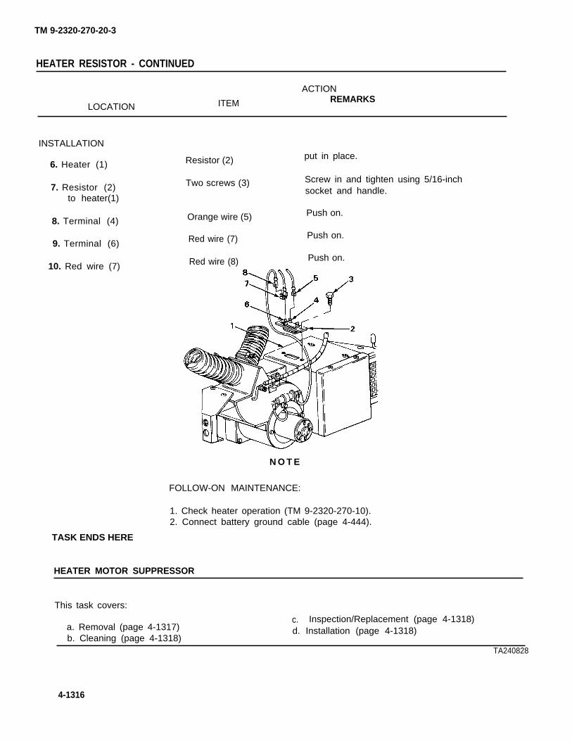
TM 9-2320-270-20-3
HEATER RESISTOR - CONTINUED
ACTION
ITEM REMARKSLOCATION
INSTALLATION
Resistor (2) put in place.6. Heater (1)
7. Resistor (2) Two screws (3) Screw in and tighten using 5/16-inch
to heater(1)socket and handle.
8. Terminal (4) Orange wire (5) Push on.
9. Terminal (6)
10. Red wire (7)
Red wire (7)
Red wire (8)
Push on.
Push on.
N O T E
FOLLOW-ON MAINTENANCE:
1. Check heater operation (TM 9-2320-270-10).2. Connect battery ground cable (page 4-444).
TASK ENDS HERE
HEATER MOTOR SUPPRESSOR
This task covers:
a. Removal (page 4-1317)c. Inspection/Replacement (page 4-1318)
b. Cleaning (page 4-1318)d. Installation (page 4-1318)
TA240828
4-1316

TM 9-2320-270-20-3
HEATER MOTOR SUPPRESSOR - CONTINUED
INITIAL SETUP
Tools
Extension,1l/4-inch drive, 3-inchHandle, ratchet, 1/4-inch driveScrewdriver, flat-tip, 1/4-inchSocket, 1/4-inch, 1/4-inch drive
Materials/Parts
Lockwasher, red wire to right terminalLockwasher, red wire to left terminal
ACTIONLOCATION ITEM REMARKS
Personnel Required
One
Equipment Condition
Battery ground cable disconnected(page 4-444).
REMOVAL
1. Red wire to resistor Screw (3), lock- s.(1) to right washer (4), andterminal (2) wire (1) b.
2. Red wire to motor Screw (7), lock- s.(5) to left washer (8), andterminal (6) wire (5) b.
Using screwdriver, unscrew and takeout.Get rid of Iockwasher (4).
Using screwdriver, unscrew and takeout.Get rid of Iockwasher (8).
3. Bracket (9) to Screw (11), Using 1/4-inch socket, handle, and exten-heater (10) bracket (9), and sion, unscrew and take off.
suppressor (12)
4. Bracket (9) Suppressor (12) Slide out,
TA240829
4-1317

TM 9-2320-270-20-3
HEATER MOTOR SUPPRESSOR - CONTINUED
ACTION
LOCATION ITEM REMARKS
CLEANING
5.
inspection/REPLACEMENT
6.
All parts Clean according to general maintenanceinstructions (page 4-1).
All parts inspect according to general maintenanceinstructions (page 4-1).
INSTALLATION
Suppressor must be installed correctly or it will not work. Flange end must be connectedto resistor wire.
7. Bracket (1)
8. Heater(3)
9. Bracket (1) toheater (3)
Suppressor (2)
Bracket (1)
Screw (4)
Slide in so it is even on both sides.
Put in place and hold.
Screw in and tighten using 1/4-inchsocket, handle, and extension.
10. Screw (5) Red wire to motor Put on.
(6) and newIockwasher (7)
11. Terminal (8) Screw (5) Screw in and tighten using screwdriver.
12. Screw (9) Red wire to resistor Put on.
(10) and newIockwasher(11)
13. Terminal (12) Screw (9) Screw in and tighten using screwdriver.
4-1318
N O T E

TM 9-2320-270-20-3
HEATER MOTOR SUPPRESSOR - CONTINUED
FOLLOW-ON MAINTENANCE:
1. Check heater motor operation (TM 9-2320-270-10).2. Connect battery ground cable (page 4-444).
TASK ENDS HERE
HEATER COOLANT RETURN ELBOW
This task covers:
a. Removal (page 4-1320) c. Inspection/Replacement (page 4-1320)b. Cleaning (page 4-1320) d. Installation (page 4-1321)
INITIAL SETUP
Tools
Knife, pocketPan, drainScrewdriver, flat-tip, 3/16-inchWrench, open-end, 11/16-inchWrench, open-end, 11/8-inch
Materials/Parts
Soap, liquid(item 14, appendix C)
Materials/Parts - Continued
Tape, teflon (item 22, appendix C)
Personnel Required
One
Equipment Condition
Right side of hood open and right hood sidepanel removed (TM 9-2320-270-10).
TA240830
4-1319

TM 9-2320-270-20-3
HEATER COOLANT RETURN ELBOW - CONTINUED
ACTIONLOCATION ITEM REMARKS
REMOVAL
Be careful when removing radiator cap. If engine is hot, escaping steam could burnyou. Using a rag, cover radiator cap to protect your hand. Unscrew cap just enough toallow any built-up steam to escape. When all pressure has been relieved, unscrew capthe rest of the way, and take off of radiator.
1. Radiator(1) Radiator cap (2) am
b.
2.
3. Hose (4) toelbow (5)
Draincock (3)
Clamp (6)
a.b.c.d.
a.b.
N O T E
Slowly unscrew to first stop, pause,and let pressure escape.When all pressure has escaped,unscrew and take off.
Put drain pan underneath.Open and let coolant drain.When coolant stops drainingGet rid of coolant (page 4-1).
Put drain pan underneath.
close.
Using screwdriver, unscrew and slidedown.
it maybe necessary to cut off hose with pocket knife. if hose has to be cut, replacehose.
4. Elbow (5) Hose (4) a. Twist and pull off.b. Get rid of coolant (page 4-1).
5. Reducer(7) Elbow (5) Using 11/8-inch and 11/16-inchwrenches, unscrew and take out.
6. Thermostat Reducer (7) Using 11/8-inch wrench, unscrew and takehousing (8) out.
CLEANING
7. Clean according to general maintenanceinstructions (page 4-1).
All parts
INSPECTION/REPLACEMENT
8. All parts inspect according to general maintenanceinstructions (page 4-1).
WARNING
4-1320

TM 9-2320-270-20-3
HEATER COOLANT RETURN ELBOW - CONTINUED
LOCATIONACTION
ITEM REMARKS
INSTALLATION
9. Thermostathousing (8)
10. Reducer (7)
11. Elbow (5)
12. Hose (4) toelbow (5)
13.
Reducer (7)
Elbow (5)
Hose (4)
Clamp (6)
Cooling system
a.
b.
a.
b.
Wrap threads with teflon tape(page 4-1).Screw in and tighten using 1 1/8-inch wrench.
Wrap threads with teflon tape(page 4-1).Screw in and tighten using 11/16-inchwrench.
Lube elbow (1) lightly with soap and pushon until seated.
Slide into place and using screwdriver,tighten.
Fill (TM 9-2320-270-10).
TA240831
4-1321

HEATER COOLANT RETURN ELBOW - CONTINUED
INSTALLATION – CONTINUED
N O T E
FOLLOW-ON MAINTENANCE:
1. Check for leaks (page 4-1).2. Close right side of hood and install right hood side panel TM 9-2320-270-10).
TASK ENDS HERE
DATA PLATES SECURED WITH BLIND RIVETS
This task covers:
Replacement (page 4-1322)
INITIAL SETUP
ToolsMaterials/Parts
Drill twist, 3/32-inchData pIate (as required)
Drill twist, 1/8-inchBlind rivets, 3/32-inch (as required)
Drill, electric, portableBlind rivets, 1/8-inch (as required)
Hammer, machinist’s ball-peenPunch, drive pin, 3/32-inch
Personnel Required
Punch, drive pin, 1/8-inchRiveter, blind, hand
One
Stamps, metal numbering and lettering(as required)
ACTION
ITEM REMARKSLOCATION
REPLACEMENT
N O T E
Except as noted, steps in this task apply to all data plates secured with blind rivets.Noise emissions data plate is shown.
All data plates secured with blind rivets useplate, which is secured with 3/32-inch rivets,
1. Data plate(1)Four rivets (3)
to door(2)
1/8-inch rivets, except for rustproofing data
a. Using drill and twist, drill off rivetheads (4).
b. Using punch and hammer, tap out.C. Get rid of.
TM9-2320-270-20-3
4-1322

TM 9-2320-270-20-3
DATA PLATES SECURED WITH BLIND RIVETS - CONTINUED
LOCATION ITEMACTION
REMARKS
2. Door(2) Data plate (I) Take off.
3. New data plate (1) Using number stamps and hammer,restamp any numbers.
4. Door(2)
5. Data plate(1)to door(2)
TASK ENDS HERE
New data plate (1)
Four new rivets (3)
Put in place.
Using riveter, put in.
TA240832
4-1323

TM 9-2320-270-20-3
DATA PLATES AND DECALS SECURED WITH ADHESIVE
This task covers:
Replacement (page 4-1224)
INITIAL SETUP
Tools Materials/Parts
Knife, putty Rags, wiping
– Continued
(item 10, appendix C)
Materials/Parts Personnel Required
Data plate or decal (as required) OneNaptha (item 9, appendix C)
ACTIONLOCATION ITEM REMARKS
REPLACEMENT
N O T E
Steps in this task are the same for ail data plates and decals secured with adhesive. Leftdoor warning plate is shown.
1. Door(1) Data plate (2) a. Using putty knife, scrape off.b. Get rid of.
W A R N I N G
Naptha and its fumes are harmful and flammable. Do not smoke or use near open framewhile using. Use only in weii-ventilated area. Naptha can catch fire and fumes canexplode causing serious injury.
Door (1) Using naptha and rags, clean off all ad-hesive.
New data plate (2) a. Peel off paper backing.b. Place on door and smooth out any air
hubbies.
2.
3. Door(1)
4-7324

TM 9-2320-270-20-3
DATA PLATES AND DECALS SECURED WITH ADHESIVE- CONTINUED
TASK ENDS
DATA PLATES SECURED WITH DRIVESCREWS
This task covers:
Replacement (page 4-1326)
INITIAL SETUP
Tools
Chisel, cold-hand, 3/8-inchDrill twist, 1/8-inchDrill, portable electricHammer, machinist’s ball-peen
Materials/Parts
Data Plate (as required)Drivescrew (as required)Tape, pressure sensitive (item 21, appendix C)
Personnel Required
One
TA240833
4-1325

TM 9-2320-270-20-3
DATA PLATES SECURED WITH DRIVESCREWS - CONTINUED
ACTIONLOCATION ITEM REMARKS
REPLACEMENT
N O T E
Steps in this task are the same for all data plates secured with drivescrews. Winchcontrol panel engine shut down plate is shown.
1. Data plate (1) Four drive- s. Using hammer and chisel, cut offto winch control screws (3) drivescrew heads.panel(2) b. Get rid of.
2. Winch control Data plate (1) Take off.panel (2)
3. Winch control New data plate (1) Put on as close as possible topanel (2) location of old data plate, screw holes
should not line up.
4. Winch control a. Put tape on drill twist, same dis-panel (2) tance on twist as length of
drivescrew shank.b. Using new data plate as template and
using drill and twist, drill four holessame length of screws (3).
5. Data plate (1) Four drive-to winch control screws (3)panel (2)
Using hammer, tap in.
TASK ENDS HERE
4-1326
TA240834

TM 9-2320-270-20-3
DATA PLATES SECURED WITH SELF-TAPPING SCREWS
This task covers:
Replacement (page 4-1327)
INITIAL SETUP
Tools Materials/Parts
Hammer, machinist’s ball-peen Data Plate (as required)Screwdriver, cross-tip, number 1 Self-tapping screw (as required)Screwdriver, fiat-tip, 1/4-inchStamps, numbering Personnel Required
One
ACTiONLOCATION ITEM REMARKS
REPLACEMENT
N O T E
Except as noted, steps in this task are the same for all data plates secured with self-tapping screws. The truck cab number plate is shown.
Truck cab serial number plate uses cross tip screws, all others use slotted screws.
1. Data plate (1) Two screws (3)to door(2)
2. Door(2) Data plate (1)
Using screwdriver, unscrew and take out.
Take off.
TA240835
4-1327

TM 9-2320-270-20-3
DATA PLATES SECURED WITH SELF-TAPPING SCREWS - CONTINUED
ACTIONLOCATION ITEM REMARKS
REPLACEMENT – CONTINUED
3. New data plate (1)
4. Door(2)
5. Data plate (1)to door(2)
TASK ENDS HERE
ENGINE DATA PLATE
New data plate (1)
Two screws (3)
Using hammer and numbering stamps,stamp any number stamped on old dataplate.
Put in place and hold.
Screw in and tighten using screwdriver.
This task covers:
Replacement (page 4-1329)
INITIAL SETUP
Tools
Pliers, long-nose
Materials/Parts
Engine data plate
Personnel Required
One
Equipment Condition
Right side of hood open and right hood sidepanel removed (TM 9-2320-270-10). TA240836
4-1328

TM 9-2320-270-20-3
ENGINE DATA PLATE - CONTINUED
LOCATION ITEMACTION
REMARKS
REPLACEMENT
1. Data plate (1) tovalve cover (2)
2. Valve cover (2)
3.
4. Data plate (1) tovalve cover (2)
Three tabs (3)
Data plate (1)
New data plate
Three tabs (3)
FOLLOW-ON MAINTENANCE:(TM 9-2320-270-10).
TASK ENDS HERE
Using pliers, pry up.
Slide out.
Slide in.
Using pliers, push down.
N O T E
Close right side hood and install right hood side panel
TA240837
4-1329
TM 9-2320-270-20-3
INSTRUMENT PANEL NON-ILLUMINATED LABEL ASSEMBLY
This task covers:
Maintenance (page 4-1330)
MAINTENANCEN O T E
Instrument panel label assembly maintenance can be found in Electrical Section,Instrument Panel Label Assembly (page 4-404).
TASK ENDS HERE
INSTRUMENT PANEL ILLUMINATED LABEL ASSEMBLY
This task covers:
Maintenance (page 4-1330)
MAINTENANCE N O T E
Instrument panel illuminated label assembly maintenance can be found in ElectricalSection, Optical Ribbon and Light Source (page 4-563).
TASK ENDS HERESection XIX. GAGES, NONELECTRIC
Page
Air Pressure Gage . . . . . . . . . . . . . . . . . . . . . . . . . . . . . . . . . . . . . . . . . 4-1330
AIR PRESSURE GAGE
This task covers:
a. Removal (page 4-1331) c. Inspection/Replacement (page 4-1332)
b. Cleaning (page 4-1332) d. Installation (page 4-1332)
INITIAL SETUP
Tools
Hammer, plasticPliers, long-nose, roundScrewdriver, flat-tip, 3/8-inchWrench, open-end, 9/16-inch
Materials/Parts
Lockwasher, gage to retainer (two required)Soap, liquid (item 14, appendix C)Tape, teflon (item 22, appendix C)
4-1330

TM 9-2320-270-20-3
AIR PRESSURE GAGE - CONTINUED
INITIAL SETUP - CONTINUED
Personnel Required Equipment Condition
One Instrument panel open (page 4-244).
LOCATION ITEMACTION
REMARKS
REMOVAL
Make sure all pressure is drained from air system before disconnecting air lines. Partsunder pressure can, when removed, fly off with great force causing injury to personnel.
WARNING
1. Air system Drain (TM 9-2320-270-10).
2. Gage (1)
3. Adapter (3)
Lamp socket (2)
Air line 41 (4)
4. Air line 41 (4) or Insert (5)adapter (3)
Pull out.
Using 9/16-inch wrench, unscrew andpull out.
Using pliers, pull out.
5. Adapter (6) Airline 610 (7) Using 9/16-inch wrench, unscrew andpull out.
6. Air line 610 (7) or Insert (8)adapter (6)
Using pliers, pull out.
4-1331

TM 9-2320-270-20-3
AIR PRESSURE GAGE - CONTINUED
ACTIONLOCATION ITEM REMARKS
REMOVAL – CONTINUED
7. Two nipples (1)
8. Gage (4) toretainer (5)
9. Gage (4) toinstrument panel (8)
10. Instrument panel (8)
CLEANING
11.
lNSPECTION/REPLACEMENT
12.
INSTALLATION
13. Instrument panel (8)
14. Gage (4) to instru-ment panel (8)
15. Retainer (5) togage (4)
16. Two nipples (1)
17. Adapter (3)
18.
19. Adapter (2)
4-1332
Two adapters (2)and (3)
Two nuts (6) andIockwashers (7)
Retainer (5)
Gage (4)
All parts
All parts
Gage (4)
Retainer (5)
Two new Iockwashers(7) and nuts (6)
Two adapters (2)and (3)
Insert (9)
Air line 610 (10)
Insert (11)
Using 9/16-inch wrench, unscrew and takeoff.
a. Using 9/16-inch wrench, unscrew andtake off.
b. Get rid of Iockwashers (7).
Take off.
Take out.
Clean according to general maintenanceinstructions (page 4-1).
Inspect according to general maintenanceinstructions (page 4-1).
Put in place.
Put on.
Screw on and tighten using 9/16-inchwrench.
a. Wrap nipple threads with teflon tape(page 4-1).
b. Screw on and tighten using 9/16-inchwrench.
Push in and using plastic hammer, seat.
a. Lube end lightly with soap and push inuntil seated.
b. Screw on and tighten using 9/16-inchwrench.
Push in and using plastic hammer, seat.

TM 9-2320-270-20-3
AIR PRESSURE GAGE - CONTINUED
LOCATION ITEMACTION
REMARKS
20. Air line 41 (12) a. Lube end lightly with soap and push inuntil seated.
b. Screw on and tighten using 9/16-inchwrench.
21. Gage (4)
22.
23.
Lamp socket (13)
Gage (4)
Gage connections
Push in.
a.
b.
a.b.
Start engine and check operation(TM 9-2320-270-10).Charge air system to normal pressure(TM 9-2320-270-10).
Check for leaks (page 4-1).Shut down engine(TM 9-2320-270-10).
TASK ENDS HERE
TA240839
4-1333/(4-1334 blank)


TM 9-2320-270-20-3
APPENDIX A
REFERENCES
Page Page
Forms . . . . . . . . . . . . . . . . . . . . . . . . . . . . . . . . . . . . . . . . . . . . . . . . . . . . . . . . . . . . A-1 Scope . . . . . . . . . . . . . . . . . . . . . . . . . . . . . . . . . . . . . . . . . . . . . . . . . . . . . . . . . . . A-1Miscellaneous Publications . . . . . . . . . . . . . . . . . . . . . . . . A-2 Technical Bulletins . . . . . . . . . . . . . . . . . . . . . . . . . . . . . . . . . . . . . A-1Publication Indexes . . . . . . . . . . . . . . . . . . . . . . . . . . . . . . . . . . . . . . A-1 Technical Manuals . . . . . . . . . . . . . . . . . . . . . . . . . . . . . . . . . . . . . A-1
SCOPE
This appendix lists all forms, field manuals, technical manuals, and miscellaneous publicationsreferenced in this manual.
PUBLICATION INDEXES
The following indexes should be consulted frequently for latest changes or revisions and for newpublications relating to material covered in this technical manual.
Consolidated Index of Army Publications . . . . . . . . . . . . . . . . . . . . . . . . . . . . . . . . . . . . . . . . . . . . . . . . . . . . . . . . . . . . . . . . . . . DA PAM 310-1US Army Equipment Index of Modification Work Orders . . . . . . . . . . . . . . . . . . . . . . . . . . . . . . . . . . . . . . . . . . . DA PAM 750-10
FORMS
Refer to DA PAM 738-750. The Army Maintenance Management Systems (TAMMS), for instructionson the use of maintenance forms pertaining to this equipment.
TECHNICAL MANUALS
Cooling Systems: Tactical Vehicles . . . . . . . . . . . . . . . . . . . . . . . . . . . . . . . . . . . . . . . . . . . . . . . . . . . . . . . . . . . . . . . . . . . . . . . . . . . . .Destruction of Army Materiel to Prevent Enemy Use . . . . . . . . . . . . . . . . . . . . . . . . . . . . . . . . . . . . . . . . . . . . . . . . . .Materials Used for Cleaning, Preserving, Abrading and Cementing
Ordnance Materiel and Related Materials Including Chemicals . . . . . . . . . . . . . . . . . . . . . . . . . . .Inspection, Care, and Maintenance of Antifriction Bearings . . . . . . . . . . . . . . . . . . . . . . . . . . . . . . . . . . . . .Operator and Organizational Maintenance Manual for Lead-Acid
Storage Batteries . . . . . . . . . . . . . . . . . . . . . . . . . . . . . . . . . . . . . . . . . . . . . . . . . . . . . . . . . . . . . . . . . . . . . . . . . . . . . . . . . . . . . . . . . . . . . . . . . . . . . . .Operator’s Manual, Truck, Tractor, Commerical Heavy Equipment
Transporter (C-HET) . . . . . . . . . . . . . . . . . . . . . . . . . . . . . . . . . . . . . . . . . . . . . . . . . . . . . . . . . . . . . . . . . . . . . . . . . . . . . . . . . . . . . . . . . . . . . . . . . . .Operator’s Manual: Welding Theory and Application . . . . . . . . . . . . . . . . . . . . . . . . . . . . . . . . . . . . . . . . . . . . . . . . .Organizational Care, Maintenance Care, Maintenance and Repair of
Pneumatic Tires and Inner Tubes . . . . . . . . . . . . . . . . . . . . . . . . . . . . . . . . . . . . . . . . . . . . . . . . . . . . . . . . . . . . . . . . . . . . . . . . . . . . .Organizational Maintenance Repair Parts and Special Tools List . . . . . . . . . . . . . . . . . . . . . . . . . . . .
TM 750-254TM 750-244-6
TM 9-247TM 9-214
TM 9-6140-200-14
TM 9-2320-270-10TM 9-237
TM 9-2610-200-24TM 9-2320-270-20P
TECHNICAL BULLETINS
Elimination of Combustibles from Interiors of Metal or PlasticGasoline and Diesel Fuel Tanks . . . . . . . . . . . . . . . . . . . . . . . . . . . . . . . . . . . . . . . . . . . . . . . . . . . . . . . . . . . . . . . . . . . . . . . . . . . . . . . TB 750-047
. Equipment Improvement Report and Maintenance Digest . . . . . . . . . . . . . . . . . . . . . . . . . . . . . . . . . . . . . . . . TB 43-0001-40Rustproofing Procedures . . . . . . . . . . . . . . . . . . . . . . . . . . . . . . . . . . . . . . . . . . . . . . . . . . . . . . . . . . . . . . . . . . . . . . . . . . . . . . . . . . . . . . . . . . . . . . TB 43-0213Use of Antifreeze Solutions and Cleaning Compounds in Engine
Cooling Systems . . . . . . . . . . . . . . . . . . . . . . . . . . . . . . . . . . . . . . . . . . . . . . . . . . . . . . . . . . . . . . . . . . . . . . . . . . . . . . . . . . . . . . . . . . . . . . . . . . . . . . . . TB 750-651
A-1

TM 9-2320-270-20-3
TECHNICAL BULLETINS - CONTINUED
Warranty Procedures for M911, Truck, Tractor, Commercial HeavyEquipment Transporter . . . . . . . . . . . . . . . . . . . . . . . . . . . . . . . . . . . . . . . . . . . . . . . . . . . . . . . . . . . . . . . . . . . . . . . . . . . . . . . . . . . . . . . . . . . . . TB 9-2300-295-
15/15
MISCELLANEOUS PUBLICATIONS
Lubrication Order for Truck, Tractor, Commercial Heavy EquipmentTransporter (C-H ET) . . . . . . . . . . . . . . . . . . . . . . . . . . . . . . . . . . . . . . . . . . . . . . . . . . . . . . . . . . . . . . . . . . . . . . . . . . . . . . . . . . . . . . . . . . . . . . . . . . . LO 9-2320-270-12
A-2

TM 9-2320-270-20-3
APPENDIX B
MAINTENANCE ALLOCATION CHART
Page
Section 1.Section Il.Section III.Section IV.
Introduction . . . . . . . . . . . . . . . . . . . . . . . . . . . . . . . . . . . . . . . . . . . . . . . . . . . . . . . . . . . . . . . . . . . . . . . . . . . . . . . . . . . . . . . . . . . . . . B-1Maintenance Allocation Chart . . . . . . . . . . . . . . . . . . . . . . . . . . . . . . . . . . . . . . . . . . . . . . . . . . . . . . . . . . . . . . . . B-5Tool and Test Equipment Requirements . . . . . . . . . . . . . . . . . . . . . . . . . . . . . . . . . . . . . . . . . . . . . . . . B-22Remarks . . . . . . . . . . . . . . . . . . . . . . . . . . . . . . . . . . . . . . . . . . . . . . . . . . . . . . . . . . . . . . . . . . . . . . . . . . . . . . . . . . . . . . . . . . . . . . . . . . . . B-30
Section I INTRODUCTION
Page Page
Explanation of Columns in General . . . . . . . . . . . . . . . . . . . . . . . . . . . . . . . . . . . . . . . . . . . . . . . . . . . . . . . . B-1Remarks, Section IV . . . . . . . . . . . . . . . . . . . . . . . . . . . . . . . . . . . B-4 Maintenance Functions . . . . . . . . . . . . . . . . . . . . . . . . . . . . . B-1
Explanation of Columns inthe MAC, Section II . . . . . . . . . . . . . . . . . . . . . . . . . . . . . . . . . . . . . B-3
Explanation of Columns inTool and Test EquipmentRequirements, Section III . . . . . . . . . . . . . . . . . . . . . . . . . . B-4
This section provides a general explanation of all maintenance and repair functions authorized atvarious maintenance categories.
The Maintenance Allocation Chart (MAC) in Section II designates overall authority and responsibilityfor the performance of maintenance functions on the identified end item or component. Theapplication of the maintenance functions to the end item or component will be consistent with thecapacities and capabilities of the designated maintenance categories.
Section Ill lists the tools and test equipment (both special tools and common tool sets) required foreach maintenance function as referenced from Section Il.
Section IV contains supplemental instructions and explanatory notes for a particular maintenancefunction.
MAINTENANCE FUNCTIONS
Maintenance functions will be limited to and defined as follows (except for ammunition MAC1):
Inspect. To determine the serviceability of an item by comparing its physical, mechanical, and/orelectrical characteristics with established standards through examination (e.g., by sight, sound, orfeel).
1Exception is authorized for ammunition MAC to permit the redesignation/redifinition of maintenancefunction headings to more adequately identify ammunition maintenance functions. The headingdesignations and definitions will be included in the appropriate technical manual for each category ofammunition.
B-1

TM 9-2320-270-20-3
MAINTENANCE FUNCTIONS - CONTINUED
Test. To verify serviceability by measuring the mechanical, pneumatic, hydraulic, or electricalcharacteristics of an item and comparing those characteristics with prescribed standards.
Service. Operations required periodically to keep an item in proper operating condition, i.e., toclean (includes decontaminate when required), to preserve, to drain, to paint, or to replenish fuel,lubricants, chemical fluids, or gases.
Adjust. To maintain or regulate, within prescribed limits, by bringing into proper or exact position, orby setting the operating characteristics to specified parameters.
Aline. To adjust specified variable elements of an item to bring about optimum or desiredperformance.
Calibrate. To determine and cause corrections to be made or to be adjusted on instruments or test,measuring, and diagnostic equipment used in precision measurement. Consists of comparisons oftwo instruments, one of which is a certified standard of known accuracy, to detect and adjust anydiscrepancy in the accuracy of the instrument being compared.
Remove/lnstall To remove and install the same item when required to perform service or othermaintenance functions. Install may be the act of emplacing, seating, or fixing into position a spare,repair part, or module (component or assembly) in a manner to allow the proper functioning ofequipment or a system.
Replace. To remove an unserviceable item and install a serviceable counterpart in its place.“Replace” is authorized by the MAC and is shown as the 3rd position code of the SMR code.
Repair. The application of maintenance services2, including fault location/troubleshooting3,removal/installation, and disassembly/assembly4 procedures, and maintenance actions5 to identifytroubles and restore serviceability to an item by correcting specific damage, fault, malfunction, orfailure in part, subassembly, module (component or assembly), end item, or system.
Overhaul. That maintenance effort (service/action) prescribed to restore an item to a completelyserviceable/operational condition as required by maintenance standards in appropriate technicalpublications (i.e., DMWR). Overhaul is normally the highest degree of maintenance performed bythe Army. Overhaul does not normally return an item to a like new condition.
2Services - inspect, test, service, adjust, aline, calibrate, and/or replace.3Fault location/troubleshoot - The process of investigating and detecting the cause of equipmentmalfunction; the act of isolating a fault within a system or unit under test (UUT).4Disassembly/assembly - encompasses the step-by-step taking apart (or breakdown) of aspare/functional group coded item to the level of its least componency identified as maintenancesignificant (i.e., assigned an SMR code) for the category of maintenance under consideration.5Actions – welding, grinding, riveting, straightening, facing, remachinery and/or resurfacing.
B-2

TM 9-2320-270-20-3
MAINTENANCE FUNCTIONS - CONTINUED
Rebuild. Consists of those services/actions necessary for the restoration of unserviceable equipmentto a Iike new condition in accordance with original manufacturing standards. Rebuild is the highestdegree of materiel maintenance applied to Army equipment. The rebuild operation includes the act ofreturning to zero those age measurements (hours/miles. etc.) considered in classifying Armyequipment/components.
EXPLANATION OF COLUMNS IN THE MAC, SECTION II
Column 1, Group Number. Column 1 lists functional group code numbers, the purpose of which is toidentify maintenance significant components, assemblies, subassemblies, and modules of the nexthigher assembly. End item group number shall be “00”.
Column 2, Component/Assembly. Column 2 contains the names of components, assemblies,subassemblies, and modules for which maintenance is authorized.
Column 3, Maintenance Function. Column 3 lists the functions to be performed on the item listed inColumn 2. (For detailed explanation of these functions, see Maintenance Functions, page B-l).
Column 4, Maintenance Category. Column 4 specifies, by the listing of a work time figure in theappropriate subcolumn(s), the category of maintenance authorized to perform the function listed inColumn 3. This figure represents the active time required to perform that maintenance function at theindicated category of maintenance. If the number or complexity of the tasks within the listedmaintenance function vary at different maintenance categories, appropriate work time figures will beshown for each category. The work time figure represents the average time required to restore an item(assembly, subassembly, component, module, end item, or system) to a serviceable conditionunder typical field operating conditions. This time includes preparation time (including any necessarydisassembly/assembly time), troubleshooting/fault location time, and quality assurance/qualitycontrol time in addition to the time required to perform the specific tasks identified for the maintenancefunctions authorized in the maintenance allocation chart. The symbol designations for the variousmaintenance categories are as follows:
C - Operator/CrewO - Organizational MaintenanceF - Direct Support MaintenanceH - General Support MaintenanceL - Specialized Repair Activity (SRA) D - Depot Maintenance
This maintenance category is not included in Section II, Column 4, of the Maintenance AllocationChart. To Identify functions to this category of maintenance, enter a work time figure in the “H” columnof Section 11,, Column 4, and use an associated reference code in the Remarks column, Column 6.Key the code to Section IV, Remarks, and explain the SRA complete repair application there. Theexplanatory remark(s) shall reference the specific Repair Parts and Special Tools List (RPSTL) TM.which contains additional SRA criteria and the authorized spare/repair parts.
B-3

TM 9-2320-270-20-3
EXPLANATION OF COLUMNS IN THE MAC, SECTION II - CONTINUED
Column 5, Tools and Equipment. Column 5 specifies, by code, those common tools sets (notindividual tools) and special tooIs, TMDE, and support equipment required to perform the designated function.
Column 6, Remarks. This column shall, when applicable, contain a letter code, in alphabetic order,which shall be keyed to the remarks contained in Section IV.
EXPLANATION OF COLUMNS IN TOOLS AND TEST EQUIPMENT REQUIREMENTS, SECTION Ill
Column 1, Reference Code. The tool and test equipment reference code correlates with a code usedin the MAC, Section II, Column 5,
Column 2, Maintenance Category. The lowest category of maintenance authorized to use the tool ortest equipment.
Column 3, Nomenclature. Name or identification of the tool or test equipment.
Column 4, National Stock Number. The National Stock Number of the tool or test equipment.
Column 5, Tool Number. The manufacturer’s part number.
EXPLANATION OF COLUMNS IN REMARKS, SECTION IV
Column 1, Reference Code. The code recorded in Column 6, Section Il.
Column 2, Remarks. This column lists information pertinent to the maintenance function beingperformed as indicated in the MAC, Section Il.
B-4

TM 9-2320-270-20-3
Section Il. MAINTENANCE ALLOCATION CHART
B-5

TM 9-2320-270-20--3
MAINTENANCE ALLOCATION CHART - CONTINUED
B-6

TM 9-2320-270-20-3
MAINTENANCE ALLOCATION CHART - CONTINUED
B-7

TM 9-2320-270-20-3
MAINTENANCE ALLOCATION CHART - CONTINUED
B-8

TM 9-2320-270-20-3
MAINTENANCE ALLOCATION CHART - CONTINUED
B-9

TM 9-2320-270-20-3
MAINTENANCE ALLOCATION CHART - CONTINUED
B-10

TM 9-2320-270-20-3
MAINTENANCE ALLOCATION CHART - CONTINUED
B-11

TM 9-2320-270-20-3
MAINTENANCE ALLOCATION CHART - CONTINUED
B-12

TM 9-2320-270-20-3
MAINTENANCE ALLOCATION CHART - CONTINUED
B-13

TM 9-2320-270-20-3
MAINTENANCE ALLOCATION CHART - CONTINUED
B-14

TM 9-2320-27020-3
MAINTENANCE ALLOCATION CHART - CONTINUED
B-15

TM 9-2320-270-20-3
MAINTENANCE ALLOCATION CHART - CONTINUED
B-16

TM 9-2320-270-20-3
MAINTENANCE ALLOCATION CHART - CONTINUED
B-17

MAINTENANCE ALLOCATION CHART - CONTINUED
)
B-18

TM 9-2320-270-20-3
MAINTENANCE ALLOCATION CHART - CONTINUED
B-19
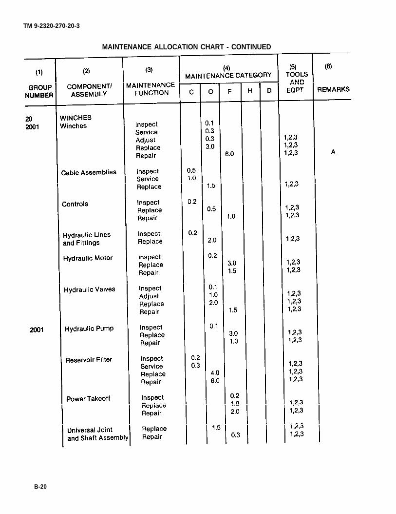
TM 9-2320-270-20-3
MAINTENANCE ALLOCATION CHART - CONTINUED
B-20

TM 9-2320-270-20-3
MAINTENANCE ALLOCATION CHART - CONTINUED
B-21

(1) (2) (3)REFERENCE LEVEL
CODE MAINTENANCE NOMENCLATURE
1
2
3
4
5
6
7
8
9
10
O
O
O
F
F
F
F
F
F
F
(4)NATIONAL
STOCK NUMBER
TM 9-2320-270-20-3
Section III. TOOL AND TEST EQUIPMENT REQUIREMENTS
(5)TOOL
NUMBER
TOOL SETS:Automotive Maintenance
and Repair
General MechanicsAutomotive Tool Kit
Number 1 Common Organi-zational MaintenanceAutomotive RepairShop Equipment
5180-00-177-7033
4910-00-754-0654
Number 1 SupplementalAutomotive MaintenanceSet
4910-00-754-0653
CHASSIS TOOLS:Engine
Collet, Valve Seat (usew/J2347415 puller)
5120-01-048-1379 J23479-13
Fixture, Cam FollowerService
2815-00-705-9278 J5840-01
Fixture, Lifting Cylin-der Head
4810-00-456-7620 J22062-01
Fixture, Valve HoldingBridge
4940-01-025-0424 J21772
Gage, Throttle DelayCylinder (0.520)
J24873
Gage, Throttle DelayCylinder (0.570)
5120-01-048-2200 J25559
installer, Camshaft GearConsisting of:
Driver
5120-00-473-7456 J1903
5120-01-048-1381 J1903-1
Pilot 5120-01-048-1380 J1903-2
B-22

TM 9-2320-270-20-3
TOOL AND TEST EQUIPMENT REQUIREMENTS - CONTINUED
(1) (2)REFERENCE LEVEL
CODE MAINTENANCE
11
12
13
14
15
16
17
F
F
F
F
F
F
18
19
20
F
F
F
O
(3)
NOMENCLATURE
(4) (5)NATIONAL TOOL
STOCK NUMBER NUMBER
Installer, CrankshaftFront Oil Seal
Installer, CrankshaftOil Seal Sleeve (usew/J. 8092 handle andw/J9727-2 guide)
Installer/Remover, AfterCooler Water inletAdapter Consisting of:
Body Assembly
Extension
Plate, Stabilizer
Installer, ThermostatHousing Seal (usew/J-7079-2 handle)
Installer, Valve BridgeGuide
Installer, Valve Guide
Installer, Valve SeatInsert
Installer, Water Nozzle
Installer, Water PumpDrive Gear
Installer, Water PumpOil Seal
5120-00-936-4377 J9783
5120-00-254-5021 J4194-01
5120-01-048-2180 J25275
5120-01-048-2181 J25275-1
5120-01-048-2154 J25275-3
5120-01-048-2182 J25275-2
5120-00-977-5579 J8550
5120-00-999-8616 J7482
5120-00-999-8617 J21520
5120-01-048-3118 J24357
5120-01-048-3119
5120-01-033-8902
J24857
J25257
5120-00-937-7267 J8501
B-23

TM 9-2320-270-20-3
TOOL AND TEST EQUIPMENT REQUIREMENTS - CONTINUED
(2)LEVEL
MAlNTENANCE
(3)
NOMENCLATURE
(4)NATIONAL
STOCK NUMBER
CHASSIS TOOLS:Engine (Cont)
F Kit, Engine TuneupConsisting of:
Case, Carrying
Gage, FeelerGovernor (0.0015)
5120-01-048-7085
Gage, Governor Gap(0.170)
5120-00-972-0468
Gage, Governor Gap(0.200)
5120-01-048-6532
Gage, Injector Timing(1.460)
5220-00-387-9581
Gage, Injector Timing(1.470)
5120-01-048-3116
Gage, Injector Timing(1.484)
5120-00-474-6400
Gage, Throttle DelayChecking (0.454)
Wrench, Fuel Line Nut
5120-00-538-8465
5120-00-019-5232
Wrench, Open-End3/8 x 7/16 in.
Wrench Set, Push RodAdjusting
Leak Detector SetConsisting of:
Pump, Vacuum
5120-00-132-2109
F
O
Cup, Vacuum
Puller, Tachometer Shaft 5120-01-048-3117
(1)REFERENCE
CODE
21
22
23
(5)TOOL
NUMBER
J24790
J24790-1
J23185
J5407
J23478
J1853
J24236
J1242
J23190
J8932-01
J5345-10
J21100-02
J23987-01
J23987
J23987-2
J24730
B-24

TM 9-2320-270-20-3
TOOL AND TEST EQUIPMENT REQUIREMENTS - CONTINUED
(1) (2)REFERENCE LEVEL
CODE MAINTENANCE
24
25
26 F
27
28
29
30
31
32
33
34
F
F
F
F
F
F
F
F
F
H
(3)
NOMENCLATURE
(4) (5)NATIONAL TOOL
STOCK NUMBER NUMBER
Reamer, Injector Body 5110-00-937-7628
Remover, Camshaft Gearand Water Pump Pulley(use w/J24420 bar)
Remover, Seal and DustShield
Remover, Valve Guide
Remover, Valve GuideBridge Consisting of:
5120-00-733-8880 J6569
5120-00-999-8614 J7091-01
Body
Sleeve, Long
Sleeve, Short
Washer
5120-01-048-3121
5120-01-048-3120
5120-01-048-1384
5120-01-048-1383
Remover, Water Pump Seal
Retainer Nut Wrench,High Speed
5120-00-627-9311
Setting Master Gage Set(use w/J5347-01 gage)
5120-01-367-7378 J23059-01
Stud Set, CrankshaftRear Oil Seal Expander(Use w/J4239 Expanderand w/J8092 handle)
5120-01-048-2155 J25002
Tool, Blower Drive ShaftAliner
5120-01-048-3122 J24619
Tool, Piston PinRetainer
5120-00-127-7757 J23762
J21089
J9732
J24171
J7091-5
J7091-2
J7091-4
J7091-3
J22150-01
J 1652-01
B-25

TM 9-2320-270-20-3
TOOL AND TEST EQUIPMENT REQUIREMENTS - CONTINUED
(1) (2)REFERENCE LEVEL
CODE MAINTENANCE
(3)
NOMENCLATURE
(4) (5)NATIONAL TOOL
STOCK NUMBER NUMBER
35
CHASSIS TOOLS:Engine (Cont)
F Tool Set, Blower ServiceConsisting of:
5120-00-936-4376 J6270-2
Adapter, Remover,Blower Seal RingCarrier
5120-01-048-1387 J6270-2
Installer, BlowerBearing and Seal
5120-00-070-1016 J6270-4
Puller, Blower Gear,End Plate, and SealRing Carrier (2 ea)
5120-00-070-1014 J6270-1
Remover, BlowerBearing and Seal
5120-01-048-1388 J6270-3
Screw
Swivel
36 F Tool Set, Fuel PumpConsisting of:
5120-01-048-1389 J6270-21
5120-01-048-1390 J6270-22
5120-00-785-1001 J1508-3
Adapter
Handle, Oil SealInstaller
5120-00-970-9031 J1508-9
5120-00-970-9030 J1508-8
Holder, Fuel Pump
Remover, Oil Seal
37 F Tool Set, Injector TubeReconditioningConsisting of:
5120-00-494-1770 J1508-10
5120-01-048-1385 J1508-13
2910-00-146-9619 J22525
Box and InstructionAssembly
J5286-25
Installer, Body 4940-00-711-1918 J5286-4
B-26

TM 9-2320-270-20-3
(1)REFERENCE
CODE
37(Cont)
38
(2)LEVEL
MAINTENANCE
F
(4)NATIONAL
STOCK NUMBER
TOOL AND TEST EQUIPMENT REQUIREMENTS - CONTINUED
(3)
NOMENCLATURE
(5)TOOL
NUMBER
Installer, FlaringDie
4940-00-071-1920 J5286-6
Installer, Pilot
Pilot Reamer
Refinisher, Tube Tip
Reamer, FirstOperation
4940-00-711-1919 J5286-5
5110-01-048-2199 J22525-3
5120-00-785-1017 J5286-8
5120-01-048-2198 J22525-1
Reamer, SecondOperation
Vise and Rack Set,Injector FreenessTesterConsisting of:
5110-00-294-4606 K5286-9
4910-00-950-3119 J22396
Adapter Disk
Base
Block, Support
Fixture, InjectorAssembly
Handle Assembly
O-Ring
Plate, Base
Rack, FreenessTester
Screw Assembly
Stop Tab
J22396-9
J22396-24
J22396-4
J22396-1
5330-01-049-1212
J22396-5
J22396-23
J22396-14
J22396-2
J22396-8
J22396-21
B-27

TM 9-2320-270-20-3
(1) (2)REFERENCE LEVEL
CODE MAINTENANCE
39
40
41
42
43
44
45
46 O
TOOL AND TEST EQUIPMENT REQUIREMENTS - CONTINUED
F
F
F
F
F
O
F
NOMENCLATURE
CHASSIS TOOLS:Fifth Wheel
Adapter, Fifth WheelLock Tester
Tester, Fifth WheelLock
CHASSIS TOOLS:Suspension
Service Set, EqualizingBeam Center, TandemSuspension
Tool, Axle Ball TrunnionFront Axle
Tooling Set, EqualizingBeam End, TandemSuspension
Wrench, Bearing Nut(Front Axle) Wheel
Wrench, Torque Multi-plier Set Consistingof:
Adapter, 3/4-inch
Male, 1/12-inchFemale Adapter
3/4-inch Male,1-inch FemaleWrench, Multiplier
Wrench, Wheel BearingNut (Tandem Axle)
(3) (4) (5)NATIONAL TOOL
STOCK NUMBER NUMBER
5120-01-048-1391
5180-00-706-5578
1TL42
1TL41
1TL32
1TL3
1TL31
1048TR
J6985
J6985-2
J6985-3
J6985-1
5EX217
B-28

TM 9-2320-270-20-3
TOOL AND TEST EQUIPMENT REQUIREMENTS - CONTINUED
(1) (2)REFERENCE LEVEL
CODE MAINTENANCE
47
48
49
50
51
52
53
54
55
H
F
F
H
H
H
H
H
H
(3)
NOMENCLATURE
CHASSIS TOOLS:Transfer Case
wrench, Spanner, Trans-fer Case Differential
CHASSIS TOOLS:Transmission Auxiliary
Puller, Front CounterShaft Bearing Aux-iliary Transmission
Wrench, Input Yoke (Aux-iliary Transmission)
CHASSIS TOOLS:Transmission Main
Compressor, MainPressure Regulator andLockup Valve Spring
Compressor Set, ClutchSpring Consisting of:
Bar and Stud Assembly
Compressor, Forwardand Fourth ClutchSpring
Compressor, Low andFirst Clutch Spring
Gage, Clutch Pack(0.060-0.120)
Gage, Clutch Pack(0.80-0.120)
Gage, Clutch Pack(0.095-0.145)
Gage, Clutch Pack(0.128-0.208)
(4) (5)NATIONAL TOOL
STOCK NUMBER NUMBER
5120-01-148-8749 1TL35
5180-00-706-5578 1TL37
5120-01-048-2160 J24219
5120-01-048-3129 J24204
5120-01-048-2150 J24204-2
5120-01-048-2159 J24204-3
5120-01-048-3130 J24204-1
5120-01-048-2162 J24193
5120-01-048-2161 J24192
5210-01-048-5283 J24194
5120-01-048-2163 J26421
1TL33
B-29

TM 9-2320-270-20-3
TOOL AND TEST EQUIPMENT REQUIREMENTS - CONTINUED
(1) (2)REFERENCE LEVEL
CODE MAINTENANCE
56
57
59
60
H
H
H
H
H
(3)
NOMENCLATURE
(4) (5)NATIONAL TOOL
STOCK NUMBER NUMBER
CHASSIS TOOLS:Transmission Main(Cont)
Installer and Stake SetConsisting of:
5120-01-048-3124 J24200
Stake 5120-01-048-3125
Pilot 5120-01-048-3126
installer, Valve GuidePin
Protector, Clutch PistonInner Seal
5120-01-048-2157 J24216-01
Protector, Low and FirstClutch Piston InnerSeal
5120-01-046-2156 J24210
Remover, Valve Pin (Usew/J6125-1 hammer)
Tool, Valve RingAdjusting
J24200-1
J24200-2
J24458
J24412-2
J24314
Section IV. REMARKS
REFERENCECODE
A
REMARKS
All repair and/or replacement of parts performed by organizational mainte-nance is limited to authorized items listed in TM 9-2320-270-20P.
B-30

TM 9-2320-270-20-3
APPENDIX C
EXPENDABLE SUPPLIES AND MATERIALS LIST
Page
Section 1. Introduction . . . . . . . . . . . . . . . . . . . . . . . . . . . . . . . . . . . . . . . . . . . . . . . . . . . . . . . . . . . . . . . . . . . . . . . . . . . . . . . . . . . . . . . . . . . . . . . . . . . . . . . C-1Section Il. Expendable Supplies and Materials List . . . . . . . . . . . . . . . . . . . . . . . . . . . . . . . . . . . . . . . . . . . . . . . . . . . . . . . . . C-2
Section L INTRODUCTION
Page Page
Explanation of Columns . . . . . . . . . . . . . . . . . . . . . . . . . . . . . . C-1 Scope . . . . . . . . . . . . . . . . . . . . . . . . . . . . . . . . . . . . . . . . . . . . . . . . . . . . . . . . . . . . . C-1
SCOPE
This appendix lists expendable supplies and materials you will need to operate and maintain the M911truck. These items are authorized to you by CTA 50-970, Expendable/Durable items (except Medical,Class V, Repair Parts, and Heraldic items).
EXPLANATION OF COLUMNS
Column 1, item Number. This number is assigned to the entry in the listing and is referenced in thenarrative instructions to identify the material (e.g., “Solvent, cleaning (item 16, appendix C)”).
Column 2, Level. This column identifies the lowest level of maintenance that requires the listed item.
C - Operator/Crewo - Organizational MaintenanceF – Direct Support MaintenanceH - General Support Maintenance
Column 3, National Stock Number. This is the national stock number assigned to the item, use it torequest or requisition the item.
Column 4, Description. indicates the federal item name and, if required, a description to identify theitem. The last line for each item indicates the Federal Supply Code for Manufacturer (FSCM) inparenthesis followed by the part number.
Column 5, Unit of Measure (U/M). Indicates the measure used in performing the actual maintenancefunction. This measure is expressed by a two-character alphabetical abbreviation (e.g., ea, in.,pr). if the unit of measure differs from the unit of issue, requisition the lowest unit of issue that willsatisfy your requirements.
C-1

TM 9-2320-270-20-3
Section II. EXPENDABLE SUPPLIES AND MATERIALS LIST
(2)
LEVEL
(3) (4)NATIONAL STOCK
NUMBER DESCRIPTION (FSCM)
O 8040-00-225-4548 Adhesive, Sealant (Glue):12-ounce (355-ml) can(01139) RTV102
O 8040-01-038-5043 Cement, Gasket:8-ounce (237-ml) can(11083) 5M2471
O 8030-00-220-6973 Cement, Rubber-to-Metal
O 6850-00-319-0834 Cleaning Compound, Solvent(Electrical Parts)(Trichlorotrifluoroethane):11-pound (4.99-kg) bottle(81349) (MIL-C-81302)
O 5350-00-221-0872 Cloth, Abrasive (Crocus):50-sheet package(58536) A-A-1206
O Compound, Insulating
O 3439-00-255-9935 Flux, Soldering (Rosin Base):(81348) OF506
O 5970-00-815-1295 Insulation, Sleeving (ShrinkableTubing):(81349) MIL-I-23053/5
O 6810-00-238-8119 Naptha
O 7920-00-205-1711 Rags, Wiping:50-pound (22.7-kg) bale(58536) A-A-531
O 4020-00-968-1357 Rope, Nylon
O 5350-00-598-5537 Sandpaper, Abrasive: Fine grit(58536) A-A-1202
O 5350-00-598-5539 Sandpaper, Abrasive: Medium grit(58536) A-A-1202
(1)ITEM
NUMBER
1
2
3
4
5
6
7
8
9
10
11
12
13
(5)
U/M
oz
oz
oz
lb
sh
lb
lb
ft
gl
ea
yd
sh
sh
C-2

TM 9-2320-270-20-3
EXPENDABLE SUPPLIES AND MATERIALS LIST - CONTINUED
(2)
LEVEL
(3) (4)NATIONAL STOCK
NUMBER DESCRIPTION (FSCM)
C
O
CO
C
O
O
O
O
O
O
O
7930-00-985-6911 Soap, Liquid, Detergent,General Purpose:5-gallon (-18.93-liter) can(81349) MIL-D-16791
3349-01-007-5491 Solder, Tin Alloy (Rosin Core):(81348) QQ-S-571
Solvent, Drycleaning (SD):(81348) P-D-680
6850-00-264-90386850-00-285-8012
4020-00-233-5987
5-gallon (18.93-liter) can55-gallon (208-liter) drum
String, Twine, Cotton:(81349)
9905-00-537-8954 Tags, Marking:(81349) MIL-T-12755
5640-00-103-2254 Tape, Duct: 60-Yard (54-m) Roll(07124) C-519
5970-00-543-1154 Tape, Electrical, Vinyl:(81349) MIL-I-15126
7510-00-283-0612 Tape, Pressure Sensitive:Adhesive, l-inch wide(58536) A-A-113
8030-00-889-3534 Tape, Teflon, Antiseizing:260-inch (6.41-m) Roll(81349) MlL-T-27730
9505-00-293-4208 Wire, Non-Electrical (Lockwire):(96906) MS20995C32(81348) QQW423
5975-00-984-6582 Wrap, Tie, Electrical:(81349) MIL-S-23190
(1)ITEM
NUMBER
14
15
16
17
18
19
20
21
22
23
24
(5)
U/M
gl
ro
glgl
bl
ea
ea
ro
ro
ea
lb
ea
C-3/(C-4 blank)


APPENDIX E
TORQUE LIMITS
CAUTION
TM 9-2320-270-20-3
If replacement capscrews are of a higher grade than originality supplied, use torquespecifications for that placement. This will prevent equipment damage due to overtorquing.
TA240854
E-1

TM 9-2320-270-20-3
TORQUE VALUES - CONTINUED
NOTE
Always use the torque values listed above when specific torque values are not available.
Do not use above values in place of those specified in other sections of this manual;special attention should be observed when using SAE Grade 6, 7, and 8 capscrews.
The above is based on use of clean, dry threads.
Reduce torque by 10 percent when engine oil is used as a lubricant.
Reduce torque by 20 percent if new plated capscrews are used.
Capscrews threaded into aluminum may require reductions in torque of 30 percent ormore of Grade 5 capscrews and must attain two capscrew diameters of threadengagement.
E-2

TM 9-2320-270-20-3
APPENDIX F
SCHEMATIC DIAGRAMS
Page
Section 1. Wire List . . . . . . . . . . . . . . . . . . . . . . . . . . . . . . . . . . . . . . . . . . . . . . . . . . . . . . . . . . . . . . . . . . . . . . . . . . . . . . . . . . . . . . . . . . . . . . . . . . . . . . F-1Section Il. Electrical Schematic Symbols . . . . . . . . . . . . . . . . . . . . . . . . . . . . . . . . . . . . . . . . . . . . . . . . . . . . . . . . . . . . . . . . . . . F-21Section Ill. Schematics . . . . . . . . . . . . . . . . . . . . . . . . . . . . . . . . . . . . . . . . . . . . . . . . . . . . . . . . . . . . . . . . . . . . . . . . . . . . . . . . . . . . . . . . . . . . . . . . . F-23
Section I. WIRE LIST
F-1

TM 9-2320-270-20-3
WIRE LIST - CONTINUED
F-2

TM 9-2320-270-20-3
WIRE LIST - CONTINUED
F-3

TM 9-2320-270-20-3
WIRE LIST - CONTINUED
F-4

TM 9-2320-270-20-3
WIRE LIST - CONTINUED
F-5

TM 9-2320-270-20-3
WIRE LIST - CONTINUED
F-6

TM 9-2320-270-20-3
WIRE LIST - CONTINUED
WIRENUMBER/
COLOR CONNECTOR
120
120
128
137
137
137
138
139
148
153
154
154A 2
168
COMPONENT
Y-Connectoron 120
Y-Connectoron 120
Starter
TwoBatteries
Battery
Battery
Battery
Battery
Starter
DOME Switch
Fifth GearSwitch
AuxiliaryTransmissionNeutralSwitch
IHorn RelayOutside)
FROM
TERMINAL
120120
120120
Ground
+
+
¯
Negative)
¯
(negative)
+
Ground
4
COMMONWITH
138, 148No num-ber tosolenoid
137
137
128,138
458
168
COMPONENT
Primary AirSystem LowPressureSwitch
SecondaryAir SystemLow Pres-sure Switch
Alternator
TwoBatteries
Battery
Battery
Hatter
StarterSolenoid
Frame
Dome Light
AuxiliaryTransmis-sion Neu-al Switch
THROTTLERELEASESAFETYSWITCH
Right Horn
TO
TERMINAL
1
negative)
+
.
negative)
Ground
Power
Screwground)
Lead
COMMONWITH
139
138
128,
148
278,046
279
BULKHEAD
NAME PIN
F-7

TM 9-2320-270-20-3
WIRE LIST - CONTINUED
W I R E
NUMBER/COLOR
168
168
168
170
174
174
174
174
174
196
4
GRD
GRD
N6
1
1
1
1
1 1
(LabeledGRD)
232
COMPONENT
Horn Relayoutside)
Right Horn
Left Horn
THROTTLERELEASESAFETYSWITCH
LIGHTSCircuitBreaker
LIGHTSCircuitBreaker
CLIPSCircuitBreaker
CIRCUITBRKRCircuitBreaker
HORNCircuitBreaker
MagneticSwitch
BATTERYGage
FROM
TERMINAL
Left Front
PlainTerminal
COMMONWITH
168
675,174,174
675,174,174
174
430,674
174
COMPONENT
Left Horn
Horn Relay(outside)
Horn relay(outside)
Air Sole-noid
DOMECircuitBreaker
CLIPSCircuitBreaker
TURN SIGCircuitBreaker
HORNCircuitBreaker
STOP LTCircuitBreaker
Firewall
Instrument
TO
TERMINAL
MountingScrew(ground)
MountingScrew(ground)
Lead
MountingScrew(ground)
ScrewPanel (ground)
COMMONWITH
774
174
TacometerBrown,TacometerBrown/Greer
BULKHEADCONNECTORNAME
Chassis
PIN
F-8

TM 9-2320-270-20-3
WIRE LIST - CONTINUED
WIRENUMBER
COLOR PIN
278
279
279
279
279
294
318
320
320
329
330
330
COMPONENT
StarterSolenoid
StarterRelay
Horn Relay(outside)
THROTTLERELEASESAFETYSWITCH
NeutralSafetySwitch
BLACKOUTLIGHTSSwitch
FUEL Gage
OIL PRESSGage
WATER TEMPGage
IGN STARTCircuitBreaker
NeutralSafetyRelay
NeutralSafetyRelay
FROM
TERMINAL
Battery
1
1
2
1
PlainTerminal
ResistorTerminal
PlainTerminal
COMMONWITH
139,046
458,458
031
154A
437
—
666,113
192
COMPONENT
Alternator
NeutralSafetyRelay
Horn Relay(outside)
Winch Con-trol PanelENGINE SHUTDOWN Switch
Fifth gearSwitch
Turn SignalSwitchConnector
Fuel GageSending Unit
WATER TEMPGage
Water Tem-peratureSendingUnit
Horn Relay
Firewall
Firewall
TO
TERMINAL
2
BAT
3
RedLead
A
ResistorTerminal
MountingScrew(ground)
MountingScrew(ground)
COMMONWITH
077
BULKHEADCONNECTOR
NAME
Chassis
Engine G
3
2
4
F - 9

TM 9-2320-270-3
WIRE LIST - CONTINUED
WIRENUMBER/
COLORPIN
331
359
360
376
405
422
423
423
429
430
431
F-1O
cOMPONENT
Door PillarSwitch
IGN STARTCircuitBreaker
TrailerBrake Stop-lightSwitch
Horn Relay(inside)
FUEL Gage
OILTEMPGage
Differen-tail LockupIndicatorLight
Inter-AxlePressureSwitch
StoplightDiode
MagneticSwitch
MagneticSwitch
FROM
TERMINAL
1
3
12
ResistorTerminal
Lead
+
Battery(left)
Battery(left)
COMMONWITH
076,078
046431
046430
COMPONENT
Horn Relayinside)
Trailer BrakeStopLightwitch
StoplightDiode
NeutralSafetyRelay
OILTEMPGage
Oil Tem-peratureSendingUnit
Inter-AxlePressure
Switch
Firewall
BLACKOUTLIGHTSSwitch
CIRCUITBRKRCircuitBreaker
IgnitionSwitch
TO
TERMINAL
ResistorTerminal
Screw(ground)
2
1
BAT
COMMONWITH
H
5
674,174
BULKHEAD CONNECTORN A M E
Engine
Firewall
Firewall
R
S

TM 9-2320-270-20-3
WIRE LIST - CONTINUED
WIRENUMBER/
COLORN A M E PIN
435
435
436
437
458
458
458
525
525B
622
637
665
COMPONENT
TrailerSocket
TrailerSocket
IgnitionSwitch
INSTRPANELCircuitBreaker
NeutralSafetySwitch
StarterRelay
StarterDiode
WarningBuzzer
Y-Connectoron 077
IgnitionSwitch
Fuel GageSendingUnit
CIRCUITBRKRCircuitBreaker
FROM
TERMINAL
Pin D
Pin L
START
3
1
+
6
ACC
AttachingScrew
2
COMMONWITH
078,074,079
458279
032077
COMPONENT
Frame
Frame
StarterRelay
NeutralSafetySwitch
StarterRelay
StarterDiode
AuxiliaryTransmis-sion Neu-tral Switch
Oil Pres-sure Switch
WarningBuzzer
IGN STARTCircuitBreaker
Frame
TrailerSocket
TO
TERMINAL
Screw(ground)
Screw(ground)
3
1
.(negative)
3
1
Screw[ground)
Pin K
COMMONWITH
435
435
458,279
154A
174
BULKHEADCONNECTOR
Chassis
Engine
Chassis
G
C
M
F-11

TM 9-2320-270-20-3
WIRE LIST - CONTINUED
WIRENUMBER/
COLOR NAME P I N
666
666
666
667
667
674
674
674
675
675
675
COMPONENT
OIL PRESSGage
PTO Warn-ing Light
PTO ControlMountingScrew
PTO NeutralSafetySwitch
AuxiliaryThrottleSwitch
CIRCUITBRKRCircuitBreaker
BLACKOUTLIGHTSSwitch
BLACKOUTLIGHTSSwitch
BLACKOUTLIGHTSSwitch
BLACKOUTLIGHTSSwitch
BLACKOUTLIGHTSSwitch
FROM
TERMINAL
ResistorTerminal
Lead
5
1
11
8
10
10
7
COMMONWITH
320113
666
430
674
674
675
675
675
COMPONENT
PTO Warning Light
PTO NeutralSafetySwitch
Air Reser-voir Mount-ing Support
AuxiliaryThrottleSwitch
CoverPanel
BLACKOUTLIGHTSSwitch
BLACKOUTLIGHTSSwitch
BLACKOUTLIGHTSSwitch
LIGHTSCircuitBreaker
BLACKOUTLIGHTSSwitch
BLACKOUTLIGHTSSwitch
TO
TERMINAL
Lead
Screw(ground)
2
Screw(ground)
11
8
5
1
7
4
COMMONWITH
667
674
674
174,174
675
BULKHEADCONNECTOR
Chassis F
F-12

TM 9-2320-270-20-3
WIRE LIST - CONTINUED
WIRENUMBER/
COLORNAME PIN
676
676
676
677
678
679
680
680
COMPONENT
BLACKOUTLIGHTSSwitch
BLACKOUTLIGHTSSwitch
BLACKOUTLIGHTSSwitch
HORNCircuitBreaker
BLACKOUTLIGHTSSwitch
BLACKOUTCircuitBreaker
Wire 679
Wire 679
FROM
TERMINAL
12
12
9
2
3
3
Splice
Splice
COMMON WITH
676
676
676
031,096
680
COMPONENT
BLACKOUTCircuitBreaker
BLACKOUTLIGHTSSwitch
BLACKOUTLIGHTSSwitch
LIGHTSSwitch
Left Black-out stop-light(splice)RightBlackoutStoplight(splice)TrailerConnectorsplice)
BlackoutDrivingLight
LeftBlackoutMarkerLight
RightBlackoutMarkerLight
TO
TERMINAL
1
9
6
LeftBottom
Lead 23
Lead 23
Pin F
COMMONWITH
676
BULKHEADCONNECTOR
Chassis
Head-light
P
G
F-13

TM 9-2320-270-20-3
WIRE LIST - CONTINUED
WIRENUMBER/
COLOR NAME
6 8 0
NoNumber
NoNumber
NoNumber
NoNumber
YellowHornButtonLead
COMPONENT
BLACKOUTC i r c u i tBreaker
PANEL LPS
Rheostat
OpticalRibbonL i g h t
PANEL LPSRheostat
StarterSolenoid
Y-Connector
FROM
TERMINAL
Unmarked
Unmarked
Unmarked
Unmarked(ground)
COMMONWITH
052No Num-ber toTrans-missionSelector
052No Num-ber toOpticalRibbonLight
016048
COMPONENT
RightBlackoutTaillight(splice)Left Black-out Tail-light
(sliice)TrailerConnector(splice)TrailerConnector(splice)TrailerConnector(splice)
OpticalRibbonLight
Heater Con-rol Panel
Transmis-sion Selec-tor Light
Starter
Horn ButtonBrush
TO
TERMINAL
Lead 24
Lead 24
Pin A
Pin C
Pin H
Lead
Screw(ground)
Lead
GroundTerminal
COMMONWITH
B U L K H E A D C O N N E C T O R
Chassis R
F-14

TM 9-2320-270-20-3
WIRE LIST - CONTINUED
WIRENUMBER/
COLOR
TacographBlackLead
TacographGray/RedLead
TacographBrown/BlackLead
TacographBrownLead
TacographGreen/BlackLead
TacographGrayCable
TacographGrayCable
HeaterResistorRed Wire
COMPONENT
STOP LTCircuitBreaker
PANEL LPSRheostat
Tacograph
Tacograph
OILTEMPGage
Tacograph
Tacograph
Wire 070
FROM
TERMINAL
1
Unmarked
Top Plug
Top Plug
ResistorTerminal
Left Plug
Right Plug
Connector
COMMONWITH
174
052,No Num-ber toOpticalRibbonLight,No Num-ber toTrans-missionSelectorLight
405093
COMPONENT
Tacograph
Tacograph
InstrumentPanel
InstrumentPanel
Tacograph
RPMSendingUnit
SpeedSending Unit
HeaterResistor
TO
TERMINAL
Top Plug
Top Plug
Screw(ground)
Screw(ground)
Top Plug
Left
COMMONWITH
HeaterMotorRed Lead
BULKHEAD
NAME PIN
F-15

TM9-2320-270-20-3
WIRE LIST - CONTINUED
WIRENUMBER/
COLOR
HeaterResistorOrangeWire
HeaterMotor RedLead
HeaterMotorBlackLead
Direc-tionalSignalSwitchRed Lead
Direc-tionalSignalSwitchOrangeLead
Direc-tionalSignalSwitchYellowLead
Direc-tionalSignalBlackLead
Direc-tionalSignalSwitchBlue Lead
F-16
COMPONENT
Wire 071
HeaterResistor
HeaterMotor
VVire 294
DirectionalSignalSwitch
DirectionalSignal
FLASHER
FLASHER
FROM
TERMINAL
Connector
Left
Connector
L
P
COMMONWITH
HeaterResistorRed Wire
—
—
—
—
COMPONENT
HeaterResistor
HeaterMotor
Heater Case
DirectionalSignalSwitch
)03)03
002002
DirectionalSignalSwitch
DirectionalSignal Switch
TO
TERMINAL
Rght
Screw(ground)
Y-Connector
Y-Connector
COMMONWITH
BULKHEADCONNNECTOR
NAME P I N

TM 9-2320-270-20-3
WIRENUMBER/COLOR
NAME
Direc-tionalSignalSwitchGreenLead
Direc-tionalSignalBrownLead
RightHeadlightRed Lead
RightHeadlightYellowLead
RightHeadlightBlackLead
LeftHeadlightRed Lead
LeftHeadlightYellowLead
LeftHeadlightBlackLead
No Number(strap)
COMPONENT
DirectionalSignalSwitch
DirectionalSignalSwitch
Wire 006
Wire 007
HeadlightSocket
Wire 006
Wire 007
HeadlightSocket
RightHeadlightAssembly
FROM
TERMINAL
Connector
Connector
Connector
Connector
MuntingScrew
WIRE LIST -
COMMONWITH
CONTINUED
COMPONENT
Wire 001Wire 001
Wire 004Wire 004
HeadlightSocket(low beam)
HeadlightSockethigh beam)
HeadlightShell
HeadlightSocket (lowbeam)
HeadlightSocket (highbeam)
HeadlightShell
RadiatorGuard
TO
TERMINAL
Y-Connector
Y-Connector
MountingScrew(ground)
MountingScrew(ground)
HeadlightMountingScrew(ground)
COMMONWITH
BULKHEADCONNECTOR
PIN
F-17
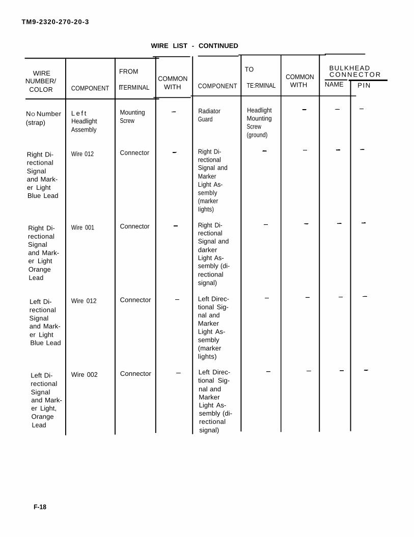
TM9-2320-270-20-3
WIRE LIST - CONTINUED
WIRENUMBER/
COLOR
C O N N E C T O R
PIN
NO Number(strap)
Right Di-rectionalSignaland Mark-er LightBlue Lead
Right Di-rectionalSignaland Mark-er LightOrangeLead
Left Di-rectionalSignaland Mark-er LightBlue Lead
Left Di-rectionalSignaland Mark-er Light,OrangeLead
COMPONENT
L e f tHeadlightAssembly
Wire 012
Wire 001
Wire 012
Wire 002
FROM
TERMINAL
MountingScrew
Connector
Connector
Connector
Connector
COMMONWITH COMPONENT
RadiatorGuard
Right Di-rectionalSignal andMarkerLight As-sembly(markerIights)
Right Di-rectionalSignal anddarkerLight As-sembly (di-rectionalsignal)
Left Direc-tional Sig-nal andMarkerLight As-sembly(markerlights)
Left Direc-tional Sig-nal andMarkerLight As-sembly (di-rectionalsignal)
TO
TE:RMINAL
HeadlightMountingScrew(ground)
COMMONWITH
BULKHEAD
NAME
F-18

TM 9-2320-270-20-3
WIRE LIST - CONTINUED
WIRENUMBER
COLORCONNECTOR
P I N
RightTailliightBrownLead
RightTaillightRed Lead
LeftTaillightBrownLead
LeftTaillightRed Lead
RightBlackoutTaillightLead 23
RightBlackoutTaillightLead 24
LeftBlackoutTaillightLead 23
COMPONENT
Wire 004
Wire 008
Wire 003
Wire 008
Wire 680
Wire 678
Wire 680
FROM
TERMINAL
Connector
Connector
Connector
Connector
Connector
Connector
Connector
COMMONWITH COMPONENT
Right Tail-light As-sembly (di-rectionalsignal)
Right Tail-light As-sembly(taillight)
Left Tail-light As-sembly (di-rectionalsignal)
Left Tail-light As-sembly(taillight)
RightBlackoutTaillightAssembly(blackouttaillight)
RightBlackoutTaillightAssembly(blackoutstoplight)
LeftBlackoutTaillightAssemblyblackouttaillight)
TO
TERMINALCOMMON
WITH
BULKHEAD
NAME
F-19

TM 9-2320-270-20-3
WIRE LIST - CONTINUED
WIRENUMBER/
COLORC O N N E C T O R
NAME PIN
LeftBlackoutTaillightLead 24
TowingKit RedWire
TowingKit BrownWire
COMPONENT
Wire 678
PrimaryStoplightSwitch
PrimaryStoplightSwitch
FROM
TERMINAL
Connector
COMMONWITH
005005
009009
COMPONENT
LeftBlackoutTaillightAssembly(blackoutstoplight)
Towing KitStoplightSwitch
Towing KitStoplightSwitch
TO
TERMINALCOMMON
WITH
BULKHEAD
F - 2 0

TM 9-2320-270-20-3
Section Il. ELECTRICAL SCHEMATIC SYMBOLS
TA240840
F-21

TM 9-2320-270-20-3
ELECTRICAL SCHEMATIC SYMBOLS - CONTINUED
TA240841
F-22

TM9-2320-270-20-3
C h a n g e 1 F - 2 3

TM9-2320-270-20-3
F - 2 4 C h a n g e 1

TM9-2320-270-20-3
C h a n g e 1 F - 2 5

TM 9-2320-270-20-3
F-26 Change 1

TM9-2320-270-20-3
* U.S. GOVERNMENT PRINTING OFFICE: 1991 543-016/40065 Change 1 F-27/(F-28 blank)


TM9-2320-270-20-3
SCHEMATICS - CONTINUED
Air Schematic (Sheet 1 of 3)
T A 2 4 0 8 4 8
F-29

TM9-2320-270-20-3
SCHEMATICS - CONTINUED
Air Schematic (Sheet 2 of 3)T A 2 4 0 8 4 9
F - 3 0

TM9-2320-270-20-3
SCHEMATICS - CONTINUED
Air Schematic (Sheet 3 of 3)
T A 2 4 0 8 5 0
F-31

TM 9-2320-270-20-3
SCHEMATICS - CONTINUED
Hydraulic Schematic (Sheet 1 of 3)
T A 2 4 0 8 5 1
F - 3 2

TM 9-2320-270-20-3
SCHEMATICS - CONTINUED
Hydraulic Schematic (Sheet 2 of 3)
TA240852
F-33

TM9-2320-270-20-3
SCHEMATICS - CONTINUED
Hydraulic Schematic (Sheet 3 of 3)
T A 2 4 0 8 5 3
F-34

TM9-2320-270-20-3
GLOSSARY
Page
Section I. Abbreviations . . . . . . . . . . . . . . . . . . . . . . . . . . . . . . . . . . . . . . . . . . . . . . . . . . . . . . . . . . . . . . . . . . . . . . . . . . . . . . . . . . . . . . . . . . . . . . Glos-1Section Il. Definition of Unusual Terms . . . . . . . . . . . . . . . . . . . . . . . . . . . . . . . . . . . . . . . . . . . . . . . . . . . . . . . . . . . . . . . . . . . . . . Glos-1
Section I. ABBREVIATIONS
BllC-HETEIRFGCFSCMgalHETkPakgkmlbLOMACMODMWON•mNSNpsiptqtradRPSTLSTDTAMMSTACOMTMDETOE
Basic Issue ItemsCommercial Heavy Equipment TransportEquipment Improvement RequestFunctional Group CodeFederal Supply Code for ManufacturersGallonHeavy Equipment TransportKiloposcalsKilogramsKilometersPoundLubrication OrderMaintenance Allocation ChartModificationMaintenance Work OrderNewton MetersNational Stock NumberPounds per square inchPintQuartRadiansRepair Parts and Special Tools ListStandardThe Army Maintenance Management SystemUS Army Tank Automotive CommandTest, Measurement, and Diagnostic EquipmentTable of Organization and Equipment.
Section Il. DEFINITION OF UNUSUAL TERMS
Airbrakes. Brake system where compressed air, controlled by driver operated valve, provides forceto apply brakes.
Air Chamber. Device in airbrake system which turns air pressure into mechanical force to applybrakes.
Glos-1

TM9-2320-270-20-3
Section II. DEFINITION OF UNUSUAL TERMS - CONTINUED
Blind Rivet. Hollow rivet with ball-headed nail through its center. This rivet is installed by specialtool which pulls on nail, expanding unflanged end of rivet securing it, and then breaks off nail.
Brinnelling. Type of wear or damage to bearing characterized by many small dents or pits.
Diesel Engine. internal combustion engine in which fuel-air mixture is ignited by heat generated by compressing air-fuel mixture. Unlike gasoline engine where air-fuel mixture is ignited by electricspark.
Diode. Electronic device which allows electricity to flow in only one direction.
Fifth Wheel. Round coupling and support device mounted on truck tractor to pull semitrailer.
Optical Ribbon. Ribbon made up of glass fibers which carries light.
Pusher Axle. Truck or trailer axle which can be lowered to help support load and raised when notneeded. Used on some roadways which cannot support full load per wheel.
Performed Packing. Round neoprene or synthetic rubber seal or gasket. Also known as an O-ring.
Quick Release Valve. Valve in airbrake system which allows air pressure used to apply brakes, to beexhausted near brake chambers rather than having to exhaust it back through treadle valve. Allowsbrakes to release more quickly.
Relay. Electrical device that allows small current to control larger current.
Relay Valve. Airbrake valve that allows pilot air, small in both volume and pressure, to control larger flow in volume or pressure.
RPSTL. Repair Parts and Special Tools List. Army parts catalog.
Semitrailer. Trailer where part of load is carried by towing vehicle.
Spring Brake Chamber. Device in airbrake system where brakes are normally applied by large springwhile parking or during an air system failure. Spring is held back during driving by air systempressure. Spring brake chambers are installed as safety device in case of an air system failure, and tohold truck while parked.
TOE. Table of Organizational and Equipment. A listing of number and types of personnel andequipment required to makeup an army unit.
Transfer Case. Gearbox which drives drive shafts, which drive front and rear axles.
GIos-2
Treadle Valve. Valve in airbrake system which controls brakes by driver’s foot pedal.

TM 9-2320-270-20-3
I N D E X
Subject. Page
A
Accessories Maintenance . . . . . . . . . . . . . . . . . . . . . . . . . . . . . . . . . . . . . . . . . . . . . . . . . . . . . . . . . . . . . . . . . . . . . . . . . . . . . . . . . . . . . . . . . . . . . . . . . . . . . . . . . . . . . . . . . . . . . . .Adhesive, Data Plates and Decals Secured with . . . . . . . . . . . . . . . . . . . . . . . . . . . . . . . . . . . . . . . . . . . . . . . . . . . . . . . . . . . . . . . . . . . . . . . . . . . . . . . . Air Horn . . . . . . . . . . . . . . . . . . . . . . . . . . . . . . . . . . . . . . . . . . . . . . . . . . . . . . . . . . . . . . . . . . . . . . . . . . . . . . . . . . . . . . . . . . . . . . . . . . . . . . . . . . . . . . . . . . . . . . . . . . . . . . . . . . .. Air Horn Air Lines . . . . . . . . . . . . . . . . . . . . . . . . . . . . . . . . . . . . . . . . . . . . . . . . . . . . . . . . . . . . . . . . . . . . . . . . . . . . . . . . . . . . . . . . . . . . . . . . . . . . . . . . . . . . . . . . . . . . . . . . Air Horn Chain . . . . . . . . . . . . . . . . . . . . . . . . . . . . . . . . . . . . . . . . . . . . . . . . . . . . . . . . . . . . . . . . . . . . . . . . . . . . . . . . . . . . . . . . . . . . . . . . . . . . . . . . . . . . . . . . . . . . . . . . . . . . . . . . . ........ .Air Horn Valve . . . . . . . . . . . . . . . . . . . . . . . . . . . . . . . . . . . . . . . . . . . . . . . . . . . . . . . . . . . . . . . . . . . . . . . . . . . . . . . . . . . . . . . . . . . . . . . . . . . . . . . . . . . . . . . . . . . . . . . . . . . . . . . . . .Air Lines, Air Horn . . . . . . . . . . . . . . . . . . . . . . . . . . . . . . . . . . . . . . . . . . . . . . . . . . . . . . . . . . . . . . . . . . . . . . . . . . . . . . . . . . . . . . . . . . . . . . . . . . . . . . . . . . . . . . . . . . . . . . . . . . . . . . . . . Air Line, Windshield Washer Nylon . . . . . . . . . . . . . . . . . . . . . . . . . . . . . . . . . . . . . . . . . . . . . . . . . . . . . . . . . . . . . . . . . . . . . . . . . . . . . . . . . . . . . . . . . . . . . . . . . . . . . . . .Air Lines, Wiper . . . . . . . . . . . . . . . . . . . . . . . . . . . . . . . . . . . . . . . . . . . . . . . . . . . . . . . . . . . . . . . . . . . . . . . . . . . . . . . . . . . . . . . . . . . . . . . . . . . . . . . . . . . . . . . . . . . . . . . . . . . . . . . . . . .Air Load Control Valve, Pusher Axle . . . . . . . . . . . . . . . . . . . . . . . . . . . . . . . . . . . . . . . . . . . . . . . . . . . . . . . . . . . . . . . . . . . . . . . . . . . . . . . . . . . . . . . . . . . . . . . . . . . . Air Pilot Valve, Left . . . . . . . . . . . . . . . . . . . . . . . . . . . . . . . . . . . . . . . . . . . . . . . . . . . . . . . . . . . . . . . . . . . . . . . . . . . . . . . . . . . . . . . . . . . . . . . . . . . . . . . . . . . . . . . . . . . . . . . . . . . . . . . .Air Pilot Valve, Right . . . . . . . . . . . . . . . . . . . . . . . . . . . . . . . . . . . . . . . . . . . . . . . . . . . . . . . . . . . . . . . . . . . . . . . . . . . . . . . . . . . . . . . . . . . . . . . . . . . . . . . . . . . . . . . . . . . . . . . . . . . . . . . .Air Pressure Gage . . . . . . . . . . . . . . . . . . . . . . . . . . . . . . . . . . . . . . . . . . . . . . . . . . . . . . . . . . . . . . . . . . . . . . . . . . . . . . . . . . . . . . . . . . . . . . . . . . . . . . . . . . . . . . . . . . . . . . . . . . . . . . Alinement, Steering . . . . . . . . . . . . . . . . . . . . . . . . . . . . . . . . . . . . . . . . . . . . . . . . . . . . . . . . . . . . . . . . . . . . . . . . . . . . . . . . . . . . . . . . . . . . . . . . . . . . . . . . . . . . . . . . . . . . . . . . . . . . . . . Appendix A, References . . . . . . . . . . . . . . . . . . . . . . . . . . . . . . . . . . . . . . . . . . . . . . . . . . . . . . . . . . . . . . . . . . . . . . . . . . . . . . . . . . . . . . . . . . . . . . . . . . . . . . . . . . . . . . . . . . . . . . . . . .Appendix B, Maintenance Allocation Chart . . . . . . . . . . . . . . . . . . . . . . . . . . . . . . . . . . . . . . . . . . . . . . . . . . . . . . . . . . . . . . . . . . . . . . . . . . . . . . . . . . . . . . . . . . .Appendix C, Expendable Supplies and Materials List . . . . . . . . . . . . . . . . . . . . . . . . . . . . . . . . . . . . . . . . . . . . . . . . . . . . . . . . . . . . . . . . . . . . . . . . .Appendix D, Manufactured items (Not Applicable) . . . . . . . . . . . . . . . . . . . . . . . . . . . . . . . . . . . . . . . . . . . . . . . . . . . . . . . . . . . . . . . . . . . . . . . . . . . . . . .Appendix E, Torque Limits . . . . . . . . . . . . . . . . . . . . . . . . . . . . . . . . . . . . . . . . . . . . . . . . . . . . . . . . . . . . . . . . . . . . . . . . . . . . . . . . . . . . . . . . . . . . . . . . . . . . . . . . . . . . . . . . . . . . . .Appendix F, Schematic Diagrams . . . . . . . . . . . . . . . . . . . . . . . . . . . . . . . . . . . . . . . . . . . . . . . . . . . . . . . . . . . . . . . . . . . . . . . . . . . . . . . . . . . . . . . . . . . . . . . . . . . . . . . . . .Arm and Blade, Wiper . . . . . . . . . . . . . . . . . . . . . . . . . . . . . . . . . . . . . . . . . . . . . . . . . . . . . . . . . . . . . . . . . . . . . . . . . . . . . . . . . . . . . . . . . . . . . . . . . . . . . . . . . . . . . . . . . . . . . . . . . . . . . .Arm, Pitman . . . . . . . . . . . . . . . . . . . . . . . . . . . . . . . . . . . . . . . . . . . . . . . . . . . . . . . . . . . . . . . . . . . . . . . . . . . . . . . . . . . . . . . . . . . . . . . . . . . . . . . . . . . . . . . . . . . . . . . . . . . . . . . . . . .Ashtray . . . . . . . . . . . . . . . . . . . . . . . . . . . . . . . . . . . . . . . . . . . . . . . . . . . . . . . . . . . . . . . . . . . . . . . . . . . . . . . . . . . . . . . . . . . . . . . . . . . . . . . . . . . . . . . . . . . . . . . . . . . . . . . . . .........
4-11774-12244-12514-12604-12494-12444-12604-11854-12084-10794-10654-10704-13304-1035A-1B-1C-1D-1E-1F-14-12054-9784-1123
Battery Box Bracket Pressure Hose, Power Steering Pump to . . . . . . . . . . . . . . . . . . . . . . . . . . . . . . . . . . . . . . . . . . . . . . . . . . . . . . . . . . . .Battery Box Bracket Hose, Reservoir to . . . . . . . . . . . . . . . . . . . . . . . . . . . . . . . . . . . . . . . . . . . . . . . . . . . . . . . . . . . . . . . . . . . . . . . . . . . . . . . . . . . . . . . . . . . . . . . . .Battery Box Bracket to Booster Hoses . . . . . . . . . . . . . . . . . . . . . . . . . . . . . . . . . . . . . . . . . . . . . . . . . . . . . . . . . . . . . . . . . . . . . . . . . . . . . . . . . . . . . . . . . . . . . . . . . . .Belts, Seat . . . . . . . . . . . . . . . . . . . . . . . . . . . . . . . . . . . . . . . . . . . . . . . . . . . . . . . . . . . . . . . . . . . . . . . . . . . . . . . . . . . . . . . . . . . . . . . . . . . . . . . . . . . . . . . . . . . . . . . . . . . . . . . . . Bezels, Heater Control Panel . . . . . . . . . . . . . . . . . . . . . . . . . . . . . . . . . . . . . . . . . . . . . . . . . . . . . . . . . . . . . . . . . . . . . . . . . . . . . . . . . . . . . . . . . . . . . . . . . . . . . . . . . . . . . . . . . .Blade, Wiper Arm and . . . . . . . . . . . . . . . . . . . . . . . . . . . . . . . . . . . . . . . . . . . . . . . . . . . . . . . . . . . . . . . . . . . . . . . . . . . . . . . . . . . . . . . . . . . . . . . . . . . . . . . . . . . . . . . . . . . . . . . . . . . . . .Blind Rivets, Data Plates Secured with . . . . . . . . . . . . . . . . . . . . . . . . . . . . . . . . . . . . . . . . . . . . . . . . . . . . . . . . . . . . . . . . . . . . . . . . . . . . . . . . . . . . . . . . . . . . . . . . . .Booster Cylinder . . . . . . . . . . . . . . . . . . . . . . . . . . . . . . . . . . . . . . . . . . . . . . . . . . . . . . . . . . . . . . . . . . . . . . . . . . . . . . . . . . . . . . . . . . . . . . . . . . . . . . . . . . . . . . . . . . . . . . . . . . . . . . . . . .Booster Drag Link, Pitman Arm to . . . . . . . . . . . . . . . . . . . . . . . . . . . . . . . . . . . . . . . . . . . . . . . . . . . . . . . . . . . . . . . . . . . . . . . . . . . . . . . . . . . . . . . . . . . . .. . . . . . . . . . .Booster Drag Link, Wheel to . . . . . . . . . . . . . . . . . . . . . . . . . . . . . . . . . . . . . . . . . . . . . . . . . . . . . . . . . . . . . . . . . . . . . . . . . . . . . . . . . . . . . . . . . . . . . . . . . . . . . . . . . . . . . . . . . . . .Booster Hoses, Battery Box Brackets to . . . . . . . . . . . . . . . . . . . . . . . . . . . . . . . . . . . . . . . . . . . . . . . . . . . . . . . . . . . . . . . . . . . . . . . . . . . . . . . . . . . . . . . . . . . . . . . .Brace, Dash . . . . . . . . . . . . . . . . . . . . . . . . . . . . . . . . . . . . . . . . . . . . . . . . . . . . . . . . . . . . . . . . . . . . . . . . . . . . . . . . . . . . . . . . . . . . . . . . . . . . . . . . . . . . . . . . . . . . . . . . . . . . . . . . . ...Bracket to Booster Hoses, Battery Box . . . . . . . . . . . . . . . . . . . . . . . . . . . . . . . . . . . . . . . . . . . . . . . . . . . . . . . . . . . . . . . . . . . . . . . . . . . . . . . . . . . . . . . . . . . . . . . . . .Bracket, Pitman Arm Stop . . . . . . . . . . . . . . . . . . . . . . . . . . . . . . . . . . . . . . . . . . . . . . . . . . . . . . . . . . . . . . . . . . . . . . . . . . . . . . . . . . . . . . . . . . . . . . . . . . . . . . . . . . . . . . . . . . . . . . .Brackets and Towing Eyes, Front Bumper . . . . . . . . . . . . . . . . . . . . . . . . . . . . . . . . . . . . . . . . . . . . . . . . . . . . . . . . . . . . . . . . . . . . . . . . . . . . . . . . . . . . . . . . . . . . .Bracket, Steering Column . . . . . . . . . . . . . . . . . . . . . . . . . . . . . . . . . . . . . . . . . . . . . . . . . . . . . . . . . . . . . . . . . . . . . . . . . . . . . . . . . . . . . . . . . . . . . . . . . . . . . . . . . . . . . . . . . . . . . . . .Bracket, Spotter Mirror Head and . . . . . . . . . . . . . . . . . . . . . . . . . . . . . . . . . . . . . . . . . . . . . . . . . . . . . . . . . . . . . . . . . . . . . . . . . . . . . . . . . . . . . . . . . . . . . . . . . . . . . . . .Bumper, Front . . . . . . . . . . . . . . . . . . . . . . . . . . . . . . . . . . . . . . . . . . . . . . . . . . . . . . . . . . . . . . . . . . . . . . . . . . . . . . . . . . . . . . . . . . . . . . . . . . . . . . . . . . . . . . . . . . . . . . . . . . . . . . . . . . ...
4-9994-9934-10044-11304-13124-12054-13224-10164-9624-9554-10044-9434-10044-9744-10514-9404-12424-1042
Index-1

TM9-2320-270-20-3
INDEX - CONTINUED
S u b j e c t Page
C
Cab and Body Maintenance . . . . . . . . . . . . . . . . . . . . . . . . . . . . . . . . . . . . . . . . . . . . . . . . . . . . . . . . . . . . . . . . . . . . . . . . . . . . . . . . . . . . . . . . . . . . . . . . . . . . . . . . . . . . . . . . . . . .Cable, Defroster Knob and . . . . . . . . . . . . . . . . . . . . . . . . . . . . . . . . . . . . . . . . . . . . . . . . . . . . . . . . . . . . . . . . . . . . . . . . . . . . . . . . . . . . . . . . . . . . . . . . . . . . . . . . . . . . . . . . . . . . . .Cable, Heater Knob and . . . . . . . . . . . . . . . . . . . . . . . . . . . . . . . . . . . . . . . . . . . . . . . . . . . . . . . . . . . . . . . . . . . . . . . . . . . . . . . . . . . . . . . . . . . . . . . . . . . . . . . . . . . . . . . . . . . . . . . ..Cable, Spare Tire, Winch, and . . . . . . . . . . . . . . . . . . . . . . . . . . . . . . . . . . . . . . . . . . . . . . . . . . . . . . . . . . . . . . . . . . . . . . . . . . . . . . . . . . . . . . . . . . . . . . . . . . . . . . . . . . . . . . . . .Cable, Winch . . . . . . . . . . . . . . . . . . . . . . . . . . . . . . . . . . . . . . . . . . . . . . . . . . . . . . . . . . . . . . . . . . . . . . . . . . . . . . . . . . . . . . . . . . . . . . . . . . . . . . . . . . . . . . . . . . . . . . . . . . . . . . . . . . .. .........Chain, Air Horn . . . . . . . . . . . . . . . . . . . . . . . . . . . . . . . . . . . . . . . . . . . . . . . . . . . . . . . . . . . . . . . . . . . . . . . . . . . . . . . . . . . . . . . . . . . . . . . . . . . . . ... . . . . . . . . . . . . . . . . . . . . . . . . . . . . .Column Bracket, Steering . . . . . . . . . . . . . . . . . . . . . . . . . . . . . . . . . . . . . . . . . . . . . . . . . . . . . . . . . . . . . . . . . . . . . . . . . . . . . . . . . . . . . . . . . . . . . . . . . . . . . . . . . . . . . . . . . . . . .Coolant Return Elbow, Heater . . . . . . . . . . . . . . . . . . . . . . . . . . . . . . . . . . . . . . . . . . . . . . . . . . . . . . . . . . . . . . . . . . . . . . . . . . . . . . . . . . . . . . . . . . . . . . . . . . . . . . . . . . . . . . . . .Control Panel Bezels, Heater . . . . . . . . . . . . . . . . . . . . . . . . . . . . . . . . . . . . . . . . . . . . . . . . . . . . . . . . . . . . . . . . . . . . . . . . . . . . . . . . . . . . . . . . . . . . . . . . . . . . . . . . . . . . . . . . . .Control Panel, Heater . . . . . . . . . . . . . . . . . . . . . . . . . . . . . . . . . . . . . . . . . . . . . . . . . . . . . . . . . . . . . . . . . . . . . . . . . . . . . . . . . . . . . . . . . . . . . . . . . . . . . . . . . . . . . . . . . . . . . . . . . . . . . . .Control Panel Optical Ribbon, Heater . . . . . . . . . . . . . . . . . . . . . . . . . . . . . . . . . . . . . . . . . . . . . . . . . . . . . . . . . . . . . . . . . . . . . . . . . . . . . . . . . . . . . . . . . . . . . . . . . . . .Control Valve, Pusher Axle Air Load . . . . . . . . . . . . . . . . . . . . . . . . . . . . . . . . . . . . . . . . . . . . . . . . . . . . . . . . . . . . . . . . . . . . . . . . . . . . . . . . . . . . . . . . . . . . . . . . . . . . . . .Control Valve, Winch . . . . . . . . . . . . . . . . . . . . . . . . . . . . . . . . . . . . . . . . . . . . . . . . . . . . . . . . . . . . . . . . . . . . . . . . . . . . . . . . . . . . . . . . . . . . . . . . . . . . . . . . . . . . . . . . . . . . . . . . . . . . . . . .Control Valve, Windshield Washer . . . . . . . . . . . . . . . . . . . . . . . . . . . . . . . . . . . . . . . . . . . . . . . . . . . . . . . . . . . . . . . . . . . . . . . . . . . . . . . . . . . . . . . . . . . . . . . . . . . . . . . . .Control Valve, Wiper . . . . . . . . . . . . . . . . . . . . . . . . . . . . . . . . . . . . . . . . . . . . . . . . . . . . . . . . . . . . . . . . . . . . . . . . . . . . . . . . . . . . . . . . . . . . . . . . . . . . . . . . . . . . . . . . . . . . . . . . . . . . . . . . .Convex Mirror Head . . . . . . . . . . . . . . . . . . . . . . . . . . . . . . . . . . . . . . . . . . . . . . . . . . . . . . . . . . . . . . . . . . . . . . . . . . . . . . . . . . . . . . . . . . . . . . . . . . . . . . . . . . . . . . . . . . . . . . . . . . . . . . . . .Core, Heater . . . . . . . . . . . . . . . . . . . . . . . . . . . . . . . . . . . . . . . . . . . . . . . . . . . . . . . . . . . . . . . . . . . . . . . . . . . . . . . . . . . . . . . . . . . . . . . . . . . . . . . . . . . . . . . . . . . . . . . . . . . . . . . . . .... .........Crossbar Supports . . . . . . . . . . . . . . . . . . . . . . . . . . . . . . . . . . . . . . . . . . . . . . . . . . . . . . . . . . . . . . . . . . . . . . . . . . . . . . . . . . . . . . . . . . . . . . . . . . . . . . . . . . . . . . . . . . . . . . . . . . . . . . . . . . .Cylinder, Booster . . . . . . . . . . . . . . . . . . . . . . . . . . . . . . . . . . . . . . . . . . . . . . . . . . . . . . . . . . . . . . . . . . . . . . . . . . . . . . . . . . . . . . . . . . . . . . . . . . . . . . . . . . . . . . . . . . . . . . . . . . . . . . . . . . .. ..
D
Dash Brace . . . . . . . . . . . . . . . . . . . . . . . . . . . . . . . . . . . . . . . . . . . . . . . . . . . . . . . . . . . . . . . . . . . . . . . . . . . . . . . . . . . . . . . . . . . . . . . . . . . . . . . . . . . . . . . . . . . . . . . . . . . . . . . . . .... ...........Data Plate, Engine . . . . . . . . . . . . . . . . . . . . . . . . . . . . . . . . . . . . . . . . . . . . . . . . . . . . . . . . . . . . . . . . . . . . . . . . . . . . . . . . . . . . . . . . . . . . . . . . . . . . . . . . . . . . . . . . . . . . . . . . . . . . . . . . . ...Data Plates and Decals Secured with Adhesive . . . . . . . . . . . . . . . . . . . . . . . . . . . . . . . . . . . . . . . . . . . . . . . . . . . . . . . . . . . . . . . . . . . . . . . . . . . . . . . . . . . .Data Plates Secured with Blind Rivets . . . . . . . . . . . . . . . . . . . . . . . . . . . . . . . . . . . . . . . . . . . . . . . . . . . . . . . . . . . . . . . . . . . . . . . . . . . . . . . . . . . . . . . . . . . . . . . . . . .Data Plates Secured with Drivescrews . . . . . . . . . . . . . . . . . . . . . . . . . . . . . . . . . . . . . . . . . . . . . . . . . . . . . . . . . . . . . . . . . . . . . . . . . . . . . . . . . . . . . . . . . . . . . . . . . . .Data Plates Secured with Self-Tapping Screws . . . . . . . . . . . . . . . . . . . . . . . . . . . . . . . . . . . . . . . . . . . . . . . . . . . . . . . . . . . . . . . . . . . . . . . . . . . . . . . . . . . . .Decals Secured with Adhesive, Data Plates and . . . . . . . . . . . . . . . . . . . . . . . . . . . . . . . . . . . . . . . . . . . . . . . . . . . . . . . . . . . . . . . . . . . . . . . . . . . . . . . . . . .Deflector, Heater . . . . . . . . . . . . . . . . . . . . . . . . . . . . . . . . . . . . . . . . . . . . . . . . . . . . . . . . . . . . . . . . . . . . . . . . . . . . . . . . . . . . . . . . . . . . . . . . . . . . . . . . . . . . . . . . . . . . . . . . . . . . . . . . . Defroster Hose . . . . . . . . . . . . . . . . . . . . . . . . . . . . . . . . . . . . . . . . . . . . . . . . . . . . . . . . . . . . . . . . . . . . . . . . . . . . . . . . . . . . . . . . . . . . . . . . . . . . . . . . . . . . . . . . . . . . . . . . . . . . . . . . . .... ....Defroster Knob and Cable . . . . . . . . . . . . . . . . . . . . . . . . . . . . . . . . . . . . . . . . . . . . . . . . . . . . . . . . . . . . . . . . . . . . . . . . . . . . . . . . . . . . . . . . . . . . . . . . . . . . . . . . . . . . . . . . . . . . . . .Defroster Nozzle . . . . . . . . . . . . . . . . . . . . . . . . . . . . . . . . . . . . . . . . . . . . . . . . . . . . . . . . . . . . . . . . . . . . . . . . . . . . . . . . . . . . . . . . . . . . . . . . . . . . . . . . . . . . . . . . . . . . . . . . . . . . . . . . . ..... .Detent Loop Assembly, Mirror . . . . . . . . . . . . . . . . . . . . . . . . . . . . . . . . . . . . . . . . . . . . . . . . . . . . . . . . . . . . . . . . . . . . . . . . . . . . . . . . . . . . . . . . . . . . . . . . . . . . . . . . . . . . . . . . .Drag Link, Pitman Arm to Booster . . . . . . . . . . . . . . . . . . . . . . . . . . . . . . . . . . . . . . . . . . . . . . . . . . . . . . . . . . . . . . . . . . . . . . . . . . . . . . . . . . . . . . . . . . . . . . . . . . . . . . . . . .Drag Link, Wheel to Booster . . . . . . . . . . . . . . . . . . . . . . . . . . . . . . . . . . . . . . . . . . . . . . . . . . . . . . . . . . . . . . . . . . . . . . . . . . . . . . . . . . . . . . . . . . . . . . . . . . . . . . . . . . . . . . . . . . . .Draining and Filling, Hydraulic Reservoir . . . . . . . . . . . . . . . . . . . . . . . . . . . . . . . . . . . . . . . . . . . . . . . . . . . . . . . . . . . . . . . . . . . . . . . . . . . . . . . . . . . . . . . . . . . . . .Driver’s Seat and Support . . . . . . . . . . . . . . . . . . . . . . . . . . . . . . . . . . . . . . . . . . . . . . . . . . . . . . . . . . . . . . . . . . . . . . . . . . . . . . . . . . . . . . . . . . . . . . . . . . . . . . . . . . . . . . . . . . . . . . . .Drivescrews, Data Plates Secured with . . . . . . . . . . . . . . . . . . . . . . . . . . . . . . . . . . . . . . . . . . . . . . . . . . . . . . . . . . . . . . . . . . . . . . . . . . . . . . . . . . . . . . . . . . . . . . . . . .
E
4-1088 4-12724-12844-10554-11404-12494-9404-13194-13124-13074-13124-10794-11574-11824-11574-12284-12654-10964-1016
4-9434-13294-12244-13224-13254-13274-12244-12884-12904-12724-12894-12294-9624-9554-11604-11274-1325
Elbow, Heater Coolant Return . . . . . . . . . . . . . . . . . . . . . . . . . . . . . . . . . . . . . . . . . . . . . . . . . . . . . . . . . . . . . . . . . . . . . . . . . . . . . . . . . . . . . . . . . . . . . . . . . . . . . . . . . . . . ... 4-1319 Engine Data Plate . . . . . . . . . . . . . . . . . . . . . . . . . . . . . . . . . . . . . . . . . . . . . . . . . . . . . . . . . . . . . . . . . . . . . . . . . . . . . . . . . . . . . . . . . . . . . . . . . . . . . . . . . . . . . . . . . . . . . . . . . . . . . . . . . .... 4-1329Expendable Supplies and Materials List . . . . . . . . . . . . . . . . . . . . . . . . . . . . . . . . . . . . . . . . . . . . . . . . . . . . . . . . . . . . . . . . . . . . . . . . . . . . . . . . . . . . . . . . . . . . . . . . C-1
I n d e x - 2

TM9-2320-270-20-3
INDEX
Subject Page
F
Fifth Wheel Oscillator Lockouts . . . . . . . . . . . . . . . . . . . . . . . . . . . . . . . . . . . . . . . . . . . . . . . . . . . . . . . . . . . . . . . . . . . . . . . . . . . . . . . . . . . . . . . . . . . . . . . . . . . . . . . . . . . . . 4-1064‘Floor Mat . . . . . . . . . . . . . . . . . . . . . . . . . . . . . . . . . . . . . . . . . . . . . . . . . . . . . . . . . . . . . . . . . . . . . . . . . . . . . . . . . . . . . . . . . . . . . . . . . . . . . . . . . . . . . . . . . . . . . . . . . . . . . . . . . . .. . 4-1134Frame and Towing Attachment Maintenance . . . . . . . . . . . . . . . . . . . . . . . . . . . . . . . . . . . . . . . . . . . . . . . . . . . . . . . . . . . . . . . . . . . . . . . . . . . . . . . . . . . . . . . 4-1042Front Bumper . . . . . . . . . . . . . . . . . . . . . . . . . . . . . . . . . . . . . . . . . . . . . . . . . . . . . . . . . . . . . . . . . . . . . . . . . . . . . . . . . . . . . . . . . . . . . . . . . . . . . . . . . . . . . . . . . . . . . . . . . . . . . . . . . . .. 4-1042Front Bumper Brackets and Towing Eyes . . . . . . . . . . . . . . . . . . . . . . . . . . . . . . . . . . . . . . . . . . . . . . . . . . . . . . . . . . . . . . . . . . . . . . . . . . . . . . . . . . . . . . . . . . . . . . 4-1051Front Spring Pins . . . . . . . . . . . . . . . . . . . . . . . . . . . . . . . . . . . . . . . . . . . . . . . . . . . . . . . . . . . . . . . . . . . . . . . . . . . . . . . . . . . . . . . . . . . . . . . . . . . . . . . . . . . . . . . . . . . . . . . . . . . . . . . . . . .. 4-1074
G
Gage, Air Pressure . . . . . . . . . . . . . . . . . . . . . . . . . . . . . . . . . . . . . . . . . . . . . . . . . . . . . . . . . . . . . . . . . . . . . . . . . . . . . . . . . . . . . . . . . . . . . . . . . . . . . . . . . . . . . . . . . . . . . . . . . . . . . . . . . . 4-1330Gages, Non-Electric . . . . . . . . . . . . . . . . . . . . . . . . . . . . . . . . . . . . . . . . . . . . . . . . . . . . . . . . . . . . . . . . . . . . . . . . . . . . . . . . . . . . . . . . . . . . . . . . . . . . . . . . . . . . . . . . . . . . . . . . . . . . . . . 4-1330Gear, Steering . . . . . . . . . . . . . . . . . . . . . . . . . . . . . . . . . . . . . . . . . . . . . . . . . . . . . . . . . . . . . . . . . . . . . . . . . . . . . . . . . . . . . . . . . . . . . . . . . . . . . . . . . . . . . . . . . . . . . . . . . . . . . . . . . . . 4-981Glossary . . . . . . . . . . . . . . . . . . . . . . . . . . . . . . . . . . . . . . . . . . . . . . . . . . . . . . . . . . . . . . . . . . . . . . . . . . . . . . . . . . . . . . . . . . . . . . . . . . . . . . . . . . . . . . . . . . . . . . . . . . . . . . . . . . .. .... GLOS-
1Grab Handle . . . . . . . . . . . . . . . . . . . . . . . . . . . . . . . . . . . . . . . . . . . . . . . . . . . . . . . . . . . . . . . . . . . . . . . . . . . . . . . . . . . . . . . . . . . . . . . . . . . . . . . . . . . . . . . . . . . . . . . . . . . . . . . . . . .......... 4-1118Grease Fitting, Steering Shaft . . . . . . . . . . . . . . . . . . . . . . . . . . . . . . . . . . . . . . . . . . . . . . . . . . . . . . . . . . . . . . . . . . . . . . . . . . . . . . . . . . . . . . . . . . . . . . . . . . . . . . . . . . . . . . . . . 4-953Guard, Radiator and Headlight . . . . . . . . . . . . . . . . . . . . . . . . . . . . . . . . . . . . . . . . . . . . . . . . . . . . . . . . . . . . . . . . . . . . . . . . . . . . . . . . . . . . . . . . . . . . . . . . . . . . . . . . . . . . . . . 4-1088
H
Handle, Grab . . . . . . . . . . . . . . . . . . . . . . . . . . . . . . . . . . . . . . . . . . . . . . . . . . . . . . . . . . . . . . . . . . . . . . . . . . . . . . . . . . . . . . . . . . . . . . . . . . . . . . . . . . . . . . . . . . . . . . . . . . . . . . . . . . .......Head and Bracket, Spotter Mirror . . . . . . . . . . . . . . . . . . . . . . . . . . . . . . . . . . . . . . . . . . . . . . . . . . . . . . . . . . . . . . . . . . . . . . . . . . . . . . . . . . . . . . . . . . . . . . . . . . . . . . . . . . .Head, Convex Mirror . . . . . . . . . . . . . . . . . . . . . . . . . . . . . . . . . . . . . . . . . . . . . . . . . . . . . . . . . . . . . . . . . . . . . . . . . . . . . . . . . . . . . . . . . . . . . . . . . . . . . . . . . . . . . . . . . . . . . . . . . . . . . . . .Headlight Guard, Radiator and . . . . . . . . . . . . . . . . . . . . . . . . . . . . . . . . . . . . . . . . . . . . . . . . . . . . . . . . . . . . . . . . . . . . . . . . . . . . . . . . . . . . . . . . . . . . . . . . . . . . . . . . . . . . . . .Head, Rear View Mirror . . . . . . . . . . . . . . . . . . . . . . . . . . . . . . . . . . . . . . . . . . . . . . . . . . . . . . . . . . . . . . . . . . . . . . . . . . . . . . . . . . . . . . . . . . . . . . . . . . . . . . . . . . . . . . . . . . . . . . . . . . . .Heater Assembly . . . . . . . . . . . . . . . . . . . . . . . . . . . . . . . . . . . . . . . . . . . . . . . . . . . . . . . . . . . . . . . . . . . . . . . . . . . . . . . . . . . . . . . . . . . . . . . . . . . . . . . . . . . . . . . . . . . . . . . . . . . . . . . . . . .Heater Coolant Return Elbow . . . . . . . . . . . . . . . . . . . . . . . . . . . . . . . . . . . . . . . . . . . . . . . . . . . . . . . . . . . . . . . . . . . . . . . . . . . . . . . . . . . . . . . . . . . . . . . . . . . . . . . . . . . . . . . . . .Heater Control Panel . . . . . . . . . . . . . . . . . . . . . . . . . . . . . . . . . . . . . . . . . . . . . . . . . . . . . . . . . . . . . . . . . . . . . . . . . . . . . . . . . . . . . . . . . . . . . . . . . . . . . . . . . . . . . . . . . . . . . . . . . . . . . . . .Heater Control Panel Bezels . . . . . . . . . . . . . . . . . . . . . . . . . . . . . . . . . . . . . . . . . . . . . . . . . . . . . . . . . . . . . . . . . . . . . . . . . . . . . . . . . . . . . . . . . . . . . . . . . . . . . . . . . . . . . . . . . . .Heater Control Panel Optical Ribbon . . . . . . . . . . . . . . . . . . . . . . . . . . . . . . . . . . . . . . . . . . . . . . . . . . . . . . . . . . . . . . . . . . . . . . . . . . . . . . . . . . . . . . . . . . . . . . . . . . . . .Heater Core . . . . . . . . . . . . . . . . . . . . . . . . . . . . . . . . . . . . . . . . . . . . . . . . . . . . . . . . . . . . . . . . . . . . . . . . . . . . . . . . . . . . . . . . . . . . . . . . . . . . . . . . . . . . . . . . . . . . . . . . . . . . . . . . . . .. .....Heater Deflector . . . . . . . . . . . . . . . . . . . . . . . . . . . . . . . . . . . . . . . . . . . . . . . . . . . . . . . . . . . . . . . . . . . . . . . . . . . . . . . . . . . . . . . . . . . . . . . . . . . . . . . . . . . . . . . . . . . . . . . . . . . . . . . . . . .. .Heater Hoses . . . . . . . . . . . . . . . . . . . . . . . . . . . . . . . . . . . . . . . . . . . . . . . . . . . . . . . . . . . . . . . . . . . . . . . . . . . . . . . . . . . . . . . . . . . . . . . . . . . . . . . . . . . . . . . . . . . . . . . . . . . . . . . . . . .. Heater Knob and Cable . . . . . . . . . . . . . . . . . . . . . . . . . . . . . . . . . . . . . . . . . . . . . . . . . . . . . . . . . . . . . . . . . . . . . . . . . . . . . . . . . . . . . . . . . . . . . . . . . . . . . . . . . . . . . . . . . . . . . . . . . . . .Heater Motor . . . . . . . . . . . . . . . . . . . . . . . . . . . . . . . . . . . . . . . . . . . . . . . . . . . . . . . . . . . . . . . . . . . . . . . . . . . . . . . . . . . . . . . . . . . . . . . . . . . . . . . . . . . . . . . . . . . . . . . . . . . . . . . . . .Heater Motor Suppressor . . . . . . . . . . . . . . . . . . . . . . . . . . . . . . . . . . . . . . . . . . . . . . . . . . . . . . . . . . . . . . . . . . . . . . . . . . . . . . . . . . . . . . . . . . . . . . . . . . . . . . . . . . . . . . . . . . . . . . . .Heater Resistor . . . . . . . . . . . . . . . . . . . . . . . . . . . . . . . . . . . . . . . . . . . . . . . . . . . . . . . . . . . . . . . . . . . . . . . . . . . . . . . . . . . . . . . . . . . . . . . . . . . . . . . . . . . . . . . . . . . . . . . . . . . . . . . . . ...Heater Shutoff Valve . . . . . . . . . . . . . . . . . . . . . . . . . . . . . . . . . . . . . . . . . . . . . . . . . . . . . . . . . . . . . . . . . . . . . . . . . . . . . . . . . . . . . . . . . . . . . . . . . . . . . . . . . . . . . . . . . . . . . . . . . . . . . . . .Heater Switch . . . . . . . . . . . . . . . . . . . . . . . . . . . . . . . . . . . . . . . . . . . . . . . . . . . . . . . . . . . . . . . . . . . . . . . . . . . . . . . . . . . . . . . . . . . . . . . . . . . . . . . . . . . . . . . . . . . . . . . . . . . . . . . . . Hood . . . . . . . . . . . . . . . . . . . . . . . . . . . . . . . . . . . . . . . . . . . . . . . . . . . . . . . . . . . . . . . . . . . . . . . . . . . . . . . . . . . . . . . . . . . . . . . . . . . . . . . . . . . . . . . . . . . . . . . . . . . . . . . . . . .. .. .Horn, Air . . . . . . . . . . . . . . . . . . . . . . . . . . . . . . . . . . . . . . . . . . . . . . . . . . . . . . . . . . . . . . . . . . . . . . . . . . . . . . . . . . . . . . . . . . . . . . . . . . . . . . . . . . . . . . . . . . . . . . . . . . . . . . . . . .Horn Air Lines. Air . . . . . . . . . . . . . . . . . . . . . . . . . . . . . . . . . . . . . . . . . . . . . . . . . . . . . . . . . . . . . . . . . . . . . . . . . . . . . . . . . . . . . . . . . . . . . . . . . . . . . . . . . . . . . . . . . . . . . . . . . . . . . . . ...Hose, Defroster . . . . . . . . . . . . . . . . . . . . . . . . . . . . . . . . . . . . . . . . . . . . . . . . . . . . . . . . . . . . . . . . . . . . . . . . . . . . . . . . . . . . . . . . . . . . . . . . . . . . . . . . . . . . . . . . . . . . . . . . . . . . . . . . . . . .....
4-11184-12424-12284-10884-12264-12754-13194-13074-13124-13124-12654-12884-12934-12844-12704-13164-13154-13024-13124-10934-12514-12604-1290
Index-3

TM9-2320-270-20-3
INDEX - CONTINUED
Subject
H - Continued
Page
Hose, Power Steering Pump Supply . . . . . . . . . . . . . . . . . . . . . . . . . . . . . . . . . . . . . . . . . . . . . . . . . . . . . . . . . . . . . . . . . . . . . . . . . . . . . . . . . . . . . . . . . . . . . . . . . . . . . . .Hose, Power Steering Pump to Battery Box Bracket Pressure . . . . . . . . . . . . . . . . . . . . . . . . . . . . . . . . . . . . . . . . . . . . . . . . . . . . . . . . . . . .Hose, Power Steering Pump to Reservoir Return . . . . . . . . . . . . . . . . . . . . . . . . . . . . . . . . . . . . . . . . . . . . . . . . . . . . . . . . . . . . . . . . . . . . . . . . . . . . . . . . . .Hose, Reservoir to Battery Box Bracket . . . . . . . . . . . . . . . . . . . . . . . . . . . . . . . . . . . . . . . . . . . . . . . . . . . . . . . . . . . . . . . . . . . . . . . . . . . . . . . . . . . . . . . . . . . . . . . . .Hoses, Heater . . . . . . . . . . . . . . . . . . . . . . . . . . . . . . . . . . . . . . . . . . . . . . . . . . . . . . . . . . . . . . . . . . . . . . . . . . . . . . . . . . . . . . . . . . . . . . . . . . . . . . . . . . . . . . . . . . . . . . . . . . . . . . . . . ..... .....Hose, Windshield Washer Rubber . . . . . . . . . . . . . . . . . . . . . . . . . . . . . . . . . . . . . . . . . . . . . . . . . . . . . . . . . . . . . . . . . . . . . . . . . . . . . . . . . . . . . . . . . . . . . . . . . . . . . . . . . .Hydraulic Lines, Pump to Winch Valves . . . . . . . . . . . . . . . . . . . . . . . . . . . . . . . . . . . . . . . . . . . . . . . . . . . . . . . . . . . . . . . . . . . . . . . . . . . . . . . . . . . . . . . . . . . . . . . . .Hydraulic Lines, Winch Valves to Motors . . . . . . . . . . . . . . . . . . . . . . . . . . . . . . . . . . . . . . . . . . . . . . . . . . . . . . . . . . . . . . . . . . . . . . . . . . . . . . . . . . . . . . . . . . . . . .Hydraulic Oil Filter . . . . . . . . . . . . . . . . . . . . . . . . . . . . . . . . . . . . . . . . . . . . . . . . . . . . . . . . . . . . . . . . . . . . . . . . . . . . . . . . . . . . . . . . . . . . . . . . . . . . . . . . . . . . . . . . . . . . . . . . . . . . . . . . . . .Hydraulic Reservoir . . . . . . . . . . . . . . . . . . . . . . . . . . . . . . . . . . . . . . . . . . . . . . . . . . . . . . . . . . . . . . . . . . . . . . . . . . . . . . . . . . . . . . . . . . . . . . . . . . . . . . . . . . . . . . . . . . . . . . . . . . . . . . . . . .Hydraulic Reservoir Draining and Filling . . . . . . . . . . . . . . . . . . . . . . . . . . . . . . . . . . . . . . . . . . . . . . . . . . . . . . . . . . . . . . . . . . . . . . . . . . . . . . . . . . . . . . . . . . . . . . .Hydraulic Valves, Winch . . . . . . . . . . . . . . . . . . . . . . . . . . . . . . . . . . . . . . . . . . . . . . . . . . . . . . . . . . . . . . . . . . . . . . . . . . . . . . . . . . . . . . . . . . . . . . . . . . . . . . . . . . . . . . . . . . . . . . . . . .
4-1012 4-9994-10084-9934-12934-11864-11504-11464-11724-11634-11604-1155
I
Illuminated Label Assembly, Instrument Panel . . . . . . . . . . . . . . . . . . . . . . . . . . . . . . . . . . . . . . . . . . . . . . . . . . . . . . . . . . . . . . . . . . . . . . . . . . . . . . . . . . . . . 4-1330Instrument Panel Illuminated Label Assembly . . . . . . . . . . . . . . . . . . . . . . . . . . . . . . . . . . . . . . . . . . . . . . . . . . . . . . . . . . . . . . . . . . . . . . . . . . . . . . . . . . . . . . 4-1330Instrument Panel Non-llluminated Label Assembly . . . . . . . . . . . . . . . . . . . . . . . . . . . . . . . . . . . . . . . . . . . . . . . . . . . . . . . . . . . . . . . . . . . . . . . . . . . . . . 4-1330Insulation . . . . . . . . . . . . . . . . . . . . . . . . . . . . . . . . . . . . . . . . . . . . . . . . . . . . . . . . . . . . . . . . . . . . . . . . . . . . . . . . . . . . . . . . . . . . . . . . . . . . . . . . . . . . . . . . . . . . . . . . . . . . . . . . . . .. ............ .. 4-1114
J
Jet Asembly, Windshield Washer . . . . . . . . . . . . . . . . . . . . . . . . . . . . . . . . . . . . . . . . . . . . . . . . . . . . . . . . . . . . . . . . . . . . . . . . . . . . . . . . . . . . . . . . . . . . . . . . . . . . . . . . . . . 4-1177
K
Knob and Cable, Defroster . . . . . . . . . . . . . . . . . . . . . . . . . . . . . . . . . . . . . . . . . . . . . . . . . . . . . . . . . . . . . . . . . . . . . . . . . . . . . . . . . . . . . . . . . . . . . . . . . . . . . . . . . . . . . . . . . . . . . . 4-1272Knob and Cable, Heater . . . . . . . . . . . . . . . . . . . . . . . . . . . . . . . . . . . . . . . . . . . . . . . . . . . . . . . . . . . . . . . . . . . . . . . . . . . . . . . . . . . . . . . . . . . . . . . . . . . . . . . . . . . . . . . . . . . . . . . . . . . 4-1284
L
Label Assembly, Instrument Panel Illuminated . . . . . . . . . . . . . . . . . . . . . . . . . . . . . . . . . . . . . . . . . . . . . . . . . . . . . . . . . . . . . . . . . . . . . . . . . . . . . . . . . . . . .Label Assembly, Instrument Panel Non-illuminated . . . . . . . . . . . . . . . . . . . . . . . . . . . . . . . . . . . . . . . . . . . . . . . . . . . . . . . . . . . . . . . . . . . . . . . . . . . . .Latches, Latch Mounting Brackets and Catches . . . . . . . . . . . . . . . . . . . . . . . . . . . . . . . . . . . . . . . . . . . . . . . . . . . . . . . . . . . . . . . . . . . . . . . . . . . . . . . . . .Left Air Pilot Valve . . . . . . . . . . . . . . . . . . . . . . . . . . . . . . . . . . . . . . . . . . . . . . . . . . . . . . . . . . . . . . . . . . . . . . . . . . . . . . . . . . . . . . . . . . . . . . . . . . . . . . . . . . . . . . . . . . . . . . . . . . . . . . . . . ...Left Side Panel and Brackets . . . . . . . . . . . . . . . . . . . . . . . . . . . . . . . . . . . . . . . . . . . . . . . . . . . . . . . . . . . . . . . . . . . . . . . . . . . . . . . . . . . . . . . . . . . . . . . . . . . . . . . . . . . . . . . . . .Line, Windshield Washer Nylon Air . . . . . . . . . . . . . . . . . . . . . . . . . . . . . . . . . . . . . . . . . . . . . . . . . . . . . . . . . . . . . . . . . . . . . . . . . . . . . . . . . . . . . . . . . . . . . . . . . . . . . . . .Lines, Air Horn Air . . . . . . . . . . . . . . . . . . . . . . . . . . . . . . . . . . . . . . . . . . . . . . . . . . . . . . . . . . . . . . . . . . . . . . . . . . . . . . . . . . . . . . . . . . . . . . . . . . . . . . . . . . . . . . . . . . . . . . . . . . . . . . . . . . ..Lines, Wiper Air . . . . . . . . . . . . . . . . . . . . . . . . . . . . . . . . . . . . . . . . . . . . . . . . . . . . . . . . . . . . . . . . . . . . . . . . . . . . . . . . . . . . . . . . . . . . . . . . . . . . . . . . . . . . . . . . . . . . . . . . . . . . . . . . . .......Lines, Wiper Vent . . . . . . . . . . . . . . . . . . . . . . . . . . . . . . . . . . . . . . . . . . . . . . . . . . . . . . . . . . . . . . . . . . . . . . . . . . . . . . . . . . . . . . . . . . . . . . . . . . . . . . . . . . . . . . . . . . . . . . . . . . . . . . . . . . .. .Load Control Valve, Pusher Axle Air . . . . . . . . . . . . . . . . . . . . . . . . . . . . . . . . . . . . . . . . . . . . . . . . . . . . . . . . . . . . . . . . . . . . . . . . . . . . . . . . . . . . . . . . . . . . . . . . . . . . . . .Loop Assembly, Mirror Detent . . . . . . . . . . . . . . . . . . . . . . . . . . . . . . . . . . . . . . . . . . . . . . . . . . . . . . . . . . . . . . . . . . . . . . . . . . . . . . . . . . . . . . . . . . . . . . . . . . . . . . . . . . . . . . . . .Lubrication Fittings, Rear Axle Spring . . . . . . . . . . . . . . . . . . . . . . . . . . . . . . . . . . . . . . . . . . . . . . . . . . . . . . . . . . . . . . . . . . . . . . . . . . . . . . . . . . . . . . . . . . . . . . . . . . .Lubrication Fittings, Tandem Axle Torque Rod . . . . . . . . . . . . . . . . . . . . . . . . . . . . . . . . . . . . . . . . . . . . . . . . . . . . . . . . . . . . . . . . . . . . . . . . . . . . . . . . . . . . .
4-13304-13304-11084-10654-11044-11854-12604-12084-12204-10794-12294-10874-1085
lndex-4

TM9-2320-270-20-3
INDEX - CONTINUED
SubjectPage
M
Maintenance Allocation Chart (MAC) . . . . . . . . . . . . . . . . . . . . . . . . . . . . . . . . . . . . . . . . . . . . . . . . . . . . . . . . . . . . . . . . . . . . . . . . . . . . . . . . . . . . . . . . . . . . . . . . . . . . .Manufactured Items (Not Applicable) . . . . . . . . . . . . . . . . . . . . . . . . . . . . . . . . . . . . . . . . . . . . . . . . . . . . . . . . . . . . . . . . . . . . . . . . . . . . . . . . . . . . . . . . . . . . . . . . . . . . .Mat, Floor . . . . . . . . . . . . . . . . . . . . . . . . . . . . . . . . . . . . . . . . . . . . . . . . . . . . . . . . . . . . . . . . . . . . . . . . . . . . . . . . . . . . . . . . . . . . . . . . . . . . . . . . . . . . . . . . . . . . . . . . . . . . . . . . . . . . . ......... ....Mirror Detent Loop Assembly . . . . . . . . . . . . . . . . . . . . . . . . . . . . . . . . . . . . . . . . . . . . . . . . . . . . . . . . . . . . . . . . . . . . . . . . . . . . . . . . . . . . . . . . . . . . . . . . . . . . . . . . . . . . . . . . .Mirror Head and Bracket, Spotter . . . . . . . . . . . . . . . . . . . . . . . . . . . . . . . . . . . . . . . . . . . . . . . . . . . . . . . . . . . . . . . . . . . . . . . . . . . . . . . . . . . . . . . . . . . . . . . . . . . . . . . . . . .Mirror Head, Convex . . . . . . . . . . . . . . . . . . . . . . . . . . . . . . . . . . . . . . . . . . . . . . . . . . . . . . . . . . . . . . . . . . . . . . . . . . . . . . . . . . . . . . . . . . . . . . . . . . . . . . . . . . . . . . . . . . . . . . . . . . . . . . . .Mirror Head, Rear View . . . . . . ..... . . . . . . . . . . . . . . . . . . . . . . . . . . . . . . . . . . . . . . . . . . . . . . . . . . . . . . . . . . . . . . . . . . . . . . . . . . . . . . . . . . . . . . . . . . . . . . . . . . . . . . . . . . . . . . . .Mirror Mounting Tube Assembly . . . . . . . . . . . . . . . . . . . . . . . . . . . . . . . . . . . . . . . . . . . . . . . . . . . . . . . . . . . . . . . . . . . . . . . . . . . . . . . . . . . . . . . . . . . . . . . . . . . . . . . . . . . . .Motor, Heater . . . . . . . . . . . . . . . . . . . . . . . . . . . . . . . . . . . . . . . . . . . . . . . . . . . . . . . . . . . . . . . . . . . . . . . . . . . . . . . . . . . . . . . . . . . . . . . . . . . . . . . . . . . . . . . . . . . . . . . . . . . . . . . . . . .. ........Motors Hydraulic Lines, Winch Valves to . . . . . . . . . . . . . . . . . . . . . . . . . . . . . . . . . . . . . . . . . . . . . . . . . . . . . . . . . . . . . . . . . . . . . . . . . . . . . . . . . . . . . . . . . . . . . .Motor, Windshield Wiper . . . . . . . . . . . . . . . . . . . . . . . . . . . . . . . . . . . . . . . . . . . . . . . . . . . . . . . . . . . . . . . . . . . . . . . . . . . . . . . . . . . . . . . . . . . . . . . . . . . . . . . . . . . . . . . . . . . . . . . . .Mounting Brackets and Catches, Latches, LatchMounting Tube Assembly, Mirror . . . . . . . . . . . . . . . . . . . . . . . . . . . . . . . . . . . . . . . . . . . . . . . . . . . . . . . . . . . . . . . . . . . . . . . . . . . . . . .
. . . . . . . . . . . . . . . . . . . . . . . . . . . . . . . . . . . . . . . . . . . . . . . . . . . . . . . . . . . . . . . . . . . . . . . . . . . . . . . . . . . . . . . . . . . . . . . . . . . . . . . . . . . .
B-1D-14-11344-12294-12424-12284-12264-12324-12704-11464-11914-11084-1232
N
Non-llluminated Label Assembly, Instrument Panel. . . . . . . . . . . . . . . . . . . . . . . . . . . . . . . . . . . . . . . . . . . . . . . . . . . . . . . . . . . . . . . . . . . . . . . . . . . . . 4-1330Nozzle, Defroster . . . . . . . . . . . . . . . . . . . . . . . . . . . . . . . . . . . . . . . . . . . . . . . . . . . . . . . . . . . . . . . . . . . . . . . . . . . . . . . . . . . . . . . . . . . . . . . . . . . . . . . . . . . . . . . . . . . . . . . . . . . . . . . . . . .. ..
4-1289Nylon Air Line, Windshield Washer . . . . . . . . . . . . . . . . . . . . . . . . . . . . . . . . . . . . . . . . . . . . . . . . . . . . . . . . . . . . . . . . . . . . . . . . . . . . . . . . . . . . . . . . . . . . . . . . . . . . . . . .4-1185
0
Oil Filter, Hydraulic . . . . . . . . . . . . . . . . . . . . . . . . . . . . . . . . . . . . . . . . . . . . . . . . . . . . . . . . . . . . . . . . . . . . . . . . . . . . . . . . . . . . . . . . . . . . . . . . . . . . . . . . . . . . . . . . . . . . . . . . . . . . . . . . . .4-1172Optical Ribbon, Heater Control Panel . . . . . . ..... . . . . . . . . . . . . . . . . . . . . . . . . . . . . . . . . . . . . . . . . . . . . . . . . . . . . . . . . . . . . . . . . . . . . . . . . . . . . . . . . . . . . . . . .4-1312Oscillator Lockouts, Fifth Wheel . . . . . . . . . . . . . . . . . . . . . . . . . . . . . . . . . . . . . . . . . . . . . . . . . . . . . . . . . . . . . . . . . . . . . . . . . . . . . . . . . . . . . . . . . . . . . . . . . . . . . . . . . . . .4-1064
P
Panel Bezels, Heater Control . . . . . . . . . . . . . . . . . . . . . . . . . . . . . . . . . . . . . . . . . . . . . . . . . . . . . . . . . . . . . . . . . . . . . . . . . . . . . . . . . . . . . . . . . . . . . . . . . . . . . . . . . . . . . . . . . .Panel, Right Side . . . . . . . . . . . . . . . . . . . . . . . . . . . . . . . . . . . . . . . . . . . . . . . . . . . . . . . . . . . . . . . . . . . . . . . . . . . . . . . . . . . . . . . . . . . . . . . . . . . . . . . . . . . . . . . . . . . . . . . . . . . . . . . . . . .. ..Panel, Heater Control . . . . . . . . . . . . . . . . . . . . . . . . . . . . . . . . . . . . . . . . . . . . . . . . . . . . . . . . . . . . . . . . . . . . . . . . . . . . . . . . . . . . . . . . . . . . . . . . . . . . . . . . . . . . . . . . . . . . . . . . . . . . . . .Panel and Brackets, Left Side . . . . . . . . . . . . . . . . . . . . . . . . . . . . . . . . . . . . . . . . . . . . . . . . . . . . . . . . . . . . . . . . . . . . . . . . . . . . . . . . . . . . . . . . . . . . . . . . . . . . . . . . . . . . . . . . .Panel Optical Ribbon, Heater Control . . . . . . . . . . . . . . . . . . . . . . . . . . . . . . . . . . . . . . . . . . . . . . . . . . . . . . . . . . . . . . . . . . . . . . . . . . . . . . . . . . . . . . . . . . . . . . . . . . . .Passenger’s Seat . . . . . . . . . . . . . . . . . . . . . . . . . . . . . . . . . . . . . . . . . . . . . . . . . . . . . . . . . . . . . . . . . . . . . . . . . . . . . . . . . . . . . . . . . . . . . . . . . . . . . . . . . . . . . . . . . . . . . . . . . . . . . . . . . . .. ..Pilot Valve, Left Air . . . . . . . . . . . . . . . . . . . . . . . . . . . . . . . . . . . . . . . . . . . . . . . . . . . . . . . . . . . . . . . . . . . . . . . . . . . . . . . . . . . . . . . . . . . . . . . . . . . . . . . . . . . . . . . . . . . . . . . . . . . . . . . . . ..Pilot Valve, Right Air . . . . . . . . . . . . . . . . . . . . . . . . . . . . . . . . . . . . . . . . . . . . . . . . . . . . . . . . . . . . . . . . . . . . . . . . . . . . . . . . . . . . . . . . . . . . . . . . . . . . . . . . . . . . . . . . . . . . . . . . . . . . . . . .Pintle, Towing . . . . . . . . . . . . . . . . . . . . . . . . . . . . . . . . . . . . . . . . . . . . . . . . . . . . . . . . . . . . . . . . . . . . . . . . . . . . . . . . . . . . . . . . . . . . . . . . . . . . . . . . . . . . . . . . . . . . . . . . . . . . . . . . . . .. .......Pitman Arm . . . . . . . . . . . . . . . . . . . . . . . . . . . . . . . . . . . . . . . . . . . . . . . . . . . . . . . . . . . . . . . . . . . . . . . . . . . . . . . . . . . . . . . . . . . . . . . . . . . . . . . . . . . . . . . . . . . . . . . . . . . . . . . . . ........... ...Pitman Arm to Booster Drag Link . . . . . . . . . . . . . . . . . . . . . . . . . . . . . . . . . . . . . . . . . . . . . . . . . . . . . . . . . . . . . . . . . . . . . . . . . . . . . . . . . . . . . . . . . . . . . . . . . . . . . . . . . . .Pitman Arm Stop Bracket . . . . . . . . . . . . . . . . . . . . . . . . . . . . . . . . . . . . . . . . . . . . . . . . . . . . . . . . . . . . . . . . . . . . . . . . . . . . . . . . . . . . . . . . . . . . . . . . . . . . . . . . . . . . . . . . . . . . . . . .Power Steering Pump . . . . . . . . . . . . . . . . . . . . . . . . . . . . . . . . . . . . . . . . . . . . . . . . . . . . . . . . . . . . . . . . . . . . . . . . . . . . . . . . . . . . . . . . . . . . . . . . . . . . . . . . . . . . . . . . . . . . . . . . . . . . . . .Power Steering Pump Supply HosePower Steering Pump to Battery Box Bracket Pressure Hose
. . . . . . . . . . . . . . . . . . . . . . . . . . . . . . . . . . . . . . . . . . . . . . . . . . . . . . . . . . . . .Power Steering Pump to Reservoir Return Hose . . . . . . . . . . . . . . . . . . . . . . . . . . . . . . . . . . . . . . . . . . . . . . . . . . . . . . . . . . . . . . . . . . . . . . . . . . . . . . . . . . .Power Steering Reservoir . . . . . . . . . . . . . . . . . . . . . . . . . . . . . . . . . . . . . . . . . . . . . . . . . . . . . . . . . . . . . . . . . . . . . . . . . . . . . . . . . . . . . . . . . . . . . . . . . . . . . . . . . . . . . . . . . . . . . . .
4-13124-11004-13074-11044-13124-11254-10654-10704-10454-9784-9624-9744-9854-10124-9994-10084-1024
lndex4

TM9-2320-270-20-3
INDEX - CONTINUED
S u b j e c t Page
P - Continued
Pressure Gage, Air . . . . . . . . . . . . . . . . . . . . . . . . . . . . . . . . . . . . . . . . . . . . . . . . . . . . . . . . . . . . . . . . . . . . . . . . . . . . . . . . . . . . . . . . . . . . . . . . . . . . . . . . . . . . . . . . . . . . . . . . . . . . . . . . . .Pressure Hose, Power Steering Pump to Battery Box Bracket . . . . . . . . . . . . . . . . . . . . . . . . . . . . . . . . . . . . . . . . . . . . . . . . . . . . . . . . . . . .Propeller Shaft, Winch . . . . . . . . . . . . . . . . . . . . . . . . . . . . . . . . . . . . . . . . . . . . . . . . . . . . . . . . . . . . . . . . . . . . . . . . . . . . . . . . . . . . . . . . . . . . . . . . . . . . . . . . . . . . . . . . . . . . . . . . . . . . .Pump, Power Steering . . . . . . . . . . . . . . . . . . . . . . . . . . . . . . . . . . . . . . . . . . . . . . . . . . . . . . . . . . . . . . . . . . . . . . . . . . . . . . . . . . . . . . . . . . . . . . . . . . . . . . . ... . . . . . . . . . . . . . . . . . .Pump Supply Hose, Power Steering . . . . . . . . . . . . . . . . . . . . . . . . . . . . . . . . . . . . . . . . . . . . . . . . . . . . . . . . . . . . . . . . . . . . . . . . . . . . . . . . . . . . . . . . . . . . . . . . . . . . . . .Pump to Battery Box Bracket Pressure Hose, Power Steering . . . . . . . . . . . . . . . . . . . . . . . . . . . . . . . . . . . . . . . . . . . . . . . . .... . . . . . . .Pump to Reservoir Return Hose, Power Steering . . . . . . . . . . . . . . . . . . . . . . . . . . . . . . . . . . . . . . . . . . . . . . . . . . . . . . . . . . . . . . . . . . . . . . . . . . . . . . . . . .Pump to Winch Valves, Hydraulic Lines . . . . . . . . . . . . . . . . . . . . . . . . . . . . . . . . . . . . . . . . . . . . . . . . . . . . . . . . . . . . . . . . . . . . . . . . . . . . . . . . . . . . . . . . . . . . . . . . .Pusher Axle Air Load Conrol Valve . . . . . . . . . . . . . . . . . . . . . . . . . . . . . . . . . . . . . . . . . . . . . . . . . . . . . . . . . . . . . . . . . . . . . . . . . . . . . . . . . . . . . . . . . . . . . . . . . . . . . . . . .Pusher Axle Shock Absorber . . . . . . . . . . . . . . . . . . . . . . . . . . . . . . . . . . . . . . . . . . . . . . . . . . . . . . . . . . . . . . . . . . . . . . . . . . . . . . . . . . . . . . . . . . . . . . . . . . . . . . . . . . . . . . . . . . .
R
Radiator and Headlight Guard . . . . . . . . . . . . . . . . . . . . . . . . . . . . . . . . . . . . . . . . . . . . . . . . . . . . . . . . . . . . . . . . . . . . . . . . . . . . . . . . . . . . . . . . . .Rear Axle Spring Lubrication Fittings . . . . . . . . . . . . . . . . . . . . . . . . . . . . . . . . . . . . . . . . . . . . . . . . . . . . . . . . . . . . . . . . . . . . . . . . . . . . .
. . . . . . . . . . . . . . . . . . . . . .
. . . . . . . . . . . . . . . . . . . . . .Rear Towing Eyes . . . . . . . . . . . . . . . . . . . . . . . . . . . . . . . . . . . . . . . . . . . . . . . . . . . . . . . . . . . . . . . . . . . . . . . . . . . . . . . . . . . . . . . . . . . . . . . . . . . . . . . . . . . . . . . . . . . . . . . . . . . . . . . . . . .. .Rear View Mirror Head . . . . . . . . . . . . . . . . . . . . . . . . . . . . . . . . . . . . . . . . . . . . . . . . . . . . . . . . . . . . . . . . . . . . . . . . . . . . . . . . . . . . . . . . . . . . . . . . . . . . . . . . . . . . . . . . . . . . . . . . . . . . .References . . . . . . . . . . . . . . . . . . . . . . . . . . . . . . . . . . . . . . . . . . . . . . . . . . . . . . . . . . . . . . . . . . . . . . . . . . . . . . . . . . . . . . . . . . . . . . . . . . . . . . . . . . . . . . . . . . . . . . . . . . . . . . . . . ..... ..........Reservoir, Hydraulic . . . . . . . . . . . . . . . . . . . . . . . . . . . . . . . . . . . . . . . . . . . . . . . . . . . . . . . . . . . . . . . . . . . . . . . . . . . . . . . . . . . . . . . . . . . . . . . . . . . . . . . . . . . . . . . . . . . . . . . . . . . . . . . . .Reservoir, Power Steering . . . . . . . . . . . . . . . . . . . . . . . . . . . . . . . . . . . . . . . . . . . . . . . . . . . . . . . . . . . . . . . . . . . . . . . . . . . . . . . . . . . . . . . . . . . . . . . . . . . . . . . . . . . . . . . . . . . . . . .Reservoir Return Hose, Power Steering Pump to . . . . . . . . . . . . . . . . . . . . . . . . . . . . . . . . . . . . . . . . . . . . . . . . . . . . . . . . . . . . . . . . . . . . . . . . . . . . . . . . . .Reservoir to Battery Box Bracket Hose . . . . . . . . . . . . . . . . . . . . . . . . . . . . . . . . . . . . . . . . . . . . . . . . . . . . . . . . . . . . . . . . . . . . . . . . . . . . . . . . . . . . . . . . . . . . . . . . . .Reservoir, Windshield Washer . . . . . . . . . . . . . . . . . . . . . . . . . . . . . . . . . . . . . . . . . . . . . . . . . . . . . . . . . . . . . . . . . . . . . . . . . . . . . . . . . . . . . . . . . . . . . . . . . . . . . . . . . . . . . . . .Resistor, Heater . . . . . . . . . . . . . . . . . . . . . . . . . . . . . . . . . . . . . . . . . . . . . . . . . . . . . . . . . . . . . . . . . . . . . . . . . . . . . . . . . . . . . . . . . . . . . . . . . . . . . . . . . . . . . . . . . . . . . . . . . . . . . . ... . . .Return Hose, Power Steering Pump to Reservoir . . . . . . . . . . . . . . . . . . . . . . . . . . . . . . . . . . . . . . . . . . . . . . . . . . . . . . . . . . . . . . . . . . . . . . . . . . . . . . . . . .Ribbon, Heater Control Panel Optical . . . . . . . . . . . . . . . . . . . . . . . . . . . . . . . . . . . . . . . . . . . . . . . . . . . . . . . . . . . . . . . . . . . . . . . . . . . . . . . . . . . . . . . . . . . . . . . . . . . .Right Air Pilot Valve . . . . . . . . . . . . . . . . . . . . . . . . . . . . . . . . . . . . . . . . . . . . . . . . . . . . . . . . . . . . . . . . . . . . . . . . . . . . . . . . . . . . . . . . . . . . . . . . . . . . . . . . . . . . . . . . . . . . . . . . . . . . . . . . .Right Side Panel . . . . . . . . . . . . . . . . . . . . . . . . . . . . . . . . . . . . . . . . . . . . . . . . . . . . . . . . . . . . . . . . . . . . . . . . . . . . . . . . . . . . . . . . . . . . . . . . . . . . . . . . . . . . . . . . . . . . . . . . . . . . . . . . ...Rivets, Data Plates Secured with Blind . . . . . . . . . . . . . . . . . . . . . . . . . . . . . . . . . . . . . . . . . . . . . . . . . . . . . . . . . . . . . . . . . . . . . . . . . . . . . . . . . . . . . . . . . . . . . .Rod, Tie . . . . . . . . . . . . . . . . . . . . . . . . . . . . . . . . . . . . . . . . . . . . . . . . . . . . . . . . . . . . . . . . . . . . . . . . . . . . . . . . . . . . . . . . . . . . . . . . . . . . .. . . . . . . . . . . . . . . . . . . . . . . . . . . . . . . ...... .....
S
Schematic Diagrams . . . . . . . . . . . . . . . . . . . . . . . . . . . . . . . . . . . . . . . . . . . . . . . . . . . . . . . . . . . . . . . . . . . . . . . . . . . . . . . . . . . . . . . . . . . . . . . . . . . . . . . . . . . . . . . . . . . ....Seat and Support, Driver’s . . . . . . . . . . . . . . . . . . . . . . . . . . . . . . . . . . . . . . . . . . . . . . . . . . . . . . . . . . . . . . . . . . . . . . . . . . . . . . . . . . . . . . . . . . . . . . . . . . . . . . . . . . . . . . . . . . . . . . .Seat Belts . . . . . . . . . . . . . . . . . . . . . . . . . . . . . . . . . . . . . . . . . . . . . . . . . . . . . . . . . . . . . . . . . . . . . . . . . . . . . . . . . . . . . . . . . . . . . . . . . . . . . . . . . . . . . . . . . . . . . . . . . . . . . . . . . .Seat, Pasasenger’s . . . . . . . . . . . . . . . . . . . . . . . . . . . . . . . . . . . . . . . . . . . . . . . . . . . . . . . . . . . . . . . . . . . . . . . . . . . . . . . . . . . . . . . . . . . . . . . . . . . . . . . . . . . . . . . . . . . . . . . . . . . . . . . . . ..Self-Tapping Screws, Data Plates Secured with . . . . . . . . . . . . . . . . . . . . . . . . . . . . . . . . . . . . . . . . . . . . . . . . . . . . . . . . . . . . . . . . . . . . . . . . . . . . . . . . ..Shaft, Winch Propeller . . . . . . . . . . . . . . . . . . . . . . . . . . . . . . . . . . . . . . . . . . . . . . . . . . . . . . . . . . . . . . . . . . . . . . . . . . . . . . . . . . . . . . . . . . . . . . . . . . . . . . . . . . . . . . . . . . . . . . . . . .Shields, Splash . . . . . . . . . . . . . . . . . . . . . . . . . . . . . . . . . . . . . . . . . . . . . . . . . . . . . . . . . . . . . . . . . . . . . . . . . . . . . . . . . . . . . . . . . . . . . . . . . . . . . . . . . . . . . . . . . . . . . . . .. . . . . . . . . . .... .Shock Absorber, Pusher Axle . . . . . . . . . . . . . . . . . . . . . . . . . . . . . . . . . . . . . . . . . . . . . . . . . . . . . . . . . . . . . . . . . . . . . . . . . . . . . . . . . . . . . . . . ... . . . . . . . . . . . . . . . . . . . .Shutoff Valve, Heater . . . . . . . . . . . . . . . . . . . . . . . . . . . . . . . . . . . . . . . . . . . . . . . . . . . . . . . . . . . . . . . . . . . . . . . . . . . . . . . . . . . . . . . . . . . . . . . . . . . . . . . . . . . . . . . . . . . . . . . . . . ...Spare Tire Mount, Winch, and Cable . . . . . . . . . . . . . . . . . . . . . . . . . . . . . . . . . . . . . .. . . . . . . .. . . . . . . . . . . . . . . . . . ........ . . . . ....... . . . ....Spare Tire Winch Cable . . . . . . . . . . . . . . . . . . . . . . . . . . . . . . . . . . . . . . . . . . . . . . . . . . . . . . . . . . . . . . . . . . . . . . . . . . . . . . . . . . . . . . . . . . . . . . . . . . . . . . . . . . . . . . . . . . . . . . . . . . .Splash Shields . . . . . . . . . . . . . . . . . . . . . . . . . . . . . . . . . . . . . . . . . . . . . . . . . . . . . . . . . . . . . . . . . . . . . . . . . . . . . . . . . . . . . . . . . . . . . . . . . . . . . . . . . . . . . . . . . . . . . . . . . . . . . . . ........ ...Spotter Mirror Head and Bracket . . . . . . . . . . . . . . . . . . . . . . . . . . . . . . . . . . . . . . . . . . . . . . . . . . . . . . . . . . . . . . . . . . . . . . . . . . . . . . . . . . . . . . . . . . . . . . . . . . . . . . . . . . . .
4-13304-9994-11754-9654-10124-9994-10064-11504-10794-1064
4-10664-10674-10544-1226A-14-11634-10244-10064-9934-11604-13154-10064-13124-10704-11004-13224-966
F-14-11274-11304-11254-13274-11754-11194-10644-13024-10554-10624-11194-1242
Index-6

TM9-2320-270-20-3
INDEX - CONTINUED
Subject Page
S - Continued
Spring Pins, Front . . . . . . . . . . . . . . . . . . . . . . . . . . . . . . . . . . . . . . . . . . . . . . . . . . . . . . . . . . . . . . . . . . . . . . . . . . . . . . . . . . . . . . . . . . . . . . . . . . . . . . . . . . . . . . . . . . . . . . . . . . . . . . .Springs, Shock Absorbers, and Torque Rods . . . . . . . . . . . . . . . . . . . . . . . . . . . . . . . . . . . . . . . . . . . . . . . . . . . . . . . . . . . . . . . . . . . . . . . . . . . . . . . . . . . . . . . .Steering . . . . . . . . . . . . . . . . . . . . . ... . . . . . . . . . . . . . . . . . . . . . . . ... . . . . . . . . . . . . . . . . . . . . . . . . . . . . . . . . . . . . . . . . . . . . . . . . . . . . . . . . . . . . . . . . . . . . . .... . . . . . . . . . . ..Steering Alinement . . . . . . . . . . . . . . . . . . . . . . . . . . . . . . . . . . . . . . . . . . . . . . . . . . . . . . . . . . . . . . . . . . . . . . . . . . . . . . . . . . . . . . . . . . . . . . . . . . . . . . . . . . . . . . . . . . . . . . . . . . . . . . . ....Steering Column Bracket . . . . . . . . . . . . . . . . . . . . . . . . . . . . . . . . . . . . . . . . . . . . . . . . . . . . . . . . . . . . . . . . . . . . . . . . . . . . . . . . . . . . . . . . . . . . . . . . . . . . . . . . . . . . . . . . . . . . . .Steering Gear . . . . . . . . . . . . . . . . . . . . . . . . . . . . . . . . . . . . . . . . . . . . . . . . . . . . . . . . . . . . . . . . .. . . . . . . . . . . . . . . . . . . . . . . . . . . . . . . . . . . . . . . . . . . . . . . . . . . . . . . . . . . . . . . . ....Steering Pump, Power . . . . . . . . . . . . . . . . . . . . . . . . . . . . . . . . . . . . . . . . . . . . . . . . . . . . . . . . . . . . . . . . . . . . . . . . . . . . . . . . . . . . . . . . . . . . . . . . . . . . . . . . . . . . . . . . . . . . . . . . . . . . . .Steering Pump Supply Hose, Power . . . . . . . . . . . . . . . . . . . . . . . . . . . . . . . . . . . . . . . . . . . . . . . . . . . . . . . . . . . . . . . . . . . . . . . . . . . . . . . . . . . . . . . . . . . . . . . . . . . . . . .Steering Reservoir, Power . . . . . . . . . . . . . . . . . . . . . . . . . . . . . . . . . . . . . . . . . . . . . . . . . . . . . . . . . . . . . . . . . . . . . . . . . . . . . . . . . . . . . . . . . . . . . . . . . . . . . . . . . . . . . . . . . . . . . . .Steering Shaft Grease Fitting . . . . . . . . . . . . . . . . . . . . . . . . . . . . . . . . . . . . . . . . . . . . . . . . . . . . . . . . . . . . . . . . . . . . . . . . . . . . . . . . . . . . . . . . . . . . . . . . . . . . . . . . . . . . . . . . . .Steering Wheel . . . . . . . . . . . . . . . . . . . . . . . . . . . . . . . . . . . . . . . . . . . . . . . . . . . . . . . . . . . . . . . . . . . . . . . . . . . . . . . . . . . . . . . . . . . . . . . . . . . . . . . . . . . . . . . . . . . . . . . . . . . . . . . . ......Supply Hose, Power Steering Pump . . . . . . . . . . . . . . . . . . . . . . . . . . . . . . . . . . . . . . . . . . . . . . . . . . . . . . . . . . . . . . . . . . . . . . . . . . . . . . . . . . . . . . . . . . . . . . . . . . . . .Support, Driver’s Seat and . . . . . . . . . . . . . . . . . . . . . . . . . . . . . . . . . . . . . . . . . . . . . . . . . . . . . . . . . . . . . . . . . . . . . . . . . . . . . . . . . . . . . . . . . . . . . . . . . . . . . . . . . . . . . . . . . . . . . . .Supports, Crossbar . . . . . . . . . . . . . . . . . . . . . . . . . . . . . . . . . . . . . . . . . . . . . . . . . . . . . . . . . . . . . . . . . . . . . . . . . . . . . . . . . . . . . . . . . . . . . . . . . . . . . . . . . . . . . . . . . . . . . . . . . . . . . . . . ..Suppressor, Heater Motor . . . . ....... . . . . . . . . . . . . . . . . . . . . . . . . . . . . . . . . . . . . . . . . . . . . . . . . . . . . . . . . . . . . . . . . . . . . . . . . . . . . . . . . . . . . . . . . . . . . . . . . . .Stop Bracket, Pitman Arm . . . . . . . . . . . . . . . . . . . ..... . . . . . . . . . . . . . . . . . . . . . . . . . . . . . . . . . . . . . . . . . . . . . . . . . . . . . . . . . . . . . . . . . . . . . . . . . . . . . . . . . . . . . . . . . . . .Switch, Heater . . . . . . . . . . . . . . . . . . . . . . . . . . . . . . . . . . . . . . . . . . . . . . . . . . . . . . . . . . . . . . . . . . . . . . . . . . . . . . . . . . . . . . . . . . . . . . . . . . . . . . . . . . . . . . . . . . . . . . . . . . . . . . . . .
T
Tandem Axle Torque Rod Lubrication Fitting . . . . . . . . . . . . . . . . . . . . . . . . . . . . . . . . . . . . . . . . . . . . . . . . . . . . . . . . . . . . . . . . . . . . . . . . . . . . . . . . . . . . . . .Throttle Valve, Winch . . . . . . . . . . . . . . . . . . . . . . . . . . . . . . . . . . . . . . . . . . . . . . . . . . . . ...... . . . . . . . . . . . . . . . . . . . . . . . . . . . . . . . . . . . . . . . . . . . . . . . . . . . . . . . . . . . . . . . . . . .Tie Rod . . . . . . . . . . . . . . . . . . . . . . . . . . . . . . . . . . . . . . . . . . . . . . . . . . . . . . . . . . . . . . . . . . . . . .... . . . . . . . . . . . . . . . . . . . . . . . . . . . . . . . . . . . . . . . . . . . . . . . . . . . . . . . . . . . ...Torque Limits . . . . . . . . . . . . . . . . . . . . . . . . . . . . . . . . . . . . . . . . . . . . . . . . . . . . . . . . . . . . . ......... . . . . . . . . . . . . . . . . . . . . . . . . . . . . . . . . . . . . . . . . . . . . . . . . . . . . . . . . . . . . . . . . .Torque Rod Lubrication Fitting, Tandem Axle . . . . . . . . . . . . . . . . . . . . . . . . . . . . . . . . . . . . . . . . . . . . . . . . . . . . . . . . . . . . . . . . . . . . . . . . . . . . . . . . . . . . . . .Towing Eyes, Front Bumper Brackets and . . . . . . . . . . . . . . . . . . . . . . . . . . . . . . . . . . . . . . . . . . . . . . . . . . . . . . . . . . . . . . . . . . . . . . . . . . . . . . . . . . . . . . . . . . . .Towing Eyes, Rear l . . . . . . . . . . . . . . . . . . . . . . . . . . . . . . . . . . . . . . . . . . . . . . . . . . . . . . . . . . . . . . . . . . . . . . . . . . . . . . . . . . . . . . . . . . . . . . . . . . . . . . . . . . . . . . . . . . . . . . . . . . . . .......Towing Pintle . . . . . . . . . . . . . . . . . . . . . . . . . . . . . . . . . . . . . . . . . . . . . . . . . . . . . . . . . . . . . . . . . . . . . . . . . . . . . . . . . . . . . . . . . . . . . . . . . . . . . . . . . . . . . . . . . . . . . . . . . . . . . . . . .....Tube Assembly, Mirror Mounting . . . . . . . . . . . . . . . . . . . . . . . . . . . . . . . . . . . . . . . . . . . . . . . . . . . . . . . . . . . . . . . . . . . . . . . . . . . . . . . . . . . . . . . . . . . . . . . . . . . . . . . . . . . .
V
Valve, Air Horn . . . . . . .. . . . . . . . . . . . . . . . . . . . . . . . . . . . . . . . . . . . . . . . . . . . . . . . . . . . . . . . . . . . . . . . . . . . . . . . . . . . . . . . . . . . . . . . . . . . . . . . . . . . . . . . . . . . .Valve, Heater Shutoff . . . . . . . . . . . . . . . . . . . . . . . . . . . . . . . . ....... . . . . . . . . . . . . . . . . . . . . . . . . . . . . . . . . . . . . . . . . . . . . . . . . . . . . . . . . . . . . . . . . . . . . . . . . .Valve, Left Air Pilot . . . . . . . . . . . . . . . . . . . . . . . . . . . . . . . . . . . . . . . . . . . . . . . . . . . . . . . .. . . . . . . . . . . . . . . . . . . . . . . . . . . . . . . . . . . . . . . . . . . . . . . . . . . . . . . . . . . . . . . . . . . . . . . .Valve, Pusher Axle Air Load Control . . . . . . . . . . . . . . . . . . . . . . . . . . . . . . .... . . . . . . . . . . . . . . . . . . . . . . . . . ... . . . . . . . . . . . . . . . . . . . . . . . . . . . .Valve, Right Air Pilot . . ..... . . . . . . . . . . . . . . . . . . . . . . . . . . . . . . . . . . . . . . . . . . . . . . . . . . . . . . . . . . . . . . . . . . . . . . . . . . . . . . . . . . . . . . . . . . . . . . . . . . . . . . . . . . . . . . . .Valves, Winch Hydraulic . . . . . . . . . . . . . . . . . . . . . . . . . . . . . . . . . . . . . . . . . . . . . . . . . . . . . . . . . . . . . . . . . . . . . . . . . . . . . . . . . . . . . . . . . . . . . . . . . . . . . . . . . . . . . . . .Valve, Winch Control ... . . . . . . . . . . . . . . . . . . . . . . . . . ...... . . . . . . . . . . . . . . . . . . . . . . . . . . . . . . . . . . . . . . . . . . . . . . . . . . . . . . . . . . . . . . . . . . . .Valve, Winch Throttle . . . . . . . . . . . . . . . . . . . . . . . . . . . . . . . . . . . . ....... . . . . . . . . . . . . . . . . . . . . . . . . . . . . . . . . . . . . . . . . . . . . . . . . . . . . . . . . . . . . . . . . . . .Valve, Windshield Washer Control . . . . . . . . . . . . . . . . . . . . . . . . . . . . . . . . . ..... . . . . . . . . . . . . . . . . . . . . . . . . . . . . . . . . . . . . . . . . . . . . . . . . . . . . . . . . . . . . . . .Valve, Wiper Control . . . . . . ...... . . . . . . . . . . . . . . . . . . . . . . . . . . . . . . . . . . . . . . . . . . . . . . . . . . . . . . . . . . . . . . . . . . . . . . . . . . . . . . . . . . . . . . . . . . . . . . . . . . . . . . . . . . . . . . . . . . . .Ventilator . . . . . . . . . . . . . . . . . . . . . . . . . . . . . . . . . . . . . . . . . . . . . . . . . . . . . . . . . . . . . . . . . . . . . . . . . . . . . . . . . . . . . . . . . . . . . . . . . . . . . . . . . . . . . . . . . . . . . . . . ..Vent Lines, Wiper . . . . . . ... . . . . . . . . . . . . . . . . . . . . . . . . . . . . . . . . . . . . . . . . . . . . . . . . . . . . . . . . . . . . . . . . . . . . . . . . . . . . . . . . . . . . . . . . . . . . . . . . . . . . . . .Visors . . . . . . . . . . . . . . . . . .. . . . . . . . . . . . . . . . . . . . . . . . . . . . . . . . . . . . . . . . . . . . . . . . . . . . . . . . . . . . . . . . . . . . . . . . . . . . . . . . . . . . . . . . . . . . . . . . . . . . . . . . . ...... .
4-10744-10654-9374-10354-9404-9814-9854-10124-10244-9534-9374-10124-11274-10964-13164-9744-1312
4-10854-11414-968E-14-10854-10514-10544-10454-1232
4-12444-13024-10654-10794-10704-11554-11574-11414-11824-12004-11164-12204-1122
I n d e x - 7

TM9-2320-270-20-3
INDEX - CONTINUED
Subject Page
W
WARNINGS . . . . . . . . . . . . . . . . . . . . . . . . . . . . . . . . . . . . . . . . . . . . . . . . . . . . . . . . . . . . . . . . . . . . . . . . . . . . . . . . . . . . . . . . . . . . . . . . . . . . . . . . . . . . . . . . . . . . . . . . . . . . . . . . . .............Wheel, Steering . . . . . . . . . . . . . . . . . . . . . . . . . . . . . . . . . . . . . . . . . . . . . . . . . . . . . . . . . . . . . . . . . . . . . . . . . . . . . . . . . . . . . . . . . . . . . . . . . . . . . . . . . . . . . . . . . . . . . . . . . . . ...........Wheel to Booster Drag Link . .. . . . .... . . . . . . . . . . . . . . . . . . . . . . . . . . . . . . . . . . . . . . . . . . . . . . . . . . . . . . . . . . . . . . . . . . ........ . . . . . . . . . . . .Winch . . . . . . . . . . . . . . . . . . . . . . . . . . . . . . . . . . . . . . . . . . . . . . . . . . . . . . . . .. . . . . . . . . . . . . . . . . . . . . . . . . . . . . . . . . . . . . . . . . . . . . . . . . . . . . . . . . . . . . . . . . . . ...............Winch, and Cable, Spare Tire Mount , . . . . . . . . . . . . . . . . . . . . . .Winch Cable. . . . . . . . . . . . . . . . . . . . . . . . . . . . . . . . . . . . . . . . . . . . . . . . . . . . . . . . . . . . . . . . . . . . . . . . . . . . . . . . . . . . . . . . . . . . . . . . . . . . . . . . . . . . . . . . . . . . . . . . . . . . . . . . . .. .........Winch Cable, Spare Tire . . . . . . . . . . . . . . . . . . . . . . . . . . . . . . . . . . . . . . . . . . . . . . . . . . . . . . . . . . . . . . . . . . . . . . . . . . . . . . . . . . . . . . . . . . . . . . . . . . . . . . . . . . . . . . . . . . . . . . . . . .Winch Control Valve. . . . . . . . . . . . . . . . . . . . . . . . . . . . . . . . . . . . . . . . . . . . . . . . . . . . . . . . . . . . . . . . . . . . . . . . . . . . . . . . . . . . ..... . . . . . . . . . . . . . . . . . . . . . . . . . . . . . . . . . ....Winches . . . . . . . . . . . . . . . . . . . . . . . . . . . . . . . . . . . . . . . . . . . . . . . . . . . . . . . . . ....... . . . . . . . . . . . . . . . . . . . . . . . . . . . . . . . . . . . . . . . . . . . . . . . . . . . . . . . . . . . . . . . . . . . . . . . . ....... ...Winch Hydraulic Valves . . . . . . . . . .... . . . . . . . . . . . . . . . . . . . . . . . . . . . . . . . . . . . . . . . . . . . . . . . . . . . . . . . . . . . . . . . . . . . . . . . . . . . . . . . . . . . . . . . . . . . . . . . . . . . . . . . . . . . .Winch Propeller Shaft . . . . . . . . . . . . . . . . . . . . . . .. . . . . . . . . . . . . . . . . . . . . . . . . . . . . . . . . . . . . . . . . . . . . . . . . . . . . . . . . . . . . . . . . . . . . . . . . . . . . . . . . . . . . . . . . . . . . . . . .Winch Throttle Valve . . . . . . . . . . . . . . . . . . . . . . . . . . . . . . . . . . . . . . . . . . . . . . . . . . . . . . . . . . . . . . . . . . . . . . . . . . . . . . . . . . . . . . . . . . . . . . . . . . . . . . . . . . . . . . . . . . . . . . . . . . . . . . . .Winch Valves Hydraulic Lines, Pump to . . . . . . . . . . . . . . . . . . . ....... . . . . . . . . . . . . . . . . . . . . . . . . . . . . . . . . . . . . . . . . . . . . . . . . . . . . . . . . . . . . . . . . . . .Winch Valves to Motors Hydraulic Lines . . . . . . . . . . . . . . . . . . . . . . . . . . . . . . . . . . . . . . . . . . . . . . . . . . . . . . . . . . . . . . . . . . . .... . . . . . . ....... . . . . .Windshield Washer Control Valve . . . . . ...... . . . . . . . . . . . . . . . . . . . . . . . . . . . . . . . . . . . . . . . . . . . . . . . . . . . . . . . . . . . . . . . . . . . . . . . . . . . . . . . . . . . . . . . . . . .Windshield Washer Jet Assembly .. . . . . . . . . . . . . . . . . . . . . . . . . . . . . . . . . . . . . . .Windshield Washer Nylon Air Line . . . . . . . . . . . . . . . . . . . . . . . . . . . . . . . . . . . . . . . . . . . . . . . . . . .Windshield Washer Reservoir . . . . . . . . . . . . . . . . . . . . . . . . . . . . . . . . . . . . . . . . . . . . . . . . . . . . . . . . . . .Windshield Washer Rubber Hose . . . . . . . . . . . . . . . . . . . . . . . . . . . . . . . . . . . . . . . . . . . . . . . . . . . . .
. . . . . . . . . . . . . . . . . . . . . . . . . . . . . . . . . . . . . . . . . . . . . . . . . . . . .
. . . . . . . . . . . . . . . . . . . . . . . . . . . . . . . . . . . . . . . . . . . . . . . . . . . . .
. . . . . . . . . . . . . . . . . . . . . . . . . . . . . . . . . . . . . . . . . . . . . . . . . . . . .
. . . . . . . . . . . . . . . . . . . . . . . . . . . . . . . . . . . . . . . . . . . . . . . . . . . . .Windshield Wiper Motor . . . . . . . . . . . . . . . . . . . . . . . . . . . . . . . . . . . . . . . . . . . . . . . . . . . . . . . . . . . . . . . . . . . . . . . . . . . . . . . . . . . . . . . . . . . . . . . . . . . . . . . . . . . . . . . . . . . . . . . . . .Wiper Air Lines . . . . . . . . . . . . . . . . . ....... . . . . . . . . . . . . . . . . . . . . . . . . . . . . . . . . . . . . . . . . . . . . . . . . . . . . . . . . . . . . . . . . . . . . . . . . . . . . . . . . . . . . . . . . . . . . . . . . . . . . . . . . . . . . . . .Wiper Arm and Blade . . . . . . . . . . . . . . . . . . . . . . . . . . . . . . . . . . . . . . . . . . . . . . . .... . . . . . . . . . . . . . . . . . . . . . . . . . . . . . . . . . . . . . . . . . . . . . . . . . . . . . . . . . . . . . . . . . . . . . . . . . . .Wiper Control Valve . . . . . . . . . . . . . . . . . . . . . . . . . . . . . . . . . . . . . . . . . . . . . . . . . . . . . . . . . . . . . . . . . . . . . . . . . . . . . . . . . . . . . . . . . . . . . . . . . . . . . . . . . . . . . . . . . . . . . . . . . . . . . . . . .Wiper Motor, Windshield . . . . . . . . . . . . . . . . . . . . . . . . . . . . . . . . . . . . . . . . . . . . . . . . . . . . . . . . . . . . . . . . . . . . . . . . . . . . . . . . . . . . . . . . . . . . . . . . . . . . . . . . . . . . . . . . . . . . . . . . .Wiper Vent Lines . . . . . . . . . . . . . . . . . . . . . . . . . . . . . . . . . . . . . . . . . . . . . . . . . . . . . . . . . . . . . . . . . . . . . . . . . . .. . . . . . . . . . . . . . . . . . . . . . . . . . . . . . . . . . . . . . . . . . . . . . . . . . . . . .
a4-9374-9554-11364-10554-11404-10624-11574-11364-11554-11754-11414-11504-11464-11824-11774-11854-11804-11864-11914-12084-12054-12004-11914-1220
lndex-8
.

By Order of the Secretary of the Army:
Official:
JOHN A. WICKHAM, JR.General United States Army
Chief of Staff
R.L. DILWORTHBrigadier General United States Army
The Adjutant General
Distribution:
To be distributed in accordance with DA Form 12-38, Organizational Maintenance requirements forTruck, Tractor, Commercial, Heavy Equipment Transporter, C-HET, 86,000 GVWR, M911.
U.S. GOVERNMENT PRINTING OFFICE: 1986- 44-338 / 0


0 5 9 9 4 8 - 0 0 1

This fine document...
Was brought to you by me:
Liberated Manuals -- free army and government manuals
Why do I do it? I am tired of sleazy CD-ROM sellers, who take publicly available information, slap “watermarks” and other junk on it, and sell it. Those masters of search engine manipulation make sure that their sites that sell free information, come up first in search engines. They did not create it... They did not even scan it... Why should they get your money? Why are not letting you give those free manuals to your friends?
I am setting this document FREE. This document was made by the US Government and is NOT protected by Copyright. Feel free to share, republish, sell and so on.
I am not asking you for donations, fees or handouts. If you can, please provide a link to liberatedmanuals.com, so that free manuals come up first in search engines:
<A HREF=http://www.liberatedmanuals.com/>Free Military and Government Manuals</A>
– SincerelyIgor Chudovhttp://igor.chudov.com/
– Chicago Machinery Movers