TM 5-683 Facilities Engineering Electrical Interior Facilitiesarmy tm 5-683 navy navfac mo-116 air...
178
ARMY TM 5-683 NAVY NAVFAC MO-116 AIR FORCE AFJMAN 32-1083 FACILITIES ENGINEERING ELECTRICAL INTERIOR FACILITIES APPROVED FOR PUBLIC RELEASE: Distribution is unlimited DEPARTMENTS OF THE ARMY, THE NAVY, AND THE AIR FORCE NOVEMBER 1995
Transcript of TM 5-683 Facilities Engineering Electrical Interior Facilitiesarmy tm 5-683 navy navfac mo-116 air...

ARMY TM 5-683NAVY NAVFAC MO-116
AIR FORCE AFJMAN 32-1083
FACILITIES ENGINEERINGELECTRICAL INTERIOR FACILITIES
APPROVED FOR PUBLIC RELEASE: Distribution is unlimited
DEPARTMENTS OF THE ARMY, THE NAVY, AND THE AIR FORCENOVEMBER 1995

REPRODUCTION AUTHORIZATION/RESTRICTIONS
This manual has been prepared by or for the Government and ispublic property and not subject to copyright.
Reprints or republication of this manual should include a credit sub-stantially as follows: “Joint Departments of the Army, the Navy andthe Air Force, USA, Technical Manual TM 5-683/NAVFACMO-116/AFJMAN 32-1083, Electrical Interior Facilities, 30 November1995.
TM 5-683NAVFACMQ-116
AFJMAN 32-1083
TECHNICAL MANUAL NO. 5-683 H E A D Q U A R T E R SNAVY MANUAL NAVFAC MO-116 D E P A R T M E N T O F T H E A R M Y ,
T H E N A V Y , A N D T H E A I R F O R C EAIR FORCE MANUAL AFJMAN 32-1083 W A S H I N G T O N , DC, 30 November 1995
ELECTRICAL INTERIOR FACILITIES
c HAPTER 1.
2.
3.
4.
5.
6.
7.
8.
INTRODUCTIONPurpose and scope . . . . . . . . . . . . . . . . . . . . . . . . . . . . . . . . . . . . . . . . . . . . . . . . . . . . . . . . . . . . . . . . . . . . . . .References . . . . . . . . . . . . . . . . . . . . . . . . . . . . . . . . . . . . . . . . . . . . . . . . . . . . . . . . . . . . . . . . . . . . . . . . . . . . . .Codes and specifications . . . . . . . . . . . . . . . . . . . . . . . . . . . . . . . . . . . . . . . . . . . . . . . . . . . . . . . . . . . . . . . . . .Maintenance requirements . . . . . . . . . . . . . . . . . . . . . . . . . . . . . . . . . . . . . . . . . . . . . . . . . . . . . . . . . . . . . . .Records . . . . . . . . . . . . . . . . . . . . . . . . . . . . . . . . . . . . . . . . . . . . . . . . . . . . . . . . . . . . . . . . . . . . . . . . . . . . . . . . .Priority and scheduling. . . . . . . . . . . . . . . . . . . . . . . . . . . . . . . . . . . . . . . . . . . . . . . . . . . . . . . . . . . . . . . . . . .Hazards . . . . . . . . . .. .. ... . . . . . . . . . . . . . . . . . . . . . . . . . . . . . . . . . . . . . . . . . . . . . . . . . . . . . . . . . . . . . . . . .SWITCHGEAR ASSEMBLIES 600V OR LESSPeriodic maintenance . . . . . . . . . . . . . . . . . . . . . . . . . . . . . . . . . . . . . . . . . . . . . . . . . . . . . . . . . . . . . . . . . . . .Metal enclosures. . . . . . . . . . . . . . . . . . . . . . . . . . . . . . . . . . . . . . . . . . . . . . . . . . . . . . . . . . . . . . . . . . . . . . . . .Bus bar and terminal connections . . . . . . . . . . . . . . . . . . . . . . . . . . . . . . . . . . . . . . . . . . . . . . . . . . . . . . . . .Under floor ducts. . . . . . . . . . . . . . . . . . . . . . . . . . . . . . . . . . . . . . . . . . . . . . . . . . . . . . . . . . . . . . . . . . . . . . . . .Busways . . . . . . . . . . . . . . . . . . . . . . . . . . . . . . . . . . . . . . . . . . . . . . . . . . . . . . . . . . . . . . . . . . . . . . . . . . . . . . . .Power circuit breakers . . . . . . . . . . . . . . . . . . . . . . . . . . . . . . . . . . . . . . . . . . . . . . . . . . . . . . . . . . . . . . . . . . .Network protectors.. . . . . . . . . . . . . . . . . . . . . . . . . . . . . . . . . . . . . . . . . . . . . . . . . . . . . . . . . . . . . . . . . . . . . .Auxiliary switch gear equipment. . . . . . . . . . . . . . . . . . . . . . . . . . . . . . . . . . . . . . . . . . . . . . . . . . . . . . . . . . .Switchgear trouble-shooting . . . . . . . . . . . . . . . . . . . . . . . . . . . . . . . . . . . . . . . . . . . . . . . . . . . . . . . . . . . . . .TRANSFORMERSSmall power transformers . . . . . . . . . . . . . . . . . . . . . . . . . . . . . . . . . . . . . . . . . . . . . . . . . . . . . . . . . . . . . . . .Dry-type transformers. . . . . . . . . . . . . . . . . . . . . . . . . . . . . . . . . . . . . . . . . . . . . . . . . . . . . . . . . . . . . . . . . . . .ELECTRIC MOTORSMaintenance of electric motors . . . . . . . . . . . . . . . . . . . . . . . . . . . . . . . . . . . . . . . . . . . . . . . . . . . . . . . . . . . .Alternating current (AC) motors. . . . . . . . . . . . . . . . . . . . . . . . . . . . . . . . . . . . . . . . . . . . . . . . . . . . . . . . . .Direct current (DC) motors . . . . . . . . . . . . . . . . . . . . . . . . . . . . . . . . . . . . . . . . . . . . . . . . . . . . . . . . . . . . . . .Motor operating considerations . . . . . . . . . . . . . . . . . . . . . . . . . . . . . . . . . . . . . . . . . . . . . . . . . . . . . . . . . . .Motor insulation testing . . . . . . . . . . . . . . . . . . . . . . . . . . . . . . . . . . . . . . . . . . . . . . . . . . . . . . . . . . . . . . . . . .Motor trouble-shooting . . . . . . . . . . . . . . . . . . . . . . . . . . . . . . . . . . . . . . . . . . . . . . . . . . . . . . . . . . . . . . . . . . .MOTOR CONTROLSFunctions o motor controls . . . . . . . . . . . . . . . . . . . . . . . . . . . . . . . . . . . . . . . . . . . . . . . . . . . . . . . . . . . . . . .Types of motor controls . . . . . . . . . . . . . . . . . . . . . . . . . . . . . . . . . . . . . . . . . . . . . . . . . . . . . . . . . . . . . . . . . . .Components and maintenance of motor controls. . . . . . . . . . . . . . . . . . . . . . . . . . . . . . . . . . . . . . . . . . . .Preventive maintenance and trouble-shooting guide . . . . . . . . . . . . . . . . . . . . . . . . . . . . . . . . . . . . . . . .POWER CABLESComponents . . . . . . . . . . . . . . . . . . . . . . . . . . . . . . . . . . . . . . . . . . . . . . . . . . . . . . . . . . . . . . . . . . . . . . . . . . . . .Visual inspection. . . . . . . . . . . . . . . . . . . . . . . . . . . . . . . . . . . . . . . . . . . . . . . . . . . . . . . . . . . . . . . . . . . . . . . . .Cable insulation testing ...... . . . . . . . . . . . . . . . . . . . . . . . . . . . . . . . . . . . . . . . . . . . . . . . . . . . .Over potential testing. . . . . . . . . . . . . . . . . . . . . . . . . . . . . . . . . . . . . . . . . . . . . . . . . . . . . . . . . . . . . . . . . . . .Cable trouble-shooting . . . . . . . . . . . . . . . . . . . . . . . . . . . . . . . . . . . . . . . . . . . . . . . . . . . . . . . . . . . . . . . . . . .SOLID-STATE ELECTRONIC EQUIPMENTSolid-state maintenance. . . . . . . . . . . . . . . . . . . . . . . . . . . . . . . . . . . . . . . . . . . . . . . . . . . . . . . . . . . . . . . . . .Solid-state components. . . . . . . . . . . . . . . . . . . . . . . . . . . . . . . . . . . . . . . . . . . . . . . . . . . . . . . . . . . . . . . . .Electrical disturbances (power quality) . . . . . . . . . . . . . . . . . . . . . . . . . . . . . . . . . . . . . . . . . . . . . . . . . . . .Disturbance measurement and monitoring. . . . . . . . . . . . . . . . . . . . . . . . . . . . . . . . . . . . . . . . . . . . . . . . .Voltage surge suppression . . . . . . . . . . . . . . . . . . . . . . . . . . . . . . . . . . . . . . . . . . . . . . . . . . . . . . . . . . . . . . . .GROUNDINGGround maintenance. . . . . . . . . . . . . . . . . . . . . . . . . . . . . . . . . . . . . . . . . . . . . . . . . . . . . . . . . . . . . . . . . . . . .Types of grounding systems . . . . . . . . . . . . . . . . . . . . . . . . . . . . . . . . . . . . . . . . . . . . . . . . . . . . . . . . . . . .Ground fault interrupting methods . . . . . . . . . . . . . . . . . . . . . . . . . . . . . . . . . . . . . . . . . . . . . . . . . . . . .
Paragraph
1–11-21-31-41-51-61-7
2-12-22-32-42-52-62-72-82-9
3-13-2
4-14-24-34-44-54-6
5-15-25-35-4
6-16-26-36-46-5
7–17-27-37-47-5
8-l8-18-3
Page
1–11-11–11-11-11-21-2
2-12-12-22-22-22-32-102-122-16
3-13-1
4-14-14-134-204-244-24
5-15-15-66-15
6-l6-l6-16-26-5
7–17-17-77-77-8
8-18-18-9
*This manual supersedesTM 5-683/NAVFAC MO-116/AFM 91-17, dated 2 March 1972

TM 5-683/NAVFAC MO-116/AFJMAN 32-1083
CHAPTER 9.
10.
11.
12.
13.
14.
15.
APPENDIX A.
Figure 2–1.2-2.2–3.2-4.2–5.2-8.2-7.2–8.2–9.
2-10.
ii
ILLUMINATIONLighting maintenance. . . . . . . . . . . . . . . . . . . . . . . . . . . . . . . . . . . . . . . . . . . . . . . . . . . . . . . . . . . . . . . . . . . .Fluorescent lighting. . . . . . . . . . . . . . . . . . . . . . . . . . . . . . . . . . . . . . . . . . . . . . . . . . . . . . . . . . . . . . . . . . . . . .Incandescent lighting . . . . . . . . . . . . . . . . . . . . . . . . . . . . . . . . . . . . . . . . . . . . . . . . . . . . . . . . . . . . . . . . . . .
High intensity discharge lighting (HID) . . . . . . . . . . . . . . . . . . . . . . . . . . . . . . . . . . . . . . . . . . . . . . . . . . .Cleaning . . . . . . . . . . . . . . . . . . . . . . . . . . . . . . . . . . . . . . . . . . . . . . . . . . . . . . . . . . . . . . . . . . . . . . . . . . . . . . . .Relamping . . . . . . . . . . . . . . . . . . . . . . . . . . . . . . . . . . . . . . . . . . . . . . . . . . . . . . . . . . . . . . . . . . . . . . . . . . . . . .Lamp trouble-shooting . . . . . . . . . . . . . . . . . . . . . . . . . . . . . . . . . . . . . . . . . . . . . . . . . . . . . . . . . . . . . . . . . .BACK-UP, SECURITY, AND PROTECTION SYSTEMSOther systems. . . . . . . . . . . . . . . . . . . . . . . . . . . . . . . . . . . . . . . . . . . . . . . . . . . . . . . . . . . . . . . . . . . . . . . . . . .Emergency and stand-by systems . . . . . . . . . . . . . . . . . . . . . . . . . . . . . . . . . . . . . . . . . . . . . . . . . . . . . . . . .Signal systems. . . . . . . . . . . . . . . . . . . . . . . . . . . . . . . . . . . . . . . . . . . . . . . . . . . . . . . . . . . . . . . . . . . . . . . . . . .Detection systems. . . . . . . . . . . . . . . . . . . . . . . . . . . . . . . . . . . . . . . . . . . . . . . . . . . . . . . . . . . . . . . . . . . . . . .Monitoring systems . . . . . . . . . . . . . . . . . . . . . . . . . . . . . . . . . . . . . . . . . . . . . . . . . . . . . . . . . . . . . . . . . . . . . .HAZARDOUS SUBSTANCESEnvironmental protection. . . . . . . . . . . . . . . . . . . . . . . . . . . . . . . . . . . . . . . . . . . . . . . . . . . . . . . . . . . . . . . . .Polychlorinated biphenyls (PCBs). . . . . . . . . . . . . . . . . . . . . . . . . . . . . . . . . . . . . . . . . . . . . . . . . . . . . . . . .Lighting ballast. . . . . . . . . . . . . . . . . . . . . . . . . . . . . . . . . . . . . . . . . . . . . . . . . . . . . . . . . . . . . . . . . . . . . . . . . .Flammable liquids and gasses . . . . . . . . . . . . . . . . . . . . . . . . . . . . . . . . . . . . . . . . . . . . . . . . . . . . . . . . . . . .Toxic materials . . . . . . . . . . . . . . . . . . . . . . . . . . . . . . . . . . . . . . . . . . . . . . . . . . . . . . . . . . . . . . . . . . .ELECTRICAL SAFETYHuman factor. . . . . . . . . . . . . . . . . . . . . . . . . . . . . . . . . . . . . . . . . . . . . . . . . . . . . . . . . . . . . . . . . . . . . . . . . . . .Equipment isolation. . . . . . . . . . . . . . . . . . . . . . . . . . . . . . . . . . . . . . . . . . . . . . . . . . . . . . . . . . . . . . . . . . . . . .Switchgear. . . . . . . . . . . . . . . . . . . . . . . . . . . . . . . . . . . . . . . . . . . . . . . . . . . . . . . . . . . . . . . . . . . . . . . . . . . . . .Capacitors . . . . . . . . . . . . . . . . . . . . . . . . . . . . . . . . . . . . . . . . . . . .. .. . . . . . . . . . . . . . . .Rotating equipment. . . . . . . . . . . . . . . . . . . . . . . . . . . . . . . . . . . . . . . . . . . . . . . . . . . . . . . . . . . . . . . . . . . . . .Transformers. . . . . . . . . . . . . . . . . . . . . . . . . . . . . . . . . . . . . . . . . . . . . . . . . . . . . . . . . . . . . . . . . . . . . . . . . . . .Wiring and testing. . . . . . . . . . . . . . . . . . . . . . . . . . . . . . . . . . . . . . . . . . . . . . . . . . . . . . . . . . . . . . . . . . . . . . .Mechanical . . . . . . . . . . . . . . . . . . . . . . . . . . .. . . . . . . . . . . . . . . . . . . . . . . . . . . . . . . . . . . . . . . . . . . . . . . . . . .Danger warnings and fire . . . . . . . . . . . . . . . . . . . . . . . . . . . . . . . . . . . . . . . . . . . . . . . . . . . . . . . . . . . . . . . .Personal protective equipment . . . . . . . . . . . . . . . . . . . . . . . . . . . . . . . . . . . . . . . . . . . . . . . . . . . . . . . . . . . .TEST EQUIPMENTEquipment maintenance. . . . . . . . . . . . . . . . . . . . . . . . . . . . . . . . . . . . . . . . . . . . . . . . . . . . . . . . . . . . . . . . . .Volt-ohm-milliammeter (VOM) . . . . . . . . . . . . . . . . . . . . . . . . . . . . . . . . . . . . . . . . . . . . . . . . . . . . . . . . . . .Clamp-on volt-ammeter . . . . . . . . . . . . . . . . . . . . . . . . . . . . . . . . . . . . . . . . . . . . . . . . . . . . . . . . . . . . . . . . . .Megohmmeter.. . . . . . . . . . . . . . . . . . . . . . . . . . . . . . . . . . . . . . . . . . . . . . . . . . . . . . . . . . . . . . . . . . . . . ....Harmonic measurements . . . . . . . . . . . . . . . . . . . . . . . . . . . . . . . . . . . . . . . . . . . . . . . . . . . . . . . . . . . . . . . . .Maintenance equipment guide . . . . . . . . . . . . . . . . . . . . . . . . . . . . . . . . . . . . . . . . . . . . . . . . . . . . . . . . . . . .TEST METHODSTest evaluation . . . . . . . . . . . . . . . . . . . . . . . . . . . . . . . . . . . . . . . . . . . . . . . . . . . . . . . . . . . . . . . . . . . . . . . . . .Insulation testing. . . . . . . . . . . . . . . . . . . . . . . . . . . . . . . . . . . . . . . . . . . . . . . . . . . . . . . . . . . . . . . . . . . . . . . .Protective relay testing. . . . . . . . . . . . . . . . . . . . . . . . . . . . . . . . . . . . . . . . . . . . . . . . . . . . . . . . . . . . . . . . .Equipment ground resistance testing . . . . . . . . . . . . . . . . . . . . . . . . . . . . . . . . . . . . . . . . . . . . . . . . . . . . . .System ground resistance testing . . . . . . . . . . . . . . . . . . . . . . . . . . . . . . . . . . . . . . . . . . . . . . . . . . . . . . . . .Battery specific gravity test. . . . . . . . . . . . . . . . . . . . . . . . . . . . . . . . . . . . . . . . . . . . . . . . . . ..Infrared inspection. . . . . . . . . . . . . . . . . . . . . . . . . . . . . . . . . . . . . . . . . . . . . . . . . . . . . . . . . . . . . . . . . . . . . . .MAINTENANCE SCHEDULESPersonnel . . . . . . . . . . . . . . . . . . . . . . . . . . . . . . . . . . . . . . . . . . . . . . . . . .. . . . . . . . . . . . . . . . . . . . .Responsibilities. . . . . . . . . . . . . . . . . . . . . . . . . . . . . . . . . . . . . . . . . . . . . . . . . . . . . . . . . . . . . . . . . . . . . . . . . .Frequencies and procedures . . . . . . . . . . . . . . . . . . . . . . . . . . . . . . . . . . . . . . . . . . . . . . . . . . . . . . . . . . . . . .REFERENCES . . . . . . . . . . . . . . . . . . . . . . . . . . . . . . . . . . . . . . . . . . . . . . . . . . . . . . . . . . . . . . . . . . . . . . . . . .
LIST OF FIGURES
Paragraph
9-19-29-39-49-59-69-7
10-1l0-210-310-410-5
11-111-211-311-411-5
12-112-212-312-412-512-812-712-812-912-10
13-113-213-313-413-513-8
14-114-214-314-414-514-614-7
15-115-215-3
. . . . . . . .
Typical busway installation. . . . . . . . . . . . . . . . . . . . . . . . . . . . . . . . . . . . . . . . . . . . . . . . . . . . . . . . . . . . . . . . . . . . . . . . .Drawout circuit breaker positions . . . . . . . . . . . . . . . . . . . . . . . . . . . . . . . . . . . . . . . . . . . . . . . . . . . . . . . . . . . . . . . . . .Power circuit breaker main and arcing contacts. . . . . . . . . . . . . . . . . . . . . . . . . . . . . . . . . . . . . . . . . . . . . . . . . . . . .Arcing contact gap and wipe. . . . . . . . . . . . . . . . . . . . . . . . . . . . . . . . . . . . . . . . . . . . . . . . . . . . . . . . . . . . . . . . . . . . . . . .Intermediate contact gap . . . . . . . . . . . . . . . . . . . . . . . . . . . . . . . . . . . . . . . . . . . . . . . . . . . . . . . . . . . . . . . . . . . . . . . . . .Main contact wipe . . . . . . . . . . . . . . . . . . . . . . . . . . . . . . . . . . . . . . . . . . . . . . . . . . . . . . . . . . . . . . . . . . . . . . . . . . . . . . .Electromechanical trip device time-current curve . . . . . . . . . . . . . . . . . . . . . . . . . . . . . . . . . . . . . . . . . . . . . . . . . . . . .Typical drawout network protector and enclosure . . . . . . . . . . . . . . . . . . . . . . . . . . . . . . . . . . . . . . . . . . . . . . . . . . . . .Network protector removable unit.. . . . . . . . . . . . . . . . . . . . . . . . . . . . . . . . . . . . . . . . . . . . . . . . . . . . . . . . . . . . . . . . . .Typical contact construction for a network protector..... . . . . . . . . . . . . . . . . . . . . . . . . . . . . . . . . . . . . . . . . . . . . .
Page
9-19 19-19-29-49-49-5
10-110-110-110-1l0-5
11-111-111-311-311-3
12-112-112-312-412-412-512-512-512-512-5
13-113-113-413-613-813-9
14-114-114-314-514-514-714-7
15-115-115-1.A–1
Page2-42-52-82-72-82-92-112-132-132-14

TM 5-683/NAVFAC MO-116/AFJMAN 32-1083
LIST OF FIGURES (cont'd)
Figure 2–11. Large cell for a stationary battery. . . . . . . . . . . . . . . . . . . . . . . . . . . . . . . . . . . . . . . . . . . . . . . . . . . . . . . . . . . . . . . . . . .3-1. Dry-type transformer. . . . . . . . . . . . . . . . . . . . . . . . . . . . . . . . . . . . . . . . . . . . . . . . . . . . . . . . . . . . . . . . . . . . . . . . . . . . . . .4-1. Cutaway view of squirrel-cage induction motor. . . . . . . . . . . . . . . . . . . . . . . . . . . . . . . . . . . . . . . . . . . . . . . . . . . . . . .4-2. Cutaway view of wound-rotor induction motor . . . . . . . . . . . . . . . . . . . . . . . . . . . . . . . . . . . . . . . . . . . . . . . . . . . . . . .4-3. Cutaway view of synchronous motor . . . . . . . . . . . . . . . . . . . . . . . . . . . . . . . . . . . . . . . . . . . . . . . . . . . . . . . . . . . . . . . . .4-4. Primary parts of an AC induction motor. . . . . . . . . . . . . . . . . . . . . . . . . . . . . . . . . . . . . . . . . . . . . . . . . . . . . . . . . . . . .4-5. Cleaning and drying motors in place . . . . . . . . . . . . . . . . . . . . . . . . . . . . . . . . . . . . . . . . . . . . . . . . . . . . . . . . . . . . . . . .4-6. Bearing installation precautions . . . . . . . . . . . . . . . . . . . . . . . . . . . . . . . . . . . . . . . . . . . . . . . . . . . . . . . . . . . . . . . . . . . .4-7. Construction of ball and roller bearings. . . . . . . . . . . . . . . . . . . . . . . . . . . . . . . . . . . . . . . . . . . . . . . . . . . . . . . . . . . . . .4-8. Greasing bearings . . . . . . . . . . . . . . . . . . . . . . . . . . . . . . . . . . . . . . . . . . . . . . . . . . . . . . . . . . . . . . . . . . . . . . . . . . . . . . .4-9. Typical sleeve bearings. . . . . . . . . . . . . . . . . . . . . . . . . . . . . . . . . . . . . . . . . . . . . . . . . . . . . . . . . . . . . . . . . . . . . . . . . . . . .
4-10. Cutaway view of a typical DC motor . . . . . . . . . . . . . . . . . . . . . . . . . . . . . . . . . . . . . . . . . . . . . . . . . . . . . . . . . . . . . . . .4-11. Main types and connections of DCmotors . . . . . . . . . . . . . . . . . . . . . . . . . . . . . . . . . . . . . . . . . . . . . . . . . . . . . . . . . . .4-12. Armature of a large DC motor on stands . . . . . . . . . . . . . . . . . . . . . . . . . . . . . . . . . . . . . . . . . . . . . . . . . . . . . . . . . . . .4-13. Inspecting and installing brushes on a large DC motor . . . . . . . . . . . . . . . . . . . . . . . . . . . . . . . . . . . . . . . . . . . . . . .4-14. Cutaway section of a commutator . . . . . . . . . . . . . . . . . . . . . . . . . . . . . . . . . . . . . . . . . . . . . . . . . . . . . . . . . . . . . . . . . . .4-15. Brush "chatter’’action. . . . . . . . . . . . . . . . . . . . . . . . . . . . . . . . . . . . . . . . . . . . . . . . . . . . . . . . . . . . . . . . . . . . . . . . . . . . . .4-16. Poor commutator conditions . . . . . . . . . . . . . . . . . . . . . . . . . . . . . . . . . . . . . . . . . . . . . . . . . . . . . . . . . . . . . . . . . . . . . . . .4-17. Good commutator films.. . . . . . . . . . . . . . . . . . . . . . . . . . . . . . . . . . . . . . . . . . . . . . . . . . . . . . . . . . . . . . . . . . . . . . . . . . . .4-18. Example of eccentric commutator . . . . . . . . . . . . . . . . . . . . . . . . . . . . . . . . . . . . . . . . . . . . . . . . . . . . . . . . . . . . . . . . . . .4-19. Dial gauge to measure commutator concentricity. . . . . . . . . . . . . . . . . . . . . . . . . . . . . . . . . . . . . . . . . . . . . . . . . . . . .4-20. Common undercutting mistakes. . . . . . . . . . . . . . . . . . . . . . . . . . . . . . . . . . . . . . . . . . . . . . . . . . . . . . . . . . . . . . . . . . . . .4-21. Connections for testing motor insulation resistance. . . . . . . . . . . . . . . . . . . . . . . . . . . . . . . . . . . . . . . . . . . . . . . . . . .
5-1. Manual starters . . . . . . . . . . . . . . . . . . . . . . . . . . . . . . . . . . . . . . . . . . . . . . . . . . . . . . . . . . . . . . . . . . . . . . . . . . . . . . . . . . .5-2. Typical magnetic starter. . . . . . . . . . . . . . . . . . . . . . . . . . . . . . . . . . . . . . . . . . . . . . . . . . . . . . . . . . . . . . . . . . . . . . . . . . . .5-3. Combination starters in NEMA enclosures. . . . . . . . . . . . . . . . . . . . . . . . . . . . . . . . . . . . . . . . . . . . . . . . . . . . . . . . . . .5-4. Coordination of motor overload relay and current limiting fuse. . . . . . . . . . . . . . . . . . . . . . . . . . . . . . . . . . . . . . . .5-5. Autotransformer starter . . . . . . . . . . . . . . . . . . . . . . . . . . . . . . . . . . . . . . . . . . . . . . . . . . . . . . . . . . . . . . . . . . . . . . . . . . . .5-6. Resistance starter. . . . . . . . . . . . . . . . . . . . . . . . . . . . . . . . . . . . . . . . . . . . . . . . . . . . . . . . . . . . . . . . . . . . . . . . . . . . . . . . . .5-7. Part-Winding starter. . . . . . . . . . . . . . . . . . . . . . . . . . . . . . . . . . . . . . . . . . . . . . . . . . . . . . . . . . . . . . . . . . . . . . . . . . . . . . .5-8. Solid State starter . . . . . . . . . . . . . . . . . . . . . . . . . . . . . . . . . . . . . . . . . . . . . . . . . . . . . . . . . . . . . . . . . . . . . . . . . . . . . . . . .5-9. Typical motor control center . . . . . . . . . . . . . . . . . . . . . . . . . . . . . . . . . . . . . . . . . . . . . . . . . . . . . . . . . . . . . . . . . . . . . . . .
5-10. Cutaway view of typical molded case circuit breaker . . . . . . . . . . . . . . . . . . . . . . . . . . . . . . . . . . . . . . . . . . . . . . . . .5-11. Molded case circuit breaker time-current curve . . . . . . . . . . . . . . . . . . . . . . . . . . . . . . . . . . . . . . . . . . . . . . . . . . . . . . .5-12. Fuse maintenance practices . . . . . . . . . . . . . . . . . . . . . . . . . . . . . . . . . . . . . . . . . . . . . . . . . . . . . . . . . . . . . . . . . . . . . . . .5-13. Underwriters’ Laboratories Cartridge fuse classification . . . . . . . . . . . . . . . . . . . . . . . . . . . . . . . . . . . . . . . . . . . . . . .5-14.Typica l thermal overload . . . . . . . . . . . . . . . . . . . . . . . . . . . . . . . . . . . . . . . . . . . . . . . . . . . . . . . . . . . . . . . . . . . . . . . . . .5-15. Typical heater selection table for thermal overload device . . . . . . . . . . . . . . . . . . . . . . . . . . . . . . . . . . . . . . . . . . . . .5-16. A NEMA size 6 magnetic contactor (courtesy of Siemens-Allis) . . . . . . . . . . . . . . . . . . . . . . . . . . . . . . . . . . . . . . . .6-1. Connections for testing low voltage cable insulation . . . . . . . . . . . . . . . . . . . . . . . . . . . . . . . . . . . . . . . . . . . . . . . . . .7–1. Typical capacitor types . . . . . . . . . . . . . . . . . . . . . . . . . . . . . . . . . . . . . . . . . . . . . . . . . . . . . . . . . . . . . . . . . . . . . . . . . . . . .7-2. Diodes and SCR’s. . . . . . . . . . . . . . . . . . . . . . . . . . . . . . . . . . . . . . . . . . . . . . . . . . . . . . . . . . . . . . . . . . . . . . . . . . . . . . . . . .7–3. Characteristics of diodes and Zeners . . . . . . . . . . . . . . . . . . . . . . . . . . . . . . . . . . . . . . . . . . . . . . . . . . . . . . . . . . . . . .7-4. Testing Zener voltage . . . . . . . . . . . . . . . . . . . . . . . . . . . . . . . . . . . . . . . . . . . . . . . . . . . . . . . . . . . . . . . . . . . . . . . . . . . . . .7–5. Transistor testing. . . . . . . . . . . . . . . . . . . . . . . . . . . . . . . . . . . . . . . . . . . . . . . . . . . . . . . . . . . . . . . . . . . . . . . . . . . . . . . . . .8-1. Typical equipment ground . . . . . . . . . . . . . . . . . . . . . . . . . . . . . . . . . . . . . . . . . . . . . . . . . . . . . . . . . . . . . . . . . . . . . . . . . .8-2. Typical grounding system for a building and its apparatus. . . . . . . . . . . . . . . . . . . . . . . . . . . . . . . . . . . . . . . . . . . .8-3. Methods of system grounding . . . . . . . . . . . . . . . . . . . . . . . . . . . . . . . . . . . . . . . . . . . . . . . . . . . . . . . . . . . . . . . . . . . . . . .8-4. Methods o fsolidly grounding the neutral of three-phase systems . . . . . . . . . . . . . . . . . . . . . . . . . . . . . . . . . . . . .8-5. Methods of resistance grounding the neutral of three-phase systems. . . . . . . . . . . . . . . . . . . . . . . . . . . . . . . . . . .8-8. Grounding for electronic and ADP systems.. . . . . . . . . . . . . . . . . . . . . . . . . . . . . . . . . . . . . . . . . . . . . . . . . . . . . . . . . .8-7. Ground fault circuit interrupter operation . . . . . . . . . . . . . . . . . . . . . . . . . . . . . . . . . . . . . . . . . . . . . . . . . . . . . . . . . . .9-1. Preheat fluorescent lamp andfixture components . . . . . . . . . . . . . . . . . . . . . . . . . . . . . . . . . . . . . . . . . . . . . . . . . . . .9-2. Mercury lamp . . . . . . . . . . . . . . . . . . . . . . . . . . . . . . . . . . . . . . . . . . . . . . . . . . . . . . . . . . . . . . . . . . . . . . . . . . . . . . . . . . . . .9-3. Trouble-shooting fluorescent lighting . . . . . . . . . . . . . . . . . . . . . . . . . . . . . . . . . . . . . . . . . . . . . . . . . . . . . . . . . . . . . . . .
10-1. Sample computer-based fire detection system . . . . . . . . . . . . . . . . . . . . . . . . . . . . . . . . . . . . . . . . . . . . . . . . . . . . . . . .10-2. Class A and B fire detection circuits. . . . . . . . . . . . . . . . . . . . . . . . . . . . . . . . . . . . . . . . . . . . . . . . . . . . . . . . . . . . . . . . .12–1. Padlock and multiple lock adapter . . . . . . . . . . . . . . . . . . . . . . . . . . . . . . . . . . . . . . . . . . . . . . . . . . . . . . . . . . . . . . . .12–2. Typical safety tag. . . . . . . . . . . . . . . . . . . . . . . . . . . . . . . . . . . . . . . . . . . . . . . . . . . . . . . . . . . . . . .12–3. Ground cable . . . . . . . . . . . . . . . . . . . . . . . . . . . . . . . . . . . . . . . . . . . . . . . . . . . . . . . . . . . . . . . . . . . . . . . .12-4. Grounding clamps . . . . . . . . . . . . . . . . . . . . . . . . . . . . . . . . . . . . . . . . . . . . . . . . . . . . . . . . . . . . . . . . . . . . . .12–5. Eye and face protection selection guide.. . . . . . . . . . . . . . . . . . . . . . . . . . . . . . . . . . . . . . . . . . . . . . . . . . . . . . . . . . . . .13-1. Set-up for measuring AC voltage . . . . . . . . . . . . . . . . . . . . . . . . . . . . . . . . . . . . . . . . . . . . . . . . . . . . . . . . . . . . . . . . . . . .13-2. Set-up for measuring resistance . . . . . . . . . . . . . . . . . . . . . . . . . . . . . . . . . . . . . . . . . . . . . . . . . . . . . . . . . . . .
Page2-153-24-84-94-104-104-114-124-144-154-164-164-174-184-184-194-204-214-224-224-224-234-255-25-25-35-45-55-65-75-85-95-1o5-115-125-135-145-155-166-27-37–57-67-67-88-38-48-58-68-68-108-139-29-39-4
10-210-312–212–212–312-412-613-413-5
. . .111

TM 5-683/NAVFAC MO-116/AFJMAN 32-1083
LIST OF FIGURES (cont’d)
Figure 13-3.13-4.13-5.14-1.14-2.14-3.14-4.14-5.14-6.14-7.14--6.14-9.
14-10.14-11.
Table 2-1.2-2.4-1.4-2.4-3.4-4.4-5.5-1.5-2.6-1.6-2.7–1.9-1.
10-1.11–1.13-1.14-1.14-2.15-1.15-2.15-3.1.54.
Set-up for testing phase sequence. . . . . . . . . . . . . . . . . . . . . . . . . . . . . . . . . . . . . . . . . . . . . . . . . . . . . . . . . . . . . . . . . . .Megohmmeter. . . . . . . . . . . . . . . . . . . . . . . . . . . . . . . . . . . . . . . . . . . . . . . . . ..........Diagram of megohmmeter connections...... . . . . . . . . . . . . . . . . . . . . . . . . . . . . . . . . . . . . . . ......Comparison of water flow with electric current........... . . . . . . . . . . . . . . . . . . ....Curves showing components of measured current during insulation testing . . . . . . . . . . . . . . . . . . . . . . . . . . . .Typical curves showing dielectric absorption effect in a time-resistence or double-reading test . . . . . . . . . . .Resistive components of a made electrode . . . . . . . . . . . . ..... . . . . . . . . . . . . . . ........Soil resistivity vs moisture content of red clay soil.. . . . . . . . . . . . . . . . . . . . . . .-Soil resistance vs temperature of clay soil . . . . . . . . . . . . . . . . . . . . . . . . . . . . . .. . . . . . . . . . . . . . . . . . . . . . . . . . .Soil resistance vs depth of electrode..... . . . . . . . . . . . . . . . . . . . . . . . . .. ............Earth electrode with hemispheres . . . . . . . . . . . . . . . . . . . . . . . . . . . . . . . . . . . . . . . . . . . . . . . . . . . . . . . . . . . . . . . . . . .Fall-of-potential method graph. . . . . . . . . . . . . . . . . . . . . . . . . . . . . . . .. . . . . . . . . . . . . . . . . . . . . . . . . . . . . . . . . . . .Sampling the cell electrolyte . . . . . . . . . . . . . . . . . . . . . . . . . . . . . . . . . . . . . . . . . . . . . . . . . . . . . . . . . . . . . . . . . . . . . . . .Reading the hydrometer float . . . . . . . . . . . . . . . . . . . . . . . . . . . . . . . . . . . . . . . . . . . . . . . . . . . . . . . . . . . . . . . . . . . . . . .
LIST OF TABLES
U.S. standard bolt torgues for bus connections heat treated steel . . . . . . . . . . . . . . . . . . . . . . . . . . . . . . . . . . . . . .Trouble-shooting procedures for switchgear equipment. . . . . . . . . . . . . . . . . . . . . . . . . . . . . . . . . . . . . . . . . . . . . Motor application guide . . . . . . . . . . . . . . . . . . . . . . . . . . . . . . . . . . . . . . . . . . . . . . . . . . . . . . . . . . . . . . . . . . . . . . . . . . . .Nameplate voltage ratings of standard induction motors . . . . . . . . . . . . . . . . . . . . . . . . . ....
AC synchronous motor trouble-shooting . . . . . . . . . . . . . . . . . . . . . . . . . . . . . . . . . . . . ..........DC motor generator trouble-shooting . . . . . . . . . . . . . . . . . . . . . . . . . . . . . . . . . . . . . . . . . . . . . . . . . . . . . . . . . . . . .
Motor control preventative maintenance guide . . . . . . . . . . . . . . . . . . . . . . . . . . . . . . . . . . . . . . . . . . . . . . . . . . . . . . .Motor control trouble-shooting chart . . . . . . . . . . . . . . . . . . . . . . . . . . . . . . . . . . . . . . . . . . . . . . . . . . . . . . . . . . . . . . . . -Conductor sizes, insulation thickness, test voltages . . . . . . . . . . . . . . . . . . . . . . . . . . . . . . . . . . . . . . . . . . . . . . . . . . .Cable maintenance overheating problems . . . . . . . . . . . . . . . . . . . . . . . . . . . . . . . . . . ...Power quality problems summary .. ...--. . . . . . . . . . . . . . . . . . . . . . . . . . . . . . . . . . . . . . . . . . . . . . . . . . . . . . . . . . .Lamp trouble-shooting guide. . . . . . . . . . . . . . . . . . . . . . . . . . . . . . . . . . . . . . . . . . . . . . ....Comparison of fire detectors . . . . . . . . . . . . . . . . . . . . . . . . . . . . . . . . . . . . . . . .. . . . . . . . . . . . . . . . . . . . . . . . . . . . . . .Common trade names for PCB by manufacturers. . . . . . . . . . . . . . . . . . . . . . . . . . . . . . . . . . . . . . . . . . . . . . . . . . . . .Tools and equipment for effective electrical maintenance . . . . . . . . . . . . . . . . . . . . . . . . . . . . . . . . . . . . . . ........Interpreting insulation resistance test results . . . . . . . . . . . . . . . . . . . . . . . . . . . . . . . . . . . . . . . . . . . . . . . . . . . . . .Condition of insulation indicated by dielectric absorption ratios . . . . . . . . . . . . . . . . . . . . . . . . . . . . . . . . . . . . . . .Percentage of failure cause since maintained.. . . . . . . . . . . . . . . . . . . . . . . . . . . . . . . . . . . . . . . . . . . . . . . . . . . . . . . .Equipment failure rate multipliers vereus maintenance quality . . . . . . . . . . . . . . . . . . . . . . . . . . . . . . . . . . . . . . .
Interior wiring and lighting system . . . . . . . . . . . . . . . . . . . . . . . . . . . . . . . . . . . . . . . . . . . . . . . . . . . . . . . . . . . . . .Electric motors and controls . . . . . . . . . . . . . . . . . . . . . . . . . . . . . . . . . . . . . . . . . . . . . . . . . . . . . . . . . . . . . . . . . . . . .
Page13-613-713-714-214-214-314-514-514-614-614-614-714-s14-9
Page2-32-174-24-244-264-334-365-175-196-66-77–99-6
10-411–212-214-314-415-215-215-315-5
i v

TM5-683/NAVFAC MO-116/AFJMAN 32-1083
CHAPTER 1
INTRODUCTION
1-1. Purpose and scope.
This manual provides guidance to facilities mainte-nance personnel in the maintenance of interior elec-trical systems of 600 volts and less. These systemsinclude such components as illumination, low volt-age systems, rotating equipment, motor control cen-ters, solid-state equipment, transformers, andswitchgear. It also applies to low voltage controlleddevices on high-voltage systems. The procedurespresented in this manual are basic and can be ap-plied to the equipment of any manufacturer. De-tailed information and instructions should be ob-tained from the instruction book for the particulartype of equipment being serviced.
1-2. References.
Appendix A contains a list of references used in thismanual.
1-3. Codes and specifications.
Maintenance on electrical systems and equipmentmust adhere to the codes and specifications as theyapply to the work to be performed. Also, manufac-turers’ maintenance instructions which accompanyselect electrical components must be applied in con-junction with the codes and specifications listed be-low and the departmental specifications listed inappendix A.
a. The National Electrical Code [National FireProtection Association #70 (NFPA 70)]. This code isthe most widely adopted set of electrical safeguard-ing practices. It defines approved types of conduc-tors and equipment, acceptable wiring methods,mandatory and advisory rules, operating voltages,limitations on loading of conductors, required work-ing spaces, methods of guarding energized parts,interrupting capacity requirements of system pro-tective and control devices, requirements for con-nections and splices, insulation resistance require-ments, and grounding requirements.
b. Recommended Practice for Electrical Equip-ment Maintenance (NFPA 70 B).
C. American National Standards Institute/Institute of Electrical and Electronics EngineersStandard (ANSI/IEEE Std.) chapter 15, 242-1986,IEEE Recommended Practice for Protection and Co-ordination of Industrial and Commercial Power Sys-tems. This code provides preventive maintenance
practices for electrical systems and equipment usedin industrial-type applications.
1-4. Maintenance requirements.
Preventive maintenance should not be confusedwith repairs after a breakdown. The definition ofmaintenance implies that the equipment or systemis inspected to discover its weaknesses and thenrepair or replace the necessary elements before abreakdown occurs. A maintenance program for pro-tective devices and the electric system could be di-vided into the following steps: inspecting, cleaning,tightening, lubricating, testing, and recording.
a. The effectiveness of the distribution system ismeasured in terms of voltage regulation, power fac-tor, load balance, reliability, efficiency of operation,and costs. To ensure the system’s efficiency, lessenfailures, and maximize safety, an effective mainte-nance program must be employed. This programshould include and/or consider the following:
(1) Scope of work.(2) Intervals of performance.(3) Methods of application.(4) Safety requirements, practices and proce-
dures.(5) Adherence to codes, specifications and di-
rectives.(6) Maintenance management procedures re-
garding tools, records, and follow-up procedures.(7) Hazards associated with work and the facil-
ity.(8) Emergency operating instructions.(9) Requirements for periodic review to deter-
mine additional loading in circuits such as in familyhousing, bachelor quarters, and maintenance andadministrative buildings.
b. A well executed maintenance program willprovide benefits in terms of:
(1) Economic operation.(2) Improved safety.(3) Longer equipment life.(4) Reduced repair and overhaul time.(5) Fewer unplanned outages.(6) Early detection of undesirable changes in
the power system.(7) Improved operation of the facility.
1-5. Records.
A good record keeping system is essential for safe,efficient and economical operation of electrical facil-ities and for planning and executing an effective
1-1

TM5-683/NAVFAC MO-116/AFJMAN 32-1083
preventive maintenance program. It is recom-mended to use the Work Information ManagementSystem (WIMS) or other data-automated systems tokeep records rather than paperwork files. Suitableforms and reports requirements should be devel-oped to suit local needs. When facilities are built,instruction documents and spare parts lists for allequipment installed should be obtained prior tobeneficial occupancy acceptance.
a. In addition to charts, work orders, and realproperty records, the following records have beenfound useful in analysis and correction of recurringtrouble areas.
(1) Diagrams. Accurate single-line and sche-matic diagrams of the distribution system should bereadily accessible in the electrical shop. These areessential references when switching circuits and re-routing electric power in emergencies. Such dia-grams also provide a simple means of locating facil-ities and determining the characteristics of electricsupply to buildings requiring maintenance. Electri-cal personnel must have access to latest "as-built"building drawings for use in tracing out circuitrywithin buildings.
(2) Equipment lists/logs. These lists should bemaintained on all items of equipment such as mo-tors, motor controllers, meters, panelboards, electri-cal controls, and switchgear. Lists should reflectdetailed information such as the density of all likeitems, item ratings and physical locations.Lists/logs will facilitate scheduling of inspectionsand maintenance services.
(3) Equipment maintenance records. Theserecords should be maintained on every individualitem of electrical equipment that requires mainte-nance services. Records should include detailed in-formation such as scheduled maintenance and in-spection requirements, previous test results,maintenance repairs performed and any other re-lated information that would facilitate analyzingthe equipment performance. Maintenance recordsshould be retained on file for as long as needed toallow collection of sufficient data to perform theequipment performance analyses. By observing theequipment performance, downward trends can beidentified and problem areas corrected before majorbreakdowns occur.
(4) Emergency operating instructions. Emer-gency operation of electrical facilities is safer andquicker when instructions are prepared and postedin advance. There should be instructions for eachgeneral type of anticipated emergency, stating whateach employee in the electrical section should do,setting up alternatives for key personnel, and estab-lishing follow-up procedures for use after an emer-gency has passed. Instructions should be posted in
the electrical shop, security guard office, all emer-gency generating or operating areas, and other loca-tions as the responsible supervisor deems necessary.Employees should be listed by name, title, officialtelephone number, home address and home tele-phone number (where permissible). These instruc-tions should emphasize safety under conditions ofstress, power interruptions and similar emergen-cies.
1-6. Priority and scheduling.
In regard to the support of the installed physicalfacilities, it is the policy of the Military Depart-ments that, in order of priority, maintenance shouldbe second only to operations. It must be systematicand timely. Subsequent sections in this documentprovide generaI suggestions on service frequenciesand procedures. Although these proposed actionsand frequencies may appear to be excessive, thesesuggestions are based upon experience and equip-ment manufacturers’ recommendations. They arenot intended to supersede instructions that electri-cal manufacturers normally provide. Every realisticeffort should be made to adhere to these suggestionsconsidering existing manpower levels and availabletest equipment. It is generally good practice to in-spect equipment three to six months after it is firstput into service and then to inspect and maintain itevery one to three years, depending on its serviceand operating conditions. Conditions that make fre-quent maintenance and inspection necessary are:
a. High humidity and high ambient temperature.b. Corrosive atmosphere. c. Excessive dust and dirt.d. High repetitive duty.e. Frequent fault interruption.f. Older equipment.
1-7. Hazards.
Material specifications, construction criteria, instal-lation standards, and safe working proceduresshould be applied to minimize hazards. All workshould be performed by qualified electricians andconform to the latest accepted procedures and stan-dards.
a. Building electrical systems. Fire and safetyhazards in building electrical systems often resultfrom tampering by unqualified personnel. Probablythe greatest example of tampering is the unautho-rized changing or replacing of fuses. Careful obser-vation by maintenance personnel is needed to con-trol excessive use of items such as extension cords,heaters, air conditioners, and improper groundingwhich cause overloading of the wiring system.Whenever possible, installation of additional recep-tacles is preferable to the use of extension cords.
1-2

Each building should be inspected for loose wires,poor connections, bare conductors, unauthorized ornonstandard attachment cords, use of wiring or fix-tures as support for extraneous items, any condi-tions likely to cause fires and lamps larger than thestandard size prescribed for outlets.
b. Hazardous locations. Special occupancy areasinclude garages, aircraft hangars, gasoline dispens-ing and service stations, bulk storage plants, and
TM5-683/NAVFAC MO-116/AFJMAN 32-1083
health care facilities. Such areas designed as "Haz-ards Locations," as specified in Article 500 of theNational Electrical Code, require special and equip-ment considerations. These considerations includethe use of special fittings, rigid conduit, andexplosion-proof apparatus. Maintenance personnelmust ensure that all work performed in a hazardousarea complies with the code requirements for thearea’s particular hazard classification.
1-3
TM 5-683/NAVFAC MO-116/AFJMAN 32-1083 I
CHAPTER 2 I
SWITCHGEAR ASSEMBLIES 600V OR LESS I
I
2-1. Periodic Maintenance.
A periodic maintenance schedule must be estab-lished to obtain the best service from theswitchgear. Annual check should be made on allmajor switchgear devices after installation. Aftertrends have been established regarding the equip-ment condition and reliability, the maintenance in-terval may be extended (18–36 months) in keepingwith the operating conditions. A permanent recordof all maintenance work should be kept. The recordshould include a list of periodic checks and testsmade (including date of test), condition of the equip-ment, repairs or adjustments performed, and testdata that would facilitate performing a trend analy-sis. Maintenance personnel must follow all recog-nized safety practices, both the nationally publishedstandards and military regulations. Some specificsuggestions in dealing with switchgear mainte-nance are given below:
a. Tools designed for slowly closing switchgearcircuit breakers or other devices during mainte-nance are not suitable for use on an energized sys-tem. The speed necessary for device closing is asimportant as its speed in opening; therefore, awrench or other manual tool is not fast enough.
b. Before working on a switchgear enclosure,verify that the enclosure is de-energized by check-ing for voltage using a voltage detector.
c. Disconnect all drawout or tilt-out devices suchas circuit breakers, instrumentation transformers,and control power transformers.
d. Do not lay tools on the equipment while work-ing. It is all too common to forget a wrench whenclosing up an enclosure. Don’t take the chance.
e. Never rely upon the insulation surrounding anenergized conductor to provide protection to person-nel. Use suitable safety clothing and equipment.
f. Always use the correct maintenance forms andequipment. When performing maintenance the fol-lowing should be available:
(1) Forms for recording the conditions as foundand work done.
(2) Control power connections, test couplers,and spare parts recommended by the manufacturerto facilitate repair and maintenance of each type ofcircuit breaker.
(3) Special tools, such as lifting mechanismsfor removing and transporting power circuit break-ers, relay test plugs for testing and calibrating pro-tective relays, a low resistance ohmmeter for mea-
1suring the resistance of contacts, ammeters,voltmeters, megohmmeters, low voltage/high cur-rent test sets for testing power circuit breakers, andother special test equipment.
(4) Manufacturer’s instruction books regardingthe maintenance of switchgear devices such as cir-cuit breakers, relays, bus bars, meters, etc. Thefundamentals that are presented in the upcomingsections are designed to supplement these instruc-tions, giving the elements of the overall mainte-nance program rather than the details.
2-2. Metal enclosures.
Maintenance is recommended below:a. With power off and the bus properly grounded,
open the enclosure and remove any accumulateddust and dirt. Vacuum cleaning is recommended;blowing with compressed air is not.
b. Check structure and anchor bolts for tight-ness. For bus and breaker connections ensuremanufacturer’s specified torques are used.
c. Clean and lubricate circuit breaker rackingmechanisms with a non-hardening, non-conductivegrease.
d. Inspect operation and adjustment of safetyshutters, mechanical and key interlocks, auxiliaryand limit switches.
e. Clean and inspect strip heaters.f. Clean any air filters that are installed in the
ventilation openings.g. Inspect all relays, contractors, switches, fuses,
and other auxiliary devices for correct operationand cleanliness.
h. Tighten control wiring connections.i. Inspect alignment and contacting of primary
disconnecting devices, checking for signs of abnor-mal wear or other damage. Discoloration of these orother silvered surfaces is not usually harmful un-less caused by sulphide deposits, which can be re-moved by a solvent, such as alcohol, or silver polish.
j. After cleaning, measure the resistance toground and between phases of the bus with amegohmmeter (para 14-2). It is not possible to givedefinite limits for satisfactory insulation resistancevalues, so that a change in the reading from oneinspection period to another is the best indication ofany weakening tendency. The readings should betaken under similar conditions each time, and therecord should include temperature and humidity.
k. Before replacing the breaker, wipe the primarydisconnecting device contacts. Apply a thin coat of
2-1

TM 5-683/NAWAC MO-116/AFJMAN 32-1083
contact lubricant to the stationary studs and to theprimary disconnects on the breaker.
l. Ensure that all metal shields are securely inplace. These shields must be installed to confine anyblast in the event of circuit breaker failure.
(1) A note on lubricants. One of the most usefullubricants for motors is an extreme pressure (EP)lithium-base petroleum grease. As the usage ofClass F winding temperature ratings has increased,however, others have adopted synthetic greases towithstand higher bearing temperatures.
(2) Synthetic oils and greases. Synthetic oilsand greases compounded from various silicones,alkyl benzene, diesters, and fluorinated ethers, areavailable for extremely high-temperature servicethat would cause premature oxidation of petroleumlubricants. Some synthetics also suit extremely lowtemperature, down to 40 or 50 degrees below zero.The main uses for synthetic lubricants in motorbearings are reduced friction and resistance tomoisture and chemical contamination. Such appli-cations must be carefully worked out with bearingand lubricant suppliers, because no universal lubri-cant formulation will apply to all environments.However, it is not unusual for lubricant to varylittle more than brand name. Thus substitutions areoften possible. Consult with the manufacturer of theswitchgear to determine the important characteris-tics of the lubricant prior to specifying a substitutelubricant. Carefully selected substitutes will reducethe cost of procurement, stocking and dispensing.
2-3. Bus bar and terminal connections.
Many failures are attributable to improper termina-tions, poor workmanship, and different characteris-tics of dissimilar metals. Loose bus bar or terminalconnections will cause overheating which can beeasily spotted by a discoloration of the bus bar. Athermographic survey can be conducted to detectoverheating before discoloration occurs (para 14-7).An overheating condition will lead to deteriorationof the bus system as well as to equipment connectedto the bus; i.e. protective devices, bus stabs, etc.Therefore, bus bar and terminal connections shouldbe regularly checked to ensure that they are prop-erly tightened without damaging the conductors.Special attention should be given where excessivevibration may cause loosening of bolted bus andterminal connections. Tightening torque values forelectrical connections are provided in table 2–1.This information should be used for guidance onlywhere no tightening information on the specific con-nector is available. It should not be used to replacemanufacturer’s instructions which should always befollowed. Do not assume that once a connection hasbeen torqued to its proper value that it remains
2-2
tight indefinitely. If signs of arcing are evident, thenthe connections should be broken and the connect-ing surfaces cleaned. Because of the different char-acteristics of copper and aluminum, they should notbe intermixed in a terminal or splicing connectorwhere physical contact occurs between them, unlessthe device is suitable for the purpose and conditionsof use. Materials such as solder and compoundsshall be suitable for the use and shall be of a typewhich will not adversely affect the conductors.
a. Aluminum connectors. Special considerationsmust be given to aluminum connections. Aluminumconnectors are plated and should not be cleanedwith abrasive. If these connectors are damaged,they should be replaced. It should be noted thatwhen making connections with aluminum conduc-tors, be sure to use a joint compound made for thepurpose. To assist in the proper and safe use of solidaluminum wire in making connections to wiringdevices, refer to the National Electrical Code. Makealuminum connections with solderless circumferen-tial compression-type, aluminum-bodied connectorsUL listed for AL/CU. Remove surface oxides fromaluminum conductors by wire brushing and imme-diately apply oxide-inhibiting joint compound andinsert in connector. After joint is made, wipe awayexcess joint compound and insulate splice.
b. Bus insulators and barriers. Bus bar supportinsulators and/or barriers should be wiped with aclean cloth. Do not use steel wool or oxide papers toremove dirt; use a cleaning solvent that will notleave trace deposits. While cleaning, check insula-tors for cracks and signs of arc tracking. Defectiveunits should be replaced. Loose mounting hardwareshould be tightened.
2-4. Underfloor ducts.
All undefloor duct systems require checks for evi-dence of oil and water. Entrances and fittingsshould be checked and corrected as necessary toprevent entrance of liquids, insects, and rodents.Cockroaches, ants, beetles and rodents have beenknown to attack cable insulation, especially ifgreases or oils are present. External heat and heatcaused by overloaded circuits can cause cracking ofcable insulation and drying of taped splices. Mois-ture can then penetrate the cable and could cause afault. Therefore, underfloor conduits and duct sys-tems should be kept sufficiently clear of electricaland hot water floor-heating systems to prevent un-due heating of the enclosures.
2-5. Busways.
Feeder busway, trolley busway and plug-in busway(fig 2–1) require annual cleaning and removal of oilsubstances and dirt. Ventilated-type busway should

TM 5-683/NAWAC MO-116/AFJMAN 32-1083
NOTE : REDUCE TORQUE BY 20% WHEN CADMIUM PLATED BOLTS ARE USED.
have the bus bars cleaned annually with clean, drycompressed air at a maximum pressure of 50pounds per square inch. Plug-in devices should beserviced using the same procedures as otherswitches or breakers. The plug-in bus or prongsshould be checked annually for annealing or corro-sion on all connections which are rated in excess to75 percent of the rating of the bus duct. Connectionsshould not be retorqued as part of a routine main-tenance procedure unless visibly loose or shown tobe loose by an infrared scan. All busway connectionsshould be torqued according to manufactures rec-ommendations. If this information is not available,use the torque specifications in table 2-1. Inspect toensure that:
a. Ventilation continues to be adequate.b. Clearances are maintained and encroachment
from other equipment facilities has not occurred.
2-6. Power circuit breakers.
Power circuit breakers encompass all breakers ex-cept molded case breakers and breakers used for
control applications. It is recommended that powercircuit breakers be inspected once a year after in-stallation. More frequent inspections are recom-mended where severe load conditions, dust, mois-ture or other unfavorable conditions exist, or if thevital nature of the load warrants it. Any breakerthat has interrupted a fault at or near its shortcircuit rating should be inspected immediately afterthe interruption and serviced if necessary. Re-energize equipment completely before working onany devices, connections, bus work, breaker orfeeder cable compartments. This includes de-energizing any connections to outside primary orsecondary sources such as transformers, tie lines,etc. Manufacturer’s instruction documents shouldalso be obtained and read carefully before disassem-bly or adjustments are performed.
a. Drawout circuit breakers. A drawout-typebreaker should be tested and inspected for properoperation as follows:
(1) Withdraw the breaker to the “test” position.This position disconnects the primary power circuit

TM 5-683/NAVFAC MO-116/AFJMAN 32-1083
FEEDERBUSWAY
PLUG-INN
>
BUSWAY
Figure 2-1. Typical busway installation.
but leaves the control circuits energized (fig 2-2). Ifa “test” position is not provided, then complete-ly withdraw the circuit breaker from its compart-ment and use a test coupler to provide controlpower.
(2) Test for voltage to make sure that all pathsof potential backfeed from control power circuits, aswell as outside sources, are disconnected. This isespecially important if an external source of controlpower is being used for testing.
(3) Operate the breaker and check all func-tions. Use both the electrical means (when pro-
vided) and the mechanical means to charge, closeand trip the breaker. This is particularly importantfor breakers that normally remain in either theopened or closed position for long periods of time.
(4) Remove the breaker from its compartmentto a clean maintenance area. Close the compart-ment door and cover the breaker cutout to preventaccess to live parts.
(5) Check and lubricate all safety rollers andauxiliary contacts. Check all mechanical clearancesto ensure they are within manufacturer specifiedtolerances. Also inspect and lubricate bus stabs and
2-4

TM 5-683/NAVFAC M116/AFJMAN 32-1083
\
~DISCONNECTEDALL POWER DISCON-NECTED
WITHDRAWNBREAKER WITHDRAWNREADY FOR REMOVAL
Figure 2-2. Drawout circuit breaker positions.
ac/dc control block contacts. Verify correct operationof “trip free” and anti-pump mechanisms.
b. Fixed circuit breakers. Maintenance on fixed-or bolter-type circuit breakers is normally per-formed with the breaker in place inside its cubicle.Special precautions must be exercised to assureequipment is de-energized and the circuit in whichit is connected is properly secured from a safetystandpoint. All control circuits should be de-energized. Stored energy closing mechanismsshould be discharged.
c. Power circuit breaker components. Mainte-nance on all power circuit breakers will encompassmaintenance on the following components.
(1) Insulation. The general rule for insulationis keep it clean and dry. Remove interphase barriersand clean them and all other insulating surfaceswith dry compressed air and a vacuum cleaner.Wipe insulation with clean lint-free rags and sol-vents as recommended by the manufacturer if hard-ened or encrusted contamination must be removed.
Repair moderate damage to bushing insulation bysanding smooth and refinishing with a clear insu-lating varnish. Check insulating parts for evidenceof overheating and for cracks that indicate excessivethermal aging.
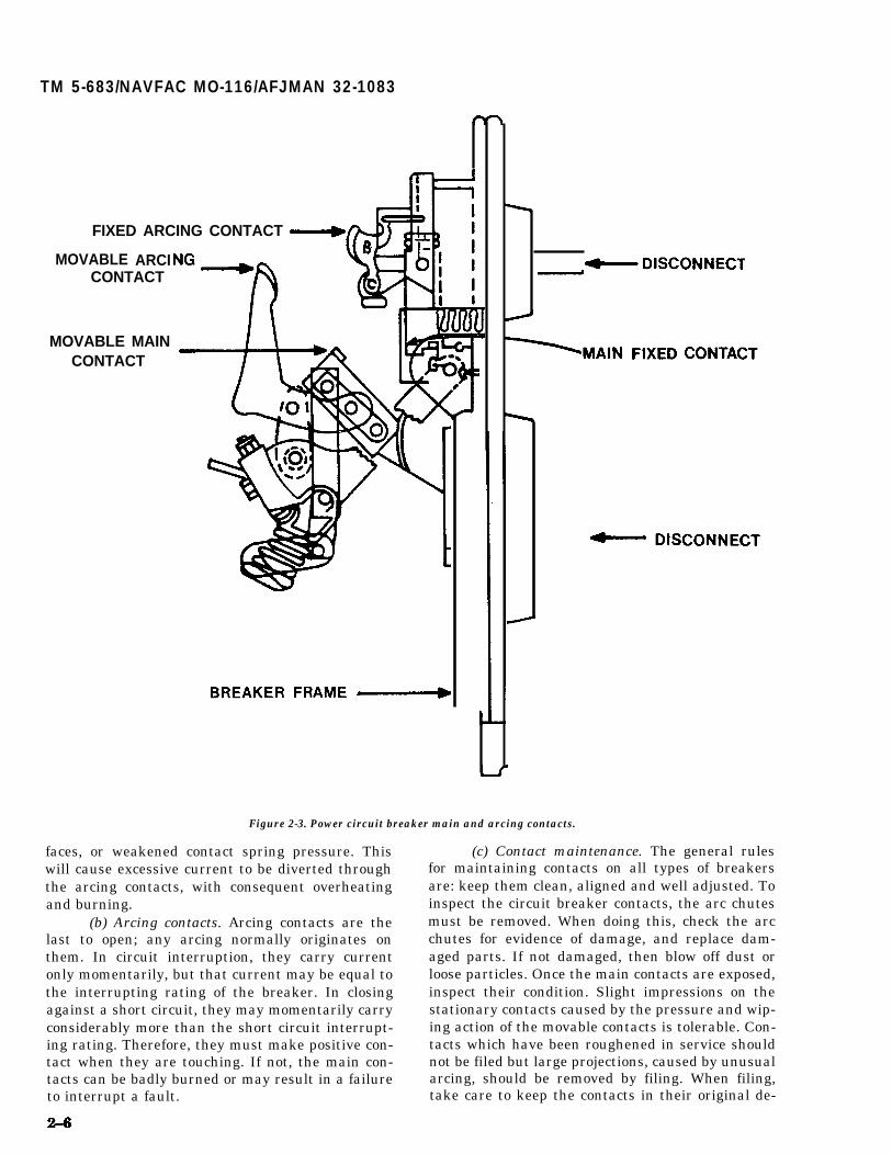
(2) Contacts. The major function of the powercircuit breaker depends among other things uponcorrect operation of its contacts. These circuitbreakers normally have at least two distinct sets ofcontacts on each pole, main and arcing (fig 2-3).Some have an intermediate pair of contacts whichopen after the main contacts and before the arcingcontacts.
(a) Main contacts. When the breaker isclosed, practically the entire load current passesthrough the main contacts. Also, short circuit cur-rent must pass through them during opening orclosing faulted lines. If the resistance on these con-tacts becomes high, they will overheat. Increasedcontact resistance can be caused by pitted contactsurfaces, foreign material embedded on contact sur-
TM 5-683/NAVFAC MO-116/AFJMAN 32-1083
FIXED ARCING CONTACT
MOVABLECONTACT
MOVABLE MAINCONTACT
ARCI
Figure 2-3. Power circuit breaker main and arcing contacts.
faces, or weakened contact spring pressure. This (c) Contact maintenance. The general ruleswill cause excessive current to be diverted throughthe arcing contacts, with consequent overheatingand burning.
(b) Arcing contacts. Arcing contacts are thelast to open; any arcing normally originates onthem. In circuit interruption, they carry currentonly momentarily, but that current may be equal tothe interrupting rating of the breaker. In closingagainst a short circuit, they may momentarily carryconsiderably more than the short circuit interrupt-ing rating. Therefore, they must make positive con-tact when they are touching. If not, the main con-tacts can be badly burned or may result in a failureto interrupt a fault.
for maintaining contacts on all types of breakersare: keep them clean, aligned and well adjusted. Toinspect the circuit breaker contacts, the arc chutesmust be removed. When doing this, check the arcchutes for evidence of damage, and replace dam-aged parts. If not damaged, then blow off dust orloose particles. Once the main contacts are exposed,inspect their condition. Slight impressions on thestationary contacts caused by the pressure and wip-ing action of the movable contacts is tolerable. Con-tacts which have been roughened in service shouldnot be filed but large projections, caused by unusualarcing, should be removed by filing. When filing,take care to keep the contacts in their original de-
TM 5-683/NAVFAC MO-116/AFJMAN 32-1083
sign. That is, if the contact is a line type, keep thearea of contact linear, and if ball type, keep the ballshaped out. Discoloration of silver-plated surfaces isnot usually harmful unless caused by insulatingdeposits. These deposits should be removed withalcohol or a silver cleaner. Whether cleaned or not,lubricate the main contacts by applying a thin filmof slow aging, heat resistant grease. All excess lubri-cant should be removed with a clean cloth to avoidaccumulation of dirt and dust. Under no circum-stances should the arcing contacts be lubricated.Where serious overheating is indicated by discolora-tion of metal and surrounding insulation, the con-tact and spring assemblies should be replaced inaccordance with manufacturer’s instructions. Whilecarefully closing the circuit breaker, check for
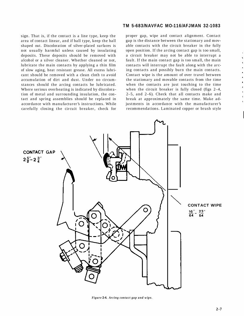
proper gap, wipe and contact alignment. Contactgap is the distance between the stationary and mov-able contacts with the circuit breaker in the fullyopen position. If the arcing contact gap is too small,a circuit breaker may not be able to interrupt afault. If the main contact gap is too small, the maincontacts will interrupt the fault along with the arc-ing contacts and possibly burn the main contacts.Contact wipe is the amount of over travel betweenthe stationary and movable contacts from the timewhen the contacts are just touching to the timewhen the circuit breaker is fully closed (figs 2–4,2–5, and 2–6). Check that all contacts make andbreak at approximately the same time. Make ad-justments in accordance with the manufacturer’srecommendations. Laminated copper or brush style
b
Figure 2-4. Arcing contact gap and wipe.
,,7
,
,
,
,
1
,
i
,
I1
CONTACT WIPE
2-7

TM 5-683/NAVFAC MO-116/AFJMAN 32-1083
ACRING CONTACTSTOUCHING
CON
Figure 2-5 Intermediate contact gap.
contacts found on older circuit breakers should bereplaced when badly burned. Repairs are not prac-tical because the laminations tend to weld togetherwhen burning occurs, and contact pressure andwipe are greatly reduced. These contacts may befiled to remove large projections or to restore theiroriginal shape. They should be replaced when theyare burned sufficiently to prevent adequate circuitbreaker operation or when half of the contact sur-face is burned away. Carbon contacts, used on oldercircuit breakers, require very little maintenance.However, inadequate contact pressure caused byerosion or repeated filing may cause overheating orinterfere with their function as arcing contacts.
(3) Operating mechanism. The purpose of theoperating mechanism is to open and close thebreaker contacts. This usually is done by linkagesconnected, for most power breakers, to a power op-erating device such as a solenoid or closing spring
2-8
for closing, and contains one or more small sole-noids or other types of electro-magnets for tripping.Tripping is accomplished mechanically, independentfrom the closing device, so that the breaker contactswill open even though the closing device still may bein the closed position. This combination is called amechanically trip-free mechanism. After closing,the primary function of the operating mechanism isto open the breaker when it is desired, which iswhenever the tripping coil is energized at above itsrated minimum operating voltage. The breaker op-erating mechanism should be inspected for loose orbroken parts; missing cotter pins or retaining keep-ers; and missing nuts and bolts. It should also beexamined for damage or excessive wear on cam,latch, and roller surfaces. Excessive wear usuallyresults in loss of travel of the breaker contacts. Itcan affect operation of latches; they may stick orslip off and prematurely trip the breaker. Adjust-

TM 5+583/NAVFAC MO-1 16/AFJMAN 32-1083
11
L 1 3“n———
CONTACT WIPE
16 32
Figure 2-6. Main contact wipe.
menta for excessive wear are possible for certain lubricate pins and bearings not disassembled. Use aparts. For others, replacement is necessary. The non-hardening and non-conductive grease to lubn-closing and tripping action of a breaker should be cate the ground or polished surfaces of cams,quick and positive. While documenting, operate the rollovers, latches and props, pins and bearings thatbreaker several times, checking for obstructions or are removed for cleaning. Check the breaker oper-excessive friction. Any binding, slow action, delay in ating mechanism adjustments and readjust as de-speration, or failure to trip or latch must be con- scribed in the manufacture% instruction book. Ifrected prior to returning to service. Clean and these adjustments cannot be made within specifiedrelubricate the operating mechanism. Use a tolerances, it will usually indicate excessive wearnondetergent light machine oil (SAE-20 or 30) to and the need for a complete overhaul.
2-9
TM 5-683/NAVFAC MO-116/AFJMAN 32-1083
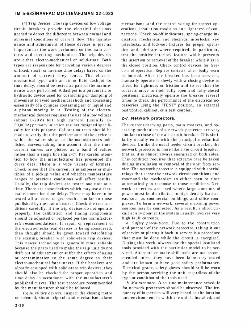
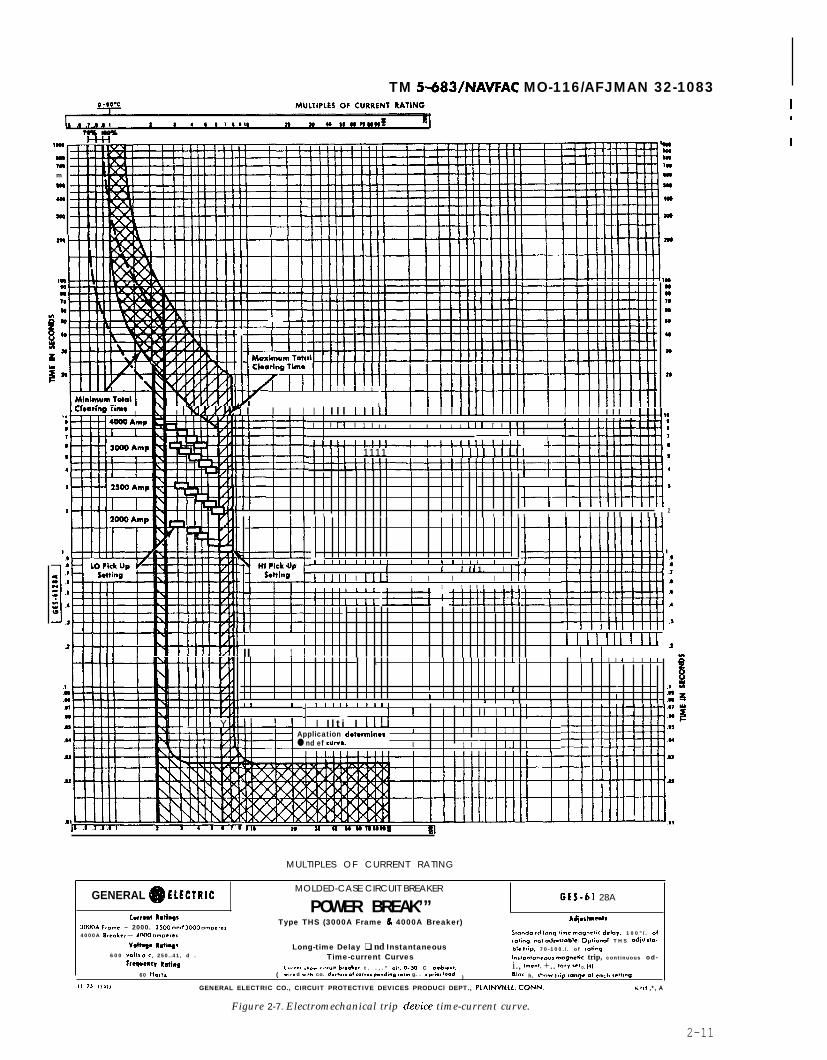
(4) Trip devices. The trip devices on low voltagecircuit breakers provide the electrical decisionsneeded to detect the difference between normal andabnormal conditions of current flow. The mainte-nance and adjustment of these devices is just asimportant as the work performed on the main con-tacts and operating mechanism. The trip devicesare either electro-mechanical or solid-state. Bothtypes are responsible for providing various degreesof fixed, short, or inverse time delays based on theamount of current they sense. The electro-mechanical type, with an air or fluid dashpot fortime delay, should be tested as part of the mainte-nance work performed. A dashpot is a pneumatic orhydraulic device used for cushioning or damping ofmovement to avoid mechanical shock and consistingessentially of a cylinder containing air or liquid anda piston moving in it. Testing of the electro-mechanical devices requires the use of a low voltage(about 0-20V) but high current (usually O-50,000A) primary injection test set designed specifi-cally for this purpose. Calibration tests should bemade to verify that the performance of the device iswithin the values shown on the manufacturer’s pub-lished curves; taking into account that the time-current curves are plotted as a band of valuesrather than a single line (fig 2–7). Pay careful atten-tion to how the manufacturer has presented thecurve data. There is a wide variety of formats.Check to see that the current is in amperes or mul-tiples of a pickup value and whether temperatureranges or previous conditions will affect results.Usually, the trip devices are tested one unit at atime. There are some devices which may use a ther-mal element for time delay. These may have to betested all at once to get results similar to thosepublished by the manufacturer. Check the test con-ditions carefully. If the trip devices do not operateproperly, the calibration and timing componentsshould be adjusted or replaced per the manufactur-er’s recommendations. If repair or replacement ofthe electro-mechanical devices is being considered,then thought should be given toward retrofittingthe existing breaker with solid-state trip devices.This newer technology is generally more reliablebecause the parts used to make the trip unit do notdrift out of adjustment or suffer the effects of agingor contamination to the same degree as theirelectro-mechanical forerunners. If the breakers arealready equipped with solid-state trip devices, theyshould also be checked for proper operation andtime delay in accordance with the manufacturer’spublished curves. The test procedure recommendedby the manufacturer should be followed.
(5) Auxiliary devices. Inspect the closing motoror solenoid, shunt trip coil and mechanism, alarm
2-10
mechanisms, and the control wiring for correct op-erations, insulation condition and tightness of con-nections. Check on-off indicators, spring-charge in-dicators, mechanical and electrical interlocks, keyinterlocks, and lock-out fixtures for proper opera-tion and lubricate where required. In particular,test the positive interlock feature which preventsthe insertion or removal of the breaker while it is inthe closed position. Check control devices for free-dom of operation. Replace contacts when badly wornor burned. After the breaker has been serviced,manually operate it slowly with a closing device tocheck for tightness or friction and to see that thecontacts move to their fully open and fully closedpositions. Electrically operate the breaker severaltimes to check the performance of the electrical ac-cessories using the “TEST” position, an externaltest/control cabinet, or a test coupler.
2-7. Network protectors.
The current-carrying parts, main contacts, and op-erating mechanism of a network protector are verysimilar to those of the air circuit breaker. This simi-larity usually ends with the principal mechanicaldevices. Unlike the usual feeder circuit breaker, thenetwork protector is more like a tie circuit breaker;that is, it is almost always energized on both sides.This condition requires that extreme care be takenduring installation or removal of the unit from ser-vice. The network protector is equipped with specialrelays that sense the network circuit conditions andcommand the mechanism to either open or closeautomatically in response to those conditions. Net-work protectors are used where large amounts ofpower must be distributed to high density load ar-eas such as commercial buildings and office com-plexes. To form a network, several incoming powersources may be connected. As a result, a short cir-cuit at any point in the system usually involves veryhigh fault currents.
a. Safety precautions. Due to the constructionand purpose of the network protector, taking it outof service or placing it back in service is a procedurethat must be done while the circuit is energized.During this work, always use the special insulatedtools provided with the particular model to be ser-viced. Alternate or make-shift tools are not recom-mended unless they have been laboratory testedand are known to have good safety performance.Electrical grade, safety gloves should still be wornby the person servicing the unit regardless of thetype or condition of the tools used.
b. Maintenance. A routine maintenance schedulefor network protectors should be observed. The fre-quency of inspection will vary based on the locationand environment in which the unit is installed, and
TM 5483/NAVFAC MO-116/AFJMAN 32-10831n
I109! r
m7nm
w,
490
m
Q80Dam1,8
999
8N
w
am
m
w
m
,..Hilla80
16
nn
e
m
ntttx—rmmtniI I 1 I I 1 1 1 I 1 1
1I Clwring Tim*
. . I KY I IWYM I I I I I I l l 11111 I I I I 1111 I 1111 I 1 I I I I l l I Ilu NI I II I 1 I I I I I I 1 1 1(1 [ I
t! iI
, , , I-1 !!!! -1--4-4--+ 4
I 1111 I I I I Ilul 1111 I
k=1 I
1 I
2 1 1I I I I I I I i I I I l l I I l t l
2t--t
ElHI Pick upS*ttlng
1 1 1 1 I i 1 1 1 , 1 1 , , 1 , , , , , ,
[ I I I I 1. I[1111 I 1111 1 I I I I I
1 1 I l l I I l lk 1 I c
1 1 1 I E#BTEH-tI
I 1 I 1 I 1 I
.2I I II Ill I Ill
I 1111 I II I 1 !1*
.1
.-
.8$
.m
.3sElililEilili1 LI 1 I I I I 1 I 1 1
8
1 1ii
:A[I
, , ! , - .08 z1 1 1 1 1 1 1 1 1 ,
1 I I I I I 11, :1111 Y I I l t i I 1111
Application dawmlnes I I I 1 1 1 I
● nd ef cuwa. I 1 I I II Ir ,
[ I I 1
j
.H
.W
.U
.U
mlnA-AE# ill.* I
I 19 n M a W
MULTIPLES OF CURRENT RATING
GENERAL ~ EIECTRICMOLDED-CASE CIRCUIT BREAKER
POWER BREAK’”GES-61 28A
Currmt R811wsType THS (3000A Frame & 4000A Breaker) AA@,lmemls
300QA From. – 2000. 25W end 3CQ0 .mpere,
4 0 0 0 A S,..4,, — iMO .“..,,, S!o.d. t6 long lime mqrwlk delw, 1 0 0 ” / . of
V.ltq* Rdiqs Long-time Delay ❑ nd Instantaneous,.a!;og. no! .d,.,1.ble. OpIi.n.l T H S .di. slo.
600 “.11, ..,, 250..41, d .bk Irip, 70-100. / . of ,4.9
Time-current CurvesFreqn.q h!i.~
1.s!..,....., mq.d. trip, continuous od-
(Cur.., ,ho. .ir<.i, br.oi.. t . . , . ” .;,, CL50 C o-b;..,.
)
i., h-,. +.. wv We O. HI
60 l+.,!. .,r. d .,!h co. d.d.., .1 (.r... dio~io~ roli. g. . . p.,., I.od. B1.a. h, $h... trip r..qe .1 each selling.
II 7J ,,&,, GENERAL ELECTRIC CO., CIRCUIT PROTECTIVE DEVICES PRODUCl DEPT., PLAINVILLC, CONN, .!,3 ,*, A
Figure 2-7. Electromechanical trip &vice time-current curve.
2-11
TM 5-683/NAVFAC MO-116/AFJMAN 32-1083
the number of operations the unit has made. In allcases, open the circuit first. This is done by movingthe control handle from “AUTOMATIC” to“MANUAL” and then manually opening the circuit.The control handle and/or operating mechanismshould then be locked in the “OPEN” position beforefurther work is done. Maintenance should includecleaning any accumulation of dust, dirt or corrosiondeposits, a thorough visual inspection, and overallperformance tests. Should the operation of any partbe suspect, refer to the manufacturer’s instructionsdescribing operation, adjustment, and replacementof these parts. If the network sensing relays are outof calibration, they should be recalibrated by com-petent shop personnel. The network protector ishoused in a cell or enclosure similar to those usedfor air circuit breakers (fig 2-8). The circuit breakermechanism and the network relay panel assemblyof a network protector are usually constructed aa anintegral, drawout unit which must be withdrawnfmm the housing for proper maintenance. Removalis done by unbolting the fuses at the top (usually)and the disconnecting links at the bottom (somemodels have bolt-actuated disconnecting fingers atthe bottom). After removing any additional lock-down bolts or latches, the drawout unit may becarefully withdrawn using the rails provided forsupport. Although this provides a comparativemeasure of safety, work should be done cautiously
since there is voltage present within the enclosure.It is better to move the unit completely away fromthe enclosure (fig 2–9). The following inspection andmaintenance operations can be done on the drawoutunit:
(1) Clean the breaker assembly. Use of avacuum cleaner is preferred. Use cloth rags free ofoil or grease for removing clinging dirt.
(2) Remove arc quenchers. Replace if damaged.(3) Inspect main contacts (fig 2-10). Smooth
any heavily frosted area with a very fine file or aburnishing stone which does not shed abrasive par-ticles. Protect hinged joints from falling particlesduring filing.
(4) File smooth any especially high projectionsof metal on arcing contacts.
(5) See that all electrical connections are tight.(6) Look for any abrasion of wire insulation
and repair.(7) Check for signs of overheating of control
wire and current carrying parts.(8) See that all springs are in good condition
and are properly seated in place.(9) See that all nuts, pins, snap rings or retain-
ers, and screws are in place and tight.(10) Replace any broken or missing barriers.(11) With the rollout unit still set aside, per-
form the following maintenance operations insidethe enclosure:
**WARNING**
Both source and load terminals are probably still energized. Use insulated tools and safetyprotective equipment for this work. Do not remove any barriers from the enclosure.
(a) Look for loose hardware on the enclosurebottom or beneath the frame. If any is found, traceto source and correct problem or replace.
(b) Clean stand-off bus insulators.(c) Remove oxide film from terminal contacts
if necessary.(12) Manually close and trip the breaker
mechanism according to instructions furnished forthe particular model.
(13) Perform an operational test using a net-work protector test kit.
(14) Conduct insulation resistance tests, di-electric test and electrical operating test in accord-ance with the manufacturer’s recommendations.
(15) Carefully replace the drawout unit in theenclosure. Make a final inspection to be sure nocontrol wiring has become snagged, and that noplugs or connecting surfaces have been bent or dam-aged.
2-8. Auxiliary switchgear equipment.
Auxiliary equipment includes devices such as fuses,capacitors, meters, relays, etc. This equipmentshould be serviced along with the major switchgearcomponents, unless there is some indication that adevice is being heavily or improperly used, in whichcase it should be inspected more often. Protectiverelays and meters should be inspected and cali-brated on a scheduled basis. Critical service equip-ment should have the protective relays checked atevery maintenance turn (annually or according tomanufacturer’s recommendations). Relays appliedto other general distribution circuits may be doneless frequently (see para 2-8h).
a. Fuses. Fuse maintenance is covered as a sepa-rate category of electrical equipment (para 5-4d).
b. Capacitors.power capacitor
The maintenance requirement oninstallations is so small that its
2-12

TM 5-683/NAVFAC MO-116/AFJMAN 32-1083
)INGs
BREAKER UNIT J COUPLING
Figure 2-8. Typical drawout network protector and enclosure.
Holes ForM o u n t i n g
Screws
( Two OnEach Side
Figure 2–9. Network protector removable unit.
importance is often overlooked. The voltage of thesystem at the capacitor location should be checkedat light load periods to determine if an overvoltagecondition exists. Any changes in circuit connections,which may increase voltage levels, warrant a re-
check of operating conditions. The conductor sizesshould provide for not less than 135 percent of ca-pacitor current at rated voltage and WA. As a gen-eral rule, if the side of the capacitor unit casing isoperating at a temperature above 55 degrees C (131degrees F a temperature almost too hot for bare-hand contact), then a more complete investigationof operating conditions should be made. The casetemperatures should never exceed 65 degrees C(149 degrees F) under any conditions. Adequateventilation is therefore necessary to remove theheat generated by continuous full-load duty. Re-move any obstructions at ventilation openings incapacitor housings to ensure that this ventilation ismaintained. A disconnected capacitor retains itselectrical charge for some time and may even retainthe full-line voltage across its terminals. Thereforealways discharge a capacitor before handling ormaking connections. An insulation short circuitjumper may be used for this purpose; however, itshould only be applied with full knowledge of thecircuit, and with the use of appropriate protectiveequipment. Power capacitors are generally providedwith individual fuses to protect the system in caseof a short circuit within the capacitor. In addition toa faulty capacitor, a fuse may be blown by an abnor-mal voltage surge. Check for blown fuses and re-place them with a type recommended by the manu-facturer. Do not remove fuses by hand until thecapacitor has been completely discharged. Clean thecase of a capacitor, the insulating bushings, and any
2-13

TM 5-683/NAVFAC MO-1 16/AFJMAN 32-1083
ARCQUENCHER
BLOWOUTCOIL
ARCQUENCHERSUPPORTINGSCREWS
SCREWS FORMOVABLEARCINGCONTACT
LOCKINGPLATE
FLEXIBLECONNECTION
STOP PINFOR MOVABLEARCINGCONTACT
CONTACTSUPPORT
CROSS BAR
UPPERCONTACT BAR
MOLDEDSUPPORTFOR ARCQUENCNER
INSULATION
STATIONARYARCINGCONTACT
MOVABLEARCINGCONTACT
UPPER MAINSILVERCONTACTS
STOP SCREW
MAINBRIDGINGCONTACTBLOCK
LOWERCONTACTBAR
Figure 2–10. Typical contact construction for a network protector.
connections that are dirty or corroded. Inspect the posed connections, and safety gear and tools mustcase of each capacitor for leaks, bulges, or discolora-tion. If any of these conditions exist, then replacethe capacitor (para 11–2).
c. Battery supplies. The control battery is such animportant item in switchgear operation that it mustbe given strict attention in the maintenance pro-gram. The battery charger plays a critical role sinceit supplies normal direct current (DC) power to thestation and maintains the batteries at a high levelof charge. The batteries, in addition to supplyingtemporary heavy demands in excess of the chargercapacity, serve as a back-up source to trip breakersupon loss of alternating current (AC) power. Failureof the charger or its AC supply transfers all DC loadto the batteries. Each battery cell electrolyte levelshould be checked. While a single cell may not pro-duce a serious shock hazard, when the cells areconnected in a battery bank, a severe shock hazardmay be possible. Also, there are usually many ex-
2-14
be used to the best degree of safety such as faceshields, acid/caustic resistant gloves, emergencyeyewash, etc. Electrolyte is the fluid contained ineach battery cell (fig 2–11). Low electrolyte levelsindicate too high a charging rate. In this case, the“float-voltage” setting of the charger should bechecked against the battery manufacturer’s recom-mendations. The specific gravity of the battery elec-trolyte should be taken using a hydrometer (para14-6). If the readings between battery cells varymore than fifty points on the hydrometer scale, thebattery probably has a bad cell which should bereplaced. If all cells read consistently low (within 50points), the battery should be fully charged and thebattery charger checked for proper operation. Thebattery top surface should be clean. Surface con-tamination can produce leakage currents thatpresent a drain on the charger and the battery. Ventholes in the cell caps should be open. Battery termi-

nal connections should be tight and free of corro-sion. If the terminal connections are corroded, theyshould be cleaned with bicarbonate of soda. Batteryterminals and cable ends should be cleaned thor-oughly. If stranded cable is used it is advisable tocut off the corroded end. If this is not possible, thestrands should be separated and cleaned internally.Any dust accumulation on the battery chargershould be blown off or wiped clean. Ventilationopenings should be clear of obstruction. Terminalconnections should be checked for tightness. All re-lays, lights or horns for indicating such abnormalconditions as grounds, loss of AC power supply, andhigh or low voltage should be checked to ensure thatthey are operating properly. During maintenanceoutages of the AC supply, there may be times whenit is necessary to provide a temporary supply to the
TM 5-683/NAVFAC MO-1161AFJMAN 32-1083
charger. While being charged, a battery producesand emits a mixture of hydrogen and oxygen gaseswhich is very explosive. Open flames or sparks mustnot be permitted in close proximity to the batteries.The room or compartment in which operating bat-teries are located should be well ventilated. Smok-ing should be prohibited in these rooms or compart-ments.
d. Instrument transformers. Instrument trans-formers are used to step down a current or voltagein order to operate a meter or a relay. Indoor-typeinstrument transformers are normally dry type, ex-cept potential transformers (PTs) which may be en-closed in compound-filled metal cases. The morecommon transformer constructions have the com-plete transformer molded into one solid mass withonly the terminals exposed.
I ** CAUTION** I
I Never open circuit the secondary winding of a current transformer while energized. To do somay result in component damage or personal injury. I
VENT AND ELECTROLYTEFILLING FUNNEL
NEGATIVE (-) TERMlNAL/
POSITPLATE
RUBBERSEPARAT
IVE -
OR
/POSITIVE (+) TERMINAL
ELECTLEVEL
ROLYTELINES
NEGATIVE PLATE
Figure 2-11. Large cell for a stationary battery.
2-15

TM 5-683/NAVFAC MO-116/AFJMAN 32-1083
(11) Verify connection of secondary PT leads byapplying a low voltage to the leads and checking forvoltage contribution at applicable devices.
(12) Check for PT secondary load with second-ary voltage and current measurements. Make sureload is less than volt amps (VA) of PT.
f. Metering. Most of the buildings in a typicalmilitary installation are unmetered. Meters (bothrecording and indicating), relays, and associatedequipment are usually part of a substation, maindistribution switchboard equipment, or specialequipment. Industrial shops and other buildings oc-casionally utilize kilowatt hour demand meters,power factor meters, ammeters, and voltmeters. Inan effort to determine whether the maintenance oroperation of these meters is adequate demands thatthe metering instruments be of the specified range,accurately calibrated, and adequately serviced. In-strument accuracy is always expressed in terms ofthe percentage of error at the full-scale point. Maxi-mum accuracy, consequently, is obtainable by keep-ing the rating as high on the scale as possible, andrequires a properly rated instrument. An instru-ment with an accuracy of 1 percent, with a scalereading of 100 divided into 100 divisions, is accurateto plus or minus one division. Hence, a reading of 20has a margin of error of plus or minus one division,which in this instance means that the true valuecould be between 19 or 21—an actual variation of 10percent. If the maximum indicating meter readingis less than 50 percent of the meter range, indicat-ing meters should be recalibrated, and ratchets anddials changed. How often an instrument is cali-brated depends on its use and the desired accuracy.If calibration standards and equipment are notavailable, instruments of nearly the same ratingmay be checked against each other. If wide discrep-ancies are noted, the suspect instrument should bechecked by a competent laboratory or returned tothe manufacturer. For many military establish-ments, the utility company will best perform thiswork. Take care to prevent entrance of dirt or lintinto an instrument because this dirt could hinderthe actuation of the instrument pointer. Clean theglass with a damp cloth because a dry cloth mayinduce a static charge on the glass and affect theinstrument reading. Breathing on a charged glassdischarges it. Never oil instrument bearings. Indi-cating demand and power factor meters should be
tested and recalibrated every 2 years. Single-phasewatt hour meters should be tested at least onceevery 5 years; self-contained polyphase watt-hourmeters every 2 years. Transformer watt-hourmeters on the secondary system (600 volts and be-low) should also be tested every 2 years; trans-former watt-hour meters on the primary systemevery year. Voltmeters and ammeters should be cali-brated at 2-year intervals.
g. Alarms. Alarms associated with transformerovertemperature, high or low pressure, circuitbreaker trip, accidental ground on an ungroundedsystem, cooling water flow or overtemperature, orother system conditions should be tested periodi-cally to assure proper operation.
h. Indicators. Circuit breaker “open-close” indica-tors can be checked during their regular mainte-nance. Ground indicator lamps for ungrounded elec-tric systems should be checked daily or weekly forproper operation. Other miscellaneous indicatorssuch as flow, overtemperature, excess pressure, etc.,should be checked or operated periodically to assureproper operation.
i. Protective relaying. While the application of cir-cuit protection as developed in a short circuit andcoordination study is an engineering function, as-surance that this designed protection remains inoperation is a maintenance responsibility. Applyingrelay settings and periodically testing them aremaintenance functions. Relays should be examinedto ensure the following:
(1) All moving parts are free of friction or bind-ing.
(2) All wiring connections are tight.(3) All contacts are free of pitting or erosion.(4) solenoid coils or armatures are not over-
heated.(5) Glass, covers or cases are not damaged.
j. For relay testing procedures, refer to chapter 14.The protective relay circuitry should also bechecked by closing the breaker in the test positionand while documenting, closing the contacts of eachprotective relay to trip the circuit breaker.
2-9. Switchgear trouble-shooting.
Table 2–2 provides detailed information regardingtrouble-shooting switchgear failures. Probablecauses along with recommended remedies are listedfor typical failures.
2-16
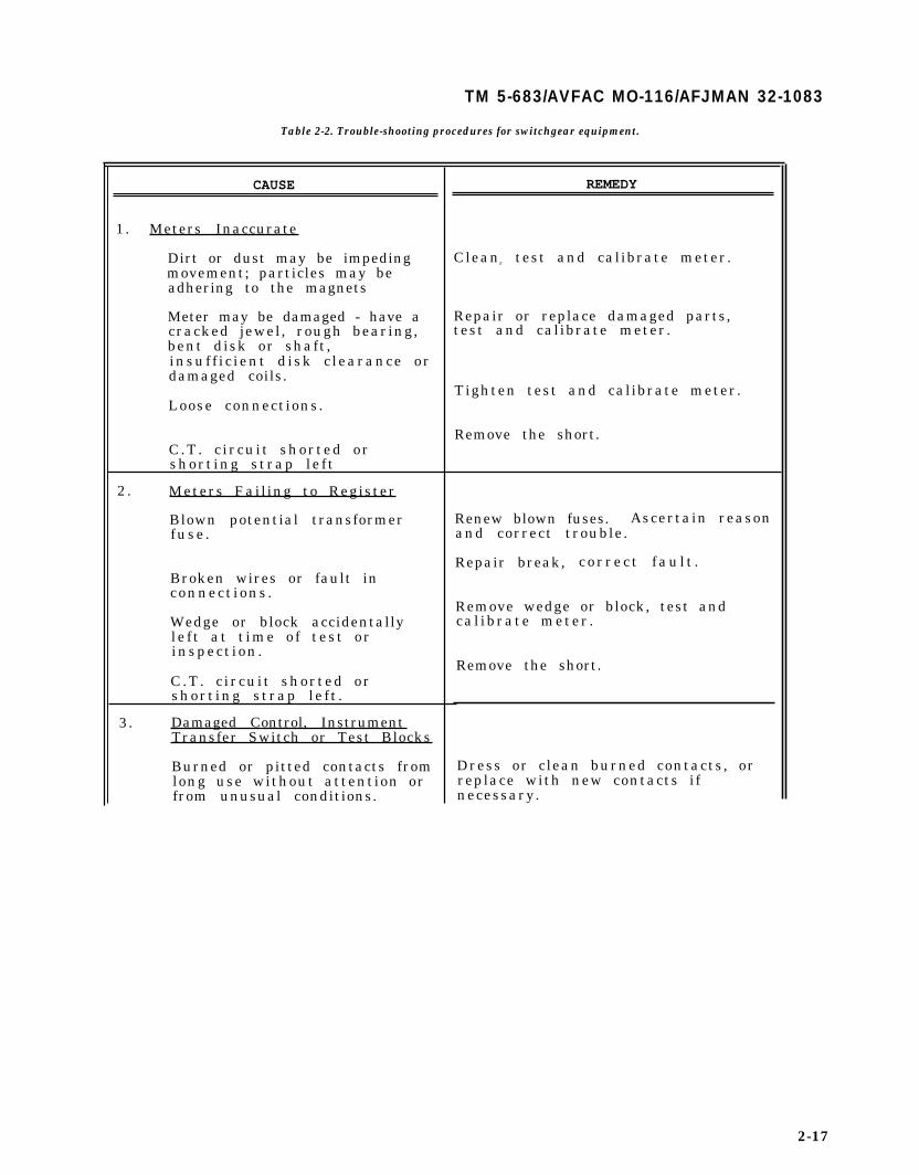
TM 5-683/AVFAC MO-116/AFJMAN 32-1083
Table 2-2. Trouble-shooting procedures for switchgear equipment.
CAUSE
1. Meters Inaccurate
Dirt or dust may be impedingmovement; particles may beadhering to the magnets
Meter may be damaged - have acracked jewel, rough bearing,bent disk or shaft,insuf f i c ient d isk c learance ordamaged coils.
Loose connections.
C.T. c i rcui t shorted orshort ing s trap le f t
2 . Meters Failing to Register
Blown potential transformerfuse .
Broken wires or fault inconnect ions .
Wedge or block accidentallyle f t a t t ime o f tes t orinspect ion .
C.T. c i rcui t shorted orshort ing s trap le f t .
3. Damaged Control, InstrumentTransfer Switch or Test Blocks
Burned or pitted contacts fromlong use without attention orfrom unusual conditions.
REMEDY
Cleanr test and calibrate meter.
Repair or replace damaged parts,test and calibrate meter.
Tighten test and calibrate meter.
Remove the short.
Renew blown fuses. Ascertain reasonand correct trouble.
Repair break, c o r r e c t f a u l t .
Remove wedge or block, test andcal ibrate meter .
Remove the short.
Dress or clean burned contacts, orreplace with new contacts ifnecessary.
2-17

TM 5-683/NAVFAC MO-116/AFJMAN 32-1083
Table 2-2. Trouble-shooting procedures for switchgear equipment - continued.
CAUSE
4. Relays Failing to TripBreakers
Improper setting.
Dirty, corroded or tarnishedcontacts .
Contacts improperly adjusted.
Open circuits or shortc i rcui ts in re lay connect ions .
Improper application of targetand holding coil .
Faulty or improperly adjustedtiming devices.
5. Noises Due to Vibrating Parts
Loose bolts or nuts permittingexcess ive v ibrat ion .
Loose laminations in cores oftransformers . reactors , e tc .
6. Connections Overheating
Increase of current due toadditional load that is beyondnormal current rating of barsor cab les .
Bolts and nuts in theconnect ion jo ints not t ight .
REMEDY
Adjust setting to correspond withc i r c u i t c o n d i t i o n s .
Clean contacts with burnishing tool.Do not use emery or sandpaper.
Readjust so that contacts close withproper amount of wipe.
Check with instruments to ascertainthat voltage is applied and thatcurrent is passing through relay.
Target and holding coils shouldcorrespond with tripping duty ofbreaker to assure proper tripping.
If t iming device is of bellows oro i l - f i l m t y p e , c l e a n a n d a d j u s t . I fo f induct ion-d isk type , check formechanical interference.
Tighten.
Tighten any loose nuts or coreclamps.
Increase the number or size ofconductors. Remove excess currentfrom c ircui t .
Tighten all bolts and nuts. Toomuch pressure must be avoided.
2-18

TM 5-683 /NAVFAC M-116/AFJMAN 32-1083
Table 2-2. Trouble-shooting procedures for switchgear equipment - continued.
CAUSE REMEDY
7 . Failure in Function of AllInstruments and Devices HavingPotential Windings
Loose nuts, binding screws or Tighten all loose connections orbroken wire at terminals. repair broken wire circuits.
Blown fuse in potential Renew fuses.transformer circuit.
Open circuit in potential Repair open circuit and check entiretransformer primary or circuits for intactness and goodsecondary. condi t ion .
Remove the short.C .T . c i rcui t shorted orshort ing s trap le f t .
8 . Breaker Fails to Trip
Mechanism binding or sticking Lubricate mechanism.due to lack o f lubr icat ion .
Mechanism out of adjustment. Adjust all mechanical devices, suchas togg les , s tops buf fers , openingspr ings , e tc . , according toinstruction book.
Examine surface of latch. If wornor corroded, it should be replaced.Check latch wipe and adjustaccording to instruction book.
Replace damaged coil.Damaged trip coil.
Replace blown fuse.Blown fuse in control circuit(where trip coils arepotent ia l type ) .
Repair faulty wiring. See that allFaulty connections (loose or binding screws are tight.broken wire ) in tr ip c i rcui t .
Fa i lu re o f l ack ing dev ice .
II
2-19

TM 5-683/NAVFAC MO-116/AFJMAN 32-1083
CHAPTER 3
TRANSFORMERS
3-1. Small power transformers
Transformers referred to herein are limited to thosehaving a primary voltage under 600V usually ofdry-type construction and are used for lighting, con-trol power, and small power applications. Thesesmall power transformers sometimes supply powerto loads where continuity of service is critical andtherefore a greater degree of attention is justified.While the percentage of transformer failures is low,failures that do occur are serious and result in ex-tensive downtime and expense. The best assuranceof continued high reliability is regular maintenanceprocedures. A transformer is a device usually usedto transform, or step down a higher distributionlevel voltage to a lower utilization level. Althoughamong the most reliable components in an electricalsystem, proper transformer maintenance is still anecessity. While removal of a transformer from ser-vice cannot always be accomplished, visual inspec-tions and testing can be performed with the trans-former in service. Transformers require very littleattention when compared to most electrical appara-tus. The extent of the inspection and maintenancewill be governed by the size, the importance of ser-vice community, the location on the system, andoperating conditions such as, ambient temperatureand the surrounding atmosphere. In general, a two-year maintenance cycle is appropriate (see para15-3 for transformers).
3-2. Dry-type transformers.
Dry-type transformers are of open-or-ventilatedtype construction with either air or gas serving asthe insulation medium.
a. Routine inspections. All measurements shouldbe taken at the time of peak load and recorded sothat a means of comparing existing versus previoustransformer conditions is available. Routine inspec-tions of dry-type transformers should include loadcurrent readings, voltage readings and ambienttemperature readings.
(1) Load current readings. If load current read-ings exceed the rated full load current of the trans-former, then steps should be taken to reduce theload to within design limits.
(2) Voltage readings. Either undervoltages orovervoltages can be detrimental to a load and/for thetransformer. If one of these conditions exists, thenits cause should be determined and corrected towithin nominal nameplate values.
(3) Ambient temperature readings. Dry-typetransformers are cooled by free circulation of sur-rounding air over their surfaces. In a totally en-closed transformer, all heat is transferred by theexterior surfaces; an encased transformer dependsupon air to enter the case at the bottom, flow up-ward over core and coil surfaces, and flow out of thecase at the opening near the top. These transform-ers will perform satisfactorily at rated output whensurrounding air does not exceed 40 degrees C (104degrees F) and adjacent structures permit freemovement of cooling air. Dry-type transformers aredesigned to reach rated temperature rise above am-bient air temperature when operating continuouslyat rated voltage, frequency, or load. Serious over-heating may result if the unit is operated for sus-tained periods at above rated voltage, above ratedcurrent, or at lower than rated frequency. Operatinga transformer above the recommended temperaturewill shorten the life of the solid insulation and sub-sequently increase the risk of a failure. Therefore,it’s important that ambient temperature readingsbe taken at the transformer to verify that it iswithin its design limits. If these limits are exceeded,simply moving the transformer to a cooler environ-ment or providing additional ventilation or remov-ing structures that prohibit the flow of cool airaround the transformer may correct overtempera-ture conditions. If these changes are not feasiblethen the load on the transformer needs to be re-duced or a higher rating transformer installed.
b. Special inspections. Before any work, more ex-tensive than a visual inspection is performed on atransformer, it must be de-energized, tagged andlocked-out (para 12–2). This is to ensure the safetyof both personnel and equipment. In general, dry-type transformers have no moving parts (fig 3–1).The only maintenance required is periodic tighten-ing of connections and removal of accumulated dust,dirt and lint as outlined below:
(1) Check for dirt accumulation on windings,internal leads and insulating surfaces.
(2) Check for dirt accumulation that impedesthe flow of cool air.
(3) Check for tracking and carbonization overinsulating surfaces.
(4) Check for cracked or loose insulators or coilspacers.
(5) Check deterioration of the turn insulationand barrier cylinders.
3-1
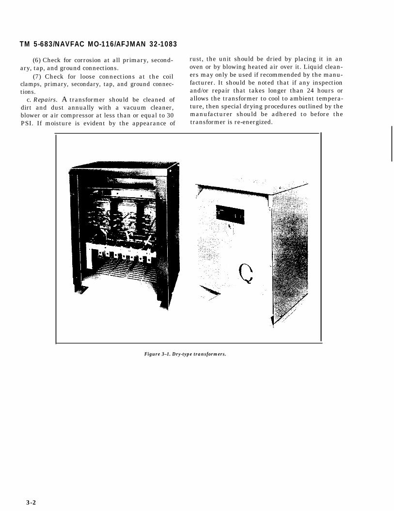
TM 5-683/NAVFAC MO-116/AFJMAN 32-1083
(6) Check for corrosion at all primary, second-ary, tap, and ground connections.
(7) Check for loose connections at the coilclamps, primary, secondary, tap, and ground connec-tions.
c. Repairs. A transformer should be cleaned ofdirt and dust annually with a vacuum cleaner,blower or air compressor at less than or equal to 30
rust, the unit should be dried by placing it in anoven or by blowing heated air over it. Liquid clean-ers may only be used if recommended by the manu-facturer. It should be noted that if any inspectionand/or repair that takes longer than 24 hours orallows the transformer to cool to ambient tempera-ture, then special drying procedures outlined by themanufacturer should be adhered to before the
PSI. If moisture is evident by the appearance of transformer is re-energized.
Figure 3–1. Dry-type transformers.
3-2

TM 5-683/NAVFAC MO-116/AFJMAN 32-1083
CHAPTER 4
ELECTRIC MOTORS
4-1. Maintenance of electric motors.
This information is intended to aid personnel con-cerned with the maintenance of electric motors. Thedata provided cover all DC and AC motors. Therecommendations are general in nature and nor-mally can be applied to the type of motors found onmilitary installations. They are not intended tocover in detail the specialized applications occasion-ally encountered. For such cases, the manufac-turer’s instructions should be followed. Periodic in-spection and regularly scheduled preventive main-tenance checks and services will enhance continu-ous operation of the equipment without unduebreakdowns. Frequency of these inspections oftendepends upon elements such as the criticality of theservice, hours equipment is normally in service, andenvironment under which the equipment operates.In order to ensure an accurate data base from whichan effective maintenance program can be initiated,a complete listing of machines in operation, thefunctions they perform and past history of operationand maintenance services must be maintained. Mo-tor inspection and scheduled maintenance in the AirForce is performed by the work center responsiblefor the system (HVAC, sewer plant, water plant,etc.). Preventive maintenance will generally involvelubrication, cleaning and checking for sparkingbrushes, vibration, loose belts, high temperature,and unusual noises. Repair work on larger motors isnormally limited to replacement or refinishing ofbearings, commutators, collector rings, brushes, etc.Motor rewinding should not be attempted by theinstallation support groups (Directorate of Engi-neering and Housing, Public Works or Civil Engi-neer Shops) since it is more economical to contractsuch work to commercial shops that specialize inmotor rewinding. With regard to the many thou-sands of fractional horsepower motors in operationthroughout the military services, it may be moreeconomical to replace a motor than to attempt torepair it. The local electrical supervisor must makethis determination. Table 4-1 can be consulted toaid in the selection of proper replacement motors.Special consideration should also be given to high-efficiency motors since they save both energy andmoney throughout the life of the motor. The follow-ing safety precautions should be observed whenworking on electric motors:
a. Make sure the machine is de-energized, taggedand locked out before starting work (para 12–2).
b. Personal protective equipment such asgoggles, gloves, aprons and respirators should beworn when working with hazardous substances(chap 11).
c. Great care should be exercised in selecting sol-vents to be used for a particular task.
d. Adequate ventilation must be provided toavoid fire, explosion, and health hazards wherecleaning solvents are used.
e. A metal nozzle used for spraying flammablesolvents should be bonded to the supply drum, andto the equipment being sprayed.
f. After tests have been made, discharge storedenergy from windings by proper grounding beforehandling test leads.
4-2. Alternating current (AC) motors.
AC motors should, with reasonable care, give longcontinuous service. However, there is a tendency toneglect motor maintenance and, as a result, motorfailures are frequent and repairs may become acontinuous and costly process. It is therefore recom-mended that a preventive maintenance program beestablished to minimize emergency breakdowns.The program should be supported with an effectivespare parts stock to speed up any unscheduled out-ages that may occur.
a. Squirrel-cage induction unit. This AC motor isthe most prevalent in use at military installations(fig 4-l). The squirrel-cage motor is the most rug-ged and the least expensive of all types of inductionmotors. The squirrel-cage motor is nearly a constantspeed machine. Typically its speed varies 0–5 per-cent from synchronous speed from no load to fullload. The basic design of the rotor can be modified toprovide a limited degree of external speed control.
b. Wound-rotor induction unit. This AC motor hasconnected to its collector rings the insulated phasewindings on the rotor (fig 4-2). Through stationarybrushes in contact with the collector rings, any de-sired value of external resistance may be added tothe secondary (rotor) winding to give greater speedcontrol of the motor. Also, use of external resistanceallows the motor to deliver a high starting torquewith a relatively small inrush current.
c. Synchronous unit. This type of AC motor (fig4–3) has an insulated winding in both the rotor andthe stator. A variable source of DC excitation issupplied to the rotor winding and an AC line sourceis supplied to the stator winding. A synchronousmotor is a constant speed machine with similar
4-1

TM 5-683/NAVFAC MO-116/AFJMAN 32-1083
Table 4-1. Motor application guide.

TM 583/NAVFAC MO-116/AFJMAN 32-1083
Table 4-1. Motor application guide--continued.

TM 5-683/NAVFAC MO-116/AFJMAN 32-1083
,
Table 4-1. Motor application guide - continued.

a
TM 5-683/NAVFAC MO-116/AFJMAN 32-1083
Table 4–1. Motor application guide - continued.
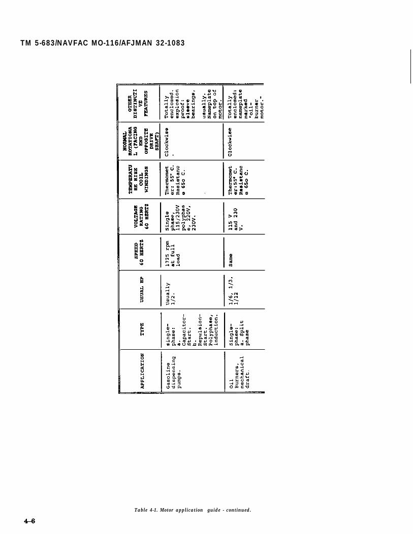
TM 5-683/NAVFAC MO-116/AFJMAN 32-1083
Table 4-1. Motor application guide - continued.

TM 5-683/NAVFAC MO-116/AFJMAN 32-1083
Table 4-1. Motor application guide - continued.

TM 5-683/NAVFAC MO-116/AFJMAN
GREASE FITTINGSAND
GREASE RELIEF PLUGS
32-1083
OOLI N
CONDUIT BOX
Figure 4–1. Cutaway view of squirrel-cage induction motor.
torque limitations. It may be used for power factorimprovement since a synchronous motor operates atunity or a leading power factor (in addition to lag-ging power factor). They are also more efficient thansome induction or DC motors having the samespeed and power rating. But the higher cost, largersize per horsepower and lower starting torque arethe disadvantages that limit synchronous unit ap-plication.
d. High-efficiency unit. This motor is specially de-signed to reduce electrical losses as much as 50percent so that less electricity is used over the en-tire life of the motor. These motors also operate athigher power factor values which help avoid powerfactor penalties and reduce the cost of power factorcorrection. They can deliver longer service, are morereliable, and are more easily maintained than nor-mal efficiency motors.
e. Components of AC machines. Maintenance op-
EAL
erations on an AC motor will encompass mainte-nance on the following components.
(1) Stator and rotor windings. The primaryparts of a typical motor are (fig 4–4): the frame andbase that support the assembled motor; the statorwhich is the stationary part consisting of an ironcore and insulated windings; and the rotor which isthe rotating element. The term armature is oftenused in lieu of rotor, particularly with DC motorsand for AC motors with commutators or collectorrings and brushes. Most stator and rotor problemscan be traced to winding failures. The life of a wind-ing depends upon keeping it as near to its originalcondition as long as possible. Insulation failurecauses immediate outage time. The following pointsshould be carefully examined and corrective actiontaken during scheduled inspections to prevent op-eration failures.

TM 5-683/NAVFAC MO-116/AFJMAN 32-1083
a b
Figure 4-2. Cutaway View of Wound-Rotor Induction Motor: a) Housing, b) Roto Assembly,c) Slip Ring Brushes, d) Stator Windings, 3) Ball Bearings.
(a) Cleaning motor windings. Dust and dirtare almost always present in windings that havebeen in operation under average conditions. Dustcombined with high humidity becomes highly con-ductive. It may break down the winding insulationand short circuit the motor windings. Frequentcleaning and drying may be necessary. Removingdry dirt with a clean, dry cloth is usually satisfac-tory if the apparatus is small and the surfaces to becleaned accessible. Do not use any material thatwill leave lint, for lint will adhere to the insulationand collect even more dirt. For removal of loosedust, dirt and particles, vacuum cleaning is pre-ferred rather than blowing out with compressed airsince there is less possibility of damage to the insu-lation and less chances of conductive or abrasiveparticles getting into areas that may cause damageduring motor operation. Where dirt cannot be vacu-umed, compressed air blowing may be used. How-ever, care should be taken that the dirt is not blownout of one machine into another. Air pressure shouldnot be greater than 30 psi. The air should be dryand directed in such a manner as to avoid furtherclosing ventilation ducts and recesses in insulation.Goggles or face shield should be worn when usingcompressed air to clean motors. Accumulated dirtcontaining oil or grease requires cleaning with asolvent. The solvent should be as recommended by
the manufacturer. A rag, barely moistened (not wet)with a nonflammable solvent, may be used for wip-ing. Avoid liquid solvent spraying which can carryconductive contaminants into critical areas and con-tribute to short circuits and grounds. Apparatuswhich has been clogged with mud from dust storms,floods or other unusual conditions, will require athorough water washing. Usually, a hose at pres-sures not exceeding 25 psi is used. After cleaning,the surface moisture should be removed immedi-ately to keep the amount of water soaked up by theinsulation to a minimum. Silicone-treated windingsrequire special treatment, thus the manufacturershould be contacted for advice.
(b) Drying motor windings. If after cleaning,storing or shipping, tests indicate that the windinginsulation resistance is below a safe level (para4-5), then the motor should be dried before beingplaced in operation. Two general drying methodscommonly used are external or internal heat. Exter-nal heat is preferred since it is the safer application.When forced air is used (fig 4-5), it may be heatedelectrically or by steam. This method is usually in-efficient and costly unless built into the originalinstallation. Electrical space heaters or infraredlamps may be used. They should be distributed soas not to overheat the insulation. Coil insulationmay be dried by circulating current through the
4-9

TM 5-683/NAVFAC MO-116/AFJMAN 32-1083
Figure 4-3. Cutaway view of synchronous motor.
EndShield
Figure 4-4. Primary parts of an AC induction motor.
4-10

Figure 4-5 Cleaning and drying motors in place.
winding. However, there is some hazard since theheat generated in the inner parts is not readilydissipated. This method should be followed only un-der competent supervision. For synchronous mo-tors, the “short circuit method” is sometimes used.This method is achieved by shorting the armaturewindings, driving the rotor and applying sufficientfield excitation to give somewhat less than full loadarmature current. Once the drying process has beencompleted, insulation testing of the motor windingis recommended to determine whether the insula-tion has been properly reconditioned. If a motormust continue to operate in a damp environment,then special enclosures are necessary to limit theeffects of a moist atmosphere.
(c) Inspecting motor windings. Check wind-ing tightness in the slots or on the pole pieces. Onecondition which hastens winding failure is move-ment of the coils due to vibration during operation.Check insulation surfaces for cracks, crazing, flak-ing, powdering, or other evidence of need to renewinsulation. Usually under these conditions, whenthe winding is still tight in the slots, a coat or two ofair-drying varnish may restore the insulation to asafe value. Check the winding mechanical supportsfor insulation quality and tightness, the bindingring on the stator windings, and the glass or wire-wound bands on rotating windings. Examinesquirrel-cage rotors for excessive heating or discol-ored rotor bars which may indicate open circuits orhigh resistance points between the end rings and
TM 5-683/NAVFAC MO-116/AFJMAN 32-1083
rotor bars. The symptoms of such conditions areslowing down under load and reduced startingtorque. Repairs to cast aluminum rotors with openbars are not feasible and such rotors have to bereplaced. Copper bar rotors can usually be repairedby rebrazing the joints.
(2) Bearings. The bearings are the most criticalmechanical part of a motor. To assure maximumlife, bearings should be subjected to careful inspec-tion at scheduled intervals. The frequency of inspec-tion is best determined by a study of the particularmotor operating conditions. Bearings are subject tometal fatigue and will eventually wear out eventhough they are correctly applied, installed andmaintained. Fatigue failures are characterized byflaking of the race surfaces along the ball or roller.Fatigue is a gradual process, which is dependentupon load and speed and usually is made apparentin its early stages by an increase in the operatingtemperature, vibration or noise level of the bearing.Bearing failures not attributed to fatigue failure areusually classified as premature. The majority ofthese premature failures are caused by the fol-lowing: incorrect bearing type; misalignment of themotor or load; misalignment or improperly installedbearing; rusting during storage; preloading or im-proper end-play adjustment; excessive thrust or ra-dial force; axial indentations; improper lubricationand entrance of contaminants into bearing. Followmanufacturer’s instructions and use lubricants asspecified. When using greases, store in clean con-tainers, handle with clean paddles or use a greasegun and keep containers covered. Do not overfillbearing housings. Overfilling contributes to heatbuild-up, damaged seals, leaks and collecting ofdirt. Overheating is particularly true of bearingsrunning at high speeds. Machines that are normallyidle for long periods should be exercised on a sched-uled basis. Exercising will keep the oil circulated,reduce condensation within the housing and lessenthe chances of flat spots developing on the bearingraces, balls or rollers. Inspect seals and vents regu-larly. Periodic maintenance services of bearings in-volves keeping a bearing dry, covered, clean andlubricated as well as checking operating tempera-ture. A clean bearing is particularly critical becausedirt means damage. It is therefore important toremember the following when cleaning bearings (fig4-6):
(a) Work with clean tools in clean surround-ings. Do not use wooden mallets, dirty, chipped orbrittle tools, or work on rough or dirty bench tops.
(b) Remove all dirt from the housing beforeexposing the bearings and take care to prevent loosedirt from getting into the housing.
4-11
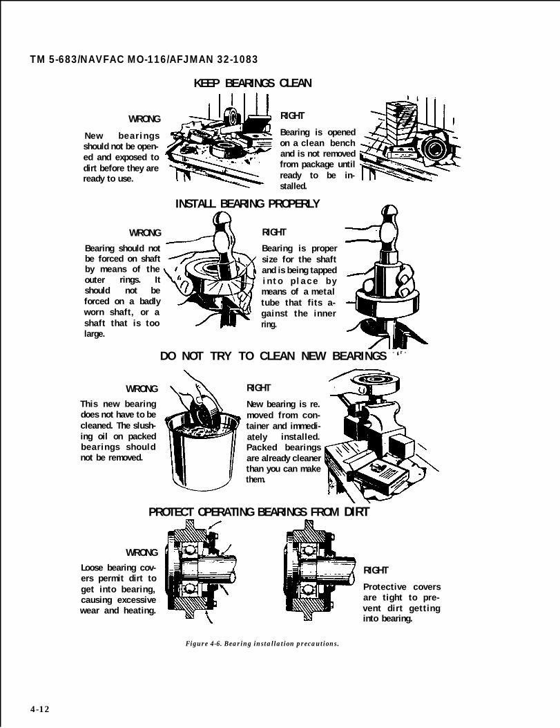
TM 5-683/NAVFAC MO-116/AFJMAN 32-1083
WRONG
New b e a r i n g sshould not be open-ed and exposed todirt before they areready to use.
WRONGBearing should notbe forced on shaftby means of theouter rings. Itshould not beforced on a badlyworn shaft, or ashaft that is toolarge.
KEEP BEARINGS CLEAN
RIGHT
Bearing is openedon a clean benchand is not removedfrom package untilready to be in-stalled.
INSTALL BEARING PROPERLY
RIGHT
Bearing is propersize for the shaftand is being tappedi n t o p l a c e b ymeans of a metaltube that fits a-gainst the innerring.
DO NOT TRY TO CLEAN NEW BEARINGS - ‘ r -
WRONGThis new bearingdoes not have to becleaned. The slush-ing oil on packedbearings shouldnot be removed.
RIGHT
New bearing is re.moved from con-tainer and immedi-ately installed.Packed bearingsare already cleanerthan you can makethem.
PROTECT OPERATING BEARINGS FROM DIRT
WRONGLoose bearing cov-ers permit dirt toget into bearing,causing excessivewear and heating.
RIGHT
Protective coversare tight to pre-vent dirt gettinginto bearing.
Figure 4-6. Bearing installation precautions.
4-12

TM 5-683/NAVFAC MO-116/AFJMAN 32-1083
(c) Handle bearings with clean, dry hands inconjunction with a clean, lint-free rag. This willlimit the chance of corrosion due to perspiration.
(d) Handle a reusable bearing as carefully asa new one.
(e) Use approved solvents and oils for flush-ing and cleaning. Apply fire-preventive precautionsif the solvent or oil is flammable.
(f) Lay bearings out on clean paper. Keepbearings wrapped in oil-proof paper when not inuse.
(g) Protect disassembled bearings from dirtand moisture.
(h) Do not spin uncleaned bearings. Rotatethem slowly while washing. A bearing should not bejudged good until inspected after cleaning.
(i) Do not spin any bearing with compressedair
(j) Soak bearings thoroughly in plenty of sol-vent. Then rinse them in a separate clean containerof clean solvent. Once cleaned, inspect the bearingsurfaces for nicks or scratches;. broken or crackedrings, separators, balls, or rollers; and discolored,overheated bearings. If the bearing is to be reusedin a short time, dip it in rust preventive, wrap ingrease-proof paper and store. For longer storage,coat all bearing surfaces with a light protectivegrease, wrap in grease-proof paper and store.
(k) Clean the inside of the housing beforereplacing bearings.
(l) Keep bearings in their original carton un-til ready for use if they are new. Do not wash the oilor grease out of a new bearing. Do not disassemblenew bearings.
(m) Install bearings properly after cleaning.(3) Ball and roller bearings. External inspec-
tion of ball and roller bearings (fig 4-7) at the timeof greasing will determine whether the bearings areoperating quietly and without undue heating.Equipped with a grease chamber, they can be veryeasily overgreased. Overgreasing may be preventedby opening the grease relief plug (fig 4-8) aftergreasing has been completed and running the mo-tor. When excess grease has drained through therelief plug, secure the plug.
Since ball bearings are often sealed, they requirelittle maintenance but it is very important that thegrease be kept clean. This also applies to sealedhousings (with the exception of permanently sealedbearings) which should be cleaned and regreasedevery 2 years or as recommended by the manufact-urer. The bearing housings may be opened to checkthe condition of the bearings and lubricant. If thelubricant must be changed, the bearing and housingparts should be thoroughly cleaned and new lubri-cant added. Special instructions regarding the type
or quantity of lubricant recommended by the man-ufacturer should be followed. In all cases, standardlubricating practices should be followed.
(4) Sleeve bearings. Sleeve bearings (fig 4-9)are most often used in fractional horsepower mo-tors. For older types of sleeve bearings, the oilshould be drained, the bearing flushed, and new oiladded at least every year. Newer sealed type sleevebearings require very little attention since the oillevel is frequently the only check needed for years ofservice.
(5) Insulation. Failure of insulation is anothermajor factor in motor breakdowns. Few types ofinsulation failures can be readily repaired. Insula-tion internal to the motor should be visuallychecked and defects further investigated. Heat isone of the principal causes of insulation failure in amotor. Make sure that the motor has adequate ven-tilation and that air openings are not obstructed.Also make sure that the motor is not overloadedwhich increases operating temperatures. Most mo-tors are equipped with thermal overload devicesapplied directly to the motor winding which meas-ure increases in temperature. At a predeterminedtemperature, the overload device will trip and dis-connect the motor from the circuit. When an over-load device has tripped, the operator should deter-mine the cause of overheating, correct it if possible,and reset the overload before restarting the motor(para 5-4e). An indication of the condition of theinsulation can be determined by performing an in-sulation resistance test (para 4-5).
4-3. Direct current (DC) motors.
On military installations, DC motors (fig 4-10) areused only if AC voltage is not available or wherethere is a wide range of speed control desired. Thereason for using a DC motor is often solely toachieve speed control. DC motor speed can be variedintentionally by varying the field current on shuntwound motors or by varying the input voltage toeither series or shunt motors. DC motors are classi-fied into different types based on the connection ofthe various windings. Shunt and series are consid-ered the two basic types of motors, as all others arederivatives of the two.
a. Shunt motors. The most widely used type ofDC motor is the shunt wound motor. As the nameimplies, these machines have the armature andfield circuits connected in parallel (shunt) to a con-stant source of voltage (fig 4-11a). While the term“shunt” is still used, relatively few motors are nowapplied in this way. Shunt motors as now appliedhave their field circuits excited by a source of powerthat is separate from the armature source of volt-age. The field excitation voltage level is usually the
4-13

TM 5483/NAVFAC M-l 16/AFJMAN 32-1083
Ball Bearing
Tapered Roller Bearing9EARING
F7
WIDTH
CUPCUP LENGTH
S T A N O O W
RADIUS~rOUTSIDE
D IAMETER
L
Straight Roller Bearing
R
Ball Thrust Bearing
t-
O UTSIDE D I A M E T E R
~ — - B o R E - j 1&~kR
~FACE l - SE P A R A T O R
Needle Roller Bearing
S H E L L-
I?CTAINIMGLIP
Figure 4-7. Construction of ball and roller bearings,
4-14

a.
c .
TM 5-683/NAVFAC M-116/AFJMAN 32-1083
d .
I .
e .
Figure 4-8. Greasing Bearings: a) Wipe away dirt from fitting or plug, b) Remove lower plug, C) Catch any run-out,d) Add new grease, e) Run motor and allow excess grease to escape, f) Install and tighten lower plug.
same as the armature voltage, however, special fieldvoltage ratings of 15 to 600 volts are available forapplication as a modification. The shunt motor ischaracterized by its relatively small speed changeunder changing load.
b. Series motors. As the term implies, series mo-tors have their field windings connected in serieswith the armature circuit, therefore, it carries fullmotor current (fig 4-11b). Series connection results
in a characteristic whereby motor speed is a func-tion of load. Thus, the series motor is a variablespeed motor.
c. Compound motors. A motor which is built withboth shunt and series fields is termed a compoundwound motor (fig 4–11c). By proportioning the rela-tive amounts of series and shunt windings, the de-signer may shift the motor characteristics to bemore nearly shunt or more nearly series in nature.
4-15

TM 5-683/NAVFAC M-116/AFJMAN 32-1083
Figure 4-9. Typical sleeve bearings.
Figure 4–10. Cutaway views of a typical DC motor
4-16

TM 5-683/NAVAC MO-116/AFJMAN 32-1083
FIELD
[ F l ]- [ F2]
ARMATURE
[A1] [A2][+] [-] v s o u c e
a.
[ A 2 ] [ S 2 ]
ARMATURE FIELD
[+] V S O U R C E [ - ]
b.
[ [ F l ] [F2] 1
I SHUNT FIELD ISERIES FIELD
[ A 2 ] [ S l ] [S2]
c .
Figure 4–11. Main Types and Connections of DC Motors: a)Shunt motor b) Series motor c) Compound motor
d. Components of DC machines. The basic operat-ing and maintenance requirements for DC motorsare similar to those for AC motors. There are somespecial requirements due to the peculiar construc-tion features of the DC motor. The recommenda-tions that follow, particularly those for the armat-ure (fig 4–12), also apply to AC synchronousmotors, It is important that the armature be keptclean. Dust, grease, corrosive gases, moisture andoil are particularly harmful.
(1) Field windings. The field is made up of aframe with field poles fastened to the frame’s innercircumference. The field windings, mounted on
laminated steel poles, furnish excitation for the mo-tor. Inspect field winding insulation and determineif they are dirty and oil-soaked. Check for malfunc-tioning controls which cause excessive field currentthat can cause excessive heating and failure. Othercauses of winding heating are excessive voltage, in-sufficient speed, off-neutral brushes, overloads andpartial short circuit in a field coil. Never run a DCmotor with the field circuit open. If the field wind-ing is open-circuited, the motor will fail to start orwill operate at excessive speeds at light loads, andexcessive sparking will occur at the commutator.Check the insulation resistance of the windings(para 4-5).
(2) Brushes. Maintenance and inspection ofbrushes should be performed regularly to ensurethe following (fig 4-13):
(a) Brushes are not loose in their holders.Replace worn brushes. NOTE: Replacementbrushes are of several types and grades. Successfulmotor operation depends upon proper selection ofthe replacement brush best suited for the servicerequirements of the motor.
(b) Brushes are not sticking in their holders.Clean brushes and holder.
(c) The tools and/or heels of the brush face arenot chipped or cracked. Replace brush if damaged.
(d) Brush shunt leads are properly attachedto the brushes and their holders. Replace brush ifshunt lead is loose at the brush. Tighten if lead isloose at the holder.
(e) Correct brush tension is maintained. Re-adjust the brush spring pressure in accordance withthe manufacturers’ instructions when adjustment isprovided. When adjustment is not provided, replacethe spring.
(f) Brush holder studs are not loose. Tighten,if loose.
(g) Brushes are not discolored. Brushesshould have a highly glazed or very dull finish.Clean the brushes when they become black or grey.
(h) Reset brushes at the correct angle.(i) Reset brushes in the neutral plane.(j) Properly space brushes on the commuta-
tor to 1/32 inch.(k) Correctly stagger the brush holders.(l) Properly space brush holders from the
commutator (usually l/16 to 3/16 inch.). If theproper spacing is not maintained, the brushes willride the surface of the commutator poorly. This isespecially applicable to the motor using an inclinedbrush holder since the brush will be shifted to theneutral position, leading to poor commutation.
(m) Check to ensure that the correct grade ofbrush, as recommended by the manufacturer, is be-ing used.
4-17

TM 5-683/NAVFAC MO-116/AFJMAN 32-1083
Figure 4-12. Armature of a large DC motor on stands.
Figure 4-13. Inspecting and installing brushes on a large DC motor.
4-18

(3) Commutators. A cutaway section of a com-mutator is shown in figure 4-14. The primarysource of unsatisfactory commutation is due tofaulty operating conditions. Therefore, the principalmaintenance function is that of keeping the commu-tator surface clean, concentric, smooth, and prop-erly undercut. Surfaces of the commutator barsmust be even and free of ridges so that the commu-tation is concentric, thus allowing any object heldagainst it to react as though it were held against asmooth surface cylinder. Inspection and mainte-nance methods are as follows:
(a) Check for indication of brush chatter (fig4-15). Brush chatter is most evident by chippedbrushes. This condition results from either a poorcommutator surface or high friction between thebrush and commutator. High friction is normallycaused by operating the motor under a light load,operating the motor under a load that exceeds thecommutator’s rated capacity for prolonged periodsor, film build-up on the commutator. Remediesare: increase the load; reduce the load; and, cleanthe commutator respectively.
(b) Check for threading or streaking (fig4-16). Threading or streaking of commutator sur-faces is characterized by fine lines inscribed around
BRUSH SURFACE RISER
TM 5-683/NAVFAC MO-116/AFJMAN 32-1083
the commutator. It results when copper particlestransfer to the face of the brush. These particles cutthrough the commutator film, creating areas whichcarry more than their share of current. They alsocause rapid wearing of the brushes and lead to com-mutator resurfacing. Use of natural graphitebrushes, which have cleaning action, cuts down onthe formation of film that hinders passing current.Maintenance personnel should check for any evi-dence of the lack of uniformity in brush action onthe commutator surface and film. Evidence of suchaction should be corrected as soon as possible.
(c) Check for sparking. Sparking often re-sults from poor commutation. This condition may beimproved by repositioning the brushes so that theyare slightly against rotation. When repositioningthe brushes that do not provide better commuta-tion, the commutating-pole air gap must be ad-justed.
(d) Check for flashing. Flashing normally re-sults from conditions that cause a sudden change inthe field strength of the motor’s current or voltage.Flashing can be prevented by frequent checks andelimination of conditions that contribute to short-circuiting.
ARMATURE COILCONDUCTORS
Figure 4-14. Cutaway section of a commutator.
4-19

TM 5-683/NAVFAC MO-116/AFJMAN 32-1083
Figure 4-15. Brush "Chatter" Action.
(e) Check film on commutator for even anduniform color (fig 4-17). The color should be be-tween light to dark brown. Clean the commutator asfrequently as required to maintain the proper color.
(f) Copper pickup from the commutator sur-face, indicated when copper fragments become em-bedded in the brush faces, constitutes a danger sig-nal and, unless corrected, becomes progressivelyworse. The condition can be corrected by providingproper bar-edge bevelling, sanding the brush faces,and thoroughly blowing out the motor after all otherwork has been completed.
(g) Check the commutator concentricity witha dial gauge (fig 4-18). A dial reading of .001 inch onhigh speed machines to several thousandths of aninch on low speed machines can be considered nor-mal. When evidence indicates that the commutatoris out of round or eccentric (fig 4-19), it can berestored by grinding” with a grinding rig. Whilegrinding, vacuum frequently to prevent copper andstone grindings from getting into the windings.Grinding should be performed only by experiencedpersonnel when the proper tools are available.
(h) After grinding the commutator, the micainsulation separating the copper segments must beundercut (fig 4-20). Bevel the edges of the bar andclean the commutator slots. Bevelling eliminatesthe sharp edge under the brush at the entering side.Again, follow the manufacturer’s instructions inthis repair function. Do not attempt this operationunless proper tools, instruments, and qualified per-sonnel are available.
4-20
(i) After conditioning a commutator, ensurethat it is clean of traces of copper, carbon, or otherdust.
4-4. Motor operating considerations.
Often problems that cause motor breakdown andpremature failure can be traced to inadequate con-sideration of operation and application of the motor.To enhance motor operation and improve longevityconsider application, type of motor, horsepower,speed, voltage rating and environmental conditions(table 4-1). The following paragraphs reiterate themajor causes of motor failures.
a. Dirt. Dirt can: plug ventilating spaces, inter-fering with proper cooling; glaze the faces of com-mutator brushes, resulting in harmfiul sparking;blanket windings, interfering with heat radiationand causing dangerous temperature rises; buildinto a hazard of shorting or grounding, if metallicparticles are present and, cause complete motorbreakdown.
b. Dust. In open-type motors, use every possiblemeans of keeping out dust. Under no conditionshould dust be allowed to come in contact with thebearings. Keep the oil-fill caps closed at all times;maintain the dust seals and gaskets in good condi-tion and replace them when worn. Keep plenty ofclean rags available for wiping off the motor hous-ings, cleaning commutators and removing dust fromwound sections. Vacuum loose dirt within the motor.If vacuum cleaning is not effective, blow out thewindings with dry compressed air at a pressure not

.
TM 5-683/NAVFAC MO-116/AFJMAN 32-1083
a.
b .
Figure 4-16. Poor Commutator Conditions: a) “Threading”, b) “Streaking”.
to exceed 30 psi. Greater pressure may loosen the air. These fumes quickly change the mass into aninsulation and blow dirt under it. If blowing or active destructive agent and a conductor of leakagevacuuming will not remove accumulated dirt, use currents. Moisture preventive measures are simplesolvents as recommended by the motor manufact- and therefore will not be discussed in detail. How-urer. ever, close attention to good housekeeping methods
c. Moisture. Moisture soaks into and softens is necessary. Open-type motors should not be ex-winding insulation until it is no longer adequate as.. . posed to intrusion of water from drip or splatter.an insulator. When moisture gets inside a motor, it Standby motors should be run for a short time atunites with dirt to form a sticky mass. This mass least once a week to guard against moisture conden-absorbs acid fumes and alkali fumes present in the sation during periods of idleness. Before using an
4-21

TM 5-683/NAVFAC MO-116/AFJMAN 32-1083
b.
Figure 4-17. Good Commutator Films: a) A light, mottledsurface, b) Heavy film of nearly uniform color.
air line to blow out motor windings, first check to besure that water has not condensed in the line.
d. Friction. Many motors fail because of excessivefriction. Oil in sleeve bearings adheres to the shaftand is dragged along by rotation, forming a lubricat-ing film that prevents friction. It is important to usethe right oil at the right time and not too much.Follow the manufacturer’s instructions. Do not add
4-22
Figure 4-18. Example of eccentric commutator.
INSULATION
J
Figure 4-19. Dial gauge to measure commutator concentricity.
new oil while the motor is running since it is easy toadd too much. Check the oil while the motor isstopped and, if required, add oil to the full level.Excess oil is apt to leak into the motor and causedamage such as:
(1) Deteriorate the mica-insulating segmentsbetween commutator bars.
(2) Foul the commutator bars.(3) Soak windings to the point where rewind-
ing may be the only way to prevent burnout break-down of the motor.

TM 5-683/NAVFAC MO-116/AFJMAN 32-1083
.
A. MICA PROPERLY UNDERCUT.B. UNDERCUTTING TOOL TOO NARROW, LEAVING
FIN AT ONE SIDE OF SLOT.C. UNDERCUTTING TOOL VERY NARROW, LEAVING
FINS AT BOTH SIDES OF SLOT.D. SLOT IMPROPERLY INDEXED. PART OF BAR CUT
AWAY AND FIN OF MICA LEFT.E. TOOL TOO WIDE. PART OF BAR CUT AWAY.F. UNDERCUTTING T00 SHALLOW. SERVICE LIFE
SHORTENS BEFORE NEXT UNDERCUTTING.G. UNDERCUTTING TOO DEEP. POCKET COLLECTS
CARBON AND COPPER DUST, SHORT-CIRCUITINGBARS.
Figure 4-20. Common undercutting mistakes.
e. Installation. One of the most important ing of 230 volts will give reasonable performanceantifriction precautions for motors with ball orroller bearings is to ascertain that the bearings areproperly installed. The inner race should be tightenough on the shaft to rotate with it, but not sotight as to cause frictional distortion. Ball or rollerbearings are normally lubricated with grease, andas in the case of oil lubricants mentioned above,apply grease in accordance with the manufacture'sinstructions.
f. Vibration. Excessive vibration can loosen vari-ous parts, break electrical connections, crystallizeportions of the metallic structure and contribute toan increase in frictional wear. Checks should bemade regularly to identify conditions that contrib-ute to vibration such as misalignment, settling ofthe foundation, heavy floor loading, and excessivebearing wear particularly when records indicate fre-equent motor failures. Check to determine whethervibration in the driven machine is being transmit-ted to the motor. Check that the motor is properlyapplied for a particular load. Check for excessivebelt or chain tension. The trouble may lie in thepush-apart effect inherent in spur gears. Check formotor-shaft oscillation resulting from a loose bear-ing. Check for loose motor-mounting bolts.
g. Applied voltages. For general purpose applica-tions, a range of five percent under to five percentover the nameplate voltage may be applied withsatisfactory results. A motor with a nameplate rat-
on: 220, 230 and 240-V systems. A motor with asingle voltage rating of 230V will probably overheatif run on 208V. Most manufacturers recognize thisproblem and build extra capacity into the windingsto give a dual or triple voltage rating on the name-plate, that is: 208/230/240 volts. There are somecases where motors fail due to low voltage. If agiven motor is fully loaded or slightly overloaded, itwill operate within its temperature limits for nor-mal voltages. For voltages 90 percent and less of thenameplate rating, the same motor will severelyoverheat. The motor will fail if the low voltage con-dition is applied for long periods of time. The impor-tant thing to remember is that, in the examplegiven above, a fully loaded motor must have 100percent of its nameplate conditions in order to de-liver 100 percent of its capacity. A motor that onlyneeds to deliver 80 percent of its nameplate horse-power rating will most likely survive a prolongedlow voltage condition resulting in a somewhathigher than normal temperature. This is sometimesreferred to as "service factor". Motor performanceguarantee is based on its nameplate rating and notthe system nominal voltage. The relationship be-tween the nominal and nameplate rating is shownin table 4-2.
h. Choice. There is usually some choice in thesubstitution of voltages for the motors and applica-tions shown in table 4-2. It is not necessary to
4-23

Table 4-2. Nameplate voltage ratings of standard induction motors.
TM 5-683/NAVFAC MO-116/AFJMAN 32-1083
Single-phase rotors 120240
Three-phase motors208240480600
2400416048006900
13,800
115230
200230460575
23004000
660013,200
(a) From ANSI/IEEE Std. 141-1984
“special order” rewinding repairs or replacementsfor general purpose work. There are some caseswhere substitution cannot be used. An exact voltagereplacement should be ordered if:
(1) The motor is known to be delivering 100percent or more, continuously.
(2) Motor has a duty rating other than “con-tinuous” or “24 hours”.
(3) Motor is marked, “special purpose”, or “se-vere duty” on nameplate.
(4) A non-standard voltage is shown and nohorsepower rating is given.
4-5. Motor insulation testing.
The electrical test most often conducted to deter-mine the quality of low voltage motor armature andwinding insulation is the insulation resistance test.There are other tests available to determine thequality of motor insulation, but they are not recom-mended for low voltage motor testing because theyare generally too complex or destructive. An insula-tion resistance test should be conducted on rotatingmachinery immediately following their shutdownwhen the windings are still hot and dry. A megohm-meter (para 13–4) is the recommended test equip-ment. It should be applied to armature and rotating
or stationary field windings. Before testing the mo-tor insulation, de-energize the circuit. Then discon-nect any potentially low insulation sources, such aslightning arresters, capacitors and other voltagesources. Lead-in cables or busses and line-side cir-cuit breakers or starters can be tested as a part ofthe circuit provided a satisfactory reading is ob-tained. Motor test connections for AC and DC mo-tors are shown in figure 4-21. If the insulationresistance is below the established minimum, thecircuit components should be tested separately toisolate the source of low impedance. All data shouldbe recorded and compared to previous periodic read-ings. Any persistent downward trend is an indica-tion of insulation trouble even though the valuesmay be higher than the recommended minimumacceptance values which are:
AC and DC motor (250V or less) 500,000 OHMSAC and DC motor (1OOOV or less) 1 MEGOHM
4-6. Motor trouble-shooting.
Tables 4-3, 4-4 and 4-5 provide detailed data ontroubleshooting motor breakdowns. Motor troublesalong with their probable cause(s) and recom-mended maintenance or corrective actions are alsogiven.
4-24

TM 5-683/NAVFAC MO-116/AFJMAN 32-1083
.
BRUSHES LIFTED OFF
rCOMMUTATOR
A.C.MOTOR
I
SOURCE
I - EART
- MAIN SWITCH
i I N S U L A T I O N
Figure 4-21. Connections for Testing Motor Insulation Resistance: a) (Top) connections for a DC motorb) (Bottom) connections for an AC motor.
4-25

TM 5-683/NAVFAC MO-1161AFJMAN 32-1083
Trouble
Motor will notstart
Motor noisy.
Table 4-3. AC induction motor trouble-shooting.
Probable Cause
Overload Control Trip
Power not connectedto motor.
Faulty (Open) fuses.
Low voltage.
Wrong conrolconnections.
Loose Terminal- leadconnction.
Driven machineLocked.
Open Circuit instator or rotorwindi ng.
Short c i rcui t instator winding.
Winding grounded.
Bearing Stiff.
Grease too stiff.
Faulty control .
Overload.
Failed startercapacitor.
Motor running singlephase.
Electr ical loadunbalanced.
Shaft bumping(sleeve-bearingmotors).
Maintenance
Wait for overload to cool. Try startingagain. If motor still does not start,check, all the causes as outlined below.
Connect power to control, check controlsequence and power to motor.
Check Connections.
Test fuses and circuit breakers.
Check motor-nameplate values with powersupply. Also check voltage at motorterminals with motor under load to be surewire size is adequate.
Check connections wi th control wir ingdiagram.
Tighten Connections.
Disconnect motor from load. I f rotor s tar tssatisfactorily, check driven machine.
Check for open circuits.
Check for shorted coil.
Test for grounded winding.
Free bearings or replace.
Use special lubricant for special conditions
Troubleshoot the control
Reduce Load
Isolate and discharge capacitor checkimpedance. If opened or shorted, replace.
Stop motor, than try to s t a r t . It will notstart on single phase.
Check for "openU in one of the lines orcircuits.
Check current balance.
Check aligmen t and condi t ion of bel t . Onpedestal -mounted bearing, check cord playand axial centering of rotor.
4-26

. .. ‘,-
.
TM 5-683/NAVFAC MO-116/AFJMAN 32-1083
Table 4-3. AC induction motor trouble-shooting-continued
Trouble
Motor vibrates.
At higher thannormal temperatureor smoking.
Probable Cause
Vibration fromunbalanced ormisalignment
Possible mechanicalsystem resonance.
Air gap not uniform.
Noisy ball bearings.
Loose punchings orloose rotor on shaft.
Rotor rubbing onstator.
Objects caughtbetween fan and endshields.
Motor loose onfoundation.
Coupling loose.
Overload.
Electrical Loadunbalanced.
Fuse blown, faulty,control, etc.
Restrictedventitation
Incorrect Voltage andfrequency
Motor stalled bydriven machine or bytight bearings.
Stator windingsorted.
Stator windinggrounded.
Maintenance
Balance or align machine.
Remove motor from load. If motoris st i l l noisy, rebalance motor.
Center the rotor and if necessaryreplace bearings.
Check lubricants. Replacebearings if noise is persistentand excessive.
Tighten all holdings bolts.
Center the rotor and replacebearings if necessary.
Disassemble motor end clean it.Any rubbish around motor should beremoved.
Tighten holding-down bolts. Motormay possibly have to be realigned.
Check coupling joint. Checkalignment. Tighten coupling.
Measure motor Loading with watt-meter. Reduce toad.
Check for voltage unbalance orsingle phasing.
Check for "openU in one of thelines or circuits.
Clean air passages and windings.
Check motor-nameptate values withpower supply. Also check voltageat motor terminals with motorunder full load.
Remove power from motor. Checkmachine for cause of stalling.
Use insulation testing procedures.
Use insulation testing procedures.
4-27

TM 5-683/NAVFAC MO-116/AFJMAN
4-28
Table 4-3. AC induction motor trouble-shooting-continued.
Trouble
At higher thannormal temperatureor smoking (Cont'd)
Bearings Hot
Sleeve Bearings hot.
Ball bearings hot.
Probable Cause
Rotor winding withLoose connections.
Belt too tight.
Motor used for rapidreversing service.
End shields loose ornot replacedproperly.
Excessive belttension or excessivegear side thrust.
Bent shaft.
Insufficient o i l .
Foreign material inoil or poor grade ofo i l .
Oil rings rotatingslowly or notrotat ing at a l l .
M o t o r titled too far.
Rings bent orotherwise damaged inreassembling.
Ring out of slot (oilr ing reta in ing c l ipout of place).
Defective bearings orrough shaft.
Too much grease
Wrong grade of grease
Insufficient grease.
Foreign material ingrease
Bearings misaligned
Maintenance
Tighten, if possible, or replacewith another rotor.
Remove excessive pressure o nbearings.
Replace with motor designed forthis service.
Make sure end shieds fit squarelyand are properly.
Reduce belt tension or gearpressure end real ign shafts . Seethat thrust is nott beingtransferred to motor bearing.
Straighten Shaft.
A d d oil - i f o i l supply is verylow - drain, f lush and ref i l l .
Dra in o i l , flush, and relubricateusing industrial lubricantrecommend by a reliable oilcompany.
Oil too heavy; drain and replace.
Oil ring has work spot; replacewith new ring.
Level motor or reduce tilt andrealign, if necessary.
Replace rings.
Adjust or replace retaining clip.
Replace bearings. Resurfaceshaft.
Remove relief plug and let motorrun. If excess grease doe notcome out, flush and relubricate.
Add proper grease
Remove relief plug and regreasebearing.
Flush bearings, relubricate; makesure that grease supply is clean.(Keep covered when not in use).
Align motor and check bearing-housing assembly. See that racesare exactly 90 degrees with shaft.

TM 5-683/NAVFAC MO-116/AFJMAN 32-1083
Table 4-3. AC indution motor trouble-shooting-continued.
Trouble
Ball bearings hot(cont’d. )
Wound rotor motortroubles
Motor runs at lowspeed with externalresistance cut out.
Excessive vibrationand noise.
Motor will not start
Probable Cause
Bearings damaged(corrosion, etc. )
Coupling loose.
Wires to control toosmall.
Control too far frommotor.
Open circuit in rotorcircui t ( includingcable to control).
Brushes sparking.
Dirt between brushand ring.
Brushes stuck inholders.
Incorrect brushtension.
Rough collectorrings.
Eccentric rings.
Open rotor circuit.
Current density ofbrushes too high(overload).
Ring threading
Faulty Connection.
Open circuit onephase.
Short circuitphase.
Vol tage fa l lslow.
one
too
Maintenance
Replace bearings.
Check coupling joint. Checkalignment. Tighten coupling.
Use larger cable to c o n t r o l .
Bring control nearer m o t o r .
Test to find open circuit andrepair.
Check for looseness, overload, ord i r t .
Clean rings and insulationassembly.
Use right size brush, cleanholders.
Clean brush tension and correct.
Sand and polish.
Turn in lathe or use portable toolto true up rings withoutdisassembling motor.
C o r r e c t o p e n connectons orcontrol.
Reduce load. (If brushes havebeen replaced, make sure they areof the same grade as originallyfurnished.
Low current density. Consultmanufacturer for different brushrecommendation.
I n s p e c t for open or poorconnect ion.
Test, locate and repair .
Open and repair.
Reduce the impedance of theexternal c i rcui t .
4-29
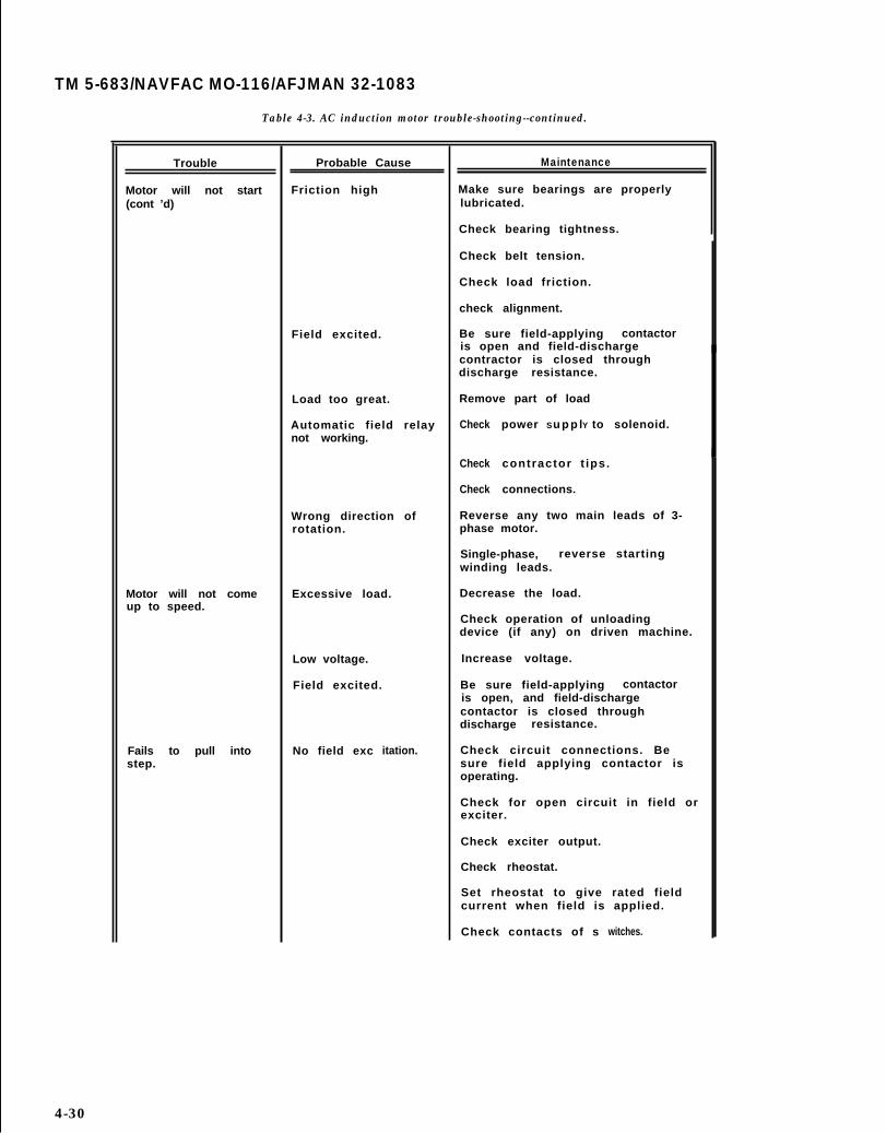
TM 5-683/NAVFAC MO-116/AFJMAN 32-1083
Table 4-3. AC induction motor trouble-shooting--continued.
Trouble
Motor will not start(cont ’d)
Motor will not comeup to speed.
Fails to pull intostep.
Probable Cause
Friction high
Field excited.
Load too great.
Automatic field relaynot working.
Wrong direction ofrotation.
Excessive load.
Low voltage.
Field excited.
No field exc itation.
Maintenance
Make sure bearings are properlylubricated.
Check bearing tightness.
Check belt tension.
Check load friction.
check alignment.
Be sure field-applying contactoris open and field-dischargecontractor is closed throughdischarge resistance.
Remove part of load
Check
Check
Check
power Su p p lY to solenoid.
contractor t ips.
connections.
Reverse any two main leads of 3-phase motor.
Single-phase, reverse startingwinding leads.
Decrease the load.
Check operation of unloadingdevice (if any) on driven machine.
Increase voltage.
Be sure field-applying contactoris open, and field-dischargecontactor is closed throughdischarge resistance.
Check circuit connections. Besure field applying contactor isoperating.
Check for open circuit in field orexciter.
Check exciter output.
Check rheostat.
Set rheostat to give rated fieldcurrent when field is applied.
Check contacts of s witches.
4-30

TM 5-683/NAVFAC MO-116/AFJMAN 32-1083
Table 4-3. AC induction motor trouble-shooting-continued.
Trouble
Fails to pull intostep (cont'd).
Motor pulls out ofstep or tripsbreaker.
Stator overheats inspots .
Field overheats.
Probable Cause
Load excessive
Inert ia of loadexcessive.
Exciter voltage low.
Open circuit in fieldand exciter circuit.
Short c i rcui t inf i e l d .
Reversed field spool.
Load fluctuateswidely.
Excessive torquepeak.
Power fails.
Line voltage too low.
Fluctuating load.
Rotor not centered.
Open phase.
Unbalanced currents.
Short c i rcui t in af i e l d c o i l .
Excessive fieldcurrent.
Maintenance
Reduce load
Check operation of loadingdevice (if any) on driven machine.
May be a misapplication - consultmanufacturer.
Increase excitation.
Examine exciter as shown in D. C.motors. Check field ammeter andits shunt to be sure reading isnot higher than actual current.
Locate and repair break.
Check with low voltage andpolarity indicator and r e p a i rf i e l d .
Check with lO w voltage andpolarity indicator and reverseincorrect leads.
See motor "hunts", below.
Check driven machine for badadjustment, or consult motormanufacturer.
Re-establish power circuit.
Increase if possible. Raiseexcitation.
Correct excessive torque peak atdriven machine or consult rotormanufacturer.
If driven machine is a compressorcheck valve operations.
Increase or decrease flywheelsize.
Try decreasing or increasing motorfield current.
Realign and shim stator orbearings.
Check connections and correct.
Loose connections; improperinternal connections.
Replace or repair.
Reduce excitat ion unt i l f ie ldcurrent is at nameplate value.
4-31
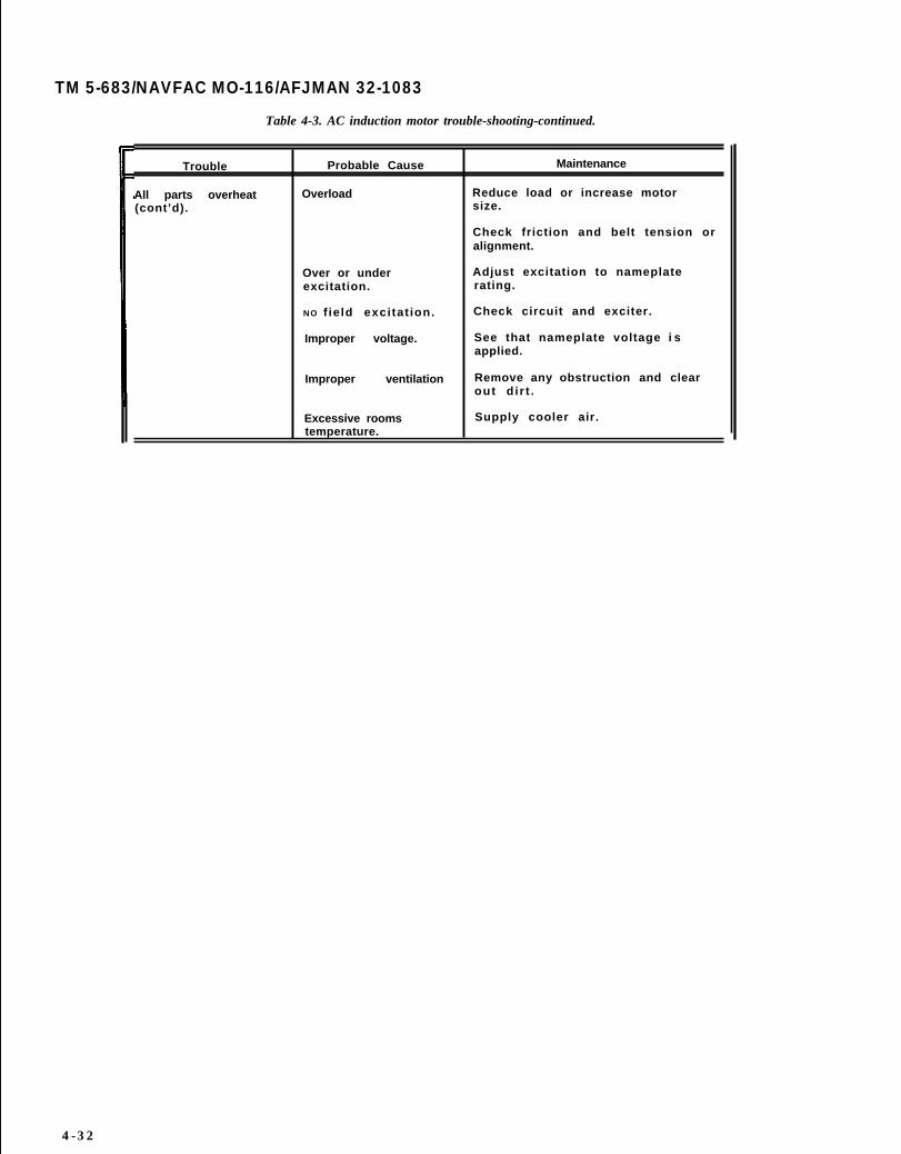
TM 5-683/NAVFAC MO-116/AFJMAN 32-1083
Table 4-3. AC induction motor trouble-shooting-continued.
Trouble Probable Cause Maintenance
All parts overheat Overload Reduce load or increase motor(cont’d). size.
Check friction and belt tension oralignment.
Over or under Adjust excitation to nameplateexcitation. rating.
NO f ie ld excitat ion. Check circuit and exciter.
Improper voltage. See that nameplate voltage i sapplied.
Improper ventilation Remove any obstruction and clearout d i r t .
Excessive rooms Supply cooler air.temperature.
4-32

TM 5-683/NAFAC MO-116/AFJMAN 32-1083
Trouble
Motor will notstart.
Motor will not comeup to speed.
Table 4-4. AC synchronous motor trouble-shooting.
Probable Cause
Faulty connection.
Open circuit onephase.
Short Circuit onephase.
Vol tage fal ls toolow.
Friction high.
Field excited.
Load too great.
Automatic field relaynot working.
Wrong direction ofrotation
Excessive load.
Low voltage
Maintenance
Inspect for open or poorcorrection.
Test, locate and repair.
open and repair.
Reduce the impedance of theexternal c i rcui t .
Make sure bearings are properlylubricated.
Check
Check
Check
Check
bearing tightness.
belt tension.
load f r ic t ion.
alignment.
Be sure field-applying contactoris open and field-dischargecontactor is closed throughdischarge resistance.
Remove part of load.
Check power supply to solenoid.
Check contactor tips.
Check connections.
Reverse any two main leads of 3- -
phase motor.
Single-phase, reverse startingwinding leads.
Decrease the load.
Check operation of unloadingdevice (if any) on driven machine
Increase voltage.
Be sure field-applying contactoris open, and field-dischargecontactor is closed throughdischarge resistance.
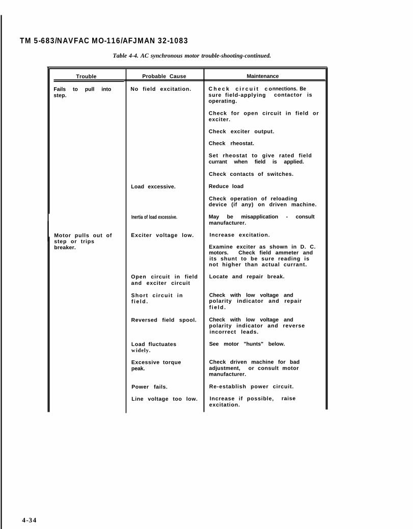
TM 5-683/NAVFAC MO-116/AFJMAN 32-1083
Table 4-4. AC synchronous motor trouble-shooting-continued.
Trouble
Fails to pull intostep.
Motor pulls out ofstep or tripsbreaker.
Probable Cause
No field excitation.
Load excessive.
Inertia of load excessive.
Exciter voltage low.
Open circuit in fieldand exciter circuit
Short c i rcui t inf i e l d .
Reversed field spool.
Load fluctuateswidely.
Excessive torquepeak.
Power fails.
Line voltage too low.
Maintenance
C h e c k c i r c u i t c onnections. Besure field-applying contactor isoperating.
Check for open circuit in field orexciter.
Check exciter output.
Check rheostat.
Set rheostat to give rated fieldcurrant when field is applied.
Check contacts of switches.
Reduce load
Check operation of reloadingdevice (if any) on driven machine.
May be misapplication - consultmanufacturer.
Increase excitation.
Examine exciter as shown in D. C.motors. Check field ammeter andits shunt to be sure reading isnot higher than actual currant.
Locate and repair break.
Check with low voltage andpolarity indicator and repairf i e l d .
Check with low voltage andpolarity indicator and reverseincorrect leads.
See motor "hunts" below.
Check driven machine for badadjustment, or consult motormanufacturer.
Re-establish power circuit.
Increase if possible, raiseexcitation.
4-34

TM 5-683/NAVFAC MO-116/AFJMAN 32-1083
Table 4-4 AC synchronous motor trouble-shooting-continued.
Trouble Probable Cause Maintenance
Motor "hunts”. Fluctuating load. Correct excessive torque peak atdriven machines or consult motormanufacturer.
If driven machine is a compressorcheck value operations.
Increase or decrease flywheelsize.
Try decreasing or increasing motorf ie ld current .
Stator overheats in Rotor not centered. Realign and shim stator orspots. bearings.
Open phase. Check Connections and correct.
Unbalanced currents. Loose connections: improperinternal connections.
Field overheats. Short c i rcui t in a Replace or repair.f i e l d c o i l .
Excessive field Redutce excitation until fieldcurrent. current is at nameplate value.
All parts overheat. Overload Reduce load or increase motorsize.
Check friction end belt tension oral igment.
Over or under Adjust excitation to nameplateexcitation. rating.
NO f ie ld excitat ion. Check circuit and exciter.
Improper voltage. See that nameplate voltage isapplied.
Improper ventilatiion. Remove any obstruction and cleanout dirt.
Excessive room Supply cooler air.temperature.
4-35

TM 5-683/NAVFAC MO-116/AFJMAN 32-1083
Table 4-5. DC motor or generator trouble-shooting.
Trouble
Motor will notstar t .
Motor starts, thenstops and reversesdirect ion ofrotation.
Probable Cause
Open circuit incontrol.
Low terminal voltage.
Bearing frozen.
Overload.
Excessive friction.
Brushes not down oncommtator.
Brushes worn out.
Brushes stuck inholders.
Power may be off.
Reverse polarity ofgenerator thatsupplies power.
Shunt and seriesfields are buckingeach other.
Maintenance
Check control for open in startingcircui t , open contacts, fuse orbreaker.
Check voltage with nameplaterating.
Recondition shaft and replacebearing.
Reduce load or use larger motor.
Check lubricaton in bearings tomake sure that the oil has beenreplaced af ter insta l l ing motor .
Disconnect motor from drivenmachine, and turn rotor by hand tosee if trouble is in motor .
Strip and reassemble motor; thencheck part by part for properlocat ion and f i t .
Stra ighten or replace bent orspring shaft (machines under 5hp).
Held up by brushreplacement.
Replace brushes.
Remove and sand,boxes.
springs, need
clean up brush
Check l ine connectons to starterwi th l ight .
Check contacts in starter.
Check generating unit for cause ofchanging polarity.
Reconnect either the shunt orseries field in order to correctthe polarity. Then connectarmature leads for desireddirect ion of rotat ion. The fieldscan be tried separately todetermine the direction ofrotation individually andconnected so that both give samerotation.
4-36

TM 5-683/NAVFAC MO-116/AFJMAN 32-1083
CHAPTER 5
MOTOR CONTROLS
5-1. Functions of motor controls.
The terms, controls, controllers, and starters areused interchangeably. The most common name forthe device that controls the operation of the motor isstarter. This name is not the best description of thedevice as the starter does much more than start themotor. It also stops the motor, it provides overloadand short circuit protection, and it disconnects themotor from the line after a period of overcurrent. Itmay also contain auxiliary devices that limit themotor inrush current, torque, and/or speed. Addi-tional protection features may include undervolt-age, phase reversal, and/or field loss.
5-2. Types of motor controls.
Some of the more common motor starters are de-scribed in this chapter beginning with the elemen-tary document starter and ending with the morecomplex adjustable speed frequency starter.
a. Document across-the-line starters. Documentstarters are most often used on small single phasefractional horsepower motors. They usually consistof a push button-type or a toggle-type mechanism(fig 5-1) that actuates a set of quick-make/quick-break contacts that connect the motor directly tothe line. Document starters have provisions foroverload protection and their low cost provides eco-nomical starter selection for applications where noundervoltage protection is required.
b. Magnetic across-the-line starters. Magneticstarters are suitable for application over a wide,range of horsepower and voltage for both single andthree phase motors. Magnetic starters are full volt-,age starters designed to provide thermal overloadand undervoltage protection for squirrel cage mo-
! tors and can be operated remotely from push buttonstations or automatically, for example, through afloat switch. They differ from document starters in
/ that they contain a contactor which, when its elec-tromagnetic coil is energized, closes its line contactsto connect the motor directly to the line (fig 5-2).
I The primary purpose of a motor starter is to provide] thermal overload protection, it is not designed to
interrupt fault current. A short circuit study mustalways be performed to determine if protection isnecessary from fault currents and, if so, short cir-!cuit protection must be provided. A circuit breaker,or fuses, upline of the contactor gives fault currentprotection to the starter andmust always include thermal
the motor. Startersoverload relays. Ex-
ceptions are noted in NEC 430. Starters withoutoverloads are called contractors. The holding coil of amagnetic starter (or contactor) is designed to dropout whenever line voltage drops below about 60percent of its normal value, thereby providingundervoltage protection to the motor or load.
c. Combination starters. All motors, motor cir-cuits and controllers require short-circuit andground-fault protection. This may be located withthe starter as in a combination starter or may bethe branch-circuit short-circuit and ground-faultprotective device as in a manual motor starter.(NEC 430, part D). Starters connected to a powerdistribution system with an available fault currentin excess of the starter short circuit interruptingcapacity must be protected from that fault current.Combining a contactor with a thermal overload re-lay is called a magnetic motor starter and combin-ing a magnetic motor starter with a circuit breakeror fuses in a common enclosure is called a combina-tion starter. These starters carry an interruptingrating that indicates the ability of all components inthe integrated combination starter to withstand mo-mentary overcurrent and thermal effects. Depend-ing upon the type of short-circuit protective deviceemployed, combination starters (fig 5-3) may beclassified as breaker-protected starters, fuse-protected starters or fused breaker-protected start-ers.
(1) Breaker-protected starters. B r e a k e r -protected starters use almost exclusively molded-case breakers. Low voltage power circuit breakershave sometimes been applied, especially for use onlarger motors- Breakers, as compared to fuses, areslower in fault clearing for higher magnitudes ofshort circuit currents. Consequently, three polebreakers afford the least protection against thermaloverload relay and contactor damage. However,they offer positive protection against single phas-ing. Breakers are usually designed for both thermaland magnetic protection even though the overloadsare the best thermal protection because overloadrelay heaters can be very closely selected to causetripping at precise values of current flow. Motorcircuit protectors (MCPs) used in combination start-ers are magnetic trip only and have no thermal tripdevice.
(2) Fuse-protected starters. Fuse-protectedstarters provide the best degree of starter and ther-mal overload relay protection particularly for severeshort circuits (fig 5-4). The disadvantages of fused-
5-1
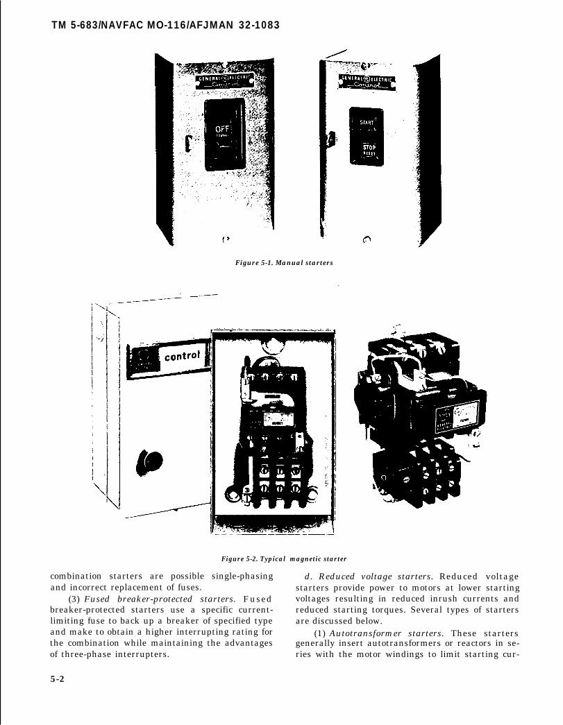
TM 5-683/NAVFAC MO-116/AFJMAN 32-1083
Figure 5-1. Manual starters
Figure 5-2. Typical magnetic starter
combination starters are possible single-phasingand incorrect replacement of fuses.
(3) Fused breaker-protected starters. Fusedbreaker-protected starters use a specific current-limiting fuse to back up a breaker of specified typeand make to obtain a higher interrupting rating forthe combination while maintaining the advantagesof three-phase interrupters.
d. Reduced voltage starters. Reduced voltagestarters provide power to motors at lower startingvoltages resulting in reduced inrush currents andreduced starting torques. Several types of startersare discussed below.
(1) Autotransformer starters. These startersgenerally insert autotransformers or reactors in se-ries with the motor windings to limit starting cur-
5-2

TM 5-683/NAVFAC MO-116/AFJMAN 32-1083/
RESPONSIBILITY
Maintenance Group(Operator/Electricians
User
Electrician
Electrician
Electrician
Table 15-3. Interior wiring and lighting system.
FREQUENCY
Each scheduledbuilding visit
AS Required
As required.
As required.
Monthly orAnnually
CHECK
Unauthorized or nonstandard attachments
Defective convenience outlets and switches.
Improper cords.
Proper fuse sizes in panels.
Overheating of panels.
Any condition likely to cause fire. Check battery-
type emergency lights and replacement lamps.Check for Iamps larger than standard prescribedfor outlet.
Replace burnt out lamps in hard-to-reach places.(To be accomplished by electrical shop if specialequipment such as ladder trucks are needed).
Panels for circuit idenificaton and accessibility.
Replace blown fuses.
Replace burnt out or defective incandescent lamps.
Replace burnt out fluorescent lamps if personnelhave been instructed in this function and if assignedto user. Promptly replace or report defectivelamps since a lamp approaching bum out flashes onand off, causing overduty on auxiliary equipment.
Make repairs and adjustments to systems whenmalfunctions are reported. Ensure that all workcomplies with the NEC
Check ground resistance for special weaponsfacilities at request of user.
Check for low voltages and/or low power factor.
Inspect station (substation switchgear or UPS) asfollows:
(1) Check electrolyte level and add distilled water ifneeded.(2) Check charging rate. Adjust charging rate asnecessary to maintain proper specific gravity.(3) Test for proper operation under simulatedpower interruption. Check maintenance freebatteries. Check voltage, check and cleanterrminal/connection.
REF.
5-4-4
9-7
9-6
5-4-1
5-4-4
9-6
9-6
14-5
13-2
2-8-3
15-3

TM 5-683/NAVFAC MO-116/AFJMAN 32-1083
I
6
4
Figure 5-4. Coordination of motor overload relay and current limiting fuse.
rents. At military installations, they typically rangein size from 5 to 200HP, and the voltage may varyfrom about 208V tQ 2300V. The autotransformerstarter provides greater starting torque per ampereof starting current drawn from the line than any
other reduced voltage motor starter. Two contractorsare usually u s e d f o r c o n n e c t i o n o f a nautotransformer starter. See figure 5-5. When thestart push button is pressed, start contactor “S”closes. This contactor serves to connect the auto-transformer to the line, and the motor to taps on theautotransformer. After a defined timely delay gov-erned by pneumatic timer TR, contactor “S” dropsout, and run contactor “R” closes, connecting themotor directly across the line. At this time, theautotransformer is disconnected from both the lineand the motor. It is important that contactor "S" isdropped out before contactor “R” closes since anyoverlapping of “R” and “S” in the closed position willresult in a short circuited autotransformer second-ary. This would cause high current to flow and sub-ject that winding to high thermal and magneticstresses. Standard autotransformers are equipped
with taps which allow them to be adjusted to oper-ate at different percents of line voltage. Small sizesare normally equipped with taps for 65 and 80 per-cent of line voltage, while larger sizes normallyhave 50, 65, and 80 percent taps.
(2) Resistance starters. This starter limits thestarting current by employing resistors in serieswith the motor windings. This provides a smoothstart and precise acceleration through a closed tran-sition to full voltage and avoids a sudden mechani-cal shock to the driven load. Power and controlcircuits of a resistance motor starter are given infigure 5-6. When the start button is pressed, startcontactor “S” connects the motor to the line with thestarting resistor in series and a pneumatic timer isalso picked up. After a time delay governed by timerTR, the TR/TC contacts close, Run contactor “R”closes, short-circuits the starting resistor, and con-nects the motor across the line.
(3) part-winding starters. These are used withsquirrel cage motors having two separate, parallelstator windings (fig 5-7). The motor is started onone winding through accelerating contactor “lM” at

TM 5-683/NAVFAC MO-116/AFJMAN 32-1083
L1 L2 L3
L1
MOTOR TR
L2
NOMENCLATURE
s Start ContactorR Run Contactor
TR Pneumatic TimerOL Overload Relay
TR/TO Contact Stays-Closed When TR Picks Up;It Opens After A Time Delay.
TR/TC Contact Stays Open When TR Picks Up;It Closes After A Time Delay.
Figure 5-5 Autotransformer starter.
about 2/3 of normal inrush current. After a period of ings for normal delta operation. This type is limitedacceleration governed by pneumatic timer-TR, theother winding is energized through run contactor‘2M”. This operation permits the use of contactorswhich are half as large as those required for thereduced-voltage starters, resulting in approxi-mately a 50 percent reduction in cost. However, themotor cannot carry its load until both windings areenergized.
(4) Wye-delta starters. A variation on the part-winding starter is the wye-delta type, which startsthe motor with the windings connected wye, andafter a period of acceleration, reconnects the wind-
to-wye-delta comectable motors but produces betterstarting torque at a lower inrush current and isused extensively with air-conditioning motors hav-ing a high inertia load and a long acceleration time.
(5) Solid-state starters. Solid-state starters (fig5-8) provide smooth, stepless acceleration of squir-rel cage motors from standstill to fill speed. It pro-vides extended starting times by supplying continu-ously varying voltage to the AC motor from zero tofull voltage. Controlled starting of a standard squir-rel cage motor is accomplished by supplying re-duced voltage to the motor terminals. This reduced

TM 5-683/NAVFAC MO-116/AFJMAN 32-1083
L1 L2 L 3
i
NOMENCLATURE
S START CONTACTOR
R RUN CONTACTOR
RA,RB,RC RESISTORS
TR PNEUMATIC TIMER
OL OVERLOAD RELAY
Figure 5-6. Resistance starter.
voltage produces reduced torque which means aslow, controlled acceleration. Typical applicationsthat require lower controlled starting torques arelarge pumps, compressors, and heavy material han-dling conveyors.
e. Two-speed starters. This circuit allows a motorto be started at low speed before running it at highspeed. Resistors might be utilized to provide areduced-voltage start or a separate, lower line volt-age may be available for low speed operation.
f. Starters and speed regulators for AC woundrotor and DC motors. This equipment is much morecomplex than the starting devices previously dis-
cussed. Specialized guidance is required to installand maintain this equipment. Consequently, themanufacturer’s diagrams and instructions shouldbe obtained and kept readily available.
g. Adjustable speed/frequency starters. AC ad- justable speed operation is obtained by convertingthe fixed frequency AC line power into an adjust-able voltage and frequency output which operatesthe AC motor at the desired speed. The input ACpower is converted to adjustable DC voltage by asolid-state converter module. The DC power is thenconverted by the inverter to produce AC outputpower at an adjustable frequency and voltage suit-able for operating either conventional AC inductionmotors or synchronous motors. Since the speed of anAC motor is a function of the applied frequency,accurate speed control is readily provided. Thesesystems are complex and may induce harmonics onthe electrical system which may, in turn, disrupt theoperation of nearby equipment. Maintenanceshould be performed by personnel experienced withsolid-state drives and controls.
h. Miscellaneous types. Other terms used to de-scribe motor controls include the following:
(1) Reversing starter. A motor that can be oper-ated in either a clockwise or counterclockwise direc-tion.
(2) Motor control center is the term given to agrouping of motor starters within a large enclosure(fig 5-9). The centers are used where several motorsare to be operated from a single location. The start-ers themselves may be magnetic across-the-linestarters or other types. A typical use would be in aboiler control room where the various fan, pump,conveyer, and other motors serving the boiler are allcontrolled from a central location.
5-3. Components and maintenance of motorcontrols.
Control equipment should be inspected and servicedsimultaneously with the motors. As a general rule,overhaul procedures for control equipment are lessinvolved than motor overhauling. Most repairs canbe made on-site. Motor starters represent one areain which simplicity of construction and wiring hasbeen emphasized by the manufacturers. Improve-ments have resulted in starters that are simple toinstall, maintain and operate. Connections arereadily accessible, some parts are of plug-in typeand may be easily replaced. Coils are often encap-sulated in epoxy compounds and are less likely toburn out. Practically all newer starters have provi-sions for adding several auxiliary contacts with verylittle effort. Spare parts for starters are usuallyavailable from local suppliers. Spare starters, as

TM 5-683/NAVFAC MO-116/AFJMAN 32-1083
LI L2 L3
—
II
sizes should be stocked in the regular shop supplychannels.
a. Enclosures. Enclosures do not normally re-quire maintenance when employed in a clean, dryand noncorrosive atmosphere. But in a marginalatmosphere, enclosures should be inspected andmaintained as recommended in paragraph 2-2. Thefrequency of these inspections should be dictated bythe corrosiveness of the atmosphere.
b. Electrical connections. Experience indicatesthat failures of electrical connections are the causeof many equipment burnouts and fires. Refer toparagraph 2–3 for recommended maintenance.
c. Molded case breakers. A wide variety of circuitbreakers are used in the military services. Thermal-magnetic molded case circuit breakers (fig 5-10) arepredominant in building panel boards and motorcontrol centers. They are available in bolt-in orplug-in types and in single-pole for two-wire
NOMENCLATURE
IM ACCELERATING CONTACTOR
2M RUN CONTACTORTR PNEUMATIC TIMER
OL OVERLOAD RELAY
three-wire ungrounded or three and four-wiregrounded circuits. Multiple units should be of thecommon trip type having a single operating handle.The need for maintenance on molded case breakerswill vary depending on operating conditions.Molded case breakers are relatively trouble-free de-vices requiring little maintenance. For the mostpart, maintenance will require only that conductorterminations are tight and free from corrosion, andthat the breaker is kept dry and free from excessiveaccumulations of dirt and dust. Because mostbreakers employ welded internal construction, theyrequire no internal servicing. An exception to this isthe trip unit, which is replaceable on breakers inlarger frame sizes. Periodic inspection should bemade to ensure that the trip unit hold-down boltsare tight. For breakers rated 100 amps and below,and where inspection indicates some type of repairis in order, "repair by replacement” is advisable.
5-7
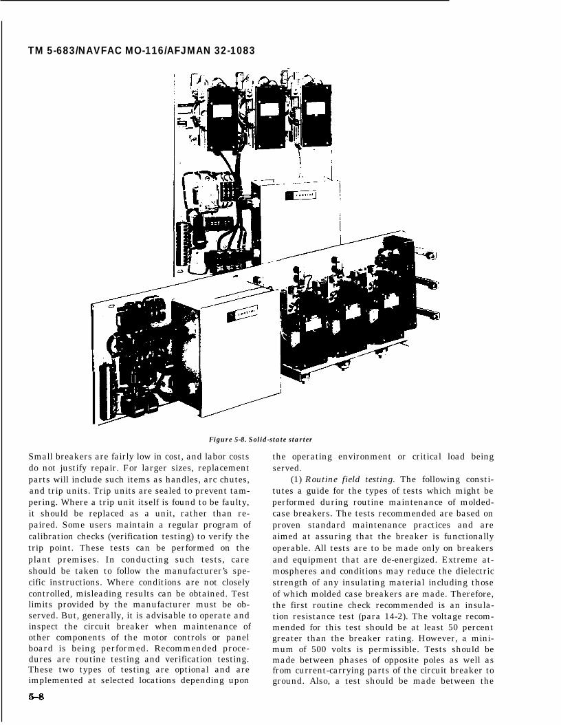
TM 5-683/NAVFAC MO-116/AFJMAN 32-1083
Figure 5-8. Solid-state starter
Small breakers are fairly low in cost, and labor costsdo not justify repair. For larger sizes, replacementparts will include such items as handles, arc chutes, and trip units. Trip units are sealed to prevent tam-pering. Where a trip unit itself is found to be faulty,it should be replaced as a unit, rather than re-paired. Some users maintain a regular program ofcalibration checks (verification testing) to verify thetrip point. These tests can be performed on theplant premises. In conducting such tests, careshould be taken to follow the manufacturer’s spe-cific instructions. Where conditions are not closelycontrolled, misleading results can be obtained. Testlimits provided by the manufacturer must be ob-served. But, generally, it is advisable to operate andinspect the circuit breaker when maintenance ofother components of the motor controls or panelboard is being performed. Recommended proce-dures are routine testing and verification testing.These two types of testing are optional and areimplemented at selected locations depending upon
the operating environment or critical load beingserved.
(1) Routine field testing. The following consti-tutes a guide for the types of tests which might beperformed during routine maintenance of molded-case breakers. The tests recommended are based onproven standard maintenance practices and areaimed at assuring that the breaker is functionallyoperable. All tests are to be made only on breakersand equipment that are de-energized. Extreme at-mospheres and conditions may reduce the dielectricstrength of any insulating material including thoseof which molded case breakers are made. Therefore,the first routine check recommended is an insula-tion resistance test (para 14-2). The voltage recom-mended for this test should be at least 50 percentgreater than the breaker rating. However, a mini-mum of 500 volts is permissible. Tests should bemade between phases of opposite poles as well asfrom current-carrying parts of the circuit breaker toground. Also, a test should be made between the

TM 5-683/NAVFAC MO-116/AFJMAN 32-1083
Figure 5-9. Typical motor control center.
line and load terminals with the breaker in the openposition. Resistance values below one megohm perkV of test voltage are considered unsafe and shouldbe investigated for possible contamination on thesurfaces of the molded case of the circuit breaker.Clean the molded case surface and retest. If lowmegohm readings persist, then replace the breaker.For individual breaker resistance readings, loadand line conductors should be disconnected from thebreaker under test. If not disconnected, the testmeasurements will also show resistance of the at-tached circuit. During routine testing, all circuitbreakers should be operated (while documenting)several times to ensure that the contacts are notfrozen and that the mechanical components func-tion without undue friction. This action will alsolessen the effect of any film that might have built upon the contacts. Check for cracked, warped or bro-ken case and replace if necessary. If there is evi-
dence of internal heating, or reason to suspect highcontact resistance or improper calibration, thebreakers should be replaced. It is recommendedthat molded-case breakers with removable covers bechecked for contact and latch cleanliness as well asconnection tightness. Lubrication should bechecked. If the operating mechanism appears dry,apply a drop of heavy oil or light grease at the wearpoints. Do not apply lubricant to the contacts or tothe trip unit. If the contacts are badly pitted, theyshould be cleaned with a fine file or sandpaper. Besure to avoid any accumulation of filings in thebreaker. Do not tamper with factory sealed break-ers.
(2) Verification field testing. Verification fieldtesting of molded case circuit breakers is intendedto check breaker operation versus manufacturer’spublished data. If molded case circuit breaker per-formance characteristics are to be tested in the
5-9
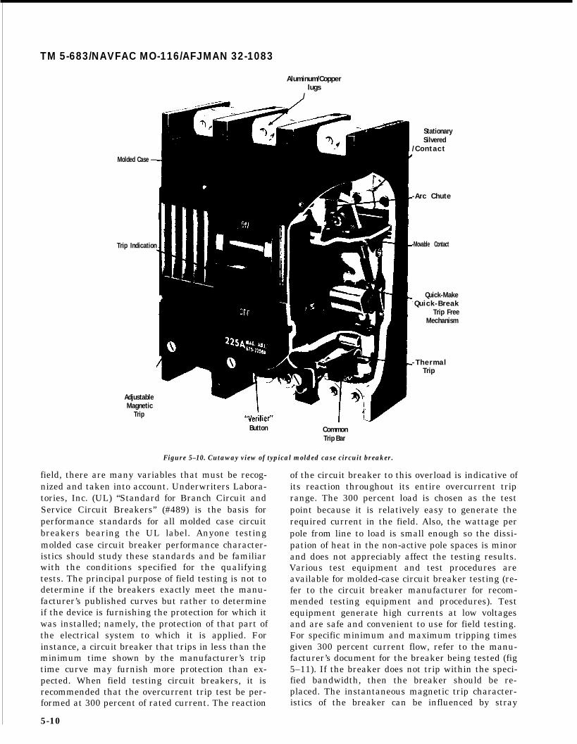
TM 5-683/NAVFAC MO-116/AFJMAN 32-1083
Aluminum/Copperlugs
/
Molded Case —
Trip Indication
AdjustableMagnetic
Trip
Button CommonTrip Bar
Figure 5–10. Cutaway view of typical molded case circuit breaker.
StationarySilvered
/ C o n t a c t
-Arc Chute
-Movable Contact
Quick-Make- Quick-Break
Trip FreeMechanism
- T h e r m a lTrip
field, there are many variables that must be recog-nized and taken into account. Underwriters Labora-tories, Inc. (UL) “Standard for Branch Circuit andService Circuit Breakers” (#489) is the basis forperformance standards for all molded case circuitbreakers bearing the UL label. Anyone testingmolded case circuit breaker performance character-istics should study these standards and be familiarwith the conditions specified for the qualifyingtests. The principal purpose of field testing is not todetermine if the breakers exactly meet the manu-facturer’s published curves but rather to determineif the device is furnishing the protection for which itwas installed; namely, the protection of that part ofthe electrical system to which it is applied. Forinstance, a circuit breaker that trips in less than theminimum time shown by the manufacturer’s triptime curve may furnish more protection than ex-pected. When field testing circuit breakers, it isrecommended that the overcurrent trip test be per-formed at 300 percent of rated current. The reaction
5-10
of the circuit breaker to this overload is indicative ofits reaction throughout its entire overcurrent triprange. The 300 percent load is chosen as the testpoint because it is relatively easy to generate therequired current in the field. Also, the wattage perpole from line to load is small enough so the dissi-pation of heat in the non-active pole spaces is minorand does not appreciably affect the testing results.Various test equipment and test procedures areavailable for molded-case circuit breaker testing (re-fer to the circuit breaker manufacturer for recom-mended testing equipment and procedures). Testequipment generate high currents at low voltagesand are safe and convenient to use for field testing.For specific minimum and maximum tripping timesgiven 300 percent current flow, refer to the manu-facturer’s document for the breaker being tested (fig5–11). If the breaker does not trip within the speci-fied bandwidth, then the breaker should be re-placed. The instantaneous magnetic trip character-istics of the breaker can be influenced by stray
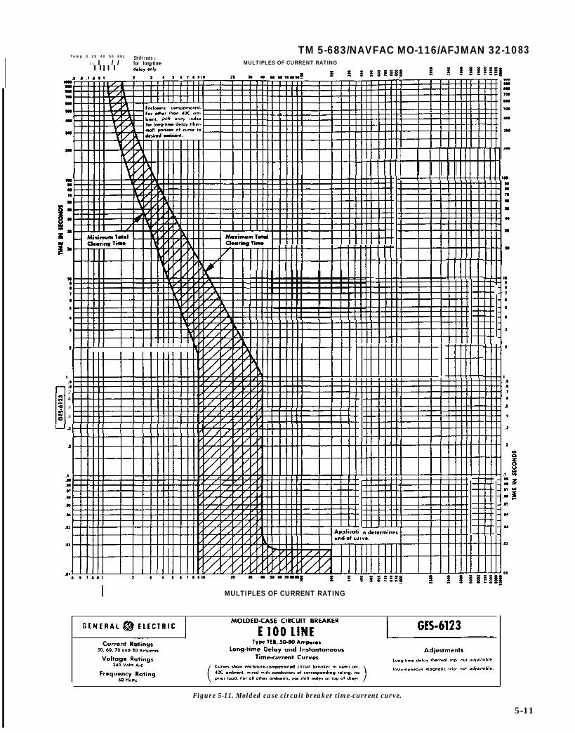
Temp 0 25 40 50 60cTM 5-683/NAVFAC MO-116/AFJMAN 32-10
Shift rods e.\ \ I / / for long-time MULTIPLES OF CURRENT RATING
83
1 I II [ 1 I I I I I I I I 1
I mi.7A
.s
.4
s
.4
I MULTIPLES OF CURRENT RATING
Figure 5-11. Molded case circuit breaker time-current curve.
5-11

TM 5-683/NAVFAC MO-116/AFJMAN 32-1083
magnetic fields. The test setup must be conductedin such a way that magnetic fields created by thetest equipment, steel enclosures, or the conductorsfrom the test equipment to the circuit breaker donot affect the test results.
d. Fuses. Fuses are among the oldest types ofovercurrent protectors. They are simple, rugged andinexpensive. They sense overcurrent conditionsthrough the development of heat in the conductingelements and accomplish their operation by de-struction of these elements. They offer both long-time and short-time short circuit protection and areused widely in the protection of small motors. Main-tenance of fuses should not be performed until allpower sources are disconnected (fig 5-12). At thattime, check the continuity of all fuses with an ohm-meter. A reading greater than zero ohms indicatesthat the fuse is blown and must be replaced. Inspectfuse terminals and fuse holder clips. Check that theportions of the fuse making contact in the clip areclean and bright; poor contact can cause overheat-ing which results in a discoloration of the contactsurfaces. If this occurs, then the oxidized surfacesshould be cleaned and polished. Silver-plated sur-faces should not be cleaned with an abrasive mate-rial. Wiping contacts with a noncorrosive cleaningagent is recommended. Tighten all fuse holder con-nections. Fuse clips should exert sufficient pressureto maintain good contact, which is essential forproper fuse performance. Clips which make poorcontact should be replaced. Clip clamps are recom-. .
when unsatisfactory clips
PREVENTIVEMAINTENANCE
IS FUSE TIGHT IN CIRCUIT?
cannot be re-
ARE FUSE AND HOLDERS CLEAN AND DRY?
OVERHEATING?
ARE RIGHT TYPE AND SIZE IN CIRCUIT?
placed. Replace fuses showing signs of deteriorationsuch as discolored or damaged casings or pittedcontact surfaces. There are many types of fuses (fig5-13) with various characteristics, some of whichare physically interchangeable. Make certain thatfuses are of the proper type and rating. Never re-place one type of fuse arbitrarily with another typefuse of the same physical size simply because it fitsthe fuse holder. A continuity check should also beperformed on replacement fuses to ensure their in-tegrity. Fuses should have correct current and volt-age ratings, proper time-delay or current-limitingcharacteristics and an adequate interrupting ratingto protect the circuit and its components Currentratings of fuses protecting transformers or motorsshould be selected at or near the fill load current.Voltage ratings of fuses should equal or exceed theircircuit voltage. Interrupting ratings of fuses shouldequal or exceed the available fault current at thefuse holder. UL listed fuses without marked inter-rupting ratings are satisfactory only on circuitswhere fault currents do not exceed 10,000 amperes.Non-current-limiting fuses should not be used toreplace current-limiting fuses since fuse holders forUL listed current-limiting fuses are designed to re-ject fuses which are not current limiting. Fuse hold-ers and rejection clips should never be altered orforced to accept fuses which do not readily fit. Anadequate supply of spare fuses, especially thosewhich are uncommon, will minimize improper re-placement.
CORRECTIVEMAINTENANCE
● TEST FOR CONTINUITY, SINGLE PHASING
● WHAT OPENED FUSE?
-- SHORT?
-- OVERLOAD?
-- HIGH TEMPERATURE DERATING?
● REPLACE WITH RIGHT TYPE AND SIZE.
Figure 5-12. Fuse maintenance practices.

TM 5-683/NAVFAC MO-116/AFJMAN 32-1083
r
CARTRIDGE FUSESNON CURRENT LIMITING 0-600 v. CURRENT LIMITING
1
II
Ir
“MISCELLANEOUS" CLASS G 300 VOLTS
MIDGET DIMENSION, ETC.TESTED AND UL LISTED
SPECIAL DIMENSIONS “600 VOLTS OR LESS”
1
1 CLASS J 0-600 AMPS.100,000 OR 2OO,OOO/AC
CLASS L 601-6000 AMPS100,000 OR 200,00/AC
iRENEWABLELINK FUSES I
CLASS K-1 : CLASS K-9:HIGH DEGREE OF FAIR DEGREE OF
CURRENT LIMITATION. CURRENT LIMITATION.
Figure 5-13. Underwriters’ Laboratories cartridge fuse classification.
e. Thermal overloads. Thermal overload relayscontained in starters provide more precise motorprotection against overloads and momentary surgesthan fuses or circuit breakers. However, they do notprovide short circuit protection. Relays themselvesrequire little maintenance other than occasionaltesting to ensure that they are operational. Thermaloverloads should be checked and resized wheneverthe motor is replaced to adequately protect the mo-tor. The relays are controlled by heater elements (fig5-14) which are in series with the motor current.The size of the heater must match the motor beingprotected. Be especially careful if the motor hasbeen oversized to compensate for lower load currentwith lower rated heaters to cause tripping on loss ofone phase (single phasing). It often happens thatthe wrong size heaters are installed. If the heater istoo small, the overload relays act to take the motoroff line unnecessarily. If too large, the motor willoperate without proper protection and could bedamaged from overload. If the relays frequently op-erate to take the motor off line, the heaters shouldbe checked first. If the heaters are properly sized(about 120 percent of motor full load current) andthere are no unusual temperature conditions, thencheck the motor current. If the motor current ishigher than the nameplate rating by a margin suf-ficient to exceed the heater rating, then the relay isoperating properly, and the motor is either over-loaded or in fault, therefore, check the motor. Do notput in larger heaters. If however, the motor stopsfrequently even though the heaters are correctly
sized and the line current and ambient temperatureare normal, then check the relays. The relaysshould be tested and replaced if required. Unfortu-nately, the overload relays that serve as safetyvalves to protect the motors from burnouts due tofaults and overloads, sometimes fail to respondproperly. For example, aging and inactivity followedby metal fatigue in some relay types may result in afailure to operate under conditions of overload. Pe-riodic testing of the relays under load conditions,checking the tightness of all overload connectionsand inspecting for contact overheating and cleanli-ness forms an important part of a good motor con-trol maintenance program. Suitable test instru-ments are available that provide a dummy load tothe relay and measure the time interval required toopen the contacts. Their use is highly recom-mended, especially on relays for motors that servecritical loads; e.g., motors driving air conditionerswhich are used for communication or data process-ing equipment, or motors on production lines. Formost applications, testing of motor overload relaysshould be conducted every 2 years. Regular testingof thermal overload motor relays is a recommendedprocedure for all installations. Overload relays em-ploy a thermal element designed to interpret anoverheating condition in the motor winding by con-verting the current in the motor leads to heat in theoverload relay element. As the heat in the elementapproaches a predetemnined value, the control cir-cuit to the magnetic contactor holding coil is inter-rupted and the motor branch circuit is opened. The
5-13
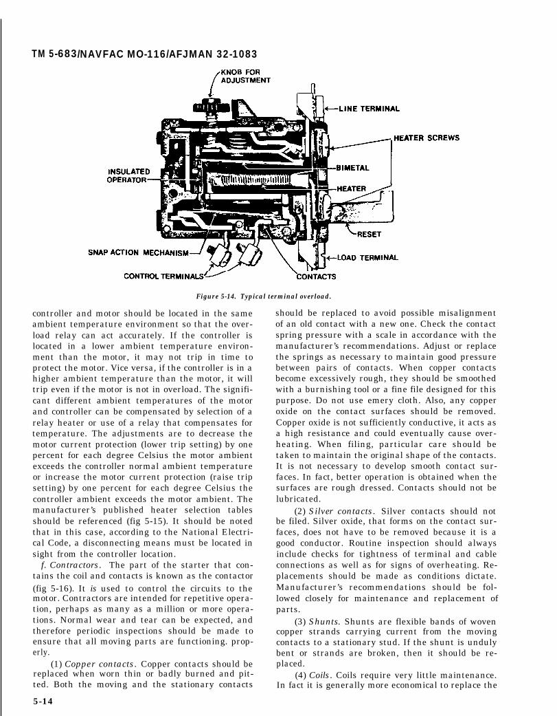
TM 5-683/NAVFAC MO-116/AFJMAN 32-1083
Figure 5-14. Typical terminal overload.
controller and motor should be located in the sameambient temperature environment so that the over-load relay can act accurately. If the controller islocated in a lower ambient temperature environ-ment than the motor, it may not trip in time toprotect the motor. Vice versa, if the controller is in ahigher ambient temperature than the motor, it willtrip even if the motor is not in overload. The signifi-cant different ambient temperatures of the motorand controller can be compensated by selection of arelay heater or use of a relay that compensates fortemperature. The adjustments are to decrease themotor current protection (lower trip setting) by onepercent for each degree Celsius the motor ambientexceeds the controller normal ambient temperatureor increase the motor current protection (raise tripsetting) by one percent for each degree Celsius thecontroller ambient exceeds the motor ambient. Themanufacturer’s published heater selection tablesshould be referenced (fig 5-15). It should be notedthat in this case, according to the National Electri-cal Code, a disconnecting means must be located insight from the controller location.
f. Contractors. The part of the starter that con-tains the coil and contacts is known as the contactor(fig 5-16). It is used to control the circuits to themotor. Contractors are intended for repetitive opera-tion, perhaps as many as a million or more opera-tions. Normal wear and tear can be expected, andtherefore periodic inspections should be made toensure that all moving parts are functioning. prop-erly.
(1) Copper contacts. Copper contacts should bereplaced when worn thin or badly burned and pit-ted. Both the moving and the stationary contacts
5-14
should be replaced to avoid possible misalignmentof an old contact with a new one. Check the contactspring pressure with a scale in accordance with themanufacturer’s recommendations. Adjust or replacethe springs as necessary to maintain good pressurebetween pairs of contacts. When copper contactsbecome excessively rough, they should be smoothedwith a burnishing tool or a fine file designed for thispurpose. Do not use emery cloth. Also, any copperoxide on the contact surfaces should be removed.Copper oxide is not sufficiently conductive, it acts asa high resistance and could eventually cause over-heating. When filing, particular care should betaken to maintain the original shape of the contacts.It is not necessary to develop smooth contact sur-faces. In fact, better operation is obtained when thesurfaces are rough dressed. Contacts should not belubricated.
(2) Silver contacts. Silver contacts should notbe filed. Silver oxide, that forms on the contact sur-faces, does not have to be removed because it is agood conductor. Routine inspection should alwaysinclude checks for tightness of terminal and cableconnections as well as for signs of overheating. Re-placements should be made as conditions dictate.Manufacturer’s recommendations should be fol-lowed closely for maintenance and replacement ofparts.
(3) Shunts. Shunts are flexible bands of wovencopper strands carrying current from the movingcontacts to a stationary stud. If the shunt is undulybent or strands are broken, then it should be re-placed.
(4) Coils. Coils require very little maintenance.In fact it is generally more economical to replace the

TM 5-683/NAVFAC MO-116/AFJMAN 32-1083
Figure 5-15. Typical heater selection table for thermal overload device.
coil than it is to attempt repairs. Coils will operate they should be dried out by spraying a contactefficiently at 85 to 110 percent of rated voltage.Higher voltages shorten life and lower voltages mayresult in failure to close the contacts completely.This could result in welded contacts. Coil burnoutalso could occur if the contactor fails to close prop-erly either from being blocked or by low voltage. Ineither case, the current flowing through the coil islarger than rated because of the larger air gap inthe magnetic circuit. Maintenance consists of clean-ing out accumulated dust and grease, if any, andinspecting the coil to see that it is of proper ratingand operates properly. When handling coils, do notpick the coil up by its leads. If coils become wet,
cleaning chemical on the coil or by heating the coilin an oven at 110 degrees C to 125 degrees C. If it isnecessary to varnish coils, use only an approvedinsulating treatment applied while the coils are stillwarm from baking. These instructions on dryingand varnishing coils do not apply to the newer en-capsulated types.
5-4. Preventive maintenance and trouble-shooting guide.
Table 5-1 outlines typical preventive maintenancefor a motor control. Table 5-2 lists troubleshootingand corrective maintenance practices.
5-15

TM 5-683/NAVFAC MO-116/AFJMAN 32-1083
.
Figure 5-16. A NEMA size 6 magnetic contactor (Courtesy of Siemens-Allis).
5-16

TM 5-683/NAVFAC MO-116/AFJMAN 32-1083
Table 5-1. Motor control preventive maintenance guide.
WHAT TO INSPECT
1. Exterior and Surroundings
2. Interior of Enclosure,Nuts and Bolts
3. Contactors, Relays,Solenoids
a. General
b. Contact Tips
c. Springs
d. Flexible leads
e. Arc Chutes
f. Bearings
g. Coils
h. Magnets
WHAT TO INSPECT FOR
Dust, grease, oil; hightemperature; rust andcorrosion; mechanical damage;condition of gaskets, if any.
Same as for No. 1 plus excessvibration which may haveloosened nuts, bolts or othermechanical connections.
Check control circuit voltage;inspect for excess heating ofparts evidenced bydiscoloration of metal,charred insulation or odor;freedom of moving parts; dust,grease, and corrosion; looseconnections.
Check for excessive pitting,roughness, copper oxide; donot file silver contacts.
Check contact pressure; ispressure same on all tips.
Look for frayed or brokenstrands; be sure lead isflexible - not brittle.
Check for breaks or burning.
Check for freedom of movement;do not oil.
Look for overheating, charredinsulation or mechanicalinjury.
Clean faces; check shadingcoil; inspect formisalignment, bonding.
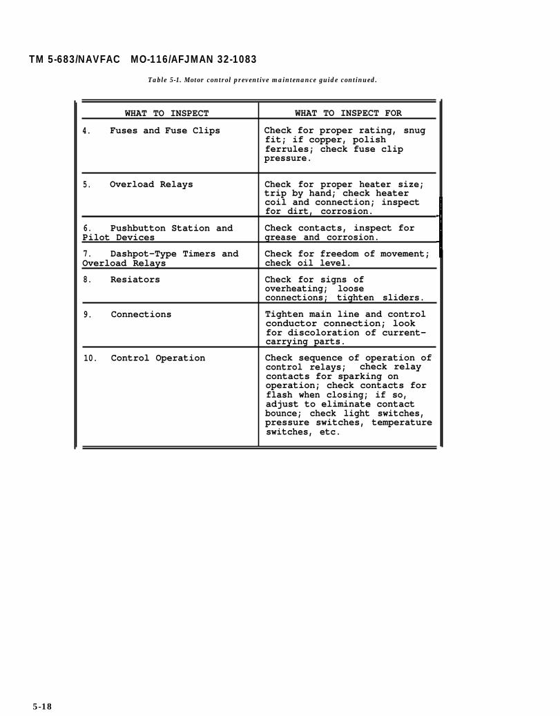
TM 5-683/NAVFAC MO-116/AFJMAN 32-1083
Table 5-1. Motor control preventive maintenance guide continued.
WHAT TO INSPECT WHAT TO INSPECT FOR
4. Fuses and Fuse Clips Check for proper rating, snugfit; if copper, polishferrules; check fuse clippressure.
5. Overload Relays Check for proper heater size;trip by hand; check heatercoil and connection; inspectfor dirt, corrosion.
6. Pushbutton Station and Check contacts, inspect forPilot Devices grease and corrosion.
7. Dashpot-Type Timers and Check for freedom of movement;Overload Relays check oil level.
8. Resiators Check for signs ofoverheating; looseconnections; tighten sliders.
9. Connections Tighten main line and controlconductor connection; lookfor discoloration of current-carrying parts.
10. Control Operation Check sequence of operation ofcontrol relays; check relaycontacts for sparking onoperation; check contacts forflash when closing; if so,adjust to eliminate contactbounce; check light switches,pressure switches, temperatureswitches, etc.
5-18

TM 5-683/NAVFAC MO-116/AFJMAN 32-1083
Table 5-2. Motor control troubleshooting chart.
CAUSE
1. Contactor or Relay Doesnot Close
No supply voltage.
Low voltage.
Coil open or shorted.
Wrong coil.
Mechanical
Pushbuttonmaking.
obstruction.
contacts not
Interlock or relay contactnot making.
Loose connection.
Overload relay contact open.
2. Contactor or Relay Does NotOpen
Pushbutton not connectedcorrectly.
Shim in magnetic circuit (DConly) worn, allowingresidual magnetism to holdarmature closed.
Interlock or relay contactnot opening circuit.
“Sneak” circuit.
Gummy substance on polefaces.
Worn or rusted parts causingburning
Contacts weld shut.
REMEDY
Check fuses and disconnectswitches.
Check power supplY. Wire may beto small.
Replace.
Check coil number.
With power off, check for freemovement of contact and armatureassembly.
Clean or replace if badly worn.
Adjust or replace if badly worn.
Turn power off first, then checkthe circuit visually with aflashlight.
Reset
Check connections with wiringdiagram.
Replace.
Adjust contact travel.
Check control wiring forinsulation failure.
Clean with solvent.
Replace parts.
See Item 3.
5-19

TM 5-683/NAVFAC MO-116/AFJMAN 32-1083
Table 5-2. Motor control trouble-shooting chart-continued.
CAUSE
3. Contacts weld shut orfreeze
Insufficient contact springpressure causing contacts toburn and draw arc on closing.
Very rough contact surfacecausing current to be carriedby too small an area.
Abnormal inrush of current.
Rapid jogging.
Low voltage preventing magnetfrom sealing.
Foreign matter preventingcontacts from closing.
Short circuit.
4. Contact Chatter
Broken pole shader.
Poor contact in controlcircuit.
Low voltage.
5. Arc Lingers AcrossContacts
If blowout is series, it maybe shorted.
If blowout is shunt, it may beopen circuited.
Arc box might be left off ornot in correct place.
If no blowout used, notetravel of contacts.
REMEDY
Adjust, increasing pressure.Replace if necessary.
Smooth surface or replace ifbadly worn.
Use larger contactor or checkfor grounds, shorts orexcessive motor load current.
Install larger device ratedfor jogging service or cautionoperator.
Correct voltage condition.Check momentary voltage dipduring starting.
Clean contacts with approvedsolvent.
Remove short circuit fault andcheck to be sure fuse orbreaker size is correct.
Replace.
Improve contact or use holdingcircuit interlock (3-wirecontrol).
Correct voltage condition.Check momentary voltage dipduring starting.
Check wiring diagram to seekind of blowout.
Check wiring diagram throughblowout.
See that arc box is oncontactor as it should be.
Increasing travel of contactsincreases rupturing capacity.
5-20
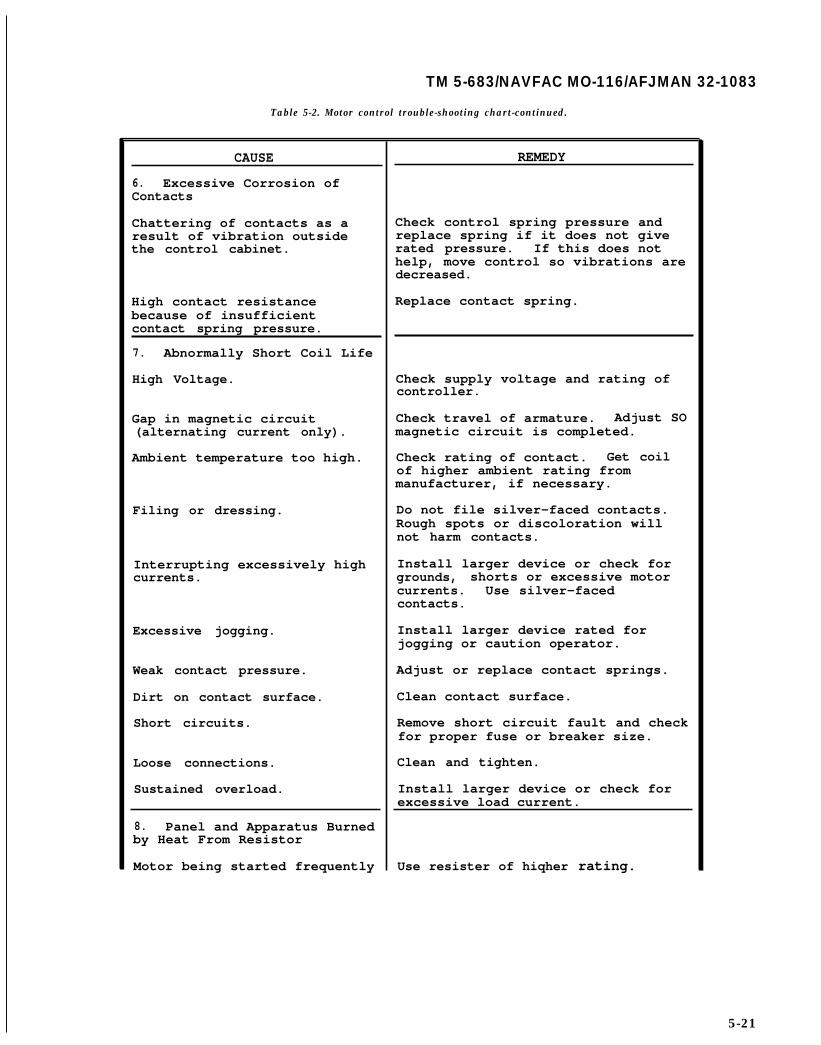
TM 5-683/NAVFAC MO-116/AFJMAN 32-1083
Table 5-2. Motor control trouble-shooting chart-continued.
CAUSE
6. Excessive Corrosion ofContacts
Chattering of contacts as aresult of vibration outsidethe control cabinet.
High contact resistancebecause of insufficientcontact spring pressure.
7. Abnormally Short Coil Life
High Voltage.
Gap in magnetic circuit(alternating current only).
Ambient temperature too high.
Filing or dressing.
Interrupting excessively highcurrents.
Excessive jogging.
Weak contact pressure.
Dirt on contact surface.
Short circuits.
Loose connections.
Sustained overload.
8. Panel and Apparatus Burnedby Heat From Resistor
Motor being started frequently
REMEDY
Check control spring pressure andreplace spring if it does not giverated pressure. If this does nothelp, move control so vibrations aredecreased.
Replace contact spring.
Check supply voltage and rating ofcontroller.
Check travel of armature. Adjust SOmagnetic circuit is completed.
Check rating of contact. Get coilof higher ambient rating frommanufacturer, if necessary.
Do not file silver-faced contacts.Rough spots or discoloration willnot harm contacts.
Install larger device or check forgrounds, shorts or excessive motorcurrents. Use silver-facedcontacts.
Install larger device rated forjogging or caution operator.
Adjust or replace contact springs.
Clean contact surface.
Remove short circuit fault and checkfor proper fuse or breaker size.
Clean and tighten.
Install larger device or check forexcessive load current.
Use resister of hiqher rating.
5-21

TM 5-683/NAVFAC MO-116/AFJMAN 32-1083
Table 5-2. Motor control trouble-shooting chart-continued.
CAUSE REMEDY
9. Coil Overheating
Overvoltage or high ambient Check application and circuit.temperature.
Incorrect coil. Check rating and replace withproper coil if incorrect.
Shorted turns caused by Replace coil.mechanical damage orcorrosion.
Correct pole faces.Undervoltage, failure ofmagnet to seal in.
Clean pole faces.Dirt or rust on pole facesincreasing air gap.
10. Overload Relays Tripping
Sustained overload. Check for grounds, shorts orexcessive motor currents.
Loose connection on load Clean and tighten.wires.
Relay should be replaced withIncorrect heater. correct size heater unit.
11. Overload Relay Fails toTrip
Clean or replace.Mechanical binding, dirt,corrosion, etc.
Check ratings. Apply properWrong heater or heaters heaters.omitted and jumper wires used.
Adjust relay ratingMotor and relay in different accordingly or maketemperatures. temperature the same for both.
12. Noisy Magnet (Humming)
Broken shading coil. Replace shading coil.
Magnet faces not mating. Replace magnet assembly orrealign.
Dirt or rust on magnet faces. Clean and realign.
Low voltage. Check system voltage andvoltage dips during starting.
5-22
TM 5-683/NAVFAC MO-116/AFJMAN 32-1083
CHAPTER 6
POWER CABLES
6-1. Components.
Power cables are generally made up of threecomponents: conductor, insulation and protectivecovering. The single most important component of acable is its insulation. The best way to ensure con-tinued reliability of a power cable is through visualinspection and electrical testing of its insulation.The guidance provided here applies only to cablesrated 600V AC or less and, to the occasional appli-cations found in DC motor drives operating at 500,600, or 700v DC or less.
6-2. Visual inspection.
A visual inspection of a power cable can be madewith power on. However, if the visual inspection isto include touching, handling or moving cables inmanholes or at terminations, then all circuits in thegroup to be inspected should be de-energized beforethe work is started.
a. Manhole installations. Manholes are not usu-ally located inside buildings. Terminations andsplices of non-lead cables should be squeezed insearch of soft spots, and inspected for tracking orsigns of corona. The ground braid should be in-spected for corrosion and tight connections. Inspectthe bottom surface of the cable for wear or scrapingdue to movement at the point of entrance into themanhole and also where it rests on the cable sup-ports. Inspect the manhole for spalling concrete ordeterioration above ground. If the manhole isequipped with drains, these may require cleaningor, in some instances, it may be necessary to pumpwater from the manhole prior to entrance. Do notenter a manhole unless a test for dangerous gas hasbeen made and adequate ventilation gives positiveassurance that entry is safe. High voltage cablesmay be present fireproofed with asbestos containingmaterials which pose additional health hazards.Potheads should be inspected for oil or compoundleaks and cracked or shipped porcelains. Theprocelain surfaces should be cleaned and if the con-nections are exposed, their tightness should bechecked. Since inspection intervals are normallyone year or more, comprehensive records are animportant part of the maintenance inspection. Theyshould be arranged so as to facilitate comparisonfrom one year to the next. Cables in manholes,ducts or below grade installations should be in-spected for the following:
(1) Sharp bends in the cables.
(2) Physical damage.(3) Excessive tension.(4) Cables laying under water.(5) Cable movement or dangling.(6) Insulation swelling.(7) Soft spots.(8) Cracked protective coverings.(9) Damaged fireproofing.(10) Poor ground connections or high imped-
ance to ground.(11) Deterioration of metallic sheath bond.(12) Corrosion of cable supports or trays.
b. Raceway and cable tray installations. Since theraceway or cable tray is the primary mechanicalsupport for the cable, it should be inspected forsigns of deterioration or mechanical damage. Thecable jacket should also be checked for abrasions ormechanical damage.
6-3. Cable insulation testing.
The electrical test most often conducted to deter-mine the quality of low voltage cable insulation isthe insulation resistance test (para 14-2). It is per-formed as a routine maintenance test for cablesalready in service or as an acceptance test for newcables. DC overpotential testing is another way oftesting cable insulation. This test is performed pri-marily on medium and high voltage cables to testtheir dielectric strength and is not recommended forroutine maintenance testing of low voltage cables.The insulation resistance test for low voltage cablesis usually performed using a megohmmeter (para13-4). It is a simple, quick, convenient and nonde-structive test that can indicate the contamination ofinsulation by moisture, dirt or carbonization. Beforetesting any cable, the circuit must be de-energized.Once that is done, it is usually best to disconnectthe cable at both ends in order to test only the cable,and to avoid error due to leakage across or throughswitchboards or panelboards. For an acceptancetest, cable less than or equal to 300 V maybe testedat 500 V and cable greater than 300 V but less than600 V maybe tested at 1,000 V. For a routine main-tenance test, test voltage should be restricted to 60percent of the factory test voltage. The test voltageshould be applied from phase to ground on eachconductor with the shielding tapes and metallicjackets also connected to ground (fig 6-l). While nogeneral standard exists for minimum acceptable in-sulation resistance values for cables in service, a“rule-of-thumb” of one megohm of resistance (mini-
6-1
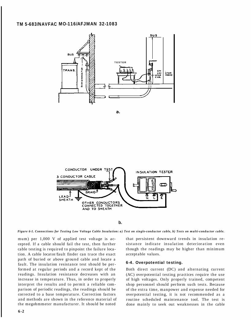
TM 5-683/NAVFAC MO-116/AFJMAN 32-1083
TESTER
b.
Figure 6-1. Connections for Testing Low Voltage Cable Insulation: a) Test on single-conductor cable, b) Tests on multi-conductor cable.
mum) per 1,000 V of applied test voltage is ac-cepted. If a cable should fail the test, then furthercable testing is required to pinpoint the failure loca-tion. A cable locator/fault finder can trace the exactpath of buried or above ground cable and locate afault. The insulation resistance test should be per-formed at regular periods and a record kept of thereadings. Insulation resistance decreases with anincrease in temperature. Thus, in order to properlyinterpret the results and to permit a reliable com-parison of periodic readings, the readings should becorrected to a base temperature. Correction factorsand methods are shown in the reference material ofthe megohmmeter manufacturer. It should be noted
6-2
that persistent downward trends in insulation re-sistance indicate insulation deterioration eventhough the readings may be higher than minimumacceptable values.
6-4. Overpotential testing.
Both direct current (DC) and alternating current(AC) overpotential testing practices require the useof high voltages. Only properly trained, competentshop personnel should perform such tests. Becauseof the extra time, manpower and expense needed foroverpotential testing, it is not recommended as aroutine scheduled maintenance tool. The test isdone mainly to seek out weaknesses in the cable

TM 5-683/NAVFAC MO-116/AFJMAN
c.
d.
32-1083
e.
Figure 6-1. (Continued) c) Use of the “guard” terminal to eliminate measure of surface leakage across exposed insulation atone end of cable, d) Use of a “spare” conductor to guard both ends of a multi-conductor cable, e) Use of "guard” to
eliminate all surface leakages except conductor under test.
6-3

TM 5-683/NAVFAC M-116/AFJMAN 32-1083
I INSULATIONTESTER I
f.
g.
h.
Figure 6-1. (Continued) f) Connection for testing total resistance between one conductor and all others plus ground, g) Testing oneconductor leakage to ground only, h) Testing one conductor to others in the bundle-leakage to ground eliminated by guard.

TM 5-683/NAVFAC M-116/AFJMAN 32-1083
insulation system that otherwise may not show upduring insulation resistance testing. Overpotentialtesting may be desirable as an overall quality accep-tance test after installation, modifications, or ex-pansion of a feeder cable system; as an additionalcheck of critical, emergency power feeder cables; asan additional quality check that is known to haveconducted high current due to a short circuit faultin the connected equipment; or, as a quality checkafter cable splices have been made. Overpotentialtesting is not recommended as a periodic, routinemaintenance test under three conditions. First, ifthe cable cannot be completely disconnected or iso-lated from the connected load(s) or auxiliary devicessuch as surge capacitors, lightning arresters, fuses,cutouts, and switchgear bus, second, if unacceptablereadings have already been obtained from generalinsulation resistance testing, and third, if the cablesare known to be laying under water.
a. Direct current (DC) tests. There are two meth-ods used for DC overpotential testing. In the firstmethod, the voltage is raised gradually to the speci-fied level. The rate of increase should be adjusted tomaintain a steady charging and leakage current.The current for a DC testis measured in microam-pere. Sixty to ninety seconds has been found to bean acceptable average time to reach the final testvoltage level. When this level has been reached,leakage current readings are taken and recorded atO, 1, 2, 3, 4, and 5 minutes. After the last reading,the voltage is slowly lowered and the cable is al-lowed to fully discharge. The second method iscalled the step method. Using this procedure, thetest voltage is raised in steps at given intervals. Theleakage current is measured and recorded at each
new voltage level as well as the O, 1, 2, 3, 4 and 5minute intervals after the final test voltage hasbeen reached. The step method is intended to catchan undesirable trend in the leakage current beforethe cable actually fails. The test can be stoppedbefore the final voltage is reached. An engineeringjudgment will be required to determine if the cableshould be left in service or if remedial measuresshould be taken. In both test methods, good inter-pretation of the leakage current magnitudes andthe trends is necessary. Temperature, humidity, andinsulation surface conditions affect the readings.Table 6-1 should be used as a guide in determiningthe specified test voltages.
b. Alternating current (AC) tests. AC overpo-tential testing is severe and possibly destructive tothe cable under test. In the AC test, the voltage isquickly raised from zero to the specified level. Thetest is usually held for one minute. The current ismeasured in milliamperes; however, its value is notimportant. The reading of current is provided sothat the person running the test can determine ifthe particular test set has sufficient capacity for thetask at hand. If the cable withstands the oneminute application, the test has been passed. Fail-ure results in short circuit and a ruined portion ofthe cable. The test set is designed to trip off imme-diately upon detection of the fault current. Table6-1 gives the recommended test levels.
6-5. Cable trouble-shooting.
Table 6-2 provides information regarding the mostcommon cable failure: overheating. Probable causesof overheating cables are listed along with recom-mended practices to remedy the problems.

INSULATION THICKNESS A-C TEST VOLTAGE D-C TEST VOLTAGERated CircuitVoltage, Phase 100 Percent 133 Percent 100 Percent 233 Percent 100 Percentto Phase, Volts Conductor
233 PercentInsulatation Level Insulation Level
Size AWG orInsulation Level Insulation Level Insulation Level Insulation Level
MCM* mils mm mils mm kV kV kV kV
0-600 14-9 30 0.76 30 0.76 4.0 4.0 12.0 12.08-2 45 1.14 45 1.14 5.5 5.5 16.5 16.5
1-4/0 55 1.40 55 1.40 7.0 7.0 21.0 21.0225-500 65 1.65 65 1.65 8.0 8.0 24.0 24.0
500-1000 80 2.03 80 2.03 10.0 10.0 30.0 30.0
* MCM-Thousands of circular mils.
100 percent level - Cables in this category may be applied where 133 Percent Level - This insulation level corresponds to that formerly designated forthe system is provided with relay protection such that ground faults ungrounded systems. Cables in this category may be applied in situations where the clearingwill be cleared as rapidly as possible, but in any cause within 1 time requirements of the 100 percent level category cannot be met, and yet there is adequateminute. While these cables are applicable to the great majority of assurance that the faulted section will be de-energized in a time not exceeding 1 hour. Alsocable installations which are on grounded systems, they may be used they may be used when additional insulation strength over the 100 percent level category isalso on other systems for which the application of cables is desirable.acceptable provided the above clearing requirements are met incompletely de-energizing the faulted section.
CABLE RATED O-600VOZONE-RESISTANT EHYLENE-PROPYLENE RUBBERINSULATION (IPCEA S-68-51G, NEMA WC 8-1971).

TM 5-683/NAVFAC M-116/AFJMAN 32-1083
Instal lat ion
Cables in racks
Cables in floorchannels.
Cables in tunnels
Table 6-2. Cable maintenance--overheating problems.
Cause of overheating
Heat from lower cablesin vert ical racksrises and heats uppercables.
Cables spacedhor izontal ly af fectedby mutual heating.
Cables closely spacedor in a location whereheat is confined, s u c has near ceil ings, etc.
External sources ofheat.
Mutual heating ofcables that have beenpiled aimlessly inovercrowded floorchannels.
Restr ict ion of a ircirculat ion by sol idcovers on channels.
Overloading
Mutual heatingcables spaced
oftoo
closely on rack.
External sources ofheat.
Remedy
Provide baffles to deflectrising warm air.
Increase space between cables.(For beat cooling, minimuncenter-to-center distancebetween cables should be twicethe cable diameter).
If constricted portion of cablerun is short, fans can be setup to provide cooling.
Re-route cable or remove heatsource.
Shield cables from heat orvent i la tor wi th fan.
Rack cables systematically andmaintain spacing necessary tominimize mutual heating.
Where practical, replace solidcovers with perforated coversto increase air circulation.
Re-route part of load fromoverloaded cables to cablescarrying lighter loads.
Space cables on racks tominimize mutual heating. Placecables near the floor.
Force air circulation throughtunnel.
Insulate adequately from theexternal heat source.
6-7

TM 5-683/NAVFAC MO-116/AFJMAN 32-1083
Table 6-2. Cable maintenance--overheating problems--continued.
Installation
Cables inundergroundducts
Cables buriedin earth.
Aerial Cables
Cable Risers
Cause ofoverheating
Overloading,addition ofloaded cables toduct bank withoutreducing therating of cablesalready in bank
Overloading
Overloads.
Cable in hot sun.
Cable chosen forundergroundoperation insteadof in a conduitin air.
Heating airrising andtrapped at top ofconduit.
Exposure to sun.
Remedy
Transfer load fromoverloaded cables tocables carrying lighterloads. Place powercables in outside ductswith most heavily loadedcables at the corners ofbank.
Install ventilatingcovers on congestedmanholes.
(A fan to force air outthrough a ventilatingcover may help).
Wetting dry soil improvesits conductivity, and mayslightly improve cablecapacity. Only realremedy is transferringportion of load toanother circuit.
Reduce load.
If practical, shade fromsun.
Capacity can be increased15 percent by separatingcables installed in onering.
Provide fans to coolrisers during overloadperiods.
Provide ventilatingbushing at top ofconduit.
Shade risers, ifpossible.
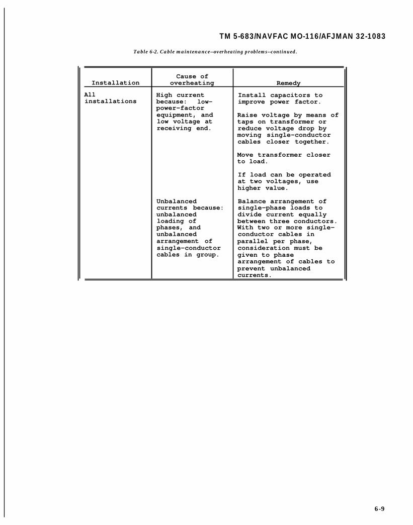
TM 5-683/NAVFAC MO-116/AFJMAN 32-1083
Table 6-2. Cable maintenance--overheating problems--continued.
Cause ofInstallation overheating Remedy
All High current Install capacitors toinstallations because: low- improve power factor.
power-factorequipment, and Raise voltage by means oflow voltage at taps on transformer orreceiving end. reduce voltage drop by
moving single-conductorcables closer together.
Move transformer closerto load.
If load can be operatedat two voltages, usehigher value.
Unbalanced Balance arrangement ofcurrents because: single-phase loads tounbalanced divide current equallyloading of between three conductors.phases, and With two or more single-unbalanced conductor cables inarrangement of parallel per phase,single-conductor consideration must becables in group. given to phase
arrangement of cables toprevent unbalancedcurrents.
6-9

TM 5-683/NAVFAC MO-116/AFJMAN 32-1083CHAPTER 7
ELECTRONIC EQUIPMENT
7-1. Solid-state maintenance.
Electronic system maintenance is required forproper operation. Specific maintenance proceduresshould be obtained from the equipment manufact-urer. Preventing the solid-state component fromfailing will increase the electronic system’s avail-ability. Preventive maintenance applied to elec-tronic systems should be directed toward minimiz-ing the chance of component failures therebyreducing the causes of system failure. There are twoprimary causes of solid-state component failure.First is heat caused by overloading, surface con-tamination or poor ventilation. The second is vibra-tion caused by mechanical stress, shock, moisturedue to environment, overvoltage, electrical spikesor static discharge while handling components.
a. Preventive measures. The following are generalpreventive measures applicable to individual equipment within a system. Detailed preventive mainte-nance of specific solid-state components is coveredlater in this chapter.
(1) Keep equipment clean. Limit overheatingand the chances of current leakages or flashover byperiodic vacuuming or blowing out dirt, dust, andother surface contaminants from the equipment en-closures. Use a non-conducting nozzle on thevacuum or air hose (a metal nozzle can cause com-ponent damage and/or breakdown). Do not use highpressure air, it may damage components.
(2) Keep equipment dry. Space heaters will pre-vent the accumulation of moisture and subsequentcorrosion thereby limiting intermittent componentfailures.
(3) Keep equipment tight. Tight connectionsand secure leads and contacts limit adverse effectsof vibration.
(4) Keep equipment cool. Proper ventilationlimits overheating due to high ambient tempera-ture.
b. System checks. The following are basic systemchecks which may be applicable to components andsubassemblies within a given system.
(1) Magnetic device. Check the operation ofmagnetic and contact-making devices in accordancewith applicable instructions. Brushes in motors(used for all motor driven position adjusters, etc.)and all exposed brushes or contact buttons forrheostats, potentiometers, and variable transform-ers should be inspected every 12-18 months. Forfrequent operations or adverse operating conditions,such as very dusty, humid, and corrosive areas, in-spections may have to be done every 4-6 months. If
arcing occurs, or if the brushes are badly worn,replacement is recommended.
(2) Input and output. Input and output signalvoltages, which can be considered important indica-tors of operating conditions, should be checked onthe regulator or function panels. A high input im-pedance voltmeter should be used for these mea-surements. The checks should be performed every12-18 months. Data should be recorded for futurereference and the test points where the data wastaken should be fully explained.
(3) Semiconductor-controlled rectifier (SCR).Spot check operation of SCR’s by observing theirneon lamp monitors. All lamps should either glow ornot glow as a group. When lighted, all lamps shouldglow with about the same intensity with one elec-trode in each lamp glowing somewhat more brightlythan the other.
(4) Planned outages. For planned outages, thefollowing maintenance should be performed:
(a) General cleaning with either low pres-sure, dry air and/or a vacuum cleaner. Any air in-take filters should be inspected, cleaned if possible,or replaced at this time.
(b) Check all brushes, small auxilliary mo-tors, variable slide-wire resistors (rheostats), poten-tiometers, and variable transformers.
(c) Inspect all control and power relays forfreedom of operation and the condition of their con-tacts. Also, check for failed surge suppression de-vices when these are provided across the operatingcoil connections.
(d) Check for any loose connections or evi-dence of heating on large cable, bus, and largeSCR’s or rectifiers. Correct cause when found.
(e) Check SCR or rectifier legs and corre-sponding fuses with an ohmmeter. Test all elementsof parallel groups individually.
7-2. Solid-state components.
Maintenance procedures for solid-state componentare designed to detect evidence of abnormal heat-ing, moisture, dust and other contaminants; pro-mote good reliability and minimize downtime; pro-long the useful life of the equipment; and, recognizerepeated component failures and take corrective ac-tions.
a. Static testing. For this work, static testing istaken to mean one or more electrical tests, per-formed on a given component, using very low volt-ages or powers. Furthermore, these tests are de-signed to give a very general idea as to thecomponent’s overall condition and not its perfor-
7-1

TM 5-683/NAVFAC MO-116/AFJMAN 32-1083
mance per published specifications. To test mostcapacitors, rectifiers (diodes), resistors, potentiom-eters, SCR’s, and bipolar junction transistors, thevolt-ohmmeter (VOM) is the recommended instru-ment (para 13-2). There are many types and modelsavailable; however, the analog meter still servesvery well for static testing. It should be noted thatmeters with very low energy resistance test rangeswill not produce the same results described in theparagraphs below. Most all new digital models havethe low energy resistance test feature. The manu-facturers have recognized this problem and usuallyprovide one additional function marked “diode test”or simply the ANSI symbol for a diode. This type oftest is also different from those described below. Thediode test feature differs from the resistance test,using an ohmmeter, in that the instrument gener-ates a freed current (about 10-100 milliamperes)and passes it though the device under test. Thecorresponding voltage generated across the deviceterminals is usually the reading that appears on theinstrument’s display. The maximum voltage isnever more than the battery voltage used to powerthe meter. The ohmmeter applies a relatively con-stant voltage and allows the current to vary in pro-portion to the total circuit resistance (Ohm’s Law).Before testing, the ohmmeter must be calibrated forzero ohms. This nulls out the test lead resistance;the test probes are touched together and the meterreading is adjusted to indicate zero. Then, the par-ticular component to be tested must be isolatedfrom the rest of the circuit. This is done by discon-necting at least one lead of the component.
b. Capacitors. A capacitor stores electrical energyfor dissipation as needed in an electrical circuit. Theamount of charge stored depends upon the value ofthe capacitor (expressed in pico-, nano-, or microfar-ads) and the applied voltage. There are many typesof capacitors used in power electronic and controlequipment (fig 7–l). The more commonly used typesare: oil-impregnated and non-polarized; polarizedaluminum electrolytic; polarized wet slug anddipped tantalum; non-polarized wet slug and dippedtantalum; and, non-polarized paper, plastic film,mica, or ceramic capacitors. A capacitor is defective,or will soon be defective if it has a damaged case, isleaking fluid or electrolyte paste, or testing shows itto be nearly shorted or completely open.
(1) Inspection for oil leaks. Leaking capacitorscan be found by locating the oil or fluid that hasseeped from a cracked case or relief plug. A leakingcapacitor may be kept in service for brief emergencyperiods but should be replaced before it fails alto-gether, or the leaking fluid damages other equip-ment. Before rejecting a capacitor for leaking oil, besure the oil was not deposited by some other appa-
7-2
ratus or another capacitor located above. An effortshould be made to determine the nature of the leak-ing fluid. If the capacitor is not specificallystamped: “NON-PCB” or “NO PCB’s”, then theHazardous Waste Coordinator should be contactedand the capacitor disposed of as recommended bythat Office.
(2) Testing. Open or solid capacitors maybefound by using an ohmmeter to test as follows:
(a) Identify the polarity of the terminalswhen electrolytic capacitors are to be tested. Alwaystest with the plus (+) lead of the meter connected tothe terminal marked plus (+) or the red dot. Re-versed polarity, even at low voltages, causes highdissipation in the electrolyte paste and gives poortest readings on a possible good unit.
(b) For values under one (1) microfarad, usethe “X1OO” scale. For higher values, use either the"X100” or the "10X" scale.
(c) Discharge the capacitor before testing.Use a 100-1000 ohm resistor to limit the dischargecurrent. Remove the resistor connection.
(d) Connect the test probes and note themeter deflection. If the capacitor is open, the ohm-meter will continually indicate infinity ohms. Themeter needle will not move the moment the leadsare touched to the capacitor terminals. Replace ca-pacitors that are open circuit. If the capacitor isshorted, the meter needle will immediately deflectto zero or some low value and remain there. Replacecapacitors that are shorted. A good capacitor willcause the meter needle to deflect toward zero ohmsthe moment the leads are touched to its terminals.However, the needle will begin to indicate ever-increasing resistance as the capacitor charges up.The amount of initial deflection and the rate ofreturn of the needle depend on the value of thecapacitor and the ohms scale multiplier selected.Capacitors that are “leaking electrically” will causethe meter needle to deflect as usual; however, thefinal resistance value may be only several hundredsof ohms rather than the several thousands that canbe expected. Capacitors not properly isolated fromthe circuit during the test often give this kind ofreading because of the other components connectedin parallel. If it is certain the capacitor alone isreading this way, it should either be replaced orretested with an analyzer. All of the test resultsdescribed above will be more readily understood ifseveral values of capacitors that are known to begood are tested first.
c. Rectifiers and semiconductor-controlled rectifi-ers (SCR). A rectifier (diode) is a solid-state devicethat limits the flow of electrical current to one direc-tion. The semiconducting material within the deviceacts as an insulator in one direction (within certain

TM 5483/NAVFAC M-116/AFJMAN 32-1083
a.
I
b.
Figure 7-1. Typical Capacitor Types: a) Oil-filled AC, snubber capacity b) Electrolytic, ceramics and plastic film types for DC. .
applications
7-3

voltage limits) and as a fairly good conductor tocurrent flow in the opposite direction. The ohmme-ter may be used to measure the forward resistance(conduction) and the reverse resistance (insulatingor blocking) of the device in order to determine itsoverall condition. Testing should be done as shownin figure 7–2c. Connect the ohmmeter to read resis-tance in the forward direction. The reading shouldrange between 6-35 ohms. This is the range forgeneral purpose rectifiers. Very small, signal typerectifiers may read as high as 70-100 ohms. Verylarge current capacity rectifiers may read betweenfive and ten ohms. Finally, germanium diodes readlower than those made from silicon, and fast recov-ery types read lowest of all: two to six ohms. Con-nect the ohmmeter to read resistance in the reversedirection. The reading obtained should be between10,000 and 100,000 ohms or possibly more. Thereading tends to be near the lower end of the rangefor large current capacity types. If the diode is good,the values listed above will be obtained. Readings ofone (1) ohm or less mean the device is damaged orshorted. Reverse direction readings less than 10,000ohms generally mean the device is damaged or elec-trically leaking. In both cases, the unit should bereplaced.
(1) Semiconductor-controlled rectifier (SCR).The SCR is a diode with the ability to be forced intoconduction by the application of a gate signal. TheSCR cannot conduct in the reverse direction if it is agood unit. However, the SCR will not conduct in theforward direction either until a small gate voltage isapplied. Once in conduction, the SCR remains thatway until its current (not the voltage) drops belowthe minimum holding value for that particular de-vice. The SCR should be tested like the diode recti-fier (fig 7–2d) but with the following modificationsto the procedure:
(a) Connect the ohmmeter to read forwardresistance. The meter needle should read infinityohms before a gate-cathode voltage is applied. Con-nect an additional voltmeter between the gate andcathode leads of the SCR. Apply an adjustable DCvoltage to these leads and measure the voltageneeded to start conduction. The ohmmeter will givereadings like those for the diode when conductionhas been established. Note the gate-cathode voltagewhen conduction starts. It should be between 0.6and 1.3 volts for the most general purpose units.
(b) Disconnect the gate lead. The SCR willremain in conduction until the ohmmeter leads areremoved. This condition depends on two things:first, the particular SCR must have a very low hold-ing current; second, the battery in the ohmmetermust be fresh or fully recharged. A gate to cathoderesistance check may be applied also. With plus (+)
7-4
on the gate, the ohmmeter reading will be similar tothe diode forward reading. There is no blockingreading for the reverse. Readings for the cathode togate connection are generally only 10-50% higherthan those obtained in the forward mode. If a testbattery (fig 7–2d) is not available for the conductiontest, an alternate test can be done using only theohmmeter. This simplified test is harder to inter-pret and is less accurate than the procedure de-scribed above. To do the test, setup as in paragraph(a) above. In place of the test battery, touch the gatelead to the anode (+) lead. The SCR should begin toconduct.
(2) Other devices. There are many styles andtypes of devices for both diodes and SCR’s. It is be-yond the scope of this manual to describe all of themin detail. several case styles (T62, T72, DO-200, andTO-200 for diodes, and R62, R72, and T9G for SCR’s)are designed to operate clamped between heat sinks.There is a spring contact within the device that pre-vents operation unless the unit is physically com-pressed. These devices should be tested in place ifpossible. Otherwise, moderate pressure applied withthe fingers is usually sufficient to “make” the inter-nal connection. Apiece of insulating material shouldbe placed between the fingers and SCR surface toprevent false leakage readings.
d. Resistors and rheostats. A resistor is a passivecomponent used to hinder the flow of electric cur-rent. Many sizes, shapes, values and types of resis-tors are available. The most common types are wirewound (resistance wire wound around an insulator)and carbon stick (pressed carbon tubes or rods). Arheostat is simply a variable resistor. Like resistors,rheostats also are made in numerous sizes, shapes,values and types. Again like the resistor, therheostats are wire wound or carbon composition.The rheostat is normally 3/4 circular in design witha terminal at each end. A movable contact or brushknown as the “wiper” rides on the rheostat materialsurface and can be moved to select the desired re-sistance value. Use an ohmmeter to accuratelymeasure the resistance of a resistor or rheostat.However to avoid false readings of devices whichmay be connected in parallel, disconnect one side ofthe component to be tested before making resis-tance measurements. Replace components that donot measure within plus or minus five percent ofthe value given in the manual or as specified on theschematic diagram, unless other tolerances are in-dicated. Replace broken, cracked or damaged unitsand support brackets.
e. Zener diodes. A Zener diode is a semiconductordevice like the rectifier diode, but the Zener devicehas its composition and P–N junction characteris-tics carefully controlled in order to produce a de-
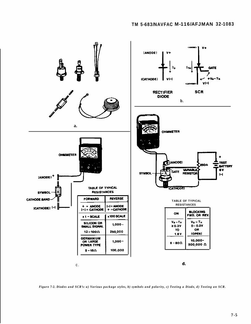
a.
TM 5-683/NAVFAC M-116/AFJMAN 32-1083
b.
TABLE OF TYPICALRESISTANCES
c.
Figure 7-2. Diodes and SCR’s: a) Various package styles, b) symbols and polarity, c) Testing a Diode, d) Testing an SCR.
7-5
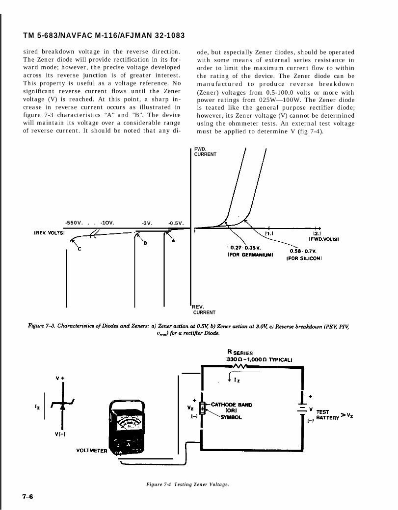
TM 5-683/NAVFAC M-116/AFJMAN 32-1083
sired breakdown voltage in the reverse direction.The Zener diode will provide rectification in its for-ward mode; however, the precise voltage developedacross its reverse junction is of greater interest.This property is useful as a voltage reference. Nosignificant reverse current flows until the Zenervoltage (V) is reached. At this point, a sharp in-crease in reverse current occurs as illustrated infigure 7-3 characteristics “A” and "B". The devicewill maintain its voltage over a considerable rangeof reverse current. It should be noted that any di-
-550V. . . -1OV. -3V. -0.5V.
I
ode, but especially Zener diodes, should be operatedwith some means of external series resistance inorder to limit the maximum current flow to withinthe rating of the device. The Zener diode can bemanufactured to produce reverse breakdown(Zener) voltages from 0.5-100.0 volts or more withpower ratings from 025W—100W. The Zener diodeis teated like the general purpose rectifier diode;however, its Zener voltage (V) cannot be determinedusing the ohmmeter tests. An external test voltagemust be applied to determine V (fig 7-4).
FWD.CURRENT
REV.CURRENT
Figure 7-4 Testing Zener Voltage.
TM 5-683/NAVFAC MO-116/AFJMAN 32-1083
f. Transistors. Transistors are three terminal,solid state devices constructed so that the currentacross the base-emitter junction will control agreater amount of current crossing the collector-emitter junction. Because a smaller current cancontrol a larger one, the transistor provides gain oramplification. Transistors vary in size, power, andvoltage ratings. Some idea of the electrical values,type, and application of the transistor in the circuitshould be known before testing is attempted.
(1) Testing. The bipolar junction transistor(BJT) is tested just like the general purpose rectifierdiode. These transistors are actually two diode junc-tions combined in such a way as to obtain currentcontrol. General purpose transistor testing is doneas follows (fig 7-5):
(a) Check the polarity of the test leads andzero the ohmmeter.
(b) Determine the type of transistor to betested, that is whether it is a positive, negative,positive (PNP) or a negative, positive, negative(NPN) junction type.
(c) Set the scale multiplier to “X1” or “L0”and recheck for zero ohms.
(d) Test all combinations as shown in thediagrams and tables given in figure 7-5a or 7-5b.
(e) Test all combinations as shown with thescale multiplier set to "X100” or “H1”. If the valuesshown in the tables are not obtained, the transistorpart number should be checked to confirm its type,or the unit should be replaced if the type is knownto be correct.
g. Other solid-state devices. There are numerousother types of solid-state devices used in modernelectronic and control systems. Most of these cannotbe statically tested with an ohmmeter and ex-pected to give meaningful results. The following is abrief list of devices that yield valid test results onlyin a circuit:
(1) Field-effect transistors (FETs), metal-oxidesemiconductor field-effect transistors (MOSFETS),or insulated-gate field-effect transistors (IGFETs).
(2) Unijunction Transistors (UJTs) or Program-mable Unijunction Transistors (PUTs).
(3) Analog Operational Amplifiers and Inte-grated Circuits.
(4) Any class of Digital Logic Integrated Cir-cuit.
7-3. Electrical disturbances (power quality).
Equipment with sensitive electronic circuits (digitalclocks, VCRs, computers, data terminals) may expe-rience memory loss, system malfunction and evencomponent failure due to electrical power sourcedisturbances. Sags, surges and harmonics are somecommon types of disturbances. Disturbances caused
by other customers or even by customer’s ownequipment may also affect customer’s equipment.“Power quality” is a relatively new term used todescribe the quality of power (absence of voltagedips, surges, harmonics outages, frequency varia-tion) at the user’s location. Traditional measure-ments for reliability studies don’t deal with thepower quality needs of sensitive electronic equipment. Rather, they deal with the permanent or pro-longed outage and how to improve upon it. Whilethis is indeed important to sensitive loads, there isincreased concern for short term or momentary dis-turbances. In addition to voltage limits, sensitiveloads such as computers typically require the fre-quency to be within plus or minus .05 Hz, the rate of change offrequency less than 1 Hz/sec, voltage waveform dis-tortion under five percent and voltage unbalanceless than three percent. For specific applications,the power quality requirements should be obtainedfrom the manufacturer of the sensitive equipment.Some of the common types of disturbances, thesymptoms, causes and effects are summarized intable 7-1.
7-4. Disturbance measurement and monitor-ing.
Conditions may be quite different at any given site,and it is desirable to obtain specific data about theactual situation, if possible, before considering aremedy. If it is an existing site, it is useful to obtainany historical data which might correlate sensitiveequipment operation with power disturbances. Thetype of data includes the sensitive equipment oper-ating log and maintenance records, and electric util-ity operating log and voltage recordings.
a. The most useful activity for any existing site isto conduct a site power line disturbance study for aone or two month period-including the storm sea-son, if possible. The monitoring should be at thesame point that powers the sensitive equipmentand must use equipment capable of recording thetypes of transients that can affect sensitive loads.
b. There are several types of equipment designedto perform this monitoring function. Unlike the tra-ditional strip or circular chart recorders, this equip-ment is capable of recording variations of voltage inthe short time periods of interest for sensitiveequipment, yet operate continuously for weeks at atime. Much of the equipment is of the digital read-out type which, unfortunately, can lead to improperinterpretation of the conditions at the site becauseit cannot always distinguish between harmless andharmful disturbances.
c. Much more useful monitors produce an analogrecording of the disturbances with the ability toexpand the waveforms to examine them in detail.
7-7

TM 5-683/NAVFAC M-116/AFJMAN 32-1083
Ip]“ I n
Figure 7-5. Transitor Testing: a) PNP type, b) NPN type.
With this data, it is possible to determine if a dis- 7-5. Voltage surge suppression.turbance is harmful or not by comparing it withspecific tolerance requirements for the sensitiveequipment actually used on site. This tolerance in-formation is generally available from sensitiveequipment manufacturers upon customer request.With the expanded waveform capability, it is oftenpossible to examine transients and observe a char-acteristic “signature” which will identify the sourceof the disturbance.
Voltage surges on a power system are a commonpower problem experienced by sensitive electronicequipment and mostly seen by the computer user.These transients can be the cause of lost data, falsetriggering and equipment failure. These transientsare generated both internally by the user and exter-nally on the utility primary due to lightning andequipment switching. Many different types of volt-
7-8

TM 5-683/NAVFAC MO-116/AFJMAN 32-1083
Table 7-1. Power quality problems summary.
7-9
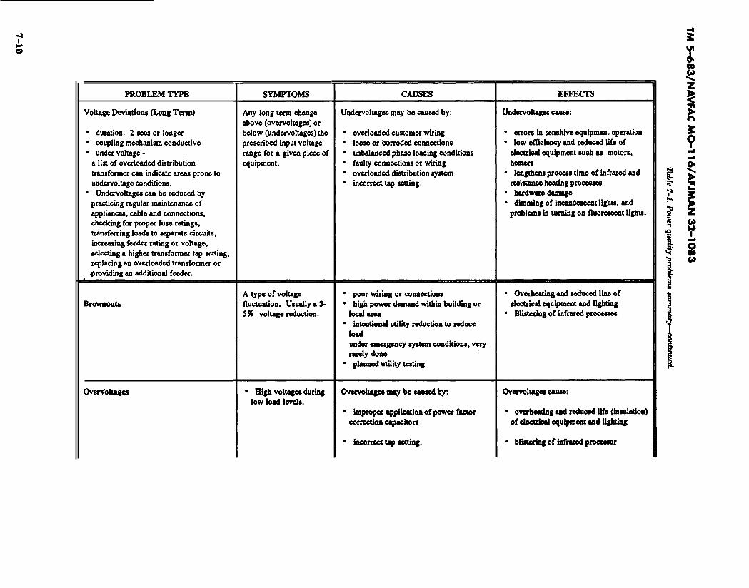

,‘/.,.
● Sags -
.●
●
●
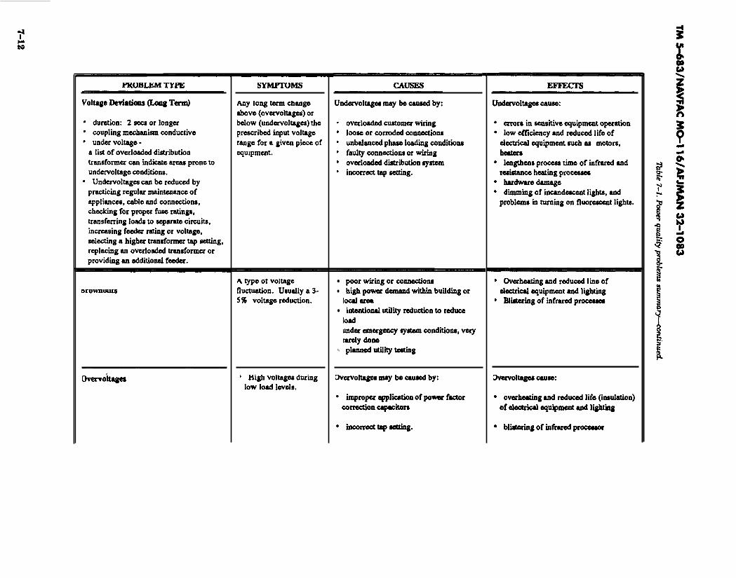
●
●
●
✎

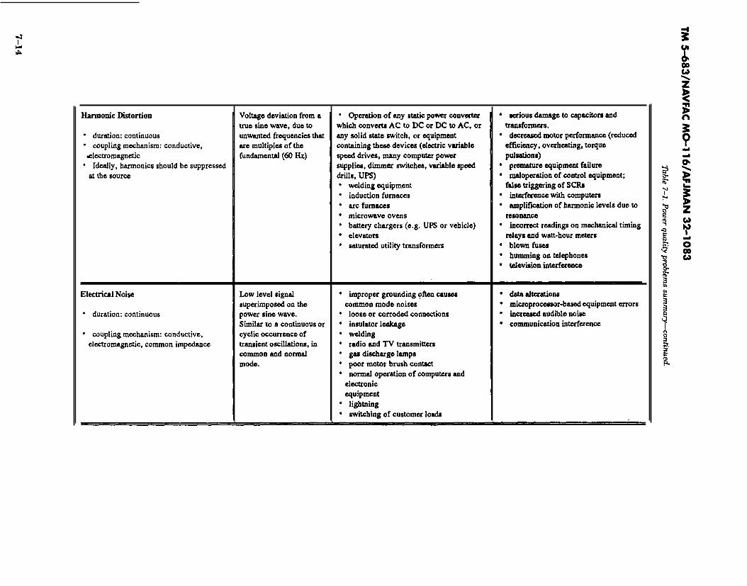

TM 5-683/NAVFAC MO-116/AFJMAN 32-1083
age suppressors, filters, etc. are used to protect thesensitive electronic equipment. These types ofequipment are called power conditioners.
a. Transient suppressors. Transient suppressorsare very low cost devices available for microcomput-ers in the form of outlet strips similar to extensioncords with multiple receptacles. They usually con-tain metal oxide varistors (MOVS) and sometimessilicon avalanche diodes (SADS). These are typicallydisc shaped devices connected between the powerlines and, sometimes, from line to ground. Theyabsorb energy from transients which exceed theirthreshold (typically 100 percent above normal peakvoltage). Because of their small size and low costcompared with the equipment they serve and thecost of determining if such transients exist at agiven installation, many people provide this protec-tion as insurance. This type of transient suppres-sors can be provided for a nominal cost and most ofthe more expensive power conditioners such as linevoltage regulators, static switches and UPS systemshave these devices built in. They can even be addedto a distribution panelboard, if not included else-where. Another form of transient suppressor, asurge arrester, is intended to lower the transientenergy level to that which can be handled by down-stream power conditioners, such as MOVS or filters.They typically use gas discharge tubes which areslower acting than MOVS, but can absorb more en-ergy. To be effective, however, they too must becoordinated with upstream surge arresters havinggreater energy absorbing capability. Usually, this isdone at each point of voltage transformation back tothe incoming line and is best coordinated with theelectric utility. Packaged transient suppressor sys-tems combining the devices described above areavailable which, when properly installed, will limitexpected surges as defined by the IEEE StandardC62.41.
b. Filters. Line filters are used to reduce electro-magnetic interference (EMI) and/or radio frequencyinterference (RFI) to acceptable levels. Generallysmall and low in cost, they, too, are usually builtinto sensitive equipment and the more expensivepower conditioner equipment. The simplest form offilter, a low pass filter, is designed to pass 60 Hzvoltage but to block the very high frequencies orsteep wavefront transients. They are not effectivefor frequencies near 60 Hz, such as low order har-monics, but become effective in the Khz range. Fil-ters can be connected line to line or line to neutralfor rejection of normal mode noise. They can also beconnected line to ground for common mode noiserejection. Some of the better transient suppressoroutlet strips also contain these falters.
7-16
c. Isolation transformers. Isolation transformersare more expensive power conditioners. They pro-vide two functions. One is the ability to change to anew voltage level and/or to compensate for high orlow site voltage. For example, by using 480V inputup to the point of use and then transforming to120V or 208Y/120V, the switchgear and wiring canbe reduced in size and the effect of line drop re-duced. If the voltage at the point of use is too lowdue to line drop, it can be manually boosted in stepsby connecting to different taps on the transformerwindings. The second function of the isolationtransformer is to provide for the ground referenceright at the point of use. This eliminates the prob-lem of common mode noise induced through “groundloops” or multiple current paths in the ground cir-cuit upstream of the established reference groundpoint.
d. Voltage regulators. Most of the voltage prob-lems except outages can be handled by the additionof voltage regulators equipped with transient sup-pressors. Several solid-state techniques have beendeveloped in recent years to replace the older, slowacting electro-mechanical type. One type of fast re-sponse regulator is the phase modulating type. Itusually utilizes thyristor (SCR) control of buck andboost transformers in combination with filters toprovide stable sinusoidal output even with non-linear loads typical of computer systems. This isdone in a smooth continuous manner, but at greatspeed, eliminating the steps inherent in the tapchanger. Heavy loads can be delivered for start-upinrush typical of computer central processors or discdrive motors while maintaining full voltage.
e. Motor generators. Motor generators consist ofan electric motor driving an AC generator so thatthe load is electrically isolated from the power line.Motor generators are used widely as a source of 400Hz power for large computer central processors re-quiring this frequency. Because the frequency toler-ance of the computers is wide, a simple inductionmotor can be used to drive a brushless synchronousgenerator (alternator). The speed changes with loadand input voltage variations hold output frequencywell within tolerance and constant voltage is main-tained by automatic voltage regulators controllingthe generator’s field excitation.
f. Uninterruptible power supplies (UPS). For con-tinuous operation of computer or other sensitivesystems when line voltage is interrupted, the onlysolution is a UPS. A properly designed UPS canprovide computer quality power under essentiallyall normal and abnormal utility power conditionsduring outages for extended period of time depend-ing on battery capacity. This bridges most poweroutages and permits orderly shutdown for longer

I TM 5-683/NAVFAC MO-116/AFJMAN 32-1083
outages. UPS systems are typically solid-state with- ous power. These systems are commonly known asout any rotating machinery. However, some designs rotary UPS. A rotary UPS electrical output is usu-incorporate motor generator sets in addition to ally more sinusoidal than a solid-state UPS and issolid-state circuitry and batteries to supply continu- less susceptible to distortion.
7-17

TM 5-683/NAVFAC MO-116/AFJMAN 32-1083
CHAPTER 8
GROUNDING
8-1. Ground maintenance.
The term grounding implies an intentional electri-cal connection to a reference conducting body, whichmay be earth (hence the term ground), but moregenerally consists of a specific array of intercon-nected electrical conductors. The resulting circuit isoften referred to by several terms, such as: groundplane, ground grid, mat or ground system. Ground-ing systems should be serviced as needed to ensurecontinued compliance with electrical and safetycodes, and to maintain overall reliability of the fa-cility electrical system. Action must be initiated andcontinued to remove, or reduce to a minimum, thecauses of recurrent problem areas. When possible,maintenance inspections should be performed attimes which have the least affect on user activities.The complexity of ground systems and the degree ofperformance expected from such systems is growingall the time. Maintenance or shop personnel areencouraged to become familiar with Article 250 ofthe National Electrical Code (NEC), which dealswith grounding requirements and practices.
8-2. Types of grounding systems.
Six (6) types of grounding systems will be described.They are static grounds, equipment grounds, sys-tem grounds, lightning grounds, electronic (includ-ing computer) grounds and maintenance safetygrounds. All of these systems are installed similarly.However, their purposes are quite different. Some ofthe systems carry little or no current with no freedfrequency. Others carry small to moderate currentsat 50 or 60 Hz. Still others must be able to carrycurrents over a very broad range of frequencies inorder to be considered effective. Most groundingsystem troubles are caused by one of two prob-lems: 1) loss of effectiveness due to poor mainte-nance and, 2) inadequate ground system for thedegree of performance expected.
a. Static grounds. A static ground is a connectionmade between a piece of equipment and the earthfor the purpose of draining off static electricitycharges before a spark-over potential is reached.The ground is applied for more than just the com-fort of the equipment operator. The possibility of anexplosion ignited by an electrical spark must beconsidered. Dry materials handling equipment,flammable liquids pumps and delivery equipment,plastic piping systems, and explosives storage areasall need static ground protection systems installed
and functioning properly. Static ground systems aregenerally not called upon to conduct much currentat any given frequency. Smaller gauge, bare conduc-tors, or brushes with metallic or conductive bristlesmake up most parts of the static ground system.
b. Equipment grounds. An equipment groundpertains to the interconnection and connection toearth of all normally non-current carrying metalparts. This is done so the metal parts with which aperson might come into contact are always at ornear zero volts with respect to ground thereby pro-tecting personnel from electric shock hazards.Equipment grounding consists of grounding allnoncurrent-carrying metal frames, supports and en-closures of equipment. All these metallic parts mustbe interconnected and grounded by a conductor insuch a way as to ensure a path of lowest impedancefor the flow of ground fault current from any line toground fault point to the terminal at the system’ssource. An equipment grounding conductor nor-mally carries no current unless there is an insula-tion failure. In this case the fault current will flowback to the system source through the equipmentgrounding conductors to protect personnel fromelectrical shock. The equipment grounding conduc-tor must never be connected to any other hot lines.Equipment grounding systems must be capable ofcarrying the maximum ground fault current ex-pected without overheating or posing an explosionhazard. Equipment grounds may be called upon toconduct hundreds to thousands of amperes at theline frequency during abnormal conditions. The sys-tem must be sized and designed to keep the equip-ment surface voltages, developed during such ab-normal conditions, very low. An example of thissystem is the bare copper wire (green conductor)connected to the frames of electric motors, breakerpanels, outlet boxes, etc., see figure 6-1 for typicalequipment grounding. Electrical supporting struc-tures such as metal conduit, metal cable trays ormetal enclosures should be electrically continuousand bonded to the protective grounding scheme.Continuous grounding conductors such as a metallicraceway or conduit or designated ground wiresshould always be in from the ground grid system todownstream distribution switchboards to ensureadequate grounding throughout the electrical distri-bution system. A typical grounding system for abuilding containing significant electrical equipmentand related apparatus is shown in figure 8-2, Theillustration shown depicts three most commonly en-
8-1

TM 5-683/NAVFAC M-116/AFJMAN 32-1083
countered areas pertaining to the grounding. Thegrounding grid and grounding body (earth underthe building) with the ground rods (electrodes andthe water pipe system) are shown. The second partis the conductors associated with the equipmentground. Part of the equipment ground is alsoformed by the switchgear ground bus.
c. System grounds. A system ground refers to thecondition of having one wire or point of an electricalcircuit connected to earth. This connection point isusually made at the electrical neutral although notalways. The purpose of a system ground is to protectthe equipment. This ensures longer insulation lifeof motors, transformers and other system compo-nent A system ground also provides a low imped-ance path for fault currents improving ground faultrelaying selectivity. In a properly grounded systemthe secondary neutral of a power transformer sup-plying a building or facility is connected to a trans-former grounding electrode. The transformer neu-tral is a part of the service entrance point whichbonds to the grounding electrode system of thebuilding. According to the National Electrical Code(NEC) articles 250-81 and 250-83, metal under-ground waterpipes, metal building frames, encasedelectrodes, rods and plates are among the itemsthat can make up the grounding electrode system ofa building. The NEC article 250-S3 requires thatthe size of the grounding electrode iron or steel rodmust be at least 5/8 inches in diameter and driveneight feet deep. The resistance of the electrode toground cannot exceed 25 ohms (NEC 250-84). Oth-erwise a second electrode should be added and thedistance between the two electrodes must be atleast six feet. However, in some systems the 25ohms resistance value cannot achieve the goals ofgrounding. They require ground resistance valuesbelow ten ohms. According to MIL-STD-l88-12Aten ohms ground resistance is acceptable. If themain building load is composed of computers orsensitive electronic equipment, the earth ground re-sistance should not exceed five ohms. There aremany methods of system grounding used in indus-trial and commercial power systems, the major onesbeing ungrounded, solid grounding, and low andhigh resistance grounding (fig 8-3). Technically,there is no general acceptance to use any one par-ticular method. Each type of system grounding hasadvantages and disadvantages. Factors which influ-ence the choice of selection include voltage level ofthe power system, transient overvoltage possibili-ties, types of equipment on the system, cost ofequipment, required continuity of service, quality ofsystem operating personnel and safety consider-ation including fire hazards.
8-2
(1) Ungrounded system. An ungrounded sys-tem is one in which there is no intentional connec-tion between the neutral or any phase and ground.Ungrounded system implies that the system iscapacitively coupled to ground. The neutral poten-tial of an ungrounded system under reasonably bal-anced load conditions will be close to ground poten-tial because of the capacitance between each phaseconductor and ground. When a line-to-ground faultoccurs on an ungrounded system, the total groundfault current is relatively small, but the voltages toground potential on the unfaulted phases will behigh. If the fault is sustained, the normal line-to-neutral voltage on the unfaulted phases is increasedto the system line-to-line voltage (i.e. square root ofthree (3) times the normal line-to-neutral value).This, over a period of time, breaks down the line-to-neutral insulation and hence results in insulationfailure. Ungrounded system operation is not recom-mended because of the high probability of failuresdue to transient overvoltages caused by restrikingground faults. The remaining various groundingmethods can be applied on system grounding pro-tection depending on technical and economic fac-tors. The one advantage of an ungrounded systemthat needs to be mentioned is that it generally cancontinue to operate under a single line-to-groundfault without an interruption of power to the loads.
(2) Solidly grounded system. A solidlygrounded system is one in which the neutral (oroccasionally one phase) is connected to ground with-out an intentional intervening impedance (fig 8-4).On a solidly grounded system in contrast to an un-grounded system, a ground fault on one phase willresult in a large magnitude of ground current toflow but there will be no increase in voltage on theunfaulted phase. Solid grounding is commonly usedin low voltage distribution systems. Solid groundinghas the lowest initial cost of all Wounding methods.It is usually recommended for overhead distributionsystems supplying transformers protected by pri-mary fuses. However, it is not the preferred schemefor most industrial and commercial systems, againbecause of the severe damage potential of high mag-nitude ground fault currents. The NEC Article250-5 (1990) requires that the following classes ofsystems be solidly grounded:
(a) Where the system can be so groundedthat the maximum voltage to ground on the un-grounded conductors does not exceed 150 volts.
(b) Where the system is 3-phase, 4-wire,wye-connected in which the neutral is used as acircuit conductor.
(c) Where the system is 3-phase, 4-wiredelta-connected in which the midpoint of one phaseis used as a circuit conductor.

TM 5-683/NAVFAC M-116/AFJMAN 32-1083
PHASE
Figure 8-1. Typical Equipment Ground.

TM 5-683/NAVFAC MO-116/AFJMAN 32-1083
Figure 8-2. Typical grounding system for a building and its apparatus.
(d) Where a grounded service conductor isuninsulated in accordance with the NEC Exceptionsto Sections 230-22, 230-30 and 230-41.
(3) Resistance grounded system. Limiting theavailable ground fault current by resistancegrounding (fig 6-5) is an excellent way to reducedamage to equipment during ground fault condi-tions, and to eliminate personal hazards and electri-cal fire dangers. It also limits transient overvoltagesduring ground fault conditions. The resistor canlimit the ground fault current to a desired levelbased on relaying needs. At the occurrence of aline-to-ground fault on a resistance grounded sys-tem, a voltage appears across the resistor whichnearly equals the normal line-to-neutral voltage ofthe system. The resistor current is essentially equalto the current in the fault. Therefore, the current ispractically equal to the line-to-neutral voltage di-
8-4
tided by the number of ohms of resistance used. Thegrounding resistances are rated in terms of currentand its duration for different voltage classes.
(a) Low resistance grounding. Low resistancegrounding refers to a system in which the neutral isgrounded through a small resistance that limitsground fault current magnitudes. The size of thegrounding resistor is selected to detect and clear thefaulted circuit. Low resistance grounding is not rec-ommended on low-voltage systems. This is primar-ily because the limited available ground fault cur-rent is insufficient to positively operate series tripunits and fuses. These trip units and fuses would bedependent upon both phase-to-phase and phase-to-ground fault protection on some or all of the distri-bution circuits. Low resistance grounding normallylimits the ground fault currents to approximately100-600A. The amount of current necessary for se-

TM 5-683/NAVFAC MO-116/AFJMAN 32-1083

Figure 8-4. Methods of solidly grounding the neutral of three-phase systems.
GENERATORNEUTRAL
POWERTRANSFORMER
NEUTRAL
GROUNDINGTRANSFORMER
NEUTRAL
TM 5-683/NAVFAC M-116/AFJMAN 32-1083
lective relaying determines the value of resistanceto be used.
(b) High resistance grounding. High resis-tance grounding refers to a system in which theneutral is grounded through a predominantly resis-tive impedance whose resistance is selected to allowa ground fault current through the resistor equal toor slightly more than the capacitive charging cur-rent of the system. Because grounding through ahigh resistance entails having a physically largeresistance that is both bulky and costly, high resis-tance grounding is not practical and is not recom-mended. However, high resistance groundingthrough a grounding transformer is cost effectiveand accomplishes the same objective. High resis-tance grounding accomplishes the advantage of un-grounded and solidly grounded systems and elimi-nates the disadvantages. It limits transientovervoltages resulting from a single phase-to-ground fault by limiting ground fault current toapproximately 8A This amount of ground fault cur-rent is not enough to activate series overcurrentprotective devices, hence no loss of power to down-stream loads will occur during ground fault condi-tions. Special relaying must be used on a high resis-tance grounded system in order to sense that aground fault has occurred. The fault should then belocated and removed as soon as possible so that ifanother ground fault occurs on either of the twounfaulted phases, high magnitude ground fault cur-rents and resulting equipment damage will not oc-cur. High resistance grounding is normally appliedin situations where it is essential to prevent un-planned system power outages, or previously thesystem has been operated ungrounded and noground relaying has been installed. Once theground point has been established through the re-sistor, it is easier to apply protective relays. Theuser may decide to add a ground overcurrent relayANSI/IEEE device 50/51G. The relay maybe eithercurrent actuated using a current transformer orvoltage actuated using a potential transformer. De-pending on the priority of need, high resistancegrounding can be designed to alarm only or providedirect tripping of generators off line in order toprevent fault escalation prior to fault locating andremoval. High resistance grounding (arranged toalarm only) has proven to be a viable groundingmode for 600V systems with an inherent total sys-tem charging current to ground (31CO) of about5.5A or less, resulting in a ground fault current ofabout 8A or less. This, however, should not be con-strued to mean that ground faults of a magnitudebelow this level will always allow the successfullocation and isolation before escalation occurs.Here, the quality and the responsiveness of the
plant operators to locate and isolate a ground faultis of vital importance. To avoid high transientovervoltages, suppress harmonics and allow ad-equate relaying, the grounding transformer and re-sistor combination is selected to allow current toflow that equals or is greater than the capacitivechanging current.
d. Lightning grounds. Lightning grounds are de-signed to safely dissipate lightning strokes into theearth. They are part of a lightning protection sys-tem which usually consists of air terminals (light-ning rods), down conductors, arresters and otherconnectors of fittings required for a complete sys-tem. A lightning protection system’s sole purpose isto protect a building, its occupants and contentsfrom the thermal, mechanical and electrical effectsof lightning. Effective grounding for lightningstrokes is sometimes difficult to achieve because itis nearly impossible to predict the maximum dis-charge current. Currents from direct strikes canreach magnitudes of 100,000 amperes or more withfrequencies of tens to hundreds of kilohertz. Fortu-nately, the event is very short, thus allowing mostproperly sized and maintained systems to survivethe "hit".
(1) Requirements. Main lightning protection re-quirement is dependent upon the height of thebuilding. According to NFPA 78-1986, there are twoclassifications for a building. Class I is a buildingwith less than 75 feet height. The Class II buildingis higher than 75 feet or has a steel frame with anyheight. For further information about the lightningprotection code see NFPA 78-1986 which containsmore detail.
e. Electronic and computer grounds. Groundingfor all electronic systems, including computers andcomputer networks, is a special case of the equip-ment ground and the system ground carefully ap-plied. In fact, grounding systems for electronicequipment are generally the same as for systemground with an additional requirement: the degreeof performance required. Electronic equipmentgrounding systems must not only provide a meansof stabilizing input power system voltage levels, butalso act as the zero voltage reference point. How-ever, the need to do so is not restricted to a lowfrequency of a few hundred hertz. Grounding sys-tems for modem electronic installations must beable to provide effective grounding and bondingfunctions well into the high frequency megahertzrange. Effective grounding at 50-60 Hz may not beeffective at alI for frequencies above 100 kilohertz.
(1) Requirements. There are several aspects tothe requirement for good grounding performance forelectronic equipment; all of which are due to electri-cal circuit behavior. Digital systems operate at high
8-7

TM 5-683/NAVFAC MO-116/AFJMAN 32-1083
frequencies. Modem systems achieve clock and datarates at 4 megahertz and higher. Clock rate is therate at which a word or characters of a word (bits)are transferred from one internal computer elementto another. Data rate is the rate at which data istransferred (bauds or bits per second) between com-puters. At these frequencies, due to the impedance,a regular ground wire acts as conductor for only afew feet. Compare the frequency and wavelength ofthese systems with those used for 60 Hz power.Electricity is conducted on a wire at very nearly thespeed of light (186,000 miles/sec.). Dividing thespeed by the frequency gives the full wavelength.For 60 Hz, one wavelength is about 3,100 miles.Communications and radar personnel know that in-teresting things begin to happen at one fourth of thewavelength. The voltage and the current no longerhave the same relationship at this point on the wire.The quarter wavelength for 60 Hz is about 775miles. However, the quarter wavelength for tenmegahertz is only 24.5 feet. This is not the worstcase; the change in the current and voltage relation-ship along a wire occurs gradually over the distancetravelled. To maintain a close relationship betweenthe voltage and current at all points along the con-ductor’s path, it cannot be much longer than l/20thof a wavelength. Therefore, effective ground conduc-tor length for a ten megahertz signal is only about4.9 feet. This does not mean electronic groundingsystems cannot be longer than four or five feet. Theimportant conductor is the equipment grounding(bonding) conductor, which may be a copper cable,strap, sheet, or braid. It is this particular conductorwhich limits how far the electronic or computerequipment may be placed from the signal referencegrid (equipotential plane) or system.
(2) Noise interference. Coupled and inducedelectrical noise is also a problem at higher fre-quencies. This effect is rarely a concern for systemsoperating at the 60 Hz powerline frequency. Verylittle, if any, current is induced or coupled to theground conductors at low frequency. At high fre-quency, relatively more current is induced into theground conductors through shields, cable trays, con-duit, and the enclosures used to house the electronicsystem- As a result, these conductors must dealwith more noise current than 60 Hz systems. Inaddition, they must hold the reference voltage verynear zero at all points on the equipotential system.
(3) Power system grounding. The input powersystem ground resistance is important because itkeeps the system voltage at nominal values. This“resistance” is not only a simple resistance measure-ment but also a frequency dependent impedancemeasurement. The best test instruments (para14-5) actually apply an alternating current which
returns a measurement of the conductors’ induc-tance plus the grounding system’s contact resis-tance. If the ground resistance reading is high atthe low frequencies applied by test instrument, itwill be much higher at the higher frequencies. Themanufacturers of some electronic systems call forsystem grounding resistance of one ohm or less.This low resistance is many times more difficult toachieve than the 25 ohm maximum grounding resis-tance of a made electrode for power systems (NECarticle 250-84). To put that in perspective; aircraftdo not maintain an earth ground, but do maintain alow impedance between on-board electronic devicesby using the aircraft skin and framework as a zerovoltage equipotential plane.
(4) Loop-flow. A low resistance to ground in theinput power system is no promise of trouble-freeperformance. It is necessary to understand that theearth is not a magic dumping area where unwantedsignals and currents simply disappear. Currents al-ways flow in complete circuit loops that may includevarious portions of the earth, the grounding elec-trodes, the grounding conductors, equipment bonds,and the equipment enclosures.
(5) Isolated ground system. Loop currents flow-ing through one portion of the earth into anotherusually include a substantial amount of inducedhigh frequency common mode noise. Many design-ers have tried to solve the noise problem with asingle point, isolated ground system. This systemuses an insulated ground wire from the load to theservice entrance panel board. All isolated groundoutlets are of a special design such that the groundwire is isolated from the normal connections to themetal mounting frame and electrical outlet box. Theisolated ground system is actually a very high im-pedance at high frequencies. This high impedancedoes attenuate this noise, but causes problems ashigh frequency voltages build up over its length,due to the high frequency current through the im-pedance of the conductor (IZ). Most manufacturersnow include surge protection with their isolatedground receptacles to protect the equipment fromthe high voltages that develop at high frequenciesacross these types of receptacles (common andtransverse mode). All exposed metal parts still re-quire the equipment ground conductor. Therefore,two ground conductors are required: the equipmentsafety (“dirty”) ground, and the isolated system(“clean”) ground. All of the equipment grounds arerouted and bonded in the normal way. All isolatedground conductors must be brought back to onepoint in the subpanel. The subpanel isolated groundbus must not be bonded to the subpanel enclosure.This ground bus must be isolated and only con-nected with insulated conductor(s) to the service

TM 5-683/NAVFAC M-116/AFJMAN 32-1083
entrance ground bus. The input power system neu-tral must also be grounded only at the service en-trance. The isolated ground system stops loop cur-rents and common mode electrical noise, but hasseveral major disadvantages: The long branchfeeder and isolated ground conductors are effectiveonly for low data transfer frequencies (fig 8-6c.High voltages occur between the conductors duringsurges. It is also a very difficult system to inspectand maintain. Frequency inspections must be madeto ensure the system has not been defeated by inad-vertent or deliberate installation of a jumper orconductor between the two systems. Inspectionsand tests on this type of grounding must be carriedout after each electrical system modification. It isbest not to use isolated ground systems at all unlessforced to by the equipment manufacturers. It is alsobest to restrict such systems to small areas or onlyone floor of the building.
(6) Electronic system grounding. Good elec-tronic system grounding performance is achievedwith a properly laid out distribution of multipoint,well-bonded grounding connections. This systemcan use bare, braided, sheet, or stranded copperconductors for grounding or bonding functions. Thissystem requires conduit and equipment enclosurebonding at all junction points. In other words,simple metallic contact between the enclosures, wir-ing conduits, and power panels is not enough. Themultipoint bonding provides low impedance ground-ing for the electronic equipment. The low imped-ance between the separate items of electronic equipment keeps the noise voltages at or near zerobetween them and, therefore, provides an“equipotential plane”. This system is much easier toinspect and test. No special requirements must bemet during modifications or expansion of the elec-trical system. All power panels and all supply trans-formers feeding an installation with this type ofgrounding system must be grouped and bonded to-gether using short lengths of bare, braided, sheet, orstranded copper conductors in order to achieve theeffective high frequency grounding performance de-scribed above. As shown in figure 8-6d, a singlearea of power entry with a large equipotentialground plane and short equipment grounding con-ductors forms the preferred grounding system forlarge automated data processing (ADP) and com-puter applications.
f. Maintenance safety grounds. Grounds used formaintenance work are usually intentional, but tem-porary, connections between equipment power con-ductors and ground. These connections are alwaysapplied after the power source has been turned offand the circuit(s) have been tested and are known tobe de-energized. The ground is intended to protect
maintenance personnel from an inadvertent re-energization of the circuit. The ground is removedtier maintenance operations have been completed.Application of a maintenance ground is discussed inmore detail in paragraph 12-2d.
g. Ground system tests. Periodic testing should bedone to assure grounding system effectiveness. Thefollowing are points that should be addressed dur-ing inspection and maintenance:
(1) Inspect and test single point, isolatedground systems after every electrical system modi-fication. visually inspect outlets and panels for con-ductors forming loops between the equipmentground and the isolated ground.
(2) Test the ground to neutral voltage at eachpower distribution panel included in the particularsystem. The voltage should be taken using a highimpedance AC voltmeter and an accurate recordshould be kept. The voltage should be very low; onthe order of l0-150 millivolts (0.01-0.150V). Anysudden changes or increasing trends should be in-vestigated and the cause corrected.
(3) The made electrode, rod, plate, or selectedground body contact point should be tested every12-24 months. A record should be kept. Any increas-ing impedance indicates need for remedial action.
8-3. Ground fault interrupting methods.
Ground faults result when an electrical componentsinsulation deteriorates allowing an above normalcurrent leakage to ground. Minute current leakagemay normally occur from virtually every electricaldevice. Ground faults become dangerous when anunintended ground return path becomes estab-lished. This ground return path could be throughthe normal electrical components and hardware(equipment ground for instance), conductive mate-rial other than the system ground (metal, water,plumbing, pipes, etc.), a person or, any combinationof the above. Ground fault leakage currents of muchlower levels than is needed to trip conventional cir-cuit breakers can be hazardous. Therefore, to re-duce the possibility of fire, injury, or fatality, theNEC requires additional ground fault protection forcertain types of circuits. Ground fault protectivedevices are of two distinct types: ground fault cir-cuit interrupters and ground fault protectors. It isextremely important to understand the differencebetween them.
a. Ground fault circuit interrupters (GFI). A GFIis designed to protect a person from electrocutionwhen contact between a live part of the protectedcircuit and ground causes current to flow through aperson’s body. A GFI will disconnect the circuitwhen a current equal to or higher than the calibra-tion point (4 to 6 mA) flows from the protected
8-9

TM 5-683/NAVFAC MO-116/AFJMAN 32-1083
a.
b .
Figure 8-6. Grounding for Electronic and ADP Systems: a) Establish a central grounding point, b) Principal features of an isolatedgrounding system.
8-10

TM 5-683/NAVFAC MO-116/AFJMAN 32-1083
c.
and
200
PerspectiveSchematic
d.
Grounded by Gwen Wire Only
Figure 8-6. (Continued) Grounding for Electronic and ADP Systems: c) Avoid long runs of single grounding conductors, d) An effectivemulti-point grounding system for high frequencies, e) Comparison of single conductors us a multi-point grid at high frequencies.
8-11

TM 5-683/NAVFAC MO-116/AFJMAN 32-1083
circuit to ground (fig 8-6). It will not eliminate theshock sensation since the normal perception level isapproximately 0.5 mA. It will not protect from elec-trocution upon line-to-line contact since the natureof line-to-line loads cannot be distinguished by aline-to-ground device. GFIs are sealed at the fac-tory, and maintenance should be limited to thatrecommended by the manufacturer. Tripping testsshould be performed with the test button on theunit in accordance with the frequency recommendedby the manufacturer. Results and dates of testsshould be recorded on the test record label or cardsupplied with each permanently installed GFI unit.There are four types of GFIs. There are circuitbreaker type, receptacle type, portable type, andpermanently mounted type.
(1) Circuit breaker type. A circuit breaker typeGFI is designed in the form of a small circuitbreaker and is completely self-contained within theunit housing. The circuit breaker type GFI providesoverload and short-circuit protection for the circuitconductors in addition to ground-fault protection forpersonnel. It is intended to be mounted in apanelboard or other enclosure. For required mainte-nance refer to paragraph 5-4c.
(2) Receptable type. A receptacle type GFI is de-signed in the form of a standard receptacle that iscompletely self-contained within the unit housing,and does not provide overload or short-circuit protec-tion. It is intended for permanent installation in con-ventional device outlet boxes or other suitable enclo-sures. Maintenance required for a GFI receptacle isthe same as any standard receptacle outlet. If theGFI receptacle does not reset, is badly worn, cracked,or broken, or if contacts are exposed, the GFI must bereplaced. It should also be replaced if accidental dis-engagement of a plug from the receptacle is a recur-ring problem. Proper wire connections on the recep-tacle and proper polarity of power connections shouldbe checked including the integrity of the equipmentground. If there is abnormal heating on the GFIreceptacle face, check for loose terminal connectionsand correct or replace. If there is evidence of burningor arc-tracking, it should be replaced.
(3) Portable type. A portable type GFI is a unitintended to be easily transported and plugged intoany grounded receptacle outlet. Cords, tools or otherdevices to be provided with ground-fault protectionfor personnel are then plugged into receptaclesmounted in the unit. Required maintenance wouldinclude that recommended in paragraph (2) abovefor receptacle type GFIs along with the followingcord care recommendations:
(a) Keep the cord free of oil, grease and othermaterial that may ruin the rubber cover. Avoid tan-gling knots or dragging across sharp surfaces.
8-12
(b) Make sure that the power tool isgrounded through the additional grounding conduc-tor in the cord and the grounding prong of the plug.The integrity of this ground circuit is necessary forthe Protection of personnel.
(c) Make sure that the cord is not cut, bro-ken, spliced or frayed. Cords maybe replaced or thedamaged portion may be cut out and the two sec-tions rejoined by attaching a plug and connector.
(d) Make sure that the green conductor isconnected to the frame of the tool and the groundingprong of the attachment plug.
(4) Permanent type. A permanently mountedtype GFI is a self-contained, enclosed unit designedto be wall or pole mounted and permanently wiredinto the circuit to be protected. Maintenance beyondtightening of connections and cleaning should notbe attempted. Any repairs needed should be re-ferred to the manufacturer.
b. Ground fault protectors (GFP). A GFP is de-signed to limit damage to electrical equipment inthe event of a fault (either solid or arcing) between alive part of the protected circuit and ground. A GFPwill cause the circuit to be disconnected when acurrent equal to or higher than its setting flows toground (fig 8-7). GFPs are available with settingstypically ranging from five to 1200 amperes. It willnot protect personnel from electrocution. A GFP sys-tem is designed to be installed in a grounded distri-bution system. I t cons is ts o f three maincomponents: sensors; relay or control unit; and atripping means for the disconnect device controllingthe protected circuit. Detection of ground-fault cur-rent is done by either of two basic methods. Withone method, ground current is detected by sensingcurrent flow in the grounding conductor. With theother method, all conductor currents are monitoredby either a single large sensor, or several smallerones. Sensors are generally a type of current trans-former and are installed on the circuit conductors.The relay or control unit maybe mounted remotelyfrom the sensors or maybe integral with the sensorassembly. Circuit breakers with electronic trip unitsmay have a GFP system integral with the circuitbreaker. Any maintenance work performed on theelectronic circuitry should adhere to manufacturer’sinstructions. Maintenance on the mechanical oper-ating mechanism components should be performedas recommended in chapter 5. Maintenance require-ments for the sensors are as specified in chapter 2for instrument transformers. Tighten all terminalconnections and clean. Any repairs needed shouldbe performed by the manufacturer. If interconnec-tions between components are disconnected, theymust be marked and replaced to maintain theproper phasing and circuitry. If the system is
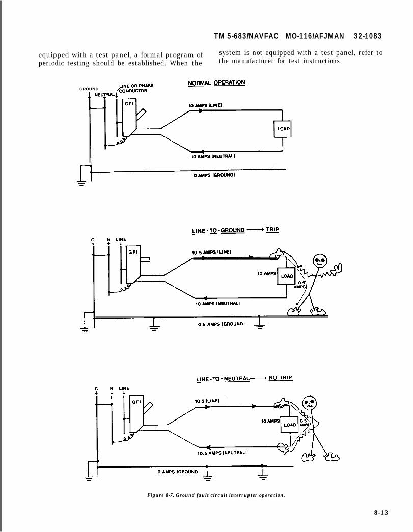
TM 5-683/NAVFAC MO-116/AFJMAN 32-1083
equipped with a test panel, a formal program of system is not equipped with a test panel, refer toperiodic testing should be established. When the the manufacturer for test instructions.
GROUND
Figure 8-7. Ground fault circuit interrupter operation.
8-13
TM 5-683/NAVFAC MO-116/AFJMAN 32-1083
CHAPTER 9
ILLUMINATION
9-1. Lighting maintenance.
Each lighting installation is designed to produce aspecific level of illumination adequate for thoseworking in the area. Adequate illumination shouldbe maintained to reduce eyestrain, improve morale,increase safety, improve housekeeping, decrease fa-tigue, reduce headaches and increase production,all of which are directly reflected in lower operatingcost. The maintenance of lighting systems is aimedat preserving the light producing capability at theoriginal design level. Its necessity cannot be over-emphasized. To prevent progressive deterioration ofthe system, prompt repair of any deficiency is essen-tial. Since dirt accumulating and lamp aging are thetwo major factors which reduce the light output, itis necessary that lamps, fixtures and reflective ar-eas be kept clean; defective lamps be replaced; andthe voltage be held stable.
9-2. Fluorescent lighting.
There are three principal types of fluorescent fix-tures; preheat, instant-start and rapid-start. Allhave practically the same physical dimensions butdifferent internal construction. A preheat fixturehas a ballast and starter which supplies nominalvoltage to the lamp (fig 9-l). These are older stylefixtures which cause the fluorescent tube to flickerbefore it lights. An instant-start fixture has a bal-last which supplies a high voltage to the fluorescenttube to light it instantly. A rapid-start fixture has aballast which requires a starting aid voltage be-tween the full length of the lamp and the groundedmetal surface of the fluorescent fixture. The type ofcircuit in which a particular lamp must be used isetched on the end of the lamp. For most applica-tions, the 4-foot rapid-start lamp is the preferredlamp. Energy efficient lamps and electronic ballastsare also available. They can replace standard fluo-rescent lamps and save electricity by providing full-light output at reduced wattage and operating tem-peratures. Electronic ballasts can save up to 25percent of the energy. The advantages of the elec-tronic ballast besides energy saving, are lighterweight, less humming noise, dimmable and capableof operating up to four lamps at a time. The Na-tional Electrical Code Article 410-73 requires thatall indoor fluorescent fixtures (except those withsimple reactance ballasts) incorporate Class p bal-lasts with integral thermal protection. This require-ment applies to all new installations and replace-
ments. Older models with simple (single winding)reactance ballasts are an exception. The NEC Ar-ticle 410-18(a) also requires that fluorescent fix-tures as well as all other lighting fixtures andequipment with exposed conductive parts begrounded. Failure to properly ground the ballastand fixture combination could result in shock haz-ard. In addition to a shock hazard, failure to prop-erly ground a fixture may result in frequent tubefailures and trouble with starting for certain de-signs. For relamping or lighting retrofit it is impor-tant to assure existing ballast is in compliance withthe new lamp. For example, when replacing a T-12with a T-8 lamp the new ballast for the T-8 shouldbe installed since the existing T-12 ballast is incom-patible although the lamp bases are similar.
9-3. Incandescent lighting.
In an incandescent lamp, light is generated by heat-ing the filament to incandescence. The hotter thefilament, the more efficient it is in converting elec-tricity to light. However, when the filament oper-ates hotter, its life is shortened. Therefore the de-sign of each lamp is a balance between efficiencyand life. Incandescent lighting fixtures are designedfor a particular lamp size and type. However, it ispossible to use much higher wattage lamps in afixture than the fixture or the circuit can ad-equately handle. The excessive heat of higher watt-age lamps can damage the sockets, increase failurerates and overload the circuits. Personnel are cau-tioned to use only the lamp size (in watts) recom-mended for the fixture or smaller rather than ahigher wattage lamp that may physically fit. Incan-descent lamps come in a variety of voltage ratings.For most applications, the lamp voltage rating near-est the available line voltage should be selected.Under this condition, the lamp will produce itsrated value of life, watts and light output. Energyefficient replacements are available for standard in-candescent lamps. They provide better lamp effi-ciency with no loss in lamp life. Many incandescentlamps are available with life ratings in excess ofordinary general service lamps. Some have ratingsof 5,000 hours or more and some even are guaran-teed to burn for five years. Use of these lamps maybe practical at locations where access is limited in-cluding high ceiling auditoriums, exit lights, stair-wells, and marker lights on towers or fire alarmboxes. Use of an ordinary general service lampwhose voltage rating is higher than the circuit volt-
9-1
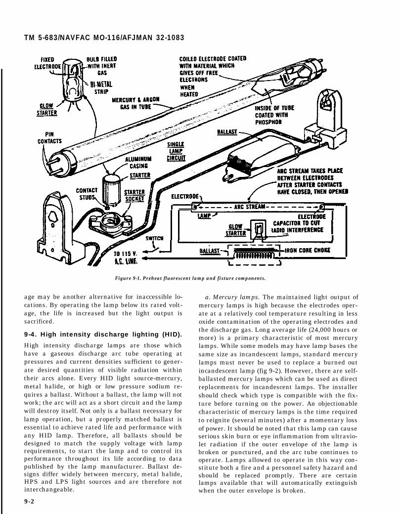
TM 5-683/NAVFAC MO-116/AFJMAN 32-1083
Figure 9-1. Preheat fluorescent lamp and fixture components.
age may be another alternative for inaccessible lo-cations. By operating the lamp below its rated volt-age, the life is increased but the light output issacrificed.
9-4. High intensity discharge lighting (HID).
High intensity discharge lamps are those whichhave a gaseous discharge arc tube operating atpressures and current densities sufficient to gener-ate desired quantities of visible radiation withintheir arcs alone. Every HID light source-mercury,metal halide, or high or low pressure sodium re-quires a ballast. Without a ballast, the lamp will notwork; the arc will act as a short circuit and the lampwill destroy itself. Not only is a ballast necessary forlamp operation, but a properly matched ballast isessential to achieve rated life and performance withany HID lamp. Therefore, all ballasts should bedesigned to match the supply voltage with lamprequirements, to start the lamp and to control itsperformance throughout its life according to datapublished by the lamp manufacturer. Ballast de-signs differ widely between mercury, metal halide,HPS and LPS light sources and are therefore notinterchangeable.
9-2
a. Mercury lamps. The maintained light output ofmercury lamps is high because the electrodes oper-ate at a relatively cool temperature resulting in lessoxide contamination of the operating electrodes andthe discharge gas. Long average life (24,000 hours ormore) is a primary characteristic of most mercurylamps. While some models may have lamp bases thesame size as incandescent lamps, standard mercurylamps must never be used to replace a burned outincandescent lamp (fig 9-2). However, there are self-ballasted mercury lamps which can be used as directreplacements for incandescent lamps. The installershould check which type is compatible with the fix-ture before turning on the power. An objectionablecharacteristic of mercury lamps is the time requiredto reignite (several minutes) after a momentary lossof power. It should be noted that this lamp can causeserious skin burn or eye inflammation from ultravio-let radiation if the outer envelope of the lamp isbroken or punctured, and the arc tube continues tooperate. Lamps allowed to operate in this way con-stitute both a fire and a personnel safety hazard andshould be replaced promptly. There are certainlamps available that will automatically extinguishwhen the outer envelope is broken.

TM 5-683/NAVFAC MO-116/AFJMAN 32-1083
Figure 9-2. Mercury lamp.
b. Metal halide lamps. Metal halide lamps re-semble mercury lamps in appearance and are usedsimilarly. The color produced is better than mercurylamps and control of the light is easier. The initialefficiency is also better for wattages above 150W.Otherwise mercury lighting is more efficient. Disad-vantages of metal halide lamps are a higher cost,and a shorter life expectancy than mercury lamps.
c. High pressure sodium (HPS) lamps. The HPSlamp package is similar to the mercury vapor lamp.Like most discharge lamps, the operating voltage isnot compatible with supply voltage and a currentlimiting ballast must be used. The HPS ballastmust compensate for both variations in line voltageand lamp voltage change due to ageing process inthe tube. The mercury lamp operating voltagechanges very little with life. With the HPS lamp,the ballast must compensate for changes in the
lamp voltage as well as for changes in the linevoltage. The operating voltage of an HPS lamp canchange as much as 60 percent as it ages and theballast operating characteristics throughout the lifeof the lamp is the key to good system performance.High pressure sodium. is more efficient than mer-cury or metal halide lamps.
d. Low pressure sodium (LPS) lamps. The LPSlamps are physically and electrically similar to fluorescent lamps but without the phosphor coating. Aballast is required to start the LPS lamp. There isabout a 10-minute warm-up period when the lampis first turned on. LPS lamps are larger than mer-cury, metal halide and HPS lamps. The largest LPSlamp is 180 watts, 44 inches long and emits 33,000lumens of yellow (monochromatic) light compared toa 400-watt HPS lamp 10 inches long which emits50,000 lumens. There are about 1000 milligrams ofsodium in the 180-watt LPS lamp compared to 6milligrams of sodium in the 400-watt HPS lamp.Because of this, LPS lamps require special disposalprecautions that do not apply to HPS lamps. Appli-cations for LPS lamps are limited to roadways orfloodlighting where color rendition is not important.
(1) Installation. A suitable ballast must be used.The ballast must be in compliance with IlluminatingEngineer Society (IES) and/or ANSI specifications- Ifusing power factor correction in a star connectedmulti-phase distribution, the power factor correctingcapacitor should be connected between the line andneutral. A filter coil must be used if there is audio-frequency switching signals on the mains. The lampshould be installed within the indicated limits toavoid accumulation of sodium in the arc tube. Accu-mulation of sodium could reduce lamp life. Lamps of90 watts or more must be set within 20 degrees ofhorizontal. Lamps of 55 watts or less may operate upto 20 degrees above horizontal.
(2) Maintenance. Do not allow the lamp to bescratched. Ensure that power is off before installingor removing the bulb. To avoid electric shock do nottouch any metal parts of a broken bulb. A greatdegree of heat is produced by contact of the sodiumwith a small amount of water. Therefore the lampsmust be stored or carried in their original container.
(3) Disposal. Let the lamp cool before removal.To avoid the danger of fire or broken glass, caremust be taken in handling discarded lamps. Nomore than 20 lamps at one time should be brokeninto small pieces in a dry container of adequate sizeand in an open area. To avoid injury from flyingglass, goggles should be worn. The broken piecesshould be sprayed with water from a distance.When the chemical reaction has ceased the sodiumis harmless and the broken glass should be disposedof as normal waste.
9-3

TM 5-683/NAVFAC MO-116/AFJMAN 32-1083
9-5. Cleaning.
The cleaning schedule should be coupled withrelamping (spot/group schedule to minimize laborcosts). The cost of cleaning versus replacementshould be carefully evaluated. It is well-known thatdirt absorbs and masks light. The progressive de-crease of light caused by accumulating dirt rendersperiodic cleaning of lighting equipment-lamps, re-flectors and lens--a necessity. The frequency ofcleaning depends entirely upon local conditions.Fixtures in air-conditioned and air-filtered roomsmay require cleaning only once a year. But in anatmosphere which is heavy with dust and fumes,cleaning every few weeks may be necessary. Thecleaning intervals for a particular installationshould be determined by light meter readings afterthe initial cleaning. When subsequent foot-candlereadings have dropped 15-20 percent, the fixturesshould be cleaned again. Readings should be madewith the light meter at the working surface with themeter reader in the position of the operator or per-son using the working surface. Lighting equipmentshould be washed, not just wiped with a dry cloth.Washing reclaims five to ten percent more lightthen dry wiping and reduces the possibility of mar-ring or scratching the reflecting surfaces of the fix-tures. Glassware, reflectors and diffusing louversthat can be removed should be cleaned as follows:
a. Immerse in the washing solution. Do not im-merse lamp base or electrical connections in thecleaning solution. Scrub with a soft brush or sponge.When incrustation is not removed by scrubbing, useNo. 0 steel wool to remove dirt film.
b. Rinse in warm clear water and dry with aclean cloth. Walls, ceilings and surroundings are animportant part of the overall illumination systemsince they redirect light to the working area. Themost efficient lighting system is obtained when thefixtures are new and when the walls, ceilings, floorsand furnishings of the room are clean and coloredwith a high reflectance color. A lighting mainte-nance program must therefore include cleaning andpainting of the walls and ceilings in addition to thefixture cleaning schedule. Glassware, reflectors anddiffusing louvers that cannot be removed should becleaned as follows:
(1) Wipe with a moist cloth or sponge. Whenincrustation is not removed by sponging, use No. 0steel wool to remove dirt film. Care should be takento ensure that shreds of steel wool do not touch thepin contacts or get into the lamp socket.
(2) Wipe off excess moisture with a clean cloth.Clean fixture holders and stem hangers with amoist sponge or cloth and wipe dry. Enameled,chrome, aluminum or silver-plated reflecting sur-
9-4
faces that cannot be adequately cleaned and pol-ished should be replaced.
9-6. Relamping.
The longer a lamp remains in service, the less lightit produces. The different types of lamps-filament,fluorescent or high intensity discharge-depreciateat different rates. Since their life expectancy is alsodifferent, replacement intervals will vary. The twogeneral relamping procedures are spot relampingand group relamping.
a. Spot relamping. Spot relamping is the replace-ment of individual lamps as they fail. Lamps thatare blackened or discolored should also be replacedeven if they are still burning because this discolora-tion indicates that the lamp will soon fail. Fluores-cent lamps should be replaced as soon as they beginto flicker, or when the ends of the tube adjacent tothe base blacken (fig 9-3).
b. Group relamping. Group relamping is most ap-plicable to fluorescent lighting. When relamping, it iseconomical to wash the fixtures. It is also advanta-geous to inspect the sockets, hangers, reflectors andlens for broken glass, loose mountings, etc. Refer tothe lamp manufacturer for recommended replace-ment intervals and relamping procedures. It shouldalso be noted that replacement lamps must be of thesame type, color, wattage and voltage as those beingreplaced. The following procedures apply:
.
0a
Figure 9-3. Trouble-Shooting Fluorescent Lighting: a) Grey orbrown bands 1“—2” from base are normal and do not affect usefullife, b) Dark spots caused by condensed Mercury. Usually disap-pear after lamp warms up, c) Large blackened areas at ends mean
lamp is at end of useful life.

TM 5-683/NAVFAC MO-116/AFJMAN 32-1083
(1) Plan to replace all fluorescent lamps in agiven area upon completion of 80 percent of ratedburning life. Keep records of dates, costs, and otherpertinent information as necessary to determine therealized savings.
(2) While the existing lamps are lighted, pickthe best 20 percent of old lamps and save for replace-ment stock. Choose only the brightest and cleanestlamps for this purpose. Discard the remainder. In-stall new lamps in all sockets. Use the replacementstack to replace the first 20 percent of individuallamps as they burn out. When all of the replacementlamps have been used, make another complete re-placement of lamps and repeat the process.
9-7. Lamp trouble-shooting.
Light sources operate most efficiently and economi-cally at their rated voltages. Operation outside theirnormal operating range is undesirable. Bothundervoltage and overvoltage conditions have detri-mental effects on the life, efficiency, and economy ofthe light sources. These effects are as follows:
a. For fluorescent lamps, line voltage greaterthan the maximum ballast range will shorten lampand ballast life. Line voltage less than the minimumballast range will also shorten lamp life, reduceillumination and may cause uncertain starting. Fre-quent starting will shorten lamp life.
b. For incandescent lamps, line voltage greaterthan the maximum lamp range will increase thelight output but will shorten the lamp life. Linevoltage less than the minimum lamp range willextend lamp life but will reduce light output byapproximately three percent for each one percentdrop in voltage.
c. For HID lamps, line voltage greater than themaximum ballast range will shorten lamp and bal-last life. Line voltage less than the minimum ballastrange will reduce light output and may cause uncer-tain starting.
d. With the more common lamps and circuits,continuous flashing or blinking will destroy thestarter, shorten lamp life and possibly damagethe ballast. Whenever possible, replacement bal-lasts should be of the “P’’-rated type that haveinternal temperature sensitive overload protec-tion. This is not always possible as “P” ballastsmay not operate satisfactorily in equipment thatis otherwise satisfactory. Original type ballastsshould be used if available. Replacement ballastsshould be of the type having an overload circuitopening device. Other more common troubles en-countered with lamp equipment, the probablecauses and the suggested solutions are listed intable 9-1.
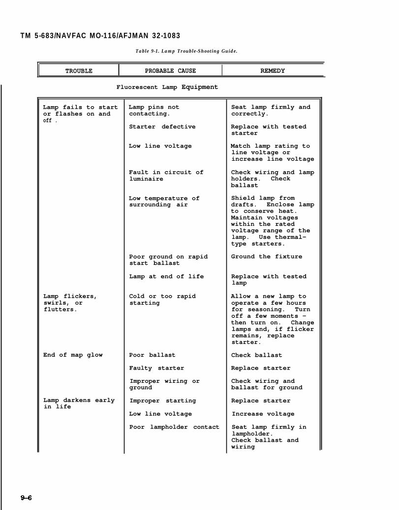
TM 5-683/NAVFAC MO-116/AFJMAN 32-1083
Table 9-1. Lamp Trouble-Shooting Guide.
I TROUBLE PROBABLE CAUSE I REMEDY
Fluorescent Lamp Equipment
Lamp fails to startor flashes on andoff .
Lamp flickers,swirls, orflutters.
End of map glow
Lamp darkens earlyin life
Lamp pins notcontacting.
Starter defective
Low line voltage
Fault in circuit ofluminaire
Low temperature ofsurrounding air
Poor ground on rapidstart ballast
Lamp at end of life
Cold or too rapidstarting
Poor ballast
Faulty starter
Improper wiring orground
Improper starting
Low line voltage
Poor lampholder contact
Seat lamp firmly andcorrectly.
Replace with testedstarter
Match lamp rating toline voltage orincrease line voltage
Check wiring and lampholders. Checkballast
Shield lamp fromdrafts. Enclose lampto conserve heat.Maintain voltageswithin the ratedvoltage range of thelamp. Use thermal-type starters.
Ground the fixture
Replace with testedlamp
Allow a new lamp tooperate a few hoursfor seasoning. Turnoff a few moments -then turn on. Changelamps and, if flickerremains, replacestarter.
Check ballast
Replace starter
Check wiring andballast for ground
Replace starter
Increase voltage
Seat lamp firmly inlampholder.Check ballast andwiring

TM 5-683/NAVFAC MO-116/AFJMAN 32-1083
Table 9-1. Lamp Trouble-Shooting Guide-Continued.
TROUBLE I PROBABLE CAUSE REMEDY
Fluorescent Lamp Equipment
Short lamp life
Radio interference
Noise from ballast
Low or high linevoltage
Lamp turned on and off
Not installed properly
Line feedback
Radiation direct fromlamp
Fluorescent equipmentis not noiseless type
Maintain branch circuitvoltage within therange specified onballasts
Frequency of startingaffects lamp life.Long periods of burninggive long life. Shortperiods of burningreduce lamp life
Auxiliary equipmentshould be enclosed in asteel channel. Wiringshould be made up withtight connection;clamps and startersshould be firmlyinstalled in socketsand fixture grounded
Install filter at radio
Locate radio antennasystem at least 10 ft.from fixtures
If unit is particularlynoisy, replaceballast
9-7
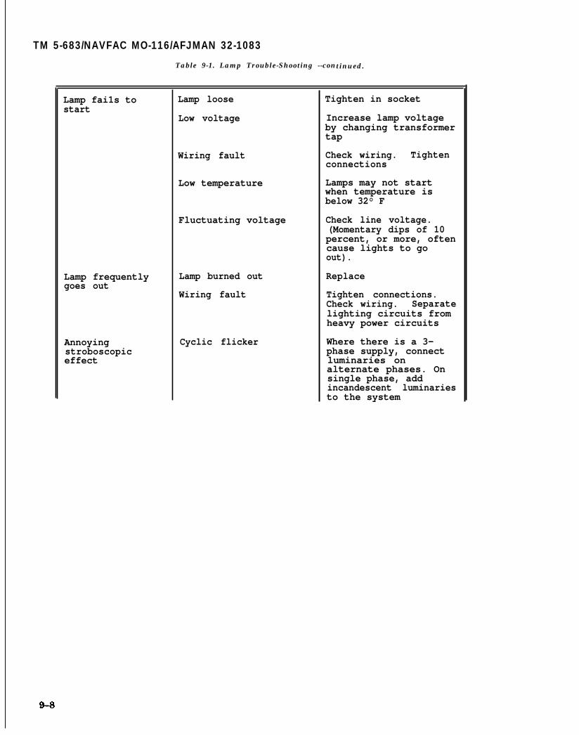
TM 5-683/NAVFAC MO-116/AFJMAN 32-1083
Table 9-1. Lamp Trouble-Shooting --continued.
Lamp fai1s tostart
Lamp frequentlygoes out
Annoyingstroboscopiceffect
Lamp loose
Low voltage
Wiring fault
Low temperature
Fluctuating voltage
Lamp burned out
Wiring fault
Cyclic flicker
Tighten in socket
Increase lamp voltageby changing transformertap
Check wiring. Tightenconnections
Lamps may not startwhen temperature isbelow 32° F
Check line voltage.(Momentary dips of 10percent, or more, oftencause lights to goout).
Replace
Tighten connections.Check wiring. Separatelighting circuits fromheavy power circuits
Where there is a 3-phase supply, connectluminaries onalternate phases. Onsingle phase, addincandescent luminariesto the system

TM 5-683/NAVFAC MO-116/AFJMAN 32-1083
Table 9-1. Lamp Trouble-Shooting Guide-Continued.
Lamp not burning Lamp loose Tighten in socket
Loose or broken Secure terminals.connections Repair wiring
Lamp burned out Replace with new lamp
Lamp burns dimly Low voltage Match lamp rating toline voltage orincrease line voltage
Short lamp life High voltage Match lamp rating toline voltage.Improve voltageregulation and avoidsurges
Lamp failure due to Replace lamp. Be suremechanical shock water does not drip on
bulb. Use roughservice lamps ifrequired
Incorrect lamp Replace with lamp ofsize for whichluminaire is rated
Excessive vibration Use vibration or roughservice lamps
Lamp breakageWater contacts bulb Use enclosed vapor-
tight luminaire ifexposed to moisture
Bulb touches luminaire Use correct lamp size
9-9

TM 5-683/NAVFAC MO-116/AFJMAN 32-1083
CHAPTER 10
BACK-UP, SECURITY, AND PROTECTION SYSTEMS
10-1. Other systems.
Previous chapters have outlined methods for servic-ing electrical system components such as switch-gear, transformers, rotating equipment, etc. Theseare the major areas in which real property electricalshops are involved. There are, however, many otherinterior systems which merit some mention. De-tailed operation and maintenance data on these sys-tems are difficult to develop due to the wide varietyof types of interior systems and the uniqueness ofeach system. It is, therefore, suggested that allmanufacturer’s publications for a particular systembe obtained and all recommended maintenance andtroubleshooting practices be followed.
10-2. Emergency and stand-by systems.
The function of an emergency power system is toprovide a source of electrical power of required ca-pacity reliability, and quality for a given length oftime to loads within a specified time after loss orfailure of the normal supply. The continued reliabil-ity and integrity of this power system is dependentupon an established program of routine mainte-nance and operational testing. This program shallbe based upon manufacturer’s recommendations,instruction books, and the minimum requirementspresented in this section. Instruction books pro-tided by the manufacturer shall contain: a detailedexplanation of the operation of the system; instruc-tions for routine maintenance; detailed instructionsfor repair of the components of the system; pictorialparts list and part numbers; and, pictorial and sche-matic electrical drawings of wiring systems, includ-ing operating and safety devices, control panels,instrumentation and annunciators.
a. Special tools and testing devices required forroutine maintenance shall be available for use whenneeded. Spare parts shall be stocked as recom-mended by the manufacturer. A written record ofinspections, tests, exercising, operation, and repairof an emergency power system shall be maintainedon the premise. This record shall include: date ofthe maintenance report; identification of the servic-ing personnel; and, notification of any unsatisfac-tory conditions and corrective actions taken, includ-ing parts replacement.
b. Transfer switches shall be subjected to amaintenance program to include tightening connec-tions, inspection or testing for evidence of overheat-ing and excessive contact erosion, removal of dust
and dirt, and replacement of contacts as required.As a minimum, a monthly load test of thirty minuteduration shall be conducted on an emergency powersystem. Backup power should be tested at full criti-cal emergency load. If it is impossible to test at fullload, then the test load capacity shall not be lessthan 50 percent of the total connected critical emer-gency load. The test should include a complete coldstart of the generator. Consideration should also begiven to more stringent conditions as recommendedby the individual energy converter manufacturer. Atthe time of emergency power system load testing,all transfer switches and emergency system circuitbreakers shall be exercised. The routine mainte-nance and operational testing program shall beoverseen by a properly instructed individual.
10-3. Signal systems.
Signal systems include nurses’ call systems, pagingsystems, buzzers, intercommunication sets andsimilar devices. For the most part, these do notrequire servicing at regular intervals. Generally, itis sufficient to clean the equipment occasionally andperform repair after some trouble is indicated. Localevaluation will be used in determining servicingrequirements.
10-4. Detection systems.
There are many types of intrusion and fire detectionsystems in use at military installations. All requirefrequent tests and checks, in some instances as of-ten as once a day. The emphasis is on operationaltests to ensure the continued functionability of thedesigned system, rather than on routine mainte-nance of component parts. Spare parts such as re-lays, contacts, batteries, transistors, pilot lampsand detectors should be stocked for fast replace-ment. Further information is available from publi-cations listed in appendix A. In all cases, the manu-facturer’s instructions should be carefulIy followed.Detection alarm systems are generally composed ofvery rugged and reliable components. Little repairwork is required other then replacement of expend-able parts and maintenance generally involves thecleaning of alarm system sensors, such as smokedetectors. Because most systems appear compli-cated and highly sophisticated at first, the tendencyis to turn over the maintenance to a service com-pany. In actuality, the systems are much less com-plicated and most electrical servicemen can masterthe work with brief training. Electrical shops nor-
10-1

TM 5-683/NAVFAC MO-116/AFJMAN 32-1083
really have all the tools and test equipment neededto service these alarm systems. Consequently, thecost will be much less if the routine maintenance isperformed in-house.
a. Fire detection system. The concept of defense indepth is applied in fire protection when an earlywarning fire detection system is used to communi-cate plant or equipment status to a central locationor assigned staff. The first line of defense is theearly warning fire detection system designed to de-tect the particles of combustion formed before overtsigns of fire appear, followed by systems designed todetect fire and release extinguishing agents. Thesystem’s purpose is to provide the earliest possiblewarning of a potential fire hazard, principally bythe extensive use of ionization smoke detections. Oneof the major advantages of using a remote multi-plexing system for fire detection is the ease of add-ing alarm detectors without the requirement of longconduit and multiple cable runs throughout theplant. A sample arrangement of this type of systemis as shown in figure 10-1. The early warning firedetection system may be a Class A proprietary pro-tective signaling system that meets the require-ments of The National Fire Protection Association(NFPA) Standard for the Installation, Maintenance,and Use of Protective Signaling Systems (NFPA 72-90). Class A and Class B fire detection circuits areshown in figure 10-2. Class A means a fire alarmcan be received and displayed at the central alarmstation in the abnormal presence of a single break of
a single ground fault in any signaling circuit. AClass B system does not include this emergencyoperating feature. NFPA 72-90 also deals with thestyles of supervisory circuits. NFPA 72-90 furtherrequires that the central alarm station be continu-ously manned. Alternative main power supplysources must be provided within the supervisorycentral station. The signal-initiating device in thefire detection system is the fire detector. The threebasic types of detectors can detect smoke, heat, andflame. In addition to these generic types, detectorscan be configure as spot type or line type (table10-1). In spop-type detectors, such as smoke detec-tors, the sensing element is concentrated at a par-ticular location. Line-type detectors sense tempera-ture changes along the length of a metal wire. Whenheat above a predetermined level reaches the linesstrung throughout an area to be protected, an alarmor alarm and fire-suppression system is triggered.Heat detectors are fixed-temperature, rate-compen-sated, or rate-of-rise types. A fixed-temperature de-tector is a device that responds when its operatingelement becomes heated to a predetermined level orhigher. A rate-compensated detector is a device thatresponds when the temperature of the air surround-ing the device reaches a predetermined level, re-gardless of the rate of temperature rise. A rate-of-rise detector is a device that responds when thetemperature rises at a rate exceeding a predeter-mined amount.

TM 5-683/NAVFAC MO-116/AFJMAN 32-1083
I A
(1) Smoke detectors. Two types of smoke detec-tors are used: ionization and photoelectric. Ioniza-tion smoke detectors contain a small amount of ra-dioactive material which ionizes the air in thesensing chamber, thus rendering it conductive andpermitting a current flow through the air betweentwo charged electrodes. When smoke particles enterthe ionization area, the detector circuit respondswith an alarm or buzzing.
(a) Photoelectric spot-type detectors containa chamber that has either overlapping or porouscovers of light that allows the entry of smoke. Theunit contains a light source and a special photosen-sitive cell in the darkened chamber. The cell is eitherplaced in the darkened chamber at an angle differ-ent from the light path or has the light blocked fromit by a light stop or shield placed between the lightsource and the cell. With the admission of smokeparticles, light strikes the particles and is scatteredand reflected into the photosensitive cell. Thiscauses the photosensing circuit to respond to thepresence of smoke particles in the smoke chamber.
(b) Flame detector is a device that respondsto the appearance of radiant energy visible to thehuman eye or to radiant energy outside the range ofhuman vision.
(c) Photoelectric flame detector is a devicewhich the sensing element is a photocell that eitherchanges its electrical conductivity or produces anelectrical potential when exposed to radiant energy.
(d) Flame flicker detector is a photoelectricflame detector with means to prevent response tovisible light unless the observed light is modulatedat a frequency characteristic of the flicker of aflame.
(e) Infrared detector is a device with a sens-ing element which is responsive to radiant energyoutside the range of human vision.
(f) Ultraviolet detector is a device with asensing element which is responsive to radiant en-ergy outside the range of human vision.
(2) Sprinkler systems. Protecting the plantfrom fire frequently requires the installation of asprinkler system. Equipment consisting of overheadpiping and attached sprinklers connected to an au-tomatic water supply protects defined spaces and avariety of hazards. There are four major types ‘ofsprinkler systems: The wet-pipe system is the sim-plest and most common. The piping is always filledwith water, which begins to flow as soon as the firstsprinkler opens. Other types are dry-pipe, deluge,and pre-action systems.
b. Security system. Before the advent of low-costcomputer multiplexed hardware, security systemswere simple hardwired alarm systems, providing aminimum level of intrusion detection. Today, thesystem may be a fully redundant computer-basedsystem interfaced with a redundant looped time-division-multiplexed communication network forgathering alarm data from sensors and for sending
10-3

TM 5-683/NAVFAC MO-116/AFJMAN 32-1083
10-4
I
I

.
commands to release locked doors under the card-access control subsystem. The remote multiplexermay be microprocessor-based units, capable of datacollection, communication with the host computer,and performing limited-access control functions.The security system provides location informationas well as delay time for the guards. By successivedetections, the security force can track the intruderand relay location information via portable radiocommunications equipment to the respondingguards. In turn, the guards can constantly informthe security force on the progress of their work orthe need for additional assistance. The cameras,using various means of target intensification, can“see” better than the human eye. Guard patrols arealso used to detect unusual activity. Perimeter de-tection is accomplished by the application of elec-tronic detection systems.
(1) Microwave detection links. These devicesare mounted on posts inside the fence. Transmittersradiate amplitude modulated X-band energy andreceivers detect and process the received energy.Thus, an invisible energy envelope is produced thatwill detect an intruder.
(2) Infrared detection links. These devices arepostlike and mounted inside the fence. Transmittersradiate multiple beams of modulated infrared en-ergy, and the receivers detect and process the en-ergy. Penetration of the invisible infrared shield willalarm the system.
(3) E-field links. Transmitter wires and re-ceiver wires are strung horizontally from mountingposts located inside the fence or mounted on thefence. A radio-frequency energy field is generatedaround the wires. The intrusion of a person into theinvisible field will “short” energy, creating an alarm.
(4) Buried sensor links. Devices sensing seis-mic, pressure, (or electromagnetic disturbances fora combination of these) are buried inside the fenceand alarm upon the intrusion of someone into thefield of detection.
(5) Other systems. Other systems are availablethat can be used in combination with the previouslymentioned systems. The probability of detection bythese outdoor devices depends on their application.Perimeter detection equipment must be appliedwith consideration of the environmental limitationsof the device’s technology. Once the intruder haspenetrated the fence, he has entered what is calledthe protected area. Once again, visual or closed-circuit television surveillance may detect the in-truder. Entry into a building is provided by theapplication of a balanced magnetic switch on doorsand openings. This device uses an internal biasmagnet to balance a delicate reed switch in the fieldof the external magnet attached to the door. Should
TM 5-683/NAVFAC MO-116/AFJMAN 32-1083
the door be opened, even a fraction of an inch, orshould another magnet be introduced in an attemptto defeat it, the switch will change state and alarm.Other devices for detection of an intruder may beapplied inside the building, including microwaveand infrared motion detection, photoelectric or laserbeams, seismic, sound detection, passive infrared,and other devices. Because all the doors are lockedand alarmed, a means of allowing personnel to en-ter and leave must be provided. Positive-access con-trol is established at the main guardhouse locatedat the perimeter fence. All persons with a need toenter the protected area are screened by explosivedetectors, metal detectors, and package X-ray detec-tion equipment. Once permitted access to the plantprotected area, they are only allowed into vital ar-eas within the plant on a need-to-enter basis. Con-trol of personnel movement into vital areas is byclosed-circuit television/electronic-access controlequipment. At each vital area door, split imageclosed-circuit television devices check the personagainst his picture identification card. He then in-serts his coded card into a magnetic reader, whichsends the coded information to the access computer.If the person has been authorized to enter the par-ticular vital area of the plant at that particulartime, the computer verifies the code and allows ac-cess. The guard watches the entrance via wide-angle closed-circuit television to ensure that theperson enters alone. Using state-of-the-art circuitdesign and multiplexing communication techniques,the alarm monitoring systems offer a high degree oftamper resistance. Redundancy is achieved by usinga central alarm station and a separately locatedsecondary alarm station. Electronic line supervisionor digitally encoded transmissions are used to pre-vent unauthorized persons from touching the sys-tem wiring. Any tampering will cause an alarm.Access control, tamper indication, and administra-tive controls combine to prevent an insider fromattempting to sabotage the plant or help an outsiderpenetrate the security system.
10-5. Monitoring systems.
Supervising the operations of the environmentalconditions throughout a building can be achieved bythe use of an integrated monitoring system. Thissystem consists of a centrally located console cap-able of continually monitoring many activities.Console input signals may be initiated by pressure,temperature, speed, humidity, air flow, electric cur-rent, water, steam, sewage, or opening or closing ofelectric contacts. With this system, an operator canquickly determine the operating condition of anynumber of sewage lift stations, air conditioningequipment, boiler auxiliaries or any other measur-
10-5

TM 5-683/NAVFAC MO-116/AFJMAN 32-1083
able condition or situation. Malfunctions are pin-pointed in moments. The necessity for making dailyfield checks is reduced or eliminated. Monitoringsystems consist of transducers located at the moni-tored equipment which convert some action into asignal which, in turn, is transmitted to the consoleby pneumatic, electrical or electronic means. De-tailed plans, instruction books and maintenancemanuals on such systems should be obtained. Build-
ing personnel, whenever possible, should survey theinstallation of the system and be able to locate com-ponents and determine operational methods. Mostmonitoring systems contain solid-state deviceswhich are very reliable, but still require annualservicing to ensure that all parts are functioningproperly (see chap 7). If skilled in-house personnelare not available, local service contracts should beused to accomplish servicing.
10-6

TM 5-683/NAVFAC
CHAPTER 11
HAZARDOUS SUBSTANCES
MO-116/AFJMAN 32-1083
11-1. Environmental protection.
This chapter concentrates on the EnvironmentProtection Agency (EPA) identification of hazard-ous substances. If a hazardous substance is re-leased into the environment in a reportable quan-tity the facility Hazardous Waste Coordinatormust be notified. “Release” by definition involvesany spilling, leaking, pumping, emitting, empty-
.ing, discharging, injecting, escaping, dumping ordisposing of a hazardous substance. A “reportablequantity’’ varies by weight for each hazardous substance. Refer to Section 311 of the Clean Water Act(CWA) for established quantities for hazardoussubstances. For hazardous substances not listed,one (1) pound or more of that substance releasedto the environment is reportable until otherwisespecified by the EPA. Failure to comply with noti-fication requirements may result in civil andcriminal penalties. In all cases, handling and dis-posing of any hazardous substance must be di-rected by the Site Hazardous Waste Coordinator.Hazardous substances include:
a. Wastes listed in the Resource Conservation andRecovery Act (RCRA).
b. Air pollutants listed in the Clean Air Act(CAA)-Section 112.
c. Substances and priority pollutants listed in theClean Water Act (CWA)-Sections 311 and 307a.
d. Chemical substances designated under theToxic Substances Control Act (TSCA)-Section 7.
e. Other substances as designated by the EPA
11-2. Polychlorinated biphenyls (PCBS).
PCBs belong to a broad family of organic chemi-cals known as chlorinated hydrocarbons. Virtuallyall PCBs have been synthetically manufactured.Their use has primarily been in transformers andcapacitors but they are also found in fluorescentballasts. PCBs are no longer intentionally manu-factured in the United States although inadver-tent production of PCB byproducts can occur whenchlorine, organic carbon, elevated temperatures orcatalysts are present together in a process. TheMonsanto Corporation was the principal domesticmanufacturer of PCBsand marketed the productunder the trade name, Aroclor. However, othercompanies who used PCBs in the manufacture oftransformers, capacitors, etc. used other tradenames (table 11-1). From an electrical standpoint,one desirable feature of PCB is its chemical stabil-
ity. Resistance to degradation by heat, oxidationetc. is very desirable. But it is the long life feature,coupled with the fact that PCB is bioaccumulativeand concentrates in the fat tissue of fish and otheranimals, including man, that has led to its identi-fication as an environmental problem. Handling,storage and disposal of PCBs and products con-taining PCBs are therefore regulated by the EPAand the Site Hazardous Waste Coordinator. Allquestions pertaining to hazardous wastes shouldbe directed to that office. Basic concepts have beenpresented to acquaint facilities personnel with thehazards of PCBs. Physical problems which mayberelated to PCB exposure include an acne-like skineruption associated with baking, soldering or heattransfer applications; changes in skin pigmentat-ion; peripheral numbness; digestive upsets; head-aches; and fatigue. PCB has also been found bythe Occupational Safety and Health Administra-tion (OSHA) to include tumors in experimentalanimals after repeated oral ingestion and con-cludes that PCBs are a potential carcinogen tohumans. Unless laboratory tests confirm the pres-ence of less than 50 parts per million (PPM) ofPCB, then all transformers or capacitors filledwith petroleum-based dielectric are assumed to bePCB-contaminated for EPA regulatory purposes.Sample testing an oil sample involves a compre-hensive test, a gas-in-oil test and a presence ofPCBstest. The gas-in-oil analysis determined theconcentrations of gases absorbed in the oil sample.The presence of PCBs analysis determines theconcentration of PCBs in the oil sample. Oil clas-sifications and concentrations are: non-PCB—lessthan 50 PPM; PCB contaminated-greater then50 PPM but less than 500 PPM and, PCB-greaterthan 500 PPM. The comprehensive test includesthe following analyses:
a. Dielectric strength.b. Color.c. Acidity.d. Water content.e. Viscosity.f. Specific gravity.g. Pour point.h. Interracial tension.i. Power factor.j. Corrosive sulphur.k. Visual examination.l. Particle count.
11-1
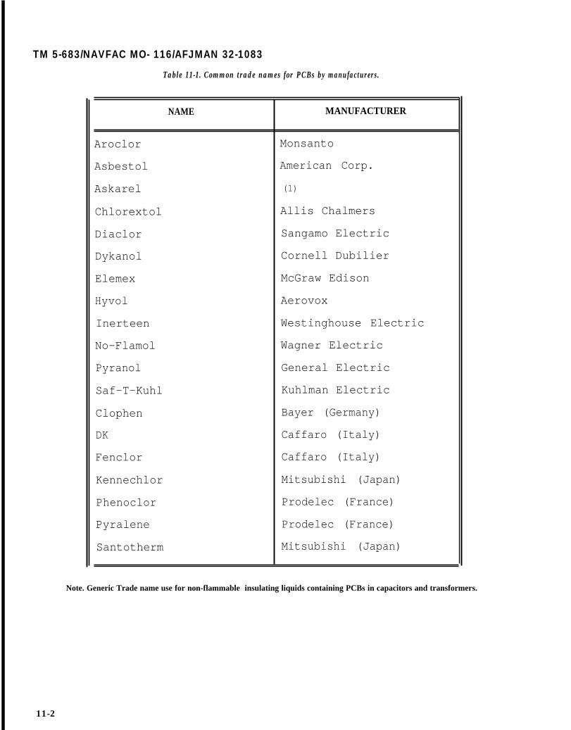
TM 5-683/NAVFAC MO- 116/AFJMAN 32-1083
Table 11-1. Common trade names for PCBs by manufacturers.
NAME MANUFACTURER
Aroclor Monsanto
Asbestol American Corp.
Askarel (1)
Chlorextol Allis Chalmers
Diaclor Sangamo Electric
Dykanol Cornell Dubilier
Elemex McGraw Edison
Hyvol Aerovox
Inerteen Westinghouse Electric
No-Flamol Wagner Electric
Pyranol General Electric
Saf-T-Kuhl Kuhlman Electric
Clophen Bayer (Germany)
DK Caffaro (Italy)
Fenclor Caffaro (Italy)
Kennechlor Mitsubishi (Japan)
Phenoclor Prodelec (France)
Pyralene Prodelec (France)
Santotherm Mitsubishi (Japan)
Note. Generic Trade name use for non-flammable insulating liquids containing PCBs in capacitors and transformers.
11-2
11-3. Lighting ballast.
Since the capacitor of the ballast in fluorescent lampscontains a small quantity of PCB the EPA has laidout regulations for the disposal of lighting ballast:
a. If the PCB lighting ballast is leaking the dis-posal is regulated under the Toxic Substance Con-trol Act (TSCA). The leaking ballast must be incin-erated at an EPA approved incinerator.
b. If the PCB lighting ballast is not leaking thedisposal is not under the TSCA. Check with yourlocal EPA office to find out any requirements in yourarea for the disposal.
11-4. Flammable liquids and gases.
Flammability is the capability of a substance toignite easily, burn intensely and spread rapidly. Ex-treme caution should be taken when storing andhandling flammable materials, follow the NationalFire Protection Association (NFPA) Standard 251.Of the flammable and combustible liquids and gasesin use, the most common are liquid hydrogen, liqui-fied petroleum gas and natural gas (methane).
a. Hydrogen. Liquid hydrogen, like other cryo-genic liquids, presents a hazard due to its extremelylow temperature, and the high pressures that canbe generated if it is allowed to evaporate in a con-fined space. However, the major hazard lies primar-ily in the wide ranges of flammability and deton-ability of gaseous hydrogen in air. The principalmethod of preventing hydrogen gas ignition or deto-nation is by diluting the gas below the lower limit offlammability and eliminating all sources of ignition.This can be accomplished by:
(1) Providing adequate ventilation.(2) Avoiding areas where pocketing may occur.(3) Minimizing confinement.(4) Limiting the amount of liquid hydrogen at
any one location.(5) Using non-sparking tools and explosion-
proof equipment.(6) Grounding equipment properly.(7) Avoiding open flames.(8) Observing no-smoking rules.
b. Liquified petroleum gas (LPG). LPG is a dan-gerous fire and explosion hazard when released inair. Vapors may flow along surfaces for substantialdistances, reach a source of ignition and flash back.LPG is also an asphyxiant. It is heavier than air,and may accumulate in pits and other low lyingareas where it may displace air. Contact with liqui-fied gas can cause frostbite. The following specialprecautions must be observed:
(1) LPG must be stored and used in wel]-ventilated areas, and kept away from heat, ignitionsources, and oxygen and chlorine cylinders.
TM 5-683/NAVFAC MO-116/AFJMAN 32-1083
(2) LPG systems shall have approved contain-ers, valves, connectors, manifold valve assembliesand regulators.
(3) LPG systems shall meet all Department ofTransportation specifications.
(4) LPG containers and vaporizers shall haveat least one approved safety relief valve.
(5) LPG shall not be stored within buildings.(6) LPG storage locations shall be equipped
with at least one 20-B/C rated fire extinguisher.c. Natural gas (methane). Under normal storage
and handling conditions, natural gas is stable whencontained. But when mixed with air or other oxidiz-ing agents, it readily becomes flammable or explo-sive. Natural gas is lighter than air and can be anasphyxiant by displacing air. The following precau-tions must be observed.
(1) Cylinders must be stored in well ventilatedand low fire hazard areas.
(2) All lines and equipment used with naturalgas must be grounded to prevent static sparks.
(3) Smoking must not be allowed. ’(4) Non-sparking tools must be used.
11-5. Toxic materials.
Toxicity is the degree to which a substance willaffect living cells under certain conditions. It is de-pendent upon the dose, rate, method and site ofabsorption. It is also dependent upon the health,tolerance, diet and temperature of an individual.Physiological effects result from inhalation, inges-tion or absorption of a toxic material. To limit thisexposure, smoking and eating are not permitted inhazardous areas, and personnel are required towash their hands thoroughly before eating, smokingor using toilet facilities.
a. Mercury. Mercury metal is a distinct hazardbecause of its property of vaporization at room tem-perature. The rate of evaporation increases withtemperature and with the surface area exposed.This property is of great importance since mercurycan seep into human skin. Mercury or metal con-taminated with mercury should never be heatedwithout providing exhaust ventilation or approvedair respirators.
b. Solvents. Special precautions should be takenwhen working with solvents due to potential toxicaffects and flammability characteristics. Protectivemeasures include providing plenty of ventilation orrespirators; using rubber gloves, chemical safetygoggles, and face shields; and providing for immediateavailability of emergency eyewash facilities. Trichlor-ethylene and perchloroethylene are solvents sus-pected of being carcinogenic. The use of carbon tetra-chloride as a solvent is prohibited. Acute poisoningcaused by prolonged inhalation may result in death.
11-3
TM 5-683/NAVFAC MO-116/AFJMAN 32-1083
CHAPTER 12
ELECTRICAL SAFETY
12-1. Human factor.
The protection of human life is paramount. Electri-cal equipment can be replaced; lost production canbe made up; but human life can never be recoverednor human suffering ever compensated. The princ-ipal personnel dangers from electricity are that ofshock, electrocution, and/or severe burn from anelectrical arc or its effects, which may be similar tothat of an explosion. The major contributors towork-related electrical accidents are unsafe condi-tions or unsafe practices. The most common unsafeconditions are damaged, defective, burned or wetinsulation or other parts; improperly guarded orshielded live parts; loose connections or strandspulled loose; and equipment not grounded, or pooror inadequate grounding connection. Unsafe prac-tices include failing to de-energize equipment beingrepaired or inspected; assuming an unsafe positionnear energized equipment; using tools or equipmenttoo near bare energized parts; and misusing tools orequipment. Safety manuals provided by the mili-tary services are based upon the National ElectricalSafety Code (NESC) which establishes general safepractices for construction, maintenance, and opera-tion of all electric utility systems. The rules con-tained in these manuals are considered mandatoryand must therefore be referenced at all times. Anydeviations from these procedures must be agreedupon by the safety director. In general, to improvesafety to personnel and avoid accidents, special at-tention must be directed to the following:
a. Be alert. Alertness is particularly essential onnew assignments until safe habits are formed, butshould never be relaxed since conditions oftenchange.
b. Be cautious. Caution should be exercised at alltimes.
c. Develop safe habits. Safe habits result fromrepeated alertness and caution, and continuous ad-herence to the rules.
d. Know your job. Have complete and thoroughinformation before proceeding.
e. Observe the rules. The rules and instructionsapplying to a variety of cases, both electrical and “mechanical in nature, cover most of the commoncauses of accidents.
12-2. Equipment isolation.
As a general rule, no electrical apparatus should beworked on while it is energized. If it is not known
whether a circuit is de-energized or not, it must beassumed that the circuit is energized and dangerousuntil such time it is proven otherwise. It is alsoimportant to regard exposed copper as energizedand treat it accordingly since copper is rarely usedexcept to carry current. When working near electric-ity, do not use metal rules or flashlights, or metallicpencils, and do not wear watch chains, finger ringsor other objects having exposed conducting mate-rial.
a. De-energization. Personnel, who must work onde-energized equipment, should be protectedagainst shock hazard and flash burns that couldoccur if the circuit were inadvertently re-energized.To provide this protection, the circuit must first bede-energized. Check applicable up-to-date draw-ings, diagrams and identification tags to determineall possible sources of supply to the specific equip-ment. Open the proper switches and/or circuitbreakers for each source in order to isolate theequipment to be worked on. In cases where visibleblade disconnecting devices are used, verify that allblades are fully open. Drawout-type circuit breakersshould be withdrawn to the fully disconnected posi-tion. Do not consider automatic switches or controldevices to be a disconnecting means for personnelsafety.
b. Tagging and lock-out. All employees shouldplan for safety by following all lockout procedurerules before beginning work on any equipment.Four steps vital to any good lockout procedure are:
(1) Lock the equipment to prevent its use. Anyenergized equipment should be shut down by turn-ing off power or closing valves to eliminate the pos-sibility of electrocution, the inadvertent operation ofmachinery, or the release of hazardous materials.
(2) Identify the equipment to let other employ-ees know it is not in service, when the lockout wasinitiated, and the purpose of the lockout.
(3) Clear the area to assure that other employ-ees are a safe distance from the equipment beforethe lockout is tested.
(4) Test the equipment to verify that the equip-ment cannot be energized and that the lockout ren-ders it inoperable. Before the test, check to be surethat all interlocks are engaged.
(5) Once the equipment is isolated, precautionsmust be taken to guard against accidental re-energization. Attach to the operating handles of theopen disconnecting devices padlocks (fig 12-1)and/or approved red safety tags (fig 12-2). Red tags
12-1

TM 5-683/NAVFAC MO-116/AFJMAN 32-1083
Figure 12-1. Padlock and multiple lock adapter.
DONOTOPERATE
Figure 12-2. Typical safety tag.
are applied to devices to ensure that their positionswill not be changed by unauthorized persons as longas equipment is blinked out and red tagged. Thesetags must identify the person having the key to thelock and the reason why the circuit is open. Theymust also show the time and date of its application.If fuses have been removed to de-energize the equip-ment, special precautions should be taken to pre-vent their unauthorized reinsertion. The followinggeneral rules should be observed in every lockoutsituation:
(a) An employee should never give a lock toanother employee.
(b) Maintenance personnel should learnproper lockout procedures.
12-2
(c) All employees must follow correct lockoutprocedures.
c. Testing for voltage. After the equipment hasbeen de-energized, tagged and locked out, the cir-cuit must be tested to confirm that all conductors tothe equipment are de-energized. This test is espe-cially important on circuits which involve switchesand freed-type breakers in which the blades cannotbe visually checked. Use a volt meter or a volt-ohm-milliammeter (VOM) as described in paragraph13-2 to test the de-energized circuit for zero volts.Before and after testing the affected conductors,determine that the VOM is operating satisfactorilyby testing the voltage of a source which is known tobe energized. Once these steps are completed, theequipment is safe to work on.
d. Maintenance grounding. In spite of all precau-tions, de-energized circuits can be re-energized inad-vertently. When this occurs, adequate maintenanceor safety grounding is the only protection for person-nel. For this reason, it is especially important thatadequate grounding procedures be established andrigidlv enforced. The tools used to apply a mainte-nance ground are primarily special heavy-dutyclamps which are connected to cables of adequatecapacity. These clamps and cable should not be largerthan necessary because bulkiness and weight hinderpersonnel while connecting them to the conductors,Chains, small diameter wire or battery clampsshould not be used to apply a maintenance groundbecause they can easily be vaporized in the event of afault. Prior to application, ground cables should beinspected for broken strands in the conductors andloose connections to the clamp terminals, and clampmechanisms should be checked for defects. Defectiveequipment should be replaced. Maintenance groundsshould be applied on each side of a work point, or ateach end of a de-energized circuit.

(1) Ground cables. Ground cables must be sizedfor the maximum available fault current. Due to thewide range of system voltages and fault currents, nopublished standards have been developed for spe-cific applications or locations of grounding cables. Ageneral survey of commercially available groundingand related safety devices shows use of 1/0 Ameri-can Wire Gauge (AWG) copper cables. This size ap-pears to be a good compromise between a reason-able range of fault currents, the cable’s ability tosafely conduct those currents given the thermal ca-pacity, and the ease of physically handling the par-ticular size wire. Ground cables (fig 12-3) should beno longer than necessary in order to keep cableresistance as low as possible and to minimize cableslack thereby preventing their violent movementunder fault conditions. Ground cables should beconnected first to the metal structure or switchgearground bus and then to a phase conductor of thede-energized equipment. Then the ground cablesshould be connected between phases and to the sys-tem neutral (when available) to minimize the volt-age drop across the work area should re-energization occur. When removing maintenancegrounds, the above procedure should be reversed.
TM 5-683/NAVFAC MO-116/AFJMAN 32-1083
Care must be taken to remove all ground cablesbefore the equipment is m-energized. It is recom-mended that all conductors be tested with amegohmmeter to ascertain if any are still grounded.
(2) Ground clamps. Solid metal-to-metal con-nections are essential between ground clamps (fig12-4) and the de-energized equipment. Groundclamps should have serrated jaws because it is im-practical to clean conductors from paint or corro-sion. The clamps should be tightened slightly inplace, given a rotation on the conductors to providea cleaning action by the serrated jaws, and then besecurely tightened. Ground clamps which attach toswitchgear ground bus are equipped with pointed orcupped set screws which should be tightened toensure penetration through corrosion and paint, toprovide adequate connections.
12-3. Switchgear.
The following precautions should be taken whenworking on switchgear.
a. Before you work on the switchgear enclosure,remove all drawout devices, such as circuit break-ers, instrument transformers, fuses and controlpower transformers.
Figure 12-3. Ground cable.
12-3

TM 5-683/NAVFAC MO-116/AFJMAN 32-1083
TOWER
Figure 12-4. Grounding clamps.
b. Do not lay tools on the equipment while youare working. It is too easy to forget a tool whenclosing an enclosure.
c. Circuit breakers and switches are rated atmaximum capacity and must not be used beyondthis limit for fear of exploding an under-rated de-vice.
d. If the enclosure is to be opened for any work atall, make sure power is off the bus. The insulatingcoating on the buswork is not sufficient to protectpersonnel working around it.
e. Knife switches must not be used to open powercircuits, except for certain approved types of en-closed switches designed for that purpose. Beforeclosing a disconnecting switch, make sure that con-ditions are safe for such an operation. Then throwthe switch with a swift action without hesitation.Keep the body away from the front of these enclo-sures when operating them. Turn your head to pre-vent being burned from a possible flash.
f. Maintenance closing devices for switchgear arenot suitable for closing in on an energized system.
12-4. Capacitors.
Before changing capacitor connections or doingwork of any kind on them, discharge the capacitorswith a properly insulated medium from terminal toterminal, terminals to case, and case to ground.Remember to keep capacitors short-circuited whennot in use.
12-4
CABLE
12-5. Rotating equipment.
The safety tips below must being on rotating equipment:
followed when work-
a. All rotating machinery must be carefully andthoroughly inspected for foreign objects before beingstarted. This inspection must cover the machineboth inside and outside. Loose articles lying on thebase, pedestals, frame or blocking may fall or bedrawn into the rotating parts; articles inside themachine may be thrown out.
b. Do not wear neckties or any other loose cloth-ing, or carry loose tools that may get caught inrotating machinery.
c. At all times, the frames of all machinery, in-cluding portable hand tools, must be securelygrounded.
d. While a machine is in motion or has voltageapplied, brushes shall not be shifted. Even wheninspecting brushes, the voltage should not be re-moved and extreme caution must be observed.
e. The commutators of DC machines must not becleaned while voltage is applied. If cleaning is nec-essary, disconnect the source of power and allow themachine to coast while the operation is being per-formed.
f. Never open a field circuit unless some meansis available to limit the induced voltage. Cutting ina discharge resistance is effective and protects anoperator from injury and the machine from damage.
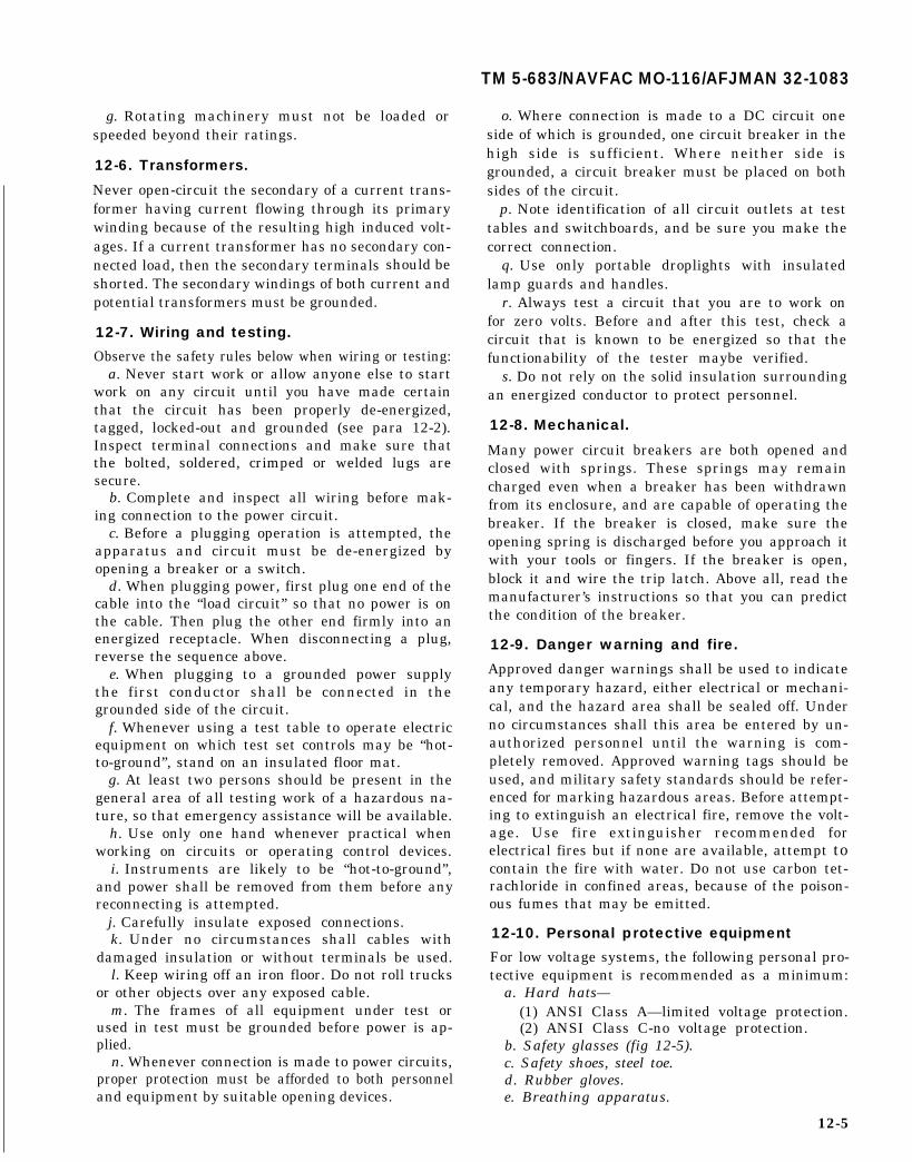
TM 5-683/NAVFAC MO-116/AFJMAN 32-1083
g. Rotating machinery must not be loaded orspeeded beyond their ratings.
12-6. Transformers.
Never open-circuit the secondary of a current trans-former having current flowing through its primarywinding because of the resulting high induced volt-ages. If a current transformer has no secondary con-nected load, then the secondary terminals should beshorted. The secondary windings of both current andpotential transformers must be grounded.
12-7. Wiring and testing.
Observe the safety rules below when wiring or testing:a. Never start work or allow anyone else to start
work on any circuit until you have made certainthat the circuit has been properly de-energized,tagged, locked-out and grounded (see para 12-2).Inspect terminal connections and make sure thatthe bolted, soldered, crimped or welded lugs aresecure.
b. Complete and inspect all wiring before mak-ing connection to the power circuit.
c. Before a plugging operation is attempted, theapparatus and circuit must be de-energized byopening a breaker or a switch.
d. When plugging power, first plug one end of thecable into the “load circuit” so that no power is onthe cable. Then plug the other end firmly into anenergized receptacle. When disconnecting a plug,reverse the sequence above.
e. When plugging to a grounded power supplythe first conductor shall be connected in thegrounded side of the circuit.
f. Whenever using a test table to operate electricequipment on which test set controls may be “hot-to-ground”, stand on an insulated floor mat.
g. At least two persons should be present in thegeneral area of all testing work of a hazardous na-ture, so that emergency assistance will be available.
h. Use only one hand whenever practical whenworking on circuits or operating control devices.
i. Instruments are likely to be “hot-to-ground”,and power shall be removed from them before anyreconnecting is attempted.
j. Carefully insulate exposed connections.k. Under no circumstances shall cables with
damaged insulation or without terminals be used.l. Keep wiring off an iron floor. Do not roll trucks
or other objects over any exposed cable.m. The frames of all equipment under test or
used in test must be grounded before power is ap-plied.
n. Whenever connection is made to power circuits,proper protection must be afforded to both personneland equipment by suitable opening devices.
o. Where connection is made to a DC circuit oneside of which is grounded, one circuit breaker in thehigh side is sufficient. Where neither side isgrounded, a circuit breaker must be placed on bothsides of the circuit.
p. Note identification of all circuit outlets at testtables and switchboards, and be sure you make thecorrect connection.
q. Use only portable droplights with insulatedlamp guards and handles.
r. Always test a circuit that you are to work onfor zero volts. Before and after this test, check acircuit that is known to be energized so that thefunctionability of the tester maybe verified.
s. Do not rely on the solid insulation surroundingan energized conductor to protect personnel.
12-8. Mechanical.
Many power circuit breakers are both opened andclosed with springs. These springs may remaincharged even when a breaker has been withdrawnfrom its enclosure, and are capable of operating thebreaker. If the breaker is closed, make sure theopening spring is discharged before you approach itwith your tools or fingers. If the breaker is open,block it and wire the trip latch. Above all, read themanufacturer’s instructions so that you can predictthe condition of the breaker.
12-9. Danger warning and fire.
Approved danger warnings shall be used to indicateany temporary hazard, either electrical or mechani-cal, and the hazard area shall be sealed off. Underno circumstances shall this area be entered by un-authorized personnel until the warning is com-pletely removed. Approved warning tags should beused, and military safety standards should be refer-enced for marking hazardous areas. Before attempt-ing to extinguish an electrical fire, remove the volt-age. Use fire extinguisher recommended forelectrical fires but if none are available, attempt tocontain the fire with water. Do not use carbon tet-rachloride in confined areas, because of the poison-ous fumes that may be emitted.
12-10. Personal protective equipment
For low voltage systems, the following personal pro-tective equipment is recommended as a minimum:
a. Hard hats—(1) ANSI Class A—limited voltage protection.(2) ANSI Class C-no voltage protection.
b. Safety glasses (fig 12-5).c. Safety shoes, steel toe.d. Rubber gloves.e. Breathing apparatus.
12-5
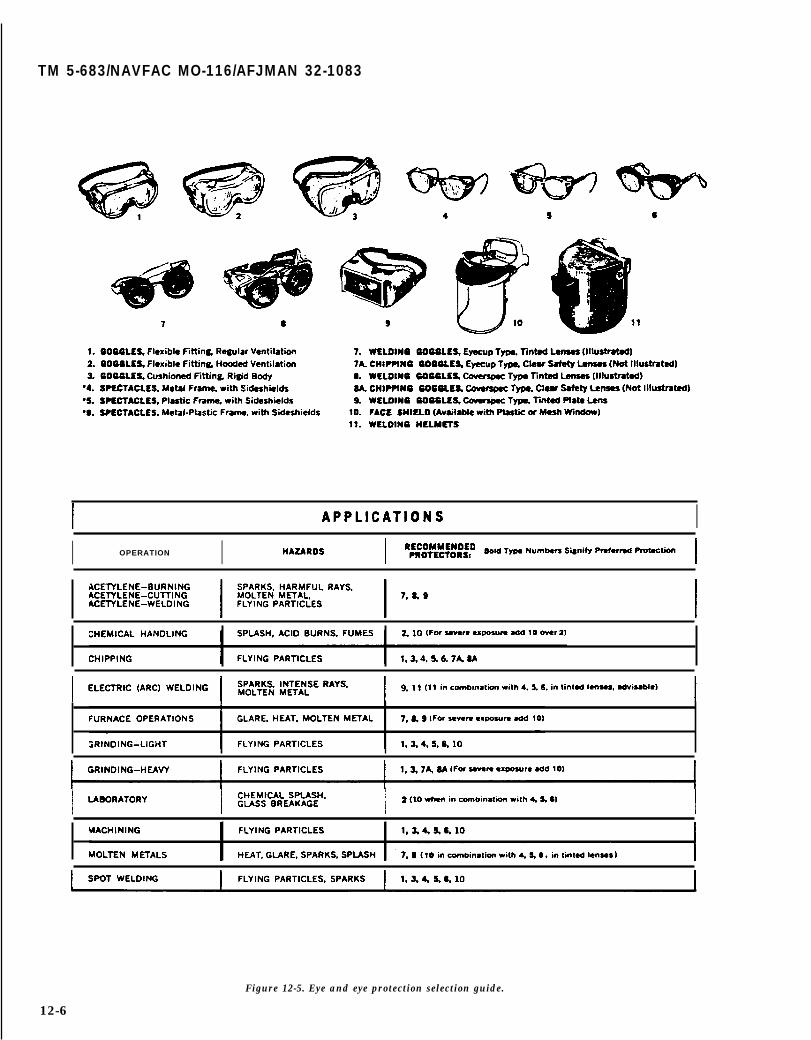
TM 5-683/NAVFAC MO-116/AFJMAN 32-1083
I II OPERATION I
Figure 12-5. Eye and eye protection selection guide.
12-6
TM 5-683/NAVFAC MO-116/AFJMAN 32-1083
CHAPTER 13
TEST EQUIPMENT
13-1. Equipment maintenance.
Accurate and appropriate test equipment is criticalto the maintenance of electrical equipment. Listedin table 13-1 are some of the tools and equipmentthat each military facility electrical shop shouldpossess. A brief description of the equipment appli-cation is also given. To perform specialized testing,such as infrared or insulation resistance testing,special equipment may be rented, or purchased de-pending upon projected future use. This testing maybe performed by experienced military facilities per-sonnel, or it may be contracted to an electrical test-ing shop. In the sections that follow three of themore common and versatile test equipment avail-able are described: the volt-ohm-miniammeter, theclamp-on volt-ammeter, and the megohmmeter. Asin the use of all test equipment, these devicesshould be used in strict compliance with the manu-facturer’s instructions and recommendations. Fail-ure to do so may result in injury to personnel mak-ing the tests as well as produce meaningless data.
13-2. Volt-ohm-milliammeter (VOM).
This meter incorporates the functions of the voltme-ter, ohmmeter and milliammeter into one instru-ment. A VOM can be used to measure AC or DCvoltage, current and resistance, with several rangesfor each function. There are also solid-state VOMSwhich perform the same functions. For precise oper-ating procedures, the manufacturer’s instructionsmust be referenced. A VOM which measures trueRMS should be used.
a. Safety precautions. A VOM is usually designedto prevent accidental shock to the operator whenproperly used. However, careless use of the instru-ment can result in a serious or fatal accident. TheVOM should only be used by personnel qualified torecognize shock hazards and trained in the safetyprecautions required to avoid possible injury. Safetyprecautions are as follows:
(1) Do not work alone when making measure-ments of circuits where a shock hazard can exist.Notify another person that you are, or intend tomake such measurements.
(2) Locate all voltage sources and accessiblepaths prior to making measurement connections.Check that the equipment is properly grounded andthe right rating and type of fuse(s) are installed. Setthe instrument to the proper range before power isapplied.
(3) Remember, voltages may appear unexpect-edly in defective equipment. An open bleeder resis-tor may result in a capacitor retaining a dangerouscharge. Turn off power and discharge all capacitorsbefore connecting or disconnecting test leads to andfrom the circuit being measured.
(4) For your own safety, inspect the test leadsfor cracks, breaks or flaws in the insulation, prodsand connectors before each use. If any defects exist,replace the test leads immediately.
(5) Do not make measurements in a circuitwhere corona is present. Corona can be identified byits sound, the odor of ozone or a pale-blue coloremanation from sharp metal points in the circuit.
(6) Hands, shoes, floor and workbench must bedry. Avoid making measurements under humid,damp, or other environmental conditions that couldaffect the dielectric withstanding voltage of the testleads or instrument.
(7) For maximum safety, do not touch testleads or instrument while power is applied to thecircuit being measured.
(8) Use extreme caution when making mea-surements in a radio frequency (RF) circuit where adangerous combination of voltage could be present,such as in a modulated RF amplifier.
(9) DO not make measurements using testleads which differ from those originally furnishedwith the instrument.
(10) Do not come into contact with any objectwhich could provide a current path to the commonside of the circuit under test or power line ground.Always stand on a dry insulating surface capable ofwithstanding the voltage being measured, or thatcould be encountered.
(11) The range or function switch should onlybe changed when the power to the circuit undermeasurement is turned off. This will provide maxi-mum safety to the user, eliminate arcing at theswitch contacts and prolong the life of the meter.
b. Operation. Before making any measurements,the VOM pointer must be adjusted to zero. With theVOM in operating position, check that the pointerindicates zero at the left side of the scale when thereis no input. If pointer is off zero, adjust the screwlocated in the case below center of the dial. Use asmall screwdriver to turn the screw slowly clock-wise or counterclockwise until the pointer is exactlyover the zero mark at the left side of the scale. Withthe indicating pointer set on the zero mark, reversethe direction of rotation of the zero adjuster. Rotate
13-1

TM 5-683/NAVFAC MO-116/AFJMAN 32-1083
Table 13-1. Tools and equipment for effective electrical maintenance.
TOOLS OR EQUIPMENT

TM 5-6831/NAVFAC MO-116/AFJMAN 32-1083
Table 13-1. Tools and equipment for effective electrical maintenance--continued.
the zero adjuster a sufficient amount to introducemechanical-freedom or “play’’ but insufficient or dis-turb the position of the indicating pointer. This pro-cedure will eliminate disturbances to the zero set-ting from subsequent changes in temperature,humidity, vibration and other environmental condi-tions. Once the VOM is zero adjusted, anyone ofadozen measurements canbe made. The two morecommon tests are for AC voltage and resistance.
(l) AC voltage measurement. Outlined below isthe procedure for measuring voltage in a circuit. Becareful when measuring line voltage, be sure that therange switch is set to the proper voltage position.
(a) Set the function switch at AC (fig 13-1).(b) Set the range switch at the desired voltage
range position. When in doubt as to the actual volt-age present, always use the highes tvoltage range asa protection to the instrument. If the voltage iswithin a lower range, the switch maybe set for thelower range to obtain a more accurate reading.
(c) Plug a test lead in the– COMMON jackand another test lead in the + jack.
(d) Connect the test leads across the voltagesource.
(e) Turn on power in the circuit being mea-sured.
(f) Read the value on the scale.(2) Resistance measurement. The procedure for
measuring resistance is outlined below.(a) Prior to measuring a resistance, the VOM
must be adjusted to zero. Turn range switch to de-
sire ohms range (fig 13-2). Plug a test lead in the –COMMON jack and another test lead in the + jack.Connect ends of test leads to short the VOM resis-tance circuit. Rotate the ZERO OHMS control untilpointer indicates zero ohms. If pointer cannot beadjusted to zero, one or both the VOM internalbatteries must be replaced. Before measuring resis-tance be sure power is off to the circuit being tested.Disconnect the component from the circuit beforemeasuring its resistance.
(b) Set the range switch to one of the resis-tance range Positions.
(c) Set the function switch at either – DC or+ DC. Operation is the same in either position.Adjust ZERO OHMS control for each resistancerange as described in (a).
(d) Observe the reading on the OHMS scaleat the top of the dial. Note that the OHMS scalereads from right to left for increasing values of re-sistance.
(e) To determine the actual resistance value,multiply the reading by the factor at the switchposition.
(f) If there is a “forward” and “backward” re-sistance such as in diodes, the resistance should berelatively low in one direction (for forward polarity)and higher in the opposite direction. Rotate thefunction switch between the two DC positions toreverse polarity. This will determine if there is adifference between the resistance in the two direc-tions.
13-3

TM 5-683/NAVFAC MO-116/AFJMAN 32-1083
ZEROADJUST
FUNCTIONSWITCH
n I
AC VOLTS—METERIN PARALLEL
Figure 13-1. Set-up for measuring AC voltage.
13-3. Clamp-on volt-ammeter.Most clamp-on volt-ammeters are designed to readalternating current only, although some types areavailable which will read direct current as well.Most are provided with plug-in leads so that theinstruments can be used as voltmeters. Some mod-els can also be used as ohmmeters. Refer to themanufacturer’s instructions for operational proce-dures.
a. Application. Where a conductor is accessible at600 volts or below, clamp-on volt-ammeters are usedsimply by clamping the instrument around insu-lated or noninsulated conductors. Thus with no in-
terruption of service, the user may check motorloads and starting current for fractional-horsepowermotors. Other applications include balancingpolyphase systems, locating overloaded feeders,checking line voltages, trouble shooting fuse boxesand control circuits, repairing electrical appliances,and diagnosing miscellaneous operating problems.Although the clamp-on volt-ammeter is easy to use,care must be taken to obtain accurate readings. Forexample, be sure that the frequency of the circuitunder test is within the range of the instrument.Many of these instruments are calibrated at 60Hertz. Also, take care that stray magnetic fields do
13-4

TM 5-683/NAVFAC MO-116/AFJMAN 32-1083
FUNCTIONSWITCH
I
Figure 13-2. Set-up for measuring resistance.
not affect the current reading. When taking currentreadings, try to arrange conductors so that they areas far removed as possible from the conductor-undertest. If testing is being done in a control panel, try totake the current readings at a location remote fromrelay magnet coils which could influence the accu-racy of the reading. Also, avoid taking current read-ings on conductors at a point close to a transformer.Where a conductor is inaccessible at 600 volts orbelow, for instance in conduit or cable troughs, cur-rent can still be measured by using a currentadapter in the fused disconnect switch. Thecartridge-fuse type has three sets of adapters for
various fuse sizes. The blade-fuse type is screwedonto the fuse holder in the switch box. The clamp-onammeter function should not be used on pulsatingdc because it will give erroneous readings.
b. Accessories. A clamp-on range extender per-mits the measurement of high currents beyond therange of the clamp-on volt-ammeter. The unit ex-tends the current range ten times and allows anactual current reading of 1000 amps AC on the0-100A meter scale. A current multiplier permitscurrent measurement on low-current equipment.The device multiplies the load current by lx, 5x or10x. A phase sequence indicating attachment is
13-5

TM 5-683/NAVFAC MO-116/AFJMAN 32-1083
used in conjunction with the voltmeter circuit of theclamp-on volt-ammeter. To determine phase se-quence, the circuit voltage is first measured. Thenconnections are made as shown in figure 13-3. If themeter reading is higher than the original circuitvoltage, the phase sequence is black-yellow-red. Ifthe meter reading is below original circuit voltagethe phase sequence is red-yellow-black.
13-4. Megohmmeter.
The megohmmeter is an instrument used to meas-ure very high resistances (fig 13-4). The meggerconsists of a hand-driven direct-current generatorand a meter to indicate resistance in ohms. Themeter used is an opposed coil type, having two coils,A and B, mounted over a gapped core (fig 13-5). Thecoils are wound on a light frame, and rotate aroundthe core which remains stationary. The current forthe coils is supplied by the hand-driven generator.To explain the operation of the unit, it is necessaryto examine the action of the coils with the earth andlien terminals open; with these terminals shorted;and with a resistance (Rx) across these terminals.When these terminals are open, current flow is fromthe generator, through B and R which are in serieswith the generator. Since the terminals are open, nocurrent flows through coil A to oppose movementand coil B will swing counterclockwise to a positionover the gap in the core. In this position the pointerindicates infinity. With the terminals shorted to-gether, a larger current flows through coil A thanthrough coil B and the greater force in coil A movesthe pointer clockwise to the zero position on thescale. Resistor R’ is a current limiting resistor
which prevents damage to the meter in this situa-tion. If a resistance is connected across the termi-nals, current flows through coil A, R' and the un-known resistance Rx. This current attempts tomove coil A clockwise, but the opposing force createdby current through coil B tries to move it counter-clockwise. The final position of the coils is deter-mined by the magnitude of the current through Rx’and the coils will stop at a point where the forcestending to move them are at a balance. The pointerthen indicates the value of the unknown resistanceon the scale. No springs are used in the movementsince the opposing forces in coils A and B balancethe pointer when a reading is being taken. Havingno springs to hinder its movement, the pointerfloats freely back and forth across the scale whenthe meter is not in operation. Megohmmeters maybe obtained with different voltage ranges; the morecommon being 500 and 1000 volts. The higher theresistance range to be measured, the higher thevoltage required to actuate the movement for read-ing. Friction clutches are used to hold the generatorto its rated voltage output. In operation, theseclutches are designed to slip if cranked over a cer-tain rate of speed, thus dropping the output to asafe value.
a. Safety precautions. When operating amegohmmeter, a very high voltage is generated atthe output terminals which could prove fatal. Thefollowing safety precautions should be adhered towhen operating a megohmmeter.
(1) Take the equipment to be tested out of ser-vice. This involves de-energizing the equipment anddisconnecting it from other equipment and circuits.
BLACK
PHASE SEQUENCE ADAPTER
- VOLTAGE LEADS
3 PHASE LINE
Figure 13-3. Setup for testing phase sequence.
13-6
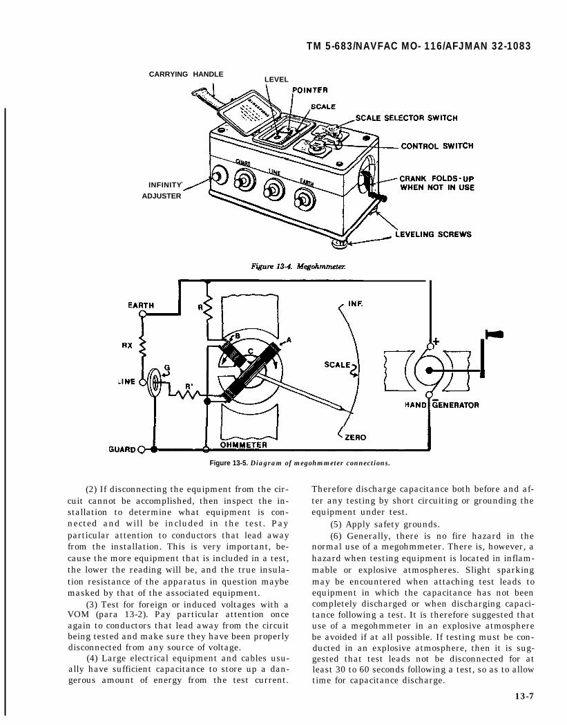
TM 5-683/NAVFAC MO- 116/AFJMAN 32-1083
CARRYING HANDLELEVEL
INFINITY
ADJUSTER
Figure 13-5. Diagram of megohmmeter connections.
(2) If disconnecting the equipment from the cir-cuit cannot be accomplished, then inspect the in-stallation to determine what equipment is con-nected and will be included in the test. Payparticular attention to conductors that lead awayfrom the installation. This is very important, be-cause the more equipment that is included in a test,the lower the reading will be, and the true insula-tion resistance of the apparatus in question maybemasked by that of the associated equipment.
(3) Test for foreign or induced voltages with aVOM (para 13-2). Pay particular attention onceagain to conductors that lead away from the circuitbeing tested and make sure they have been properlydisconnected from any source of voltage.
(4) Large electrical equipment and cables usu-ally have sufficient capacitance to store up a dan-gerous amount of energy from the test current.
Therefore discharge capacitance both before and af-ter any testing by short circuiting or grounding theequipment under test.
(5) Apply safety grounds.(6) Generally, there is no fire hazard in the
normal use of a megohmmeter. There is, however, ahazard when testing equipment is located in inflam-mable or explosive atmospheres. Slight sparkingmay be encountered when attaching test leads toequipment in which the capacitance has not beencompletely discharged or when discharging capaci-tance following a test. It is therefore suggested thatuse of a megohmmeter in an explosive atmospherebe avoided if at all possible. If testing must be con-ducted in an explosive atmosphere, then it is sug-gested that test leads not be disconnected for atleast 30 to 60 seconds following a test, so as to allowtime for capacitance discharge.
13-7

TM 5-683/NAVFAC MO-116/AFJMAN 32-1083
(7) Do not use a megohmmeter whose terminaloperating voltage exceeds that which is safe to ap-ply to the equipment under test.
b. Operation. The following are general directionsfor operating a hand-driven megohmmeter. For spe-cific instructions, refer to the megohmmeter manu-facturer’s instructions. For megohmmeter connec-tions when testing low voltage cables or motors,refer to paragraphs 6-3 and 4-5, respectively.
(1) Place the megohmmeter on a firm and levelbase. Avoid large masses of iron and strong mag-netic fields.
(2) If the megohmmeter has a selector switch,set it to MEGOHMS + 1.
(3) Check infinity by turning the hand crank ina clockwise direction. The pointer should movepromptly to infinity. This check is made with noconnections to the test terminals. If the reading isnot infinity, then use the INFINITY ADJUSTER toset the pointer to infinity.
(4) Check zero by short-circuiting the testingterminals. Turn the crank slowly. The pointershould move promptly to zero or off the lower end ofthe scale.
(5) Use well-insulated testing leads connectedto the megohmmeter terminals and with oppositeends separated, turn the crank. If the pointer indi-cates less than infinity, there is a leak between theleads which must be removed before proceedingwith tests. Touch together the test ends of the leadswhile turning the crank to make certain, by a zeroreading, that the leads are not open-circuited.
(6) Apparatus to be tested must not be live. Itmust be taken out of service and disconnected elec-trically from all other equipment (para 13-4.1).
(7) Connect leads to apparatus to be tested. Fortesting to ground, connect from the LINE terminalto a conductor of the apparatus, and from theEARTH terminal to the frame of a machine, thesheath of a cable or to a good ground. For testingbetween two conductors, connect test leads to thetwo conductors.
(8) Turn the crank in the clockwise directionand observe the position of the pointer over thescale. It shows the value of the insulation resistanceunder test. Take the reading while operating and ata fixed time, preferably 30 or 60 seconds.
13-5. Harmonic measurements.
The increasing use of solid-state switching devicescontributes to current wave forms which arenonsinusoidal. This distorted current wave form re-sults in a distorted voltage waveform. This distortedwave form can be viewed as a fundamental 60 Hzsine wave with odd multiples of 60 Hz harmonicswave forms. Even harmonics are usually n o t
13-8
present in an AC system, except under special cir-cumstances. The common frequency range of har-monics is O-5 kHz with O-3 Khz being most common.If the harmonic levels are high, they may cause:interference to control and communication lines;heating of ac motors, transformers and conductors;higher reactive power demand and hence poorpower factor; misoperation of sensitive electronics;overloading of shunt capacitors and, higher powerloss. These harmonic currents will accumulate inthe neutral conductor. Therefore, it is recommendedthat a double ampacity neutral conductor be used.
a. The purpose of harmonic measurements is:(1) Monitoring existing values of harmonics
and checking against recommended or admissiblelevels.
(2) Testing equipment which generates har-monics.
(3) Diagnosis and trouble-shooting situationswhere the equipment performance is unacceptableto the utility or to the user.
(4) Observations of existing background levelsand tracking the trends in time of voltage and cur-rent harmonics (daily, monthly, seasonal patterns).
b. Basic equipment used for the measurement ofnonsinusoidal voltage and currents. The techniquesused for harmonics measurements differ from ordi-nary power system measurement. The harmonicmeasurements require more specialized instru-ments. Brief descriptions for three generic types ofinstruments used for harmonic measurements areincluded in this section.
(1) Oscilloscope. The display of the voltagewave-form on the oscilloscope gives immediatequalitative information on the degree and type ofdistortion. Sometimes cases of resonances arereadily identifiable through the multiple peakspresent in the current wave.
(2) Spectrum analyzers. These instruments dis-play the signal as a function of frequency. A certainrange of frequencies is scanned and all the compo-nents, harmonics and interharmonics of the ana-lyzed signal are displayed. The display format maybe a CRT or a chart recorder. For harmonic mea-surements, the harmonic frequencies must be iden-tified by reference to the fundamental frequency. Awide range of analog and digital types of SpectrumAnalyzers are available in the market.
(3) Wave analyzers. Harmonic analyzers orwave analyzers measure the amplitude (and alsophase angle in more complex units) of a periodicfunction. These instruments provide the line spec-trum of an observed signal. The cutput can be re-corded or can be monitored with analogue or digitalmeters. An example of these is the Dranetz 636disturbance wave analyzer. Again instruments with

a wide range of capabilities are available startingfrom printing results on a paper tape to automaticstoring on a personal computer. Also several differ-ent manufacturers have similar instruments.
c. The use of harmonic measurement instru-ments and analyses of harmonic measurement re-sults require more sophistication. Hence, it is rec-ommended that outside resource and manpower is
TM 5-683/NAVFAC MO-116/AFJMAN 32-1083
brought in for this type of work. Also if use of in-house personnel is desired, special training of thosepersonnel is recommended before they are assignedto make such measurements.
13-6. Maintenance equipment guide.
Table 13-1 recommends the tool or piece of test equip-ment that should be used for a particular application.
13-9

TM 5-683/NAVFAC MO-116/AFJMAN 32-1083
CHAPTER 14
TEST METHODS
14-1. Test evaluation.
The tests listed in this chapter are most commonlyperformed to determine the condition of low voltageequipment. If a testing program is to provide mean-ingful information, all tests must be conducted in aproper manner. All conditions which would affectthe evaluation of these tests must be consideredwith any pertinent factors recorded. The test opera-tor must be thoroughly familiar with the test equipment used and should also be able to detect anyequipment abnormalities or questionable data dur-ing the performance of the test. To provide optimumbenefits, all testing data and maintenance actionsmust be recorded. The data obtained in these testsprovide information which:
a. Determines whether any corrective mainte-nance or replacement is necessary or desired.
b. Ascertains the ability of the element to con-tinue to perform its design function adequately.
c. Charts the gradual deterioration of the equip-ment over its service life.
14-2. Insulation testing.
Insulated electric wire is usually made of copper oraluminum (which is known to be a good conductor ofthe electric current) conductor with appropriate in-sulation for the rated voltage. The insulation mustbe just the opposite from a conduction it shouldresist current and keep the current in its path alongthe conductor. The purpose of insulation around aconductor is much like that of a pipe carrying water(fig 14-1). Pressure on water from a pump causesflow along the pipe. If the pipe were to “spring aleak”, water would spout out; you would waste wa-ter and lose some water pressure. With electricity,“voltage” is like the pump pressure causing electric-ity to flow along the copper wire. As in a water pipe,there is some resistance to flow, but it is much lessalong the wire than it is through the insulation.Insulation, with a very high resistance, lets verylittle current through it. As a result, the currentfollows a “path of least resistance” along the conduc-tor. The failure of an insulation system is the mostcommon cause of problems in electrical equipment.Insulation is subject to many effects which cancause it to fail; such as, mechanical damage, vibra-tion, excessive heat, cold, dirt, oil, corrosive vapors,moisture from processes, or just the humidity on amuggy day. As pin holes or cracks develop, moistureand foreign matter penetrate the surfaces of the
insulation, providing a low resistance path for leak-age current. Sometimes the drop in insulation resis-tance is sudden, as when equipment is flooded. Usu-ally, however, it drops gradually, giving plenty ofwarning, if checked periodically. Such checks permitplanned reconditioning before service failure. Ifthere are no checks, a motor with poor insulation,for example, may not only be dangerous to touchwhen voltage is applied, but also be subject to bumout. Current through and along insulation is madeup of three components (fig 14-2): capacitancecharging current; absorption current; and conduc-tion or leakage current. The total current is the sumof the three components and it is this current interms of megohms at a particular voltage that canbe measured directly by a megohmmeter. Note thatthe charging current disappears relatively rapidly,as the equipment under test becomes “charged”.Larger units with more capacitance will take longerto be charged. This current also is the stored energyinitially discharged after your test, by short-circuiting and grounding the insulation. You can seefurther that the absorption current decreases at arelatively slow rate, depending upon the exact na-ture of the insulation. This stored energy, too, mustbe released at the end of a test, and requires alonger time than the capacitance chargingcurrent-about four times as long as the voltagewas applied. With good insulation, the conductionor leakage current should build up to a steady valuethat is constant for the applied voltage. Any in-crease of leakage current with time is a warning oftrouble. With a background now of how time affectsthe meaning of instrument readings, let’s considertwo common test methods: (1) short-time of spotreading and (2) time-resistance tests.
a. Short-tin or spot-reading test. In this method,connect the megohmmeter (para 13-4) across theinsulation to be tested and operate it for a short,specific timed period (60 seconds usually is recom-mended). Commonly used DC test voltages for rou-tine maintenance are as follows:
Equipment AC Rating DC Test Voltage
up to 100 volts 100 and 250 Volts440 to 550 volts 500 and 1,000 Volts
Bear in mind also that temperature and humidity,as well as condition of your insulation affect yourreading. Your very first “spot reading” on equip-ment, with no prior test, can be only a rough guide
14-1
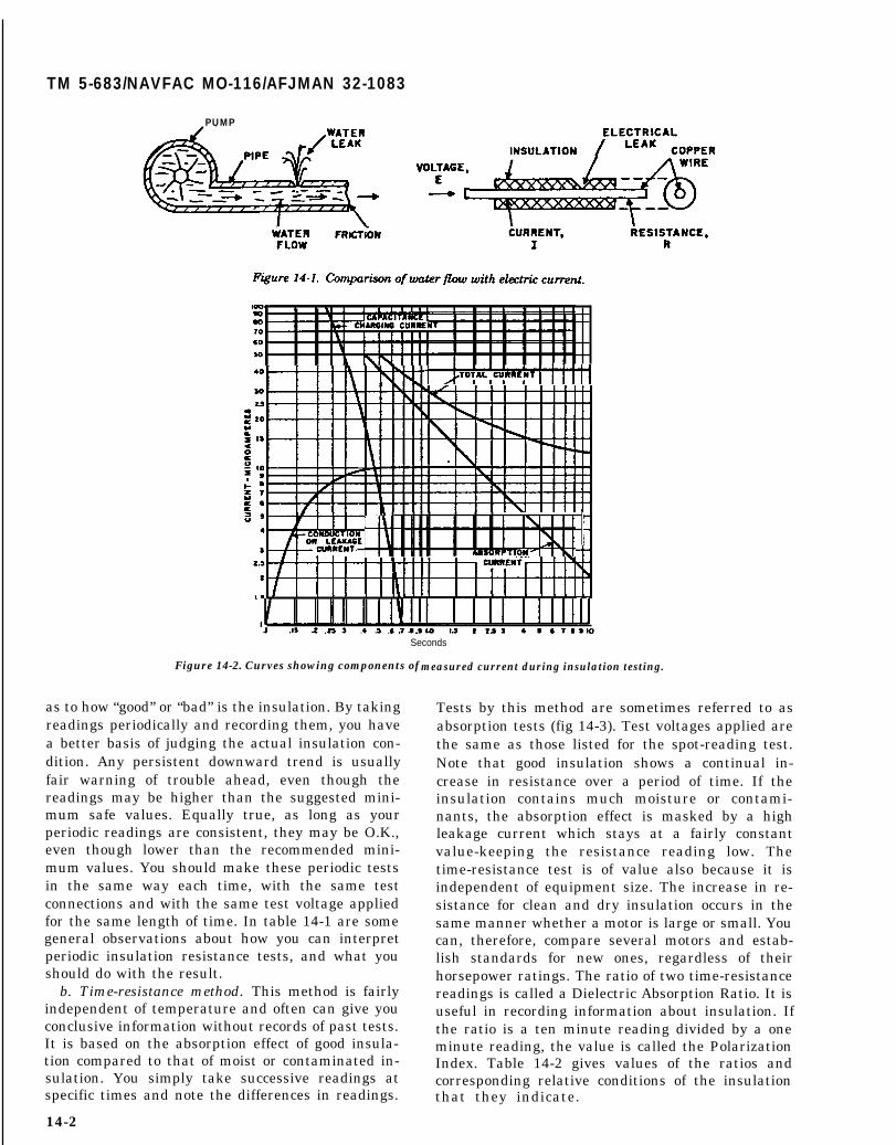
TM 5-683/NAVFAC MO-116/AFJMAN 32-1083
PUMP
Seconds
Figure 14-2. Curves showing components of measured current during insulation testing.
as to how “good” or “bad” is the insulation. By takingreadings periodically and recording them, you havea better basis of judging the actual insulation con-dition. Any persistent downward trend is usuallyfair warning of trouble ahead, even though thereadings may be higher than the suggested mini-mum safe values. Equally true, as long as yourperiodic readings are consistent, they may be O.K.,even though lower than the recommended mini-mum values. You should make these periodic testsin the same way each time, with the same testconnections and with the same test voltage appliedfor the same length of time. In table 14-1 are somegeneral observations about how you can interpretperiodic insulation resistance tests, and what youshould do with the result.
b. Time-resistance method. This method is fairlyindependent of temperature and often can give youconclusive information without records of past tests.It is based on the absorption effect of good insula-tion compared to that of moist or contaminated in-sulation. You simply take successive readings atspecific times and note the differences in readings.
14-2
Tests by this method are sometimes referred to asabsorption tests (fig 14-3). Test voltages applied arethe same as those listed for the spot-reading test.Note that good insulation shows a continual in-crease in resistance over a period of time. If theinsulation contains much moisture or contami-nants, the absorption effect is masked by a highleakage current which stays at a fairly constantvalue-keeping the resistance reading low. Thetime-resistance test is of value also because it isindependent of equipment size. The increase in re-sistance for clean and dry insulation occurs in thesame manner whether a motor is large or small. Youcan, therefore, compare several motors and estab-lish standards for new ones, regardless of theirhorsepower ratings. The ratio of two time-resistancereadings is called a Dielectric Absorption Ratio. It isuseful in recording information about insulation. Ifthe ratio is a ten minute reading divided by a oneminute reading, the value is called the PolarizationIndex. Table 14-2 gives values of the ratios andcorresponding relative conditions of the insulationthat they indicate.

TM 5-683/NAVFAC MO-116/AFJMAN 32-1083
Table 14-1. Interpreting insulation resistance test results.
CONDITION WHAT TO DO
1. Fair to high values and well- No cause for concern.maintained.
2. Fair to high values, but Locate and remedy the cause and checkshowing a constant tendency the downward trendtowards lower values.
3. Low but well-maintained. Condition is probably all right, butcause of low values should be checked.
4. So low as to be unsafe. Clean, dry-out, or otherwise raise thevalues before placing equipment inservice (test wet equipment whiledrying out).
5. Fair or high values,previously well-maintained, Make tests at frequent intervals untilbut showing sudden lowering. the cause of low values is located and
remedied; or until the values havebecome steady at a lower level but safefor operation; or until values becomeso low that it is unsafe to keep theequipment in operation.
Figure14-3. Typical curves showing dielectri absorption effecting a time-resistance or double-mading test.
14-3. Protective relay testing.
Protective relays are used to detect and isolate sys-tem abnormalities with minimum disturbance to therest of the electrical distribution system. The morecommon protective relays are the electro-mechanicaltypes. In them, a mechanical element, such as aninduction disk or magnetic plunger, moves in re-sponse to an abnormal change in a parameter of theeletrical system. This movement causes a contact inthe control circuit to operate, tripping the circuit
to be applied to each particular relay, and the testpoints. This data is often furnished on a time-current characteristic curve of a coordination study.
(4) A test instrument should be available asrecommended by the manufacturer.
(5) Most protective relays can be isolated fortesting while the electrical system is in norma op-eration. However, an operation of the breaker isrequired to ascertain that the operation of the relaycontacts will trigger the intended reaction, such asto trip the associated circuit breaker.
b. The tests to be performed are determined bythe relay to be tested. For electro-mechanical re-lays, inspection, testing and adjustment are recom-mended.
(1) Inspection. Each relay should be removedfrom its case for a thorough inspection and cleaning.
14-3

TM 5-683/NAVFAC MO-116/AFJMAN 32-1083
Table 14-2. Condition of insulation indicated by dielectric absorption ratios.
INSULATION 60/30-SECOND 10/1-MINUTE RATIOCOORDINATION RATIO (POLARIZATION INDEX)
Dangerous Less than 1
Questionable 1.0 to 1.25 1.0 to 2
Good 1.4 to 1.6 2 to 4
Excellent Above 1.6 ** Above 4 **
*These values must be considered tentative and relative - subject to experiencewith the time-resistance method over a period of time.
**In some cases, with motors, values approximately 20% higher than shown hereindicate a dry brittle winding which will fail under shock conditions or duringstarts. For preventative maintenance, the motor winding should be cleaned,treated, and dried to restore winding flexibility.
If the circuit is in service, remove one relay at atime so as no to totally disable the protection. Be-fore the relay cover is removed, excessive dirt, dustand metallic material deposited on the cover shouldbe noted and removed.Removing such material willprevent it from entering the relay when the cover istaken off. The presence of such deposits may indi-cate the need for some form of air filtering at thestation. "Fogging’’ of the cover glass should be notedand cleared. Such fogging is, in some cases, a nor-mal condition due to volatile materials being drivenout of coils and insulation. However, if the foggingappears excessive, further investigation is neces-sary. A check of the ambient temperature and thesupplied voltage and current must be compared tothe nameplate or manufactured instruction bookratings.
(2) Electrical tests. Manually close (or open) therelay contacts and observe that they perform theirrequired function; i.e., trip a breaker, reclose abreaker, etc. Apply prescribed settings or ascertainthat they have been applied to the relay. Graduallyapply current or voltage equal to the tap setting tothe relay to verify that the pickup is within speci-fied limits. If miscalibrated, the restraining spiralspring can be adjusted. The data that this testyields should be compared to previous data. Reducethe current or voltage until the relay drops out orresets fully. This test will indicate excess friction.Should the relay be sluggish in resetting or fail toreset completely, then the jewel bearing and pivotshould be examined. A magnifying glass is adequatefor examining the pivot, and the jewel bearing canbe examined with the aid of a needle which will
14-4
reveal any cracks in the jewel. Should dirt be theproblem, the jewel can be cleaned with an orangestick while the pivot can be wiped clean with a soft,lint-free cloth. No lubricant should be used on eitherthe jewel or pivot. Should evidence of overheatingbe found, the insulation should be checked and ifbrittle replaced. Withdrawal of the connection plugin drawout relays may reveal evidence of severefault currents or contaminated atmospheres, eitherof which may indicate that a change in the mainte-nance schedule is necessary.
(3) Mechanical adjustments. All connectionsshould be tight. If several connections are loose,excessive vibration may be indicated, and should becorrected. All gaps should be free of foreign materi-als, if not, inspection of the gasket is necessary.Contact gaps should be measured and the valuescompared with pervious measurements. Shouldthere be a large variation in these measurements,excessive wear may be indicated, in which case theworn parts should be replaced. It may also be foundthat an adjusting screw has worked loose and mustbe retightened. This information should be noted onthe test record. All contacts, except those not recom-mended for maintenance, should be burnished andmeasured for alignment and wipe. Relays that oper-ate after a time delay when subjected to an overcur-rent condition should have an operating time testperformed. This test is made anywhere from two toten times tap setting. The time it takes the relay totrip must coincide with the manufacturer's recom-mended operating times. If not, then relay adjust-ments should be made, if possible and the relayretested. Readjustments may be necessary until the
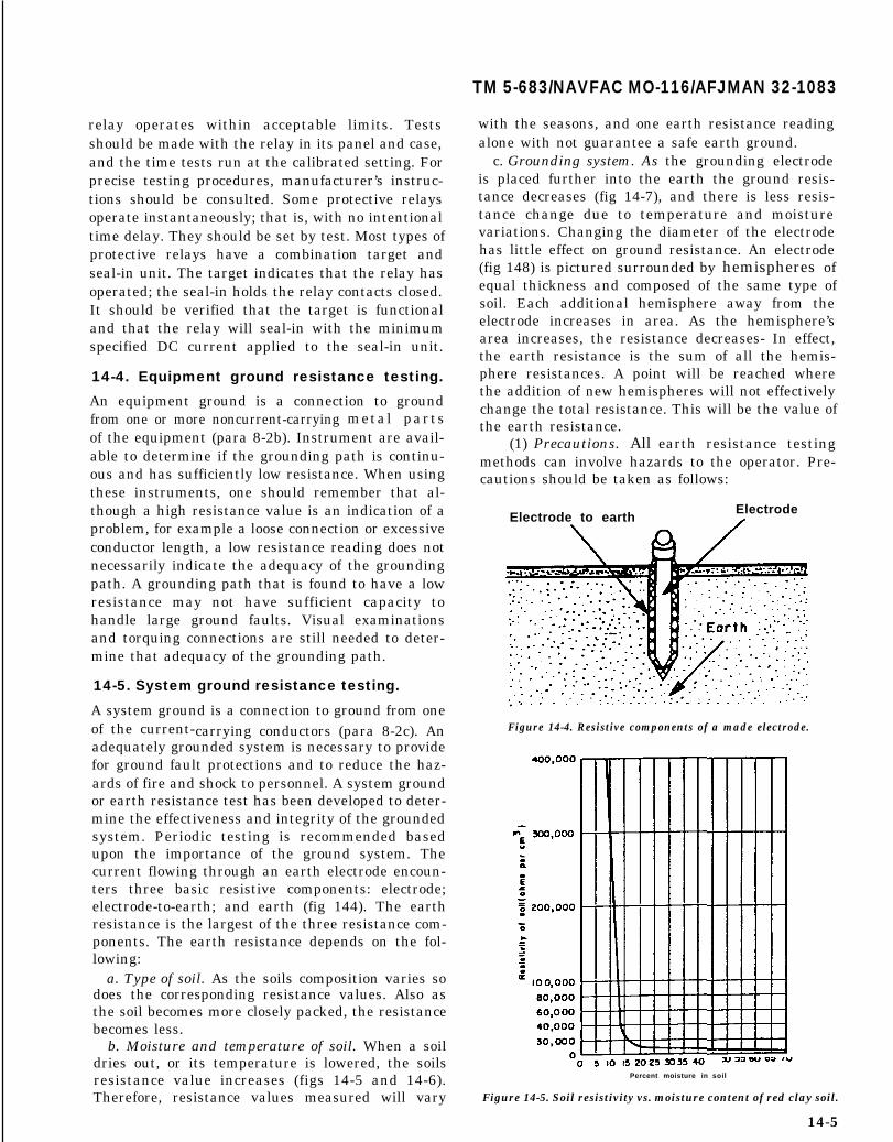
TM 5-683/NAVFAC MO-116/AFJMAN 32-1083
relay operates within acceptable limits. Testsshould be made with the relay in its panel and case,and the time tests run at the calibrated setting. Forprecise testing procedures, manufacturer’s instruc-tions should be consulted. Some protective relaysoperate instantaneously; that is, with no intentionaltime delay. They should be set by test. Most types ofprotective relays have a combination target andseal-in unit. The target indicates that the relay hasoperated; the seal-in holds the relay contacts closed.It should be verified that the target is functionaland that the relay will seal-in with the minimumspecified DC current applied to the seal-in unit.
14-4. Equipment ground resistance testing.
An equipment ground is a connection to groundfrom one or more noncurrent-carrying metal partsof the equipment (para 8-2b). Instrument are avail-able to determine if the grounding path is continu-ous and has sufficiently low resistance. When usingthese instruments, one should remember that al-though a high resistance value is an indication of aproblem, for example a loose connection or excessiveconductor length, a low resistance reading does notnecessarily indicate the adequacy of the groundingpath. A grounding path that is found to have a lowresistance may not have sufficient capacity tohandle large ground faults. Visual examinationsand torquing connections are still needed to deter-mine that adequacy of the grounding path.
14-5. System ground resistance testing.
A system ground is a connection to ground from oneof the current-carrying conductors (para 8-2c). Anadequately grounded system is necessary to providefor ground fault protections and to reduce the haz-ards of fire and shock to personnel. A system groundor earth resistance test has been developed to deter-mine the effectiveness and integrity of the groundedsystem. Periodic testing is recommended basedupon the importance of the ground system. Thecurrent flowing through an earth electrode encoun-ters three basic resistive components: electrode;electrode-to-earth; and earth (fig 144). The earthresistance is the largest of the three resistance com-ponents. The earth resistance depends on the fol-lowing:
a. Type of soil. As the soils composition varies sodoes the corresponding resistance values. Also asthe soil becomes more closely packed, the resistancebecomes less.
b. Moisture and temperature of soil. When a soildries out, or its temperature is lowered, the soilsresistance value increases (figs 14-5 and 14-6).Therefore, resistance values measured will vary
with the seasons, and one earth resistance readingalone with not guarantee a safe earth ground.
c. Grounding system. As the grounding electrodeis placed further into the earth the ground resis-tance decreases (fig 14-7), and there is less resis-tance change due to temperature and moisturevariations. Changing the diameter of the electrodehas little effect on ground resistance. An electrode(fig 148) is pictured surrounded by hemispheres ofequal thickness and composed of the same type ofsoil. Each additional hemisphere away from theelectrode increases in area. As the hemisphere’sarea increases, the resistance decreases- In effect,the earth resistance is the sum of all the hemis-phere resistances. A point will be reached wherethe addition of new hemispheres will not effectivelychange the total resistance. This will be the value ofthe earth resistance.
(1) Precautions. All earth resistance testingmethods can involve hazards to the operator. Pre-cautions should be taken as follows:
Electrode to earthElectrode.
Figure 14-4. Resistive components of a made electrode.
Percent moisture in soil
Figure 14-5. Soil resistivity vs. moisture content of red clay soil.
14-5

TM 5-683/NAVFAC MO-116/AFJMAN 32-1083
Figure 14-6. Soil resistance vs. temperature of clay soil.
0 1 2 3 4 5 6 7 8 9 10
Depth of electrode in feet
Figure 14-7. Soil resistance vs. depth of electrode.
(a) When testing earth resistance, rememberthat during fault conditions, dangerous voltagesmay exist between a system ground and a remotepoint being tested. Care should be taken when con-necting leads and test equipment, Avoid as muchcontact with the leads and probes as possible.
(b) Most of the earth resistance is locatedclose to the grounding system due to the “hemi-sphere effect”. When a ground fault occurs, the ma-jority of the voltage drop is close to the system.Caution should be used when approaching a liveground.
Earth surface
E l e c t r o d e /
Hemispheres
Figure 14-8. Earth electrode with hemispheres.
(c) At stations where the fence is not con-nected to the station ground, a dangerous voltagecan develop under fault conditions between thefence and station ground. Do not touch both at thesame time.
(d) Surge and switching effects in transmiss-ion lines may induce dangerous spikes in the testleads strung under the line. Care should be exer-cised in handling these test leads.
(e) Tests should not be performed during athunderstorm.
(2) Protection. Rubber gloves, boats, an insu-lated platform, etc., capable of protecting the opera-tor against full-line voltage, are recommended forprotection.
(3) Fall-of-potential method. The fall-of-potentiaI method is probably the most widely usedand accepted of all methods available. It can beused most practically on small and medium sizedsystems. A ground resistance test set is used. Meas-ure the earth resistance of the earth system (E) (fig14-9). In this method, greater pin spacing is re-quired for testing ground grids and multiple rodinstallations than for single rod testing. To accom-plish this, current is supplied between the currentelectrode (CE) and the system E under test. A volt-meter measures the voltage drop between the po-tential electrode (PE) and the system. By movingthe potential electrode between E and CE, variousvoltages will be recorded and corresponding resis-tance values found. When the resistance values areplotted versus distance, the earth resistance can beseen to increase as the potential electrode movesaway from the system ground, but at a decreasingrate of change. This results because each new outerhemisphere of earth around the system E adds asmaller amount of resistance to the total earth re-sistance as previously discussed. At a point, usually
14-6

Figure 14-9. Fall-of-potential method graph.
about 62 percent of the total distance between the.current probe and the system, the earth resistanceshould become almost constant. This is the pointwhere the earth resistance of the system is mostaccurate.
14-6. Battery specific gravity test.
Great care should be exercised when sampling andhandling battery electrolyte. Since it may containacid it can cause irritation if it comes in contactwith the skin, and could cause blindness if it weresplashed in the eye. Electrolyte is also a conductorand can cause short circuits if splashed over the cellterminals. When specific gravity of a battery is be-ing measured, wear acid resistant eye protection,gloves and apron. It is also available to wear rubberslippers or boots when working with batteries.When sampling the cells’ electrolyte:
a. Place a hydrometer tube (or hose) firmly intothe mouth of the cell electrolyte withdrawal tube(fig 14-10).
b. Slowly squeeze the hydrometer bulb so as toforce air into the withdrawal tube, clearing it ofelectrolyte.
c. Release hand pressure on the hydrometer bulballowing electrolyte to draw up into the glass barrel ofthe hydrometer. Sufficient electrolyte must be with-drawn to allow the hydrometer float to float freely.
TM 5-683/NAVFAC MO-116/AFJMAN 32-1083
d. The hydrometer must be held vertical suchthat the float is free and not in contact with thesides of the hydrometer barrel.
e. With hydrometer floating freely, read andrecord the float scale point at the true liquid level(fig 14-11). The level at point A is 1.210; at point B,where the float is lower in the liquid, the reading is1.183.
14-7. Infrared inspection.
Infrared thermography is the process of making in-framed radiation visible and measurable. This radia-tion is emitted by all objects as heat, which is con-stantly being absorbed and re-emitted byeverything including ourselves. When an electricalconnection is loose or corroded, it is said that theconductor has developed a high resistance connec-tion. A high resistance connection produces heatwhich can be detected through infrared ther-mography. Loose connections should be tightenedand corroded connections cleaned. Cables with poorinsulation should be repaired or replaced. Infraredinspections of electrical equipment help to reducethe number of costly and catastrophic failures andunscheduled shutdowns. Such inspections per-formed by qualified and trained personnel on ener-gized equipment may uncover potentially danger-ous situations. Proper diagnosis and remedialaction have also helped to prevent major losses. Theinstruments most suitable for infrared inspectionsare of the type that use a scanning technique toproduce an image of the equipment being inspected.These devices display a picture, where the “hotspots” appear as bright spots. Infrared surveys maybe performed by military facilities personnel if theyown infrared imaging instruments and adhere tothe manufacturer’s instructions. Routine infraredsurveys should be performed at the very least everyyear during periods of maximum possible loading.These surveys should be well documented and ifcritical, impending faults exist, the electrical super-visor should be notified and corrective actionstaken.
14-7

TM 5-683/NAVFAC MO-116/AFJMAN 32-1083
TUBE
Figure 14-10. Sampling the cell electrolyte.
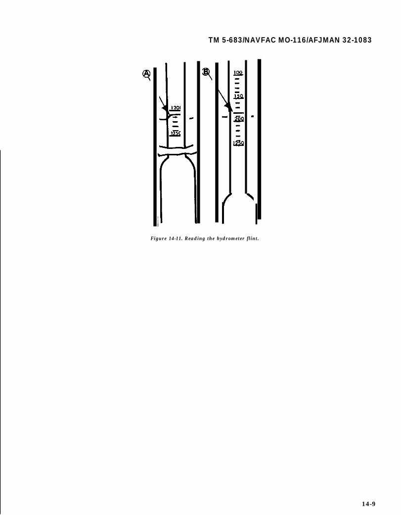
TM 5-683/NAVFAC MO-116/AFJMAN 32-1083
Figure 14-11. Reading the hydrometer flint.
14-9

TM 5-683/NAVFAC MO-116/AFJMAN 32-1083/
CHAPTER 15
MAINTENANCE SCHEDULES
15-1. Personnel.
This chapter sets up timetables for maintenanceactions. Whenever the electrical shop/electrician orthe electrical supervisor is mentioned, it refers tothe appropriate shop or individual responsible tothe facilities engineer, the public works officer, thebase civil engineer or to the appropriate individualhaving responsibility for the maintenance of realproperty facilities. The user or using service is theoccupant actually benefiting from the service. Themaintenance group consists of personnel who areresponsible for the routine scheduled maintenanceof real property facilities. This group may or maynot have affiliated electrical personnel. The opera-tor has the responsibility for starting, operating andsecuring the equipment when not in use.
15-2. Responsibilities.
The responsibility for maintenance of all real prop-erty electrical items will be assigned to the electri-cal shop/electrician. For example, the electricalshop/electrician is responsible for electric motorsand pertinent controls that power such equipmentas air conditioners, boilers and water pipes, eventhough the overall responsibility for the poweredequipment is assigned to other shops. While most ofthe electrical maintenance will be accomplished bypersonnel in the electrical shop/electrician, it is of-ten more logical and economical to have certaintasks, particularly preventive maintenance, accom-plished by other personnel. Such tasks will be deter-mined by the electrical supervisor who, through co-ordination and inspection, assures adequacy of thework performed. Often the user or other shops havethe capability to perform periodic electrical mainte-nance. For example, air conditioning mechanicsgenerally have the capability to service motors andcontrols associated with their responsibilities. Indesignating tasks for others, the electrical supervi-sor will be guided by their capabilities. In tables15-3 and 15-4 entries in the column headed "respon-sibility” indicate the suggested groups that might beexpected to perform the listed maintenance work attypical military installations. These suggested as-signments may be changed to suit local conditionsand capabilities.
15-3. Frequencies and procedures.
Of many factors involved in reliability of equip-ment, timely and high quality preventive mainte-
nance are very important. A properly developed andimplemented electrical preventive maintenanceprogram minimizes equipment failure. However,performing maintenance at too frequent intervals isexpensive, both in labor and material costs, butsometimes this can also cause failure. Thus there isa general optimum interval between scheduled pre-ventive maintenance instances. Table 15-1 lists thedata regarding percentage of failures since lastmaintenance. From this table, the following conclu-sions regarding maintenance frequency can bedrawn.
a. One year or less interval for scheduled main-tenance of all electrical equipment combined as ageneral rule is desirable.
b. One year interval for circuit breaker is appro-priate.
c. Two year interval for motors (DC motors mayneed more frequent maintenance compared to ACmotors) should be sufficient (bearings may needmore attention).
d. Two year interval for transformers.e. This interval needs to be adjusted for specific
equipment, type of duty, operating environment andquality of maintenance. Quality of maintenance canbe factored into the failure rate by using multipliersshown in table 15-2. For example, poor quality ofmotor maintenance will double (1.97 in table 15-2)its failure rate for the same maintenance interval,whereas perfect maintenance reduces the failurerate (given in table 15-4) by 16 percent. The preven-tive maintenance inspection and service frequenciesthat follow (tables 15-3 and 15-4) are guides whichmay be modified to meet local requirements. When-ever manpower constraints prevent the facilitiesmanager in following the suggested maintenancefrequency, procuring outside contractors is an op-tion. However, if budgetary constraints make thisan impossible task, then maintenance should bescheduled as close to the suggested interval as pos-sible. Exceptions should not be made for maintain-ing equipment and facilities which serve criticalloads and functions. The maintenance group or usershould immediately report any defects beyond theirrepair capability to the electrical shop/electrician.They should keep records of all defects in the sys-tem and corrective actions taken to repair thesedefects. The table inputs are self-explanatory. Thereferences are to sections in this manual coveringprocedures of inspections and maintenance.
15-1
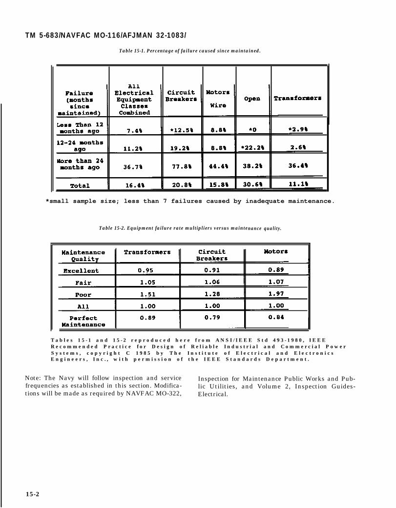
TM 5-683/NAVFAC MO-116/AFJMAN 32-1083/
Table 15-1. Percentage of failure caused since maintained.
*small sample size; less than 7 failures caused by inadequate maintenance.
Table 15-2. Equipment failure rate multipliers versus maintenance quality.
T a b l e s 1 5 - 1 a n d 1 5 - 2 r e p r o d u c e d h e r e f r o m A N S I / I E E E S t d 4 9 3 - 1 9 8 0 , I E E ER e c o m m e n d e d P r a c t i c e f o r D e s i g n o f R e l i a b l e I n d u s t r i a l a n d C o m m e r c i a l P o w e rS y s t e m s , c o p y r i g h t C 1 9 8 5 b y T h e I n s t i t u t e o f E l e c t r i c a l a n d E l e c t r o n i c sE n g i n e e r s , I n c . , w i t h p e r m i s s i o n o f t h e I E E E S t a n d a r d s D e p a r t m e n t .
Note: The Navy will follow inspection and service Inspection for Maintenance Public Works and Pub-frequencies as established in this section. Modifica- lic Utilities, and Volume 2, Inspection Guides-tions will be made as required by NAVFAC MO-322, Electrical.
15-2

TM 5-683/NAVFAC MO-116/AFJMAN 32-1083/
RESPONSIBILITY
Maintenance Group(Operator/Electricians
User
Electrician
Electrician
Electrician
Table 15-3. Interior wiring and lighting system.
FREQUENCY
Each scheduledbuilding visit
AS Required
As required.
As required.
Monthly orAnnually
CHECK
Unauthorized or nonstandard attachments
Defective convenience outlets and switches.
Improper cords.
Proper fuse sizes in panels.
Overheating of panels.
Any condition likely to cause fire. Check battery-
type emergency lights and replacement lamps.Check for Iamps larger than standard prescribedfor outlet.
Replace burnt out lamps in hard-to-reach places.(To be accomplished by electrical shop if specialequipment such as ladder trucks are needed).
Panels for circuit idenificaton and accessibility.
Replace blown fuses.
Replace burnt out or defective incandescent lamps.
Replace burnt out fluorescent lamps if personnelhave been instructed in this function and if assignedto user. Promptly replace or report defectivelamps since a lamp approaching bum out flashes onand off, causing overduty on auxiliary equipment.
Make repairs and adjustments to systems whenmalfunctions are reported. Ensure that all workcomplies with the NEC
Check ground resistance for special weaponsfacilities at request of user.
Check for low voltages and/or low power factor.
Inspect station (substation switchgear or UPS) asfollows:
(1) Check electrolyte level and add distilled water ifneeded.(2) Check charging rate. Adjust charging rate asnecessary to maintain proper specific gravity.(3) Test for proper operation under simulatedpower interruption. Check maintenance freebatteries. Check voltage, check and cleanterrminal/connection.
REF.
5-4-4
9-7
9-6
5-4-1
5-4-4
9-6
9-6
14-5
13-2
2-8-3
15-3

Table 15-3. Interior wiring and lighting system-continued.
RESPONSIBILITY FREQUENCY CHECK REF.
Electrician As required Infrared scan, if available, and inspectbuildings for defective wiring and looseconnections. Tighten or replace, asnecessary. Check grounds for continuity.Check all systems for abnormal conditions.Correct discrepancies. 14-4
Inspect disconnects, cabinets, panels and loadcenters. Tighten connectionss. Clean panels.Check fuse sizes. Manually operate switches chapterand breakers. 5
Use ohmmeter to detect grounds. Eliminatedefects. 13-2
Check and correct unbalance of loads
Clean transformers, ducts and capacitors. chapter3, 24,2-8-2.
Electrician As required Clean lighting fixtures whenever foot-candlereadings drop 20 to 25%. This will beatapproximate ly annual intervals in ordinaryoffices, longer in clean rooms, and at lesserintervals for dirty areas. Work should beaccomplished by custodial or by user ifwithin capabilities.
9-5
Electrician Every Year Test power circuit breakers and protective 2-8-8relays
Test metering and indicating instruments 2-8-4, 2-8-5, 2-8-7
Electrical Shop Every 5 years Test molded case feeder and main circuit 5 4 3breakers in main panelboards.
Test single phase watt hour meters. 2-8-5
15-4

RESPONSIBILITY
User
Operator
Electrician
Electrician
Electrician
Operator
Table 15-4. Electric motors and controls.
FREQUENCY
As Required
As Required
Weekly
Aa required
Annually
Annually
Quarterly
Annually
CHECK
Report any unusual conditions. Clean and lubricate thosemotors assigned to the team for this purpose
Kcep area around motors free from obstructions.
Report any:(1) Unusual noises(2) Overheating(3) Accumulation of dust and moisture(4) Sparking(5) Difficulty in coming up to speed
Check oil level on sleeve bearing motors with oil gages.Fill, if necessary. Add oil and check only when motor is
stopped.
Check belts for suitable slack.. Adjust as necessary.
Check brushes in holders for fit and free play. Tightenbrush studs. Replace brushes if necessary.
Inspect commutator for high mica. glaze, roughness orscratches.
Check for vibration.
Check shunt, series, and commutating fields or tightness.Check cable connections.
Check for bearing wear. Lubricate ball bearings.
Measure insulation resistanc e on motars over 10 hp.Check winding insulation for cracks or other defects.Make sure windings are dry.
Check air gap between rotor and stator on motors over 1horsepower. Use long feeler gages for this purpose. Arecord of yearly checks will give a picture of bearing wear.A variation of 10 percent from one year to the next is
permissible.
Cheek belts to insure that they are no tighter than necessaryto insure against slipping. Check chains for evidence ofwear.
Maintain proper alignment between motor and machine thatit drives.
Check motor to see that end thrust is not excessive andshaft has a reasonable axial float.
Lubricate motors. Flush and refill oil reservoirs. USelubricants recommended by equipment manufacture.Frequency of lubrication depends on usage of motors.Grease lubricated ball or roller bearing motors may requirelubrication only once a year if motor is operated lightly,but as often as every 2 months if hard driven. Do not mixgreases of different type or specifications.
4-4
4-2-5-2-2
4 - 3 4 2
4 - 3 4 3
4 4 4
4-3
4-2-s-2-1
4-2-5-3
4-2-5-1
4-4-3
4-4-4
4-4-4
4-2-5-2
15-5

TM 5-683/NAVFAC MO-116/AFJMAN 32-1083/
Table 15-4. Electric motors and controls-continued.
15-6
TM 5-683/NAVFAC MO-116/AFJMAN 32-1083
APPENDIX A
REFERENCES
A-1. Government PublicationsDepartment of the Army
AR 420-16 Facilities Engineering; ReportsAR 420-43 Electrical ServicesAR 420-90 Fire ProtectionTM 5-609 Military Custodial Services ManualTM 5-682 Facilities Engineering; Electrical Facilities SafetyTM 5-684 Facilities Engineering Electrical Exterior FacilitiesTM 5-695 Maintenance of Fire Protection SystemsTM 5-760 Interior WiringTM 5-811-1 Electric Power Supply and DistributionTM 5-811-2 Electrical Design; Interior Electrical SystemTM 5-811-3 Electrical Design; Lightning and Static Electricity Protection
Department of the Navy11014.22c Technical Coordination and Support of the Maintenance of Public Works and Public
Utilities11014.29B Public Works Types Maintenance Problems Arising from Field Operation ExperienceMO-117 Fire Alarm and Sprinkler MaintenanceMO-200 Electrical Exterior FacilitiesMO-201 Operation of Electric Power Distribution SystemMO-202 Control of Electromagnetic Interference on Overhead Power LinesMO-203 Wire Communication and Signal System MaintenanceMO-204 Electrical Power System AnalysisMO-205 Central Heating and Steam-Electric Generating PlantsMO-207 Operation and Maintenance of Internal Combustion Engines
Department of the Air ForceAFIND 17 Air Force Occupational Safety and Health (AFOSH) Standards, Department of
Labor Occupational Safety and Health (OSHA) Standards, and National Insti-tute for Occupational Safety and Health (NIOSH) Publication
API 32-1062 Management of Electric Power Plants and GeneratorsAFJMAN 32-1080 Electric Power Supply and DistributionAFJMAN 32-1081 Electrical Design, Interior Electrical SystemsA.FM 88-9 Chap. 3, Electrical Design, Lightning and Static Electricity ProtectionAFJ MAN 32-1082 Facilities Engineering, Electrical Exterior FacilitiesAFI 32-1063 Electric Power SystemsAFI 32-1065 Grounding SystemsAFI 41-203 Electrical Safety in Medical FacilitiesAFI 32-1044 Visual Air Navigation Systems
A-2. Nongovenment PublicationsAmerican National Standards Institute (ANSI), National Electric Safety Code, Standard C2, 1993, 1430
Broadway, New York, NY 19918Illuminating Engineer Society (IES), IES Handbook, 1987, 345 East 47th Street, New York, NY 10017Institute of Electrical and Electronics Engineers (IEEE), Guide for Field Testing of Relaying Current
Transformers IEEE Standard C57.13-1-1981, 345 East 47th Street, New York, NY 10017Institute of Electrical and Electronics Engineers (IEE), IEEE Recommended Practice for Grounding of
Industrial and Commercial Power Systems, IEEE Standard 142-1982, 345 East 47th Street, New York, NY10017
Institute of Electrical and Electronics Engineers (IEEE), ZEEE Recommended Practice for Power SystemsAnalysis, IEEE Standard 399-1980, 345 East 47th Street, New York, NY 10017
Institute of Electrical and Electronics Engineers (IEEE), IEEE Recommended Practice for Protection and
A-1
Coordination of Industrial and Commercial Power Systems, IEEE Standard 242-1986,345 East 47th Street,New York, NY 10017
Institute of Electrical and Electronics Engineers (IEEE), IEEE Recommended Practice on Surge Voltagesin Low Voltage AC Power Circuits, IEEE Standard C62.41-1991, 345 East 47th Street, New York, NY 10017
National Electrical Manufacturers Association (NEMA), Enclosures for Electrical Equipment, NEMAStandard 250-1991, 2101 L Street, NW, Washington, DC 20037
National Electrical Manufacturers Association (NEMA), Guidelines for Inspectionn and PreventativeMaintenance of Molded Case Circuit Breakers Used in Commercial and Industrial Applications, NEMAStandard AB 4-1991, 2101 L Street, NW, Washington, DC 20037
National Fire Protection Association (NFPA), National Electrical Code, NFPA publication #70, 1990, 1Batterymarch Park, Quincy, MA 02269
National Fire Protection Association (NFPA), Recommended Practice for Electrical Equipment Mainte-nance, NFPA publication #70B, 1990, 1 Batterymarch Park, Quincy, MA 02269
- -
National Fire Protection Association (NFPA), Installation, Maintenance, and Use of Protective SignalingSystems, NFPA publication #72, 1990, 1 Batteryrmarch Park, Quincy, MA 02269
National Fire Protection Association (NFPA), Fire Tests of Building Construction and Materials, NFPApublication #251, 1990, 1 Batterymarch Park Quincy, MA 02269
Underwriters Laboratories (UL), UL Standard for Safety: Molded Case Circuit Breakers and CircuitBreaker Enclosures, UL #489-1991, 207 East Ohio Street, Chicago, IL 60611
A-2

TM 5-83/NAVFAC M-116/AFJMAN 32-1083
The proponent agency of this publication is the United StatesArmy Center for Public Works. Users are invited to send com-ments and suggested improvements on DA Form 2028 (Recom-mended Changes to Publications and Blank Forms) directly toDirector, U.S. Army Center for Public Works, Attn: CECPW-EE,7701 Telegraph Rd., Alexandria, VA 22315-3862.
By Order of the Secretaries of the Army, the Navy, and the Air Force:
DENNIS J. REIMER
Official:General, United States Army
Chief of Staff
D. J. NASHRear Admiral CEC, USN Commander,Naval Facilities Engineering Command
OFFICIAL EUGENE A LUPIA, Maj General, USAFThe Civil Engineer
Distribution:Army: To be distributed in accordance with DA Form 12-34-E, block
0695 requirements for TM 5-683.Air Force: F
*U.S. G. P.O. : 1996-404-611 :20046