TM-318 / 020674 / OPERATION AND MAINTENANCE MANUAL ... · SAFETY INSTRUCTIONS AND WARNINGS FOR...
98
:. : TM-318 / 020674 / OPERATION AND MAINTENANCE MANUAL with ILLUSTRATED PARTS LIST for HOBART 400 HZ AC GENERATOR Synchronous Motor Driven with Static Voltages Regulator Manufactured by MOTOR GENERATOR DIVISION HOBART BROTHERS COMPANY I TROY, OHIO 45373
Transcript of TM-318 / 020674 / OPERATION AND MAINTENANCE MANUAL ... · SAFETY INSTRUCTIONS AND WARNINGS FOR...

:.
:
TM-318 /
020674 /
OPERATION AND MAINTENANCE MANUAL
with
ILLUSTRATED PARTS LIST
for
HOBART 400 HZ AC GENERATOR
Synchronous Motor Driven
with
Static Voltages Regulator
Manufactured by
MOTOR GENERATOR DIVISION
HOBART BROTHERS COMPANY I
TROY, OHIO 45373


r
SAFETY INSTRUCTIONS AND WARNINGS FOR ELECTRICAL POWER EQUIPMENT
ELECTRIC SHOCK can kill. Do not touch live electrical parts.
FUMES AftID GASES can be fire and health hazards. Ventilate all fumes and exhaust gases to the outside.
ELECTRIC ARC FLASH can injure eyes, burn skin, cause equipment damage, and ignite combustible material. Do not use power cables to break load and be sure tools don’t cause short circuits.
IMPROPER PHASE CONNECTION, PARALLELING, OR USE can damage this and attached equipment.
MOVING PARTS can cause serious injury. Keep clear of moving parts.
IMPORTANT - Protect yourself and others. Read and understand all the instructions in this Operating/Instruction Manual before installing, operating, or servicing this equipment. Keep this manual available for future use by all operators.
A. GENERAL Equipment that supplies electrical power can cause serious injury or death, or damage to other equipment or
property, if the operator does not strictly observe all safety rules and take precautionary actions. Safe practices
have developed from past experience in the use of power source equipment. Certain of the practices below apply to
engine driven equipment.
B. SHOCK PREVENTION
Bare conductors, or terminals in the output circuit, or ungrounded, electrically-live equipment can fatally shock a
person. Have a competent electrician verify that the equipment is adequately grounded and learn what terminals and parts are electrically HOT. Use proper safety clothing, procedures, and test equipment.
The electrical resistance of the body is decreased when wet, thus more easily permitting dangerous currents to flow
through it. When inspecting or servicing equipment, do not work in damp areas without being extremely careful.
Stand on dry rubber mat or dry wood, use insulating gloves that are effective when dampness or sweat cannot be
avoided. Keep your clothing dry and never work alone.
1. Installation and Grounding of Electrically Powered Equipment - Electrical equipment must be installed and maintained in accordance with the National Electrical Code, ANSI/NFPA 70, and other applicable codes. A power disconnect switch or circuit breaker must be located at the equipment. Check the nameplate for voltage,
frequency, and phase requirements. If only 3-phase power is available, connect any single-phase rated equipment to only two wires of the 3-phase line. DO NOT CONNECT the equipment grounding conductor (lead) to the third live
wire of the 3-phase line, as this makes the equipment frame electrically HOT, which can cause a fatal shock. ---- --- ---
Be sure to connect the grounding lead, if supplied in a power line cable, to the grounded switch box or building ground. If not provided, use a separate grounding lead. Be certain that the current (amperage) capacity of the
grounding lead will be adequate for the worst fault current situation. Refer to the National Electrical Code ANSI/
NFPA 70 for details. Do not remove plug ground prongs. Use correct mating receptacles.
2. Output Cables and Terminals - Inspect cables often for damage to the insulation and the connectors. Replace
or repair cracked or worn cables immediately. Do not overload cables. Do not touch output terminal while equip-
ment is energized. I
Instruction 910082
Nov 16182 Revised
Page 1

C. FIRE AND EXPLOSION PREVENTION
Fire and explosion are caused by electrical short circuits, combustible material near engine exhaust piping, misuse
of batteries and fuel, or unsafe operating or fueling conditions.
1. Electrical Short Circuits and Overloads - Overloaded or shorted equipment can become hot enough to cause
fires either by self destruction or causing nearby combustibles to ignite. Provide primary input protection to re-
move short circuited or heavily overloaded equipment from the line.
2. Battery - Batteries may explode and/or give off flammable hydrogen gas. The acid and arcing from a ruptured
battery can cause fires and additional failures. When servicing, do not smoke, causing sparking, or use open flame
near the battery.
3. Encrine Fuel - Use only approved fuel container or fueling system. Fires and explosions can occur if the fuel
tank is not grounded prior to and during fuel transfer. Shut unit DOWN before removing fuel tank cap. Do not
completely fill tank. Heat from the equipment may cause fuel expansion overflow. Remove all spilled fuel im- mediately including any that penetrates the unit. After cleanup, open equipment doors and blow fumes away with compressed air.
D.
E.
F.
TOXIC FUME PREVENTION
Carbon Monoxide - Engine exhaust fumes can kill and cause health problems. Pipe or vent the exhaust fumes to a suitable exhaust duct or outdoors. Never locate engine exhausts near intake ducts or air conditioners.
BODILY INJURY PREVENTION Serious injury can result from contact with fans, belts, and pulleys inside the equipment. Shut DOWN equipment for inspection and routine maintenance. When equipment is in operation use extreme care in doing necessary
troubleshooting and adjustment.
MEDICAL AND FIRST AID TRFATMFNT
First aid facilities and a qualified first aid person should be available for each shift for immediate treatment of all
injury victims. Electric shock victims should be checked by a physician and taken to a hospital immediately if any abnormal signs are observed.
Call physician immediately. Seek additional assistance and use First Aid techniques recommended
by American Red Cross until medical help arrives.
IF BREATHING IS DIFFICULT, give oxygen, if available, and have victim lie down. FOR ELEC-
TRICAL SHOCK, turn off power. Remove victim; if not breathing, begin artificial respiration,
preferably mouth-to-mouth. If no detectable pulse, begin external heart massage. Call Emergency
Rescue Squad immediately.
G. EQUIPMENT PRECAUTIONARY LABELS
Inspect all precautionary labels on the equipment monthly. Order and replace all labels that cannot be easily read. I
1 1 3. Service and Maintenance - This equipment must be maintained in good electrical and mechanical condition
to avoid hazards stemming from disrepair. Report any equipment defect or safety hazard to your supervisor and discontinue use of the equipment until its safety has been assured. Repairs should be made by qualified personnel
only. Shut OFF all power at the disconnecting switch or line breaker before inspecting or servicing the equipment. Lock switch OPEN (or remove line fuses) so that power cannot be turned ON accidentally. Disconnect power to
equipment i I’ .
rt IS out of service. If troubleshooting must be done with the unit energized, have present another per- son trained in turning off the equipment and providing or calling for first aid.
EMERGENCY FIRST AID
Page 2 Instruction 910082 Revised Nov 16182
FORART
B $MOTOR GENERATOR DIVISION a “c
QD ! HOBART BROTHERS COMPANY
% z Q. .q,+
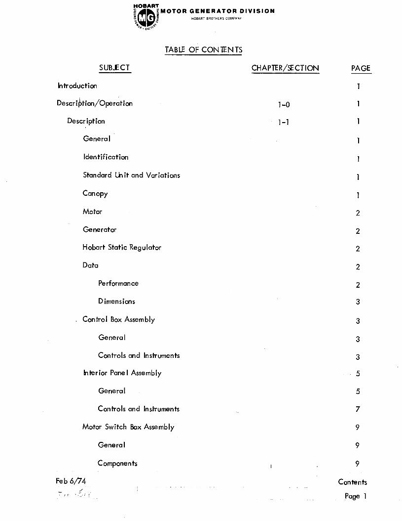
TABLE OF CONTENTS
SUBJECT CHAPTER/SECTION PAGE
Introduction
Description/Operation
Description
General
Identification
Standard Unit and Variations
Canopy
Motor
Generator
Hobart Static Regulator
Data
Performance
Dimensions
Control Box Assembly
General
Controls and Instruments
Interior Pane I Assembly
General
Controls and Instruments
Motor Switch Box Assembly
Genera I
Components
1-O
l-1
I
Fe b 6/‘74 Contents
Page 1

FOBART
I
QD
;MOTOR GENERATOR DIVISION z : HOBART BROTHERS COMPANY
“0 2
B . B ,,d-
TABLE OF CONTENTS (CONT’D)
SUBJECT
Power Module Assembly
General
Components
Preparation for Use
Genera I
Wiring
Motor Switch Overload Coils
Mounting Installation of Synchronous Motor-Driven
Generator Sets
Operation
Genera I
Remote Control
Variations
Servicing
Maintenance, Inspection/Check
Genera I
Inspection, Testing and Repair
Trouble Shooting
Trouble Shooting Procedures
General
Trouble Shooting Chart
Equipment for Trouble Shooting
Contents
Page 2
CHAPlER/SECTI,ON
l-l
l-2
l-3
2-o
2-l
3-O
3-l
PAGE
12
12
12
1
1
1
1
2
1
1
2
2
1
1
1
1
1
1
1
1
1

SUBJECT CHA PTER/SECT ION PAGE
FOBART
8 5
;MOTOR GENERATOR DIVISION
3 QD
3 HOBART BROTHERS COMPANY
% 4. 8ud
TABLE OF CONTENTS (CONT’D.)
Safety
’ Diagrams
Connections and Wiring
Chart
II lustrated Parts List
Introduction
Genera I
Purpose
Arrangement
Explanation of Parts List
Manufacturer ‘s Codes
Explanation of Manufacturer’s (Vendor) Code List
Parts List
Explanation of Parts List Arrangement
Symbols and Abbreviations
Feb 6/;74
May 12/75 Revised
3-l
4-o
4-l
4-2
4-3
1
2
2
3 thru 8
1
1
1
1
1
1
1
I
Contents
Page 3

Con tents
Page 4
GENERATOR DIVISION HOBART BROTHERS COMPANY
Fe b 6/74

HOBART z J
QD
$MOTOR GENERATOR DIVISION : z HOBART BROTHERS COMPANY
“0
b. B,,\6
INTRODUCTION
This manual contains operation and service information and instructions for Hobart 400-Hz
Ground Power Generating hit, driven by a synchronous motor. Specification numbers
and model numbers for each model covered by this manual are listed below. See Data,
sub-seption 8, page 2, this Section, for complete details on various units.
Specs. 4576A (S-4576A) Mode I 32 1 O-50
Specs. 4713A (S-4713A) Model 3210
Specs. 4820A (S-4820A) Mode I 3209-50
Specs. 4910B (S-4910B) Model 3209
In addition to the standard unit,, the manual also covers variations to the basic specifications,
which are designated by a numerical suffix to the specification number, on the nameplate.
A sub-section entitled “Variations” in Chapter 1 explains these variations, and will include
any such new variations as they are added in the future.*
The manual is in no way presented as a text book on electricity or electronics. Its primary
purpose is to provide information and instructions to experienced operators, electricians
and mechanics who have never seen nor operated this particular generator set. It is the
intent of the manual to guide and assist operators and maintenance personnel in the proper
use and care of the equipment.
Use of the manual should not be put off until a trouble or need for help develops. Read the
instructions before starting the unit. Learn to use the manual and to locate information con-
tained in it. Each page is identified in the lower outside corner by the chapter and section
number in which it appears. Each new section starts with page 1. The figure numbers with-
in the’manual are numerically consecutive throughout the manual, regardless of the section
in which they appear.
In addition to operation and maintenance instructions, the manual containsan Illustrated
Parts List in Chapter 4. A collection of manufacturer’s I iterature is supplied as part of the
information package;
* From time-to-time, specialized use of this equipment may require the addition of
other appropriate instructions and parts lists (VARIATIONS) to the basic manual.
Individual pages that specifically describe ‘the variation are inserted at the front of this
manual as ADDENDUM SHEETS.
I
Introduction
Page 1


FOBART
e a
QD
gMOTOR GENERATOR DIVISION
i HOBART BROTHERS COMPANY “0
b. ,,,I++
CHAPTER 1. DESCRIPTION/OPERATION
SECTION 1. DESCRIPTION
1. The 400-Hz AC generator set is a self-contained motor generator set, complete with
all controls, instruments and protective devices necessary for manual or fully automatic
0 ration. I= It is designed to utilize standard line power (either 50 or 60 hertz) to
generate power for providing ground service to aircraft, requiring 400-Hz power.
The’ motor and generator rotors are mounted on a common shaft supported at the ends
by ball bearings. A centrifugal fan is mounted on the shaft between the motor and
generator rotors. In operation, the fan draws air in axial ly from the outer ends of the
housing, over the rotor and stator windings, and discharges it radially through a duct
at the center of the housing. The housing is of two-piece construction, bolted together
circumferentia-lly at the middle to facilitate removal when necessary for service or re-
pair of enclosed parts. The entire unit is mounted on a welded structural stee I frame.
2. Identification
A nameplate bearing SPECS, MODEL and SERIAL numbers of the unit is located
on or near the generator control pane I. Parts orders or inquiries regarding this
equipment must refer to these numbers. Direct all parts orders and correspondence
to:
MOTOR GENERATOR DIVISION
HOBART BROTHERS COMPANY
TROY , OH IO 45373
U.S.A.
3. Standard lktit and Variations
As stated above, the standard 400-Hz AC generator is a self-contained, stationary
unit identified by one of the specification (S) numbers listed in lntroductioni
Page 1. Variations to the standard models are identified by VAR. numbers. A
variation provides for motor switch 220-V input power on some models which are
380-volt standard, and a variation provides for mounting the unit on a trailer for
portable use. See the sub-section on VARIATION S, Section 1-3, page 2.
If other variations become available, or if changes are made, new information will
be added at the end of the sections in which the information would normally be located.
4. Canopy
A sheet metal enclosure, identified as a canopy, provides protection for the electric
motor, generator and electrical controls. It is equipped with two large (four panels)
hinged doors on each side to provide easy access for service and maintenance. Doors
I
l-l
Page 1
FOBART
I z
QD
gMOTOR GENERATOR DIVISION
2 HOBART BROTHERS COMPANY “0
B . II ,+”
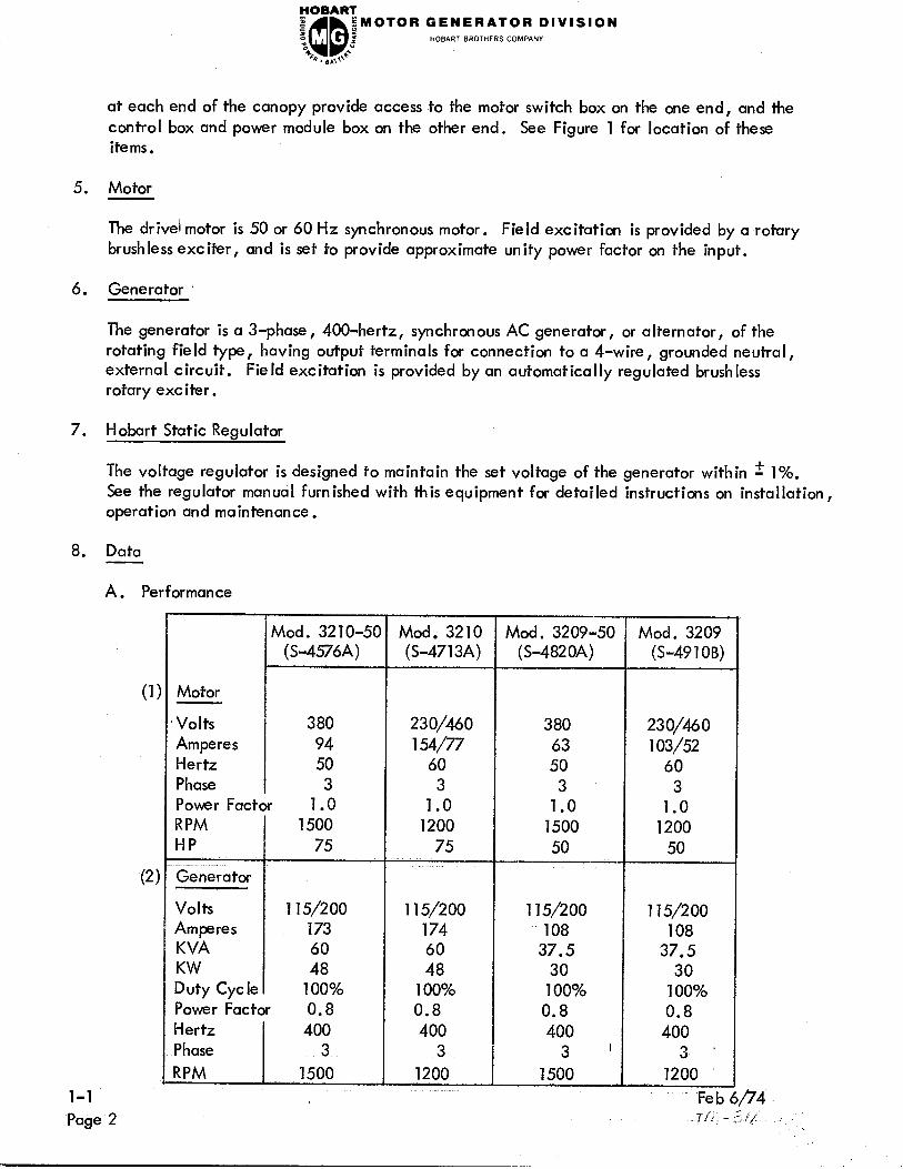
at each end of the canopy provide access to the motor switch box on the one end, and the
control box and power module box on the other end. See Figure 1 for location of these
items .
5. Motor
The drivel motor is 50 or 60 Hz synchronous motor. Field excitation is provided by a rotary
brush less exciter, and is set to provide approximate unity power factor on the input.
6. Generator
The generator is a 3-phase, 4000hertz, synchronous AC generator, or alternator, of the
rotating field type, having output terminals for connection to a 4-wire, grounded neutral,
external circuit. Fie Id excitation is provided by an automatically regulated brush less
rotary exe iter .
7. Hobart Static Regulator
The voltage regulator is designed to maintain the set voltage of the generator within f 1%.
See the regulator manual furnished with this equipment for detailed instructions on installation,
operation and maintenance.
8. Data
A. Performance
(2
Motor
Volts
Amperes
Hertz
Phase
Power Factor 1 .O
RPM 1500
HP 75
Generator
Volts 115/200
Amperes 173
KVA 60
Duty Cycle 100%
Power Factor 0.8
Mod. 32 1 O-50
(S-4576A)
380
94
50
3
Mod. 3210
(S-4713A)
230/460
154/77
60
3
1.0
1200
75
115/200
174
60
48
100%
0.8
400
3
1200
Mod. 3209-50
(S-4820A)
380
63
50
3
1.0
1500
50
115/200
108
37.5
30
100%
0.8
400
3 ’
1500
Mod. 3209
(S-4910B)
230/460
103/52
60
3
1.0
1200
50
115/200
108
37.5
30
100%
0.8
400
3 ’
1200
Fe b 6/74

GENERATOR DIVISION HOBART BROTHERS COMPANY
B. Dimensions
Stationary Unit Trailer Mounted’Unit- (Var; -*)
(1) Length - overall 97 inches (2464 mm) 107 inches (2718 mm)
I Width 40 inches (1016 mm) 62 inches (1575 mm)
He ight - overal I 54 inches (1372 mm) 67 inches (1702 mm)
Weight
(2) Trailer (Var. *)
Tread 56 inches (1422 mm)
Whee I base 82-l/4 inches (2089 mm)
Ground clearance 5-l/2 inches (140 mm)
Tires 6.00x9
Tire pressure 60 PSI (4.22 kg/sq‘cm)
* See Section 1-3, page 2, para. 3.
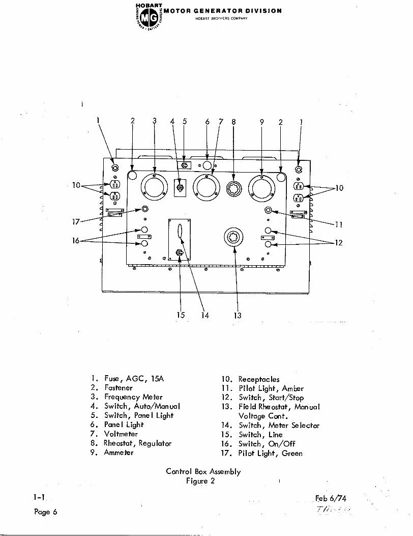
9. Control Box Assembly
A. General
The Control Box (Figure 2) is a sheet metal enclosure which houses and provides
mounting facilities for generator controls and monitoring instruments. The box
is mounted above the power module box at the generator end of the machine.
Canopy doors open to gain access to the instrument panel on the front of the
control box. The instrument panel is hinged and may be swung down to provide
access to the interior panel (Figure 3) which is mounted inside the control box.
B. Controls and Instruments See Figure 2
(1) Generator ON/OFF Pushbuttons (16) - Operating these buttons applies
or removes the load from the unit. A pilot light, adjacent to the push-
buttons, glows GREEN when power is available at the output terminals.
(2) Motor START/STOP Pushbuttons (12) - Momentary contact switches for
operation of the motor starter. An amber pilot light (11) indicates when
the starter is closed.
(3) Meter Switches (14) - The meter selector switch, used in conjunction with
the associated line selector toggle switch (15), enables the operator to read
generator output voltage and amperage in each phase separately. Voltage
may be read between any two phases or between any phase and neutral.
Amperage may be read in phase A, B or C, as desired.
l-l
Page 3

rOBART_
e
QD
gMOTOR GENERATOR DIVISION B :
z HOBART BROTHERS COMPANY “c
b. sa+e
400 Hz AC Generator with Canopy Closed
3 4 5 6 7
8
10
1. Motor switch box 6. Voltage regulator box
2. Synchronous motor 7. Control box
3. Drip-tight panel 8. Canopy
4. Access doors 9. Power module box
5. Generator 10. Frame
400 Hz AC Generator with Canopy Open
Figure 1 I
l-l Feb 6/74
Page 4 -tr-c p;

FOBART
: ;MOTOR GENERATOR DIVISION ‘: “0 QD =i HOBART BROTHERS COMPANY
% z .9. ,q,1” (4)
(5)
I
(6)
(7)
(8)
(9)
(10)
(11)
(12)
Regulator Rheostat (8) - The voltage regulator rheostat increases or decreases
the automatically regulated output voltage value.
Panel Light Switch (5) - Th is switch is to the left of the panel light (6) (at
the top of the panel) and turns the pane I illuminating light ON or OFF as
desired.
Automatic-Manual Switch (4) - When in AUTO position, the voltage is
automatically regulated. In MANUAL position, voltage is manually regulated
with the manual (field) rheostat. The latter is an emergency procedure only.
This switch is located between the frequency meter and the voltmeter.
120-Volt Receptacles (10) - These receptacles supply 115 volts, 400 hertz AC
for the operation of 400 hertz power tools or any resistive load not exceeding
15 amperes. Each receptacle is protected by a fuse.
Field Rheostat (13) - Th e output voltage of the unit can be adjusted
manually with this field rheostat when the automatic-manual toggle switch
is in MANUAL position, This is an emergency procedure for use in event of
regulator failure.
Ammeter (9) - Th e ammeter is located in the upper right-hand corner of the
generator control pane I. The purpose of the ammeter is to measure the
amount of current in the line selected by the meter switch, being supplied
by the unit. It will register only when current is being delivered.
Voltmeter (7) - The voltmeter is located in the upper center of the generator
control pane I. The purpose of the voltmeter is to register the voltage generated
by the unit. The voltage may be read directly on the meter by setting the
meter switch in the desired position.
Frequency Meter (3) - The frequency meter is in the upper left-hand corner
of the generator control cabinet, and is calibrated in hertz from 380 to 420.
The meter should indicate exactly 400 hertz at any load when input
frequency is 50 hertz.
Remote Control Terminal Strips - Terminal strips are provided in the enclosure
immediately above the motor and generator for connecting remote control
stations. (Not Shown. See Connection Diagram.)
10. Interior Pane I Assembly
A. General
The interior panel assembly is mounted vertically inside the control box, in back
of the instrument pane I. Components are described as follows. I
Feb 6/74 l-l
Page 5
FOBART
e s QD
iMOTOR GENERATOR DIVISION
d HOBART BROTHERS COMPANY %
4F,. s,,l’*’
1. 3 45 6 7 8 9 2 1
k 53 0
10 II0
16
t-:
1. Fuse, AGC, 15A 10. Receptacles 2. Fastener 11. Pilot Light, Amber 3. Frequency Meter 12. Switch, Start/Stop
4. Switch, Auto/Manual 13. Field Rheostat, Manual 5. Switch, Pane I Light Voltage Cont. 6. Panel Light 14. Switch, Meter Selector
7. Voltmeter 15. Switch, Line 8. Rheostat, Regulator 16. Switch, On/Off 9. Ammeter 17. Pilot Light, Green
,lO
,ll
.12
l-l
Page 6
Control Box Assembly
Figure 2 I

rOBART_
I z QD
:MOTOR GENERATOR DIVISION :
“0 E HOBART BROTHERS COMPANY
48 6 9. 8.0 B. Controls and Instruments
(1)
, (2)
(3)
(4)
(5)
(6)
(7)
(8)
(9)
Rectifier, Load Contactor (10) - Furnishes direct current to the operating
coil of the load contactor.
Relay, Time De lay (11) (hdervoltage Timer) - This relay is set for a 5-second
time delay in the undervoltage circuit. This relay provides time de lay when
abnormal loads are encountered for a short period of time. If an undervoltage
persists for a period longer than 5 seconds, the main contactor circuit will be
opened.
Manual Range Limiting Resistor (6) - This 250-ohm resistor is set to limit
voltage when the AUTO-MAN UAL Switch is in MAN UAL position, and the
manual rheostat is turned all the way clockwise.
Undervoltage Relay (2) - This relay is set to close its set of contacts when
the line-to-neutral voltage falls to 93-103 volts; this is equivalent to a
line-to-line output voltage of 161-178.5 volts. The closing of these contacts
energize a 5-seccnd time delay relay switch Gee (2) above], which in turn
opens the main contactor, protecting the load from effects of low voltage.
hderfrequency Relay (4) - Th ese contacts open if the frequency drops to
approximately 360 hertz and ret lose when the frequency recovers to 375 hertz.
The purpose of this relay is to open the main contactor and protect the load
from the effects of operating at too low a frequency.
Overvoltage Relay (1) - Th is relay has a normally closed set of contacts
which open if the voltage exceeds 130 to 134 volts, line-to-neutral, or
225 to 232 volts, I ine-to-l ine . This opens the main contactor to remove the
load from the generator.
Plug Interlock Relay (13) - The 28 volts DC from the aircraft, through
terminals E and F and Neutral causes the interlock relay to close, as well
as the contactor in the aircraft. With the interlock relay closed, power is
maintained to the rectifier, holding the contactor closed when the ON button
is released.
Plug Interlock Switch (or Test Bank Switch) (12) - This toggle switch should be
OFF when feeding an aircraft with control leads on E and F, or ON for feeding
a load bank or other non-aircraft load without the plug interlock system.
Current Limiting Resistor (3) - This 1000ohm, 250watt resistor is in series
with the plug interlock relay to limit the amount of load current drawn through
the plug interlock relay contacts, in case phase “C” of the load contactor
does not close when the generator “ON ” pushbutton is actuated.
I
l-l
Page 7

YOBART
e QQ EMOTOR GENERATOR DIVISION
s : z HOBART BROTHERS COMPANY
3
b . n ,,+**
2 3 4 5 6 7
I I
I t 0
I t I A
13 9 12
I r II IO 9 8
J
1. Overvoltage Relay
2. Undervoltage Relay
3. Resistor, 100 Ohm 25 W
4. Underfrequency Relay
5. Overload Relay
6. Resistor, 250 Ohm 100 W (Gen . Ext. Field)
7. Resistor, 50 Ohm 100 W (Overload Adjust)
8. Rectifier, Generator Exciter Field
9. Terminal Strips
10. Rectifier, Load Contactor
11. Undervoltage Timer
12. Test Bank Switch
13. Interlock Relay
l-l
Page 8
Interior Panel Assembly
Figure 3

FOBART
e QQ ;MOTOR GENERATOR DIVISION
I z e HOBART BROTHERS COMPAN”
“0
s. B,,+a
(10)
(11) I
Overload Relay (OL) (5) - This thermally operated relay serves to protect the
generator set from the effects of any induced overload (grounding or shorting
of exciter or generator, or exce,ssive load).
Overload Adjustment Resistor (7) - This resistor, connected in parallel with
the overload relay, serves to regulate the tripping time of the overload relay.
It is set to trip the overload relay at 25% overload in 4-5 minutes. If nuisance
overload tripping becomes a problem, trip point may be increased by moving
the resistor adjusting slide away from the end to which the jumper wire is
attached.
11. Motor Switch Box Assembly
A. General
The motor switch furnishes primary control for the drive motor. It is located in the
motor end of the canopy, with doors opening to gain access to the motor switch box.
N OTE : The motor STOP/START pushbutton switch is located on the control
panel at the opposite end of the unit. The non-manual components
for stop/start, time delay, voltage changeover, etc., are located
on a panel in the motor switch box assembly.
B. Components
(1)
(2)
(3)
Transformer - This transformer (3) reduces input line voltage from 380-V AC to
115-V AC for operation of the time delay relays, motor switch coils, control
relay, etc.
A 5-ampere fuse (15) protects the 115-V AC control circuit. The transformer
is functional at all times when input power is connected to the input terminals
and the overload relay (4) contacts are closed.
?TP%
- The control relay (9) applies power to the “main” motor switch
COI w en t e START pushbutton is pressed. The relay also by-passes the START and STOP pushbutton switches to prevent the relatively high switch-coil
currents from passing through them. All power for operation of switches, timers,
etc., must pass through this relay.
Main Motor Switch - The “main” switch (6) consists of three pairs of stationary
contacts and three pairs of movable contacts. Movable contacts are clamp
mounted on a bearing supported shaft. A core is attached to the shaft, so that
when the magnetic switch coil is energized,
the center of the coil.
it attracts the core and pulls it into
to close the contacts.
The core is thus moved to rotate the shaft sufficiently
The contacts are held in the closed position as long as
the switch coil is energized. When the coil circui,t is broken, the contacts
l-l
Page 9

FOBART D ; n “0 QQ
;MOTOR GENERATOR DIVISION :
2 HOBART BROTHERS COMPANY
B , B ,,J
ll
1. Time delay relay (5 seconds) 9. Control relay
2. Time delay relay (25 seconds) 10. Interlock bar
3. Transformer 11. Motor start switch
4. Overload relay 12. Field rectifier
5. Overload coil 13. Motor run switch
6. Main motor switch 14. Resistor
7. Changeover links 15. Fuse (5 A)
8. Terminal board
1-l
Page 10
Motor Switch Panel
Figure 4
Assembly I
Feb $74
T/i,/ .,‘/;
-6
IVISION FOBART e ,QQ
EMOTOR GENERATOR D z 2 HOBART BROTHERS COMPANY 3 2 4 0. B&l> ‘a
are opened immediately by gravity and spring loading. Stationary contacts
are equipped with blowout coils and arc shields to “blowout”, “dampen”,
and minimize arcing which results from opening the contacts. A small set
of contacts mounted on the “main ” contact shaft are closed when the “main ”
contacts are closed. These contacts apply a holding current to the switch
I coil circuitry and allow the START switch button to be released after the
main switch closes.
(4) Motor “Start” Switch - The motor “start” switch (11) is very similar to the
“main” motor switch (6) described above. Mechanical and electrical operating
characteristics are the same. The “start” switch is energized to close at the
same time the “main” switch is closed to provide a “wye” starting connection
to the motor‘stator windings.
(5) Time Delay Relay (25 Second) - This is a double-pole, double-throw,
120-V AC relay (2). It has an adjustable time delay range of from 5 seccnds
to 50 seconds. For this application it is adjusted for a time delay of 25 seconds
between energization of the coil and actuation of the contacts. The coil is
energized as soon as the control relay (9) contacts close. After a delay of
25 seconds, the time delay relay functions to open the “start” switch (11)
and close the “run” switch (13). At the same time it supplies power to the
5-second time delay relay (1) and also supplies 115-V AC power to the
voltage regulator for flashing the generator field. The 25-second delay
allows the motor to reach operating speed.
(6) Time De lay Re lay (5 Seconds) - This re lay (1) is identical to the time delay
relay (2) described above , except it is adjusted for a 5-second time delay.
It is energized at the same time the “run” switch is closed. The function
of this relay is to connect 115-V AC to the field application relay and
disconnect flashing current from the generator field, 5 seconds after the
“run” switch closes.
(7) Motor Run Switch - The motor “run” switch is identical to the “start” switch.
After the motor reaches operating speed with the stator windings in “wye”
connection, the “start” switch opens and the “run” switch closes to connect
the motor stator windings in “delta” connection for synchronous running.
The “main” switch remains closed during this operation.
(8) Start-Run Interlock Bar - The interlock bar is designed to mechanically pre-
vent the motor “start” switch and “run” switch from closing or being closed at
the same time.
(9) Field Rectifier - This rectifier converts 115-V alternating current to direct
current for excitation of the motor exciter fields. The rectifier becomes
functional five seconds after the motor run switch is closed.
I
Feb 6/74 l-l
71,; -5 : [; Page 11

(10)
(11)
(12)
(13)
(14)
FOBARZ z QQ
$MOTOR GENERATOR DIVISION s 2
z HOBART BROTHERS COMPANY “0
B . B ,‘,++
Overload Relay - These solenoid operated, dashpot type relays (4) protect the
motor against overload. Under a continuous overload condition, the coils
(5), which carry the motor input current, provide a magnetic force sufficiently
strong to pull the dashpot plunger upward against the retaining force of the
dashpot piston to OPEN the relay contacts which supply input power to the
trsformer (3). Thus, all operating power is removed from the controls and
all normally open switches return to OPEN position.
The resistive force of the dashpot on the movement of the plunger prevents
nuisance tripping of the relay contacts when the motor is overloaded for short
periods of time, such as in starting, etc.
Overload Coil - These coils (5), which are connected in series with input power
cables, provide magnetic force for operating the overload plungers.
Changeover Links - The connector links (7) provide a means of quickly changing
the motor stator connections for other applications.
Terminal Board - Four terminal boards (8) provide connection facilities for
electrical components interconnecting wiring.
Resistor - This 250-ohm, loo-watt resistor (14) functions to discharge voltage
induced in the revolving fields when the motor starts.
12. Power Module Assembly
A.
B.
l-l
Page 12
Genera I
The power module assembly provides a terminal point for the output power terminals,
and input power junction box. It supports the following components as described
below.
Components
(1)
(2)
(3)
Current Transformers (Ammeter) (7) - These transformers are used together with
the ammeter to indicate the amount of load current at any time.
Current Transformers (Line Drop Compensation) (9) - These transformers are
used with the regulator for line drop compensation.
Load Contactor (8) - The contactor connects and disconnects the generator
and the load. The contactor is furnished DC voltage by the rectifier on the
inter ior pane I . The generator ON/OFF switch (item 16, Figure 2) on the
control pane I, controls the opening and closing of the contactor.
Fed 6/74

YOBARI e a QQ
;MOTOR GENERATOR DIVISION ,,oB,WT BROTHERS COMPANY
z I CI
b . @ ,,k-
3 4 5 6 7
1. Studfiameplate “F” 6. Output Terminal~ameplate “N ”
2. Stud/hJameplate “E” 7. Current Transformers (Ammeter)
3. Output Terminalbameplate “C” 8. Contactor
4. Output TerminaI/t\lameplcite “B” 9. Current Transformer (Line Drop
5. Output Terminalfiameplate “A” C om-pensation)
Power Module Assembly
Figure 5 I
1-l
Page 13

FOBART @ QQ
2MOTOR GENERATOR DIVISION z 2
2 HOBART BROTHERS COMPANY “0
b . I ,,+*
(4) Output Power Terminals: Phase “A” (6)
Phase “B” (5)
Phase “C” (4)
Neutral “N” (3)
Stud “F” (2)
Stud “E ” (1)
l-l Feb 6p4
Page 14 . -: ,/ -,.;,* :

FOBART e QQ
;MOTOR GENERATOR DIVISION z s
z HOBART BROTHERS COMPANY “0
% . B ,,+”
SECTION 2. PREPARATION FOR USE
1. Genera I
When installing or storing this ground power unit, avoid locations exposed to high
huTidity or dust. Moisture condenses on generator parts and electrical controls, caus-
ing corrosion which can seriously affect operation and efficiency. Dust and dirt cause
needless extra wear on al I moving parts.
2. Wiring
The incoming power must be 3=phase, and should pass through a fused disconnect switch
ahead of the motor switch input terminals. Make certain that overload coils, motor
switch link position, and control transformer connections are correct for the input
voltage used.
Be sure that the power supply is the proper voltage (see nameplate), and that wiring
is of sufficient size to carry the load. Refer to the following data, which has been taken
from the National E lectrical Code.
Fuse and Wire Sizes
Chart 1
3. Motor Switch Overload Coils
When the unit is shipped, the motor switch is assembled with overload relay coils for
the voltage specified by the customer.
Overload Relay Coil Sizes
Chart 2
l-2
Page 1
FOBART I QQ
;MOTOR GENERATOR DIVISION f z
z HOBART BROTHERS COMPANY “0
B . B ,+”
CAUTION: IF A 3-CONDUCTOR, RUBBER-COVERED, INPUT POWER CABLE
IS USED, IT IS NECESSARY TO GROUND THE EQUIPMENT WITH
A WIRE OF MINIMAL COMPARATIVE SIZE TO THE WIRE- IN THE
INPUT POWER CABLE. THIS WIRE MAY BE BARE OR INSULATED
AND OF ANY COLOR, BUT IT MUST MAKE GOOD ELECTRICAL
I CONTACT WITH A METALLIC PART OF THE GENERATOR FRAME,
OF THE SHEET METAL CABINET, OR OF THE CONTROL BOX AND
A WATER PIPE OR THE FUSED DISCONNECT SWITCH BOX.
WHEN 4-CONDUCTOR, RUBBER-COVERED CABLE IS USED, THE
GROUNDING WIRE MUST BE GREEN IN COLOR. WHEN FLEXIBLE
ARMORED CABLE OR CONDUIT IS REQUIRED BY LOCAL CODES,
INSTALL IT IN SUCH A MANNER THAT ADEQUATE GROUNDING
OF THE EQUIPMENT IS INSmED.
WITH THE MACHINE FRAME GROMDED, THE OPERATOR IS
ALWAYS ASSURED MAXIMUM PROTECTION EVEN IN THE UN-
LIKELY EVENT OF INSULATION FAILURE OR ACCIDENTAL
GROUNDING OF THE POWER SUPPLY.
4. Mounting Installation of Synchronous Motor-Driven Generator Sets
A. General
No “hard and fast” rules for mounting the generator set can be given because
they may vary, depending upon the users requirements and facilities. Common
sense must be used in all installations to achieve a firm mounting which is free
from vibration and which does not place undue stress on the skid (mounting frame)
and motor-generator.
B. Mounting Cautions
Before recommending how to mount the generator set, we believe you should
first be cautioned about how NOT to mount it.
CAUTION: (l)DO NOT BOLT THE MACHINE TO AN U\IEVEN FLOOR,
PAD, OR PEDESTAL. THIS CAN CAUSE DAMAGING
STRESSES IN THE FRAME AND MOTOR-GENERATOR.
(2)D0 NOT SET (AND OPERATE) THE MACHINE LOOSELY ON
AN UNEVEN SURFACE. THIS CAN RESULT IN AN UN-
STABLE THREE-POINT SUSPENSION AND CAUSE VIBRATION.
Most all cases of vibration are caused by mounting the generator set on an uneven
floor surface.
I
l-2 Feb 6/74
Page 2 ,7;l’j .3 “2

$iOBARl z a QQ
qMOTOR GENERATOR DIVISION
‘c 2 HOBART BROTHERS COMPAN”
‘c, d 0. @*1x
C. Recommended Mounting Instructions
(1) Mounting surface - The single most important thing in generator mounting
is the mounting surface. Whether the machine is mounted on a cement
floor, or on a pedestal, the mounting surface should be even and smooth
I so that the full length of the skid can contact the cement.
(2) Pad mounting - It is recommended that some type of insulating pad be used
between the skid and mounting surface in all installations.
Resilient pads placed between the skid and the floor may help to compensate
for slight unevenness in the mounting surface, and also insulate the skid
from-floor to reduce vibration . . Hobart pads No. 389945 can be used
with or without bolts from skid to floor.
(3) Leveling pads - An alternate method to the plain pad installation described
above is one involving the use of self-contained leveling mounts such
as “Unisorb Level-Rites” or equivalent. These mounts will compensate
for a greater degree of floor unevenness than plain insulating pads.
(4) Instructions for use of insulating pads - Whatever pad components are
selected, these rules should be observed.
Fe b 6/74
(a) Support the skid at six or eight evenly spaced points, along each
side of mounting frame. (See illustration below.)
(b) Avoid solid contact between skid and floor.
(c) Mount Lshaped b rackets along outside of frame to prevent unit
from “walking”.
D. Vibration Trouble Shooting
Because of the complex nature of vibration and resonance, it may be necessary
to change the type and location of mounts to achieve the best results on a
particular machine.
Pad 389945 8 Req ‘d
Pads equally spaced from ends of frame
l-2
Jan 29/?‘5 Revised Page 3

FOBART z QQ
;MOTOR GENERATOR DIVISION z 5 HOBART BROTHERS COMPANY
“ss. 2 64 c . BAT+
l-2
Page 4
Feb ~$74

FOBART e QQ
$MOTOR GENERATOR DIVISION z :
z HOBART BROTHERS COMPANY
“0
44@. g,,++*
SECTION 3, OPERATION
1. General
Determine that the machine is properly installed (see Section 1, sub-section 12, para.
11 2 and 3). Connect a 3-phase load to terminals N, A, B, C, E and F at the upper
left-hand side of the power module panel. E and Fare interlock leads for aircraft
service. Also see Section 2, sub-section 4, l-2, page 2.
A. Starting
To start the unit, place the motor circuit breaker, if so equipped, in ON position,
momentarily push the motor START button (12, Fig. 2) and release it. The armature
should rotate in the direction indicated by the arrow on the housing. If it does
not, wait until the motor is up to speed, stop the machine (see paragraph D below),
and reverse any two of the incoming power lines. This change will cause the
armature to rotate in the correct direction. Armature rotation should be in a
counterclockwise direction when the operator is facing the generator control
pane I, where the START-STOP push buttons are located.
With the motor running , the AMBER pilot light will glow. After the machine is up
to full speed, adjust the voltage regulator rheostat until the voltmeter indicates
120 volts line to neutral.
B. Applying Load
Press the generator ON button to apply the load. The GREEN pilot light will
glow when the generator output contactor is closed. The voltage regulator will
automatically maintain the set voltage.
The voltage between any two phases (A-B, B-C, C-A) or line to neutral can be
read directly on the voltmeter by setting the meter selector switch and associated
toggle switch to the desired position.
The current on any phase can be read directly on the ammeter by placing the
meter selector switch on the desired phase (A, B, or C).
C. To Disconnect Load
To stop the supply of current to the load, push the generator OFF pushbutton.
D. To Stop Motor
Disconnect generator load, if any, push the motor STOP pushbutton momentarily,
and release it.
I
l-3
Page 1

FOBART e QQ
;MOTOR GENERATOR DIVISION t 2 HOBART BROTHERS COMPANY
“0 2
b . B ,,,J-
2. Remote Control
Remote stations may be connected to the terminal strips above the motor and generator
housings in accordance with the connection diagram furnished with the equipment. When
adding remote control, note that it is necessary to remove the jumpers from the terminals
used in cknecting the remote station.
3. Variations
As stated in Section 1, Description, paragraph 3, l-l, page 1; when variations to the
basic specifications occur, information will be added at the end of the section in which
information would normally be located.
Variation numbers assigned to the different specs (S numbers) covered by this manual,
vary from one to the other. Each spec (S number) is listed below, with variations shown
as they apply to the particular spec number.
A. S-4576A:
(1) Var. 1 - not used
(2) Var. 2 - not used
(3) Var. 3 - 220-Volt Input Power
(a) Explanation - Motor switch designed for 220-volt rather than
380-volt input voltage.
(b) Data - Data listed in Section 1, l-1, page 2 is changed by
Var. 3 as follows:
Motor
Volts 220 v AC
Amperes 161 A
(c) Fuse and Wire Size Change:
Amps at 220 Volt Max Fuse Size Min Wire Size
161 A 350 A #4/o
(d) Motor Switch Overload Coil Change:
Volts Coil Size _Y
Piston Projection Above Dashpot
220 6 turns 1 9/16 inch p
l-3 Feb 6/74
Page 2 7-/j) 2, ;k

yOBAi?l 3 3 QQ
;MOTOR GENERATOR DIVISION
“0 d HOBART BROTHERS COMPANY
+F p’ 4. &t (4) Var. 4 - With Economy Trailer
This four-wheel trailer, with manual brake, 6.00 x 9 tires, has no
fenders and no springs. See Chapter 4, Section 2, 4-2, page 34 for
parts list and (exploded) view of trailer.
B! S-4713A:
(1) Var. 1 -not used
(2) Var. 2 - not used
(3) Var. 3 - With Economy Trailer
Same as Var. 4 above (S-4576A-Var. 4).
C. S-4820A:
(1) Var. 1 - not used
(2) Var. 2 - not used
(3) Var. 3 - 2200Volt Input Power
(a) Explanation - Motor switch designed for 220-volt rather than
380-volt input voltage.
(b) Data - Data listed in Section 1, l-l, page 2 is changed by
Var. 3 as follows:
Motor
Volts 220 V AC
Amperes 108A
(c) Fuse and Wire Size Change:
Amps at 220 Volt Max Fuse Size Min Wire Size
108A 225 A #2 .
(d) Motor Switch Overload Coil Change:
Volts 7 ~~~~~~~~
Coil Size Piston Projection Above Dashpot
220 6 turns 7/8 inch 1
I
l-3
Page 3

YOBARI
e s QQ
;MOTOR GENERATOR DIVISION
2 HOBART BROTHERS COMPAN” ‘c
B . B .+‘-’
(4) Var. 4 - With Economy Trailer
This four-wheel trailer, with manual brake, 6.00 x 9 tires, has no
fenders and no springs. See Chapter 4, Section 2, 4-2, page 34
for parts list and (exploded) view of trailer.
D. S-4911 OB:
(1) Var. 1 - not used
(2) Var. 2 - not used
(3) Var. 3 - With Economy Trailer
Same as Var. 4 above, in S-4820A.
l-3
Page 4
Fe b 6/74

FOBART
B QQ ;MOTOR GENERATOR DIVISION
z z HOBART BROTHERS COMPANY
“0 2
B . B ,,++
CHAPTER 2. SERVICING
SECTION 1. MAINTENANCE. INSPECTION/ CHECK
1. Genera I
To make certain the generator set is always in good operating condition, it must be
inspected and maintained regularly and systematically.
2. Inspection, Testing and Repair
A. Motor Starting Switch
(1)
(2)
(3)
(4)
(5)
(6)
All three contacts in the switch should close at the same time. If they do not,
the stationary contact mount can be bent slightly to obtain simultaneous action
at all three poles.
If switch contacts are excessively pitted, burned, or worn, they should be
replaced.
The oil level in each of the two overload solenoid dashpots must be maintained
at the top of the three small, conical projections cn the upper side ‘of the piston,
or about 3/4 inch visible depth. Use Dow Corning #200 dashpot oil of 100
centistokes viscosity.
To check the dashpot oil level, remove the dashpot by forcing the heavy wire
retaining spring out of the groove on the under side of the dashpot and moving
it aside. The dashpot is then free to be removed from the assembly. Remove
the dust cover from the top of the cylinder. To remove the dust cover it is
usually necessary to pull up on the piston by grasping the projecting solenoid
core. Considerable force may be necessary to break the “suction” between
the piston and bottom of the cylinder.
Examine the faces of the movable and the stationary magnetic yokes to make
sure they are free from gum and dirt deposits.
Test the operation of the switch by pressing the START button. If the switch
does not operate, it may be due to a faulty overload relay or to a defective
NVR (no voltage release) coil. In either case the defective part should be
rep laced.
The switch coil winding should be tested for open circuits or shorted turns.
If an open circuit exists, it may be located at the connections between the
windings and the terminal lugs. If the open circuit cannot be found, or the
coil winding is shorted, the coil should be replaced. I
2-l
Page 1

FOBARI
I QQ :MOTOR GENERATOR DIVISION
z e HOBART BROTHERS COMPANY
“0 G
B . B ,, 16
(7) Inspect the NVR (no voltage release) coil. If the insulation is charred or burned
(an indication of shorted turns) the coil should be replaced.
(8) Inspect the overload relay molded block; if it is cracked or broken, it should be
replaced.
(9) If the relay contacts do not close when the RESET button is pushed, the complete
overload trip assembly should be replaced.
B. Lubrication
DO NOT LUBRICATE MOTOR OR GENERATOR BEARINGS. This generator is equipped
with sealed bearings which normally require no lubrication for the life of the bearings.
C. Periodic Inspection
N OTE: Check any change in operating noise or smoothness at once, and shut
unit down if change is abrupt and harsh. Sudden change of load or
operating conditions norma Ily indicates trouble requiring immediate
attention and remedial measures.
Routine inspection is as follows:
(1)
(2)
(3)
(4)
2-l
Page 2
Daily or 8 Hours - Observe operation of instruments (check voltage and current
in each phase at least daily).
Monthly or 100 Hours - Clean and visually inspect entire unit with unit stopped,
open access and pane I doors.. FOR SAFETY, OPEN DISCONNECT SWITCH
TO CUT OFF INPUT POWER. Check all electrical connections for security
.and correct placement.
Six Months or 500 Hours - With metal rod on housing, listen to bearing at
each end of rotor shaft for clicks, whines, or pounding, indicating trouble.
Send to overhaul if in doubt of serviceability of bearings.
Check rotating diodes and diode leads for tight, secure connections.
Clean complete unit with dry rags and low pressure air and inspect for broken
welds, deformation, cracks, or other evidence of damage. Check all attach-
ing hardware for adequate tightness and inspect all wiring for aged or frayed
insulation and for secure connections.
5000 Hours - This is the anticipated service life of the unit. Consider sending
to overhaul for rebuilding.

FOBART
e QQ -,MOTOR GENERATOR DIVISION
a 2 E HOBART BROTHERS COMPANY
“0
% . LI ,,+*
D. Inspection
After every 50 operating hours, inspect generator and control box for loose connec-
tions. Check instruments and switches for correct operation.
I
Fe b 6/74 __ )’ f’ T,y p ,.> ._.
2-l
Page 3

2-l
Page 4
YOBARI
e a QQ
;MOTOR GENERATOR DIVISION s
“0 E HOBART BROTHERS COMPANY
4 *. B,l\ 6
Feb6/?'4 _ .-, J (.I, " , 2'
HOBART e f QQ
iMOTOR GENERATOR DIVISION
i HOBART BROTHERS COMPANY
‘0
b . a ,,I’*+
CHAPTER 3. TROUBLE SHOOTING
SECTION 1. TROUBLE SHOOTING -PR.OCE-DURE.S
1. General
Trouble shooting is an orderly process of checking and eliminating possible causes of
trouble until the exact cause of a trouble is found. As a rule, the best place to start
looking for the cause of a trouble in a circuit is at the source of power. Continue
testing and checking the circuit, step-by-step, in an orderly manner, until the cause
of trouble is located. See connection and schematic diagrams.
2. Trouble Shooting Chart
A. Description
The trouble shooting chart lists information under three headings:
(1) Trouble, symptom, and condition
(2) Probable cause
(3) Test, check, and remedy
B. Use of the Trouble Shooting Chart
Read the trouble symptoms before proceeding to causes and remedies. For example,
at the beginning of the trouble shooting chart under MOTOR, first trouble listed
is: “Motor will not start - nothing happens when the start button is pressed”.
1 If the motor will not start, look to the right under PROBABLE CAUSE and REMEDY,
and find the various things which could cause the trouble, and what to do to check
and remedy them.
3. Equipment for Trouble Shooting
A good quality multi-scale voltohmmeter is the only instrument required for trouble
shooting. At least two “jumper” leads with “alligator”, or similar clips, will be
required.
4. Safety
WARN IN G: EXERCISE EXTREME CARE TO AVOID CONTACT WITH ELECTRICAL
CIRCUITS AND REVOLVING EQUIPMENT WHICH COULD CAUSE
SERIOUS INJURY IF TOUCHED WHEN TROUBLE SHOOTING OR
OPERATING THE EQUIPMENT.
I
3-l
Page 1

FOBART
e a QQ
:MOTOR GENERATOR DIVISION
t 2 HOBART BROTHERS COMPANY
“, *. ,,d 5. Diagrams
A schematic diagram of the generator set is provided in this chapter (Chapter 3). This
diagram can be very helpful in trouble shooting. Components shown in this diagram are identified by an alpha-numeric symbol in a legend appearing on the diagram. In some cases, an pbbreviation of the item name appears at the location of the item in the
schematic layout to further aid in its identification. For example, the symbol K9
identifies the overvoltage relay in the legend, and shows OV as well as K9 in the
schematic. M2 identifies the voltmeter, and VM appears at the location in the
diagram, along with M2.
A connection diagram is also furnished in Chapter 3. It also can be very helpful in trouble shooting, parts rep.lacement, etc. Also see Motor Switch Diagram. The numbers
of these diagrams appear in the table below.
6. Connecticns and Wiring
Before condemning any electrical component, check all connections and wiring which
could affect its operation. In many instances a component may be non-functional simply
because it is not receiving power because of a loose connection or a poor ground. In
most cases throughout the trouble shooting chart, it will be assumed that connections
and wiring have been checked.

FOBARZ
t :: QQ
:MOTOR GENERATOR DIVISION :
“0 0’ HOBART BROTHERS COMPANY
+? * . ALTO ‘C
TRnl IRIF PRARARIF CA1 ICF RF AAFnV
Motor will not No power to the motor Check input lines and fuses. Check
start - nothing to insure that disconnect switch is
happens when turned on.
the START button
is pressed. Overloads are stuck open Clean or replace.
(dashpot type)
Control transformer is defec- Replace or reconnect.
tive or incorrectly connected
(shou Id provide 110 volts
on secondary)
NVR coil on motor switch
is defective.
Replace the defective coil.
Flexible copper braid from
movable contacts loose or
open
Tighten, if loose. Replace.
Fuse or over load Copper braids from movable Tighten, if loose. Replace if
opens when contacts loose and shorting necessary.
START button out
is pressed.
Power has single phased Check input power on all phases.
Rotating diodes (motor end) Replace defective units.
have failed
Motor stator or motor revolv- If motor stator is faulty, send to
ing fieldsshorted or grounded overhaul for replacement of stator.
If revolving fields are faulty, re-
move ground if grounded or replace
field(s) if shorted.
Motor beg ins No fluid in overload dash- Fill to top of projection cn piston
to start but stops pots with Dow Corning dashpot fluid. See
before getting up Chapter 2, Sect. 1, sub-section 2.
speed.
Feb 6/74
77)) -3/b
3-l
Page 3

HOBART
P QQ ;MOTOR GENERATOR DIVISION
i t z HOBART BROTHERS COMPANY
“c
%* . B ,,,8
TROUBLE PROBABLE CAUSE REMEDY
MO TOR (CON TIN UE D)
3. Motor begihs to Wrong overload coils. There Replace with the proper overload
start but stops before should be a 12-l/2 turn coil coil.
getting up speed. for 380-volt operation.
(Continued)
Auxiliary contact on motor Reform or replace the contacts.
switch does not make contact
In put power has single -phased Check input lines and fuses; correct
as needed.
Defective or incorrectly Replace or reconnect.
connected control transformer
4, Motor starts, but No DC excitation to motor Repair or replace as needed, after
lacks power and exciter fields due to: determining defective components
“bogs down ” under and cause of failure.
load. * a) Open adjusting resistor
b) Defective motor fie Id
exciter rectifier
c) Defective rotary exciter
diodes or armature windings
d) Motor field timer defective
(will not close contacts)
* This condition will likely
develop an underfrequency
and undervoltage which will
trip the UF or UV re lay,
thus shutting the unit down.
5. Synchronous motor No excitation to motor field See item above.
draws excessive cur-
rent from line: poor
power factor
I
3-l ce b 6/f4
Page 4
-. . -...~

HOBAR;
e QQ ,MOTOR GENERATOR DIVISION
:: : 2 HOBART BROTHERS COMPANY
“0 4i *. BL,J
TROUBLE PROBABLE CAUSE
GENERATOR EXCITER AND REGULATOR
REMEDY
1. Nolvoltmeter Faulty voltmeter Check, replace if required.
reading, normal
voltage into Faulty meter selector switch Check switch - repair or replace, as
contactor required,
Loose connection Repair.
Rotary exciter not building
up:
a) Loss of residual magnetism Remagnetize with separate DC source
(12 or 24 volts). Repair circuit or
b) Open in static regulator replace defective components.
starting circuit
\ c) Defective revolving
diodes (generator end)
Replace defective diode(s).
Open revolving fie Ids Repair or replace.
2. Voltage too high, Loose connection to Rl, R2, Resolder connection if at rheostat,
regulator rheostat or R3. (See schematic.) or tighten screw if at terminal strip.
will not control
3. Voltage too low, Defective regulator rheostat Replace.
regulator rheo-
stat will not Defective static regulator Repair or replace.
control
4. Voltage oscillates Defective damping circuit Adjust per regulator manual or repair
in ‘regulator as required.
5. Voltage drops as Too long output cable Shorten output cable.
load is applied
Line drop compensation Determine that line drop compensation
turned off or set too low is on, then adjust per regulator manua
instructions.
I
Fe b 6/74 3-l
Page 5

FOBART
e QQ :YOTOR GENERATOR DIVISION
z : HOBART BROTHERS COMPANY % 2
b . B ,,++
TROUBLE PROBABLE CAUSE REMEDY
GENERATOR
1. Overheatb Shorted stator Remove short circuit or replace
stator,
Loose connection
Overload
Improper ventilation
2. Unbalanced output Open or shorted phase
Tighten connection,
Remove over load,
Provide adequate ventilation.
Correct shorted or open circuit
condition.
Loose connection Tighten connection. Also see
Section 3 - OPERATION.
3. Poor wave form
4. High harmonics
5. High deviation
fat tor
Unbalanced load Balance load.
Poor power factor load Balance load.
Non-linear load (for example,
SCR or magnetic amplifier
load)
GENERATOR CONTROLS
1. Cannot close con- Open contactor coil circuit Check out circuit to determine
tactor (Hartman point of open circuit, and remedy
type) situation, as required.
Shorted output con tactor coil Replace coil.
Defective diode pane I Replace defective diode(s).
Underfrequency, undervoltage, Correct defect in power or replace
or overload tripped relay(s) as required to remedy the
situation. Press reset push button
on hinged panel to reset latching
relays.
I
3-l Feb 6/74
Page 6 7/// - 5g

noBART e z QQ
iMOTOR GENERATOR DIVISION
“0 d HOBART BROTHERS COMPANY
+-c *.BLlT 6
TROUBLE PROBABLE CAUSE REMEDY
GENERATOR CONTROLS (CONTINIJD)
2. Cob tactor
nuisance trips
Any of the protective relays Check operating voltage and
may be opening frequency; if okay, replace relay(s)
as required or repair circuitry. If
overload relay trips, remove overload
Transient surge of voltage If load is within generator rating,
it may help to adjust ballast resistors
in regulator. See regulator manual
for further instruction.
Overvoltage relay trips too Replace overvoltage relay with one
soon on transient surge less sensitive or readjust to higher
trip point.
3. Unbalanced out- Unbalanced load No trouble unless protective relay(s)
put (voltage , trip.
current, or both)
indication Defective meter switch Replace.
Bad contacts in contactor Make sure all contacts make contact
or replace.
EXTERNAL LOAD
1. Unbalanced load Break in output cable Repair cable.
Bad connection .Check and tighten cable connections
as required.
2. Contactor will Cable not plugged into air- Plug cable into aircraft.
not stay closed, craft
opens immediate Iy
Test bank switch OFF If using load bank, turn switch ON,
or if aircraft has no provision for
28-volt return on E and F, throw
switch ON, otherwise throw switch
OFF.
I
3-l
Page 7

TROUBLE PROBABLE CAUSE RE ME DY
EXTERNAL LOAD (CONTINUED)
2. ContactorJ will Test bank switch OFF If aircraft does have 28-volt return,
not stay closed, (Continued) check to see that it is reaching the
opens output cable. (Check for voltage
immediately at output terminals E and F.)
(Continued)
Contactor coil defective Replace the coil.
Contactor control circuit Check out circuit and remedy
defective defect(s) as required.
I
3-1 Feb 6/74
Page 8 T’ -.- - i

General
The Illustrated Parts List identifies, describes, and illustrates main assemblies, sub-
as emblies, s and detail parts of the 400-Hz, synchronous motor-driven generator sets,
manufactured by Motor Generator Division, Hobart Brothers Company, Troy, Ohio
45373. The generator sets are identified as Specification No. 4576A, Specification
Nol 4713A, Specification No. 4820A and Specification No. 491OB and variations.
2. Purpose
The purpose of the list is to provide parts identification and descriptive information
to maintenance and provisioning personnel for use in provisioning, requisitioning,:
purchasing and issuing of spare parts.
3. Arrangement
Chapter 4 is arranged as follows:
Section 1 - Introduction
Section 2 - Manufacturer’s Codes
Section 3 - Parts List
4. Explanation of Parts List
A, Contents
The parts list contains a breakdown of the equipment into assemblies, subassemblies)
, and detail parts. All parts of the equipment are listed except:
(1) Standard h 1
ar d ware items (attaching parts) such as nuts, screws, washers,:etc.,i
which are available commercially. I
(2) Bulk items such as wire, cable, sleeving, tubing, etc., which are also corn- I
merically available.
(3) Permanently attached parts which lose their identity by being welded, sbldered,
riveted, etc., to other parts, weldments, or assemblies. I
B. Parts List Form / I
This form is divided into five columns. Beginning at the left side of the form; and I proceeding to the right, columns are identified as follows: I I
I
SECTION 1. INTRODUCTION
L- --------“--_ .- Page 1 1 /
7,::: ,- - I, j ,

‘__
(1) “FIGURE-ITEM NO. ” Column
(2)
(3)
(4)
(5)
.I.. _ _-_-
43 ._ __, -.
P_ase_ 2 _ .- --_- -.
7/J,/ - f- J
This column lists the figure number of the illustration applicable to a particular
parts list and also identifies each part in the list by an item number. These
item numbers also appear on the illustration. Each item number on an illustra-
1
ion is connected to the part to which it pertains by a leader line. Thus the
igure and item numbering system ties the parts list to the illustration and vice
versa.
“PART NUMBER” Column
All part numbers appearing in this column are Hobart numbers. If a Hobart
number has not been assigned to a part, “NO NUMBER” will appear in the
column and a vendor number (size description for hardware) will be listed in
the N OMENC lATURE column.
“N OMENC LATURE ” Column
The item identifying name appears in this column. The indenture method is
used to indicate item relationship. Thus, components of an assembly are listed
directly below the assembly and indented one space. Sizes, ratings, or vendor
part numbers may also appear in this column.
“EFF” (Effectivity) Column
This column is used to indicate applicability of parts when two or more models
of equipment are covered by the parts list. Code letters are used to indicate
parts which are used only on a certain mode I, or models. Parts in this list
are coded as follows:
Uncoded parts are usable on all models.
Parts coded “A” are usable on Specs 4576A only.
Parts coded “B ” are usable on Specs 4576A, Var. 3 only.
Parts coded “C” are usable on Specs 4576A, Var. 4 only.
Parts coded “D” are usable on Specs 4713A only.
Parts coded ‘E” are usable on Specs 4713A, Var. 3 only.
Parts coded “F” are usable on Specs 4713A, Var. 4 only.
Parts coded “G” are usable on Specs 4820A only.
Parts coded “H ” are usable on Specs 482OA, Var. 3 only.
Parts coded “J ” are usable on S pets 482OA, Var. 4 only .
Parts coded “K” are usable on Specs 49108 only.
Parts coded “L” are usable on Specs 491OB, Var. 3 only.
“UN ITS PER ASSEMBLY” Column
This column indicates the quantity of parts required for an assembly or subassembly
in which the part appears. This column does not necessarily reflect the. total ’
used in the complete end item.
Ma-y 12/75
.’

TOR GENERATOR Dl HOBART BROTHERS COMPANY
VISION
SECTION 2. MANUFACTURER’S CODES
1. Explanation of Manufacturer’s (Vendor) Code List
The following list is a compilation of vendor codes with names and addresses for
su P
pliers of purchased parts listed in this publication. The codes are in accordance
with the Federal Supply Codes for Manufacturer’s Cataloging Handbook H4-1, and
are arranged in numerical order. Vendor codes are inserted in the nomenclature
column of the parts list directly following the item name and description. In case
a manufacturer does not have a vendor code, the full name of the manufacturer will
be listed in the nomenclature column.
CODE VENDOR ‘S NAME AND ADDRESS
00779 AMP Inc.
P. 0. Box 3608
Harrisburg, Pennsylvania 17105
01121 Allen-Bradley Company
1201 South 2nd Street
Milwaukee, Wisconsin 53204
02660 Amphenol Corporation
2801 S . 25th Avenue
Broadview, Illinois 60153
03743 Appleton E lectric Company
1713 W. Wellington Avenue
Chicago, Illinois 60657
04009 Arrow-Hart and Hegeman Electric Company
103 Hawthorne Street
Hartford, Connecticut 06106
04713 Motorola, Inc.
Semiconductor Products Division
Phoenix, Arizona 85008
14831 Magnetic Components Inc.
290 Fischer Street
Ccsta Mesa, California 92627
16053 Pepka Spring Company
810 S. Waugh
Kokomo, Indiana 46901
4-2
Page 1

CODE
24248
26992
27191
31356
44655
60038
60741
71400
71785
72765
4-2 ..~.
Page 2
rOBART
I x
QD
~MOTOR GENERATOR DIVISION
“c 2 HOBPlRT BROTHERS COMPANY 4i- d 4. BLl\
VEN DORIS NAME AND ADDRESS
South Chester Corporation
South Company Division
3rd and Governor Printz Blvd.
Lester, Pennsylvania 19113
Hamilton Watch Company
Columbia and West End Avenue
Lancaster, Pennsylvania 17604
Cutler-Hammer Inc.
Power Distribution and Control Division
4201 N. 27th Street
-Milwaukee, Wisconsin 53216
J-B-T Instruments, Inc.
424 Chapel Street
P. 0. Box 1818
New Haven, Connecticut 06508
Ohmite Manufacturing Company
3601 W. Howard Street
Skokie, Illinois 60076
Timken Roller Bearing Company
1835 Dueber Avenue SW
Canton, Ohio 44706
Triplett E lectrical Instruments Company
Harmon Road
B luffton, Ohio 45817
Bussmann Mfg. Division of
McGraw-Edison Co.
2536 W. University Street
St. Louis, Missouri 63017
Cinch-Jones Mfg. Company
1026 S . H Oman Avenue
Chicago, Illinois 60624
Drake Manufacturing Company
4626 N . Olcott Avenue
Harwood Heights, Illinois 60656
I
May 12/‘75

CODE VEN DOR ‘S NAME AND ADDRESS
73559 Carling Electric, Inc.
505 New Park Avenue
Hartford, Connecticut 06110
nib63
75376
76062
77342
79470
80368
81091
88223
88601
roBART
I
QD
;MOTOR GENERATOR DIVISION f :
G HOBART BROTHERS COMPANY z B . L1 o,*G
89873
May 12/‘75
Hartman E lectric Manufacturing Company
P. 0. Box 8
Mansfield, Ohio 44901
Kurz-Kasch Inc.
1421 S. Broadway
Dayton, Ohio 45401
Marlin-Rockwell Company
Division Thompson Ramo Wooldridge Inc.
1002 Chandler Street
Jamestown, New York 14701
American Machine & Foundry Company
Potter & Brumfield Division
1200 E . Broadway, P. 0. Box 522
Princeton , Indiana 47570
Western Rubber Company
620 E . Douglas
Goshen, Indiana 46526
Sylvania Electric Products Inc.
730 Third Avenue
New York, New York 10017
Pass & Seymour Inc.
Solvay Station
Syracuse, New York 13209
Jaymar Terminal Boards, Inc.
25-27 Brutus Street
Weedsport, New York 13166
Westinghouse Electric Corp.
Transformer Division
Sharpsville Avenue
Sharon, Pennsylvania 16146
Cortland Industries, Inc.
4545 W. Cortland Street
Chicago, Illinois 60618
4-2
Page 3

FOBART
I 5
QD
:MOTOR GENERATOR DIVISION :
“0 2 HOBART BROTHERS COMPANY 46 ‘, 4. @LO
CODE
90763
91929 ’
VENDOR ‘S NAME AND ADDRESS
United-Carr Inc.
4258 N . Cicero
Chicago, Illinois 60640
Honeywell Inc.
Building Controls & Components Group
Micro Switch Division
Freeport, Illinois 61032
93929
98403
G-V Controls Inc.
81 Okner Parkway
Livingston, New Jersey 07039
Agastat Division
Elastic Stop Nut Corporation
1027 Newark Avenue
Elizabeth, New Jersey 07207
98410 E.T.C. Inc.
990 E . 67th Street
Cleveland, Ohio 44103
The following numbers were added to update vendor’s code:
0223 1 Anchor Rubber Company
840 S . Patterson Blvd.
Dayton, Ohio 45402
14655 1 Cornell & Dubilier Electric Corp.
50 Paris Street
Newark, New Jersey 07101
58849 Syntron Company
1938 Black Street
Homer City, Pennsylvania 15748
81074 Holub Industries, Inc.
414 Hi-Center
Sycamore, Illinois 60178
89616 Un ited States Rubber Company
Consumer Industrial and Plastics Products Division
Mishawaka, Indiana 46544
I
4-2
Page. 4
T. /. ,,-.f”-.:
May 12/;75
Revised Aug 20/?‘5

1.
2.
GENERATOR DIVISION HOBART BROTHERS COMPANY
SECTION 3. PARTS LIST
Explanation of Parts List Arrangement
The parts list is arranged so that the illustration will appear on a left-hand page and
th7 applicable parts list will appear on the opposite right-hand page. Unless the list
is unusually long, the user will be able to look at the illustration and read the parts
list without turning a page.
Symbols and Abbreviations
The following is a list of symbols and abbreviations used in the parts list.
* -
A,orAMP -
AC -
AR -
DC -
Fig. -
hd. -
hex -
Hz -
I.D. -
IN -
KVA -
MFD -
No. -
NHA -
PRV -
PSI -
Ref -
SA - TM -
T-R -
V-
NOlE:
Item not illustrated
ampere
alternating current
as required
direct current
Figure
head
hexagon
Hertz (c yc les -per.-sec ond)
inside diameter
inch
kilovolt-ampere
microfarad
number
next higher assembly
peak reverse voltage
pounds per square inch
reference (the item has been listed previously)
sub-assembly
Technical Manual
transformer-rectifier
volt (when used as a prefix to a five-digit number, indicates
vendor code) ,
An item which does not reflect an index number is an assembly which
is not illustrated in its assembled state, or it is similar (right-hand,
left-hand, top, etc .) to an item which is illustrated.
I
May 12/75 4-3
Page 1

4-3
Page 2
FOBART
E t QD
gMOTOR GENERATOR DIVISION :
“0 2 HOBART BROTHERS COMPANY
4i a4 Q. B&l+
/ /’ / -. 1 1 i
Generator Set
Figure 1
May 12/75
7 ,’
-

FOBART
z ::
;MOTOR GENERATOR DIVISION HOBART BROTHERS COMPANY
“c QQ d 46 Q , B ,, B
FIGURE HOBART
ITEM NO. PART NO.
l- S-4576A
S -4576A ,V3 I S-4576A ,v4
S-4713A
S-4713A,V3
S-4713A,V4
S-4820A
S-482OA,V3
S-482OA,V4
S-4910B
S-491OB,V3
1 H F-2727
2 5oN H -787
3 No Number
4 No Number
N OME NC LATURE UN ITS
1234567 EFF A!?Y
GENERATOR SET MODE L NO. 3210-50
GENERATOR SET WITH 220 VOLT INPUT
GENERATOR SET (TRAILER MOUNTED)
GENERATOR SET MODEL NO. 3210
GENERATOR SET (TRA ILER MOUN TED)
GENERATOR SET WITH UNGROUNDED
NEUTRAL AND PHASE REVERSALRELAY
GENERATOR SET MODE L N 0. 3209-50
GENERATOR SET WITH 220 VOLT INPUT
GENERATOR SET (TRAILER MOUNTED)
GENERATOR SET MODE LNO. 3209
GENERATOR SET (TRAllER MOUNTED)
. EYE, LIFTING
. CANOPY ASSEMBLY (For details
see Fig. 2)
. MOTOR & GENERATOR GROUP
(WITHOUT CANOPY) (For details
see Fig. 3)
. MOUNTING FRAME &lkAlLER
GROUP (For details see Fig. 13)
A
B
C
D
E
F
G
H
J
K
L
1
1
1
1
May 12/?‘5
Page 3
-_---- _ FOBART
e z QQ ;MO?OR GENERATOR DIVISION
“0 : HOBPlRT BROTHERS COMPANY B. B,,l~G
4-3
Page 4
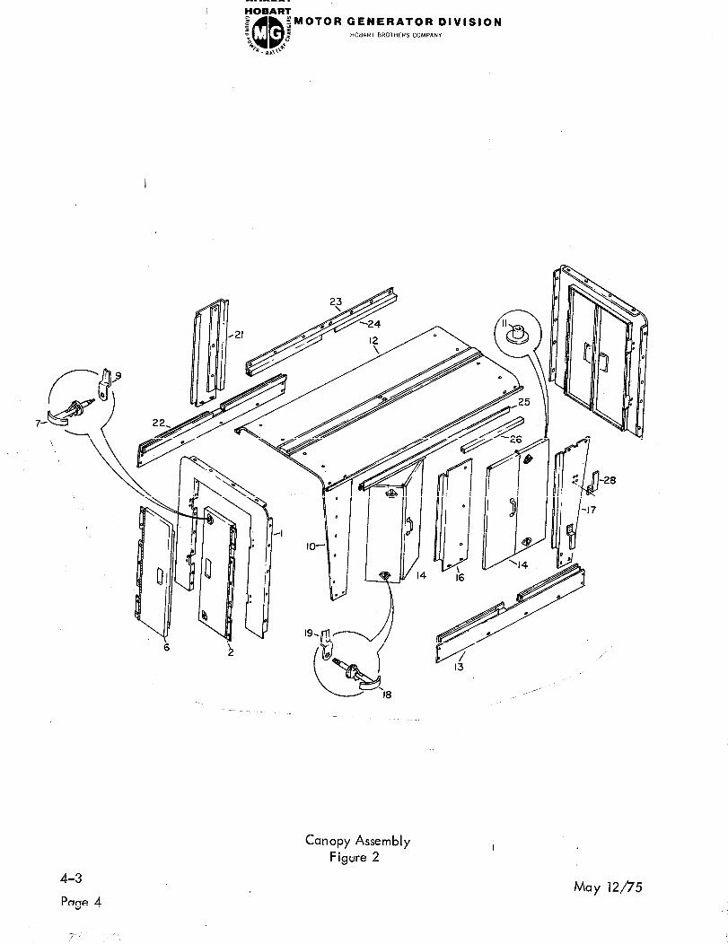
Canopy Assembly
Figure 2
May 12fl5

FOBART
z z QQ
qMOTOR GENERATOR DIVISION
d HOBART BROTHERS COMPANY “c b . B ,,,J
FIGURE PART
ITEM NO. NUMBER
2- 50N H -787
1
2
* 3 ’
* 4
* 5
6
7
* 8
9
10
11
12
13
14
* 15
16
17
18
19
* 20
21
22
23
24
25
26
* 27
28
* 29
Q 30
* 31
50N H -774
50N H -775
50N H -776
5JB-984
5JB-985
H F-584
5ON H -778
60FC -622
6OFC-620
60GH P-234
50N H -796
75GH -323
50NH -765
50NH-810
50N H -784
75N H -334
50N H -797
5ON H -786
1 OOGH -683
3DW-248
1 OOGH -685
50N H -800
50N H -807
50N H -790
50N H -79 1
50N H -792
50N H -793
5ON H -794
50N H -792
60GH-145
DWP-982
50N H -622
480366
402987
NOMENCLATURE
1234567
UN ITS
Per EFF ASSY
CANOPY ASSEMBLY (For NHA See
Fig. 1)
. PANEL, END, CANOPY SA
PANEL, END
: : DOOR, RIGHT, SA
. . CAM V24248, No. 17012-15
. . SPRING V24248, No. 17011-15
. . SPACER
. . DOOR, LEFT, SA
. . HANDLE, LATCH, SA
. . SPACER
. . LATCH, DOOR.
. PANEL, LEFT FRONT, & RIGHT REAR
. GUIDE, DOOR
. TOP, CANOPY, SA
. PANEL, SIDE, LEFT
. DOOR, FRONT & REAR, ASSEMBLY
. BLOCK, HINGE, DOOR
. PANEL, LEFT, CENTER, SA
. PANEL, LEFT, REAR, & RIGHT FRONT
. HANDLE, LATCH, SA
. LATCH, DOOR
. SPACER, DOOR LATCH
. PANEL, RIGHT, CENTER
. PANEL, SIDE, RIGHT
. TRACK, RIGHT, TOP, SA
. . ANGLE
. . TRACK
. TRACK, LEFT, TOP, SA
ANGLE
: : TRACK
. HOOK, DOOR, END, CANOPY
. HANGER, CABLE
. PLATE, RE IN FqR.C IN G, CABLE HAN GER
. STIFFENER, PAti.E L, CEN TER
. NAMEPLATE, HOBART
REF
2
1
1
4
4
4
1
2
2
2
2
8
1
1
4
8
1
2
8
8
8
1
1
1
1
2
1
1
2
4
4
4
2
2
I
May 12/f5 4-3
Page 5

FOBART
B QQ gMOTOR GENERATOR DIVISION
z 5 HOBART BROTHERS COMPANY “c 2 B . B ,&
Motor Generator Group Without Canopy l
Figure 3
4-3
Page 6
May 12/75
-r- 4 /f,, ”

FIGURE
ITEM NO.
3-
II
2 ,
3
4
8 * 9
YOBART e a QD
5MOTOR GENERATOR DIVISION :
% E HOBART BROTHERS COMPANY 4k 6 0. B,C
PART
NUMBER
No Number
3 8250 1-24
50NH -703-O
No Number
481063-l
481063-2
481051-l
481051-2
No Number
381090
481061-l
481061-2
481062
A-98
NOME NC IATURE
1234567
MOTOR GENERATOR GROUP WITHOUT
CANOPY (For NHA See Fig. 1)
. BOX ASSEMBLY, MOTOR SWITCH
(For Details See Fig. 4)
. PANE L ASSEMBLY, DR IPPROOF
(For Details See Fig. 6)
. MOTOR GE NERATOK GROUP
(For Details See Fig. 7)
BOX, CONTROL, REGULATOR 8,
’ POWER MODULE ASSEMBLY
BOX, CONTROL, REGULATOR &
’ POWER MODU lE ASSEMBLY
. . BOX ASSEMBLY, CONTROL (For
Details See Fig. 8)
. . BOX ASSEMBLY, CONTROL (For
Details See Fig. 8)
. . BOX GROUP, REGUIATOR (For
Details See Fig. 10)
. . SUPPORT, MOUNTING (For Details
See Fig. 13)
MODU LE ASSE MB LY, POWER
l ’ (For Details See Fig. 12)
. . MODULE ASSEMBLY, POWER
(Fcr Details See Fig. 12)
. . COVER, POWER MODULE
. NAMEPLATE, ARROW
UN ITS
EFF ElY
Ri F
1
HJKL 1
ABCDEF 1
HJKL 1
ABCDEF 1
1
1
HJKL 1
ABCDEF 1
1
1

HOBART % a QD
iMOTOR GENERATOR DIVISION 5 HOB/\RT BROTHERS COMPANY
8 2 *F l
*. BL,I+
13 /
Motor Switch Box Assembly
Figure 4 I
4-3
Page 8
May 12p5
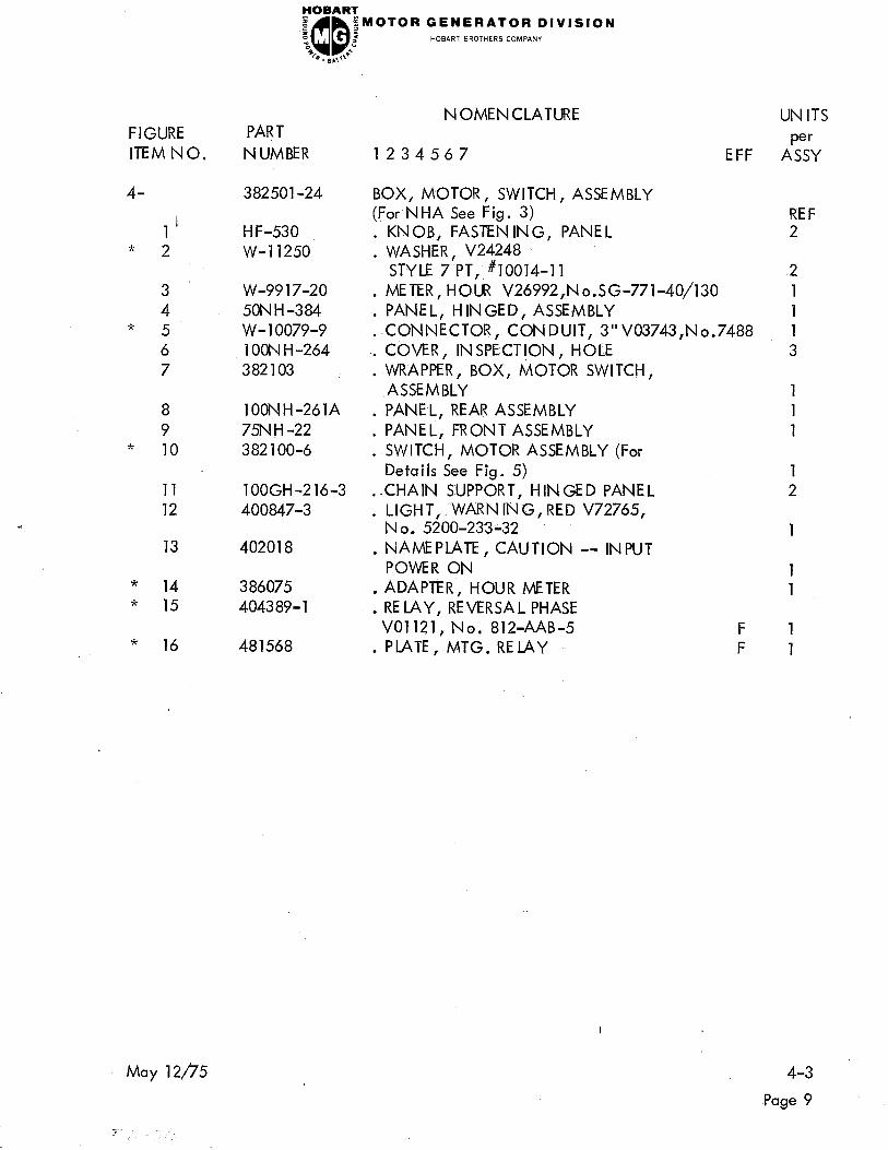
FIGURE PART
ITEM NO. NUMBER
4- 382501-24
l1 * 2
3 W-99 17-20
4 50NH-384 * 5 W-l 0079-9
6 1 OON H -264
7 382103
8 lOONH-261A
9 75N H -22 * 10 3 82 100-6
11
12
13
* 14 * 15
* 16 481568
YOBART
e :: QQ iMOTOR GENERATOR DIVISION
- “c 5 HOB.wT BROTHERS COMPANY 4i Q. BLIl ‘+
H F-530
W-l 1250
lOOGH-216-3
400847-3
402018
386075
404389-l
NOMENCLATURE
1234567 EFF
BOX, MOTOR, SWITCH, ASSEMBLY
(For NHA See Fig. 3)
. KNOB, FASTENING, PANEL
. WASHER, V24248
STYLE 7 PT, #10014-l 1
. METER, HOUR V26992,No.SG-771-40/130
. PANEL, HINGED, ASSEMBLY
. CONNECTOR, CONDUIT, 3”V03743,No.7488
. -COVER, IN SPECTION , HOLE
. WRAPPER, BOX, MOTOR SWITCH,
ASSEMBLY
. PANEL, REAR ASSEMBLY
. PANEL, FRONT ASSEMBLY
. SWITCH, MOTOR ASSEMBLY (For
Details See Fig. 5)
. CHAIN SUPPORT, HINGED PANEL
. LIGHT, WARN IN G., RED V72765, No, 5200-233-32
NAMEPLATE, CAUTION -- INPUT
’ POWER ON
ADAPTER, HOUR METER
: RELAY, REVERSAL PHASE
VO1121, No. 812-AAB-5
. PLATE, MTG. RELAY
F
F
UN ITS
Per ASSY
REF 2
2
1
1
1
3
1
1
1
1
2
1
1
1
1
1
May 12/75 4-3
Page 9

4-3
Page 10
FOBART
P QQ a $MOTOR GENERATOR DIVISION
; 2 HOBART BROTHERS COMPANY *F Q. 8AlY 6
I
Motor Switch Assembly
Figure 5 I
May 12/75
-,, :’

FIGURE HOBART
ITEM NO. PART NO.
5- 382100-d
1 404060-3
* 21 W -9350-76
3 40191 l-8
* 4 w-9350-77
5 ’ 40065 1
6 16DA-4252-4 * 7 w-9350-75
8 4OOMS-18 9 400670
10
11
12
13
14 * 15
16
17
18
19
20
21
22
23 * 2d
25
26
27
28 * 29
30
DATA #22 1 OA
50MS -28
4ooMS -11
FW-2131
4OOMS-16
6FW-574
2OOMS-146
1 OON M-97
1 OON M-98
4ooMS-10
lOOMS-122-l
200MS-132A
lOONM-94
lOOMS-21
1 OON M-95
w-799c-66
50MS -60
1 OON M-96
lOOMS-122-o
lOONM-92
lOOMS-132
1 OOMS -3 83
31
32
33
34
* 35
36
lOOMs-14
2OOMS-138
200MS -135A
400MS -72
w-9350-74
400MS -63
May 12p5
FOBART;
s a “c QD
;MOTOR GENERATOR DIVISION
i HOBART BROTHERS COMPANY
%. ,,,+*
N OMENC IATURE
1234567
UN ITS
EFF AttrY
SWITCH, MOTOR, ASSEMBLY REF.
. RE IAY, TIME DE LAY V98403,No.
7012ADA2M
. CABLE $182
. STRIP, TERMINALV88223, No. 441-8
. CABLE #181
FUSEHOLDER, WESTINGHOUSE
’ ADD-A-PART N 0.257A574GOl
. FUSE, MDL, 5 AMP V71400,No.MDL
CABLE, #180
: ARM, ROCKER
. TRANSFORMER V88601, Type MTA No.
332B635A22 Frame N o. 1730
COIL, NVR
: HOLDDOWN GOIL
BUS, LONG, RELAY TO CONTACTOR
: RELAY, OVER LOAD
COIL, OVERLOAD
: COIL, OVERLOAD
ACDEFGJ KL 3
BDEFHKL 3 WASHER, BLOWOUT COIL
: CYLINDER, COIL, BLOWOUT 6
3 INSULATOR, COIL, BLOWOUT
: BUS, SHORT, RELAY TO CONTACTOR
3
2
HOLDER, ARC SHIELD
: COIL BLOWOUT
9
3
S H IE LD , ARC ASSE MB LY
: . SIDE, SHIELD
‘3
2
BACK, SHIELD
: : SPRING V16053, No. 66 1
1
. . GUIDE, END (1 R.H. and 1 L.H.)
PLATE, SHIELD
l ;IOLDER ARC SHIELD
: CONTAdT
POST, CONTACT, STATIONARY
: MOUNT, DOUBiE, MOVABLE CON-
2
1
9
6
12
TACT, ASSEMBLY
CLAMP, SHAFT
: BEARING, SUPPORT, SHAFT
SHAFT, ARMATURE, MAGNETIC,
’ CONTACTOR
STRAP, CONNECTING, MOVABLE
l CONTACT
CABLE b34 & #185
: BUS, ANGLE I
3
14
1
1
6
2
9
4-3
Page 11

4-3
Page 12
FOBART I f QQ iMOTOR GENERATOR DIVISION
“0 E HOBARr BROTHERS COMPANY B. B,,++--
May 12/75

FOBART 0 %
pMOTOR GENERATOR DIVISION HOBART BROTHERS COMPANY
“0 QQ i % 4.,,,+++
FIGURE HOBART
ITEM NO. PART NO.
5- 37
3 7
39
40
41 t
* 42
43
44
45
46
47
48
* 49 * 50
51
52
53
54
55
56
57
58
59 60
61
62
63
64
65
66
67
68
May 12/f5
4oJ -90
400MS -58
363769-3
50MS -696
1 OOMS -36
w-9350-73
40191 l-5
200MS -145
2ooMS -143
400589-5
16DA-1626-4
200MS -140
60GH P-424
4OOMS -62
50MS -472
400MS -23A
4ooMS -19
4ooMS -17
363769-4
FW-3294B
4ooMS -9
lOOMS-358
1 OOMS -6
lOOMS-141
lOOMS-117
lOOMS-137
DATA-1330A
1 OOMS -349
404065- 1
1 OOMS -382
2OOMS -116
6FW-557A
NOMENCLATURE UN ITS
1234567 EFF A:&
LINK, CHANGEOVER
: BUS, JUMPER, CONTACTOR TO CHANGE-
OVER
. INSU lATOR, SHAFT
CONTACT, AUXILIARY, MOVABLE, ASSY
: CONTACT, AUXILIARY, STATIONARY,
ASSEMBLY
CABLE #185
: STRIP, TERMINALV88223, No. 441-5
STOP, MOVABLE, MAGNETIC YOKE
: YOKE, MAGNETIC, MOVABLE, ASSY
STRIP, TERMINAL V98410, No. 38012-
* 3820
REL4Y V77342, No. PR-2271-1
: YOKE, MAGNETIC STATIONARY
CLAMP, CABLE
: BRACKET, CABLE
. SUPPORT, SINGLE, BEARING
SHAFT, ARMATURE, LINE SWITCH
: SLEEVE, ROCKERARM
SUPPORT, ROCKER ARM
: INSULATCR, SHAFT
STRAP, CONNECTING MOVABLE CON-
’ TACT
. BUS, CONNECTING CONTACTOR
CYLINDER, COIL, BLOWOUT
: WASHER, COIL BLOWOUT
YOKE, MAGNETIC, MOVABLE ASSY
: STOP, MOVABiE, MAGNETIC YOKE
YOKE, MAGNETIC, STATIONARY,
’ ASSY
COIL, NVR
: BUS, STUD TO BLOWOUTCOIL
RECTIFIER, SILICON V04713,
’ No. SDA10270-1
MOUNT, SINGLE, MOVABLE CON-
* TACT ASSEMBLY
CONTACT
: COIL, BLOWOUT
I
6
3
2
1
1
1
1
1
1
2
2
1
2
4
6 1
6
12
2
2
2
2
3
1
6
12
6
4-3
Page 13
4-3
Page 14
GENERATOR DIVISION HOBART BROTHERS COMPANY
May 12/7’S

FIGURE HOBART
ITEM N 0. PART N 0.
5- 69 lOOMS-146
70 W-2974-F
71 400078
7? 400092
73 400097
74 400098
75 1 OOMS -79
* 76 W-9234- 145 * 77 W-9234-112 * 78 W-9760-4
* 79 W-9648-226
* 80 w-9350-75
May 12/?‘5
N OMENC LATURE
1234567
SHIELD, ARC
: RES ISTOR V44655, No. 09608
BRACKET, MTG., RES ISTOR
’ V44655, No. 12
. NAME PLATE, Ll
. NAMEPLATE, L2
NAMEPlATE, L3
: INSULATOR, CYLINDER, COIL
. CABLE, b4, 105, 106
. CABLE, #llO
CABLE, MOTOR STATOR
l EXTENSION
CABLE, GENERATOR STATOR
’ EXTENSION
. CABLE, #ill
UN ITS
EFF !%Y
6
1
12
12
ABCDEGHJ KL 1
I
4-3
Page 15

GENERATOR DIVISION HOwaT BROTHERS COMPANY
Drip-Proof Panel Assembly
Figure 6
4-3 May 12p5
Page 16
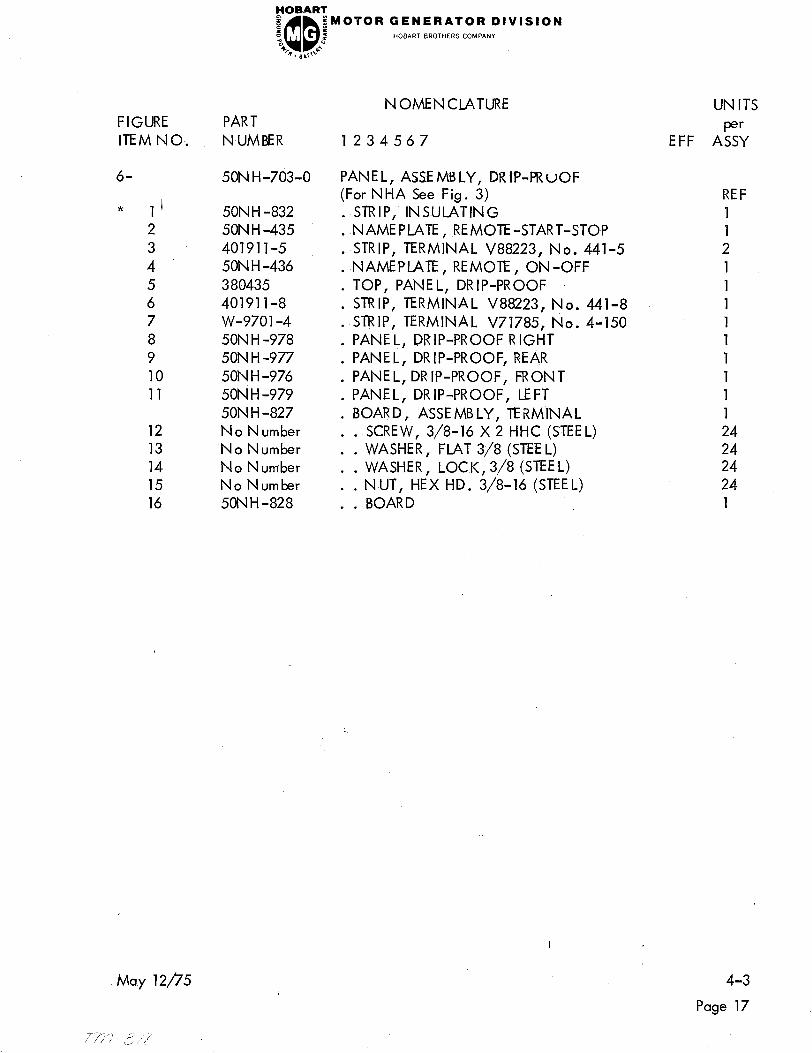
FIGURE PART
ITEM NO.. NUMBER
6- 50N H-703-0
* 1’
2
3
4 *
5
6
7
8
9
10
11
12
13
14
15
16
50N H -832
50N H -435
40191 l-5
50N H -436
3 80435
40191 l-8
w-9701 -4
50N H -978
50N H -977
50N H -976
50N H -979
50N H -827
No Number
No Number
No Number
No Number
50NH -828
May 12/?‘5
r/y,’ - ,3,, ,‘,’
GENERATOR DIVISION HOBART BROTHERS COMPANY
NOMENCLATURE
1234567
PANEL, ASSEMBLY, DRIP-PRuOF (For NHA See Fig. 3)
. STRIP, INSULATING
. NAMEPLATE, REMOTE-START-STOP
. STRIP, TERMINAL V88223, No. 441-5
. NAMEPLATE, REMOTE, ON-OFF
. TOP, PANEL, DRIP-PROOF
. STRIP, TERMINAL V88223, No. 441-8
. STRIP, TERMINAL V71785, No. 4-150
. PANE L, DRIP-PROOF RIGHT
. PANEL, DRIP-PROOF, REAR
. PANEL, DRIP-PROOF, FRONT
. PANEL, DRIP-PROOF, LEFT
. BOARD, ASSEMBLY, TERMINAL
. . SCREW, 3/8-16 X 2 HHC (STEEL)
. . WASHER, FLAT 3/8 (STEEL)
. . WASHER, LOCK, 3/8 (STEEL)
. . NUT, HEX HD. 3/8-16 (STEEL)
. . BOARD
I
UN ITS
EFF A!&
REF
1
1
2
1
1
1
1
1
1
1
1
1
24
24 24
24
1
4-3
Page 17


FIGURE
ITEM NO.
7-
1 ’
2
HOBART
PART NO.
N o. N umber
3
4
5
6
7
5CN H-130
3 80524-2
3 80527-2
380524- 1
380527- 1
381649-l
382432- 1
380376- 1
5ONH-1015-l
3 80943
5BJ -32
5BJ -32
5BJ -34
5BJ -33
5BJ-35
2CRT-352- 1
8
9
10
11
12,
2ORT-353- 1
3 80942
403982
13
14
15
16
17
18
19
20
* 21
W-10072-1
380526-2
3 80530-4
380526-l
3 80530- 1
5CNH-54
50NH-840
HF-879
DW-883
DW-882A
DATA-2033
50N H -43
5oN H -42
W-l 0079-3
May 12/75
Aug 20/75 Revised *
FOBART
8 x
QD
.gMOTOR GENERATOR DIVISION
,= HOBART BROTHERS COMPANY “c
b . B ,J
NOMENCLATURE
1234567
MOTOR-GENERATOR GROUP (For NHA
See Fig. 3)
. GUARD, FAN
. H OUS IN G & STATOR ASSY (MOTOR)
. HOUS ING & STATOR ASSY (MOTOR)
. HOUSING & STATOR ASSY (MOTOR)
HOUS IN G & STATOR ASSY
: ARMATURE ASSEMB LY
(MOTOR)
ARMATURE ASSE MB LY
: ARMATURE ASSEMB LY
. ARMATURE ASSEMBLY
EXCITER ASSEMBLY, BRUSHLESS
: : EXCITER ASSEMBLY, BRUSHLESS
EXCITER ASSEMBLY, BRUSHLESS
: : . BASE ASSEMBLY, MOUNTING
. . . PLATE, INSULATING
BAR, BUS, CONNECTING
’ : : DIODE, POS IT IVE
DIODES
. V58849,
N o. 92429-AF
. . . D IODE, NEGATIVE V58849,
N o . 92429-C F
. . . BRACKET, MOUNTING, MICRO
SWITCH
SWITCH, MICRO V91929,
’ l ‘No. BZ-2RD
. BEARING V76062, No. 310-SFFC
. CAP, BEARING
. HOUSING & STATOR ASSY (GENERATOR)
. HOUS IN G & STATOR ASSY (GENERATOR)
HOUS IN G & STATOR ASSY (GENERATOR)
: HOUSING & STATOR ASSY,(GENERATOR)
. COVER,, HOUSING, EXCITER
COVER, SCREEN
: WASHER, RETAINING, BEARING
. GASKET
. FELD
. INSULATION
. POLEPECE
CONNECTOR, BOX, STRAIGHT, 3/4,
l V03743, N o. 7289V (One required for
generator, two required for motor) (To
be used with flexible metallic electrical
conduit) I
. .,
‘., s_
UN ITS;
per ’
EFF pssy
REF. :
‘1
ABC :l
DEF 11
GHJ 1
KL ‘1
ABC 1
DEF 1
GHJ ,l
KL 1
ABCGHJ ,l
ABCGHJ 1
DEFKL ‘2
I1
1
2
3
3
ABCGHJ ‘2
ABCGHJ 2
2
‘2
ABC 1
DEF 1
GHJ 1
KL 1
2
2
2
2
2 SETS
8
8
,3 :
4-3 1
Page 19’

4-3
Page 20
FOBAR’t
B z
QD
;MOTOR GENERATOR DIVISION a HOBART BROTHERS COMPAN”
“0 2
b . LI ,,+**
May 12/75
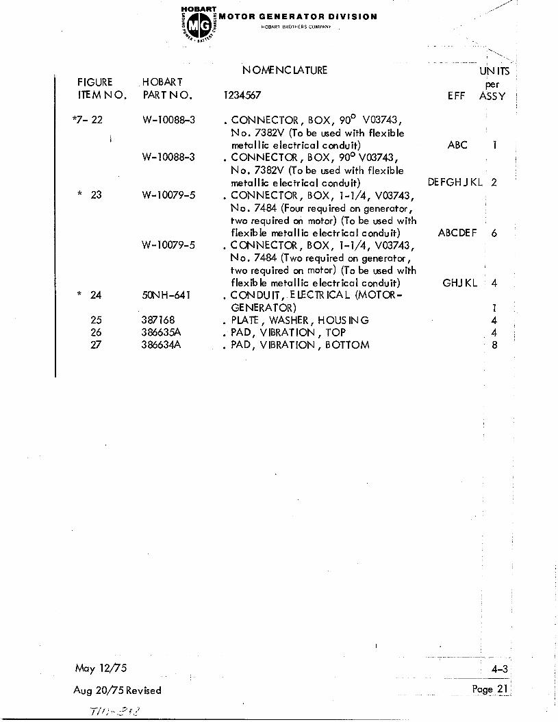
,** FOBART __ ‘-
I z
QD
iMOTOR GENERATOR DIVISION
“c I HOBART BROTHERS COMPANY
*c a’ Q. I,t+
FIGURE HOBART
ITEM NO. PART N 0.
*7- 22 W-10088-3
N OMENC LATURE
-.. “.., , . . . .
UN ITS ~
1234567 EFF AGrY ;
CONNECTOR, BOX, 90’ V03743,
’ No. 7382V (To be used with flexible
metallic electrical conduit)
CONNECTOR, BOX, 90’ V03743,
l No. 7382V (To be used with flexible
metallic electrical conduit)
I
W- 10088-3
* 23 w- 10079-5
w-10079-5
* 24 50NH-641
25 387168
26 386635A
27 386634A
May 12/?‘5
Aug 20/75 Revised
. CONNECTOR, BOX, l-1/4, V03743,
No. 7484 (Four required on generator,
two required on motor) (To be used with
flexible metallic electrical conduit)
CONNECTOR, BOX, l-1/4, V03743,
’ No. 7484 (T wo required on generator,
two required on motor) (To be used with
flexible metallic electrical conduit)
CONDUIT, ELECTRICAL (MOTOR-
* GENERATOR)
. PLATE, WASHER, HOUS IN G
‘PAD, VIBRATION, TOP
: PAD, VIBRATION, BOTTOM
ABC 7 /
DEFGHJKL 2
ABCDEF 6
GHJKL 4
1
4 : 4 :
8
4-3 .-.. -.-___,’
Page 21: i

HoBA’PT 4 z QD
;MOTOR GENERATOR DIVISION e HOBART BROTHERS COMPANY
% 5
B. &+
Control Box Assembly
Figure 8 I
4-3
Pgge 22
May 12/f5

FCDBARI
e a
QD
;MOTOR GENERATOR DIVISION
‘c 2 +z. 0. B.0 d
FIGURE HOBART
ITEMNO. PART N 0.
8- 481051-2
1
2 ’
3
* 4
5
6 402 826
7
8 1 ODH -534
9 48064 1
10 1 OON H -330-O
11
12
13
14
15
16
li
18
19
20 50MS -209
21 DW-4691-l
22 481052
23 30GH -322
24 402 157
25 lOJ-178
26 HF-1459
27 400400
May 12/75 4-3
481051-l
402658
W-l 1166-4
H F-530
W-l 1250
W-9916-10
FW-1312
W-8105A-4
H F-745
16DA-2162
W-9712-6
W-8095A-8
W-8095A-4
48 1054
481056
48 1057
400847-2
N OMENC LATURE UN ITS
Per 1234567 EFF ASSY
BOX ASSEMBLY, CONTROL (For NHA
See Fig. 3) ABCDEF REF.
BOX ASSEMBLY, CONTROL (For NHA
See Fig. 3) GHJKL REF.
HOLDER, FUSE V71400, No. HKP-HH
: FUSE, AGC, 15A
2
2
KNOB, FASTENING, HINGED PANEL
: WASHER V24248, STYLE 7PT, #10014-11
2
2
. METER, FREQUENCY, V31356, No.
36-FX
SWITCH, AUTOMATIC-MANUAL, 4PDT,
’ V27191, No. 8926K425
SWITCH, PANEL LIGHT, DPST VO4009,
’ No. 80600
. NAMEPLATE, LIGHT, PANEL, ON-OFF
NAMEPLATE, AUTOMATIC, MANUAL
: LIGHT, PANEL V81091, No. 1339,
Mt. Strap No. 1354
VOLTMETER, O-300, AC V60741, No.
l 331LH
NAMEPLATE, REGULATOR RHEOSTAT
: KNOB, RHEOSTAT V44655, No. 5150
1
1
1
1
2
. RHE OSTAT, RE GU LATOR V44655,
Model No. H, 1500 Ohm, 25 W.
: AMMETER V60741, No. 331LH
AMMETER V60741, No. 331LH
: PANEL, HINGED, ASSEMBLY
PANE L, FRONT
: WRAPPER, CONlROL BOX, ASSY
LIGHT, PILOT, AMBER VT2765,
l N o. 5200-233-323
SWITCH, START-STOP ASSEMBLY
: NAMEPLATE, MOTOR
PANEL, INTERIOR (For Details See
’ Fig. 9)
PANEL, REAR
: RHEOSTAT, MANUAL, 75 OHM,
150 W V44655, &de I No. L
NAMEPLATE, FIELD RHEOSTAT
: SWITCH, METER, SELECTOR
VO4009, No. 81579
SWITCH, LINE DPDT V73559, No.
’ .2GL61 “TABS ” I
1
ABCDEF 1
GHJKL 1
1
1
1
1
Page 23

4-3
Page 24
HOBART e a
QD
~MOTOR GENERATOR DIVISION
3 HOBART BROTHERS COMPANY “0
b . LI ,,I++
May 12/f5

FIGURE HOBART
ITEM NO. PART N 0.
8- 28
* 29
30’
31
32
33 *
34
35
36
37
* 38
J( 39
y OEBART e a
QD
;MOTOR GENERATOR DIVISION
d HOBART BROTHERS COMPANY “0 b . I ,,R
N OMENC L4TURE
1234567 EFF
15GH -433
W-10051-6
H F-478
DW-4691-2
lODH-664
75 -597-6
H F-25 18-9
FW-3399
1 OOGH -2 16-2
401864
5ON H -642
NAMEPLATE, METER SELECTOR SWITCH
: CLAMP,WIRE V81074, No. EC-7
De leted
SWITCH, ON-OFF, ASSEMBLY
: NAMEPLATE, GENERATOR
. NAMEPLATE, 400CYCLE
. NAME PLATE, RECEPTACLE
LIGHT, PILOT, GREEN
: RECEPTACLE, DUPLEX
. CHAIN, SUPPORT, HINGED DOOR
NAMEPLATE, RATING
: ADAPTER, CONDU IT
I
UN ITS
A&
1
2
May 12/f5
Aug 20/75 Revised
pf/; .- ;. *; :‘,
4-3
Page 25
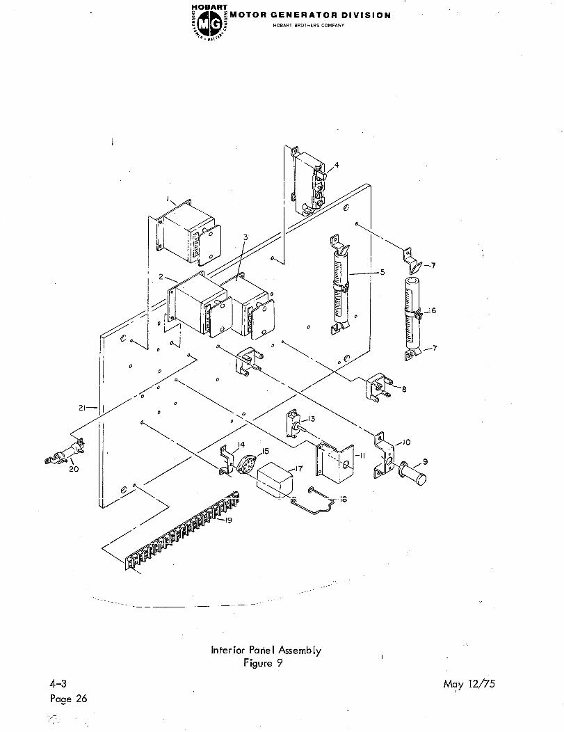
HOBART I a ‘0 QQ
;MOTOR GENERATOR DIVISION .
2 HOBART BROTHERS COMPANY
4? *. B,lT 8
Interior Patie I Assembly
Figure 9
4-3
Page 26
i ’
Ma-y 12/?‘5

FOBART z :: QQ
;MOTOR GENERATOR DlVlSlON HOBART BROTHERS COMPANY
“0 i 42 Q . B ,J
FIGURE HOBART
ITEM NO. PART N 0.
9- 481052
1 ’ 383766
2
3
4
1 ODH-845-0
1 ODH -847-2
400540-3
5 W-2974-F
6 W-2974-L
7 400078
8 404065-l
9 lODH-696-3
10
11 * 12
13
75NH-110
lOOGH-142
403336
FW-1312
14 387725
15 16DA-4052-0
* 16 363771-5
17 16DA-4004A-3
18 16DA-4253-1
19 40191 l-20
20 W-454 1 D
21 481053
N OMENC LATURE UN ITS
1234567 EFF . AgrY
PANEL ASSEMBLY, INTERIOR (For NHA
See Fig. 8)
. RE IAY, OVERVOLTAGE
RE LAY, UN DERVO LTAGE
: RELAY, UNDERFREQUENCY
RELAY, OVER LOAD VO1121,
l No. NN-1
RESISTOR V44655, No. 0960B,
l 250 Oh m, 100 W
RES ISTOR V44655, No. 0959,
’ 50 Ohm, 100 W
. BRACKET, MOUNTING, RESISTOR
V44655, No. 12
RECTIFIER, S ILICON V04713,
l No. SDA10270-1
. RELAY, TIME DE LAY V93929,
Type TF-10, 115 Volt Heater
. BRACKET, MOUNTING, RELAY
BRACKET, MOUNTING, SWITCH
: RING, LOCKING, SWITCH V91929,
No. TS 10020
SWITCH, TOGGLE VO4009, No.
’ 80600-BJ
. BRACKET, MOUNTING, SOCKET,
RELAY
SOCKET, RELAY .VO2660, No.
’ 77-MIP-11
SLEEVING, PLASTIC
: RELAY, PLUG, INTERLOCK, 24 V.
V77342, No. KAP-14DG
. SPRING, RETAINER, RELAY V77342,
No. 2OC206
STRIP, TERMINAL V88223, No. 441-20
: RESISTOR, V44655, No. 0368
. PANE L, INTER IOR
REF.
1
1
1
1
1
1
4
2
1
1
2
1
4
1
May 12p5 4-3
Page 27

4-3
Page 28
MOTOR GEN ERATOR DIVISION HOBART BROTHERS COMPANY
Regulator Box Group
Figure 10 I
May 12p5

FOBART 8 t QQ ;MOTOR GENERATOR DIVISION
d HOBART BROTHERS COMPANY “a
%. BA,\++
FIGURE PART
ITEM NO. NUMBER
lo-
I
* 1
2 I 3
4
5
6
NOMENCLATURE
1234567 EFF
No Number
50NH-829
430278
5ONH-831
430293
50N H -830
5ON H -834
50N H -707
50N H -708
BOX, REGULATOR, GROUP (For NHA
See Fig. 3)
. BOX, STATIC, EXCITER, ASSEMBLY
. . GROMMET, RUBBER V89616, No. TPRh812
. . PANEL, FRONT
. . REGULATOR, MAGNETIC, AMP
(For- Details See Fig. 11)
. . BOX, S.A.
. SUPPORT, SLIDING ASSEMBLY
. . BASE, MOUN TIN G
. . SUPPORT, S-A.
UN ITS
Per ASSY
REF
1
1
1
May 12/?‘5
Aug 2O/f5 Revised
Tfi/ -5 f- u c’
4-3
Page 29

4-3
Page 30
FOBART z QQ
;UOTOR GENERATOR DIVISION z : HOBART BROTHERS COMPANY “c 2
4G . B ,&
‘O-48
Magnetic Amp Regulator
Figure 11
May 12p5
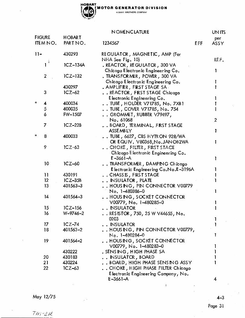
FIGURE HOBART
ITEM NO. PART NO.
FoBART I f
iMOTOR GENERATOR DIVISION HOBART BROTHERS COMPAN”
“0 QQ 2 46
Q. 0.v 6
ll-
1’
2 I
3
* 4
5
6
7 lCZ-22B
* 8 400033
9 1C Z-63
10 lCZ-60 . . TRANSFORMER, DAMPING Chicago
11 430191
12 1C Z-35B
13 401563-3
14
15 lCZ-156
16 W-9746-2
17 lCZ-74
18 401563-2
19 40 1564-2
20
21
22
May 12/75
430293
lCZ-134A
lCZ-132
430297
lCZ-62
400034
400035
FW-1507
401564-3
430222
430183
430224
lCZ-63
N OMENC LATURE
1234567
REGU LATOR , MAGNETIC, AMP (For
NHA See Fig. 10)
. REACTOR, RE GU iATCR , 300 VA
Chicago Electronic Engineering Co.
TRANSFORMER, POWER, 300 VA
’ Ch’ lcago E lectron ic Engineering Co.
. AMPLIFIER, FIRST STAGE SA
. . REACTOR, FIRST STAGE Chicago
Electronic Engineering Co.
. . TUBE, HOLDER V71785, No. 7XBl
TUBE, COVER V71785, No. 754
: : GROMMET, RUBBER V79497,
No. 61068
BOARD, TERMINAL, FIRST STAGE
.’ . ASSEMBLY
TUBE, 6627, CBS HYTRON 928fiA
’ l CR EQUIV. V80368,No.JANOBZWA
l l
CHOKE, FILTER, FIRST STAGE
Ch. Icago E lectronic Engineering Co.
E -366 1 -A
Electronic Engineering Co.No.E-3196A
. . CHASSIS, FIRSTSTAGE
. . INSULATOR, PLATE
. . HOUSING, PIN CONNECTOR VO0779
No. 1-480386-O
. . HOUSING, SOCKETCONNECTOR
VO0779, No. l-480285-0
INSULATOR
. l RES ISTOR, 750, 25 W V44655, No.
l l 0203
. . INSULATOR
. . HOUS IN G, PIN CONNECTOR VO0779,
No. l-480284-0
. . HOUSING, SOCKET CONNECTOR
VO0779, N o. l-480283-0
. SENS ING, H IGH PHASE SA
. . INSULATOR, BOARD
. . BOARD, HIGH PHASE SENSING ASSY
. . CHOKE, H IGH PHASE FILTER Chicago
Electronic Engineering Company, No.
E -366 1 -A
UN ITS
Per EFF ASSY
REF.
1
1
1
1
1
1
2
1
1
1
1
1
1
1
1
1
4
4-3
Page 31

4-3
Page 32
FOBART P a QQ
iMOTOR GENERATOR DIVISION
i HOBART BROTHERS COMPANY b 4k * . 6 g.0
May 12p5
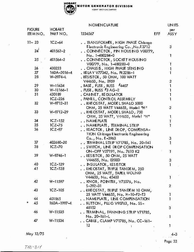
FOBART e z QQ
iMOTOR GENERATOR DIVISION -
“c 2 HOBART BROTHERS COMPANY
% *. *,I> 6
FIGURE HOBART
ITEM NO. PART NO.
ll- 23
24’
25
26
27
28
29
30
31
32
33
34
35
36
lCZ-64
401563-2
401564-2
430223
16DA-2016-4
W-2974-L
W-l 1434
W-l 1166-l
430189
lCZ-226
W-9712-31
W-9712-29
lCZ-152
lCZ-75
lCZ-97
37 402680-20
38 lCZ-70
39 W-9746-l
40 lCZ-129
41 lCZ-128
42 W-l 1597
43 lCZ-105
44 401865 * 45 16DA-1997-4
46 W-l 1535
47 W-l 1534
May 12/75
NOMENCLATURE
1234567 EFF
TRANSFORMER, HIGH PHASE Chicago
. . Electronic Engineering Co. ,No.E3712
. . CONNECTOR, PIN HOUS ING VO0779,
No. l-480284-0
CONNECTOR, SOCKET HOUSING
l l VO0779, No. l-480283-0
CHASS IS, H IGH PHASE SENS ING
l F;EIAY V77342 No. PR2286-1
1 RES IST~ , 50 OHM, 100 WATT
V44655, No. 0959
. BASE, FUSE, BUSS #4407
. FUSE, BUSS #3 AG-2
CAB INET, RE GU LATCR
: PANEL, CONTROL ASSEMBLY
RHEOSTAT, MODE L SHA LO 5000
. l OHM, 25 WATT V44655, Model “H”
. . RHEOSTAT, MODEL SHALO, 750
OHM, 25 WATT, V44655, Mode I “H ”
. . NAMEPLATE
NAME PlATE , TERMINAL STRIP
: : REACTOR, LINE DROP, COMPENSA-
TION Chicago Electronic Engineering
Co., No. E-3963
. . TERMINAL STRIP V71785, No. 20-141
. . SWITCH, LINE DROP COMPENSATION
ON-OFF V27191, No. 7610 K2
RESISTOR, 50 OHM, 25 WATT
l l V44655, No. 0200D
INSULATOR , RES ISTOR
: : RHEOSTAT, TRIPLE TANDEM, 250
OHM, 25 WATT, TAPER WOUND
V44655, No. 45403
KNOB, POINTER, V75376, No.
� l S-292-31
. . RHEOSTAT, TRIPLE TANDEM 10 OHM,
25 WATT V44655, No. H-lo-F2-T3
NAMEPLATE, LINE COMPENSATION
: : BUTTON, PLUG V90763, No. SS-
48152
TERMINAL, FANN ING STRIP V71785,
l . No. 20-161-L
CABLE, CLAMP V71785, No. CC-161-
l l 12 I
UN ITS
A&
3
1
1
1 1
2
1
1
1
1
2
1
1
1
1
2
1
1
3
1
1
4-3
Page 33

4-3
Page 34
HOBART
e QQ :MOTOR GENERATOR DIVISION
:: : HOBART BROTHERS COMPANY “0 2
B . I ,,I++
May 12n5

FOBART
e f QQ
$a’lOTOR GENERATOR DIVISION
“0 I HOBART BROTHERS COMPANY ti
B . LI ,,d
N OMENC LATURE
FIGURE HOBART
IlEMNO. PART N 0. 1234567
ll- 48 16DA-1997-3 BUTTON, PLUG V90763,
46
l ’ No. SS-48192
lCZ-101 NAMEPLATE, ADJUST
50 1c z-74 : : INSULATOR EPOXY MICA 0012 ,
51 I W-9026-9 . . RESISTOR V44655, 3000 OHM,
10 WATT
52 400032 . . BRACKET, MTG. RESISTOR V44655
No. 5
53 430188 . i PANEL, CONlROL
May 12n5
UN ITS
EFF A%
1
1
3
1
2
1
I
4-3
Page 35
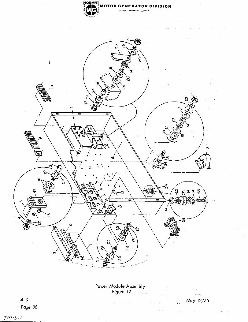
FOBART
z 5 QQ
;MOTOR GENERATOR DlVlSlON
“0 2 HOBART BROTHERS COMPANY
*F *. sh,+*
4-3
Page 36
Power Module Assembly
Figure 12 I
May ‘lip5
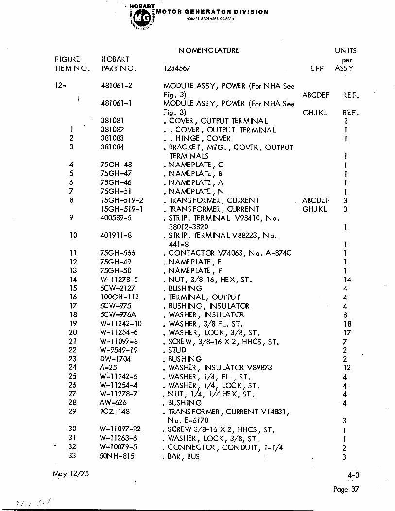
j FOBAFt?
e :, QQ
iMOTOR GENERATOR DIVISION HOBART BROTHERS COMPANY
“0 : % c 0. #),I+
FIGURE HOBART
ITEM NO. PART NO.
NOMENCLATURE UN ITS
1234567 EFF ASP;?;
12- 481061-2
1 ’ 2
3
9
10 40191 l-8
11 75GH -566
12 75GH-49
13 75GH -50
14 W-l 1278-5
15 5CW-2127
16 lOOGH-112
17 5Cw-975
18 5CW-976A
19 W-l 1242-10
20 W-l 12546
21 W-l 1097-8
22 w-9549-19
23 DW-1704
24 A-25
25 W-l 1242-5
26 W- 11254-4
27 W- 11278-7
28 AW-626
29 lCZ-148
30 W- 11097-22
31 W- 11263-6 * 32 w- 10079-5
33 5ONH-815
May 12n5
481061-l
381081
381082
381083
381084
75GH -48
75GH -47
75GH -46
75GH-51
15GH-519-2
15GH-519-1
400589-5
MODULE ASSY, POWER (For NHA See
Fig. 3) ABCDEF
MODULE ASSY, POWER (For NHA See
Fig. 3) GHJ KL
COVER, OUTPUT TERMINAL
: . COVER, OUTPUT TERMINAL
. . HINGE, COVER
BRACKET, MTG., COVER, OUTPUT
. TERMINALS
. NAMEPLATE, C
. NAMEPLATE, B
. NAMEPlATE, A
. NAMEPLATE, N
. TRANSFORMER, CURRENT
. TRANSFORMER, CURRENT
. STRIP, TERMINAL V98410, No.
38012-3820
ABCDEF
GHJ KL
. STRIP, TERMINAL V88223, No.
441-8
. CONTACTOR V74063, No. A-874C
. NAMEPLATE, E
. NAMEPLATE, F
NUT, 3/8-16, HEX, ST.
: BUSHING
. TERMINAL, OUTPUT
. BUSHING, INSULATOR
. WASHER, INSULATOR
WASHER, 3/8 FL. ST.
: WASHER, LOCK, 3/8, ST.
. SCREW, 3,‘8-16 X 2, HHCS, ST.
. STUD
. BUSHING
. WASHER, INSULATOR V89873
WASHER, l/4, FL., ST.
: WASHER, l/4, LOCK, ST.
NUT, l/4, l/4 HEX, ST.
: BUSHING
. TRANSFORMER, CURRENT V14831,
No. E-6170
SCREW 3/8-16 X 2, HHCS, ST.
: WASHER, LOCK, 3/8, ST.
. CONNECTOR, CONDUIT, l-1/4
. BAR, BUS I
REF.
REF.
1
1
1
1
1
1
1
1
14
4
4
4
8
18
17
7
2
2
12
4
1
4
3
1
1
2
3
4-3
Page 37

FCDBARZ
z QQ ;MOTOR GENERATOR DIVISION
f : z HOBART BROTHERS COMPANY
“c
b. s,,\@-
Page 38
’ May 12n5

YOBAR’G:
e z QQ
jMOTOR GENERATOR DIVISION
i HOBART BROTHERS COMPANY “c b . I) ,,R
N OME NC lATURE UN ITS FIGURE HOBART
ITEM NO. PART NO. 1234567 EFF ASP;?;
12- 34 381086
36 33
w- 11097-3 :
BOX, POWER MODULE 1 SCREW, 3/8-16 x l-1/4 HHC, ST.
W-11242-12 WASHER, FLAT, l/2, ST. : * 37 TRY-154-l : CAPACITOR V14101, No. 2OOP1868,
’
3MFD, 660 V. F 1
* 38 TRY-174-3 . BRACKET, MTG., CAPACITOR V14101,
Type 3-36-161, No. 2OOP1823 F 1
May 12n5
I
4-3
Page 39

FOBART
e I ; QQ
;MOTOR GENERATOR DIVISION -
2 HOBART BROTHERS COMPANY
46 Q. B&O 6
24.
25
Mounting Frame & Trailer Group
Figure 13 I
May 12n5 4-3
Page 40

FOBART
s a QQ
yMOTOR GENERATOR DIVISION HOBART BROTHERS COMPANY
“0 i 46 *. BL,l~e
FIGURE HOBART
ITEM NO. PART NO.
13- No Number
1 ’ 60GH-92
2
3 ,
4
5
6
7 HF-1882
8 HF-1900
9
10
11
12 * 13
* 14 DW-3342
15 H F-2266
16 W-9558-l 0
17 5ONH-196
* 18 12CW-869
19 12CW-873
20 12C W-880
21 12CW-871
22 5CN H-142
23 H F-2698
24 12CW-882
25 xw-930
May 12/“75
50N H -743
381090
W-4460B -26
6FW-5937-2
50NH-191
5CNH-150
50NH-151
50NH-152
HF-1902
HF-1899
HF-1885
50NH-194 12CW-870
DW-4 135
N OME NC LATURE
1234567 EFF
MOUNTING FRAME & TRAILER
GROUP (For NHA See Fig. 1)
. YOKE ASSEMBLY, LIFTING
FRAME ASSEMBLY, MOUNTING
: SUPPORT, MOUNTING, CONTROL
BOX, REGULATOR 8, POWER MODULE
TRAILER ASSEMBLY (COMPLETE)
: . TRAILER ASSEMBLY
CEJ L
CEJ L
AXLE ASSEMBLY, REAR
: : : BRAKE ASSEMBLY
CEJ L
CEJ L
. . . . LEVER & BRAKE MOUNT ASSY CEJL
. . . . ANGLE ASSY, MOUNTING,
BRAKE SHOE CEJ L
. . . . SHOE ASSY, BRAKE CEJ L
. . . . ROD ADJUSTING BRAKE
(RIGHT HAND) CEJ L
. . . . ROD ADJUSTING BRAKE
(LEFT HAND) CEJ L
. . . . BRACKET, MOUNTING, BRAKE
SHOE ANGLE CEJ L
. . . . GLEVIS ASSEMBLY, ADJUST.
-BRAKE CEJ L
. . . AXLE ASSEMBLY, FRONT CEJ L
. . . . SPINDLE ASSY, RIGHT FRONT CEJL
. . . . BOLT, RADIUS ROD TO RADIUS
ARM(5/8x l8x2)CASTELNUT
(5/8 x 18) CEJ L
. . . . PIN, KING CEJ L
. . . . CLEVIS, TIE ROD TOSPINDLE CEJL
. . . . ROD, TIE CEJ L
. . . . AXLE, FRONT CEJ L
. . . . BOLT, HITCH CEJ L
. . . . HITCH ASSY, TRAILER CEJ L
. . . . BLOCK, MTG., TIE ROD CEJL
SPINDLE ASSY, LEFT, FRONT CEJL
1 1 1 ~HANNE L, MTG. FRONT AXE
TO FRAME CEJ L
SHAFT, PIN ION, FRONT AXLE
: : : TONGUE, TRAILER CEJ L
CEJ L
. . . CUP, BEARING V60038, No.
T-50,000 CEJ L
I
UN ITS
A”s’u
REF.
1
1
1
1
4
1
1
2
2 1
1
2
2
2
2
1
1
1
2
1
4
4-3
Page 41

4-3
Page 42
~ORAR~
e a QQ
;MOTOR GENERATOR DIVISION
“c d HOBART BROTHERS COMPANY
46 0. 8.0 8
May 12p5
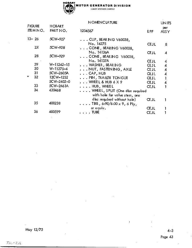
FIGURE HOBART
ITEMNO. PART N 0.
13- 26 5C W-927
271 5CW-928
28 5C W-929
FOBARX
I ::
;MOTOR GENERATOR DIVISION
“c QQ 2 HOBART BROTHERS COMPANY
46 8 Q. II,>\
29
30
31 * 32
33
34
35 400238
36 400599
W-l 1242-15 W- 11275-4 5C W-260$,
12CW-1232
5C W-2402-0
5CW-246 1A 430468
NOMENCLATURE
1234567 EFF
. . . CUP , BEAR IN G V60038,
No. 14275
. . . CONE , BEAR IN G V60038,
No. 14136A
CONE, BEAR IN G V60038,
. . l No. 14137A
WASHER, BEAR IN G
: : : NUT, FASTENING, AXLE
CAP, HUB
: : : PIN, TRAILER TONGUE
CEJ L
CEJ L
CEJ L
CEJ L
CEJ L
CEJ L
CEJ L . . . WHEEL&HUB6X9 CEJ L
. . . . HUB, WHEE L CEJ L
. . . . WHEEL, SPLIT (One disc required
with hole for valve stem, one
disc required without hole) CEJ L
. . . . TIRE, 6:90/6:00 x 9, 6 Ply, or equiv. CEJ L
. . . . TUBE CEJ L
UN ITS
A&
8
4
1
1 1
I
4-3
Page 43

MOTOR GENERATOR DIVISION HOBART BROTHERS COMPANY
.I
Power Factor Correction Capacitors
(Specs 4713A, Var. 5)
Figure 14 I
4-3
Page 44
T,/ i u 5 ,i,J
May 12/‘75
Revised Aug 2Ofl5
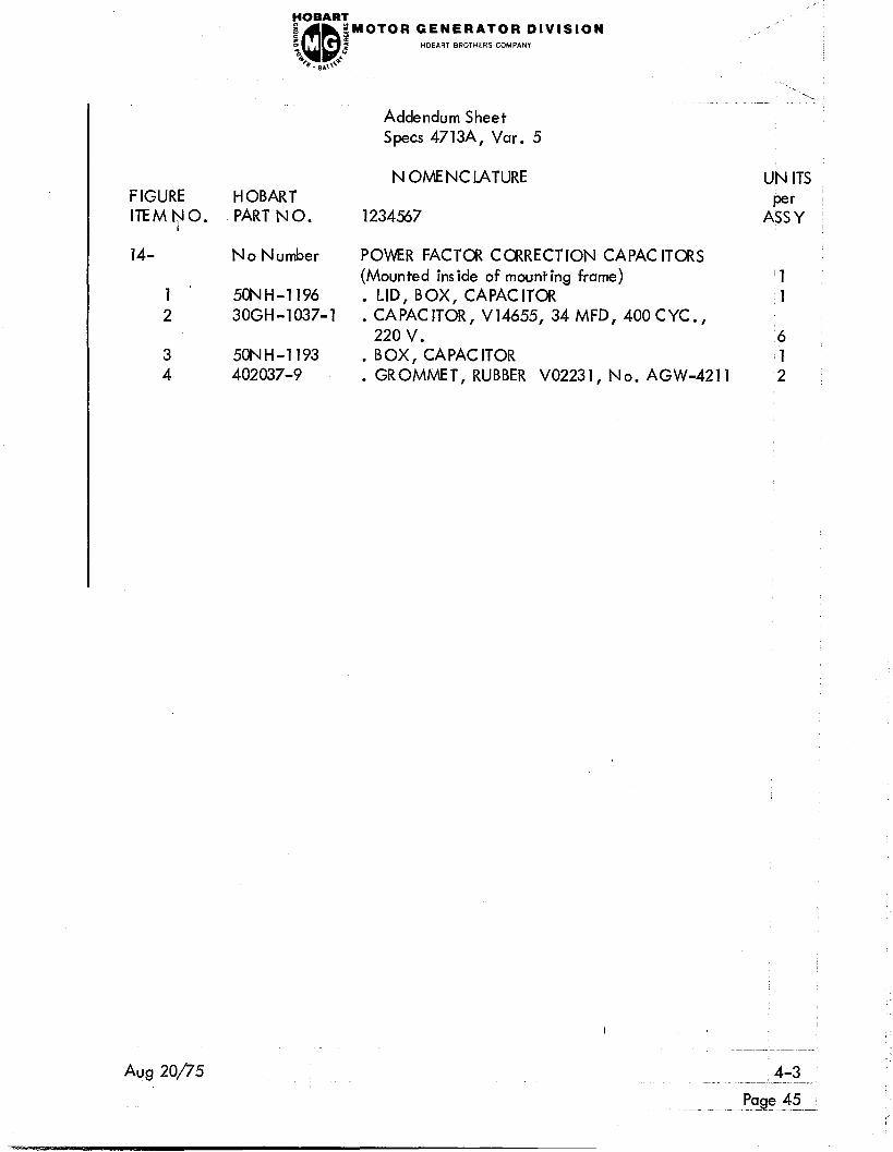
rOBART
8 f QQ
gMOTOR GENERATOR DIVISION
“c i HOBART BROTHERS COMPANY
48 ‘* Q. .gkO Addendum Sheet
Specs 4713A, Var. 5
FIGURE HOBART
ITEMNO. PART NO.
14- No Number
I 1 5CNH-1196
2 3OGH-1037-1
3 5ONH-1193
4 402037-9
N OME NC LATURE
1234567
POWER FACTOR CORRECTION CAPACITORS
(Mounted ins ide of mounting frame)
LID, BOX, CAPACITOR
: CAPACITOR, V14655, 34 MFD, 400 CYC.,
220 v.
BOX, CAPAC ITOR
: GROMMET, RUBBER V02231, No. AGW-4211
I
Aug 20/75
UN ITS
A&
‘1
.1
16
1
‘2
Page 45

FOBART
e, QQ ;MOTOR GENERATOR DIVISION
c p: 2 HOBART BROTHERS COMPANY
“0
%. ,,,I6
I
4-3
Page 46
,-
Aug 20/75
- -... ~. __. _. -

YOBAR?
e QQ :MOTOR GENERATOR DIVISION
z s 2 HOBART BROTHERS COMPANY
“c
% . 8 @--
ADDENDUM
to
4713A INSTRUCTION S TM-318
for
4713A - Variation 4
with
PHASE REVERSAL RELAY
(For machines connected for 460-V input only)
The generator set identified as Specification No. 4713A-Variation 4 is equipped
with a phase reversal relay which prevents operation of the motor (and generator)
in a reverse direction. This feature is very useful especially when the generator
set is moved and reconnected frequently.
The relay is connected in the motor start circuit to prevent the motor from starting
if input power is connected in a reverse phase sequence.
If the motor will not start when the START switch is pushed, reverse the connection
of any two of the three input cables (Ll, L2, L3) to connect forproper phase sequence
and motor rotation.