TM 11-5995-208-24&P - Liberated Manuals.com · tm 11-5995-208-24&p c5 change headquarters...
101
TM 11-5995-208-24&P ORGANIZATIONAL, DIRECT SUPPORT AND GENERAL SUPPORT MAINTENANCE MANUAL FOR CABLE ASSEMBLY, SPECIAL PURPOSE CX-11230/G (5995-00-133-9126) HEADQUARTERS, DEPARTMENT OF THE ARMY WASHINGTON, D. C. SEPTEMBER 1978
Transcript of TM 11-5995-208-24&P - Liberated Manuals.com · tm 11-5995-208-24&p c5 change headquarters...
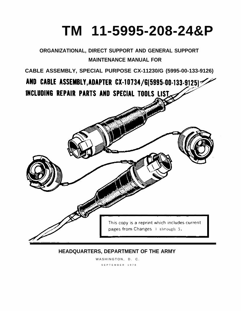
TM 11-5995-208-24&PORGANIZATIONAL, DIRECT SUPPORT AND GENERAL SUPPORT
MAINTENANCE MANUAL FOR
CABLE ASSEMBLY, SPECIAL PURPOSE CX-11230/G (5995-00-133-9126)
HEADQUARTERS, DEPARTMENT OF THE ARMYW A S H I N G T O N , D . C .
S E P T E M B E R 1 9 7 8

W A R N I N G
WHEN YOU ARE TROUBLESHOOTING, DO NOT OPEN ANY CABLE
CONNECTION.
0PENING A CONNECTION CAN EXPOSE YOU TO A FATAL SHOCK BY
HIGH VOLTAGE.
BUT,
IF YOU FIND IT IS NECESSARY TO REMOVE OR REPLACE A COMPONENT
OR A CABLE SECTION IN THE SYSTEM,
USE YOUR ORDER WIRE HOOKUP
AND CALL THE MUX EQUIPMENT OPERATORS AND TELL THEM TO
REMOVE THE POWER FROM THE CABLE HOOKUP.

TM 11-5995-208-24&PC 5
CHANGE HEADQUARTERSDEPARTMENT OF THE ARMY
No. 5 Washington, DC, 9 July 1984
ORGANIZATIONAL, DIRECT SUPPORT AND GENERAL SUPPORT MAINTENANCEMANUAL FOR
CABLE ASSEMBLY, SPECIAL PURPOSE, CX-11230/G (NSN 5995-00-133-9126) ANDCABLE ASSEMBLY, ADAPTER CX-10734/G (NSN 5995-00-133-9125)
INCLUDING REPAIR PARTS AND SPECIAL TOOLS LIST
Change 5 is current as of
TM 11-5995-208-24&P, 26 September 1978, is changed as follows:
1. New or changed material is indicated by a vertical bar in the margin of the page.
2. Remove and insert pages as indicated below.
Remove pages Insert pages
iiiand iv . . . . . . . . . . . . . . . . . . . . . . . . . . . .iii and iv2-3 and 2-4 . . . . . . . . . . . . . . . . . . . . . . . . . .2-3 and 2-42-7 and 2-8 . . . . . . . . . . . . . . . . . . . . . . . . . . .2-7 through 2-8.1/(2-8.2 blank)3-l through 3-4 . . . . . . . . . . . . . . . . . . . . . .3-l through 3-43-33 and 3-34 . . . . . . . . . . . . . . . . . . . . . . . .3-33 and 3-343-39 and 3-40 . . . . . . . . . . . . . . . . . . . . . . . .3-39 and 3-40A-l and A-2 . . . . . . . . . . . . . . . . . . . . . . . . . A-l and A-2
3. File this change sheet in front of the publication.
By Order of the Secretary of the Army:
Official:
ROBERT M. JOYCEMajor General, United States Army
The Adjutant General
JOHN A. WICKHAM JR.General, United States Army
Chief of Staff
Distribution:
To be distributed in accordance with DA Form 15-51 B requirements for CX-11230/G.


WARNING
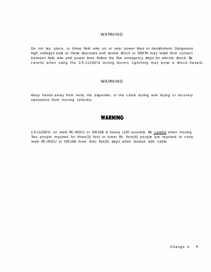
Do not lay, place, or throw field wire on or near power lines or transformers. Dangeroushigh voltages exist at these structures and severe shock or DEATH may result from contactbetween field wire and power lines. Follow the five emergency steps for electric shock. Becareful when using the CX-11230/G during storms. Lightning may pose a shock hazard.
WARNING
Keep hands away from reels, the dispenser, or the cable during wire laying or recoveryoperations from moving vehicles.
CX-11230/G on reels RC-453/U or DR-15B is heavy (120 pounds). Be careful when moving.Two people required for three(3) foot or lower lift. Four(4) people are required to carryreels RC-453/U or DR-15B more than five(5) steps when loaded with cable.
Change 4 A
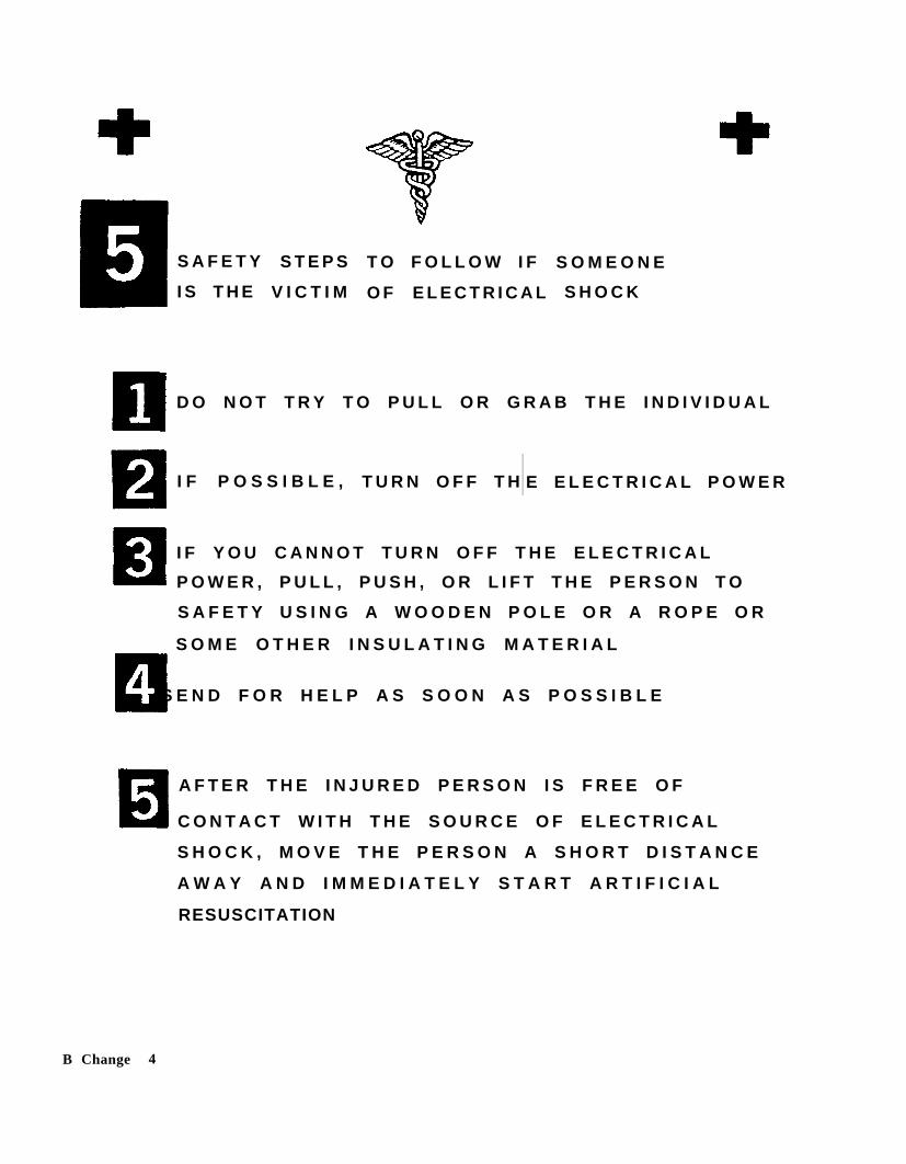
S A F E T Y
I S T H E
S T E P S
V I C T I M
T O F O L L O W I F
O F E L E C T R I C A L
S O M E O N E
S H O C K
D O N O T T R Y T O P U L L O R G R A B T H E I N D I V I D U A L
I F P O S S I B L E , T U R N O F F T H E E L E C T R I C A L P O W E R
I F Y O U C A N N O T T U R N O F F T H E E L E C T R I C A L
P O W E R , P U L L , P U S H , O R L I F T T H E P E R S O N T O
S A F E T Y U S I N G A W O O D E N P O L E O R A R O P E O R
S O M E O T H E R I N S U L A T I N G M A T E R I A L
S E N D F O R H E L P A S S O O N A S P O S S I B L E
A F T E R T H E I N J U R E D P E R S O N I S F R E E O F
C O N T A C T W I T H T H E S O U R C E O F E L E C T R I C A L
S H O C K , M O V E T H E P E R S O N A S H O R T D I S T A N C E
A W A Y A N D I M M E D I A T E L Y S T A R T A R T I F I C I A L
RESUSCITATION
B Change 4


TM 11-5995-208-24&P
W A R N I N G
E X T R E M E L Y H I G H V O L T A G E S E X I S T W H E N Y O U A R E U S I N G T H E
INSULATION BREAKDOWN TEST SET AN/GSM-6,
VOLTAGES AS HIGH AS 40,000 VOLTS MAY EXIST AT THE FOLLOWING:
O U T P U T T E R M I N A L S
O U T P U T C A B L E
CABLE UNDER TEST.
DON’T TAKE CHANCES, BE EXTREMELY CAREFUL
SERIOUS INJURY OR DEATH MAY RESULT IF YOU ARE NOT CAREFUL
i

TM 11-5995-208-24&P
H O W
T O U S E
T H I S M A N U A L
This technical manual covers the maintenance procedures for special Pulse Code Modu-lation (PCM) cables.
Step-by-step procedures with illustrations will give you all the necessary information torepair TWIN COAX CABLE (CX-11230/G). These steps must be followed in the exactsequence shown. Do not attempt any short cuts.
Throughout this manual you will find many drawings of cable repair parts. Alongsideeach part is a solid orange number. This number is the same number as the one listed inthe packing list.
Before attempting any procedure described in this technical manual, you should famil-iarize yourself with the entire procedure before beginning the job.
AFTER YOU HAVE HAD SOME TIME TO USE THIS MAN-
UAL, TAKE A MOMENT TO LET US KNOW WHAT YOUTHINK ABOUT IT. PLEASE USE THE SELF-ADDRESSEDQUESTIONNAIRE IN THE BACK OF THE MANUAL. FOLDWHERE SHOWN AND DROP IT IN THE MAIL.
ii
*TM 11-5995-208-24&P
Technical Manual HEADQUARTERSDEPARTMENT OF THE ARMY
No. 11-5995-208-24&P Washington, DC, 26 September 1978
ORGANIZATIONAL, DIRECT SUPPORT AND GENERAL SUPPORT MAINTENANCE MANUALFOR
CABLE ASSEMBLY, SPECIAL PURPOSE, CX-11230/G (NSN 5995-00-133-9126) ANDCABLE ASSEMBLY, ADAPTER CX-10734/G (NSN 5995-00-133-9125)
INCLUDING REPAIR PARTS AND SPECIAL TOOLS LIST
C u r r e n t a s o f 3 1 M a r c h 1 9 8 4
CHAPTER 1
REPORTING ERRORS AND RECOMMENDING IMPROVEMENTS
You can help improve this manual. If you find any mistakes or if you know of a way toimprove the procedures, please let us know. Mail your letter, DA Form 2028 (Recom-mended Changes to Publications and Blank Forms), or DA Form 2028-2 located in theback of this manual direct to: Commander, US Army Communications-ElectronicsCommand and Fort Monmouth, ATTN: DRSEL-ME-MP, Fort Monmouth, New Jersey07703. In either case, a reply will be furnished direct to you.
Page
HOW TO USE THIS MANUAL ii
INTRODUCTION 1-1
Section I General Information (Includingnomenclature cross-reference list) 1-1
Section II Equipment Description and Data 1-6
*This manual together with TM 11-5995-208-10 supersedes TM 11-5995-208-15, 9 August 1972.
Change 5 iii

TM 11-5995-208-24&P
CHAPTER 2Section I
Section IISection III
Section IVSection V
Section VI
CHAPTER 3Section I
Section IISection IIISection IVSection V
APPENDIX A
APPENDIX B
APPENDIX C
APPENDIX D
ORGANIZATIONAL MAINTENANCERepair Parts, Special Tools andTest-Measuring-DiagnosticEquipment
Service Upon ReceiptOrganizational Preventive Maintenance
Checks and ServicesTroubleshootingOrganizational Maintenance and
Repair ProceduresStorage
GENERAL SUPPORT MAINTENANCERepair Parts, Special Tools and Test-Measuring-Diagnostic Equipment
Service Upon ReceiptStorageTwin Coax Cable (CX-11230/G) RepairPerformance Standards
REFERENCES
MAINTENANCE ALLOCATION CHART
REPAIR PARTS AND SPECIAL TOOLS LIST
EXPENDABLE SUPPLIED AND MATERIALS LIST
Page2-1
2-12-3
2-42-8
2-92-10
3-1
3-13-13-13-33-33
A-1
B-1
C-1
D-1
iv
TM l l -5995-208-24&P
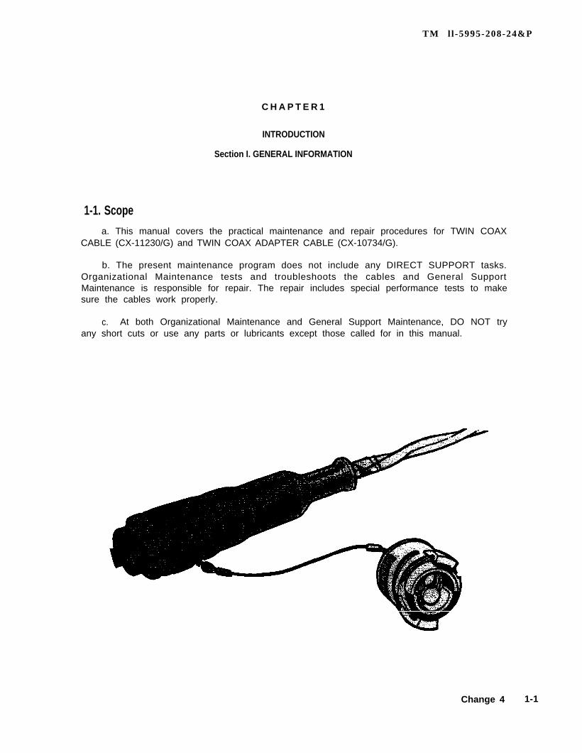
C H A P T E R 1
INTRODUCTION
Section I. GENERAL INFORMATION
1-1. Scopea. This manual covers the practical maintenance and repair procedures for TWIN COAX
CABLE (CX-11230/G) and TWIN COAX ADAPTER CABLE (CX-10734/G).
b. The present maintenance program does not include any DIRECT SUPPORT tasks.Organizational Maintenance tests and troubleshoots the cables and General SupportMaintenance is responsible for repair. The repair includes special performance tests to makesure the cables work properly.
c. At both Organizational Maintenance and General Support Maintenance, DO NOT tryany short cuts or use any parts or lubricants except those called for in this manual.
Change 4 1-1

1-5.
1-2. Purpose of EquipmentProvides transmission paths fortions systems.
signals in PCM (pulse code modulation) communica-
1-3. Maintenance Forms, Records, and Reports
a. Reports of Maintenance and Unsatisfactory Equipment. Department of theArmy forms and procedures used for equipment maintenance will be those prescribedby TM 38-750, The Army Maintenance Management System (TAMMS).
b. Report of Packaging and Handling Deficiencies. Fill out and forward SF 364(Report of Discrepancy (ROD)) as prescribed in AR 735-11-2.
c. Discrepancy in Shipment Report (DISREP) (SF 361). Fill out and forwardDiscrepancy in Shipment Report (DISREP) (SF 361) as prescribed in AR 55-38.
1-4.
Destruction of Army electronics materiel to prevent enemy use shall be in accordancewith TM 750-244-2.
The storage of these PCM cables must be carefully done. Complete instructions will befound in Chapter 2 in this manual.
1-6.
After OVERHAUL or FABRICATION or SCREENING of TWIN COAX CABLE (CX-11230/G)the cable must be checked using the performance standards found in Chapter 3 in themanual.
1-7.
If your equipment needs improvement, let us know. Send us an EIR. You, the user, arethe only one who can tell us what you don’t like about your equipment. Let us know whyyou don’t like the design. Tell us why a procedure is hard to perform. Put it on an SF 368(Quality Deficiency Report). Mail it to Commander, US Army Communications-Electronics Command, ATTN: DRSEL-ME-MQ, Fort Monmouth, New Jersey 07703.We’ll send you a reply.
1 - 2
TM 11-5995-208-24&P
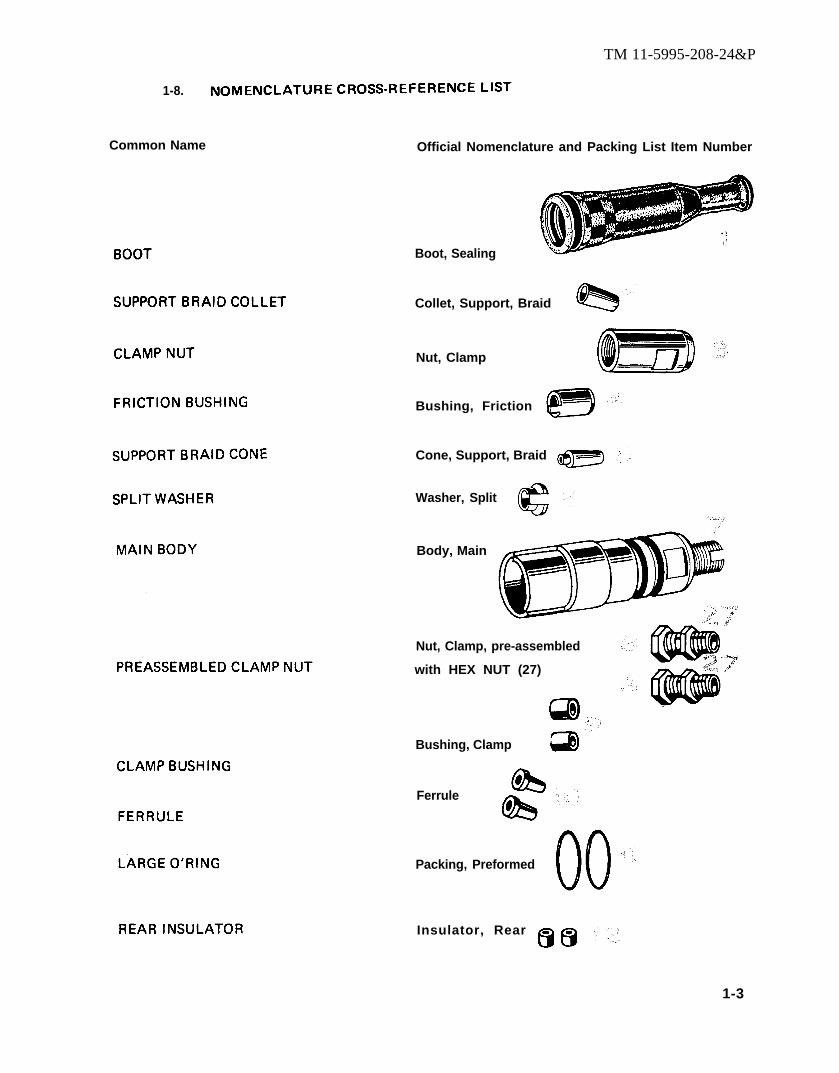
1-8.
Common Name Official Nomenclature and Packing List Item Number
Boot, Sealing
Collet, Support, Braid
Nut, Clamp
Bushing, Friction
Cone, Support, Braid
Washer, Split
Body, Main
Nut, Clamp, pre-assembled
with HEX NUT (27)
Bushing, Clamp
Ferrule
Packing, Preformed
Insulator, Rear
1-3

TM ll-5995-208-24&P
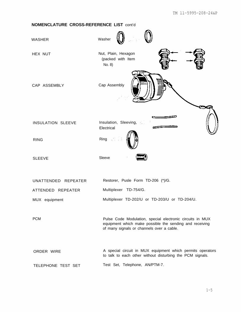
NOMENCLATURE CROSS-REFERENCE LIST cont’d
MAIN BODY INSULATOR Insulator, Main Body
O’RING
O’RING
COUPLING NUT
FEMALE BODY ASSEMBLY
MALE CONTACT
FRONT MALE INSULATOR
MALE BODY ASSEMBLY
FEMALE CONTACT
FRONT FEMALE INSULATOR
NON–METALLIC WASHER
O’RING
SCREW
1-4
Packing, Preformed
(Usually found installedon items 19and 22)
Packing, Preformed
Nut, Coupling
Body Assembly, Female
Contact, Male
Insulator, Front, Male, Pre-assembled with 1 eachItem No. 14
Body Assembly, Male
Contact, Female
Insulator, Front, Female,Pre-assembled with 1 eachItem No. 14
Washer, Non-metallic
Packing, Preformed
Screw r Self Locking
TM ll-5995-208-24&P
NOMENCLATURE CROSS-REFERENCE LIST cont’d
WASHER Washer
CAP ASSEMBLY
HEX NUT Nut, Plain, Hexagon(packed with Item
No. 8)
Cap Assembly
INSULATION SLEEVE Insulation, Sleeving,Electrical
RING Ring
SLEEVE Sleeve
UNATTENDED REPEATER Restorer, Pusle Form TD-206 (*)/G.
ATTENDED REPEATER Multiplexer TD-754/G.
MUX equipment Multiplexer TD-202/U or TD-203/U or TD-204/U.
PCM
ORDER WIRE
TELEPHONE TEST SET
Pulse Code Modulation, special electronic circuits in MUXequipment which make possible the sending and receivingof many signals or channels over a cable.
A special circuit in MUX equipment which permits operatorsto talk to each other without disturbing the PCM signals.
Test Set, Telephone, AN/PTM-7.
1-5

TM ll-5995-208-24&P
SECTION II
EQUIPMENT DESCRIPTION AND DATA
1-9. EQUIPMENT CHARACTERISTICS, CAPABILITIES AND FEATURES
a. TWIN COAX CABLE (CX-1230/G).
Contains two small coaxial cables.
Carries up to 48 channels of PCM signals.
Can be laid on the ground, suspended from poles or trees, or buried.
Requires an UNATTENDED REPEATER at the end of each mile (1.6 kilo-meters) of cable.
Cable also carries dc power for the UNATTENDED REPEATER.
This dc power is supplied by the MUX equipment connected to thecable.
Requires an ATTENDED REPEATER every 40 miles (64 kilometers).
Available in 100 foot (30.48 meters) or one-quarter mile (402 meters) lengths.
b. TWIN COAX ADAPTER CABLE (CX-10734/G).
Overall length is 4 feet (1.2 meters). Weight is 3 pounds.
Contains the same type small coaxial cables as TWIN COAX CABLE(CX-11230/G).
Used to connect TWIN COAX CABLE (CX–11230/G) to:
MUX equipment
or
early model UNATTENDED REPEATERS
or
ATTENDED REPEATERS
or
other PCM cables like the CX–4245/G.
1-6 Change 3

TM ll-5995-208-24&P
1-10. PERFORMANCE DATA
a. TWIN COAX CABLE (CX-11230/G).
CHANNEL CAPACITY
6, 12, 24 or 48 channels.
INSULATION QUALITY
Each coaxial cable can withstand up to 2,500 volts dc between its centerconductor and its shield.
INSULATION RESISTANCE
For each coaxial cable, 50,000 megohms between its center conductorand its shield.
CHARACTERISTIC IMPEDANCE
DC
DC
55 to 65 ohms in the range of 400 kHz to 1,000 kHz.
55 to 60 ohms in the range of 1,000 kHz to 3,000 kHz.
RESISTANCE OF THE CENTER CONDUCTOR IN EACH COAXIAL CABLE
22 ohms for each 1,320 feet (1/4 mile or 402 meters).when the temperature is 20 degrees Celsius.
RESISTANCE OF THE SHIELD IN EACH COAXIAL CABLE
ohms for each 1,320 feet (1/4 mile or 402 meters).when the temperature is 20 degrees Celsius.
SIGNAL ATTENUATION
8.5 dB per mile (1.6 kilometers) at 100 kHz.
38 dB per mile (1.6 kilometers) at 2,000 kHz.
TENSILE STRENGTH
600 pounds.
TENSILE STRENGTH
OF CABLE
OF CABLE-TO-CONNECTOR JUNCTION
400 pounds.
WEIGHT
8 pounds for 100 foot length and 77 pounds for 1/4 mile length.
1-7
TM ll-5995-208-24&P
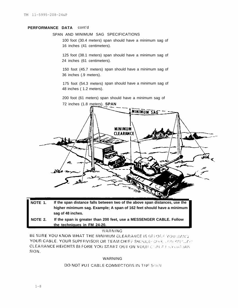
PERFORMANCE DATA
SPAN AND
100 foot (30.4 meters) span should have a minimum sag of16 inches (41 centimeters).
cont’d
MINIMUM SAG SPECIFICATIONS
125 foot (38.1 meters) span should have a minimum sag of
24 inches (61 centimeters).
150 foot (45.7 meters)
36 inches (.9 meters).
175 foot (54.3 meters)48 inches ( 1.2 meters).
span should have a minimum sag of
span should have a minimum sag of
200 foot (61 meters) span should have a minimum sag of
72 inches (1.8 meters). SPAN
NOTE 1. If the span distance falls between two of the above span distances, use thehigher minimum sag. Example; A span of 162 feet should have a minimumsag of 48 inches.
NOTE 2. If the span is greater than 200 feet, use a MESSENGER CABLE. Followthe techniques in FM 24-20.
WARNING
1-8
TM ll-5995-208-24&P
PERFORMANCE DATA cont’d
b. TWIN COAX ADAPTER CABLE (CX-10734/G).
CANNOT BE USED IN A SPAN
TENSILE STRENGTH
45 pounds at the ends connected to the UG–1871/U connector or the
UG–1872/U connector.
CAPACITY AND TRANSMISSION CHARACTERISTICS
1-11.
a.
Data for TWIN COAX CABLE (CX-11230/G) apply.
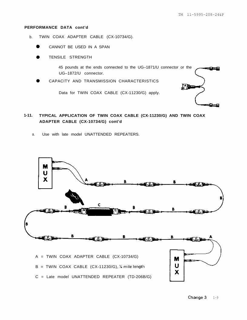
TYPICAL APPLICATION OF TWIN COAX CABLE (CX-11230/G) AND TWIN COAX
ADAPTER CABLE (CX-10734/G) cont’d
Use with late model UNATTENDED REPEATERS.
A = TWIN COAX ADAPTER CABLE (CX-10734/G)
B = TWIN COAX CABLE (CX-11230/G),
C = Late model UNATTENDED REPEATER (TD-206B/G)
1-9
TM ll-5995-208-24&P
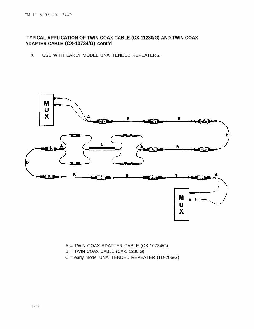
TYPICAL APPLICATION OF TWIN COAX CABLE (CX-11230/G) AND TWIN COAXADAPTER CABLE (CX-10734/G) cont’d
b. USE WITH EARLY MODEL UNATTENDED REPEATERS.
A = TWIN COAX ADAPTER CABLE (CX-10734/G)B = TWIN COAX CABLE (CX-1 1230/G)C = early model UNATTENDED REPEATER (TD-206/G)
1-10

Section I.Section I.
TM ll-5995-208-24&P
C H A P T E R 2
ORGANIZATIONAL MAINTENANCE
2-1. REPAIR PARTS
Organizational maintenance is authorized to perform the following:
a. Replacement of the CAP (part of the CAP ASSEMBLY) on CONNECTOR
b. Tightening the SCREW holding the screw lug on the retaining wire connectedto the CAP.
2-1

TM 11-5995-208-24&P
2-2. SPECIAL TOOLSThe tools authorized for organizational maintenance are listed in Appendix B.
2-3. TEST-MEASURING-DIAGNOSTIC EQUIPMENTThe fOllowing is authorized for organizational maintenance:
TELEPHONE TEST SET (AN/PTM-7)
2 - 2

TM 11-5995-208–24&P
Section II. SERVICE UPON RECEIPT
2-4. INITIAL INSPECTION
Never assume that newly received TWIN COAX CABLES (CX-11230/G) or TWIN COAXADAPTER CABLES (CX-10734/G) are all perfectly serviceable. Upon receipt, carefullyperform a visual inspection to make sure that:
a. ALL CONNECTORS (UG-1870/U) are properly capped.
b. An ID tag is attached with the following information:
(1) NOMENCLATURE.
(2) LENGTH.
(3) YEAR and MONTH.
(4) TYPE of ACTION:
SCR for SCREENEDor
NOTEYou may not f ind thistag on older cables.
OVH for OVERHAULEDor
FAB for FABRICATED.
(5) UNIT lDENTIFICATION (who did the OVH or FAB orSCR).
c. All reels are sound and can be used on the proper reel machine.
2.5. QUALITY CHECK
a. Do all the PMCS Items in Table 2-1.
b. Perform a dynamic test.
NOTE
Your organization should have a standard procedure for
checking the quality of newly received cables.
This procedure should include a performance test with the
cables connected in a working PCM circuit with the MUXequipment.
2-3

TM 11-5995-208-24&P
2-4
Section III. ORGANIZATIONAL PREVENTIVE MAINTENANCE CHECKS ANDSERVICES
2-6. GENERAL
To be sure that your cables will be able to support your mission, you must do scheduledPREVENTIVE MAINTENANCE CHECKS AND SERVICES (Table 2-1).
BEFORE cables are placed in storage, do all the PMCS items. This will help youkeep your cables in top shape.
AFTER cables are removed from storage, and before releasing to a cable laying crew,do all the PMCS items to make sure your cables are ready to go.
MONTHLY PMCS are important steps you should do on cables belonging to your unitand which are not hooked up to an operating system. These steps should keep serious
problems from suddenly happening. If you waited to do a PMCS on these cables justbefore your mission, you may find that you do not have enough cables.
Change

TM 11-5995-208-24&P
2-7.
The following are ROUTINE CHECKS AND SERVICES and are not listed in your PMCS
table. These checks and services should be done anytime you see that they must be done.
a. Cleaning the outer black plastic jacket on all cables.
(1) Use clear water and a clean rag to remove mud and dirt.
(2) Use soapy water and then rinse with clear water to remove oil orgrease.
CAUTION: Do not use SOLVENTS.
b.
c.
Capping CONNECTOR UG-1870/U.
(1) Always cap it when not in use (including storage).
(2) Always mate the caps when in use.
Connectors UG-1871/U and UG-1872/U.
(1) Always mate them to each other when not in use (including storage).
NOTE
If you find what you consider a ROUTINE CHECK ANDSERVICE in the PMCS table, it was listed because otherorganizations reported it as a critical procedure.
Change 4 2-5

Table 2-1.
TM 11-5995-208-24&P
2-6

TM 11-5995-208-24&P
2-7

Table 2-1.
2-8
TM
11-5995-208-24&
P

Section IV.
TM 11–5995–208–24&P
2-8. TESTING AND TROUBLESHOOTING
TELEPHONE TEST SET (AN/PTM-7) is used to test and troubleshoot a PCM cable hookupof TWIN COAX CABLES (CX-11230/G), TWIN COAX ADAPTER CABLES (CX-10734/G)and UNATTENDED REPEATERS (TD-206(*)/G). Instructions in TM 11-6625-648-12 willtell you how to use this test set to:
a. Locate faults in the PCM cable system.
b. Determine the location of an OPEN CIRCUIT or SHORT CIRCUIT in TWIN COAX
CABLE (CX-11230/G) up to one mile away from where you connected theTELEPHONE TEST SET (AN/PTM-7).
c. Localize the trouble in an UNATTENDED REPEATER (TD-206(*)/G) to one of the
d. Provide ORDER WIRE communications between the operator of the TELEPHONETEST SET (AN/PTM-7) and the MUX equipment operators.
Change 5 2-8.1/(2-8.2 blank)


2-9.
Section V.
TM ll-5995-208-24&P
a. Replacing a defective or missing CAPb. Tightening a loose SCREW on a CAP ASSEMBLY
INITIAL SETUP
Special Tools: Materials/Parts:
Tool Kit TK-101/G Replacement CAP
Personnel Required: Loctite Compound1
Place ONE DROP of Loctite compound
Connect the screw lug on the retaining wire to the back of the CAP with the SCREW.
T i g h t e n
2-9

2-10.
TM ll-5995-208-24&P
Section VI. STORAGE
Storage of TWIN COAX CABLES (CX-11230/G) and TWIN COAX CABLE ADAPTERS
(CX-10734/G) for ANY period of time requires careful planning. The storage area shouldbe protected from the elements and drastic changes in temperature and humidity.
CAUTION: Never assume that these cables cannot develop troubleswhile they are in storage.
a. Before storing these cables on their reels, do ALL of the ROUTINECHECKS AND SERVICES listed in paragraph 2-7 and ALL of the itemsin the PMCS Table 2-1.
WARNING
WHEN STACKING REELS OF CABLE, DO NOT STACK THEM TOOHIGH.
STACK THEM SO THAT ANY MEMBER OF THE CREW, TALL ORSHORT CAN SAFELY HANDL.E THE REELS.
REELS STACKED TOO HIGH OR CARELESSLY STACKED ARE ASERIOUS SAFETY HAZARD.
b. After removing the cables from storage, do ALL of the items in thePMCS Table 2-1.
2-10
Section I.
TM 11-5995-208-24&P
C H A P T E R 3
3-1. REPAIR PARTS
General support maintenance is authorized to install or replace CONNECTOR (UG-1870/U).This is done when it is necessary to:
a.
3-2.
Replace defective or missing CONNECTORS (UG-1870/U) on TWIN COAXCABLES (CX-11230/G).
e
NOTENo repair is performed on Twin COAX CABLE ADAPTER (CX-10734/G)
SPECIAL TOOLS
The tools authorized for general support maintenance are listed in Appendix B.
3-3. TEST-MEASURING-DIAGNOSTIC EQUIPMENT
The TMDE authorized for general support maintenance is listed in Appendix B.
Section I I . SERVICE UPON RECEIPT
.3-4. INSPECTION AND ACTIONS
NOTENo splicing of cables is authorized at any level of maintenance
All returned cables shall be inspected and acted upon as follows:
a. First, do all the PMCS items in Table 2-1.
b. All cables passing the PMCS procedures will then undergo a dynamictest using the PERFORMANCE STANDARDS in this chapter.
c. The repair action for all TWIN COAX CABLES (CX-11230/G) that do notpass the dynamic test will be determined by the supervisor.
d. No repair action is done on TWIN COAX CABLE ADAPTERS(CX-10734/U) which fail the dynamic test.
change 5 3-1

Section IV.
Section III.
TM 11-5995-208-24&P
3-5. GENERAL
Storage procedures for these cables should follow those outlined in paragraph 2-10.
3-6. Replacing Connector
This task covers:a. Removalb. Replacement
INITIAL SETUP
Test Equipment:Multimeter, TS-352 B/U
Special Tools:Tool Kit TK–100/G, torque wrench
Materials/Parts:One complete UG–1870/U Connector Kit.
Personnel Required:2
Special Environmental Conditions:Perforrm all steps in an areafree of drafts and dust.
3-2

TM 11-5995-208-24&P
S T E P 1
Remove the old connector by cutting through the cable as close as possible to the oldconnector. Discard the old connector.
NOTEMin imum leng th o f cab le a f te r rep lacement o f the connec to ri s 1220 fee t fo r the 1 /4 mi le cab le , and 90 fee t fo r the 100f o o t c a b l e .
3-3
TM 11-5995-208-24&P
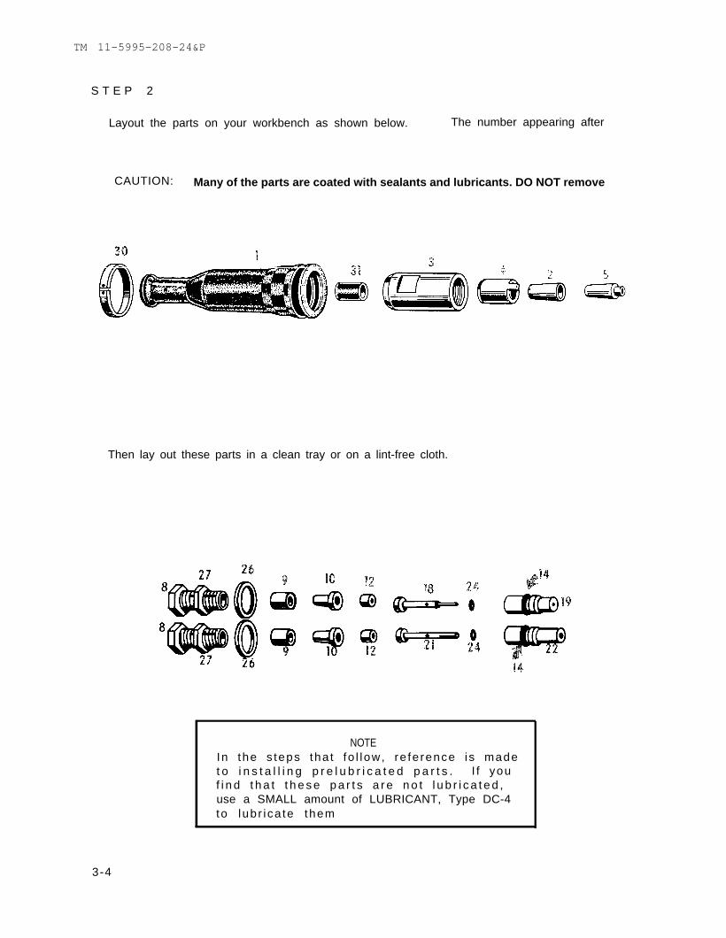
S T E P 2
Layout the parts on your workbench as shown below. The number appearing after
CAUTION: Many of the parts are coated with sealants and lubricants. DO NOT remove
Then lay out these parts in a clean tray or on a lint-free cloth.
NOTEIn the s teps tha t fo l low, re fe rence i s madet o i n s t a l l i n g p r e l u b r i c a t e d p a r t s . I f youf i n d t h a t t h e s e p a r t s a r e n o t l u b r i c a t e d ,use a SMALL amount of LUBRICANT, Type DC-4to lubr i ca te them
3-4
TM ll–5995–208–24&P
each part is the same number as the one listed in the packing list.
these materials from the parts or allow the parts to become dirty.
3-5

TM 11-5995-208-24&P
Place the proper ID tag (locally procured) over the end of the cable and
NOTE : Place a shortp iece o f sh r inkab letubing over end andt r e a t i n o r d e r t opro tec t boo t f romburrs on the supportb r a i d .
Place the 10 items onto the cable in the order and positions shown below,
andafter making sure every part is installed in the order and position shown, PUSH all the partsback, flush to the ID tag. This will give you room to work on the cut end as shown in thefollowing steps.
3-6

TM ll-5995-208-24&P
NOTE
The ID tag is in addition to the original tag on the cable. The
ID tag should include:
NOMENCLATURE
LENGTH
YEAR and MONTH
type of action-
OVH for OVERHAUL (repair of CX-1120/G) byreplacing CONNECTOR UG-1870/U
orFAB for FABRICATION (making 100 foot lengthsfrom 1/4 mile lengths)
orSCR for SCREENED (SCREENING by a desig-nated activity)
UNIT IDENTIFICATION (who did the OVH or FAB orSCR).
3-7

3-8
TM 11-5995-208-24&P

3-9
TM 11-5995-208-24&P

TM 11-5995-208-24&P
3-10
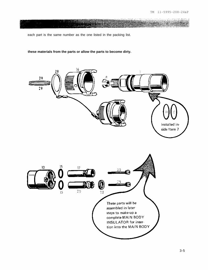
NOTE
Both INSULATION SLEEVES (29) should
be the EXACT SAME LENGTH.
MINIMUM length is 1 7/8 inches.
MAXIMUM length is 2 inches.
TM 11-5995-208-24&P
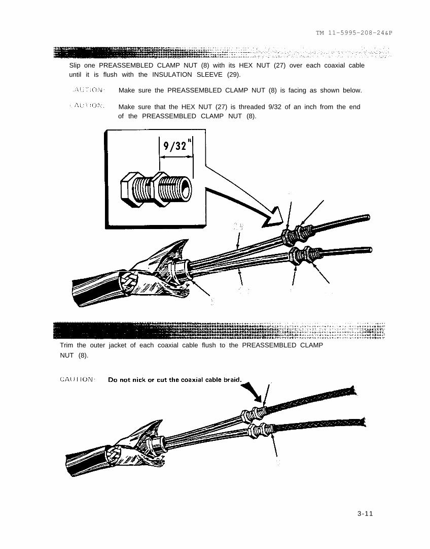
Slip one PREASSEMBLED CLAMP NUT (8) with its HEX NUT (27) over each coaxial cableuntil it is flush with the INSULATION SLEEVE (29).
Make sure the PREASSEMBLED CLAMP NUT (8) is facing as shown below.
Make sure that the HEX NUT (27) is threaded 9/32 of an inch from the endof the PREASSEMBLED CLAMP NUT (8).
Trim the outer jacket of each coaxial cable flush to the PREASSEMBLED CLAMP
NUT (8).
3-11

TM ll-5995-208-24&P
Slip one CLAMP BUSHING (9) over each coaxial cable. Push it flush against the PRE-ASSEMBLED CLAMP NUT (8).
CAUTION: Make sure the small opening of the CLAMP BUSHING (9) is against thePREASSEMBLED CLAMP NUT (8).
Comb back the braid on each coaxial cable using the small wire brush.
3-12
TM 11-5995-208-24&P
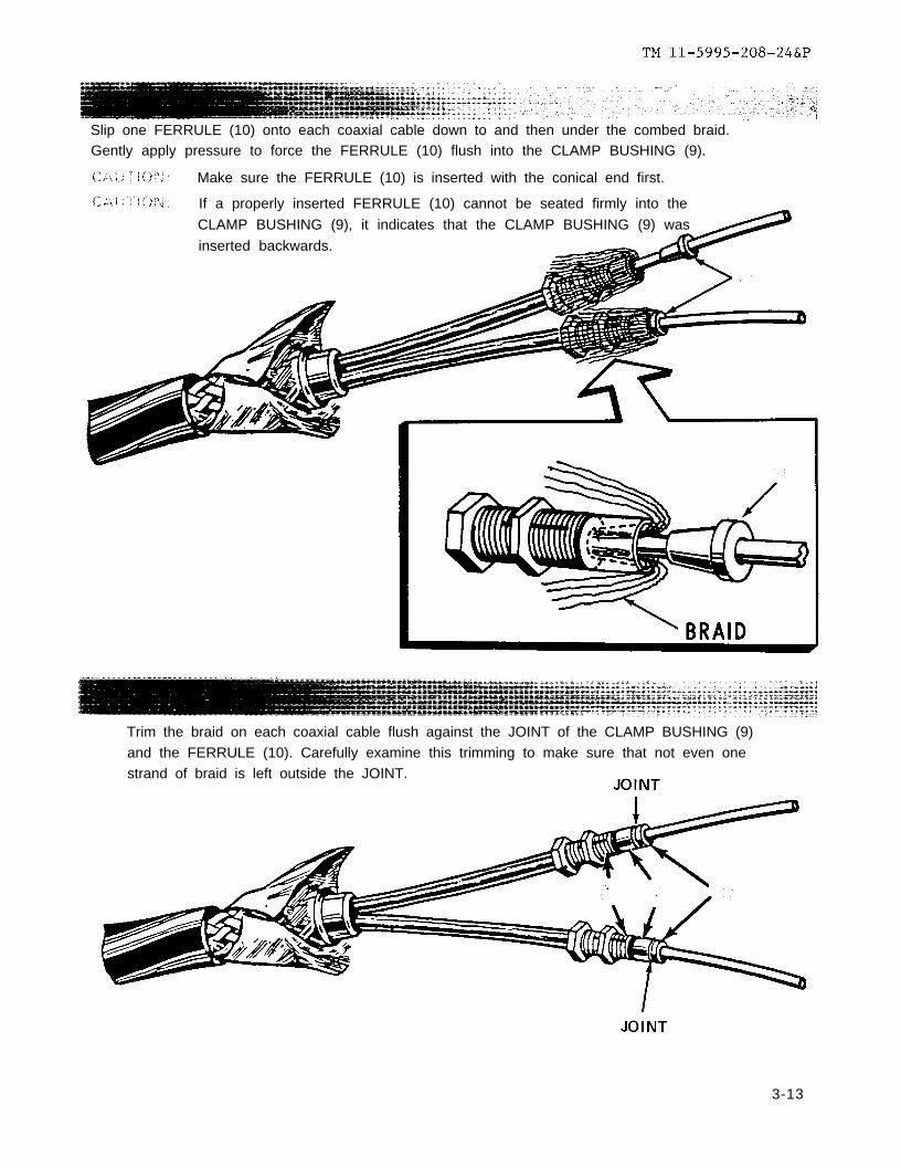
Slip one FERRULE (10) onto each coaxial cable down to and then under the combed braid.Gently apply pressure to force the FERRULE (10) flush into the CLAMP BUSHING (9).
Make sure the FERRULE (10) is inserted with the conical end first.
If a properly inserted FERRULE (10) cannot be seated firmly into the
CLAMP BUSHING (9), it indicates that the CLAMP BUSHING (9) was
inserted backwards.
Trim the braid on each coaxial cable flush against the JOINT of the CLAMP BUSHING (9)and the FERRULE (10). Carefully examine this trimming to make sure that not even onestrand of braid is left outside the JOINT.
3-13

TM 11-5995-208-24&P
Slip one REAR INSULATOR (12) over each coaxial cable until it is flush against theFERRULE (10).
Trim the dielectric of each coaxial cable flush to the REAR INSULATOR (12).
CAUTION: Do not nick or cut the strands of wire making up the center conductor for
3-14

TM 11-5995-208-24&P
Tin the center conductor of each coaxial cable
and
after cooling, trim to 7/16 of an inch.
3-15

TM ll-5995-208-24&P
Identify the coaxial cables. Use an ohmmeter to identify both ends of a coaxial cable.
NOTEYou are now preparing to install the MALE CONTACT andthe FEMALE CONTACT. In order for the TWIN COAX CA-
BLE (CX-11230/G) to work properly, one coaxial cable musthave a FEMALE CONTACT at one end and a MALE CON-TACT on the other end. The other coaxial cable must havethe opposite arrangement of contacts.
3-16

3-17
TM 11-5995-208-24&P

TM 11-5995-208-24&P
Set up a work jig as shown.
Use a discarded MAIN
NOTE
BODY INSULATOR (13). When it is
firmly held by the vise, you will be able to insert the contacts
into the insulator and hold them in a good working positionfor soldering.
NOTE
The discarded MAIN BODY INSULATOR isonly an aid. You will use a new MAIN BODY
INSULATOR in the later steps.
3-18
TM ll-5995-208-24&P
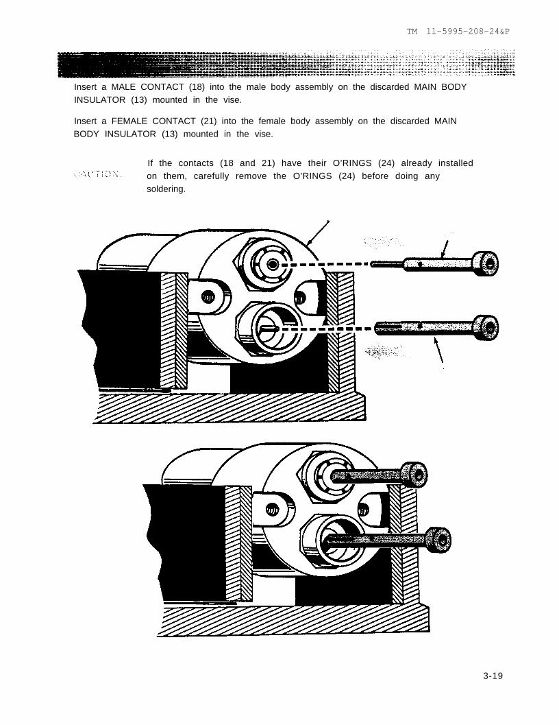
Insert a MALE CONTACT (18) into the male body assembly on the discarded MAIN BODYINSULATOR (13) mounted in the vise.
Insert a FEMALE CONTACT (21) into the female body assembly on the discarded MAINBODY INSULATOR (13) mounted in the vise.
If the contacts (18 and 21) have their O’RINGS (24) already installedon them, carefully remove the O’RINGS (24) before doing anysoldering.
3-19
TM ll-5995-208-24&P
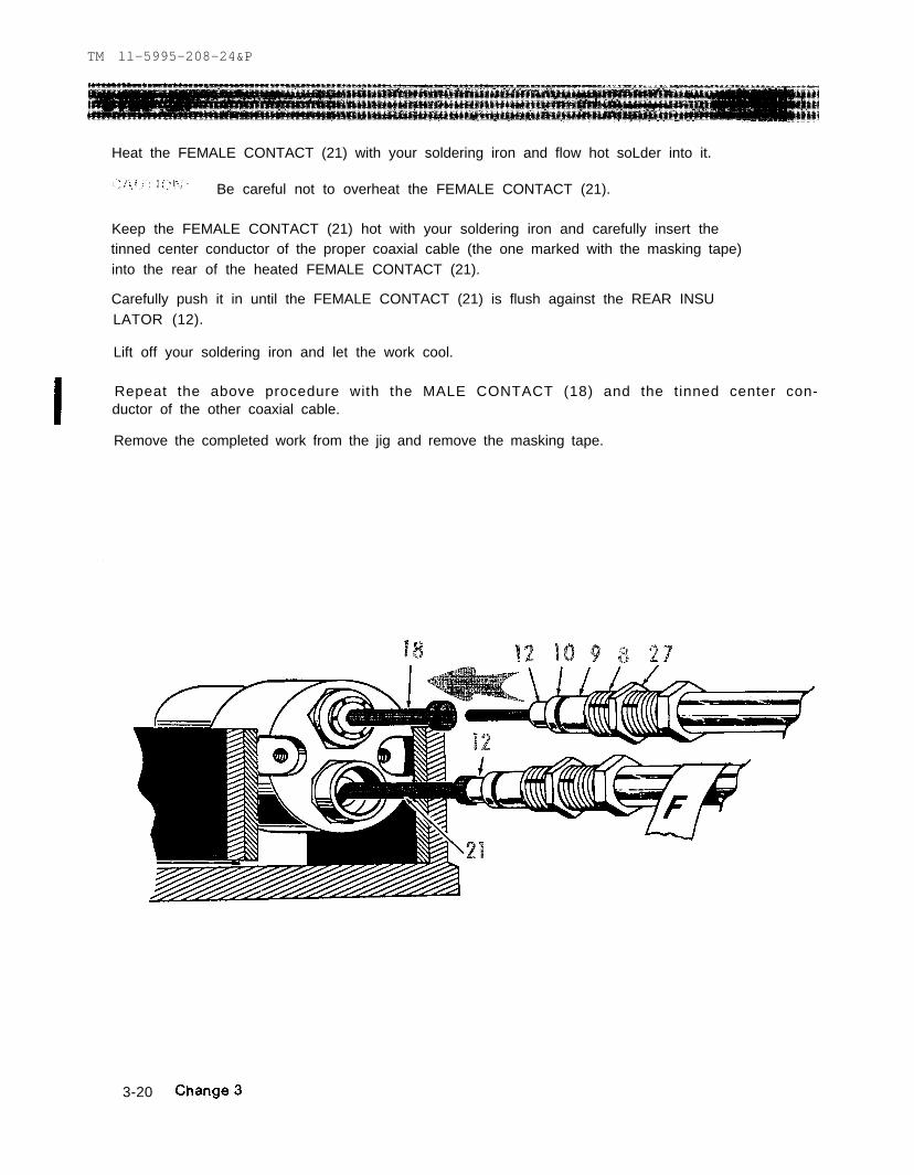
Heat the FEMALE CONTACT (21) with your soldering iron and flow hot soLder into it.
Be careful not to overheat the FEMALE CONTACT (21).
Keep the FEMALE CONTACT (21) hot with your soldering iron and carefully insert thetinned center conductor of the proper coaxial cable (the one marked with the masking tape)into the rear of the heated FEMALE CONTACT (21).
Carefully push it in until the FEMALE CONTACT (21) is flush against the REAR INSULATOR (12).
Lift off your soldering iron and let the work cool.
Repeat the above procedure with the MALE CONTACT (18) and the tinned center con-ductor of the other coaxial cable.
Remove the completed work from the jig and remove the masking tape.
3-20

TM ll–5995-208-24&P
Place a prelubricated O’RING (24) over the MALE RECONTACT (18) and move it down untilit is flush against the shoulder of the MALE CONTACT (18).
Do the same on the FEMALE CONTACT (21).
NOTE
Some parts packages may be received with theprelubricated O’RINGS (24) already installedover each contact. The O’RINGS should havebeen removed before soldering in previoussteps. You may also find extra O’RINGS (24)
in your parts package.
Change 1 3-21

TM 11-5995-208-24&P
Insert the FEMALE BODY ASSEMBLY (17) (with its prelubricated O’RINGS (15) in
place) into the new MAIN BODY INSULATOR (13).
Insert the MALE BODY ASSEMBLY (20) (with its prelubricated O’RING (15) in place)
into the new MAIN BODY INSULATOR (13).
NOTE
The design of the holes in the MAIN BODYINSULATOR (13) will prevent installing a
body assembly into the wrong hole.
3-22

3-23
TM 11-5995-208-24&P

TM 11-5995-208-24&P
Slide a WASHER (26) over each PREASSEMBLED CLAMP NUT (8).
NOTE
You are now ready to install the two coaxialcable assemblies into the MAIN BODY lNSU-LATOR.
* A
3-24

TM 11-5995-208-24&P
Screw in the coaxial cable male assembly (18, 19, 14, 10, 9, 26, 27 and 8) into the back ofthe female body assembly (17) on the MAIN BODY INSULATOR (13).
Make sure that the female body assembly (17) is properly
seated in the MAIN BODY INSULATOR (13).
Torque the PREASSEMBLED CLAMP NUT (8) to 5 inch pounds and then torque the HEXNUT (27) to 5 inch pounds.
Always torque the PREASSEMBLED CLAMP NUT (8) first.
Change 3 3-25

TM 11-5995-208-24&P
Screw in the coaxial cable female assembly (22, 14, 10, 9, 26, 27 and 8) into the back of the
male body assembly (20) on the MAIN BODY INSULATOR (13).
Make sure that the male body assembly (20) is properly seated in theCAUTION:MAIN BODY INSULATOR (13).
Torque the PREASSEMBLED CLAMP NUT (8) to 5 inch pounds and then torque the HEX
NUT (27) to 5 inch pounds.
CAUTION: Always torque the PREASSEMBLED CLAMP NUT (8) first.
3-26

TM ll-5995-208-24&P
Examine the MAIN BODY (7) and make sure that the O'RINGS (11) are in place.
Slide down the MAIN BODY (7) to receive the MAIN BODY INSULATOR (13).
Insert the SPLIT WASHER (6) onto the cable between the SUPPORT BRAID CONE (5) andthe MAIN BODY (7).
3-27
TM 11-5995-208-24&P
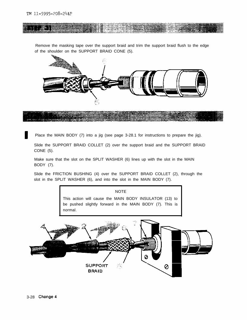
Remove the masking tape over the support braid and trim the support braid flush to the edgeof the shoulder on the SUPPORT BRAID CONE (5).
NOTE
This action will cause the MAIN BODY INSULATOR (13) tobe pushed slightly forward in the MAIN BODY (7). This is
normal.
Place the MAIN BODY (7) into a jig (see page 3-28.1 for instructions to prepare the jig).
Slide the SUPPORT BRAID COLLET (2) over the support braid and the SUPPORT BRAIDCONE (5).
Make sure that the slot on the SPLIT WASHER (6) lines up with the slot in the MAINBODY (7).
Slide the FRICTION BUSHING (4) over the SUPPORT BRAID COLLET (2), through theslot in the SPLIT WASHER (6), and into the slot in the MAIN BODY (7).
3-28

be fabricated from 1/2” thick aluminum or other material ofthe MAIN BODY (7).
Jig shouldto support
Mount the jig to a work bench or in a vise to hold it in place.
Fabricate the jig to the dimensions shown in the illustration below.
TM ll-5995-208-24&P
sufficient strength
1. Slot to hold MAIN BODY (7) should be at least 1-1/2” at the center point of curve.2. Mounting holes should be drilled to 3/16”.
3-28.1/(3-28.2 blank)


TM 11-5995-208-24&P
Slide the CLAMP NUT (3) over the FRICTION BUSHING (4) and screw it handtight overthe MAIN BODY (7).
Torque the CLAMP NUT (3) to 100 inch pounds.
Complete the installation of the MAIN BODY INSULATOR (13) into the MAIN BODY (7).
Push the MAIN BODY INSULATOR (13) back and install the two SCREWS (25).
Tighten down the two SCREWS (25) to 5 inch pounds.\
NOTE
Each SCREW (25) has a factory installed O’RING on it and when prop-
erly tightened, the MAIN BODY INSULATOR (13) is approximatelyinch below the face of the MAIN BODY (7).
By hand, insert the NON-METALIC WASHER (23) over the MALE BODY ASSEMBLY (20).
Change 1 3-29

TM 11-5995-208-24&P
Slide down the COUPLING NUT (16) and CAP ASSEMBLY (28) over the MAIN BODY (7).
3-30

TM ll-5995-208-24&P
Slide the SLEEVE (31) flush against the CLAMP NUT (3).
Apply SILICONE compound, MIL-A-46106A, TYPE 1, around the SLEEVE (31), the twogrooves on the MAIN BODY (7) and on the front grooves inside the SEALING BOOT (1).
3-31

TM 11-5995-208-24&P
Slide down the SEALING BOOT (1) (with its RING (30) in place) over the two grooves on
the MAIN BODY (7).
3-32

paragraph 3-10
Section VI.
Table 2-1
TM ll-5995-208-24&P
3-7. GENERAL
All cables returned to general support for action and all repaired cables should undergo thefollowing:
a.b.
3-8.
a.b.
3-9.
Setup
Change 5 3-33

TM 11-5995-208-24&P
3-10. INSULATION BREAKDOWN/LEAKAGE TEST PROCEDURES
This task covers:a. Setupb. Testing
INITIAL SETUP
Test Equipment:Insulation BreakdownTest Set (AN/GSM-6)
Special Tools:Tool Kit TK-100/G
Materials/Parts:Twin Coax Cable stubwith CONNECTOR (UG-1870/U).6 feet of bare copperwire (single conductor, 18AWG).
S T E P 1
Setup the Insulation Breakdown Test
3-34
Personnel Required:2
Special Environmental Conditions
Set (AN/GSM-6) but DO NOT TURN IT ON.
test point on the output cable, the “hot” side of the AN//GSM-6.
test point for the other side of the output cable, connected by a “GUARD WIRE” (barecopper, single conductor, 18 AWG).
GROUND for the AN/GSM-6, IT MUST BE CONNECTED TO THE GROUND CLAMP(test pointL in STEP 2).
Change 5

TM 11-5995-208-24&P
Setup a tes t cab le s tub . Use known good components. Th is tes t cab le s tub shou ldbe s e c u r e d to p reven t acc iden ta l touch ing o f l eads wh i le tes t ing .
D = test point on the tinned center conductor of the first coaxial cable.E = test point on the insulation of the first coaxial cable.F = test point on the braid of the first coaxial cable.
G = t es t po in t on the t i nned cen te r conduc to r o f the second coax ia l cab le .H = t e s t p o i n t o n t h e i n s u l a t i o n o f t h e s e c o n d c o a x i a l c a b l e .I = tes t po in t on the b ra id o f the second coax ia l cab le .
J = tes t po in t on the ou te r suppor t b ra id o f the tw in coax ia l cab le .
K = connect ion for 100 foot or mi le lengths of TWIN COAXIAL CABLE (CX-11230/G),or TWIN COAX ADAPTER CABLE (CX-10734/G) undergoing test.
L = GROUND CLAMP, connected to a rod or strap which is connected to the approvedg r o u n d f o r t h e w o r k a r e a . T e s t p o i n t a n d t e s t p o i n t connect to groundth rough the rod o r s t rap .
3-35
TM 11-6625-273-12 paragraph 17
TM ll-5995-208-24&P
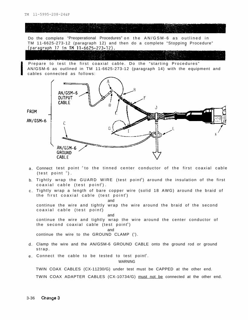
Do the complete “Preoperational Procedures” o n t h e A N / G S M - 6 a s o u t l i n e d i nTM 11-6625-273-12 (paragraph 12) and then do a complete “Stopping Procedure”
P r e p a r e t o t e s t t h e f i r s t c o a x i a l c a b l e . D o t h e “ s t a r t i n g P r o c e d u r e s ”AN/GSM-6 as out l ined in TM 11-6625-273-12 (paragraph 14) wi th the equipment andcab les connec ted as fo l l ows :
a .
b.
c .
d .
e .
Connect t e s t p o i n t A t o t h e t i n n e d c e n t e r c o n d u c t o r o f t h e f i r s t c o a x i a l c a b l e( t e s t p o i n t D ) .
T i g h t l y w r a p t h e G U A R D W I R E ( t e s t p o i n tB ) a round the insu la t ion o f the f i r s tc o a x i a l c a b l e ( t e s t p o i n tE ) .T igh t l y wrap a leng th o f ba re copper w i re (so l id 18 AWG) a round the b ra id o ft h e f i r s t c o a x i a l c a b l e ( t e s t p o i n tF )
andcon t inue the w i re and t igh t l y wrap the w i re a round the b ra id o f the secondc o a x i a l c a b l e ( t e s t p o i n tI)
andcon t inue the w i re and t igh t l y wrap the w i re a round the cen te r conduc to r o ft h e s e c o n d c o a x i a l c a b l e ( t e s t p o i n tG )
andcontinue the wire to the GROUND CLAMP ( L) .
Clamp the wire and the AN/GSM-6 GROUND CABLE onto the ground rod or grounds t r a p .
Connec t the cab le to be tes ted to tes t po in tK .
WARNING
TWIN COAX CABLES (CX-11230/G) under test must be CAPPED at the other end.
TWIN COAX ADAPTER CABLES (CX-10734/G) must not be connected at the other end.
3-36

TM 11-5995-208-24&P
D o t h e “ W i t h s t a n d T e s t ” o n t h e f i r s t c o a x i a l c a b l e . F o l l o w t h e p r o c e d u r e s o u t -l i ned in TM 11-6625-273-12 (paragraph 15) us ing the fo l l ow ing se t t i ngs andprocedures:
a.
b.
apply 2.500 volts ( 2 . 5 K I L O V O L T S ) .
a p p l y t h i s v o l t a g e f o r
CAUTION: If the DCOVERLOAD indicator on the AN/GSM-6 lights up - STOP THETEST because you have a BAD CABLE.
c . During the ONE MINUTE you are applying the 2,500 vol ts, observe theMICROAMPERES meter. I f the leakage cur ren t reaches 50 microamperes, youhave a bad cable, STOP THE TEST.
d . I f t h e f i r s t c o a x i a l c a b l e p a s s e s t h e t e s t v o l t a g e f o r o n e m i n u t e , s t o pa p p l y i n g t h e v o l t a g e a n d d o a c o m p l e t e "Stopping Procedure" as outlined inTM 11-6625-273-12(paragraph 17).
CAUTION: Whenever you stop the test, you must always do a complete“S topp ing Procedure ” . T h i s w i l l a l l o w y o u t o s a f e l y p r o c e e d w i t ho t h e r s t e p s .
3-37

TM 11-5995-208-24&P
Prepare to test the second coaxial cable. Do the “Starting Procedures” on theAN/GSM-6 as outlined in TM 11-6625-273-12 (paragraph 14) with the equipment andcables connected as follows:
a.
b.
c.
d.
Connect test point A to the tinned center conductor of the second coaxial cable(test point G).
Tightly wrap the GUARD WIRE (test point B) aroundcoaxial cable (test point H).
Tightly wrap a length of bare copperware (solid 1the second coaxial cable (test point I).
andcontinue the wire and tightly wrap the wire aroundcoaxial cable (test point F).
and
the insulation of the second
8 AWG) around the braid of
the braid of the first
continue the wire and tightly wrap the wire around the center conductor ofthe first coaxial cable (test point D).
andcontinue the wire to the GROUND CLAMP (L).
Clamp the wire and the AN/GSM-6 GROUND CABLE onto the ground rod or groundstrap.
3-38

TM 11-5995-208-24&P
D O the “withstand Test” on the second coaxial cable. Follow the procedures
outlined in TM 11-6625-273-12 (paragraph 15) using the following settings andprocedures:
a. apply 2,500 volts (2.5 KILOVOLTS). W A R N I N GBE CAREFUL
b. apply this voltage for ONE MINUTE.
CAUTION: If the DC OVERLOAD indicator on the AN/GSM-6 lights up - STOP THE
TEST because you have a BAD CABLE.
c. During the ONE MINUTE you are applying the 2,500 volts, observe theMICROAMPERES meter. If the leakage current reaches 50 microampere, youhave a bad cable, STOP THE TEST.
d. If the second coaxial cable passes the test voltage for one minute, stop apply-ing the voltage and do a complete "Stopping Procedure" as outlined in TM11-6625-273-12 (paragraph 17).
CAUTION: Whenever you stop the test, you must always do a complete
“Stopping Procedure”.
Change 5 3-39

TM 11-5995-208-24&P
3 - 1 1 . RESISTANCE CHECK
All ¼ mile lengths of Twin Coaxial Cable (CX-11230/G) which have passed the InsulationBreakdown/Leakage Test of paragraph 3-9 shall undergo a resistance check. UseResistance Bridge ZM-4(*)/U. Follow the instructions of paragraph 14 in TM 11-2019. Thefollowing data apply:
a.
b.
NOTE
When measuring the resistance of cable assemblies that are measuredless than ¼ mile (1320 feet) allow 1 ohm resistance for every 52.8 feet ofcable (i.e. - a 1000 foot length of cable should not measure more than18.95 ohms).
The dc resistance of the center conductor in EACH coaxial cable shall not exceed25 ohms for a full ¼ mile (1320 foot) cable assembly.
The dc resistance of the shield in EACH coaxial cable shall not exceed 8½ ohms.
NOTES
Any cable having a higher resistance shall be considered defective.Further action on these defective cables shall be determined by your
supervisor.
Remember, even if a cable passes all of the tests, it may not work wella system.
in
A final dynamic test is desirable. It may be possible for your supervisor toarrange for a dynamic test using MUX equipment.
3-40 Change 5

T M 1 1 - 5 9 9 5 - 2 0 8 - 2 4 & P
APPENDIX A
REFERENCES
CTA 50-970
FM 24-20
SB 38-100
SB 708-42
SF 5180-91-CL-R13
SC 5180-91-CL-S21
TB SIG 222
TB 746-10
TM 11-2019
TM 11-5805-367-12
TM 11-5805-367-35/4
TM 11-5805-383-12
TM 11-5995-208-10
Expendable Items (Except: Medical, Class V, Repair Parts andHeraldic Items)
Field Wire and Field Cable Techniques
Preservation, Packing and Marking Materials, Supplies, andEquipment used by the Army
Federal Supply Code for Manufacturers; United States and Canada-- Code to Name (H4-2) (GSA-FSS-H4-2)
Tool Kit, Electronic Equipment TK-101/G (NSN 5180-00-064-5178)
Tool Kit, Electronic Equipment, TK-100/G (NSN 5180-00-605-0079)
Solder and Soldering
Field Instructions for Painting and Preserving Electronics CommandEquipment
Test Sets 1-49, 1-49-A, and 1-49-B and Resistance Bridges ZM-4A/Uand ZM-4B/U
Operator ’s and Organizat ional Maintenance Manual; Mult ip lexerTD-202/U (NSN 5805-00-884-2176), TD-203/U (NSN 5805-00-884-2177),TD-204/U (NSN 5805-00-900-8200), TD-352/U (NSN 5805-00-900-8199),and TD-353/U (NSN 5805-00-985-9153); Restorers, Pulse FormTD-206/G (NSN 5805-00-868-8078) and TD-206B/G(NSN 5805-01-020-2251) and Converters, Telephone SignalCV-1548/G (NSN 5805-00-069-8795) and CV-1548A/G(NSN 5805-00-069-8795)
Direct Support, General Support, and Depot Maintenance Manual,Restorers, Pulse Form TD-206/G
Operator ’s and Organizat ional Maintenance Manual Mult ip lexer,TD-754/G (NSN 5820-00-930-8078)
Operator’s Manual for Cable Assembly, Special Purpose, ElectricalCX-11230/G (¼ mile) (NSN 5995-00-133-9126), CX-11230/G(100 foot) (NSN 5995-00-133-9127), CX-11230A/G (1320 foot)(NSN 5995-01-121-6623), CX-11230A/G (100 foot)(NSN 5995-01-125-6781) and CX-10734/G (NSN 5995-00-133-9125)
C h a n g e 5 A-1
TM 11-5995-208-24&P
APPENDIX A
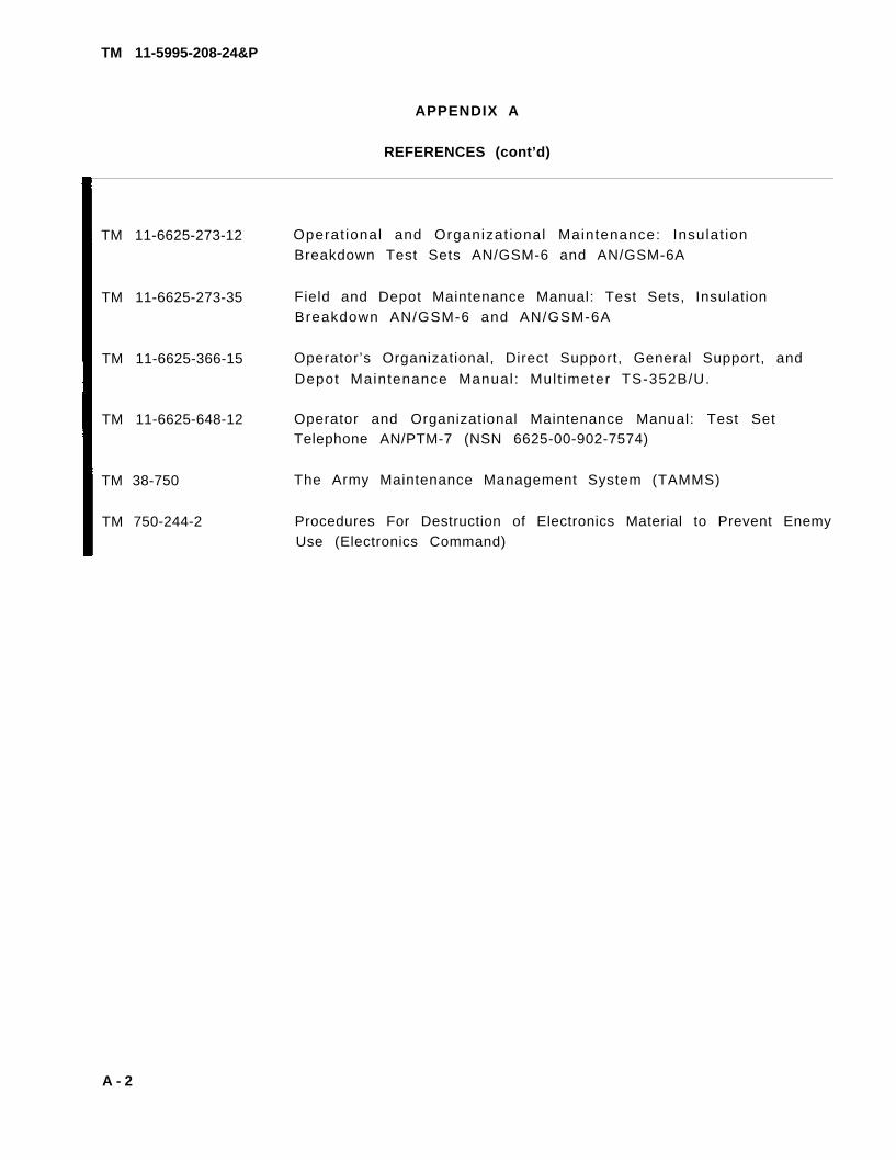
REFERENCES (cont’d)
TM 11-6625-273-12 Operat ional and Organizat ional Maintenance: Insulat ionBreakdown Test Sets AN/GSM-6 and AN/GSM-6A
TM 11-6625-273-35 Field and Depot Maintenance Manual: Test Sets, InsulationBreakdown AN/GSM-6 and AN/GSM-6A
TM 11-6625-366-15 Operator’s Organizational, Direct Support, General Support, and
Depot Maintenance Manual: Mult imeter TS-352B/U.
TM 11-6625-648-12 Operator and Organizational Maintenance Manual: Test SetTelephone AN/PTM-7 (NSN 6625-00-902-7574)
TM 38-750 The Army Maintenance Management System (TAMMS)
TM 750-244-2 Procedures For Destruction of Electronics Material to Prevent EnemyUse (Electronics Command)
A - 2

TM 11-5995-208-24&P
APPENDIX B
MAINTENANCE ALLOCATION
Section I. INTRODUCTION
B-1. General
This appendix provides a summary of the maintenance operations for CX-11230/G andCX-10734/G. It authorizes categories of maintenance for specific maintenancefunctions on repairable items and components and the tools and equipment requiredto perform each function. This appendix may be used as an aid in planning main-tenance operations.
B-2. Maintenance Function
Maintenance functions will be limited to and defined as follows:
a. Inspection. To determine the serviceability of an item by comparing itsphysical, mechanical, and/or electrical characteristics with established standardsthrough examination.
b. Test. To verify serviceability and to detect incipient failure by measur-ing–the mechanical or electrical characteristics of an item and comparing thosecharacteristics with prescribed standards.
c. Service. Operations required periodically to keep an item in properoperating condition, i.e., to clean (decontaminate), to preserve, to drain, topaint, or to replenish fuel, lubricants, hydraulic fluids, or compressed airsupplies.
d. Adjust. To maintain, within prescribed limits, by bringing into proper orexact position, or by setting the operating characteristics to the specifiedparameters.
e . A l i g n . To adjust specified variable elements of an item to bring aboutoptimum or desired performance.
f. Calibrate. To determine and cause corrections to be made or to be adjustedon instruments or test measuring and diagnostic equipments used in precisionmeasurement, Consists of comparisons of two instruments, one of which is acertified standard of known accuracy, to detect and adjust any discrepancy in theaccuracy of the instrument being compared.
g . Install. The act of emplacing, seating, or fixing into position an item,part, module (component or assembly) in a manner to allow the proper functioningof the equipment or system.
Change 1 B-1

TM 11-5995-208-24&P
h. Replace. The act of substitutior module component or assembly) for
ng a serviceable like type part, subassembly,an unserviceable counterpart.
i. Repair. The application of maintenance services (inspect, test, service.adjust, align, calibrate, replace) or other maintenance actions (welding, grinding,riveting, straightening, facing, remachining, or resurfacing) to restore service-ability-to an item by correcting specific damage, fault, malfunction, or failurein a part, subassembly, module (component or assembly), end item, or system.
j. Overhaul. That maintenance effort (service/action) necessary to restorean item to a completely serviceable/operational condition as prescribed by main-tenance standards (i.e., DMWR) in appropriate technical publications. Overhaulis normally the highest degree of maintenance performed by the Army. Overhauldoes not normally return an item to like new condition.
k. Rebuild. Consists of those services/actions necessary for the restorationof unserviceable equipment to a like new condition in accordance with originalmanufacturing standards. Rebuild is the highest degree of materiel maintenanceapplied to Army equipment. The rebuild operation includes the act of returningto zero those age measurements (hours, miles, etc.) considered in classifyingArmy equipments/components.
B-3. Column Entries
a. Column 1, Group Number. Column 1 lists group numbers, the purpose of whichis to identify components, assemblies, subassemblies, and modules with the nexthigher assembly.
b. Column 2, Component/Assembly. Column 2 contains the noun names of compo-nents, assemblies, subassemblies, and modules for which maintenance is authorized.
c. Column 3, Maintenance Functions. Column 3 lists the functions to be per-formed on the item listed in column 2. When items are listed without maintenancefunctions, it is solely for purpose of having the group numbers in the MAC andRPSTL coincide.
d. Column 4, Maintenance Category. Column 4 specifies, by the listing of a“work time” figure in the appropriate subcolumn(s), the lowest level of mainte-nance authorized to perform the function listed in column 3. This figure repre-sents the active time required to perform that maintenance function at the in-dicated category of maintenance. If the number or complexity of the tasks withinthe listed maintenance function vary at different maintenance categories, appro-priate “work time” figures will be shown for each category. The number of task-hours specified by the “work time” figure represents the average time required torestore an item (assembly, subassembly, component, module, end item or system) toa serviceable condition under typical field operating conditions. This time in-cludes preparation time, troubleshooting time, and quality assurance/qualitycontrol time in addition to the time required to perform the specific tasksidentified for the maintenance functions authorized in the maintenance allocationchart. Subcolumns of column 4 are as follows:
B-2 Change 1

TM 11-5995-208-24&P
C -O -F -H -D -
Operator/CrewOrganizationalDirect SupportGeneral SupportDepot
e. Column 5, Tools and Equipment. Column 5 specifies by code, those commontool sets (not individual tools) and special tools, test, and support equipmentrequired to perform the designated function.
f. Column 6, Remarks. Column 6 contains an alphabetic code which leads tothe remark in section IV, Remarks, which is pertinent to the item opposite theparticular code.
B-4. Tool and Test Equipment Requirements (Sect. III).
a. Tool or Test Equipment Reference Code. The numbers in this column coin-cide with the numbers used in the tools and equipment column of the MAC. Thenumbers indicate the applicable tool or test equipment for the maintenancefunctions.
b. Maintenance Category. The codes in this column indicate the maintenancecategory allocated the tool or test equipment.
c. Nomenclature. This column lists the noun name and nomenclature of thetools and test equipment required to perform the maintenance functions.
d. National/NATO Stock Number. This column lists the National/NATO stocknumber of the specific tool or test equipment.
e. Tool Number. This column lists the manufacturer’s part number of thetool followed by the Federal Supply Code for manufacturers (5-digit) in paren-theses.
B-5 Remarks (Sect. IV).
a. Reference Code. This code refers to the appropriate item in section II,column 6.
b. Remarks. This column provides the required explanatory informationnecessary to clarify items appearing in section II.
Change 1 B-3

T M 1 1 - 5 9 9 5 - 2 0 8 - 2 4 & P
S E C T I O N I I MAINTENANCE ALLOCATION CHARTFOR
CABLE ASSEMBLY, SPECIAL PURPOSE CX-11230/G AND CABLE ASSEMBLY, AOAPTER CX-10734/G
(1)G R O U P
N U M B E R
01
0 2
03
(2)COMPONENT ASSEMBLY
‘ABLE ASSEMBLY, SPECIAL PURPOSE CX-11230/G
@LE ASSEMBLY, SPECIAL PURPOSE CX-11230/G100 FEET)
ABLE ASSEMBLY, ADAPTER CX-10734/Ga B
B-4 Change 2

TM11-5995-208-24&PSECTION III TOOL AND TEST EQUIPMENT REQUIREMENTS
FORCABLE ASSEMBLY, SPECIAL PURPOSE CX-11230/G AND CABLE ASSEMBLY, ADAPTER CS-10734/G
TOOLS OR TEST EQUIPMENT MAINTENANCE NOMENCLATURE NATIONAL/NATO TOOL NUMBER REF CODE CATEGORY STOCK NUMBER
1 C,O TEST SET, TELEPHONE AN/PTM-7 6625-00-902-7574
2 H TEST SET, INSULATION BREAKDOWN AN/GSM-6 6625-00-542-1331
3 H RESISTANCE BRIDGE ZM-4B/U 6625-00-500-0937
4 O TOOL KIT, ELECTRONIC EQUIPMENT TK-101/G 5180-00-064-5178
5 H TOOL KIT, ELECTRONIC EQUIPMENT TK-105/G 5180-00-610-8177
6 H TORQUE WRENCH 5120-00-230-6380
7 H WRENCH, CROWFOOT 3/8 INCH 5120-00-181-6784
8 H WRENCH, CROWFOOT 15/16 INCH 5120-00-184-8403
9 H TORQUE SCREWDRIVER 5120-00-568-4742
10 H WIRE BRUSH 7510-00-559-9833
11 H MULTIMETER-TS-352B/U OR MULTIMETER AN/USM-223 6625-00-553-0142
12 H TOOL KIT, ELECTRONIC EQUIPMENT TK-100/G 5180-00-605-0079
CHANGE 1 B-5

TM 11-5995-208-24&PSECTION IV. REMARKS
REFERENCECODE
REMARKS
A OPERATIONAL LOOP-BACK TEST.
B REPLACE CONNECTOR CAP.
C REPAIR TO BE PERFORMED BY HOLDER OF MOS 26L.
B-6 Change 2

TM 11-5995-208-24&P
APPENDIX C
ORGANIZATIONAL, DIRECT SUPPORT, AND GENERAL SUPPORT
MAINTENANCE REPAIR PARTS AND SPECIAL TOOLS LIST
(INCLUDING DEPOT MAINTENANCE REPAIR PARTS AND SPECIAL TOOLS)
Section I. INTRODUCTION
C-1. Scope
This appendix lists spares and repair parts; special tools; special test, meas-urement, and diagnostic equipment (TMDE), and other special support equipmentrequired for performance of organizational, direct support, and general supportmaintenance of the CX-11230/G and CX-10734/G. It authorizes the requisitioningand issue of spares and repair parts as indicated by the source and maintenancecodes.
C-2. General
This Repair Parts and Special Tools List is divided into the following sections:
a. Section II. Repair Parts List. A list of spares and repair parts author-ized for use in the performance of maintenance. The list also includes partswhich must be removed for replacement of the authorized parts. Parts lists arecomposed of functional groups in numeric sequence, with the parts in each grouplisted in figure and item number sequence.
b. Section III. Special Tools List. Not applicable.—
c. Section IV. National Stock Number and Part Number Index. A list, inNational item identification number (NIIN) sequence, of all National stock numbers(NSN) appearing in the listings, followed by a list, in alphameric sequence, ofall parts numbers appearing in the listings. National stock numbers and partnumbers are cross-referenced to each illustration figure and item number appear-ance.
C-3. Explanation of Columns
Illustration. This column is divided as follows:a.
(1) Figure number. Indicates the figure number of the illustration onwhich the item is shown.
(2) Item number. The number used to identify item called out in the illus-tration.
Change 1 C-1
TM 11-5995-208-24&P
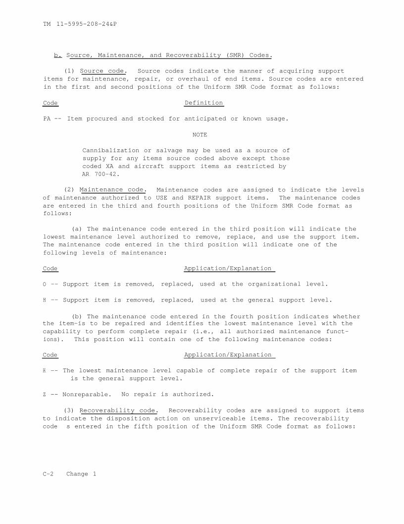
b. Source, Maintenance, and Recoverability (SMR) Codes.
(1) Source code. Source codes indicate the manner of acquiring supportitems for maintenance, repair, or overhaul of end items. Source codes are enteredin the first and second positions of the Uniform SMR Code format as follows:
Code Definition
PA -- Item procured and stocked for anticipated or known usage.
NOTE
Cannibalization or salvage may be used as a source ofsupply for any items source coded above except thosecoded XA and aircraft support items as restricted byAR 700-42.
(2) Maintenance code. Maintenance codes are assigned to indicate the levelsof maintenance authorized to USE and REPAIR support items. The maintenance codesare entered in the third and fourth positions of the Uniform SMR Code format asfollows:
(a) The maintenance code entered in the third position will indicate thelowest maintenance level authorized to remove, replace, and use the support item.The maintenance code entered in the third position will indicate one of thefollowing levels of maintenance:
Code Application/Explanation
O -- Support item is removed, replaced, used at the organizational level.
H -- Support item is removed, replaced, used at the general support level.
(b) The maintenance code entered in the fourth position indicates whetherthe item–is to be repaired and identifies the lowest maintenance level with thecapability to perform complete repair (i.e., all authorized maintenance funct-ions). This position will contain one of the following maintenance codes:
Code Application/Explanation
H -- The lowest maintenance level capable of complete repair of the support itemis the general support level.
Z -- Nonreparable. No repair is authorized.
(3) Recoverability code. Recoverability codes are assigned to support itemsto indicate the disposition action on unserviceable items. The recoverabilitycode s entered in the fifth position of the Uniform SMR Code format as follows:
C-2 Change 1
TM 11-5995-208-24&P
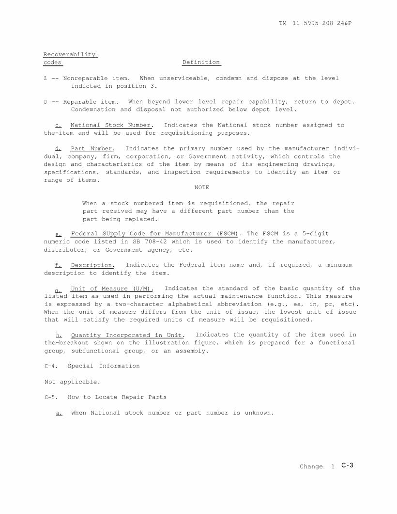
Recoverabilitycodes Definition
Z -- Nonreparable item. When unserviceable, condemn and dispose at the levelindicted in position 3.
D -- Reparable item. When beyond lower level repair capability, return to depot.Condemnation and disposal not authorized below depot level.
c. National Stock Number. Indicates the National stock number assigned tothe–item and will be used for requisitioning purposes.
d. Part Number. Indicates the primary number used by the manufacturer indivi-dual, company, firm, corporation, or Government activity, which controls thedesign and characteristics of the item by means of its engineering drawings,specifications, standards, and inspection requirements to identify an item orrange of items.
NOTE
When a stock numbered item is requisitioned, the repairpart received may have a different part number than thepart being replaced.
e. Federal SUpply Code for Manufacturer (FSCM). The FSCM is a 5-digitnumeric code listed in SB 708-42 which is used to identify the manufacturer,distributor, or Government agency, etc.
f. Description. Indicates the Federal item name and, if required, a minumumdescription to identify the item.
g. Unit of Measure (U/M). Indicates the standard of the basic quantity of thelisted item as used in performing the actual maintenance function. This measureis expressed by a two-character alphabetical abbreviation (e.g., ea, in, pr, etc).When the unit of measure differs from the unit of issue, the lowest unit of issuethat will satisfy the required units of measure will be requisitioned.
h. Quantity Incorporated in Unit. Indicates the quantity of the item used inthe–breakout shown on the illustration figure, which is prepared for a functionalgroup, subfunctional group, or an assembly.
C-4. Special Information
Not applicable.
C-5. How to Locate Repair Parts
When National stock number or part number is unknown.a.
Change 1 C-3

TM 11-5995-208-24&P
(1) First. Using the table of contents, determine the functional groupwithin which item belongs. This is necessary since illustrations are preparedfor functional groups and listings are divided into the same groups.
(2) Second. Find the illustration covering the functional group to whichthe item belongs.
(3) Third. Identify the item on the illustration and note the illustrationfigure and item number of the item.
(4) Fourth. Using the Repair Parts Listingnoted on the illustration.
b. When National stock number or part number
find the figure and item number
is known.
(1) First. Using the Index of National Stock Numbers and Part Numbers, findthe pertinent National stock number or part number. This index is in NIINsequence followed by a list of part numbers in alphameric sequence, cross-referenced to the illustration figure and item number.
(2) Second. After finding the figure and item number, locate the figureand item number in the repair parts list.
C-6. Abbreviations
Not applicable.
C-4 Change 1

TM 11-5995-208-24&P
Figure C-1. Cable Assembly, Special Purpose, Electrical CX-11230/G(1/4 Mile and 100 Feet) and Cable Assembly, Adapter CX-10734/G.
Change 1 C-5

TM11-5995-208-24&P SECTION II. REPAIR PARTS LIST(1) (2) (3) (4) (5) (6) (7) (8)ILLUSTRATION(a) (b)
QTYNATIONAL USABLE INC
FIG. ITEM SMR STOCK PART ON INNO. NO. CODE NUMBER NUMBER FSCM DESCRIPTION CODE U/M UNIT
GROUP 01 CABLE ASSEMBLY, SPECIAL PURPOSE,ELECTRICAL CX-11230/G (1/4 MILE)
C-1 1 PAOHD* 5995-00-133-9126 CX-11230/G 80063 CABLE ASSEMBLY, SPECIAL PURPOSE, ELECTRICAL EA 1(1/4 MILE)
C-1 2 PAOZZ 8130-00-964-9014 RC-453/G 80063 REEL, CABLE EA 1
OR
C-1 3 PAOZZ 8130-00-263-8646 DR-15B 80063 REEL, CABLE EA 1
C-1 4 PAHZZ 5935-00-179-4688 UG-1870/U 80063 CONNECTOR, PLUG, ELECTRICAL EA 2
C-1 5 PAOZZ 5999-00-136-9040 SC-C-388423 80063 CAP, ELECTRICAL EA 2
GROUP 02 CABLE ASSEMBLY, SPECIAL PURPOSE,ELECTRICAL CX-11230/G (100 FEET)
C-1 4 PAHZZ 5935-00-179-4688 UG-1870/U 80063 CONNECTOR, PLUG, ELECTRICAL EA 2
C-1 5 PAOZZ 5999-00-136-9040 SC-C-388423 80063 CAP, ELECTRICAL EA 2
C-1 6 PAOHD* 5995-00-133-9127 CX-11230/G 80063 CABLE ASSEMBLY, SPECIAL PURPOSE, ELECTRICAL EA 1(100 FEET)
C-1 7 PAOZZ 8130-00-656-1090 RC-435/U 80063 REEL, CABLE EA 1
GROUP 03 CABLE ASSEMBLY, ADAPTER CX-10734/G
C-1 5 PAOZZ 5999-00-136-9040 SC-C-388423 80063 CAP, ELECTRICAL EA 1
C-1 8 PAOOZ 5995-00-133-9125 CX-10734/G 80063 CABLE ASSEMBLY, ADAPTER EA 1
C-6 CHANGE 1

TM11-5995-208-24&P
SECTION IV. NATIONAL STOCK NUMBER AND PART NUMBER INDEXFIG. ITEM FIG. ITEM
STOCK NUMBER NO. NO. STOCK NUMBER NO. NO.
5995-00-133-9125 C-1 8 5935-00-179-4688 C-1 45995-00-133-9126 C-1 1 5935-00-179-4688 C-1 45995-00-133-9127 C-1 6 8130-00-263-8646 C-1 35999-00-136-9040 C-1 5 8130-00-656-1090 C-1 75999-00-136-9040 C-1 5 8130-00-964-9014 C-1 25999-00-136-9040 C-1 5
FIG. ITEM FIG. ITEMPART NUMBER FSCM NO. NO. PART NUMBER FSCM NO. NO.
CX-10734/G 80063 C-1 8 RC-453/G 80063 C-1 2CX-11230/G(100 FEET)80063 C-1 6 SC-C-388423 80063 C-1 5CX-11230/G(1/4 MILE)80063 C-1 1 SC-C-388423 80063 C-1 5DR-15B 80063 C-1 3 SC-C-388423 80063 C-1 5RC-435/U 80063 C-1 7 UG-1870/U 80063 C-1 4
UG-1870/U 80063 C-1 4
CHANGE 1 C-7/(C-8 BLAN


TM 11-5995-208-24&P
APPENDIX D
EXPENDABLE SUPPLIES AND MATERIALS LIST
Section I. INTRODUCTION
D-1. Scope
This appendix lists expendable supplies and materials you will need to operateand maintain TWIN COAX CABLE (CX-11230/G) and TWIN COAX ADAPTER CABLE (CX-10734/G).These items are authorized to you by CTA 50-970, Expendable Items (except Medical,Class V, Repair Parts, and Heraldic items).
D-2. Explanation of Columns
a. Column 1 - Item Number. No number appears in this column if the expendableitem are referenced in the narrative instructions by military specification orother terms. If the item is identified in the narrative instructions by an itemnumber, this number should appear in this column.
b. Column 2 - Level. This column identifies the— lowest level of maintenancethat requires the listed item.
O - Organizational Maintenance
H - General Support Maintenance
c. Column 3 - National Stock Number.assigned to the item; use it to request or
This is the National Stock Numberrequisition the item.
d. Column 4 - Description. Indicates the Federal item name, and, ifrequired, a description to identify the item. The last line for each itemindicates the part number followed by the Federal Supply Code for Manufacturer(FSCM) in parenthesis, if applicable.
e. Column 5 - Unit of Measure (U/M). Indicates the measure used in performingthe actual maintenance function. This measure is expressed by a two-characteralphabetical abbreviation (e.g., ea, in, pr). If the unit of measure differs fromthe unit of issue, requisition the lowest unit of issue that will satisfy yourrequirements.
D-1

TM11-5995-208-24&P
SECTION II. EXPANDABLE SUPPLIES AND MATERIALS LIST
(1) (2) (3) (4) (5)ITEM LEVEL NATIONAL STOCK DESCRIPTION UNITNO. NUMBER OF
PART NUMBER AND FSCM MEAS
PART NO. AND FSCM
H 8040-00-843-0802 SILICONE COMPOUND, SELF SPREADALE, OZTHIXOTROPIC PASTEMIL-A-46106A (96717)
H 8550-00-880-7616 SILICONE COMPOUND OZDC-4 (71984)
O,H 8040-01-046-8902 LOCTITE ADHESIVE OZ26231 (05872)
D-2 CHANGE 4


By Order of the Secretary of the Army:
Of f i c ia l :
USAINSCOM (2)COE (1)TSG (1)USAARENBD (1)DARCOM (1)TRADOC (2)OS Maj Comd (4)TECOM (2)USACC (4)MDW (1)Armies (2)Corps (2)HISA (Ft Monmouth)(26)HQ 7th Sig Cored (2)USACC-A (2)Svc Colleges (1)USASIGS (5)USAADS (2)USAFAS (2)USAARMS (2)USAIS (2)USAES (2)USAICS (3)MAAG (1)USARMIS (1)USAERDAA (1)USAERDAW (1)USACC-EUR (2)USACC-PAC (2)USACC-SO (2)Fort Carson (5)Fort Gillem (10)Fort Gordon (10)Fort Huachuca (10)Ft Richardson (CERCOM Ofc)(2)USA Dep (1)Sig Sec USA Dep (1)
BERNARD W. ROGERSGeneral, United States Army
Chief of Staff
J. C. PENNINGTONBrigadier General, United States Army
The Adjutant General
DISTRIBUTION:
Active Army
Army Dep (1) exceptLBAD (14)SAAD (30)TOAD (14)SHAD (3)
Units org under fol TOE:29-207 (2)29-610 (2)11-15 (1)11-16 (1)11-18 (1)11-19 (1)11-25 (1)11-45 (1)11-46 (1)11-47 (1)11-75 (1)11-76 (1)11-77 (1)11-78 (1)11-83 (1)11-86 (1)11-87 (1)11-95 (1)11-97 (1)11-98 (1)11-102 (1)11-117 (1)11-137 (1)11-237 (1)11-302 (1)11-347 (1)11-500(AA-AC)(1)29-134 (1)29-136 (1)
NG : State AG (3); Units- Same as Active Army.
USAR: None
For explanation of abbreviations used see AR 310-50
US i; OVXRNMENT FRINTING OVFICF 198, 2“,.,5, 4,,,0,9J3


PIN : 035287-005

This fine document...
Was brought to you by me:
Liberated Manuals -- free army and government manuals
Why do I do it? I am tired of sleazy CD-ROM sellers, who take publicly available information, slap “watermarks” and other junk on it, and sell it. Those masters of search engine manipulation make sure that their sites that sell free information, come up first in search engines. They did not create it... They did not even scan it... Why should they get your money? Why are not letting you give those free manuals to your friends?
I am setting this document FREE. This document was made by the US Government and is NOT protected by Copyright. Feel free to share, republish, sell and so on.
I am not asking you for donations, fees or handouts. If you can, please provide a link to liberatedmanuals.com, so that free manuals come up first in search engines:
<A HREF=http://www.liberatedmanuals.com/>Free Military and Government Manuals</A>
– SincerelyIgor Chudovhttp://igor.chudov.com/
– Chicago Machinery Movers