TM 11-5895-1047-10 Technical Manual HEADQUARTERS ...
93
TM 11-5895-1047-10 Technical Manual HEADQUARTERS DEPARTMENT OF THE ARMY 30 June 1980 TM 11-5895-1047-10 Washington, D.C. OPERATOR’S MANUAL PLATOON EARLY WARNING SYSTEMS AN/TRS-2(V)l (NSN 5895-01-063-8103) AN/TRS-2(V)2 (NSN 5895-01-073-9032) AN/TRS-2(V)3 (NSN 5895-01-063-8104) AN/TRS-2(V)4 (NSN 5895-01-068-6748) AN/TRS-2(V)5 (NSN 5895-01-068-6748) AN/TRS-2(V)6 (NSN 5895-01-068-6749) REPORTING OF ERRORS You can improve this manual by recommending improvements using DA Form 2028, (Recommend- ed Changes to Publications and Blank Forms) and forward to the Commander, US Army Communica- tions and Electronics Materiel Readiness Com- mand, ATTN: DRSEL-ME-MQ, Fort Monmouth, New Jersey 07703. In either case a reply will be furnished directly to you. i
Transcript of TM 11-5895-1047-10 Technical Manual HEADQUARTERS ...

TM 11-5895-1047-10
Technical Manual HEADQUARTERS
DEPARTMENT OF THE ARMY
30 June 1980
TM 11-5895-1047-10 Washington, D.C.
OPERATOR’S MANUALPLATOON EARLY WARNING SYSTEMSAN/TRS-2(V)l (NSN 5895-01-063-8103)AN/TRS-2(V)2 (NSN 5895-01-073-9032)AN/TRS-2(V)3 (NSN 5895-01-063-8104)AN/TRS-2(V)4 (NSN 5895-01-068-6748)AN/TRS-2(V)5 (NSN 5895-01-068-6748)AN/TRS-2(V)6 (NSN 5895-01-068-6749)
REPORTING OF ERRORS
You can improve this manual by recommendingimprovements using DA Form 2028, (Recommend-ed Changes to Publications and Blank Forms) andforward to the Commander, US Army Communica-tions and Electronics Materiel Readiness Com-mand, ATTN: DRSEL-ME-MQ, Fort Monmouth,New Jersey 07703.
In either case a reply will be furnished directly toyou.
i

Change in Force C 2
TM 11-5895-1047-10
CHANGE HEADQUARTERSDEPARTMENT OF THE ARMY
No. 2 WASHINGTON, DC, 12 September 1983
Operators ManualPLATOON EARLY WARNING SYSTEMSAN/TRS-2(V)l (NSN 5895-01-063-8103)AN/TRS-2(V)2 (NSN 5895-01-073-9032)AN/TRS-2(V)3 (NSN 5895-01-063-8104)AN/TRS-2(V)4 (NSN 5895-01-068-6747)AN/TRS-2(V)5 (NSN 5895-01-068-6748)AN/TRS-2(V)6 (NSN 5895-01-068-6749)
TM 11-5895-1047-10, 30 June 1980, is changed asfollows:Page i, “REPORTING OF ERRORS” is superseded asfollows:
REPORTING ERRORSAND RECOMMENDING IMPROVEMENTS
You can help improve this manual. If you findany mistakes or if you know of a way to improvethe procedures, please let us know. Mail your let-ter or DA form 2028 (Recommended Changes toPublications and Blank Forms) direct to: Com-mander, US Army Communications-ElectronicsCommand and Fort Monmouth, ATTN: DRSEL-ME-MP, Fort Monmouth, New Jersey 07703.We’ll send you a reply.
Page 1-1, paragraph 1-3, line 7. Change "Com-mander, US Army Communications and Electronics
This Change supersedes Change1, 20 July 1981.
1

Material Readiness Command, ATTN: DRSEL-ME-MQ,Fort Monmouth, New Jersey 07703"to "Commander,US Army Communications-Electronics Command andFort Monmouth, ATTN: DRSEL-ME-MP, Fort Mon-mouth, New Jersey 07703. ”
Page 1-2, paragraph 1-5.1 is1-5.
1-5.1. Hand Receipt
This manual has a companionnumber followed by "-HR"
added after paragraph
document with a TM(Hand Receipt). TM
11-5895-1047-10-HR consists of preprinted handreceipts (DA Form 2062) that list end item relatedequipment, i.e., (COEI, BII, and ML), which you mustaccount for. As an aid to property accountability, addi-tional -HR manuals maybe requisitioned from the USArmy Adjutant General Publications Center, Baltimore,MD, in accordance with procedures in Chapter 3, AR310-2 and DA PAM 310-10-2.
Page 1-3, Section H, Paragraph 1-66, is superseded asfollows:b) Capabilities
Remotely detects, locates, and classifies personnel orvehicles within 10 meters of the emplaced detector.Maximum range between detector and receiver is 1500meters for RF line-of-sight or wire (WD-36).Page 1-6, line 17. After “ Ž BA-3090 batteries are usedfor low temperature operation” Add “; however,BA-3090 battery life may be reduced at temperaturesbelow - 5°C. ”Page 2-6, paragraph 2-4. Subparagraph d is addedafter subparagraph c.
d. If your equipment fails to operate, troubleshoot,using the procedure in Chapter 3. Report any deficien-cies, using the proper forms. See TM 38-750.
2

Page 2-9, paragraph 2-6 NOTE. Change "... in radiomode . . ." to ". . . in the RF mode ..."Page 2-25, paragraph 2-8a(l). Under "Site Considera-tions" add "Ž Emplace detectors at least 10 metersfrom metal objects that can cause false triggering of thedetector, e.g., metal fences, barbed wire, metal stakes,etc. "Page 2-26. Illustration is superseded by enclosed il-lustration.Page 2-29, line 2. Change "Do not cover top of detec-tor case. " to "Do not cover top of dectector case withrocks or soil. To conceal the detector, use vegetation(grass, pine needles, etc.) found in vicinity. "Page 2-29, line 10. After ". . . camouflage asnecessary. " Add "Bury or stake field wire securely tothe ground to prevent movement. Blowing or movingfield wire may reduce detector performance or causefalse alarms. "Page 2-32. Change "CAUTION" to read:
CAUTIONGrounding rod should always be connected tothe wire link during operation to prevent damageto the equipment caused by lightning striking orhigh voltage lines accidentally contacting the fieldwire input lines.
Page 2-43, Section IV, paragraph 2-11, subparagrapha, line 4. After". . . hard ground and icing conditions. "Add "if the ground is frozen, the detector may bedeployed without holding stakes. Make sure the detec-tor is firmly implanted."
3

FIG. 1
TYPICAL PEWS CAPABILITYBy Order of the Secretary of the Army:
Official: JOHN A. WICKHAM JR.General, United States Armv
ROBERT M. JOYCEMajor General, United States Army
The Adjutant General
Chief of Staff
DISTRIBUTION:To be distributed in accordance with DA Form 12-36B,Operator/Crew Maintenance requirements for AN/TRs-2,
4

TM 11-5895-1047-10Para.
HOW TO USE THISMANUAL . . . . . . .
CHAPTER 1. INTRODUCTION . . .
Section 1. GENERAL INFOR-MATION . . . . . . .
Scope . . . . . . . . . . . 1-1Maintenance
Forms andRecords . . . . . . . 1-2
Reporting Equip-ment Improve-ment Recom-mendations(EIR’s) . . . . . . . . . 1-3
NomenclatureCross ReferenceList . . . . . . . . . . . 1-4
List of Abbrevia-tions andAcronyms. . . . . . 1-5
Section Il. EQUIPMENTDESCRIPTION . .
EquipmentPurpose,Capabilities andFeatures . . . . . . . 1-6
Description of Ma-jor Components. 1-7
ii
Page
vi
1-1
1-11-1
1-11-1
1-1
1-2
1-2
1-3
1-3
1-7

TM 11-5895-1047-10Differences in
Equipment . . . . . 1-8Technical Prin-
ciples of Opera-tion . . . . . . . . . . . 1-9
CHAPTER 2. OPERATINGINSTRUCTIONS . . . . . .
Section 1. DESCRIPTION ANDUSE OFOPERATOR’S CON-TROLS AND In-DICATORS . . . . . . .
ReceiverR-1808(V)/TR-S-2(V) Contolsand Indicators . . 2-1
DetectorDT-577(V)/TR-S-2(V) Controlsand Indicators . . 2-2
Wire Link MX-9738/TRS-2(V)Controls and In-dicators . . . . . . . 2-3
Section Il. PREVENTIVEMAINTENANCECHECKS ANDSERVICES . . . . .
General . . . . . . . . . . 2-4Routine Checks. . . 2-5
1-10
1-10
2-1
2-1
2-1
2-3
2-4
2-62-62-6iii

TM 11-5895-1047-10
Section Ill.
Section IV.
CHAPTER 3.
iv
OPERATIONUNDER USUALC O N D I T I O N S .
Assembly andPreparation forUse . . . . . . . . . . .
lnitial/PremissionChecks . . . . . . . .
System Planningand lnstallation .
Operating Pro-cedure . . . . . . . .
Preparation forMovement . . . . .
OPERATIONUNDERUNUSUAL CON-DITIONS . . . . . . .
Operation inUnusual Weather
Precautions toFollow . . . . . . . .
MAINTENANCE IN-STRUCTIONS . . .
Lubrication In-structions . . . . .
TroubleshootingProcedures . . . .
Cleaning . . . . . . . . .
2-6
2-7
2-8
2-9
2-10
2-11
2-12
3-23-3
2-9
2-9
2-16
2-25
2-33
2-40
2-43
2-43
2-44
3-1
3-1
3-13-7

TM 11-5895-1047-10
APPENDIX A. REFERENCES . . . . A-1
APPENDIX B. COMPONENTS OFEND ITEM ANDBASIC ISSUEITEMS LISTS . . . B-1
APPENDIX C. ADDITIONALAUTHORIZA-TION LIST . . . . . C-1
APPENDIX D. EXPENDABLESUPPLIES ANDMATERIALSLIST . . . . . . . . . . D-1
v

TM 11-5895-1047-10
HOW TO USE THIS MANUALThe variation number appears following the (V)
in the equipment nomenclature. The variationnumber is used to identify the operating frequencyof the Detectors and Receivers. All of the Detec-tors and Receivers, which operate on the same fre-quency, have the same variation number.
In this manual, when official nomenclature isused but operating frequency is not important, thevariation number will not be used. For example,when you see AN/TRS-2(V) without a numberfollowing the (V), you will know that it means allvariations and all frequencies.
v i

TM 11-5895-1047-10
CHAPTER 1INTRODUCTION
Section 1. GENERAL INFORMATION
1-1. SCOPE.
This manual is for your use in operating PlatoonEarly Warning System (PEWS) AN/TRS-2(V). Itgives detailed operating instructions, and will tellyou how to set up and maintain the equipment.
1-2. MAINTENANCE FORMS AND RECORDS.
Department of the Army forms and proceduresused for equipment maintenance will be thoseprescribed by TM 38-750, The Army MaintenanceManagement System (TAMMS).
1-3. REPORTING EQUIPMENT IMPROVEMENTRECOMMENDATIONS (EIR’s).
If your PEWS needs improvement, let us know.Send us an EIR. You, the user, are the only onewho can tell us what you don’t like about yourequipment. Let us know what you don’t like aboutthe design. Tell us why a procedure is hard to per-form. Put it on an SF 368 (Quality DeficiencyReport). Mail it to us at: Commander, US ArmyCommunicat ions and E lect ron ics Mater ie lReadiness Command, ATTN: DRSEL-ME-MQ, FortMonmouth, New Jersey 07703. We’ll send you areply.
1-1

1-2
TM 11-5895-1047-10
1-4. NOMENCLATURE CROSS REFERENCELIST.
Common OfficialName Nomenclature
PEWS Platoon Early WarningSystem AN/TRS-2(V)1thru 6
Receiver Receiver, RadioR-1808(V)/TRS-2(V)
Detector Detector, Anti-IntrusionDT-577(V)/TRS-2(V)
Wire Link Sensor Interface, WireLink MX-97381TRS-2(V)
Headset Headset
Grounding Grounding RodRod
Bag Case CY-7524/TRS-2(V)
1-5. LIST OF ABBREVIATIONS ANDACRONYMS.
Abbreviations are spelled out the first time theyappear in the text. This list will help you familiarizeyourself with terms used in the manual.ANT AntennaDSPL Display
GND GroundPEWS Platoon Early Warning SystemREC ReceiveRF Radio Frequency
Wire Mode
TM 11-5895-1047-10
Section Il. EQUIPMENT DESCRIPTION
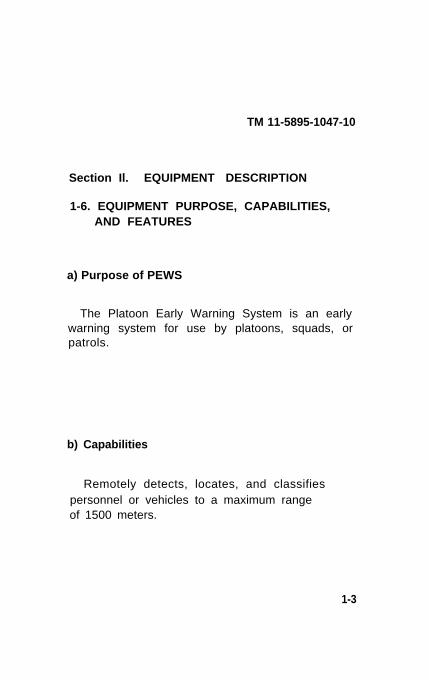
1-6. EQUIPMENT PURPOSE, CAPABILITIES,AND FEATURES
a) Purpose of PEWS
The Platoon Early Warning System is an earlywarning system for use by platoons, squads, orpatrols.
b) Capabilities
Remotely detects, locates, and classifiespersonnel or vehicles to a maximum rangeof 1500 meters.
1-3

TM 11-5895-1047-10
c) Features
● L i g h t w e i g h t
● Weatherproof
● Battery operated
• Easily concealed
● Built in self-test circuits
● Re l i ab l e
• Remotely operated
d) Components (Two bags each containing)
1- Receiver
1- Adapter, Receiver Antenna
1- Receiver Antenna
5- Detectors
5- Detector Antennas
1- Grounding Rod
1- Wire Link
1- Headset
10- Detector Holding Stakes
1-4
TM 11-5895-1047-10
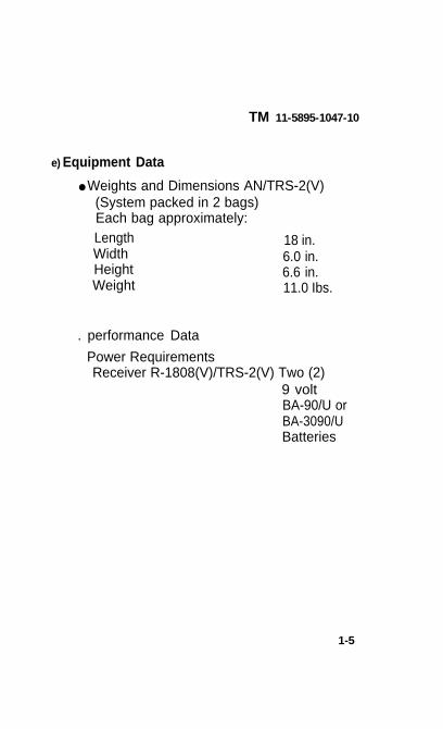
e) Equipment Data
● Weights and Dimensions AN/TRS-2(V)(System packed in 2 bags)Each bag approximately:Length 18 in.Width 6.0 in.Height 6.6 in.Weight 11.0 Ibs.
. performance Data
Power RequirementsReceiver R-1808(V)/TRS-2(V) Two (2)
9 voltBA-90/U orBA-3090/UBatteries
1-5
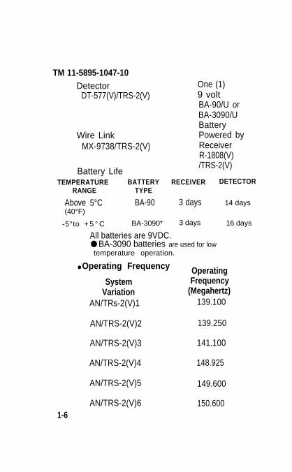
TM 11-5895-1047-10Detector One (1)
DT-577(V)/TRS-2(V) 9 voltBA-90/U orBA-3090/UBattery
Wire Link Powered byMX-9738/TRS-2(V) Receiver
R-1808(V)
Battery Life/TRS-2(V)
TEMPERATURE BATTERY RECEIVER DETECTORRANGE TYPE
Above 5°C BA-90 3 days 14 days(40°F)
-5°to + 5 ° C BA-3090* 3 days 16 days
All batteries are 9VDC.● BA-3090 batteries are used for lowtemperature operation.
● Operating Frequency OperatingSystem Frequency
Variation (Megahertz)AN/TRs-2(V)1 139.100
AN/TRS-2(V)2 139.250
AN/TRS-2(V)3 141.100
AN/TRS-2(V)4 148.925
AN/TRS-2(V)5 149.600
AN/TRS-2(V)6 150.6001-6

TM 11-5895-1047-10
1-7. DESCRIPTION OF MAJOR COMPONENTS
1
2
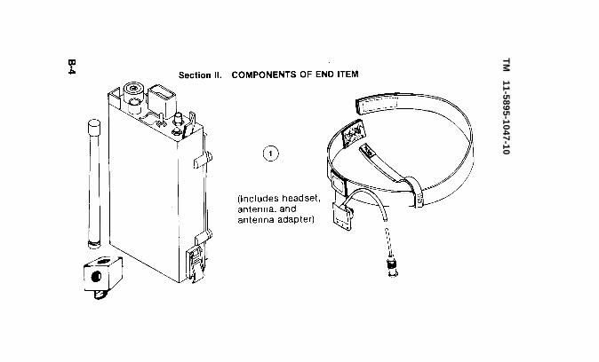
R E C E I V E R . ( 2 e a c h ) B a t t e r y - o p e r a t e dand weather proof. Receives radio signal orwire (using attached wire link) transmissionsfrom detectors. Sends audible alarm signal toheadset. Displays message in display window.Has self-test capability.
ANTENNA. (2 each) Screws into ANT socket onreceiver. Used when operating in RF mode. In-cludes adapter so that antenna may be proper-ly positioned.
1-7

TM 11-5895-1047-10
3
4
1-8
HEADSET ASSEMBLY. (2 each) Connects toPHONE connector on receiver. Sounds audiblealarm when detector reports intruder.
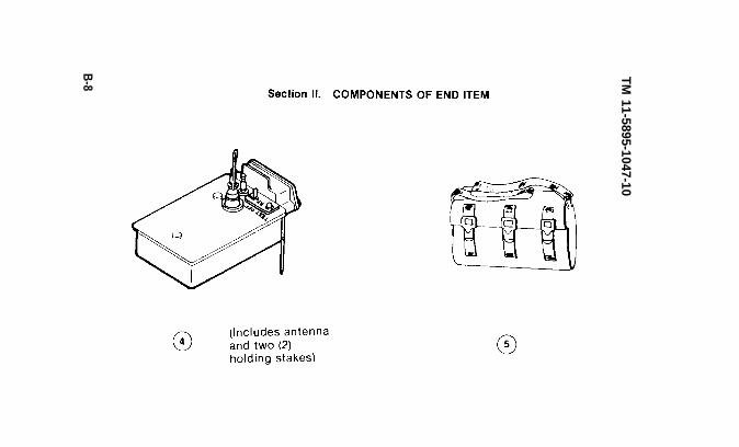
DETECTOR. (10 each) Small, light-weight, bat-tery powered. Detects ground vibrations (per-sonnel) or magnetic (vehicle) intrusions. Sendsmessage to receiver by RF or wire transmis-sion. Adapts to different environments, Hasself-test features. Detector antenna screws in-to top of unit. Two ground holding stakesscrew into bottom of each dSector.
TM 11-5895-1047-10
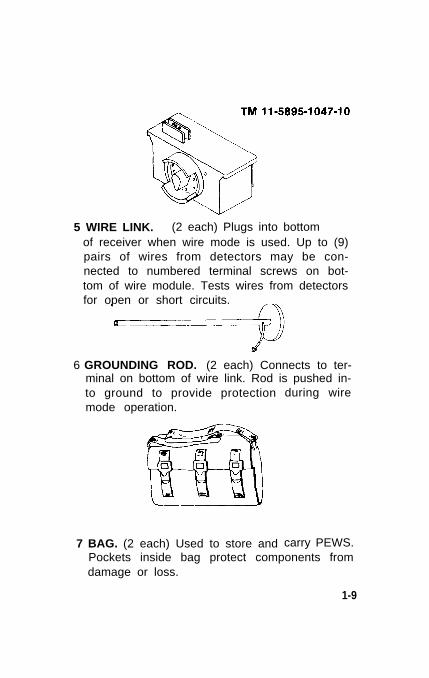
5 WIRE LINK. (2 each) Plugs into bottomof receiver when wire mode is used. Up to (9)pairs of wires from detectors may be con-nected to numbered terminal screws on bot-tom of wire module. Tests wires from detectorsfor open or short circuits.
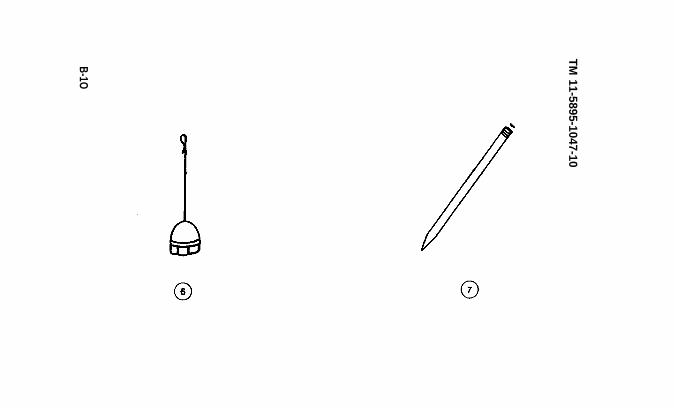
6 GROUNDING ROD. (2 each) Connects to ter-minal on bottom of wire link. Rod is pushed in-to ground to provide protectionmode operation.
7 BAG. (2 each) Used to store and
during wire
carry PEWS.Pockets inside bag protect components fromdamage or loss.
1-9
TM 11-5895-1047-10
1-8. DIFFERENCES IN EQUIPMENT.
The PEWS is available in six different operatingfrequencies. The var ia t ion number in thenomenclature is used to designate the operatingfrequency.
Detectors and receiver variation numbers must bethe same.
1-9. TECHNICAL PRINCIPLES OFOPERATION.
SYSTEMThe AN/TRS-2(V) has two modes of operation, an
RF mode and a wire mode. In the RF mode, detec-tor DT-577(V)/TRS-2(V) detects the presence of anintruder and determines the type of intrusion (per-sonnel or vehicle). The detector then transmits acoded signal to Receiver R-1808(V)/TRS-2(V). Thesignal is processed by the receiver which pro-duces an audible tone, digital display or both,identifying the detector that is sensing anintrusion.
In the wire mode the detector is connected tothe receiver via field wire using Wire Link MX-9738/TRS-2(V). The wire link provides for connec-tion of up to nine detectors to a single receiver.Received signals are processed in the same man-ner as described for the RF mode.
1-10

TM 11-5895-1047-10CHAPTER 2
OPERATING INSTRUCTIONS
Section I. DESCRIPTION AND USE OF
2-1.
OPERATOR’S CONTROLS ANDINDICATORS
RECEIVER R-1 808( V)/TRS-2(V) CONTROLSA N D I N D I C A T O R S
DISPLAY WINDOW shows ID number of detec-tor transmitting to receiver and type of in-truder. First two digits are ID numbers (1 to 16),last digit is “P” (personnel intruder) or “C”(vehicle intruder).
TEST RESET button allows you to test receiverbattery and display. When pressed and held in,normal display is 8.8.8. If battery is Jew, displayis 8 8 L or L. TEST RESET button also erasesalarm messages from receiver memory andclears display when pressed momentarily.
2-1
TM 11-5895-1047-10
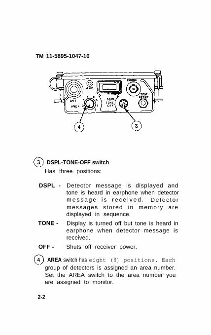
DSPL-TONE-OFF switch
Has three positions:
DSPL -
TONE -
OFF -
Detector message is displayed andtone is heard in earphone when detectorm e s s a g e i s r e c e i v e d . D e t e c t o rmessages s tored in memory aredisplayed in sequence.
Display is turned off but tone is heard inearphone when detector message isreceived.
Shuts off receiver power.
AREA switch has eight (8) positions. Eachgroup of detectors is assigned an area number.Set the AREA switch to the area number youare assigned to monitor.
2-2

TM 11-5895-1047-10
2-2. DETECTOR DT-577(V)/TRS-2(V)CONTROLS AND INDICATORS
oI ANTENNA post allows you to connectantenna to detector
o2 DATA terminal posts provide for connection ofwire pair to wire link.
o3 RF-OFF-W switch has three positions:
RF - selects the RF (radio) mode of operation
OFF -
w -
(wireless)
turns off detector power
selects the wire mode of operation (wiresmust be connected to terminal posts)
TEST button provides for check of transmittersection. 2-3
TM 11-5895-1047-I0
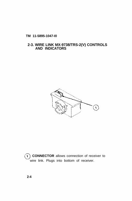
2-3. WIRE LINK MX-9738/TRS-2(V) CONTROLSAND INDICATORS
CONNECTOR allows connection of receiver towire link. Plugs into bottom of receiver.
2-4

TM 11-5895-1047-10
REC/TEST switch has ten positions:
REC position is used during operation.(Receive).
TEST positions 1-9 allow you to test field wireconnections for open or short circuits.
TEST IND lights when REC TEST switch isturned to a wire link pair number.
STEADY light indicates that field wire is notbroken or shorted.BLINKING light indicates that wire is broken orshorted.
WIRE TERMINALS 1 thru 9 are used toconnect field wire pairs from wire link to thedetectors. GND terminal is used to attach leadfrom ground rod to wire link.
2-5

TM 11-5895-1047-10Section Il. PREVENTIVE MAINTENANCE
CHECKS AND SERVICES
2-4. GENERAL.
To be sure that equipment is always readyfor your mission, you must do scheduledpreventive maintenance checks and ser-vices. (PMCS).
PMCS TABLE
There are three categories of PMCS: B, D, and A.They are at the top of the INTERVAL column of thePMCS table. A check mark in one or more of theINTERVAL columns indicates the check and/orservice that you should perform at a particulartime.
a. B means before. B-PMCS is performedBEFORE operation to make sure that thesystem is ready to work.
b. D means during. D-PMCS is performed DURINGoperation.
c. A means after. A-PMCS is performed AFTERoperation.
2-5. ROUTINE CHECKSRoutine checks consist of cleaning and dusting
checking for damaged equipment and missingparts. These are things you should do anytime yousee they are required. Routine checks are notlisted in the PMCS table.
2-6

TM 11-5895-1047-10
2-7

TM 11-5895-1047-10
NOTE
Use the ITEM NO. column in your PMCS table toget the numbers for the TM ITEM NO. column
on DA Form 2404 (Equipment Inspectionand Maintenance Worksheet) when you
fill out the form.
2-8

TM 11-5895-1047-10Section III. OPERATION UNDER USUAL
CONDITIONS2-6. ASSEMBLY AND PREPARATION FOR USE
Check contents of carrying case against Com-ponents of End Item List (COEIL) to make sure thePEWS is complete. Check identification plates ofreceivers and detectors to be sure variationnumbers are the same.
2-9

TM 11-5895-1047-10
a) Receiver Preparation (RF MODE)
(1) Battery Installation
Receiver R-1808(V)/TRS-2(V) requires two bat-teries for operation. Batteries are installed asfollows:
BATTERIES(BOTTOM)
LATCH BATTERY COMPARTMENT
●
●
●
●
2-10
REAR VIEW
Set DSPL-TONE-OFF Switch to OFF.
Release latches on receiver battery compart-ment.
Remove battery compartment cover to ex-pose battery connector.
Snap batteries into place and position inbattery compartment as shown.
Replace cover and secure latches.

TM 11-5895-1047-10
(2) Antenna/Headset Installation
Install receiver antenna and headset as follows:
●
●
Install receiver antenna adapter onto ANTsocket on front panel. Then connect anten-na to adapter.
Connect headset to PHONE jack.
2-11

TM 11-5895-1047-10b) Detector Preparation (RF MODE)
(1) Battery Installation
Detector DT-577(V)/TRS-2(V) requires one bat-tery for operation. Install battery as follows:
KNURLED SCREW
●
●
●
●
●
PAD BATTERY COVER
END VIEW
Set RF-OFF-W switch to OFF.
Loosen knurled screws to release batterycover.Snap battery into clip and place in compart-ment with connector against pad.Note area code and detector ID on inside ofbattery compartment cover. List on receiverwriting surface.
Close battery compartment and tightenknurled screws.
2-12
TM 11-5895-1047-10
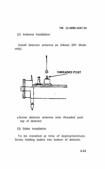
(2) Antenna Installation
Install detector antenna as follows (RF Modeonly):
● Screw detector antenna onto threaded posttop of detector.
(3) Stake Installation
To be installed at time of deployment/use.Screw holding stakes into bottom of detector.
2-13

TM 11-5895-1047-10c) Receiver Preparation (WIRE MODE)
(1) Battery Installation
Receiver R-1808)/TRS-2 requires two batteriesfor operation. Batteries are installed as follows:
COVER REMOVED
BATTERY COMPARTMENT WIRE LINKCONNECTOR
REAR VIEW
●
●
●
●
Set DSPL-TONE-OFF Switch to OFF.
Release latches on receiver battery compart-ment.
Remove battery compartment cover to ex-pose battery connector.
Snap batteries into place and position inbattery compartment as shown.
2-14

TM 11-5895-1047-10
(2) Wire Link Installation.
Connect wire link to receiver base as shownbelow.
Push on and latch.
2-15
TM 11-5895-1047-10
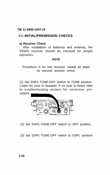
2-7. INITIAL/PREMISSION CHECKS
a) Receiver CheckAfter installation of batteries and antenna, the
PEWS receiver should be checked for properoperation.
NOTE
Procedure is for one receiver, repeat all stepsfor second receiver check.
(1) Set DSPL-TONE-OFF Switch to TONE position.Listen for tone in headset. If no tone is heard referto troubleshooting section for corrective pro-cedure.
(2) Set DSPL-TONE-OFF switch to OFF position.
(3) Set DSPL-TONE-OFF switch to DSPL position.
2-16

TM 11-5895-1047-10
NOTE
If an “L” remains batteries areshould be replaced.
low and
2-17

TM 11-5895-1047-10
(4) Press and hold TEST-RESET button andobserve for this display.
b) Detector Check
NOTEThe following steps require a working
receiver.
(1) Set the receiver to DSPL.
(2) Set the receiver AREA switch to the samearea number as the detector under test.
2-18

TM 11-5895-1047-10
(3) Check all detectors for RF Mode of operationas follows:
NOTE
Procedure is for one detector. Repeat allsteps for each detector.
(a) Test the detector for operation by placingpower switch to RF and press and releaseTEST button. Observe receiver displayresponse.
for
2-19

TM 11-5895-1047-10
Receiver display must indicate:
(b) If detector does not operate correctly; referto troubleshooting section for correctiveprocedure.
2-20

TM 11-5895-1047-10
c) Wire Link Check.
NOTE
Procedure is for one wire link. Repeat allsteps for the 2nd wire.
(1) Connect wire link to an operating receiver.
(2) Set TEST switch through positions 1 thru 9and observe flashing indicator.
2-21
TM 11-5895-1047-10
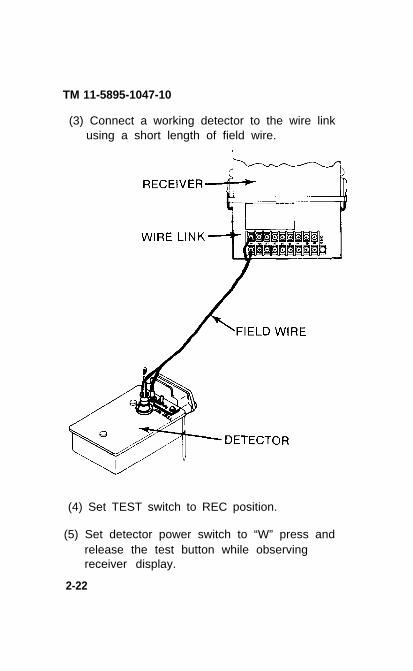
(3) Connect a working detector to the wire linkusing a short length of field wire.
(4) Set TEST switch to REC position.
(5) Set detector power switch to “W” press andrelease the test button while observingreceiver display.
2-22

TM 11-5895-1047-10
Receiver display must indicate:
(6) Remove field wire from detector and wire link.
(7) Remove wire link and replace cover onreceiver.
2-23

TM 11-5895-1047-10
d) Receiver Memory Check.
Connect two (2) working detectors to theReceiver by RF Mode or Wire mode or acombination of both.
(1) Set DSPL-TONE-OFF switch to DSPL andpress and release TEST button on both detec-tors (not at the same time).
(2) Observe display for approximately 30seconds. During this time the detectornumbers from the 2 test detectors should ap-pear alternately in the display.
(3) Press TEST/RESET button on receiver whileobserving display. Display should blank out.
2-24

TM 11-5895-1047-10
2-8. SYSTEM PLANNING AND INSTALLATIONa) Installation Planning
(1) System Planning
The PEWS will be installed in accordance withparticular security requirements of a site.
Site Considerations:
Size of area to be protected (How manydetectors you will need).
Type of terrain.
Type of soil in area.
Noise level in area.
Tactical considerations (whether there arepaths or roads to be monitored, location ofcamp site etc.).
2-25

TM 11-5895-1047-10
1 DETECTOR POSITION
2 RECEIVER POSITION
TYPICAL PEWS CAPABILITY
2-26
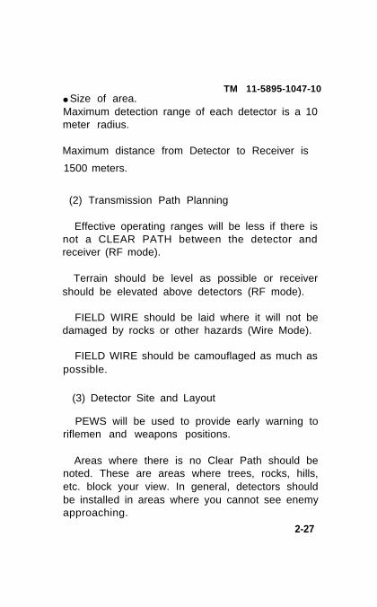
TM 11-5895-1047-10● Size of area.Maximum detection range of each detector is a 10meter radius.
Maximum distance from Detector to Receiver is
1500 meters.
(2) Transmission Path Planning
Effective operating ranges will be less if there isnot a CLEAR PATH between the detector andreceiver (RF mode).
Terrain should be level as possible or receivershould be elevated above detectors (RF mode).
FIELD WIRE should be laid where it will not bedamaged by rocks or other hazards (Wire Mode).
FIELD WIRE should be camouflaged as much aspossible.
(3) Detector Site and Layout
PEWS will be used to provide early warning toriflemen and weapons positions.
Areas where there is no Clear Path should benoted. These are areas where trees, rocks, hills,etc. block your view. In general, detectors shouldbe installed in areas where you cannot see enemyapproaching.
2-27

TM 11-5895-1047-10b) Installation of Detectors
After choosing detector sites, install as-sembled detectors.
• Dig shallow hole at detector location aboutone inch deep, slightly larger than detector.
Ž Sketch out the location and ID numbers ofeach detector you install to be sure that youhave fully covered area to be protected. Youmay sketch on the writing area located on thereceiver.
NOTE
When emplacing detector, observearrow and note on detector case.
When detecting vehicles, the detectormust be aligned so that arrow
is parallel to expectedtravel of vehicles.
Ž Push detector into hole so that holdingstakes are firmly implanted into ground. DO
NOT STEP ON DETECTOR.2-28

TM 11-5895-1047-10
• Pack soil firmly against sides of detectorcase. Do not cover top of detector case.
• If detector is to be used in wire mode, strip in-sulation from ends of field wire with wire cut-ters.
• Insert each wire end into terminal posts ondetector by pressing down top of post in-serting wire into post
Ž Run field wire to receiver location;camouflage as necessary.
2-29

TM 11-5895-1047-10NOTE
Detector antennas are NOT required for wiremode of operation. Do NOT allow any plants or
other objects to touch detector antenna or datapost.
●
●
●
Turn detector on - set RF-OFF-W switch to RF(for radio mode) or W (for wire mode).
Camouflage detector as necessary.
Repeat the above steps for installation ofother detectors.
2-30
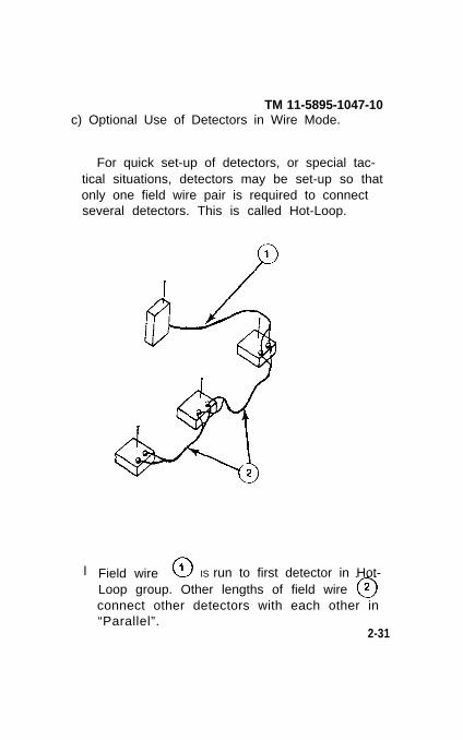
TM 11-5895-1047-10c) Optional Use of Detectors in Wire Mode.
For quick set-up of detectors, or special tac-tical situations, detectors may be set-up so thatonly one field wire pair is required to connectseveral detectors. This is called Hot-Loop.
l Field wire IS run to first detector in Hot-Loop group. Other lengths of field wire connect other detectors with each other in“Parallel”.
2-31

TM 11-5895-1047-10
●
●
●
●
●
Attach wire link to receiver.
S t r i p ends o f f i e l d w i r e pa i r s f r omdetectors.
Using screwdriver, connect one pair of wiresfrom each detector to numbered terminal onwire link (installed on receiver).
Using screwdriver, connect wire lead fromground rod to GND terminal on wire link.
Push ground rod into soil in area wherereceiver is to remain operating.
CAUTION
Grounding rod should always be connectedto the wire link during operation to prevent elec-
trical shock.
2-32

TM 11-5895-1047-10
• To operate PEWS, set DPSL-TONE-OFF switchto either the DPSL or TONE position.
• When intruder is detected the display win-dow will indicate alarm in the DPSLposition. In addition a tone will be heardin the headset.
Ž For tone operation only, set the switch tothe TONE position. When an intruder isdetected tone will be heard in headset
NOTE
Use TONE position to conserve battery duringlong periods of monitoring.
If battery is low, an “L” will be displayeddisplay window even if TONE position isselected.
in
2-33

TM 11-5895-1047-10
ŽWhen in wire mode be sureREC-TEST switch on wire link
is set to REC position.
ŽSet AREA switch to detector area (assigned toeach detector) you want to monitor.
Check your sketch on writing surfaceof receiver to determine proper AREA
number of detector.
Detecting an intruder (DSPL position).
1. When receiver is first turned on,an 8. 8. 8. will appear in display windowand tone will sound for about ten seconds.
2-34

TM 11-5895-1047-10
2. Display should then clear.You can check receiver for proper display or low
battery at any time during operation by using TESTRESET but ton. Press but ton in and ho ld ;
should always appear in display w i n d o w .
3. When detector senses intruder, message issent to receiver.
Detector ID number appears on receiver display.
Intruder classification displays (P = personnel,C = vehicle).
Decimal points will always light when a new in-trusion is displayed.
Tone will sound in headset.
4. Information is stored in receiver memory.
When new messages from other detectors arereceived, they will be momentarily displayed onreceiver with decimal points and tone.
When no new messages are being received,previously received (old) messages (withoutdecimal points) are repeated in display window inrotation (starting with lowest number).
2-35

TM 11-5895-1047-10
If both personnel and vehicle intrusions aredetected, they will both be displayed and repeatedin rotation, starting with the lowest detector IDnumber.
Turning DSPL-TONE-OFF switch to TONE willmake display go blank, but will not erase receivermemory.
To erase memory, press TEST RESET button on receiver.
5. If you see the same ID numbers (withdecimals and audio alert) displayed morethan once, there may be more than one in-truder near detector.
2-36

TM 11-5895-1047-10Detecting an intruder (TONE position).
Operation in TONE position is the same as inDSPL position, except that no display will ap-pear in WINDOW.
If tone is heard in headset while monitoring forintruder, turn DSPL-TONE-OFF switch toDSPL position.
ID number and classification of intruder will ap-pear on display.
Any messages stored in receiver memory will bedisplayed in rotation.
Switching from DSPL to TONE or TONE to DSPLwill not erase receiver memory.
NOTE
When detectors are reporting at a high rate(many intruders), there is a greater chance
of false alarm messages.2-37

TM 11-5895-1047-10
Detector identification.
After you have noted the ID number(s) ofdetector(s) that is reporting, refer to your deploy-ment sketch to find area and location of detec-tor.
Using your deployment sketch, it may bepossible to determine movements of a largenumber of intruders by noting which detectorsare reporting.
2-38

System shut down.TM 11-5895-1047-10
Set receiver DSPL-TONE-OFF switch to OFFposition.
If the tactical situation permits, turn DetectorRF-OFF-W switches to the OFF position.
2-39

TM 11-5895-1047-10
2-10. PREPARATION FOR MOVEMENT
When leaving a site, disassemble system asfollows:
NOTE
Retrieve detectors only if authorized to do so.
Pickup detectors from their positions.
Turn RF-OFF-W switch to OFF position.
Disconnect field wire from terminals (if inwire mode).
Unscrew antennas from top of detectors (ifin RF mode).
Unscrew holding stakes from bottom ofdetectors.
Wipe any dirt from components with cloth.Store components in bag.
2-40

TM 11-5895-1047-10
b. Wire Link
Disconnect field wire pairs from terminalswith screwdriver.
Disconnect ground rod lead from wire linkand store in center pocket of bag.
Unlatch wire link from receiver and store inbag.
Replace battery compartment cover onreceiver.
2-41

TM 11-5895-1047-10
Unscrew antenna from adapter and store inbag.
Disconnect headset from connector armstore in bag.
Place receiver in bag.
Make sure all components of the PEWS are ac-counted for. Refer to the Components of End ItemList (appx B) and check system for completeness.2-42
TM 11-5895-1047-10
Section IV. OPERATION UNDER UNUSUALCONDITIONS
2-11. OPERATION IN UNUSUAL WEATHER
The AN/TRS-2(V) is fully sealed and weather pro-tected for operation in hot, cold, damp or moderateclimates. However under extreme conditions, thefollowing conditions may exist:
a. Extreme Cold Climate. Extreme cold causesfield wire to become hard, brittle, and difficult tohandle. Binding posts and connectors are subjectto damage from hard ground and icing conditions.
b. Hot Climates. In hot dry climates, connectorsand binding posts are subject to damage fromdust and sand.
c. Warm Damp Climates. In warm damp climates,the equipment is subject to damage from moistureand fungi.
d. Cold Dampthe equipmentmoisture.
Climates. In coldis subject to
damp climatesdamage from
2-43

TM 11-5895-1047-10
2-12. PRECAUTlONS TC FOLLOW
For cold weather operation use BatteryBA-3090 in lieu of BA-90.
Make sure that binding posts, connectors,headset and antennas are free of ice, snow,dust, or sand.
Be sure the receiver and detector batterycovers are in place.
Never drag or place loose end of headsetcable in the snow drift, sand or hard ground.
Be sure to remove dirt, moisture, and fungifrom equipment.
2-44
TM 11-5895-1047-10CHAPTER 3. MAINTENANCE INSTRUCTIONS
3-1. LUBRICATION INSTRUCTIONS
The PEWS does not require lubrication.
3-2. TROUBLESHOOTING PROCEDURES
Troubleshoot the PEWS using theseprocedures as your guide.
a.
b.
These are the common malfunctions whichyou may find during the operation ormaintenance of the PEWS or its components.You should perform the tests/inspectionsand corrective actions in the order listed.
This manual cannot list all malfunctions thatmay occur, nor all tests or inspections andcorrective actions. If a malfunction is notlisted or is not corrected by listed correctiveactions, notify your supervisor.
TROUBLESHOOTING GUIDE
MALFUNCTIONTEST OR INSPECTIONCORRECTIVE ACTION
RECEIVER
1. NO DISPLAY OR TONE OBTAINEDOPERATION
DURING
3-1

TM 11-5895-1047-10TROUBLESHOOTING RECEIVER
(Continued)
Step 1. Check to see that batteries are good.
Replace batteries and re-check operation,
Step 2. Check that DSPL-TONE-OFF switch isin DSPL or TONE position.
Set switch to DSPL or TONE position
Step 3. Check that AREA switch is in the
correct position.
Set AREA switch to correct position. If abovesteps fail, replace receiver.
2. NO DISPLAY OBTAINED DURING OPERATION(TONE HEARD)
Step 1. Check to see that batteries are good.
Replace batteries and re-check operation.
3. NO TONE HEARD IN HEADSET (DISPLAY O. K.)
Step 1. Check to see that headset plug is pro-perly connected to receiver.
Tighten headset connector.
3-2

TM 11-5895-1047-10
TROUBLESHOOTING RECEIVER(Continued)
Step 2. Check that headset is operative. Plugheadset to other receiver. Turn DSPL-TONE-OFFswitch to DSPL position and press TEST RESETbutton. Tone should be heard.
If no tone is heard, replace headset.
4. “L” APPEARS ON RECEIVER DISPLAY
Step 1. Check condition of batteries.
Replace batteries and re-check operation.
5. NO RF OPERATION
Step 1. Check that antenna is connected pro-perly. Insure that connector or antenna adapter isnot corroded or dirty.
Replace antenna or adapter if necessary.
Step 2. Check that radio paths are not heirblocked by hills, metallic objects, or other sourof interference.
Move receiver to minimize blockage.
3 -3

TM 11-5895-1047-10TROUBLESHOOTING RECEIVER
(Continued)
6. NO WIRE LINK OPERATION
Step 1. Check that wire link is securely install-ed on receiver.
Disconnect and reinstall wire link.
Step 2. Check that field wires are connectedproperly to terminals on wire link and are notshorted or broken.
Replace or splice wire.
If any of the above steps fail to correct receivermalfunction, replace receiver.
3-4

TM 11-5895-1047-10
TROUBLESHOOTING DETECTOR
1. DETECTOR INOPERATIVE (WIRE AND RFMODE)
Step 1. Check that RF-OFF-W switch is set toRF or W position.
Set switch to RF or W Position.
Step 2. Check to see that detector batteries aregood.
Re-check operation using TEST button.
Step 3. Check that detector code plug is install-ed firmly in its socket.
Push code plug into socket gently.
3-5
TM 11-5895-1047-10
TROUBLESHOOTING DETECTOR(Continued)
Step 4. If using detector in wire mode, insurethat field wires connected to detector are secure(not broken or shorted).
Fix connections as necessary.
If above steps fail to correct detector malfunc-tion, replace detector.
Step 5. If using detector in RF mode, insure thatantenna is connected to post and antenna is nottouching any external objects.
Tighten antenna and/or clear external objects.
WIRE LINK1. WIRE LINK INOPERABLE (NOOPERATION IN WIRE MODE, RECEIVER BAT-TERIES O. K.)
Step 1. Check that wire link is securelyfastened to receiver.
Secure wire link properly.
Step 2. Insure that REC-TEST switch is set toREC position.
Set switch to REC position,
If above steps fail to correct wire linkmalfunctions, replace wire link.
3-6

TM 11-5895-1047-10
3-3. CLEANING
a.
b.
c.
d
Receiver . Receiver should be c leanedwhenever necessary using clean, dry, lint-freecloth. You may use small amounts of water ifnecessary.
Detectors and holding stakes. Detectors andholding stakes should be cleaned with clothafter operation. Wipe any dirt from surfacesbefore placing components back in bag.
Wire l ink. Clean wire l ink with cloth asnecessary. Insure that no terminal screws aremissing.
Ground rod. Clean ground rod with cloth asnecessary. Be certain that wire lead and ter-minal are not damaged.
3-7

TM 11-5895-1047-10
APPENDIX AREFERENCES
The following is a list of applicable referencesthat are available to the operator of the Pews.
AR 385-40 Accident Reporting andRecords
DA Pam 310-4 Index of TechnicalManuals, TechnicalBulletins, Supply Manuals(Types 7, 8, and 9), Fabrica-tion Orders
DA Pam 310-7 U.S. Army Equipment Indexof Modification WorkOrders
TM 38-750 The Army MaintenanceManagement System(TAMMS)
A-1

TM 11-5895-1047-10APPENDIX B
COMPONENTS OF END ITEM AND BASICISSUE lTEMS LISTS
Section L INTRODUCTION
1. Scope
This appendix lists integral components of andbasic issue items for the PEWS to help you inven-tory items required for safe and efficient opera-tion.
2. General
The Components of End Item and Basic IssueItems Lists are divided into the following sections:
a. Section Il. Components of the End Item. Thislisting is for informational purposes only, and isnot authority to requisition replacements. Theseitems are part of the end item, but are removed andseparately packaged for transportation or ship-ment. As part of the end item, these iterns must bewith the end item whenever it is issued or transfer-red between property accounts. Illustrations arefurnished to assist you in identifying the items.
b. Section Ill. Basic Issue Items. These are theminimum essential items required to place thePEWS in operation, to operate it, and to performemergency repairs. Although shipped separatelypackaged Bll must be with the PEWS during opera-tion and whenever it is transferred between pro-perty accounts. The illustrations will assist youwith hard-to-identify items. This manual is yourauthority to request/requisition replacement Bll,based on TOE/MTOE authorization of the end item.
B-1
TM 11-5895-1047-10
B-3. Explanation of Columns
The following provides an explanation of columnsfound in the tabular listings:
a. Column (1) - Illustration Number (Illus Number).This column indicates the number of the illustra-tion in which the item is shown.
b. Column (2) - National Stock Number. Indicatesthe National stock number assigned to the itemand will be used for requisitioning purposes.
c. Column (3) - Description. Indicates the Na-tional item name and, if required, a minimumdescription to identify and locate the item. Thelast line for each item indicates the FSCM (inparentheses) followed by the part number. If itemneeded differs for different models of this equip-ment, the model is shown under the ‘r Usable On”heading in this column. These codes are identifiedas:
Code Used On
DTJ AN/TRS-2(v)1DZ3 AN/TRS-2(v)2DZ4 AN/TRS-2(V)3DZ5 AN/TRS-2(V)4DZ6 AN/TRS-2(V)5DZ7 AN/TRS-2(V)6
B-2

TM 11-5895-1047-10
3. Explanation of Columns (Cont.)
d. Column (4) - Unit of Measure (U/M). (4) In-dicates the measure used in performing the actualoperational/maintenance function. This measureis expressed by a two-character alphabetical ab-breviation (e.g., ea., in., pr.).
e. Column (5) - Quantity required (Qty rqr).(5) Indicates the quantity of the item authorized tobe used with/on the equipment.
B-3
B-4
Section II.
TM
11-5895-1047-10

TM
11-5895-1047-10
B-5

Section II.
TM 11-5895-1047-10
B-6

TM
11-5895-1047-10
B-7
Section II.
TM 11-5895-1047-10
B-8

B-9
TM 11-5895-1047-10
TM 11-5895-1047-10
B-1O

Section III.
TM 11-5895-1047-10
B-11/B
-12 b
lank

TM 11-5895-1047-10
APPENDIX CADDITIONAL AUTHORIZATION LIST
Section I. INTRODUCTION
1. Scope
This appendix lists additional items you areauthorized for the support of the PEWS.
2. General
This list identifies items that do not have to ac-company the PEWS and that do not have to beturned in with it. These items are all authorized toyou by CTA, MTOE, TDA, or JTA.
3. Explanation of Listing
National stock numbers, descriptions, andquantities are provided to help you identify and re-quest the additional items you require to supportth is equ ipment . T h e i t e m s a r e l i s t e d i nalphabetical sequence by item name under typedocument (i.e., MTOE) which authorizes the itemto you.
C-1

C-2
Section II.
TM
11-5895-1047-10

TM 11-5895-1047-10
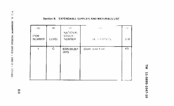
APPENDIX DEXPENDABLE SUPPLIES & MATERIALS LIST
Section I. INTRODUCTION
1. Scope
This appendix lists expendable supplies andmaterials you will need to operate and maintainthe PEWS. These items are authorized to you byCTA 50-970, Expendable Items (Except Medical,Class V, Repair Parts, and Heraldic Items).
2. Explanation of Columns
a. Column (1) - Item number. This number isassigned to the entry in the listing and is referenc-ed in the narrative instructions to identify the.material (e.g., “Use cleaning compound, item 5,App. D”).
b. Column (2) - Level. This column identifies thelowest level of maintenance that requires thelisted item.
C - Operator/Crew
c. Column (3) - National Stock Number. This is theNational stock number assigned to the item, use itto request or requisition the item.
D-1

TM 11-5895-1047-10
2. Explanation of Columns (Cont.)
d. Column (4) - Description. Indicates the Federalitem name and, if required, a description to iden-tify the item. The last line for each item indicatesFederal Supply Code for Manufacturer (FSCM) inparentheses, followed by the part number.
e. Column (5) - Unit of Measure (U/M). Indicatesthe measure used in performing the actualmaintenance function. This measure is expressedby a two-character alphabetical abbreviation (e.g.,ea., in., pr.). If the unit of measure differs from theunit of issue, requisition the lowest unit of issuethat will satisfy your requirements.
D-2
Section II.
TM
1
1-5
89
5-1
04
7-1
0
D-3

TM 11-5895-1047-10
O! ST RI BUT ION:
Active Amy
& HISA (Ft Monmouth)UsA:N$+m (2)
COE (1)TSG (1)USAARENBD (1)DARCO?t ( 1 )TRADOC (2)0s *J Cd (4)TECOM (2)USACC (4)NOW (1)Armies (2)Corps (2)Svc College. (1)USASICS (5)USAADS (2)USAFAS (2)usMRm (2)USAIS (2)
NC: None
USAR: None
(21) USAES (2)USAICS (3)MAc (1)USANMS (1)USAE8DAA ( 1 )USAERDAW ( 1 )Ft Gordon (10)Ft Carson (5)Army Dep (1) except
SAAD (30)TOAD (14)SHAD (2)
Ft Gfllem (10)USA DeP (i)Sig Sec USA Dep (1)Ft Richardson (CERCOH Oft) (2>Units org under fol TOE:
29-207 (2)29-610 (2)
For explanation of abbreviation wed , see AR 31o-so.


PIN: 046585-002

This fine document...
Was brought to you by me:
Liberated Manuals -- free army and government manuals
Why do I do it? I am tired of sleazy CD-ROM sellers, who take publicly available information, slap “watermarks” and other junk on it, and sell it. Those masters of search engine manipulation make sure that their sites that sell free information, come up first in search engines. They did not create it... They did not even scan it... Why should they get your money? Why are not letting you give those free manuals to your friends?
I am setting this document FREE. This document was made by the US Government and is NOT protected by Copyright. Feel free to share, republish, sell and so on.
I am not asking you for donations, fees or handouts. If you can, please provide a link to liberatedmanuals.com, so that free manuals come up first in search engines:
<A HREF=http://www.liberatedmanuals.com/>Free Military and Government Manuals</A>
– SincerelyIgor Chudovhttp://igor.chudov.com/
– Chicago Machinery Movers