TM 11-5826-211-50 · TM 11-5826-211-50 DEPARTMENT OF THE ARMY TECHNICAL MANUAL ... Setting Synchro...
21
TM 11-5826-211-50 DEPARTMENT OF THE ARMY TECHNICAL MANUAL DEPOT MAINTENANCE MANUAL RADIO MAGNETIC INDICATOR ID-250A/ARN HEADQUARTERS, DEPARTMENT OF THE ARMY DECEMBER 1959
Transcript of TM 11-5826-211-50 · TM 11-5826-211-50 DEPARTMENT OF THE ARMY TECHNICAL MANUAL ... Setting Synchro...
TM 11-5826-211-50D E P A R T M E N T O F T H E A R M Y T E C H N I C A L M A N U A L
D E P O T M A I N T E N A N C E M A N U A L
R A D I O
M A G N E T I C I N D I C A T O R
I D - 2 5 0 A / A R N
H E A D Q U A R T E R S , D E P A R T M E N T O F T H E A R M Y
D E C E M B E R 1 9 5 9

HEADQUARTERS,DEPARTMENT OF THE ARMY
WASHINGTON 25, D.C., 10 December 1959
TM 11-5826-211-50 (a reprint of an Air Force TO 12R5-2ARN-213, 1 October 1956) ispublished for the use of Army personnel.
By Order of Wilber M. Brucker, Secretary of the Army:
L. L. LEMNITZER,General, United States Army,
Official: Chief of Staff.
R. V. LEE,Major General, United States Army,
The Adjutant General.
Distribution :
Active Army:
USASA (2)Def Atomic Spt Agcy (5)CNGB (1)Tech Stf, DA (1)
except CSigO (10)Tech Stf Bd (1)USA Arty Bd (1)USA Armor Bd (1)USA Inf Bd (1)USA AD Bd (1)USA Abn & Elct Bd ( 1 )USA Avn Bd (1)USA ATB (1)USCONARC (5)US ARADCOM (2)US ARADCOM Rgn (2)Log Cored (5)MDW (1)Armies 1 ) except
First US Army (3)USATC (2)
NG: None.USAR: None.For explanations of abbreviations used, see AR 320-50.
USASCS (25)Gen Dep (2) except
Atlanta Gen Dep ( None)Sig See, Gen Dep (10)Sig Dep (17)USA Ord Msl Comd (3)USASSA (15)USASSAMRO (1)USA Sig Pub Agcy (8)USA Sig Engr Agcy (1)USA Cornm Agcy (3)USA Sig Eqp Spt Agcy (2)USA Sig Msl Spt Agcy (2)Fld Cored. Def Atomic Spt Agcy (2)USA Elct PG (1)Sig Lab (5)USA Corps (Res) (1)
Units org under fol TOE:
11-587 (2) 11-597 (2)11-592 (2)
Section
I
II
III
T.O. 5N8-7-2-13
INTRODUCTION . . . . . . . .
1-1. Identification . . . . . .
1-2. Purpose of Equipment
1-3. Leading Particular. .
OVERHAUL INSTRUCTIONS
2-1.
2-5.
2-15.
2-17.
2-18.
2-20.
2-21.
2-23.
Special Tools . . . . . .
Disassembly . . . . . .
Cleaning . . . . . . . . .
Inspection . . . . . . . .
Testing . . . . . . . . . .
Table of Contents
. . . . . . . . . . . . . . . . . . . . . . . . . . .
. . . . . . . . . . . . . . . . . . . . . . . . . . .
. . . . . . . . . . . . . . . . . . . . . . . . . . .
. . . . . . . . . . . . . . . . . . . . . . . . . . .
. . . . . . . . . . . . . . . . . . . . . . . . . . .
. . . . . . . . . . . . . . . . . . . . . . . . . . .
. . . . . . . . . . . . . . . . . . . . . . . . . . .
. . . . . . . . . . . . . . . . . . . . . . . . . . .
. . . . . . . . . . . . . . . . . . . . . . . . . . .
. . . . . . . . . . . . . . . . . . . . . . . . . . .
Repair or Replacement. . . . . . . . . . . . . . . . . . . . . . . . . . .
Lubrication .
Reassembly .
TEST PROCEDURE
3-1.
3-3.
3-4.
3-6.
3-7.
3-10,
General . . . .
. . . . . . . . . . . . . . . . . . . . . . . . . . . . . . . . .
. . . . . . . . . . . . . . . . . . . . . . . . . . . . . . . . .
. . . . . . . . . . . . . . . . . . . . . . . . . . . . . . . . .
. . . . . . . . . . . . . . . . . . . . . .. . . . . . . . . . . . . .
Testing Ball Bearings . . . . . . . . . . . . . . . . . . . . . . . . . . .
Testing Synchros . . . . . . . . . . . . . . . . . . . . . . . . . . . . . .
Setting Synchro Electrical Zero..... . . . . . . . . . . . . . . . .
Testing Assembled Indicator . . . . . . . . . . . . . . . . . . . . . . .
Evacuating and Charging Indicator.. . . . . . . . . . . . . . . . . .
Page
1
1
1
1
1
1
2
7
8
8
8
8
8
13
13
13
13
13
15
15
i
ii
Section I T.O. 5N8-7-2-13
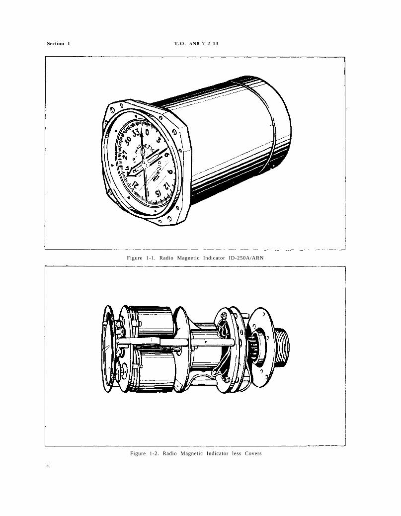
Figure 1-1. Radio Magnetic Indicator ID-250A/ARN
Figure 1-2. Radio Magnetic Indicator less Covers
SECTION I
T.O. 5N8-7-2-13 Sections I-II
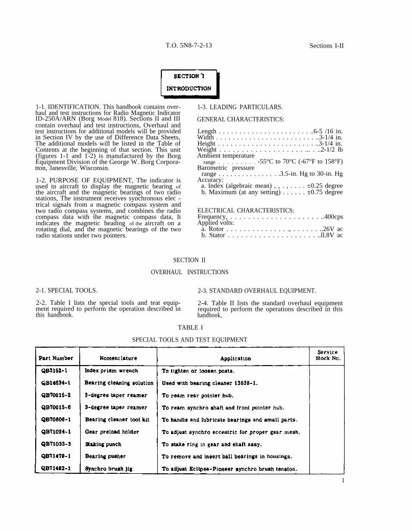
1-1. IDENTIFICATION. This handbook contains over- 1-3. LEADING PARTICULARS.haul and test instructions for Radio Magnetic IndicatorID-250A/ARN (Borg Model 818). Sections II and III GENERAL CHARACTERISTICS:contain overhaul and test instructions, Overhaul andtest instructions for additional models will be provided Length . . . . . . . . . . . . . . . . . . . . . . ..6-5 /16 in.in Section IV by the use of Difference Data Sheets, Width . . . . . . . . . . . . . . . . . . . . . . . . ..3-1/4 in.The additional models will be listed in the Table of Height . . . . . . . . . . . . . . . . . . . . . . . ..3-1/4 in.Contents at the beginning of that section. This unit Weight . . . . . . . . . . . . . . . . . . . ... . ..2-1/2 lb(figures 1-1 and 1-2) is manufactured by the Borg Ambient temperatureEquipment Division of the George W. Borg Corpora- range . . . . . . . . . -55°C to 70°C (-67°F to 158°F)tton, Janesville, Wisconsin. Barometric pressure
range . . . . . . . . . . . . . . . .3.5-in. Hg to 30-in. Hg1-2. PURPOSE OF EQUIPMENT, The indicator is Accuracy:used in aircraft to display the magnetic bearing of a. Index (algebraic mean) , , . , . . . . ±0.25 degreethe aircraft and the magnetic bearings of two radio b. Maximum (at any setting) . . . . . . ±0.75 degreestations, The instrument receives synchronous elec -trical signals from a magnetic compass system andtwo radio compass systems, and combines the radio ELECTRICAL CHARACTERISTICS:compass data with the magnetic compass data, It Frequency, . . . . . . . . . . . . . . . . . . . . ..400cpsindicates the magnetic heading of the aircraft on a Applied volts:rotating dial, and the magnetic bearings of the two a. Rotor . . . . . . . . . . . . . . ., . . . . . . ..26V acradio stations under two pointers. b. Stator . . . . . . . . . . . . . . . . . . . . ..ll.8V ac
SECTION II
OVERHAUL INSTRUCTIONS
2-1. SPECIAL TOOLS. 2-3. STANDARD OVERHAUL EQUIPMENT.
2-2. Table I lists the special tools and teat equip- 2-4. Table II lists the standard overhaul equipmentment required to perform the operation described in required to perform the operations described in thisthis handbook. handbook,
TABLE I
SPECIAL TOOLS AND TEST EQUIPMENT
1
Section IIParagraphs 2-5 to 2-7
T.O. 5N8-7-2-13
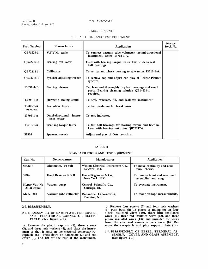
TABLE I (CONT)
SPECIAL TOOLS AND TEST EQUIPMENT
Part Number
QB71520-1
QB72217-2
QB72218-1
QB74218-I
13638-1-B
13693-1-A
13700-1-Aor equal
13703-1-A
13716-1-A
58534
Cat. No.
Model 1
31OA
Hyper Vat. No25 or equal
Model 300
Nomenclature
V.T.V.M. cable
Bearing test rotor
Calibrator
Synchro adjusting wrench
Bearing cleaner
Hermetic sealing stand
Insulation tester
Omni-directional instru-ment tester
Bear ing torque tester
Spanner wrench
Application
To connect vacuum tube voltmeter toomni-directionalinstrument tester 13703-1-A.
Used with bearing torque teater 13716-1-A to testball bearings.
To set up and check bearing torque tester 13716-1-A.
To remove cap and adjust end play of Eclipse-Pioneersynchro.
To clean and thoroughly dry ball bearings and smallparts. Bearing cleaning solution QB14634-1required.
To seal, evacuate, fill, and leak-test instrument.
To test insulation for breakdown.
To test indicator.
To test ball bearings for starting torque and friction.Used with bearing test rotor QB72217-2.
Adjust end play of Oster synchro.
ServiceStock No.
TABLE II
STANDARD TOOLS AND TEST EQUIPMENT
Nomenclature
Ohmmeter, 10-volt
Hand Remover K& D
Vacuum pump
Vacuum tube voltmeter
Manufacturer
Weston Electrical Instrument Co.,Newark, NJ.
Hamel Rigiander & Co.,New York, N.Y.
Central Scientific Co.,Chicago, Ill.
Ballantine Laboratories,Boonton, N.J.
Application
To make continuity and resis-tance checks.
To remove front and rear handassemblies and ring.
To evacuate instrument.
To make voltage measurements,
2-5. DISASSEMBLY. b. Remove four screws (7) and four iock washers
2-6. DISASSEMBLY OF NAMEPLATE, END COVER,AND ELECTRICAL CONNECTOR RECEP-TACLE. (See figure 2-1.)
a. Remove the plastic cap nut (1), three screws(3), and three lock washers (4), and place the instru-ment so that it rests on the electrical connector re-ceptacle (6). Press down on nameplate (2) and endcover (5), and lift off the rest of the instrument.
(8). Push back the 13 pieces of tubing (9) on fourblack insulated wires (10), three blue insulatedwires (11), three red insulated wires (12), and threeyellow insuiated wires (13); and unsolder the wiresfrom the electrical connector receptacle (6). Re-move the receptacle and plug support plate (14).
2-7. DISASSEMBLY OF BEZEL, TERMINAL AS-SEMBLY, COVER AND GLASS ASSEMBLY.(See figure 2-1.)
2
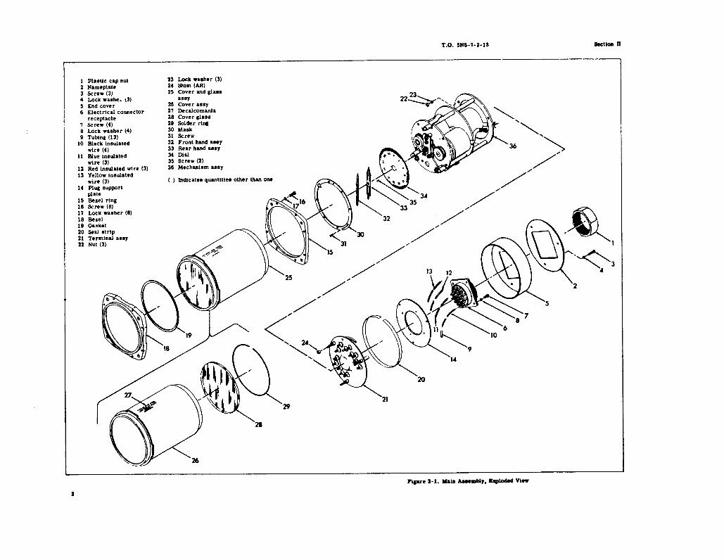
Figure 2-1.
T.O
. 5N8-7-2-13
Section II
3
4
Section II T.O. 5N8-7-2-13
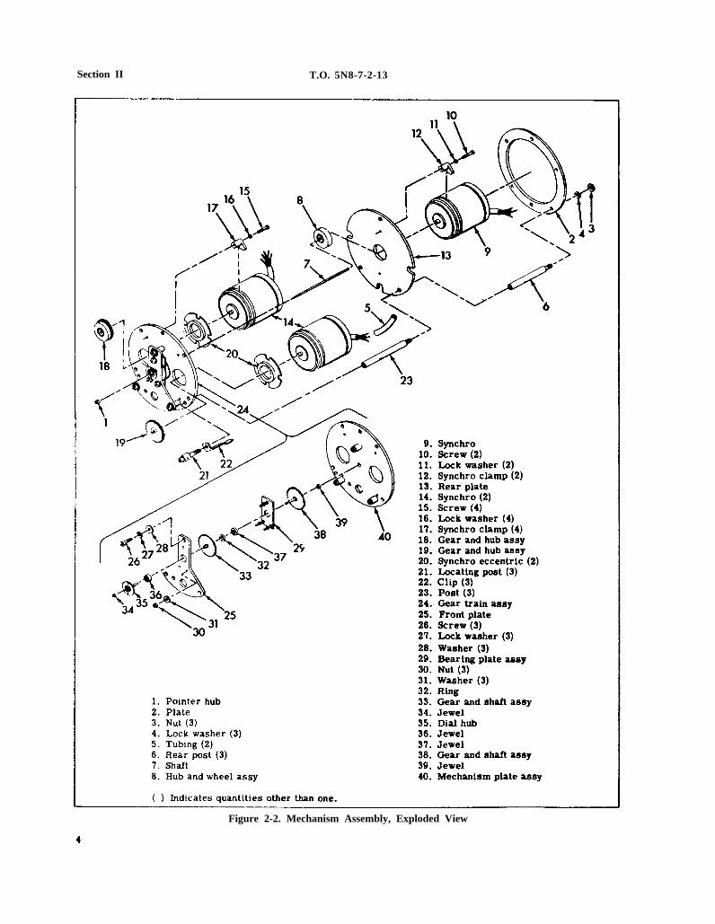
Figure 2-2. Mechanism Assembly, Exploded View
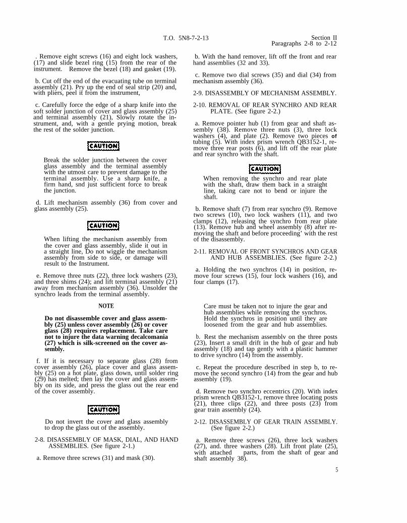
. Remove eight screws (16) and eight lock washers,(17) and slide bezel ring (15) from the rear of theinstrument. Remove the bezel (18) and gasket (19).
b. Cut off the end of the evacuating tube on terminalassembly (21). Pry up the end of seal strip (20) and,with pliers, peel it from the instrument,
c. Carefully force the edge of a sharp knife into thesoft solder junction of cover and glass assembly (25)and terminal assembly (21), Slowly rotate the in-strument, and, with a gentle prying motion, breakthe rest of the solder junction.
Break the solder junction between the coverglass assembly and the terminal assemblywith the utmost care to prevent damage to theterminal assembly. Use a sharp knife, afirm hand, snd just sufficient force to breakthe junction.
d. Lift mechanism assembly (36) from cover andglass assembly (25).
T.O. 5N8-7-2-13 Section II
When lifting the mechanism assembly fromthe cover and glass assembly, slide it out ina straight line, Do not wiggle the mechanismassembly from side to side, or damage willresult to the Instrument.
e. Remove three nuts (22), three lock washers (23),and three shims (24); and lift terminal assembly (21)away from mechanism assembly (36). Unsolder thesynchro leads from the terminal assembly.
NOTE
Do not disassemble cover and glass assem-bly (25) unless cover assembly (26) or coverglass (28) requires replacement. Take carenot to injure the data warning decalcomania(27) which is silk-screened on the cover as-sembly.
f. If it is necessary to separate glass (28) fromcover assembly (26), place cover and glass assem-bly (25) on a hot plate, glass down, until solder ring(29) has melted; then lay the cover and glass assem-bly on its side, and press the glass out the rear endof the cover assembly.
Do not invert the cover and glass assemblyto drop the glass out of the assembly.
2-8. DISASSEMBLY OF MASK, DIAL, AND HANDASSEMBLIES. (See figure 2-1.)
a. Remove three screws (31) and mask (30).
Paragraphs 2-8 to 2-12
b. With the hand remover, lift off the front and rearhand assemblies (32 and 33).
c. Remove two dial screws (35) and dial (34) frommechanism assembly (36).
2-9. DISASSEMBLY OF MECHANISM ASSEMBLY.
2-10. REMOVAL OF REAR SYNCHRO AND REARPLATE. (See figure 2-2.)
a. Remove pointer hub (1) from gear and shaft as-sembly (38). Remove three nuts (3), three lockwashers (4), and plate (2). Remove two pieces oftubing (5). With index prism wrench QB3152-1, re-move three rear posts (6), and lift off the rear plateand rear synchro with the shaft.
When removing the synchro and rear platewith the shaft, draw them back in a straightline, taking care not to bend or injure theshaft.
b. Remove shaft (7) from rear synchro (9). Removetwo screws (10), two lock washers (11), and twoclamps (12), releasing the synchro from rear plate(13). Remove hub and wheel assembly (8) after re-moving the shaft and before proceeding’ with the restof the disassembly.
2-11. REMOVAL OF FRONT SYNCHROS AND GEARAND HUB ASSEMBLIES. (See figure 2-2.)
a. Holding the two synchros (14) in position, re-move four screws (15), four lock washers (16), andfour clamps (17).
b.
Care must be taken not to injure the gear andhub assemblies while removing the synchros.Hold the synchros in position until they areloosened from the gear and hub assemblies.
Rest the mechanism assemblv on the three posts(23), Insert a small drift in the hub of gear and hubassembly (18) and tap gently with a plastic hammerto drive synchro (14) from the assembly.
c. Repeat the procedure described in step b, to re-move the second synchro (14) from the gear and hubassembly (19).
d. Remove two synchro eccentrics (20). With indexprism wrench QB3152-1, remove three locating posts(21), three clips (22), and three posts (23) fromgear train assembly (24).
2-12. DISASSEMBLY OF GEAR TRAIN ASSEMBLY.(See figure 2-2.)
a. Remove three screws (26), three lock washers(27), and. three washers (28). Lift front plate (25),with attached parts, from the shaft of gear andshaft assembly 38).
5
6
Section IIParagraphs 2-13 to 2-14
When lifting the front plate, take care tolift it straight up to avoid damaging theshaft of the gear and shaft assembly.
b. Remove three nuts (30) and three washers (31)which secure bearing plate assembly (29). Do notremove the three posts unless they must be re-placed.
c. Using a block of wood with a hole drilled to re-ceive dial hub (35), rest front plate (25) on itsfront face. With the hand remover, lift off ring(32). Remove gear and shaft assembly (33). Se-parate the front plate and dial hub. Remove gearand shaft assembly (38) from mechanism plate as-sembly (40).
T.O. 5N8-7-2-13
synchro adjusting wrench QB74218-1, remove cap(2).
d. Do not press jewel (34) from dial hub (35),jewel (36) from front plate (25), jewel (37) frombearing plate assembly (29), or jewel (39) frommechanism plate assembly (40) unless they re-quire replacement.
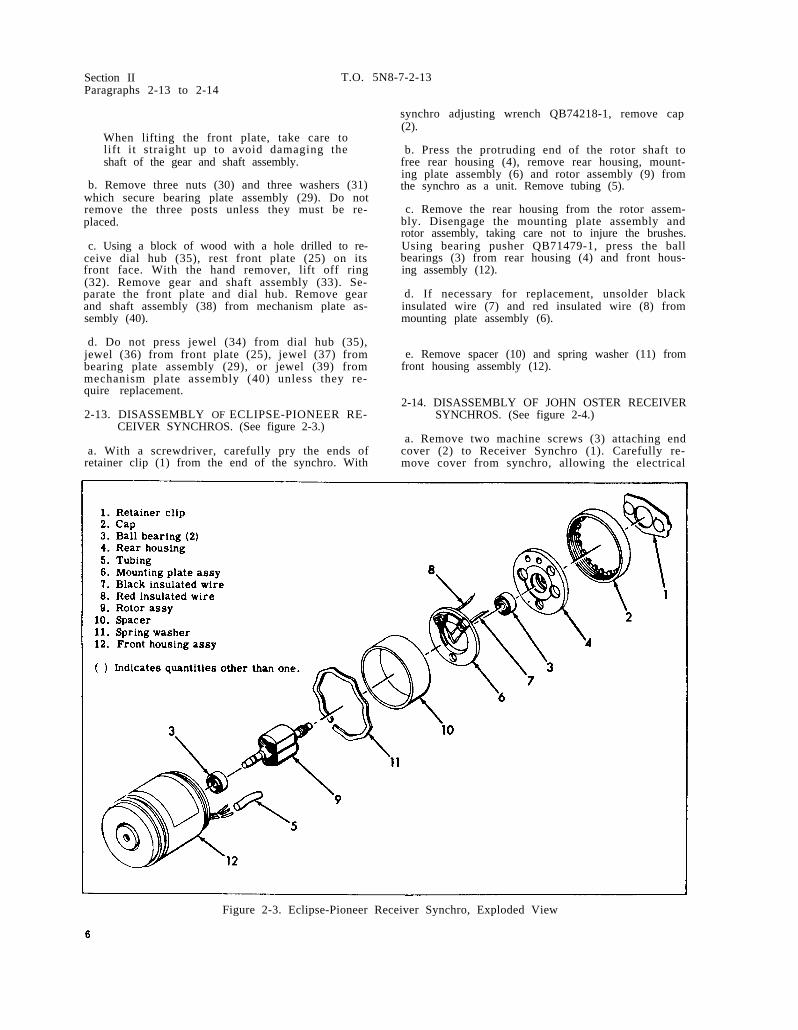
2-13. DISASSEMBLY OF ECLIPSE-PIONEER RE-CEIVER SYNCHROS. (See figure 2-3.)
a. With a screwdriver, carefully pry the ends ofretainer clip (1) from the end of the synchro. With
b. Press the protruding end of the rotor shaft tofree rear housing (4), remove rear housing, mount-ing plate assembly (6) and rotor assembly (9) fromthe synchro as a unit. Remove tubing (5).
c. Remove the rear housing from the rotor assem-bly. Disengage the mounting plate assembly androtor assembly, taking care not to injure the brushes.Using bearing pusher QB71479-1, press the ballbearings (3) from rear housing (4) and front hous-ing assembly (12).
d. If necessary for replacement, unsolder blackinsulated wire (7) and red insulated wire (8) frommounting plate assembly (6).
e. Remove spacer (10) and spring washer (11) fromfront housing assembly (12).
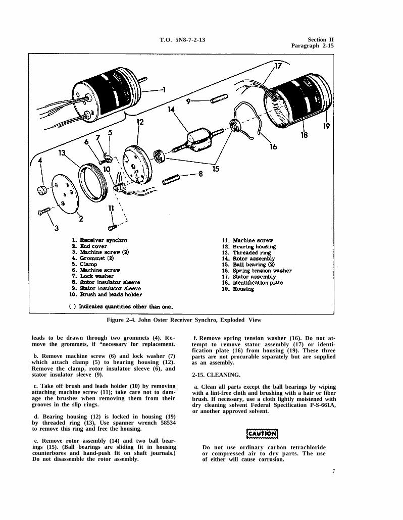
2-14. DISASSEMBLY OF JOHN OSTER RECEIVERSYNCHROS. (See figure 2-4.)
a. Remove two machine screws (3) attaching endcover (2) to Receiver Synchro (1). Carefully re-move cover from synchro, allowing the electrical
Figure 2-3. Eclipse-Pioneer Receiver Synchro, Exploded View
T.O. 5N8-7-2-13 Section IIParagraph 2-15
Figure 2-4. John Oster Receiver Synchro, Exploded View
leads to be drawn through two grommets (4). Re-move the grommets, if “necessary for replacement.
b. Remove machine screw (6) and lock washer (7)which attach clamp (5) to bearing housing (12).Remove the clamp, rotor insulator sleeve (6), andstator insulator sleeve (9).
c. Take off brush and leads holder (10) by removingattaching machine screw (11); take care not to dam-age the brushes when removing them from theirgrooves in the slip rings.
d. Bearing housing (12) is locked in housing (19)by threaded ring (13), Use spanner wrench 58534to remove this ring and free the housing.
e. Remove rotor assembly (14) and two ball bear-ings (15). (Ball bearings are sliding fit in housingcounterbores and hand-push fit on shaft journals.)Do not disassemble the rotor assembly.
f. Remove spring tension washer (16). Do not at-tempt to remove stator assembly (17) or identi-fication plate (16) from housing (19). These threeparts are not procurable separately but are suppliedas an assembly.
2-15. CLEANING.
a. Clean all parts except the ball bearings by wipingwith a lint-free cloth and brushing with a hair or fiberbrush. If necessary, use a cloth lightly moistened withdry cleaning solvent Federal Specification P-S-661A,or another approved solvent.
Do not use ordinary carbon tetrachlorideor compressed air to dry parts. The useof either will cause corrosion.
7
Section II T.O. 5N8-7-2-13Paragraphs 2-16 to 2-24
b. Carefully remove all solder from the cover andglass assembly and the terminal assembly to in-sure even seating of parts when the instrument isreassembled.
c. Cover all parts after cleaning to keep them dustfree.
2-16. CLEANING BALL BEARINGS. Clean and lub-ricate ball bearings as follows:
a. Use bearing cleaning tool kit QB70606-1, bear-ing cleaner 13638-1, and bearing cleaning solutionQB14634-1, or dry cleaning solvent Federal Speci-fication P-S-661A for handling, washing, and lub-ricating ball bearings.
b. Select or assemble a mandrel from the bearingcleaning tool kit, Put the bearing on the mandrelwith tweezers, and place the retainer over the bearing.
Always use tweezers to handle bearings.Fingering bearings will cause corrosion.
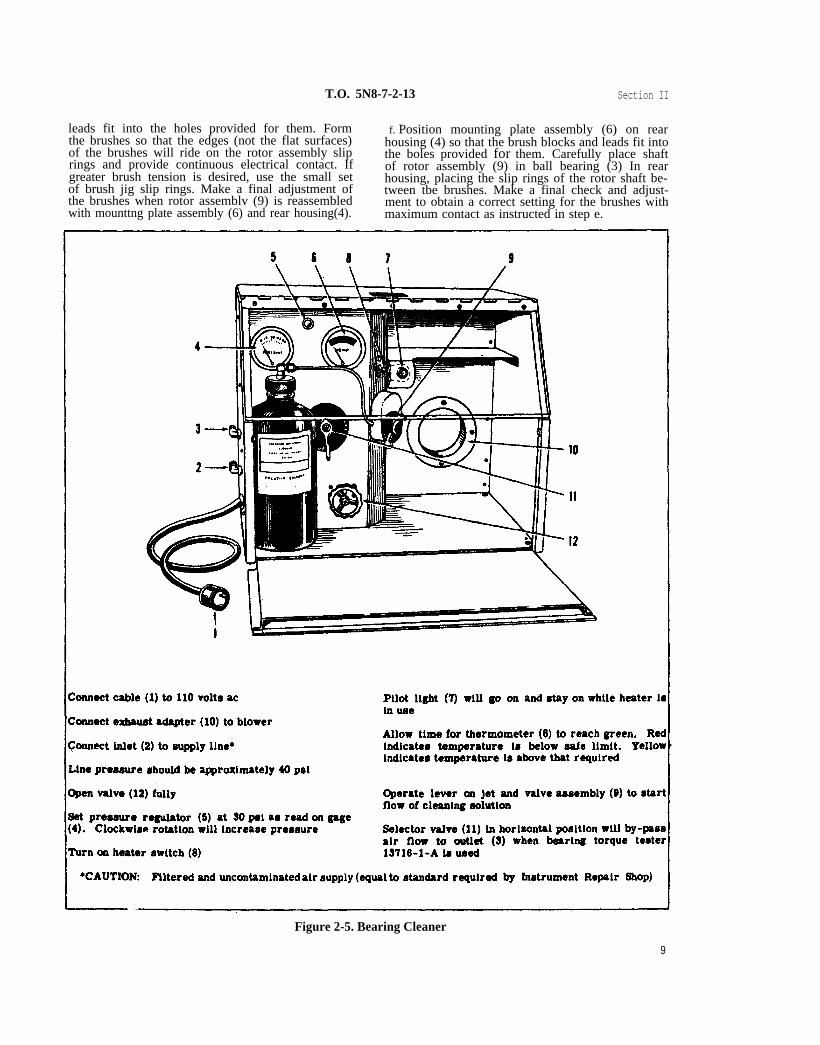
c. Connect and adjust bearing cleaner 13638-1 (fig-ure 2-5). Hold the bearing 3/16-inch from the jet andallow the jet to clean the bearing thoroughly. Turnone of the bearing races slowly to dislodge dirt orchips from around the bearing balls and their sep-arator,
Do not allow the bearing to spin on the man-drel. The lapping caused by the dirty sol-vent will ruin the bearing.
d. Turn off the jet, and set the selector valve (11,figure 2-5) in the horizontal position. Dry the bear-ing completely in the air flow at outlet (3). Immedi -ately after drying, lubricate per paragraph 2-21.
2-17. INSPECTION.
a. Examine all parts of the indicator for cracks,chipping, corrosion, and excessive wear. Examineall threaded components for stripped and worn threadsor other damage. Repair or replace damaged andworn parts prior to reassembly.
b. Inspect the slip rings and brushes for discolora-tion. Remove even the slightest discoloration bypolishing with fine crocus cloth and wiping clean withthe glossy side of soft tissue paper. If excessive wearor pitting is found, replace the part.
2-18. TESTING.
2-19. Test the rotor and stator resistances with theohmmeter, If rotor resistance does not lie between14.4 and 17.6 ohms, or stator resistance does not liebetween 5.5 and 6.7 ohms, replace the defective part.
2-20. REPAIR OR REPLACEMENT.
a. Check the ground surfaces of the synchro rotor andstator for corrosion. If anti-corrosive treatment has
8
not been applied to these parts, or if the anti-corrosivecoating is scratched, apply a new lacquer coating.Wipe off all defective coating with lacquer thinner(Roxalin Thinner No, 75), and polish laminated faceswith No. 0000 emery cloth until surfaces are smoothand clean. Do not touch surfaces with fingers. Afterpolishing, clean the rotor and stator assemblieswith blasts of clean, dry air. Wipe the surfaces tobe treated with a cloth dampened in lacquer thinneruntil all grit and foreign matter have been removed.Allow the rotor and stator to dry thoroughly.
b. Mask all surfaces not to be treated with maskingtape, and heat the parts to approximately 16.6°C(30° F) above ambient temperature. While the Partsare warm, spray the laminated surfaces with a thincoat (0.0002 -inch maximum thickness) of PaladinBlack Finish No. 12412, mixed with enough RoxalinThinner No. 75 to prevent cobwebbing of sprayedsurfaces.
c. Bake finish for one hour at 121°C (250° F), re-move parts from oven, and allow to cool at roomtemperature. If oven is not available, air dry. Donot reassemble parts until thoroughly dry and do notscratch coating.
2-21. LUBRICATION.
2-22. Immediately after drying, lubricate bearingswith two drops of lubricating oil, Specification MIL -L-6085, using a syringe. Do not allow the syringeto touch the bearing. Make certain that all surfacesof the bearings are coated with oil. Test ball bear-ings as outlined in paragraph 3-3.
It is imperative that the bearing be lubricatedimmediately after cleaning. Inspect bearingfor flaws, corrosion, or other damage; thenlubricate. After oiling bearing, place in aclean, dust -proof container until ready for use,
2-23. REASSEMBLY.
2-24. REASSEMBLY OF ECLIPSE - PIONEER RE-CEIVER SYNCHROS. (See figure 2-3.)
a. Slip tubing (5) over the stator leads of the fronthousing assembly (12).
b. With bearing pusher QB71479-1, install the twoball bearings (3) in the front housing assembly (12)and the rear housing (4). Select ball bearings for ahandpush fit in housings and a sliding fit on the shaftof rotor assembly (9).
c. Place spring washer (11) and spacer (10) in fronthousing assembly (12), keeping the stator leads clear,
d. If the black and red insulated wires (7 and 8) havebeen removed, solder them to their respective placeson mounting plate assembly (6).
e. Place mounting plate assembly (6) in synchrobrush jig QB71482-1, so that the brush blocks and
T.O. 5N8-7-2-13 Section II
leads fit into the holes provided for them. Form f. Position mounting plate assembly (6) on rearthe brushes so that the edges (not the flat surfaces) housing (4) so that the brush blocks and leads fit intoof the brushes will ride on the rotor assembly slip the boles provided for them. Carefully place shaftrings and provide continuous electrical contact. If of rotor assembly (9) in ball bearing (3) In reargreater brush tension is desired, use the small set housing, placing the slip rings of the rotor shaft be-of brush jig slip rings. Make a final adjustment of tween tbe brushes. Make a final check and adjust-the brushes when rotor assemblv (9) is reassembled ment to obtain a correct setting for the brushes withwith mounttng plate assembly (6) and rear housing(4). maximum contact as instructed in step e.
Figure 2-5. Bearing Cleaner
9
Section II T.O. 5N8-7-2-13Paragraphs 2-25 to 2-27
g. Carefully slip shaft of rotor assembly (9) Infront housing ball bearing(3). Gently bring housingstogether with key in rear housing (4) fitting into theslot in the front housing assembly (12).
h. Slip cap (2) over the stator and brush leads.With synchro adjusting wrench QB74218-1, screw thecap on front housing assembly (12) until the rotorshaft has 0.0015-inch end play with a one-ounce loadand 0.004-inch end play with a one-pound load. Twonotches in the cap must be in line with each hole inrear housing (4), Snap retainer clip (1)’ into place.
2-25. REASSEMBLY OF JOHN OSTER RECEIVERSYNCHROS, (See figure 2-4.)
a. Reassembly of the John Oster Receiver Synchrois essentially the reverse of disassembly. Refer tothe instructions prescribed in paragraph 2-14 and tothe index sequence of figure 2-4 to reassemble thissynchro.
b. Threaded ring (13) must be tightened down (usingspanner wrench (58534) in housing (19) until the shaftof rotor assembly (14) has 0.0015-inch end play witha one-ounce load and 0.004-inch end play with a one-pound load.
c. Particular care must be taken that the brusheson brush and leads holder (10) have correct alignmentand tension in the clip ring grooves of rotor assem-bly (14).
2-26. REASSEMBLY OF GEAR TRAIN ASSEMBLY.(See figure 2-2.)
a. If necessary, replace the three posts in the mech-anism plate assembly and the three posts in thebearing plate assembly. Spin the peats over againstthe rear of the plate tightly.
b. Press jewel (39) into mechanism plate assembly(40) until it is flush with the plate front face.
c. Assemble bearing plate assembly (29) to frontplate (25) with three nuts (30) end three washers (31),but do not tighten the nuts. Assemble the frontplate to the mechanism plate assembly with threescrews (26), three lock washers (27), and threewashers (28), but do not tighten the screws.
d. Press jewel (37) into bearing plate assembly (29)until it is flush with the aide opposite the mountingstuds.
e. Press jewel (36) into front plate (25) until itslarger diameter is 0.003 to 0.005 inch above the sur-face plate,
f. Press jewel (34) as far into dial hub (35) as itwill go.
g. Place dial hub (35) through jewel (36) in frontplate (25), inserting a 0.010-inch shim (slotted toreceive the dial hub shaft) between the bearing sur-faces of the dial hub and jewel. Place gear and shaftassembly (33) on the shaft of the dial hub, and slip
10
ring (32) over the split hub of the gear and shaftassembly. Press the ring tightly on the split hub,and stake it lightly with staking punch QB71033-3.Remove the shim from between the dial hub and thejewel.
h. Secure front plate (25) and bearing plate assem-bly (29) by tightening three lock washers (31) andthree nuts (30), Check that dial hub (35) does notrest against the jewel in the front plate in any way.Check the end play of the dial hub. It should be0.004 (±0.002) inch. If the dial hub rests against thejewel in the front plate, adjust the setting of the jew-els in the front plate and the bearing plate. If theend play of the dial hub is out of tolerance, readjustjewels mentioned in the previous sentence. Place therear shaft of gear and shaft assembly (38) in jewel(39) which was previously installed in mechanismplate assembly (40), Lower the front plate andattached parts over the front shaft of gear and shaftassembly (38) so that the shaft passes through thehub of gear and shaft assembly (33) and protrudesslightly from the front of dial hub (35).
When assembling gear and shaft assembly(38), be careful not to bend or damage shaft.
i. Secure front plate (25) to mechanism plate assem-bly (40) by tightening three screws (26), three lockwashers (27), and three washers (28).
j. Check the end play of the two gear and shaftassemblies (33 and 38). In each case, the end playshould be 0.005 (±0.002) inch. If the end play doesnot fall within these limits, readjust the setting ofthe jewel in mechanism plate assembly (40).
2-27. REASSEMBLY OF MECHANISM PLATE AS-SEMBLY. (See figure 2-2.)
a. With index prism wrench QB3152-1, replacethree posts (23), three clips (22), and three locatingposts (21) on gear train assembly (24).
b. Place two synchro eccentrics (20) in mechanismplate assembly (40), with their high sides at the cen-ter, Attach two synchros (14) with four clamps (17).four screws (15), and four lock washers (16), but donot tighten the screws. Place two pieces of tubing(5) on the synchro leads.
c. Place shaft (7) in a pin vise; set the rear synchro(9) face up on the bench, and guide the shaft into thebushing in the synchro shaft. With a light plastichammer, tap the top of the pin vise lightly to drivethe shaft into the bushing, Remove the pin vise.
Be careful not to drive the shaft too deeplyinto the synchro bushing. Tapping too hardwill injure the bushing and the shaft.
d. After inserting shaft (7) in rear synchro (9) asinstructed in step c, place the synchro in position on
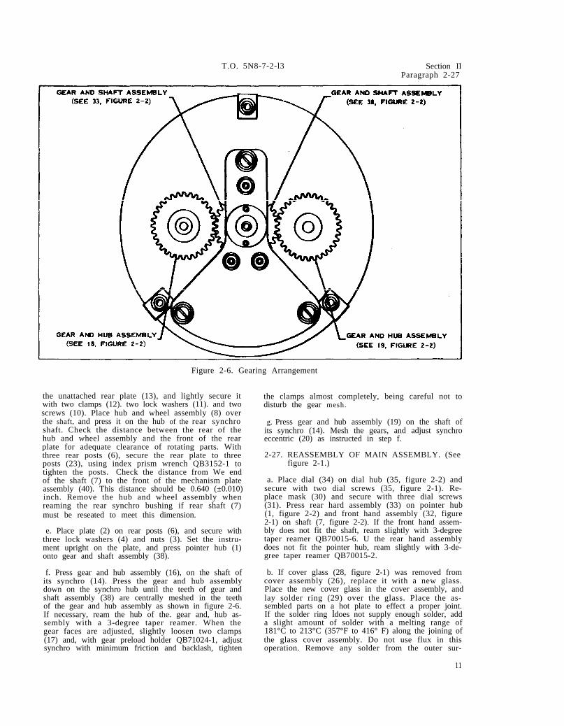
FIGURE 2-2 FIGURE 2-2
FIGURE 2-2 FIGURE 2-2
T.O. 5N8-7-2-l3 Section IIParagraph 2-27
Figure 2-6. Gearing Arrangement
the unattached rear plate (13), and lightly secure itwith two clamps (12). two lock washers (11). and twoscrews (10). Place hub and wheel assembly (8) overthe shaft, and press it on the hub of the rear synchroshaft. Check the distance between the rear of thehub and wheel assembly and the front of the rearplate for adequate clearance of rotating parts. Withthree rear posts (6), secure the rear plate to threeposts (23), using index prism wrench QB3152-1 totighten the posts. Check the distance from We endof the shaft (7) to the front of the mechanism plateassembly (40). This distance should be 0.640 (±0.010)inch. Remove the hub and wheel assembly whenreaming the rear synchro bushing if rear shaft (7)must be reseated to meet this dimension.
e. Place plate (2) on rear posts (6), and secure withthree lock washers (4) and nuts (3). Set the instru-ment upright on the plate, and press pointer hub (1)onto gear and shaft assembly (38).
f. Press gear and hub assembly (16), on the shaft ofits synchro (14). Press the gear and hub assemblydown on the synchro hub until the teeth of gear andshaft assembly (38) are centrally meshed in the teethof the gear and hub assembly as shown in figure 2-6.If necessary, ream the hub of the. gear and, hub as-sembly with a 3-degree taper reamer. When thegear faces are adjusted, slightly loosen two clamps(17) and, with gear preload holder QB71024-1, adjustsynchro with minimum friction and backlash, tighten
the clamps almost completely, being careful not todisturb the gear mesh.
g. Press gear and hub assembly (19) on the shaft ofits synchro (14). Mesh the gears, and adjust synchroeccentric (20) as instructed in step f.
2-27. REASSEMBLY OF MAIN ASSEMBLY. (Seefigure 2-1.)
a. Place dial (34) on dial hub (35, figure 2-2) andsecure with two dial screws (35, figure 2-1). Re-place mask (30) and secure with three dial screws(31). Press rear hard assembly (33) on pointer hub(1, figure 2-2) and front hand assembly (32, figure2-1) on shaft (7, figure 2-2). If the front hand assem-bly does not fit the shaft, ream slightly with 3-degreetaper reamer QB70015-6. U the rear hand assemblydoes not fit the pointer hub, ream slightly with 3-de-gree taper reamer QB70015-2.
b. If cover glass (28, figure 2-1) was removed fromcover assembly (26), replace it with a new glass.Place the new cover glass in the cover assembly, andlay solder ring (29) over the glass. Place the as-sembled parts on a hot plate to effect a proper joint.If the solder ring ldoes not supply enough solder, adda slight amount of solder with a melting range of181°C to 213°C (357°F to 416° F) along the joining ofthe glass cover assembly. Do not use flux in thisoperation. Remove any solder from the outer sur-
11
Section II T.O. 5N8-7-2-13
face of cover and glass assembly (25). When thecover glass has assumed Its proper position due tosolder flow, push the assembled parts to an adjoiningsurface on the same level as the hot plate, and allowthe parts to cool undisturbed. Place the cover andglass assembly face down on the scraping fixture ofhermetic sealing stand 13693-1-A, and rotate it toscrape off excess solder from the front of the coverand glass assembly. Teat the cover and glass as-sembly for leaks, using the clamp fixture in the her-metic sealing stand. Place the clamp around thecover and glass assembly so that the rear opening ofthe cover assembly is sealed off. Connect the out-put on the clamp to the Hyper Vac. No. 25 vacuumpump. Fill the cover and glass assembly to 15psi, and check for leaks by immersing it in water.Dry the assembly completely after testing for leaks.
c. Check mechanism assembly (36) in cover andglass assembly (25) for proper distance of the handsfrom the cover glass. Place a fiber spacer 1/32-inch thick and of slightly smaller diameter than thecover glass in the cover and glass assembly, Pushthe mechanism assembly into the cover and glassassembly in a straight line so that front hand assem-bly (32) rests against the fiber spacer. Select shims(24) so that when they are placed on terminal assem-bly (21), the terminal assembly will rest tightlyagainst the rear end of the glass assembly. Theshims are 0.015-inch and 0.047-inch thick, respec -tively. When the correct shims have been selected,remove the terminal and mechanism assembles,and fiber spacer from the cover and glass assembly.
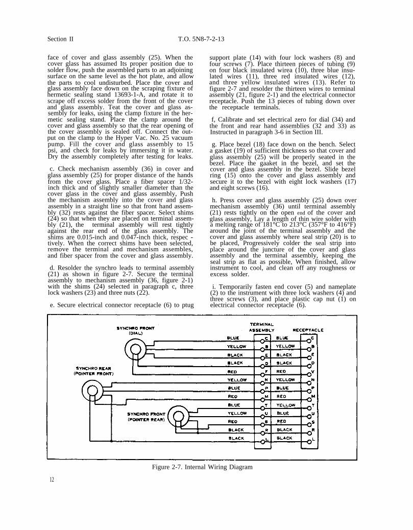
d. Resolder the synchro leads to terminal assembly(21) as shown in figure 2-7. Secure the terminalassembly to mechanism assembly (36, figure 2-1)with the shims (24) selected in paragraph c, threelock washers (23) and three nuts (22).
e. Secure electrical connector receptacle (6) to ptug
support plate (14) with four lock washers (8) andfour screws (7). Place thirteen pieces of tubing (9)on four black insulated wirea (10), three blue insu-lated wires (11), three red insulated wires (12),and three yellow insulated wires (13). Refer tofigure 2-7 and resolder the thirteen wires to terminalassembly (21, figure 2-1) and the electrical connectorreceptacle. Push the 13 pieces of tubing down overthe receptacle terminals.
f, Calibrate and set electrical zero for dial (34) andthe front and rear hand assemblies (32 and 33) asInstructed in paragraph 3-6 in Section III.
g. Place bezel (18) face down on the bench. Selecta gasket (19) of sufficient thickness so that cover andglass assembly (25) will be properly seated in thebezel. Place the gaaket in the bezel, and set thecover and glass assembly in the bezel. Slide bezelring (15) onto the cover and glass assembly andsecure it to the bezel with eight lock washers (17)and eight screws (16).
h. Press cover and glass assembly (25) down overmechanism assembly (36) until terminal assembly(21) rests tightly on the open end of the cover andglass assembly, Lay a length of thin wire solder witha melting range of 181°C to 213°C (357°F to 416°F)around the joint of the terminal assembly and thecover and glass assembly where seal strip (20) is tobe placed, Progressively colder the seal strip intoplace around the juncture of the cover and glassassembly and the terminal assembly, keeping theseal strip as flat as possible, When finished, allowinstrument to cool, and clean off any roughness orexcess solder.
i. Temporarily fasten end cover (5) and nameplate(2) to the instrument with three lock washers (4) andthree screws (3), and place plastic cap nut (1) onelectrical connector receptacle (6).
Figure 2-7. Internal Wiring Diagram
12
SECTION III
T.O. 5N8-7-2-l3
3-1. GENERAL.
3-2. Except where pressure and temperature aredirectly specified, tests should be conducted atatmospheric pressure (approximately 29.92 in. Hg)and room temperature (approximately 25° C (77° F)).When tests are made with a substantially differentatmospheric pressure or room temperature, allow-ance must be made for that difference.
3-3. TESTING BALL BEARINGS.
a. Place the ball bearing on a suitable mandrelselected from bearing cleaning tool kit QB70606-1.set the ball bearing spinning slowly. Smoothness ofbearing action can be felt by the fingers holding themandrel; rotation should be so smooth that no vibra-tion or roughness is apparent. Should the retainerslow down abruptly, stop suddenly, or reverse direc-tion slightly, the ball bearing must be rewashed,relubricated, and retested with the mandrel. If thebearing fails the second test, discard it.
b. Connect bearing torque tester 13716-1-A to theair supply outlet of bearing cleaner 13638-1-B with¼-inch aluminum or copper tubing. Level thebearing torque tester. Adjust the external air pres-sure regulator of the bearing cleaner to givea pointerdeflection on tile bearing torque tester of about “7”.Set calibrator QB72218-1 on the bearing torque testeragainst the guide. With air supplied to the bearingtorque tester, adjust the air pressure knob at theright side of the tester until the dial on the calibratorreads the required starting torque of 1400 milligram-millimeters. Adjust the pilot lamp knob at the leftside of the torque tester until the tester pilot lamplights when the calibrator reads the required startingtorque. The pilot lamp must light at exactly thisstarting torque, not at a lower or higher value. Itmay be necessary to readjust the knob at the rightside of the tester since the adjustment of the pilotlamp knob slightly changes the pressure of the airand, therefore the calibrator reading. After theknobs are correctly set, lock the pilot lamp knobwith the lock nut. Turn the air pressure knob toreduce the air pressure to a small value. Removethe calibrator from the tester.
c. With tweezers, mount the ball bearing on themandrel of bearing test rotor QB72217-2. Set therotor over the ball bearing. Position the rotoragainst the test guide of the bearing torque tester.Slowly turn the air pressure knob at the right side ofthe bearing torque tester to increase the air pressure.The rotor must rotate at least 360 degrees beforethe red pilot lamp lights. Repeat the test for theopposite direction of test rotor rotation. This isdone by turning the jet of the bearing torque tester
SectIon IIIParagraphs 3-1 to 3-6
180 degrees. Make five or six starts in each direc-tion of rotation. If the test rotor does not rotate foreach start, the bear ing should be removed from therotor, recleaned, relubricated, and retested. If thebearing falls the tests a second time, discard it.
d. Immediately install each ball bearing that testssatisfactorily, or store In a clean, dry, coveredcontainer. Cover a bearing that is stored with thesame oil (Specification MIL-L-6085) with which it islubricated.
3-4. TESTING SYNCHROS.
3-5. INSULATION BREAKDOWN TEST. With insu-lation tester 13700-1-A, apply 550 volts at 60 cpsacross one stator lead and ground (housing). NoInsulation breakdown should occur. Apply the samevoltage across one rotor lead and the housing. Noinsulation breakdown should occur,
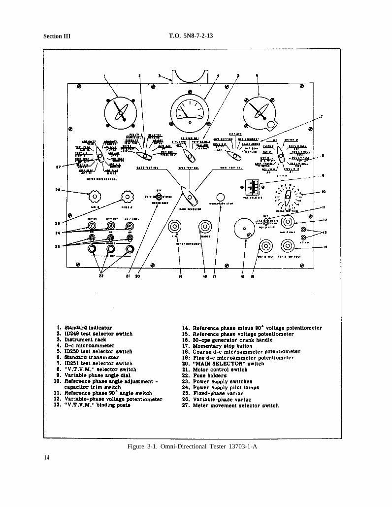
3-6. SETTING SYNCHRO ELECTRICAL ZERO.(See figure 3-1.)
a. Place the partially assembled Radio MagneticIndicator in rack (3) on top of the omnl-directionalinstrument tester 13703-1-A, Plug the ID250 testerconnector cable into the Radio Magnetic Indicator.
b. Set main selector switch (20) at “ID250 TESTSEL”.
c. Connect the three power sources (28-volt dc,117-volt 80 cps, and 115-volt 400-cps) to the instru-ment tester. Set power switches (24) at "ON".
d. Set the ID250 test, selector (5) switch at “DIALCARD".
e. Set standard transmitter (6) at zero degrees.
f. Loosen the radio magnetic indicator dial cardsynchro clamps, and carefully rotate the synchrountil the dial card zero is at the large pointer on themask. Tighten the clamps so the dial card aynchrois secured in the zero position.
g. Set ID250 test selector switch (5) at “POINTERNO. 1". Loosen the front hand assembly synchroclamps of the Radio Magnetic Indicator. Use theprocedure described in step f, and set the front handassembly of the Radio Magnetic Indicator on the 180
13
Section III T.O. 5N8-7-2-13
14
Figure 3-1. Omni-Directional Tester 13703-1-A
15
T.O. 5N8-7-2-13 Section III
degree position.
h. Set the ID250 test selector stitch at “POINTERNO. 2". Loosen the rear hand assembly synchroclamps of the Radio Magnetic Indicator. Use theprocedure described tn paragraph f, and set the rearhand assembly on the 180 degree position.
3-7. TESTING ASSEMBLED INDICATOR.
3-8. ROTATION AND SCALE ERROR TEST. (Seefigure 3-1.)
NOTE
Before performing this test, read paragraph3-9.
a. Place the assembled Radio Magnetic Indicator inrack (3) on top of the omni -directional instrumenttester 13703-1-A. Perform the procedures describedin paragraph 3-6, steps a through e. Set standardtransmitter (6) at exactly zero degrees. indicatormust read zero degrees (±0.75 degrees). Recordthe indicator reading.
b. Set standard transmitter (6) at exactly 30 degreesand record the reading of indicator. Continue re-setting the transmitter in 30-degree incrementsthrough its entire 360-degree range, recording theindicator reading after each new setting of the trans-mitter. No indicator reading taken during this testshould vary from the standard transmitter settingby more than 0.75 degree.
c. When all 13 settings (the zero-degree and 360-degree settings coincide) have been recorded, alge-braically add the differences between the standardtransmitter settings and the indicator readings anddivide the sum by 13. The answer should not exceed0.25 degree.
d. Set the ID250 test selector switch (5) at “POINT-ER NO. 1”, and set standard transmitter (6) at exactlyzero degrees. The Indicator must read 160 (30.75)degrees.
e. Repeat the procedure described in steps b and c,above, except that the 160-degree difference betweenstandard transmitter setting and indicator readingmust be subtracted each time to account for the 180-degree electrical zero relationship.
f. Set the ID250 test selector switch at “’POINTER
Paragraphs 3-7 to 3-10
NO. 2", and repeat steps d and e.
3-9. FRICTION ERROR TEST.
a. Tap the Radio Magnetic Indicator firmly butgently during each of the tests described in paragraph3-8 before turning the test selector swttch to thenext position.
b. The dial friction error of the Radio Magneticindicator should not exceed two degrees. The fric -tion error of the pointers should not exceed onedegree.
3-10. EVACUATING AND CHARGING INDICATOR.(See figure 2-1.)
a. Remove plastic cap nut (1), three screws (3),three lock washers (4), end cover (5) and nameplate(2).
b. Using the Hyper Vat. No. 25 vacuum pump inconjunction with hermetic sealing stand 13693-1-A,evacuate the instrument through the evacuation tubeon terminal assembly (21) to a pressure of 1 0 0microns or less. Check the gage on the hermeticsealing stand. When the pressure has been reached,shut off the evacuating pump, and fill the instrumentwith a mixture of 90-percent nitrogen and 10-percenthelium to a pressure of one atmosphere as read onthe hermetic sealing stand gage. Pinch off theevacuating tube approximately 1/4 inch from its end.Remove the instrument from the hermetic sealingstand and fill the end of the evacuating tube withsolder.
c. Immerse the indicator In a jar of water. The jarand airtight cover are included in the hermetic seal-ing stand. Reduce the absolute pressure of the airabove the water in the jar to approximately 1 in. Hg,and maintain the pressure until air bubbles sub-stantially cease to be given off by the liquid, orapproximately one minute, whichever is longer. In-crease the absolute pressure to 2-1/2 in. Hg. Bub-bles which come from within the indicator are con-sidered leakage, and the indicator must be recheckedfor air tightness. Correct the leakage, and repeatthe hermetic sealing procedure.
d. Upon successful completion of the leakage test,remove the indicator from the jar and dry thoroughly.Install end cover (5) and nameplate (2) with threelock washers (4) and three screws (3). Screw on theplastic cap nut (1).


This fine document...
Was brought to you by me:
Liberated Manuals -- free army and government manuals
Why do I do it? I am tired of sleazy CD-ROM sellers, who take publicly available information, slap “watermarks” and other junk on it, and sell it. Those masters of search engine manipulation make sure that their sites that sell free information, come up first in search engines. They did not create it... They did not even scan it... Why should they get your money? Why are not letting you give those free manuals to your friends?
I am setting this document FREE. This document was made by the US Government and is NOT protected by Copyright. Feel free to share, republish, sell and so on.
I am not asking you for donations, fees or handouts. If you can, please provide a link to liberatedmanuals.com, so that free manuals come up first in search engines:
<A HREF=http://www.liberatedmanuals.com/>Free Military and Government Manuals</A>
– SincerelyIgor Chudovhttp://igor.chudov.com/
– Chicago Machinery Movers