
TLM Technology for Off-Chip Interfaces on the …€¦ · Off-Chip Interfaces on the Automotive...
38
TLM Technology for Off-Chip Interfaces on the Automotive domain © Synopsys 2012 1 European SystemC User’s Group Workshop Victor Reyes Synopsys
Transcript of TLM Technology for Off-Chip Interfaces on the …€¦ · Off-Chip Interfaces on the Automotive...

TLM Technology for
Off-Chip Interfaces
on the Automotive domain
© Synopsys 2012 1
on the Automotive domain
European SystemC User’s Group Workshop
Victor Reyes
Synopsys

SoC
More than “SoC only” simulations
SystemBoard
© Synopsys 2012 2
IP
communication
Mobile, Consumer, Automotive, NetworkingDomain
device-to-device
communication
chip-to-chip
communication

• When moving to full system (device) simulations the interactions between* – Different chips on a device
– The device and the environment
*become more important
• A strategy to model and use the required (off-chip) interfaces that*– Enable the different players on the supply-chain to exchange models
The Challenge
© Synopsys 2012 3
– Enable the different players on the supply-chain to exchange models
– Take into account the requirements for systems beyond the SoC
* is required
• The scope of OSCI TLM-2.0 is limited to within the SoC (memory-mapped on-chip bus communication)
• Can the TLM-2.0 standard (or part of it) be reused to model bigger systems?

AgendaAgenda
Automotive Overview
TLM Serial Interface
© Synopsys 2012 4
TLM Serial Interface
Synopsys Solutions for Automotive
Summary

Automotive OverviewAutomotive Overview
© Synopsys 2012 5

Automotive E/E systems
• A car is a highly distributed computer system– High-end cars today can contain up to 100 ECUs
– More than 2000 individual SW functions in a car and increasing
– Automotive applications are distributed across multiple ECUs that communicate and interact with each other
© Synopsys 2012 6
• Dramatic increase in interdependencies and connection– e.g. going in reverse gear involves 10 ECUs
– one connector problem at Gateway ECU � 38 error messages in 5 ECUs
• Development and tests of such systems is very complex and costly
transmission
driver door
pass. door
parking aid
rear light
roof module
head unit
trailer
rearview
int. light back
int. light driver
int. light pass.
gateway
CAN bus
CAN bus

From Vehicle to SW
Vehicle Level
Subsystem Level
Vehicle SW
� 1 Billion lines of code by 2010
� > 2000 functions
� Distributed on 75 ECUs (average)
� Growing inter-dependencies
© Synopsys 2012 7
ECU Level
MCU Level
SW Level
Engine Control ECU (2005)
� 500-700 functions
� 5000+ pages of spec
� 200,000 lines of code
� 10-20,000 parameters

Elements in a Subsystem (terminology)
The Controlled system
(e.g. engine, transmission,
brakes, suspension, etc)
© Synopsys 2012 8
• Accelerator pedal position
•Transmission stage
• * ECU network
• Throttle valve
• Air mass
• Lambda oxygen sensor
•Crankshaft speed
• *
• Spark plugs
• Fuel injectors
• Throttle control
• *

In-Vehicle NetworkingCAN is the most spread network in the car, but has
limitations (1 Mbps, non-deterministic under high load >60%)
LIN is a low cost bus for body applications
(19.2 Kbauds, UART interface)
© Synopsys 2012 9
FlexRay is a high performance (10 Mbps), deterministic, and secure network
(mainly used in X-by-wire, ADAS, and high performance applications)
MOST is designed for multimedia
using optical fiber (up to 150 Mb/s)Ethernet mainly used for diagnostics
(but high potential in other areas)

Electronic Control Units (ECU) e.g. Powertrain Subsystem
• The core of a ECU is the main MCU (run the controller binary SW)
• Other components include:– Secondary MCU (8-bit) acting as external safety
watchdog, etc
– EEPROM
© Synopsys 2012 10
– EEPROM– Mixed-signal input and output conditioning blocks
– Dedicated ASIC (e.g. security)
• ECU components communicate with each other mainly using serial communication (SPI, I2C, *)
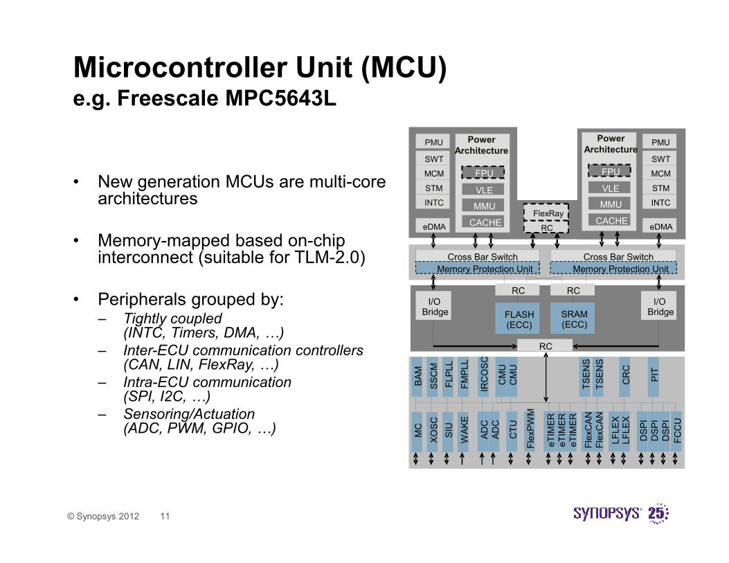
Microcontroller Unit (MCU)e.g. Freescale MPC5643L
• New generation MCUs are multi-core architectures
• Memory-mapped based on-chip interconnect (suitable for TLM-2.0) Cross Bar Switch
Memory Protection Unit
Cross Bar Switch
Memory Protection Unit
FlexRay
RC
FlexRay
RC
PMU
SWT
MCM
STM
INTC
eDMACACHE
Power
Architecture
MMU
VLE
CACHE
FPU
DebugDebug PMU
SWT
MCM
STM
INTC
eDMACACHE
MMU
VLE
CACHE
FPU
Power
Architecture
© Synopsys 2012 11
• Peripherals grouped by:– Tightly coupled
(INTC, Timers, DMA, 5)
– Inter-ECU communication controllers (CAN, LIN, FlexRay, 5)
– Intra-ECU communication (SPI, I2C, 5)
– Sensoring/Actuation (ADC, PWM, GPIO, 5)
I/OBridge
BA
M
RC RC
FLASH(ECC)
SRAM(ECC)
RC
I/OBridge
SS
CM
FLP
LL
FM
PLL
IRC
OS
C
CM
U
CM
U
CR
C
PIT
MC
XO
SC
SIU
WA
KE
TS
EN
S
TS
EN
S
AD
C
AD
C
CT
U
Fle
xP
WM
eT
IME
R
eT
IME
R
eT
IME
R
Fle
xC
AN
Fle
xC
AN
LF
LE
XLF
LE
X
DS
PI
DS
PI
DS
PI
FC
CU

TLM Serial InterfaceTLM Serial Interface
© Synopsys 2012 12

Objective
• Define a generic infrastructure that can be used to model
different off-chip interfaces
• Focus on serial interfaces (i.e. SPI, CAN, etc)
© Synopsys 2012 13
• Based on TLM technology
• That can serve as a basis for future standardization
Where to start?
• Understand off-chip serial interface communication
– Types, concepts, characteristics, 5
– Find common parts
• Understand how the SW interacts with off-chip interfaces
– What can be abstracted, what has to be modeled
© Synopsys 2012 14
– What can be abstracted, what has to be modeled
• Understand how the HW interacts with the off-chip interfaces
– Pin-multiplexing, SW controlled configuration, ..
• What the best implementation would be according to*
– Simulation speed, use-of-use, scalability, etc

Approach
Analyze characteristic
of serial Define the key requirements
Create an implementation
© Synopsys 2012 15
characteristic of serial
interfaces
Define the key requirements
Create an implementation

Indentify relevant interfaces
Plant
model
Plant
modelSensoring/actuation
PWM, ADC, GPIO
© Synopsys 2012 16
ECU
MCU
ECU
MCU
Intra-ECU communication
I2C, SPI
Inter-ECU communication
CAN, FlexRay, LIN

Serial interface (common) concepts
• Connectivity– Different topologies: point-to-point, bus, daisy chain, *
– Serial peripherals can have both the role of master (transmitter) and/or slave (receiver) dynamically over the same interface
• Communication– Synchronous (separated clock line) / asynchronous (local clock) communication
– Bidirectional full-duplex (simultaneous data send and receive)
– Bidirectional half-duplex (data send or receive but not simultaneously)
– Unidirectional
– Multi-master is a bus with more than one master (arbitration required)
– Multi-drop is an interface where there is one transmitter and several receivers (multicast)
© Synopsys 2012 17
– Multi-drop is an interface where there is one transmitter and several receivers (multicast)
– Multi-point is an multi-drop interface that allows bidirectional communication over the same set of wires
• Addressing (routing)– Communication can be unicast (single receiver), multicast (multiple receivers), broadcast (all connected nodes are
receivers)
– Dedicated lines can be used for the selection
– Addressing can be decided based on (partly) message decoding and filtering
• Arbitration– Bit-wise arbitration, dominant bit wins
• Acknowledge– Interleave response bit(s) from receiver on specific slots of transmitter message

SPI (serial peripheral interface)
• Connectivity– 4-wire (clock, slave select, data out, data in)
– Bus topology for data and clock
– Point-to-point for slave select
• Communication– Single-master
– Full duplex
– Synchronous
– Unicast
Intra-ECU communication
© Synopsys 2012 18
– Unicast
• Addressing– Dedicated slave select signal (master to slave)
• Arbitration– none
• Acknowledge– none
• Speed– Max. 70 MHz
• Other– Clock polarity (CPOL) and phase configuration
(CPHA) are relevant parameters (SW configured)
– Daisy chain bus configuration
– Not specific payload structure (or size)

CAN (controller area network)
• Connectivity– Differential-wires
– Bus topology
• Communication– Multi-master
– Broadcast
– Half-duplex
– Asynchronous
• Addressing
Inter-ECU communication
© Synopsys 2012 19
• Addressing– Filtering happens based on message ID
• Arbitration– Lower ID wins
• Acknowledge– Last bits of message
• Speed– Max. 1 Mbps
• Other– Different types of frames:
− Data frames (max. 108 bits)
− Remote frames (43 bits)
− Extended frames (128 bits)

Requirements
• Serial peripherals and busses are protocol specific (it should not be possible to connect e.g. CAN to SPI)– A generic infrastructure that can be specialized to different protocols will be defined
instead
– The generic infrastructure will include objects and rules to be used on the serial peripheral and bus models
– Keep the interface simple, handle protocol dependent details in the peripheral models and not in the interface (or bus)
• Focus on a single coding style (abstraction level)
© Synopsys 2012 20
• Focus on a single coding style (abstraction level)– Timed-accurate at the transaction boundary
– To be used on a LT or AT (with arbitration) platform
• The generic serial interface framework should support– Different types of routing: broadcast, multicast and unicast, over the same
implementation
– Synchronous and asynchronous communication
– Optional arbitration
– Enough timing information for the coding style
– Protocol specific information
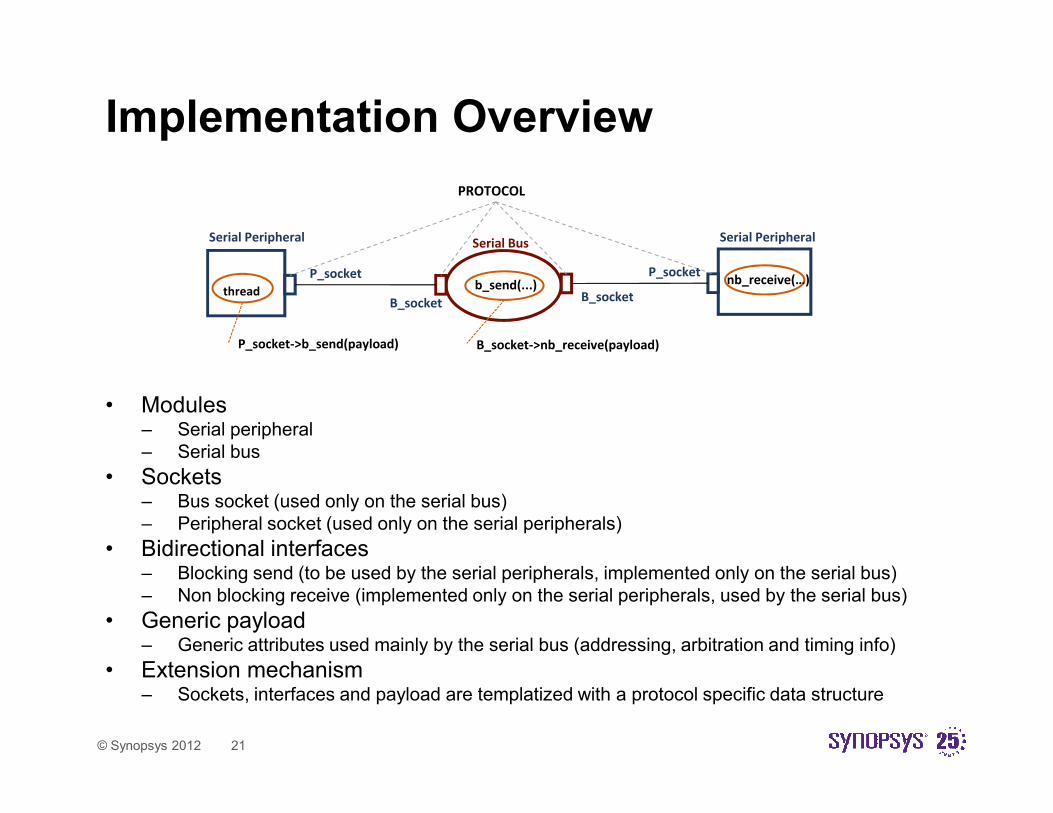
Implementation Overview
• Modules
PROTOCOL
thread
P_socket->b_send(payload) B_socket->nb_receive(payload)
b_send(...) nb_receive(…)P_socket P_socket
B_socketB_socket
Serial Peripheral Serial PeripheralSerial Bus
© Synopsys 2012 21
• Modules– Serial peripheral
– Serial bus
• Sockets– Bus socket (used only on the serial bus)
– Peripheral socket (used only on the serial peripherals)
• Bidirectional interfaces– Blocking send (to be used by the serial peripherals, implemented only on the serial bus)
– Non blocking receive (implemented only on the serial peripherals, used by the serial bus)
• Generic payload– Generic attributes used mainly by the serial bus (addressing, arbitration and timing info)
• Extension mechanism– Sockets, interfaces and payload are templatized with a protocol specific data structure

Generic Serial Payload
Attribute Data type Default value Description
routing_mask unsigned int 0 Value 0 � Broadcasting
Value 0xffffffff � Unicast (use select_id)
Any other value � Multicast (in combination with select_id)
This attribute is used by the serial bus.
select_id unsigned int 0 Indicates the destination port on the serial bus.
Not relevant when broadcasting.
This attribute is used by the serial bus.
arbitration_id unsigned int 0 Indicates the value to be used during arbitration.
This attribute is used by the serial bus.
prot_data_ptr T* 0 Pointer to the protocol specific data.
This attribute is used by the serial peripherals.
bit_length unsigned int 0 Length in bits of the data transmitted.
(select & mask) == (conn & mask)
© Synopsys 2012 22
bit_length unsigned int 0 Length in bits of the data transmitted.
Only used for timing calculation purposes.
This attribute is used by the serial peripherals.
clock sc_time 0 Indicates the serial clock used during the transmission
(synchronous protocols).
It can also used for error checking in asynchronous protocols.
This attribute is used by the serial peripherals.
status tlm_serial_response *see table below Indicates the status of the transmission.
More information in the table below.
This attribute is used by the serial bus and peripherals.
tlm_serial_response Description
TLM_SERIAL_OK Set by the receiver(s) to indicate successful reception of the transfer
TLM_SERIAL_ERROR Set by the receiver(s) to indicate a problem during the reception of the
transfer
TLM_SERIAL_INCOMPLETE Set by the transmitter. This is the default value. If the same value is
return indicates that no receiver has got the transfer
TLM_SERIAL_ARBITRATION_FAILED Set by the serial bus only. Indicates that arbitration failed and the
transmission did not take place completely.
struct tlm_serial_default_protocol {
unsigned int byte_lenght;
unsigned char* data_ptr;};

Bidirectional Serial Interfaces
class tlm_fw_serial_if : public virtual sc_core::sc_interface {
public:
virtual void b_send(tlm_serial_payload & payload) = 0;
};
The forward interface (b_send) is blocking. The rationale to make this interface blocking is to
enable its used within SC_THREAD (simplicity) and to enable optional arbitration on the serial
bus (serial bus may call sc_core::wait within the implementation) .
© Synopsys 2012 23
class tlm_bw_serial_if : public virtual sc_core::sc_interface {
public:
virtual void nb_receive(tlm_serial_payload & payload) = 0;
};
The backward interface (nb_receive) is non-blocking. That means that the serial peripherals
can NOT call sc_core::wait within the implementation. The rationale behind this decision is
to assure the correct timing on the communication when broadcasting or multicasting is
used.

Serial Peripheral Socket
template < typename PROTOCOL = tlm_serial_default_protocol >
class tlm_serial_socket : public tlm_base_serial_socket <PROTOCOL, tlm_fw_serial_if, tlm_bw_serial_if > {
public:
tlm_serial_socket() : tlm_base_serial_socket<PROTOCOL, tlm_fw_serial_if, tlm_bw_serial_if >()
{
}explicit tlm_serial_socket(const char* name) :
tlm_base_serial_socket<PROTOCOL, tlm_fw_serial_if, tlm_bw_serial_if >(name)
{
}
};
• The tlm_serial_socket is used in the serial peripherals ONLY
© Synopsys 2012 24
• This socket type enables bidirectional communication by using a sc_port and sc_export on the base class as standard TLM2 initiator sockets
• The socket uses the serial forward and backward interfaces described before
• The socket has also a template parameter named PROTOCOL. This parameter is used to enable the connection only between serial peripherals and busses that implement the same protocol

Serial Bus Socket
template < typename PROTOCOL = tlm_serial_default_protocol >
class tlm_serial_bus_socket : public tlm_base_serial_bus_socket<PROTOCOL, tlm_fw_serial_if, tlm_bw_serial_if > {
public:
tlm_serial_bus_socket() : tlm_base_serial_bus_socket<PROTOCOL, tlm_fw_serial_if, tlm_bw_serial_if >()
{
}
explicit tlm_serial_bus_socket(const char* name)
: tlm_base_serial_bus_socket<PROTOCOL, tlm_fw_serial_if, tlm_bw_serial_if >(name)
{
}
};
© Synopsys 2012 25
• The tlm_serial_bus_socket is used in the serial bus ONLY
• This socket type enables bidirectional communication by using a sc_export and sc_port on the base class as standard TLM2 target sockets
• The socket uses the serial backward and forward interfaces described before
• The socket has also a template parameter named PROTOCOL. This parameter is used to enable the connection only between serial peripherals and busses that implement the same protocol

Serial Bus (without arbitration)template< typename PROTOCOL = tlm_serial_default_protocol , int NoCONN = 2 >class tlm_serial_bus :
public sc_core::sc_module
, public tlm_fw_serial_if
{
public:
tlm_serial_bus_socket< PROTOCOL > *conn[NoCONN];
tlm_serial_bus(sc_module_name name): sc_core::sc_module(name){
…
}
void b_send(tlm_serial_payload & payload) {
tlm_serial_response default_rsp = TLM_SERIAL_INCOMPLETE;
unsigned int mask = payload.get_routing_mask();
unsigned int select = payload.get_select_id();
for(int c=0;c<NoCONN;c++) {
© Synopsys 2012 26
• Serial bus implements b_send and invokes nb_receive (twisted communication)
• Bus supports broadcast, multicast and unicast routing based on mask and select attributes
• Acknowledges are collected and returned to sender
for(int c=0;c<NoCONN;c++) {
if( (select & mask) == (c & mask) ) {(*conn[c])->nb_receive(payload);
if(payload.get_status() == TLM_SERIAL_ERROR) {
default_rsp = TLM_SERIAL_ERROR;
}
}
}
payload.set_status(default_rsp);
}
…
};

Serial Peripheral
• Reference implementation for a serial peripheral
• Serial peripherals will be protocol dependent – Protocol specific information is
described on the structure my_protocol
• TX thread can be activated by an internal event triggered by SW
struct my_protocol {
unsigned int id;
unsigned int data[2];
};
class tlm_serial_peripheral
: public sc_core::sc_module
, public tlm_bw_serial_if
{
public:
tlm_serial_socket< my_protocol > serial_port;
public:
SC_HAS_PROCESS(tlm_serial_peripheral);
tlm_serial_peripheral( sc_core::sc_module_name nm )
© Synopsys 2012 27
internal event triggered by SW through the register interface
• Since nb_receive is not blocking , for correct timing a separate SC_METHOD that handle the actions at the end of the message (e.g. set interrupts) triggered by an internal event can be used
tlm_serial_peripheral( sc_core::sc_module_name nm )
: sc_core::sc_module(nm)
, serial_port("serial_port")
{
serial_port(*this);
// TX THREADSC_THREAD(tx_thread);
sensitivity << activate_tx;
// RX METHOD
SC_METHOD(rx_method);
sensitivity << activate_rx;
}
private:my_protocol mSerialProtocol;
tlm_serial_payload tx_message;
sc_core::sc_time mSerialClk;
unsigned int storage[2];
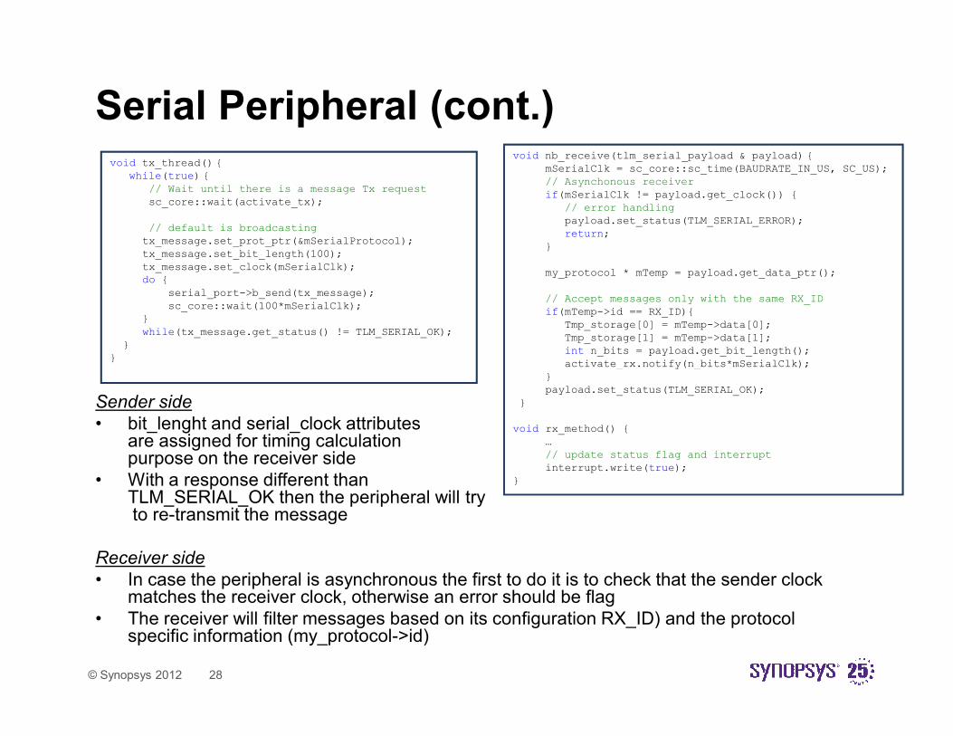
Serial Peripheral (cont.)void tx_thread() {
while(true) {
// Wait until there is a message Tx request
sc_core::wait(activate_tx);
// default is broadcasting
tx_message.set_prot_ptr(&mSerialProtocol);
tx_message.set_bit_length(100);
tx_message.set_clock(mSerialClk);do {
serial_port->b_send(tx_message);
sc_core::wait(100*mSerialClk);}
while(tx_message.get_status() != TLM_SERIAL_OK);
}
}
void nb_receive(tlm_serial_payload & payload) {
mSerialClk = sc_core::sc_time(BAUDRATE_IN_US, SC_US);
// Asynchonous receiver
if(mSerialClk != payload.get_clock()) {
// error handling
payload.set_status(TLM_SERIAL_ERROR);
return;
}
my_protocol * mTemp = payload.get_data_ptr();
// Accept messages only with the same RX_ID
if(mTemp->id == RX_ID){
Tmp_storage[0] = mTemp->data[0];
Tmp_storage[1] = mTemp->data[1];
int n_bits = payload.get_bit_length();
activate_rx.notify(n_bits*mSerialClk);
© Synopsys 2012 28
Sender side
• bit_lenght and serial_clock attributes are assigned for timing calculation purpose on the receiver side
• With a response different than TLM_SERIAL_OK then the peripheral will tryto re-transmit the message
Receiver side
• In case the peripheral is asynchronous the first to do it is to check that the sender clock matches the receiver clock, otherwise an error should be flag
• The receiver will filter messages based on its configuration RX_ID) and the protocol specific information (my_protocol->id)
activate_rx.notify(n_bits*mSerialClk);
}
payload.set_status(TLM_SERIAL_OK);
}
void rx_method() {
…
// update status flag and interrupt
interrupt.write(true);
}

Synopsys Solutions for AutomotiveSynopsys Solutions for Automotive
© Synopsys 2012 29

Model
Libraries
Component
Modeling
Assembly
HW/SW Debug
& Analysis Tools
Software Tool Interfaces
Design Tasks:
• SW-driven verification
• SoC HW/SW integration
Virtual Prototyping Development Flow
Virtual Prototyping Flow
© Synopsys 2012 30
Virtual Prototype Use
VDKs
Virtualizer: VP Creation
Block
Creation
Flows
Assembly
Debugging
Virtual
Prototype
Co-Simulation & External Connectivity
• SW development
• System validation & test
• Supply chain enablement
Model
Libraries
Component
Modeling
Assembly
HW/SW Debug
& Analysis Tools
Software Tool Interfaces
Design Tasks:
• SW-driven verification
• SoC HW/SW integration
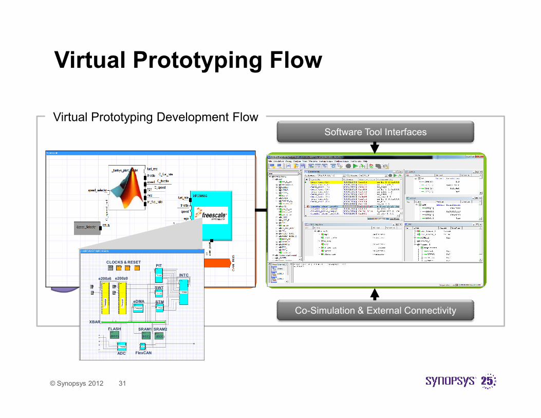
Virtual Prototyping Development Flow
Virtual Prototyping Flow
© Synopsys 2012 31
Virtual Prototype Use
VDKs
Virtualizer: VP Creation
Block
Creation
Flows
Assembly
Debugging
Virtual
Prototype
Co-Simulation & External Connectivity
• SW development
• System validation & test
• Supply chain enablement
CLOCKS & RESETPIT
SWT
STM
INTC
eDMA
e200z6 e200z0
XBAR
FLASH
(ECC)
SRAM1
(ECC)
SRAM2
(ECC)
FlexCANADC

Ecosystem
© Synopsys 2012 32
MCU Vendors
• Renesas
• Freescale
• Infineon
HLL Debuggers
• Lauterbach
• GreenHills
• PLS
• *
Physical Simulation
• Simulink
• Saber
Restbus
• CANoe

Debug and Analysis
3rd party
source code
debugger
Extra
Function,
instruction
tracing
Task,
event
tracing
© Synopsys 2012 33
Core #1 Core #2
I/OCAN
ADC
Timer
INTC
Memory
DMA
RTC
Host PC
Memory Memory
SPI
Break-/Watch-point
Visible Register
Visible Signal
Visible assembly code
Extra
visibility and
control with
VPA
Virtual
HW
model
I/O signal
tracing
Internal
pin and
register
tracing

Connectivity
Simulink SaberVirtual Prototype
© Synopsys 2012 34
VectorCustom tools

AgendaAgenda
Automotive Overview
TLM Serial Interface
© Synopsys 2012 35
TLM Serial Interface
Synopsys Solutions for Automotive
Summary

Summary
• Virtual prototyping is moving above the SoC level to full
system simulation
• There is a need to model (and standardize) off-chip interfaces
© Synopsys 2012 36
• TLM-2 cannot be applied “as is”, but it can serve as the
technology foundation
• Synopsys has prototyped a TLM serial interface framework
– To be used on automotive applications and according to automotive
requirements
– To be discussed with customers throughout the year

DemosDemos
© Synopsys 2012 37

Thank You
© Synopsys 2012 38


![Characterizing User Performance with Assisted Direct Off ...hci.cs.umanitoba.ca/...MobCHI-Barrett-offscreen.pdf · H5.2 [Information interfaces and presentation]: User Interfaces](https://static.fdocuments.us/doc/165x107/5ed2511ee0d2e942d71afe30/characterizing-user-performance-with-assisted-direct-off-hcics-h52-information.jpg)


