TITLE: Thread Roll Die Measurement Instructions SCOPE: RESPONSIBILITIES: It is the responsibility of...
6
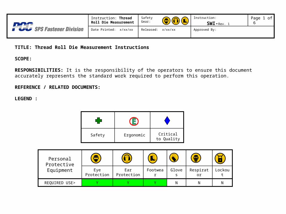
TITLE: Thread Roll Die Measurement Instructions SCOPE: RESPONSIBILITIES: It is the responsibility of the operators to ensure this document accurately represents the standard work required to perform this operation. REFERENCE / RELATED DOCUMENTS: LEGEND : N N N Y Y Y REQUIRED USE> Lockou t Respirat or Glove s Footwea r Ear Protection Eye Protection Personal Protective Equipment Approved By: Released: x/xx/xx Date Printed: x/xx/xx Page 1 of 6 Instruction: SWI-Rev. 1 Safety Gear: Instruction: Thread Roll Die Measurement Safety Ergonomic Critical to Quality
-
Upload
ernest-charity -
Category
Documents
-
view
213 -
download
0
Transcript of TITLE: Thread Roll Die Measurement Instructions SCOPE: RESPONSIBILITIES: It is the responsibility of...
TITLE: Thread Roll Die Measurement Instructions
SCOPE:
RESPONSIBILITIES: It is the responsibility of the operators to ensure this document accurately represents the standard work required to perform this operation.
REFERENCE / RELATED DOCUMENTS:
LEGEND :
NNNYYYREQUIRED USE>
LockoutRespiratorGlovesFootwearEar Protection
Eye Protection
Personal Protective Equipment
Approved By:Released: x/xx/xx
Date Printed: x/xx/xx
Page 1 of 6Instruction:
SWI-Rev. 1
Safety Gear:Instruction: Thread Roll Die Measurement
Safety Ergonomic Critical to Quality

DIAGRAM SEQ Step (what) SYM KEY POINTS (How & Why)
1.0 Prepare System for new Die
1. Using Handle, pull out die fixture
2. Remove any die that may have been left from previous scan
2.0 Prepare die for Scanning
1. Clean die, remove all debris with wire brush and compressed air.
3.0 Insert Die 1. Loosen Thumbscrew
2. Move Clamp
3. Insert die into Fixture
4. Make sure Die is flush into the corner of the fixture
Instruction:
Thread Roll Die Measurement
Safety Gear: Instruction:Page 2 of 6

DIAGRAM SEQ Step (what) SYM KEY POINTS (How & Why)
4.0 Secure Die 1. Move Clamp against Die
2. Tighten Thumb Screw
5.0 Move die into Position
1. Using Handle push die back until it is latched into place
6.0 Verify Laser is near home
position
1. Verify that each homing flag is with an inch or two from the home sensor.
2. If homing flags are not near the home sensors, use the Motor Step Program to move the laser into position.
3. Before using the Motor Step Program, Verify the laser will not run into the die.
Instruction: Thread Roll Die Measurement
Safety Gear: Instruction:
Page 3 of 6

DIAGRAMSEQ
Step (what) SYM KEY POINTS (How & Why)
7.0 Adjust laser Height 1. Adjust the laser to the correct height.
2. Loosen 4 set screws
3. Use the adjustment knob until the LED on top of laser is solid yellow or ideally green.
4. Level Laser to plane of die
5. Tighten 4 set Screws
8.0 Open Die Scanning Labview Application
1. Open application on computer
Instruction: Thread Roll Die Measurement
Safety Gear: Instruction:Page 4 of 6

DIAGRAM SEQ Step (what) SYM KEY POINTS (How & Why)
9.0 Select die Specifications
1. Input the die specification file location
2. Select the Die Size
3. Select Die Type
4. Select the Scan Type
5. Enable Toggle Switch
10.0 Set The resources
1. Select the correct serial ports for the Laser and Motion System
2. Enable the toggle switch
11.0 Specify Die
ID and file save location
1. Enter in the Die Identification number
2. Select the folder where the data file will be saved, using the current folder button
3. Enable the toggle switch
Instruction: Thread Roll Die Measurement
Safety Gear: Instruction:Page 5 of 6

DIAGRAM SEQ Step (what) SYM KEY POINTS (How & Why)
12.0 Home motors 1. Motors will automatically home after final toggle switch is pressed
13.0 Start Scan 1. Once the status message
reads “Begin Scan when Ready”, Press the Start Scan button to start the automated program.
2. Cycle time will range from 30 minutes to 2 hours depending on the scan type.
Instruction: Thread Roll Die Measurement
Safety Gear: Instruction:Page 6 of 6