Title: The Controlled Human Gyroscope
97
Title: The Controlled Human Gyroscope by Randy Claude Arjunsingh A thesis submitted to the College of Engineering Florida Institute of Technology in partial fulfillment of the requirements for the degree Masters of Science in Mechanical Engineering Melbourne, Florida July 2016
Transcript of Title: The Controlled Human Gyroscope

Title: The Controlled Human Gyroscope
by
Randy Claude Arjunsingh
A thesis submitted to the College of Engineering
Florida Institute of Technology
in partial fulfillment of the requirements for the degree
Masters of Science in Mechanical Engineering
Melbourne, Florida
July 2016

We the undersigned committee hereby approve the attached thesis, “The Controlled
Human Gyroscope” by Randy Claude Arjunsingh.
___________________________________________
Advisor: Dr. Matthew Jensen
Title: Assistant Professor
College: College of Engineering
_________________________________________________
Committee Member: Dr. Razvan Rusovici
Title: Associate Professor
College: College of Engineering
_________________________________________________
Committee Member: Dr. Ondrej Doule
Title: Assistant Professor
College: Human – Centered Design Institute
_________________________________________________
Department Head: Dr. Hamid Hefazi
Title: Professor
College: College of Engineering

iii
Abstract
Title: The Controlled Human Gyroscope
Author: Randy Claude Arjunsingh
Advisor: Matthew Jensen, Ph. D.
The objective of this thesis was to design an adaptive rotational motion simulator
capable of replicating the attitudes of spacecrafts and aircrafts, while avoiding gimbal
lock. Flight motion simulators are currently used for flight training and research, but
there are many limitations to these existing systems.
This thesis presents a low-cost design for a rotational motion platform titled, ‘The
Controlled Human Gyroscope’. It uses a 4-axis system instead of the conventional
3-axis system to avoid gimbal lock and prevent the unnecessary motion of the user.
The Human Gyroscope features unlimited rotation about the roll, pitch and yaw axes
regardless of the occupant’s orientation. It will therefore provide high fidelity motion
simulation and if it is paired with a translational motion platform, it can provide up
to 6 degrees of freedom. Equations of motion for this specific system are presented
in this paper and can be used to develop a control algorithm. A structural analysis on
the load bearing components of the simulator was performed in order to validate the
operating performance while maintaining a reasonable Factor of Safety. All these
components passed with the minimum factor of safety being 1.6 under the most
extreme loading conditions with most factors of safety above 2.9.

iv
Table of Contents
Table of Contents ................................................................................................... iv
List of Figures ........................................................................................................ vii
List of Tables .......................................................................................................... xi
Acknowledgement ................................................................................................. xii
Chapter 1 Introduction ............................................................................................ 1
1.1 Background and Motivation ......................................................................... 1
1.2 Purpose and Significance of Study ............................................................... 7
Chapter 2 Literature Review ................................................................................ 13
2.1 Existing Air and Space Craft Motion Simulators ..................................... 14
2.1.1 NASA Ames Vertical Motion Simulator ................................................ 14
2.1.2 Desdemona Motion Simulator ................................................................ 16
2.1.3 Aerotrim .................................................................................................. 19
2.1.4 The Human Gyroscope Project ............................................................... 20
2.2 Flight Simulation Fidelity ............................................................................ 22
2.3 Component Selection ................................................................................... 24
Chapter 3 Design and Methodology ..................................................................... 25

v
3.1 System Requirements................................................................................... 25
3.2 Overview of the Human Gyroscope’s Design ............................................ 26
3.3 Design Details of the Human Gyroscope .................................................... 27
3.2.1 Avoiding Gimbal Lock ........................................................................... 27
3.2.2 Motor Selection ....................................................................................... 29
3.2.3 Transferring Power/ Fluid through Rotating Components ..................... 32
3.2.4 Bearing Selection .................................................................................... 33
3.2.5 Designing a Compact System ................................................................. 35
3.2.6 Material Selection ................................................................................... 35
3.2.7 Supporting the Geared Ring .................................................................... 36
3.3 Torque Generation ....................................................................................... 38
3.3.1 Inner Ring ............................................................................................... 39
3.3.2 The Second Inner Ring............................................................................ 41
3.3.3 Toothed Ring ........................................................................................... 43
3.3.4 Final (duplicate) axis ............................................................................... 45
Chapter 4 Analysis ................................................................................................. 48
4.1 Structural Analysis ...................................................................................... 48
4.1.1 Inner Ring ............................................................................................... 50

vi
4.1.2 Second Inner Ring ................................................................................... 55
4.1.3 Gear Assembly ........................................................................................ 59
4.1.4 Final Axis ................................................................................................ 64
4.1.5 Supporting Structure ............................................................................... 67
4.2 Kinematic Analysis ...................................................................................... 68
4.2.1 Mathematical Description of Gimbal Lock............................................. 68
4.2.2 Four Axis System .................................................................................... 72
Chapter 5 Conclusion ............................................................................................ 76
5.1 Suggestions for Improvement ..................................................................... 78
References ............................................................................................................... 80

vii
List of Figures
Figure 1: The Sanders Teacher (Page 2000) .............................................................. 2
Figure 2: The Antoinette Simulator (Page 2000) ....................................................... 3
Figure 3: 3 DoF gimbal system ................................................................................ 10
Figure 4: 3 DoF gimbal lock situation ..................................................................... 11
Figure 5: Picture of the VMS at the NASA AMES Research Center (Terdiman 2009)
.......................................................................................................................... 15
Figure 6: Drawing showing the VMS and its motion systems (Alponso et al. 2009)
.......................................................................................................................... 16
Figure 7: The Desdemona Motion Simulator in Netherlands (Philippus Feenstra et
al. 2009)............................................................................................................ 17
Figure 8: Motion capabilities of the Desdemona Motion Simulator (Roza, Wentink,
and Feenstra 2007) ........................................................................................... 18
Figure 9: A 2 seater human gyroscope with a hydraulic motor ............................... 19
Figure 10: A 4 seater Human Gyroscope with an electric motor ............................. 20
Figure 11: A 3 dimensional rendering of the students design (Kjellin and Runevad
2012) ................................................................................................................ 21
Figure 12: Small Scaled Prototype for the study conducted at Halmstad University
(Kjellin and Runevad 2012) ............................................................................. 22

viii
Figure 13: 3D drawing showing the Human Gyroscope’s Design .......................... 26
Figure 14: 4 DoF gimbal lock situation ................................................................... 28
Figure 15: 4 DoF gimbal lock solution .................................................................... 29
Figure 16: Drawing showing size comparison between similar hydraulic (left) and
electric motors (3 on the right) from a top view .............................................. 30
Figure 17: Drawing showing the internals and general design of a Gerotor Hydraulic
Motor (Hahn 2013) .......................................................................................... 31
Figure 18: Drawing showing a Slip Ring (Fabricast INC 2016) ............................. 32
Figure 19: Dynamic Sealing Technologies Hydraulic 3 Passage Rotary Union with
an Integrated Slip Ring (Dynamic Sealing Technologies INC 2008) .............. 33
Figure 20: Picture showing the Controlled Human Gyroscope Turned on its side . 36
Figure 21: Picture of the Omnitrack Ball Transfer Unit .......................................... 37
Figure 22: Picture showing a side plate of the final axis with the thrust bearing and
the ball transfer units inserted .......................................................................... 37
Figure 23: Drawing of the internal ring of the Human Gyroscope .......................... 40
Figure 24: Drawing of the 2nd inner ring of the Human Gyroscope ........................ 42
Figure 25: Drawing of the toothed ring and 2 inner rings........................................ 44
Figure 26: Drawing of the final axis and all internal axes ....................................... 46
Figure 27: Ansys picture showing Equivalent Stress on the inner ring ................... 51

ix
Figure 28: ANSYS picture showing the minimum factor of safety for the inner ring
.......................................................................................................................... 52
Figure 29: ANSYS picture showing the Equivalent (von- Mises) Stress on the inner
ring with an offset internal mass ...................................................................... 53
Figure 30: ANSYS picture showing one of the force reactions on the inner ring ... 54
Figure 31: ANSYS picture showing Equivalent Stress on the 2nd inner ring .......... 56
Figure 32: ANSYS picture showing the minimum factor of safety for the second
inner ring .......................................................................................................... 57
Figure 33: ANSYS picture showing the Equivalent (von- Mises) stress on the second
inner ring with an offset center of mass ........................................................... 58
Figure 34: ANSYS picture showing the Total Deformation of the geared ring ...... 60
Figure 35: ANSYS picture showing the maximum stress on the gear assembly ..... 61
Figure 36: ANSYS picture showing the mesh refinement on the gear assembly .... 62
Figure 37: ANSYS picture showing a 63x scaled deformation plot of the gear
assembly ........................................................................................................... 63
Figure 38: Ansys picture showing the total deformation of the final axis ............... 65
Figure 39: Ansys picture showing factor of safety for the final axis ....................... 66
Figure 40: ANSYS picture showing a scaled plot of the total deformation of the final
axis ................................................................................................................... 66
Figure 41: ANSYS picture showing the total deformation of the stand .................. 67
x
Figure 42: ANSYS picture showing the area of concern of the stand analysis and the
Equivalent (von- Mises) Stress ........................................................................ 68
Figure 43: Drawing showing a 3DoF gimbal system .............................................. 69
Figure 44: Drawing of the Full 4-Axis Motion Simulator with Inertial Coordinate
System .............................................................................................................. 74
Figure 45: Picture showing the idler gears that can be added to provide additional
safety ................................................................................................................ 79

xi
List of Tables
Table 1: Table comparing the different types of hydraulic motors (Hahn 2013) .... 31
Table 2: Table showing a comparison between different types of bearings (Gonzalez
2015) ................................................................................................................ 34
Table 3: Table showing the specs of the chosen hydraulic motor ........................... 38
Table 4: Mass Estimate for Cockpit Components ................................................... 49
Table 5: Table showing the reaction moments and forces for the inner ring with the
center of mass in the middle of the structure ................................................... 54
Table 6: Table showing the reaction moments and forces for the inner ring with the
internal mass offset .......................................................................................... 55
Table 7: Table showing the force and moment reactions in the second inner ring with
the center of mass in the middle of the simulator ............................................ 58
Table 8: Table showing the force and moment reactions for the second inner ring
with an offset mass ........................................................................................... 59
Table 9: Table showing the force and moment reactions on the frictionless supports
of the big gear................................................................................................... 63

xii
Acknowledgement
I would first like to thank my thesis advisor Dr. Matthew Jensen of the Mechanical/
Aerospace Engineering department at Florida Institute of Technology. Dr. Jensen
was always available and very helpful throughout my entire project. He consistently
reviewed my work and resolved every problem I encountered while writing this
thesis.
I would also like to thank my committee members: Dr. Razvan Rusovici and Dr.
Ondrej Doule for taking the time to review my paper and listen to my thesis defense.
I am very grateful for Ms. Jennifer Nessmith from the Mechanical/ Aerospace
Engineering department office for assisting me from the time I entered this school
until now.
Finally, I must express my very profound gratitude to my parents for providing me
with unfailing support and continuous encouragement throughout my years of study
and through the process of researching and writing this thesis. This accomplishment
would not have been possible without them. Thank you.
Randy Arjunsingh

1
Chapter 1
Introduction
1.1 Background and Motivation
Prior to the existence of ground-based simulators, pilots learned to fly on actual
powered aircrafts. They would start as passengers in a plane for observation
purposes. Learning how to use the rudder was accomplished by taxiing a low
powered aircraft. A higher-powered machine would then be used to make short, then
long hops off the ground using the elevator control. The penguin system did exactly
this, but using a plane with a short wingspan. In an attempt to create a device that
would actually act like an aircraft, the Sanders Teacher (Figure 1) was invented,
which responded to aerodynamic changes.

2
Figure 1: The Sanders Teacher (Page 2000)
The Sanders Teacher simulator was made from aircraft components mounted on a
universal joint and placed in a headwind. The headwind would cause the system to
pivot about the universal joint when the ailerons, elevators or rudders were moved.
Changing wind conditions obviously presented issues with this system and it was
eventually rendered unreliable. Mechanical, human operated devices, such as the
Antoinette simulator (Figure 2) was capable of reproducing roll and pitch (Page
2000). The Antoinette simulator used two halves of a barrel that were mounted and
manually controlled.

3
Figure 2: The Antoinette Simulator (Page 2000)
With World War 1 increasing the demand for pilots, and as a result simulator
training, humans were replaced with electrical and pneumatic actuators capable of
changing the device’s attitude based on the control input by the user. Instructors had
the capability of inputting disturbances in the system to replicate wind changes.
Edwin Link developed the popular ground based flight simulator between the years
1927-1929 and patented it in 1930. The Link trainer included instruments so that the
user can monitor the simulator’s attitude and heading. Major advances in
computational technology during the World War II era propelled flight simulator
training as equations of motion were more easily solved. Although years of simulator
development continued, it was only in the 1960’s they became an integral part of
commercial flight training (Page 2000). Sending astronauts to the moon would have
been impossible without simulator training. The Lunar Landing Module led NASA
to the development of widely used motion equations in the simulation world. The
reason simulators exist is to familiarize humans with an unfamiliar environment or
situations. Many space and aviation accidents occurred because the pilot or astronaut
was in an unfamiliar situation whether he/she knew it or not.

4
Space flight mission debriefings, which are conducted post flight, have reported
numerous operational errors due to spatial disorientation on the International Space
Station (Clement and Bukley 1989). This phenomenon occurs when a person’s
perception of their orientation differs from their actual orientation. Roll, pitch and
yaw, which are rotational degrees of freedom associated with flight, are not familiar
modes of motion for a human. The Federal Aviation Administration (FAA) reports
that 90% of Spatial Disorientation accidents are fatal (Autunano 2003). Spacecraft
maneuvers are technical because for each motion in the low gravity environment,
thrusters are used for propulsion and turning. With this comes a significant delay,
which is unusual for an aviation pilot, however, this can be modeled and duplicated
in a motion simulator increasing pilot performance.
In the years 1991- 2000, Loss of Control of aircrafts contributed to 30% of accidents
worldwide and in 1990- 2001, 29.8% in the United States (Rogers et al. 2007).
According to Rogers et al, Uncontrolled Flight into Terrain accounted for 46% of
Australia’s general aviation accidents between 1991- 2000. Boeing Commercial
Airplanes reported that Loss of Control and Uncontrolled Flight into Terrain, made
up 33 of 72 (45.8%) fatal flight accidents between 2005 and 2014 (Boeing
Commercial Airplanes 2010).
The United States Department of Defense reported that defense cuts between the
years 2012 to 2021 could surpass one trillion dollars (Department of Defence 2015).
In the 2015 budget estimate, the Department of the Air Force indicated a 77.1 million
decrease in the flying hour program (Department of the Air Force 2014). The number
of hours a military pilot spends in a plane is therefore reduced and the demand for
realistic motion simulators increases. In a survey conducted by the Government
Business Council (GBC 2014), 34% of the United States Department of Defense

5
employees stated that the current training levels will not meet the military readiness
needs. With a reduction in the budget for the flying hour program, and an
accumulating need for training, flight simulation is quite valuable to the Air Force
and other national defense agencies. National Defense Industrial Association in a
2012 article reported that the Air Force estimates it could save about $1.7 billion over
five years by reducing flying hours by 5% and shifting more of its pilot and crew
training to simulators (Erwin 2012). For a Boeing 747, the cost of a level D simulator
operation to that of an actual aircraft is about 1:40 (Strachan 2000).
Cost can also come in the form of human life, especially when the model and
simulation affects the safety aspects of the simuland (Duncan 2007). Safety is a major
concern when conducting training exercises. Military training usually involves
testing the pilot or aircraft to their limits. Pilots in this situation are at a high risk and
accidents, however small, are very expensive compared to the operational costs of a
motion simulator.
It is currently not a requirement to have pilots experience inclement weather
conditions. In fact, these conditions are usually avoided by grounding flights or using
alternative paths. Pilots, however, can get caught in these situations and having prior
experience would be useful in avoiding unwanted incidents. Thunderstorms and
violent wind conditions are undoubtedly challenging situations for a pilot, especially
if it has not been encountered before. Between the years 2003-2007, weather related
accidents accounted for 1,740 cases or 20.1 % (Federal Aviation Administration
2010).
Discomforts such as lower back pain in middle to long range flights may cause pilots
to lose concentration affecting the safety of the flight (Goossens et al). Ergonomics

6
became so important that biomechanics and anthropometrics are studied subfields
used in the analysis of ergonomics in order for the creation of design guidelines.
These subfields help to describe the interaction between humans and machines
(Andrade 2013). Simulated environments and flight allow for valuable ergonomic
research and data collection. Better human- vehicle interfaces can be designed by
using prototypes in the motion simulator, before the part is mass-produced.
The National Aeronautics and Space Administration (NASA) conducts many
research projects that study human interaction with machines. Seeing that simulation
would be a crucial part of the flight industry, NASA developed their own flight
simulator that has been in operation since the 1970’s. Minor changes have been
made to the motion platform since then. Although their system works for simple
flight simulation, it is not capable of 360 degrees of rotation about any axis. The
Kennedy Space Center has a Human Gyroscope that rotates 360 degrees in three
different axes, but none of them is a controlled rotation. Having a simulator that has
controlled with unlimited roll, pitch and yaw motion, will undoubtedly broaden
research and training capabilities. The aeronautic and aerospace industry needs a
simulator that can properly replicate the rotational degrees of freedom that their
aircrafts possess.
It is clear that human error is a significant factor in aeronautical and aerospace
mishaps. Due to the limitations of current flight simulators, effective training
especially close to, or at an aircraft’s limit, has not yet been possible. A cost effective
training method capable of exposing pilots and astronauts to the mentioned situations
is a high fidelity, rotational motion simulator. Literature indicates that there is a lack
of flight simulators capable of the rotational motion envelope of a spacecraft or
aircraft.

7
1.2 Purpose and Significance of Study
Motion simulation provides a cheap and safe alternative to field training. It
submerges the operator into a virtual environment and synchronizes this virtual
motion with actual movement of the operator. Mistakes in the field can therefore be
avoided, situations can be accurately replicated and dangerous training situations no
longer have consequences, as they are not in an actual aircraft. Overall training cost
of pilots or astronauts is reduced significantly since operation and maintenance of a
simulator is cheaper than that of an actual vehicle. Less risk is involved while
operating a motion platform than a spacecraft or aircraft, so insurance and liability
costs are significantly reduced.
The School of Human- Centered Design, Innovation and Art at Florida Institute of
Technology proposed developing an adaptive spaceship cockpit motion simulator.
Its purpose was to serve as a low fidelity rotational motion simulator to simulate
human space flight. It needed to expose the human body to three-dimensional
rotational motion like the NASA human gyroscope that was originally designed to
train astronauts. Unlike NASA’s gyroscope, the vision of the project was to develop
a device that would have independently controlled, unlimited rotation, about all axes.
The Human Gyroscope needed to actively and independently control each axis of
rotation in order to replicate roll, pitch and yaw in any given orientation. With a
modular cockpit, different air or space crafts can be portrayed, therefore creating
environments that are congruent to the actual vehicle. While this rotational motion
platform was designed specifically to simulate spaceflight, there are many other uses.

8
Advanced and aggressive flight simulation can be conducted on this system. Most
existing dynamic flight simulators have limited rotational motion making them
inadequate in reproducing extreme flight situations. Even simple fixed wing Private
Pilot training exercises such as steep turns and stalls are difficult to mimic on limited
motion simulators. The angles that the system has to roll, pitch or yaw are simply too
much for the simulator to replicate. Unusual attitude recovery is an important part of
a pilot’s training. Situations arise in flight where visual flight rules are no longer
applicable. Such situations include flying: through clouds, at night or in inclement
weather. Unusual attitudes occur in these situations because the pilot is unable to use
visual cues to determine their orientation. The pilot may feel (based on other stimuli
like balance and gravity) like the aircraft is in straight and level flight, but this is not
always the case. The aircraft could be in a completely different orientation than
assumed by the pilot and dangerous situations can arise. The human gyroscope can
be used for training, while providing a safe, no consequence environment for the
operator.
Spatial disorientation is a contributing factor in many aviation accidents (Nooij and
Groen 2011). One of the main factors that contributed to the conceptualization of this
project is space motion sickness and disorientation. Piloted tasks such as docking
maneuvers and reentry or extravehicular tasks can be compromised due to motion
sickness (Stroud et al 2003). Motion simulators can be used as preventative action
for motion sickness and spatial disorientation. Stroud et al indicates that preflight
training in virtual reality devices that can closely replicate spacecraft movement will
reduce the incidence and/or severity of motion sickness and disorientation. A
person’s spatial awareness is determined by his/ her position, orientation and external
objects like buildings and other people. On earth, gravity and visual cues are the basis
for determining orientation. In certain conditions, such as spaceflight, these stimuli

9
become unreliable or unavailable (Stroud et al 2003) . When external factors and
gravity are removed, vision becomes the primary method for perceiving orientation.
This is not reliable as the subject would often be viewing things from an unfamiliar
angle. A person can be trained to adapt to these unfamiliar situations by undergoing
extensive motion simulator training.
The entertainment industry has an ever-growing need for motion simulators as rides
get more advanced and realistic. The rotational motion of the Human Gyroscope is
limitless and can therefore perform many duties for entertainment purposes. If the
simulator is added to a motion platform that can translate, like a rollercoaster track,
all 6 degrees of freedom will be unlocked.
Many motion simulators use the Stewart Platform as its source for motion. The
Stewart Platform (or hexapod) is a parallel device that consists of a platform
supported by six telescoping hydraulic or electronic struts (Van Silfhout 2001). The
platform is moved by changing the length of the telescoping struts. Changing the
length of one strut causes a realignment of all the struts which allows the platform to
have six degrees of freedom (Van Silfhout 2001). While this does provide six degrees
of freedom, its motion envelope is still very limited, typically to less than 45 degrees
of roll, pitch and yaw.
Limited motion is one of the issues phasing simulators today. Many simulators have
a limited range of motion and those that do offer unlimited rotation faces the issue of
gimbal lock. Gimbal lock or kinematic singularity occurs when two of the three axis
of a rotational system are driven into a collinear configuration. This results in the
loss of one degree of freedom (Jie and Qinbei 2015). We therefore lose either pitch,
roll or yaw. In order to achieve a high fidelity device, the system must be able to

10
avoid gimbal lock. While a 3-axis system can be controlled in such a way as to try to
avoid these locking positions, the fidelity of the system is lost because the operator
will undergo unnecessary movement while the system attempts to avoid locking
positions. Figure 3 is a drawing of a 3 degree of freedom gimbaled system where the
green ring controls pitch, the red ring controls yaw and the blue ring controls roll. If
the simulator is oriented as shown in Figure 4, for example, a 90-degree roll in a
spacecraft, one degree of freedom is lost. In this case, roll is duplicated and pitch is
lost.
Figure 3: 3 DoF gimbal system
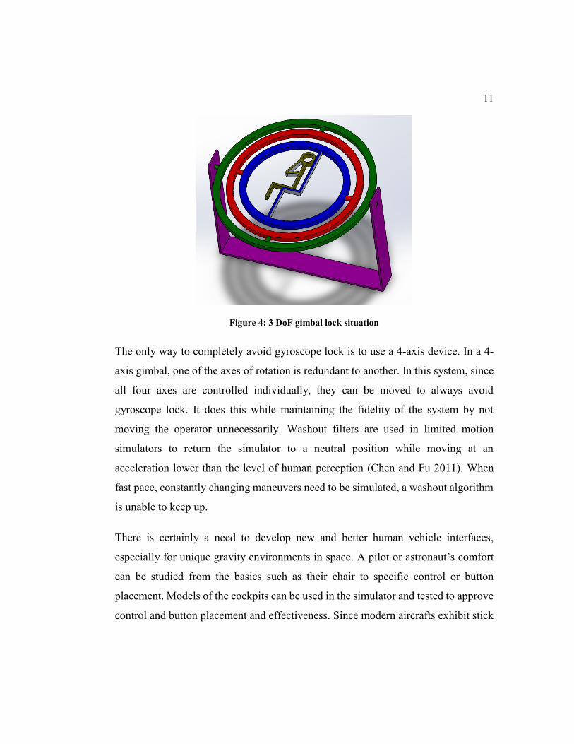
11
Figure 4: 3 DoF gimbal lock situation
The only way to completely avoid gyroscope lock is to use a 4-axis device. In a 4-
axis gimbal, one of the axes of rotation is redundant to another. In this system, since
all four axes are controlled individually, they can be moved to always avoid
gyroscope lock. It does this while maintaining the fidelity of the system by not
moving the operator unnecessarily. Washout filters are used in limited motion
simulators to return the simulator to a neutral position while moving at an
acceleration lower than the level of human perception (Chen and Fu 2011). When
fast pace, constantly changing maneuvers need to be simulated, a washout algorithm
is unable to keep up.
There is certainly a need to develop new and better human vehicle interfaces,
especially for unique gravity environments in space. A pilot or astronaut’s comfort
can be studied from the basics such as their chair to specific control or button
placement. Models of the cockpits can be used in the simulator and tested to approve
control and button placement and effectiveness. Since modern aircrafts exhibit stick

12
fixed stability using hydraulic actuation devices, they are required to have force
feedback systems. Operator interactions with the control and feedback system can
also be studied using a motion simulator. Simply examining these cases in a static
environment is only half of what needs to be done. Analyzing and surveying pilots
in dynamic simulation devices can provide crucial information about the design of
the cockpit, placement of controls and operator- machine interaction.

13
Chapter 2
Literature Review
The spinning mass gyroscope is one of the most common types of gyroscopes in
existence today. A conventional spinning mass gyroscope contains a rotating disk or
wheel that uses its inertial properties to resist any change in direction of its moment
(Mario et al 2013). This device was first invented in 1852 by Leon Foucault, while
investigating and demonstrating how the earth rotates (Biography.com 2015).
There are many uses for gyroscopes today, but they are primarily used in inertial
navigation systems. The reason for this is because the principle of angular
momentum follows closely to Newton’s first law, which says: a body at rest will
remain at rest or a body in motion will stay in motion unless acted upon by an external
force. The angular momentum of a system will remain unchanged (conserved) unless
acted upon by an external torque. Since this holds true for gyroscopes, their inertial
properties allow them to be effectively used in navigation systems.
Human gyroscopes, which are similar to spinning mass gyroscopes, were later
developed for medical purposes and astronaut training. They have the ability to
contain a human and rotate about two or three axes. These gyroscopes were also used
to simulate the feeling of tumbling in space. Our design, which is discussed later in
this paper, is a modified version of a human gyroscope that will act as a 3 degree of
freedom, rotational motion simulator.
Aside from being a cheaper, safer alternative to field testing, motion simulators are
capable of accurately and repeatedly replicating specific situations. Concentrated
14
testing and training of pilots and astronauts are conducted on existing flight
simulators. As discussed previously, flight simulators have a long history and new
developments still exist today. Motion simulators that are in use today usually
possess advanced software and hardware integration, but none of them is capable of
avoiding gimbal lock without unnecessary movement of the pilot.
2.1 Existing Air and Space Craft Motion Simulators
2.1.1 NASA Ames Vertical Motion Simulator
The NASA Ames Vertical Motion Simulator (VMS), shown in Figure 5, is the largest
flight based motion simulator in existence today (Advani et al 2002). It has an
interchangeable cabin (I- CAB) that allows the users to replicate the interior of
different spacecrafts or aircrafts.
15
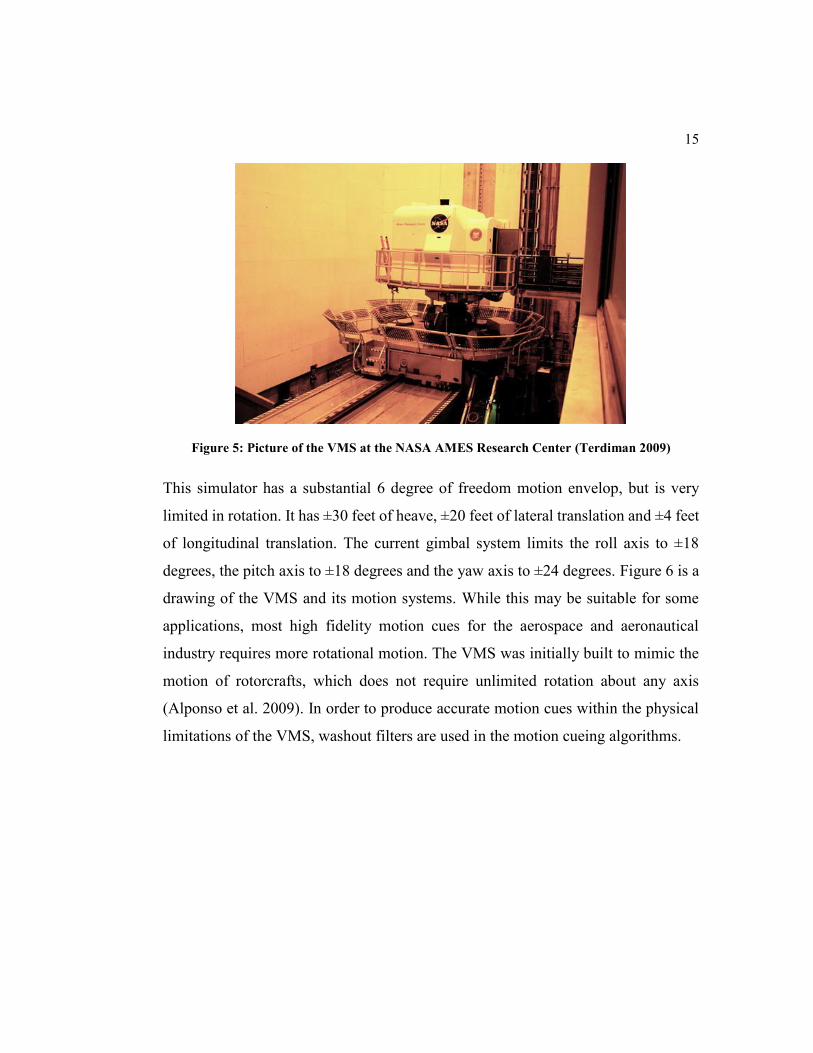
Figure 5: Picture of the VMS at the NASA AMES Research Center (Terdiman 2009)
This simulator has a substantial 6 degree of freedom motion envelop, but is very
limited in rotation. It has ±30 feet of heave, ±20 feet of lateral translation and ±4 feet
of longitudinal translation. The current gimbal system limits the roll axis to ±18
degrees, the pitch axis to ±18 degrees and the yaw axis to ±24 degrees. Figure 6 is a
drawing of the VMS and its motion systems. While this may be suitable for some
applications, most high fidelity motion cues for the aerospace and aeronautical
industry requires more rotational motion. The VMS was initially built to mimic the
motion of rotorcrafts, which does not require unlimited rotation about any axis
(Alponso et al. 2009). In order to produce accurate motion cues within the physical
limitations of the VMS, washout filters are used in the motion cueing algorithms.

16
Figure 6: Drawing showing the VMS and its motion systems (Alponso et al. 2009)
2.1.2 Desdemona Motion Simulator
The most advanced human gyroscope known to man today is the Desdemona motion
simulator developed by TNO Human Factors and AMST in 2007. Figure 7 is a
picture of the actual system located in the Netherlands. This system offers unique
motion simulation not seen anywhere else in the world (Roza et al 2007).
Current motion simulators suffice for basic training, but they are not capable of
exactly replicating complex motion due to their limited motion envelope. When
situations become unpredictable or extreme, like in military aircrafts, ground vehicle
accidents and rollovers, emergency maneuvers or spaceflight, standard motion
simulators are not very useful.

17
Figure 7: The Desdemona Motion Simulator in Netherlands (Philippus Feenstra et al. 2009)
Unlike other simulators, the Desdemona allows unlimited rotation about any axis
because the cabin of the Desdemona is supported by a fully gimbaled system. This
gimbal, consisting of right-angled concentric rings, is mounted on a mechanism
capable of heaving it over 2 m. The heave mechanism and thus the entire system can
move over 8m on a horizontal track. The track can rotate itself to generate up to a
sustained 3 g load. The Desdemona therefore mimics 6 degrees of freedom within its
motion envelop; however, the development of motion driving algorithms is complex.
The degrees of freedom for the Desdemona motion simulator is depicted in Figure 8.
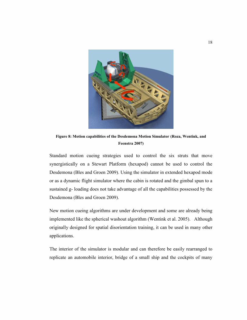
18
Figure 8: Motion capabilities of the Desdemona Motion Simulator (Roza, Wentink, and
Feenstra 2007)
Standard motion cueing strategies used to control the six struts that move
synergistically on a Stewart Platform (hexapod) cannot be used to control the
Desdemona (Bles and Groen 2009). Using the simulator in extended hexapod mode
or as a dynamic flight simulator where the cabin is rotated and the gimbal spun to a
sustained g- loading does not take advantage of all the capabilities possessed by the
Desdemona (Bles and Groen 2009).
New motion cueing algorithms are under development and some are already being
implemented like the spherical washout algorithm (Wentink et al. 2005). Although
originally designed for spatial disorientation training, it can be used in many other
applications.
The interior of the simulator is modular and can therefore be easily rearranged to
replicate an automobile interior, bridge of a small ship and the cockpits of many

19
aircrafts including helicopters and spacecraft. The Desdemona can be used by the
aerospace, aviation, automotive and entertainment industry, among others.
2.1.3 Aerotrim
An Aerotrim is a gyroscope large enough to contain a human and they are used for
cardiovascular workouts, entertainment and astronaut training. This device was
initially developed for medical purposes specifically to relieve back pain. Since a
human physically controls it, it was later used as an exercise machine. For stretching,
aerobics, strength training, core workouts and improving coordination and balance,
the rider shifts his/ her body weight to rotate different rings of the gyroscope.
There are many existing variations of Aerotrims, but none have full control about
each axis of rotation. Some modern Human Gyroscopes today are powered either by
an electric or hydraulic motor, but only one axis is controlled.
Figure 9: A 2 seater human gyroscope with a hydraulic motor

20
Figure 9 shows a picture of a two seater human gyroscope with a hydraulic motor.
This particular gyroscope has only 2 degrees of freedom and the inner ring is left to
tumble due to its dynamic center of gravity. The outer ring is spun with the hydraulic
motor, which changes the position of the center of gravity shifting the system out of
equilibrium. Figure 10 is a similar system that seats four riders and uses an electric
motor instead of a hydraulic motor to control the external gimbal.
Figure 10: A 4 seater Human Gyroscope with an electric motor
2.1.4 The Human Gyroscope Project
The Human Gyroscope project presented by Halmstad University is similar in
concept to our design. It is a motor driven simulator that copies the design of a
rotating mass gyroscope (Kjellin and Runevad 2012). Their device features three
degrees of rotational freedom, but since there are only three gimbals, it is possible

21
that it would encounter gyroscope lock. Figure 11 is a three-dimensional rendering
of the student’s design.
If this simulator has to replicate a vehicle pitching up 90 degrees, the roll axis is
duplicated by the yaw axis and yaw motion is therefore lost. Even when the simulator
approaches 90 degrees, true yaw motion is no longer attainable. The motion will be
a mixture of roll and yaw. This lowers the fidelity of the simulation, as unnecessary
or incorrect movement of the operator will happen in this orientation.
Figure 11: A 3 dimensional rendering of the students design (Kjellin and Runevad 2012)
Transferring power and signals to the internal motors of the simulator was a
significant challenge but it was overcome by using electrical slip rings. The goal of
their thesis was, to design and build a prototype of a motion simulator that is unique
and has unlimited rotation about one or more axes. Figure 12 is a picture of the small-
scaled prototype that was built at Halmstad University.

22
Figure 12: Small Scaled Prototype for the study conducted at Halmstad University (Kjellin
and Runevad 2012)
2.2 Flight Simulation Fidelity
Major airlines are currently conducting their recurrent, initial, transition and upgrade
training entirely on flight simulators and they have practically eliminated training
accidents at airlines that use high fidelity simulators (Burki-cohen, Go, and
Longridge 2001). When pilots complete their simulator training, they are required to
complete a supervised Initial Operating Experience. At this point, the trainees are
entrusted with the safety of the passengers on the airplane. For a motion platform
flight simulator to be effective, it is critical and absolutely necessary for the cues to
transfer performance and behavior characteristics for the aircraft being simulated
(Burki-Cohen and Go 2005). For a motion cue to even be considered valid, it should

23
never lead the visual cues. Synchronized roll and lateral motion cues are allowed to
lag but it should not be more than 40ms (Chung and Johnson 1997).
Flight simulators are evaluated and classified by an FAA Simulator Evaluation
Specialist. The ones that do not move are given numeric assignments: Level 1 to
Level 7 with Level 7 being the most sophisticated (Marsh 2011). The ones that have
a motion platform, are grouped into 4 classes: Level A (visual), Level B (Phase I),
Level C (Phase II) and Level D (Phase III) (Federal Aviation Administration 1991).
Simulator complexity increases from A to D. The high fidelity NASA AMES
Vertical Motion Simulator, shown earlier in this study, is a Level D flight simulator.
In a study conducted on the Desdemona Motion Simulator, participants indicated that
having the motion and forces made the simulation more realistic and helped them
conduct their tasks better versus having no motion and forces.
All FAA qualified full flight simulators are required to have a motion base and their
effectiveness for new pilot and recurrent training is well recognized (Longridge et al.
2001). Subject matter experts from industry, academia and FAA indicated that the
absence of a motion platform on flight simulators is likely to have a detrimental effect
on pilot control performance especially in maneuvers that require sudden motion
with limited visual references. It is clearly important from literature that flight
simulators should have a high fidelity motion platform that is capable of closely
synchronizing physical motion with the users input into the virtual system.

24
2.3 Component Selection
Part of the requirement for this thesis project was to have a complete functional
design for the motion simulator. In doing this, design choices had to be made on
components of the entire assembly. Materials, motors and bearings were some of the
main items of concern, among others.
For our motion simulator, hydraulic motors were selected over electric motors for a
number of different reasons. Hydraulic motors are small, compact mechanical
devices that generate steady, continuous torque (rotary motion), directly from the
hydraulic system (Aeronautics Learning Labrotory 2004). These were all attractive
features for our design. Since each axis had to be independently controlled, power
needed to be transferred through the rotating components to the inner axes. This
proved to be one of the more challenging parts of the design. To resolve this issue,
rotary hydraulic unions with internal slip rings were selected to transfer hydraulic
fluid and electrical power. These are similar to the rotary manifolds used on
excavators.
Chromium- molybdenum (Chromoly) is a high carbon steel that is primarily used to
produce tubing for bicycles and race cars. Though it is not as light as aluminum
alloys, it has a higher tensile strength and malleability (Woodcock 2013). To form
the circular rings of the Human Gyroscope, tubes will have to be bent into shape so
malleability is crucial. Chromoly is also durable and corrosion resistant making it a
great choice for our motion simulator. Chapter 3 goes into much more detail on why
these design choices were made.

25
Chapter 3
Design and Methodology
3.1 System Requirements
The major tasks of the Controlled Human Gyroscope were to mimic a spacecraft’s
launch, landing, reentry, atmospheric flight and microgravity flight. The operator
should have unlimited rotation about the roll, pitch and yaw axes at any given time
and hence avoid gimbal lock. The vector sum of the tangential accelerations at the
user’s head should be at least 0.2 G’s, but up to 2 G’s. The system needed to
accommodate an analog space suit and a Primary Life Support System (PLSS)
backpack. The armrests, leg and head support should be adjustable in length and
position since the system should accommodate 95 US percentile male/female. One
of the most challenging requirements was to make the simulator as compact and as
light as possible. In order to have a diverse motion simulator, the cockpit had to be
modular where equipment could be switched out to represent different vehicles. The
internal seat structure should be completely removable in the event that it needs to
be updated. The cockpit must be powered either by battery or by AC power. The
entire structure needs to comply with ISO26262 which is a functional safety
standard. The internal mass to be supported, not including the rotational rings or
motors, should be 250kg (including the max operator weight of 120kg). For the
cockpit to contain all the necessary equipment for simulation, the internal ring
(cockpit area) must have a minimum diameter of 1980mm.

26
3.2 Overview of the Human Gyroscope’s Design
The most basic form of our design is that of a spinning disc gyroscope. While our
design looks similar to an Aerotrim, the functionality is very different. Instead of
being physically powered by a human, every axis is individually controlled by
hydraulic motors. The controlled human gyroscope has four gimbals, and therefore
four degrees of rotational freedom, where one is redundant to avoid gimbal lock. The
inner ring has a diameter of 2032mm, which meets the requested design
requirements. Figure 13 is a 3D drawing of our Human Gyroscope without its
internal components. The operator will be seated in the inner ring (blue) and each
ring will control an axis of rotation.
Figure 13: 3D drawing showing the Human Gyroscope’s Design

27
3.3 Design Details of the Human Gyroscope
3.2.1 Avoiding Gimbal Lock
Most motion simulators have a limited range in replicating roll, pitch and yaw. Those
that are capable of continuous rotation about every axis are likely to encounter gimbal
lock. As mentioned before, gimbal lock occurs when two axes of rotation become
collinear. When this happens, rotating any one of those axes will produce the same
motion (either roll, pitch or yaw). One degree of freedom is therefore forfeited or in
other words, the operator has lost one of his/ her rotation axes. Depending on which
two axes line up, the operator will no longer be able to either roll, pitch or yaw them.
It is important for gimbal lock to be avoided to maintain a high fidelity simulation.
Figure 14 is a drawing of a four degree of freedom system in a gimbal lock
configuration. In this instance, the simulator is replicating a 90-degree roll as seen
above in Figure 4. Similarly to the three DoF gimbals, pitch is lost here as well.

28
Figure 14: 4 DoF gimbal lock situation
The only way to combat gimbal lock with the three DoF system is to use special
motion cueing algorithms with washout filters. These filters help the system return
to a neutral position or in other words, return to an orientation where roll, pitch and
yaw can be simulated. As discussed before, this results in unnecessary movement of
the operator and the algorithm may not be able to follow along with aggressive
simulation. The four DoF gimbals possess the exact same properties as the design
used in this project. Software on the system will detect when a potential gimbal lock
situation is approaching and instead of moving to a neutral location, the fourth axis
will move to avert this problem. Figure 15 shows how the motion simulator will
move to maintain control of roll, pitch and yaw. The green ring now controls pitch,

29
the red ring controls yaw, the blue ring controls roll and yaw is duplicated with the
yellow axis.
Figure 15: 4 DoF gimbal lock solution
3.2.2 Motor Selection
Hydraulic and electric motors are both used in the simulation industry. Each have
their own pros and cons. Electric motors are capable of instantaneously generating
torque while hydraulic motors have a delay. Hydraulic motors are often selected
because of packaging constraints and torque requirements. In the case of this project,
a motor that is capable of generating sufficient torque while fitting tight packaging
constraints was needed. To keep the system compact, hydraulic motors were
selected. Figure 16 shows the size comparison between the motors from a top view.

30
These motors were chosen to generate the required torque as they were all capable
of the same RPM and were all seven horsepower motors.
Figure 16: Drawing showing size comparison between similar hydraulic (left) and electric
motors (3 on the right) from a top view
There are five main types of hydraulic motors, each designed for different
applications. The human gyroscope required high torque, high speed, compact,
relatively low cost and reversible hydraulic motors. Gerotor motors (Figure 17)
perfectly fit this description and was selected over the other types shown in Table 1
(Hahn 2013).The flow path of these motors control its direction of motion. The
hydraulic pump used to pump fluid can reverse the flow path and hence the motor’s
direction.
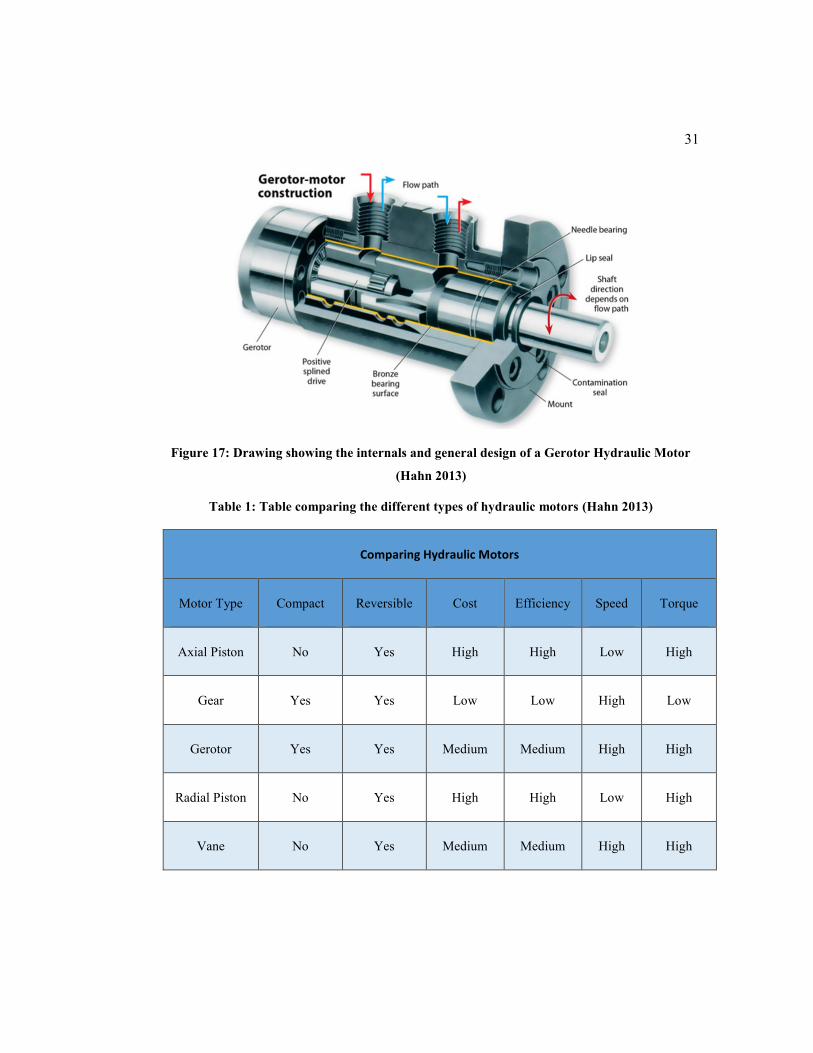
31
Figure 17: Drawing showing the internals and general design of a Gerotor Hydraulic Motor
(Hahn 2013)
Table 1: Table comparing the different types of hydraulic motors (Hahn 2013)
Comparing Hydraulic Motors
Motor Type Compact Reversible Cost Efficiency Speed Torque
Axial Piston No Yes High High Low High
Gear Yes Yes Low Low High Low
Gerotor Yes Yes Medium Medium High High
Radial Piston No Yes High High Low High
Vane No Yes Medium Medium High High
32
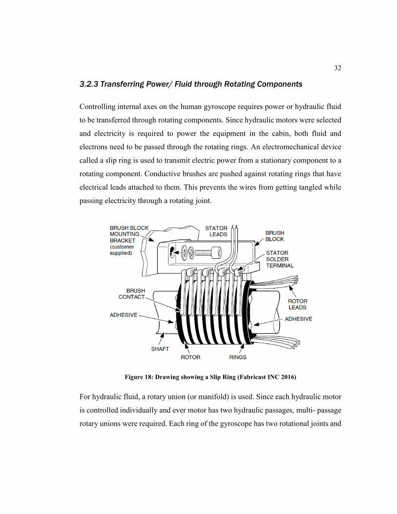
3.2.3 Transferring Power/ Fluid through Rotating Components
Controlling internal axes on the human gyroscope requires power or hydraulic fluid
to be transferred through rotating components. Since hydraulic motors were selected
and electricity is required to power the equipment in the cabin, both fluid and
electrons need to be passed through the rotating rings. An electromechanical device
called a slip ring is used to transmit electric power from a stationary component to a
rotating component. Conductive brushes are pushed against rotating rings that have
electrical leads attached to them. This prevents the wires from getting tangled while
passing electricity through a rotating joint.
Figure 18: Drawing showing a Slip Ring (Fabricast INC 2016)
For hydraulic fluid, a rotary union (or manifold) is used. Since each hydraulic motor
is controlled individually and ever motor has two hydraulic passages, multi- passage
rotary unions were required. Each ring of the gyroscope has two rotational joints and

33
a motor is placed on one of these joints for control. Electric power and hydraulic
fluid needed to both be transmitted through the other rotating joint. Dynamic Sealing
Technologies Inc. is a company that manufactures rotary unions that have the option
for an integrated slip ring (Figure 19). Their unions contain multiple independent
fluid passages allowing for the individual control of each motor. With this union,
continuous rotation of either attached component is allowed.
Figure 19: Dynamic Sealing Technologies Hydraulic 3 Passage Rotary Union with an
Integrated Slip Ring (Dynamic Sealing Technologies INC 2008)
3.2.4 Bearing Selection
Bearings are used in the design to allow for rotation and reduce friction. The two
main types of mechanical bearings that are used in this design are radial and thrust
bearings. The names explain the types of loads that the bearings are designed to
endure. Radial loads are perpendicular to the axis of rotation and axial loads are
parallel to the axis of rotation. Within these two categories of bearings, there exists
spherical and roller bearings. Spherical or ball bearings are the most common type
of bearing used in mechanical components (Hamrock and Anderson 1980).

34
Cylindrical roller bearings are used in higher capacity loading cases and can be either
thrust or radial bearings. Table 2 shows a concise comparison between the different
types of bearings and what they are best used for. The Controlled Human Gyroscope
uses cylindrical roller thrust and radial bearings. The thrust bearings support the drive
gear’s weight when the system is flipped on its side.
Table 2: Table showing a comparison between different types of bearings (Gonzalez 2015)
Bearing Comparison
Bearing Type Sub Type Radial Thrust
Ball Bearing Conrad Type Good Fair
Self-aligning Fair Fair
Cylindrical Roller Bearing Separable inner ring non-locating Excellent 0
Self-contained 2 direction locating Good Poor
Tapered Roller Bearing Self-aligning Excellent Poor
Spherical Roller Bearing Self-aligning Excellent Good
Thrust Bearings Single direction ball, grooved race Poor Excellent
Single direction eye roller 0 Excellent
Needle Bearing Complete Good 0

35
3.2.5 Designing a Compact System
When a concentric ring is added to the system, the integration of motors and the
rotary union must be taken into account. Every time a ring is added, approximately
1 foot (12 inches) of space must be left on each side to incorporate the mentioned
components. Avoiding gimbal lock requires four axes of rotation, which relates to
four concentric rings. In this scenario, only one motor is allowed per ring, which
creates torque limitations making the system incapable of generating enough g-
forces on the operator. In order to make the system compact while allowing for
additional motors on external rings, a geared ring was used.
3.2.6 Material Selection
The Human Gyroscope Motion Simulator rotates a human about three axes of motion
with a combined g- force of at least 0.2 G’s. Safety is a major concern, so the
materials selected needed to be strong, rigid but at the same time lightweight. For the
rings of the gyroscope, tubes were chosen instead of solid stock in order to save
weight. Round tubing was then chosen over square tubing due to the strength to
weight ratio. Chromoly 4130 was selected over plain carbon steel because of its
higher Ultimate Tensile strength and Yield Strength. The round Chromoly tubes used
in our design have a 2-inch outer diameter and a 0.25-inch wall thickness. This
material is readily available in numerous size configurations and extremely
manufacturable. Standard structural steel was selected for all the other components
on the simulator. Steel is also easily obtained and relatively cheap.

36
3.2.7 Supporting the Geared Ring
When the motion simulator is turned on its side (Figure 20), the gears will have the
potential to slip past each other due to gravity. In order to support these gears and the
weight of the entire system, specialty bearings were used. The smaller drive gears
are supported by cylindrical thrust bearings on each side. The bigger, driven gear
proved to be more of a challenge to support. High capacity ball transfer units were
used to hold the gear in place. These ball transfer units contain ball bearings that
allow the top sphere to rotate. The gear can then slide freely over these units with
minimum friction. Figure 21 is a picture of the Omnitrack ball transfer unit.
Figure 20: Picture showing the Controlled Human Gyroscope Turned on its side

37
Figure 21: Picture of the Omnitrack Ball Transfer Unit
A total of 20 ball transfer units were inserted into the side plates of the final axis and
this is shown in Figure 22. This figure also shows the thrust bearing used to support
the smaller drive gear.
Figure 22: Picture showing a side plate of the final axis with the thrust bearing and the ball
transfer units inserted

38
3.3 Torque Generation
The selected hydraulic motors are compact but can generate a substantial amount of
torque. Table 3 shows the specs of the motor selected for this project.
Table 3: Table showing the specs of the chosen hydraulic motor
Hydraulic Motor Model- 6299K55
Horsepower 7.3
Torque 3,141 in.-lbs
Max RPM 147
Max Flow 12 gpm
Fixed Displacement 17.9
cu.in/rev
Max Pressure 1400 psi
Overall Length 9"
Shaft Length 1.52"
Shaft Diameter 1"
Keyway Width 1/4"
Keyway Depth 1"
Using some of these basic numbers, calculations were done to ensure that the torque
specifications were met. The vector sum of the tangential accelerations at the user’s

39
head should be at least 0.2 G’s, but up to 2 G’s. Calculating tangential acceleration
at the user’s head required us to calculate angular acceleration. Angular acceleration
however, is a function of the object’s moment of inertia (tendency to resist angular
acceleration). Inertia is calculated based on the objects size and shape so to simplify
this process; moments of inertia were calculated and obtained using Solidworks. A
250kg spherical ball (2 times the weight limit) was added to the internal ring to
simulate the components that would be later added to the simulator.
3.3.1 Inner Ring
The inner ring has a diameter of 2.03m and spins about the x-axis as shown in Figure
23. It was important to include the 250kg of mass that will be housed in this ring
before obtaining the moment of inertia. When calculating the acceleration at the
head, the dimensions for a 50th percentile male was used. An assumption was made
that the person’s seat will be at the center of rotation.

40
Figure 23: Drawing of the internal ring of the Human Gyroscope
The calculations were completed as follows:
𝐼𝑥𝑥 = 49.33 𝑘𝑔.𝑚2 (3.1)
𝜏 = 𝐼𝑥𝑥 ∗ ∝ (3.2)
𝜏𝑚𝑜𝑡𝑜𝑟 = 3141 𝑖𝑛. 𝑙𝑏𝑠 = 354.9 𝑁.𝑚 (3.3)
Using equations 3.1, 3.2 and 3.3:
∝ =𝜏
𝐼𝑥𝑥=
354.9
49.33= 7.19
𝑟𝑎𝑑
𝑠2(3.4)
At the person’s head, 0.77m away from center of rotation, the tangential acceleration
was calculated as follows:

41
𝑎 = 𝑟 ∗∝ (3.5)
𝑎 = 0.77 𝑚 ∗ 7.19𝑟𝑎𝑑
𝑠2= 5.54
𝑚
𝑠2(3.6)
Acceleration at head in terms of G’s:
𝑎 =5.54
9.81= 0.56 𝐺′𝑠 (3.7)
The first ring is therefore within the limits of the g- force requirements. The motor
for the inner ring can be attached to a planetary gear to adjust the torque or max rpm
of the system.
3.3.2 The Second Inner Ring
The second inner ring has a diameter of 2.7m and spins about the y-axis as shown in
Figure 24. The internal mass (250kg) and the mass and size of the inner ring were
taken into account when computing the moment of inertia for the second ring.

42
Figure 24: Drawing of the 2nd inner ring of the Human Gyroscope
The calculations were completed as follows:
𝐼𝑦𝑦 = 113.8 𝑘𝑔.𝑚2 (3.8)
𝜏 = 𝐼𝑦𝑦 ∗ ∝ (3.9)
𝜏𝑚𝑜𝑡𝑜𝑟 = 3141 𝑖𝑛. 𝑙𝑏𝑠 = 354.9 𝑁.𝑚 (3.10)
From equations 3.8, 3.9 and 3.10:
∝ =𝜏
𝐼𝑦𝑦=
354.9
113.8= 3.12
𝑟𝑎𝑑
𝑠2(3.11)

43
At the person’s head, 0.77m away from center of rotation, the tangential acceleration
was calculated as follows:
𝑎 = 𝑟 ∗∝ (3.12)
𝑎 = 0.77 𝑚 ∗ 3.12𝑟𝑎𝑑
𝑠2= 2.40
𝑚
𝑠2(3.13)
Acceleration at head in terms of G’s:
𝑎 =2.40
9.81= 0.24 𝐺′𝑠 (3.14)
The second ring is therefore within the limits of the g- force requirements. The motor
for the second inner ring can be attached to a planetary gear to change max torque
and rpm.
3.3.3 Toothed Ring
The toothed ring has a diameter of 3.5m and spins about the z-axis as shown in Figure
25. The internal mass (250kg) and the mass and size of the two inner rings were taken
into account when computing the moment of inertia for the toothed ring. The toothed
ring can be controlled by up to four motors. For these calculations, two motors were
used. It should also be noted that the gear ratio could be changed by altering the drive
gear.

44
Figure 25: Drawing of the toothed ring and 2 inner rings
The calculations were completed as follows:
𝐼𝑧𝑧 = 951 𝑘𝑔.𝑚2 (3.15)
𝜏 = 𝐼𝑧𝑧 ∗ ∝ (3.16)
𝜏𝑚𝑜𝑡𝑜𝑟 = 3141 𝑖𝑛. 𝑙𝑏𝑠 = 354.9 𝑁.𝑚 (3.17)
𝑇𝑜𝑟𝑞𝑢𝑒 𝑢𝑠𝑖𝑛𝑔 2 𝑚𝑜𝑡𝑜𝑟𝑠 = 354.9 ∗ 2 = 709.8 𝑁.𝑚 (3.18)
𝐺𝑒𝑎𝑟 𝑟𝑎𝑡𝑖𝑜 (𝑑𝑟𝑖𝑣𝑒𝑛: 𝑑𝑟𝑖𝑣𝑒) = 11.7: 1 (3.19)
Using equations 3.18 and 3.19:
𝑇𝑜𝑟𝑞𝑢𝑒 𝑎𝑝𝑝𝑙𝑖𝑒𝑑 𝑡𝑜 𝑑𝑟𝑖𝑣𝑒𝑛 𝑔𝑒𝑎𝑟 = 11.7 ∗ 709.8 = 8304.7𝑁.𝑚 (3.20)

45
Rearranging equation 3.16 and substituting equations 3.20 and 3.15:
∝ =𝜏
𝐼𝑦𝑦=
8304.7
951= 8.73
𝑟𝑎𝑑
𝑠2(3.21)
At the person’s head, 0.77m away from center of rotation, the tangential acceleration
was calculated as follows:
𝑎 = 𝑟 ∗∝ (3.22)
𝑎 = 0.77 𝑚 ∗ 8.73𝑟𝑎𝑑
𝑠2= 6.72
𝑚
𝑠2(3.22)
Acceleration at head in terms of G’s:
𝑎 =6.72
9.81= 0.69 𝐺′𝑠 (3.24)
The toothed ring is therefore within the limits of the g- force requirements.
3.3.4 Final (duplicate) axis
In order to follow the compact design requirement, the final axis is not an additional
ring. The entire assembly of rings can further be rotated around the y-axis as shown
in Figure 26. This duplicate axis can also be used to control the roll, pitch or yaw of
the user depending on the orientation. This fourth axis of rotation will, however,
primarily be used to avoid gimbal lock (depending on the control algorithm). Since
this axis does not have tight space limitations like the internal axes, larger or
additional motors can be used. Four motors identical to the ones used in the rest of

46
the system were used. The gears controlling this axis can be altered to change max
torque or rpm.
Figure 26: Drawing of the final axis and all internal axes
The calculations were completed as follows:
𝐼𝑦𝑦 = 492.75 𝑘𝑔.𝑚2 (3.25)
𝜏 = 𝐼𝑦𝑦 ∗ ∝ (3.26)
𝜏𝑚𝑜𝑡𝑜𝑟 = 3141 𝑖𝑛. 𝑙𝑏𝑠 = 354.9 𝑁.𝑚 (3.27)
𝑇𝑜𝑟𝑞𝑢𝑒 𝑢𝑠𝑖𝑛𝑔 4 𝑚𝑜𝑡𝑜𝑟𝑠 = 354.9 ∗ 4 = 1419.6 (3.28)

47
Rearranging equation 3.26 and substituting equations 3.28 and 3.25:
∝ =𝜏
𝐼𝑦𝑦=
1419.6
492.75= 2.88
𝑟𝑎𝑑
𝑠2(3.29)
At the person’s head, 0.77m away from center of rotation, the tangential acceleration
was calculated as follows:
𝑎 = 𝑟 ∗∝ (3.30)
𝑎 = 0.77 𝑚 ∗ 2.88𝑟𝑎𝑑
𝑠2= 2.22
𝑚
𝑠2(3.31)
Acceleration at head in terms of G’s:
𝑎 =2.22
9.81= 0.23 𝐺′𝑠 (3.32)
The final axis is also therefore within the limits of the g- force requirements even
though this will primarily be used to avoid gimbal lock. This axis was set up this way
for flexibility when the control algorithms are developed. The person developing
these algorithms can use this axis to avoid gimbal lock or control the roll, pitch or
yaw of the user depending on orientation.

48
Chapter 4
Analysis
4.1 Structural Analysis
ANSYS Workbench was the program chosen to run the Finite Element Analysis
(FEA) on the components of the Human Gyroscope. Situations that could potentially
cause the system to fail, such as applying maximum torque to the system from a
stationary position, were analyzed. This caused the structural members to undergo
the maximum amount of stress that can be applied by the system. The Static
Structural function was used in ANSYS since its purpose was to determine stresses,
displacements, etc. under static loading conditions. It is accurate to assume that the
instant maximum torque is applied to the stationary system, a static loading condition
exists.
The ideal Human Gyroscope, having four degrees of rotational freedom, should
ideally have its center of mass and center of rotation aligned. The center of rotation
(CoR) occurs where all four axes of rotation intersect. It was intentional that the CoR
be exactly located in the center of the rings. The center of mass is still undetermined
and variable as the internal components of the human gyroscope were not a part of
the design requirements. The School of Human- Centered Design, Innovation and
Art at Florida Institute of Technology will design the simulator’s cockpit. It was
important however, to include the 250kg of mass in the internal ring for the
simulation. The mass estimates for the components and user are shown in Table 4.
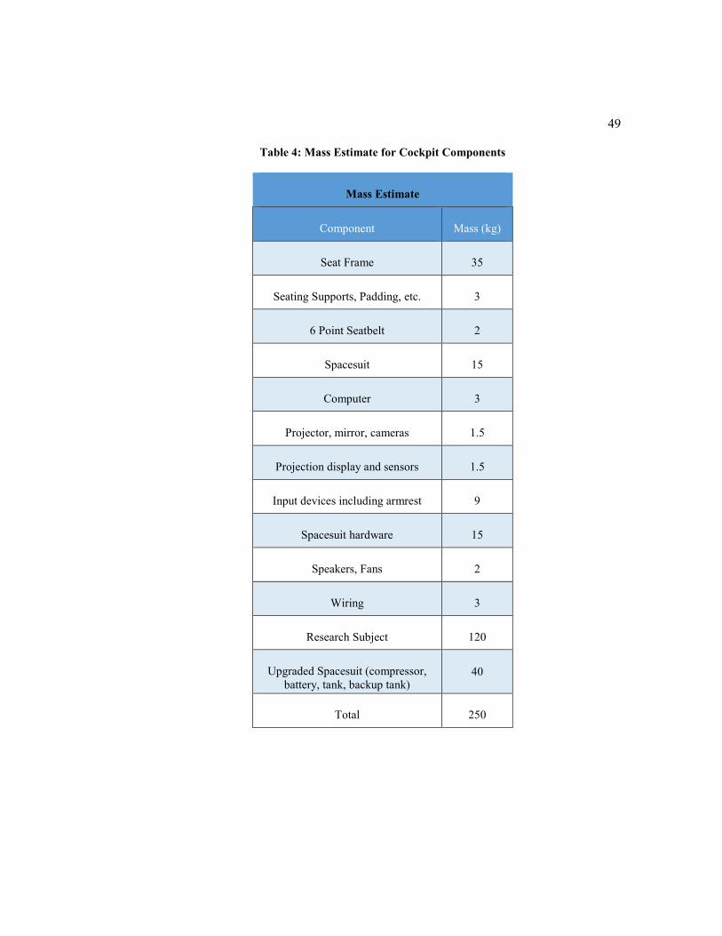
49
Table 4: Mass Estimate for Cockpit Components
Mass Estimate
Component Mass (kg)
Seat Frame 35
Seating Supports, Padding, etc. 3
6 Point Seatbelt 2
Spacesuit 15
Computer 3
Projector, mirror, cameras 1.5
Projection display and sensors 1.5
Input devices including armrest 9
Spacesuit hardware 15
Speakers, Fans 2
Wiring 3
Research Subject 120
Upgraded Spacesuit (compressor,
battery, tank, backup tank) 40
Total 250

50
As mentioned before, a sphere with a mass of 250kg was used to represent the
components in the cockpit. For the initial analysis, this sphere was placed at the
center of the internal ring. This placed the center of mass of the system very close to
the center of rotation. The sphere was then offset from the center to the lower left
quadrant of the inner ring so that the centers of mass and rotation do not align. The
new center of mass measured 0.2 meters from the CoR. This was an arbitrarily
selected position used to study the effects of an offset center of mass. The selected
position however was an overestimation of an offset center of mass because in
reality, the cockpit will be designed to keep the centers of mass and rotation aligned.
Operators of the Controlled Human Gyroscope will have unique weight distributions
and the center of mass will change with every user. This change can be kept to a
minimum by placing the user’s seat close to the CoR. The actual center of mass of
the Gyroscope and user should never exceed the selected position (measured radially
outward from the CoR). A second static structural analysis was done on this modified
setup. The center of mass measured in Solidworks of the Gyroscope (without the
stand and interior) was: X = -0.01m, Y = 0.02m and Z = 0.09m.
4.1.1 Inner Ring
The inner ring was analyzed first as this provided input information for the second
inner ring. The standard earth gravitational force feature was used to simulate gravity
acting in the positive x direction (down in this case). Since the rings were being
analyzed individually, supports were added to simulate the mounting points for the
rings. The maximum torque that the hydraulic motor can deliver was applied to the
ring. Remote displacement supports were used on both ends of the ring with all
degrees of freedom set to zero, except rotation about the axis where the moment was

51
being applied. This was done in order to replicate a ‘worst case’ situation. The default
mesh was first used to generate ballpark solutions and then the mesh was refined
around areas of concern. On this ring, the rotary union mount and motor attachment
were the areas of concern. Force reaction and moment reaction probes were placed
at the supports so that this data can be used in the next analysis.
Figure 27: Ansys picture showing Equivalent Stress on the inner ring
Normalized Chromoly 4130 was used for the inner ring and the maximum equivalent
(von-Mises) stress sustained is 90.3 MPa as shown in Figure 27. Upon closer
examination of the area of concern (area with the maximum stress or lowest factor
of safety), it was noted that the connection point between the flange and the ring
undergoes the most stress. This is an area that would already be welded together by

52
design and thicker weld beads can strengthen this particular part. The lowest factor
of safety was 4.8. The area of concern is shown in Figure 28.
Figure 28: ANSYS picture showing the minimum factor of safety for the inner ring
When the internal mass of the gyroscope was offset, changes were noted in
deformation, equivalent stress, force reactions and moment reactions. Although the
deformation and stress was higher, it was not significant enough to compromise the
parts. Figure 29 shows how the mass was offset and the new equivalent stress on the
member. Initially, the maximum equivalent stress was 90.3MPa; however, with the
offset mass, it increased to 95MPa. Additionally, the factor of safety decreased from
4.8 to 4.6 with the minimum value in the same location for both instances.

53
Figure 29: ANSYS picture showing the Equivalent (von- Mises) Stress on the inner ring with
an offset internal mass
The second inner ring supports the first ring at two connection points: the motor and
rotary union connection. Forces and moments will then be transferred from the inner
ring to the second inner ring through these two connection points. In ANSYS,
reaction probes were placed at these supports so that the forces and moments
transferred could be calculated. These values were then used in the analysis of the
second inner ring so that the inner ring could be removed. For example, Figure 30
shows the reaction force at the bottom of the inner ring. Since gravity acts downward
in this picture, the weight had to be supported against gravity. The reaction force
pointed up and away from gravity to keep the body static. The second inner ring
provided this reaction force. Table 5 displays the values obtained from the force and
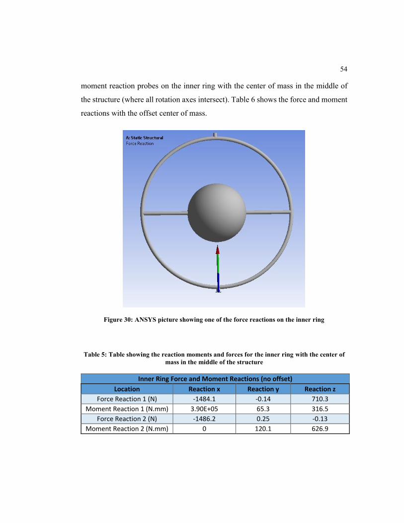
54
moment reaction probes on the inner ring with the center of mass in the middle of
the structure (where all rotation axes intersect). Table 6 shows the force and moment
reactions with the offset center of mass.
Figure 30: ANSYS picture showing one of the force reactions on the inner ring
Table 5: Table showing the reaction moments and forces for the inner ring with the center of
mass in the middle of the structure
Inner Ring Force and Moment Reactions (no offset)
Location Reaction x Reaction y Reaction z
Force Reaction 1 (N) -1484.1 -0.14 710.3
Moment Reaction 1 (N.mm) 3.90E+05 65.3 316.5
Force Reaction 2 (N) -1486.2 0.25 -0.13
Moment Reaction 2 (N.mm) 0 120.1 626.9

55
Table 6: Table showing the reaction moments and forces for the inner ring with the internal
mass offset
Inner Ring Force and Moment Reactions (offset)
Location Reaction x Reaction y Reaction z
Force Reaction 1 (N) -1485.3 -172.68 0
Moment Reaction 1 (N.mm) 3.90E+05 31 -3.20E+04
Force Reaction 2 (N) -1484.9 172.7 0
Moment Reaction 2 (N.mm) 0 25.13 -4.07E+04
4.1.2 Second Inner Ring
The second inner ring was also analyzed individually because using less
computational resources allows ANSYS to display solutions quicker. Since this ring
supports the inner ring, the reaction forces and moments from the previous analysis
were used in place of the first ring. Similarly to the first analysis, ballpark solutions
were generated with the standard mesh and the mesh was refined mainly around the
areas of concern. Normalized Chromoly 4130 was also used for this ring and the
maximum equivalent (von-Mises) stress was 147.1 MPa as shown in Figure 31.
56
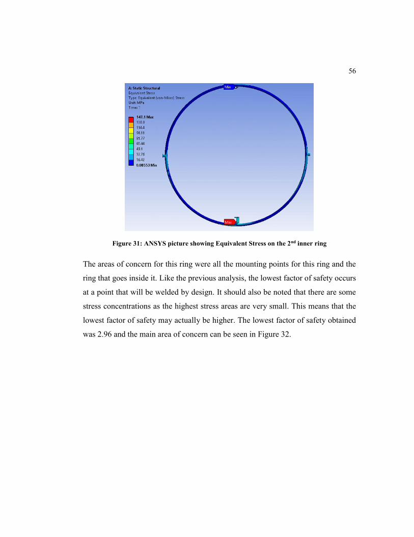
Figure 31: ANSYS picture showing Equivalent Stress on the 2nd inner ring
The areas of concern for this ring were all the mounting points for this ring and the
ring that goes inside it. Like the previous analysis, the lowest factor of safety occurs
at a point that will be welded by design. It should also be noted that there are some
stress concentrations as the highest stress areas are very small. This means that the
lowest factor of safety may actually be higher. The lowest factor of safety obtained
was 2.96 and the main area of concern can be seen in Figure 32.

57
Figure 32: ANSYS picture showing the minimum factor of safety for the second inner ring
Data was taken from Table 6 (offset center of mass) and input into another static
structural analysis for the second inner ring. Again, changes were noted but none
were significant enough to compromise the part. Figure 33 shows that the maximum
equivalent stress did change, but only by 1.3MPa.

58
Figure 33: ANSYS picture showing the Equivalent (von- Mises) stress on the second inner ring
with an offset center of mass
Since this ring is also supported by another ring, the gear in this case, reaction forces
and moments were computed at the supports. Table 7 lists the force and moment
reactions at the supports without an offset internal mass. Table 8 displays the same
data but with an offset mass. The values from these tables were used as inputs in the
analysis of the gear assembly.
Table 7: Table showing the force and moment reactions in the second inner ring with the
center of mass in the middle of the simulator
2nd Inner Ring Force and Moment Reactions (no offset)
Location Reaction x Reaction y Reaction z
Force Reaction 1 (N) 1232.8 -7.5 153.5
Moment Reaction 1 (N.mm) 2.25E+04 0 2.20E+05
Force Reaction 2 (N) 1236.2 7.5 -153.5
Moment Reaction 2 (N.mm) 2.23E+04 3.61E+05 -2.10E+05

59
Table 8: Table showing the force and moment reactions for the second inner ring with an
offset mass
2nd Inner Ring Force and Moment Reactions (offset)
Location Reaction x Reaction y Reaction z
Force Reaction 1 (N) 1336.9 -3.2 153.5
Moment Reaction 1 (N.mm) 2.25E+04 0 2.76E+05
Force Reaction 2 (N) 1054.6 3.5 -153.5
Moment Reaction 2 (N.mm) 2.23E+04 3.60E+05 -1.50E+05
The force and moment reaction values here had a very small change from a centered
mass to an offset mass. As the analysis moved from the inner ring outward, the
change in force and moment values between an offset mass and a centered mass
decreased. Using the offset mass values in the next analysis produced equal results
so only one of them will be reported.
4.1.3 Gear Assembly
The material selected for this ring was structural steel as it is readily available and
relatively cheap. The analysis for this ring was more challenging than the rest. The
assembly of gears were imported into the analysis and the rest of the structure
replaced with relevant supports. Figure 34 is a picture of the Total Deformation in
millimeters experienced by the gears. Frictionless supports were used on the sides of
the gear to allow them to slide but not move out of plane. Moments were applied to
the smaller gears that would rotate the bigger gear in a clockwise motion. Remote
displacements were used on the small drive gears and all the parameters set to zero
except rotation around the axis where the torque is applied. Another remote
displacement was used on the driven gear (bigger gear) completely fixing it in space.
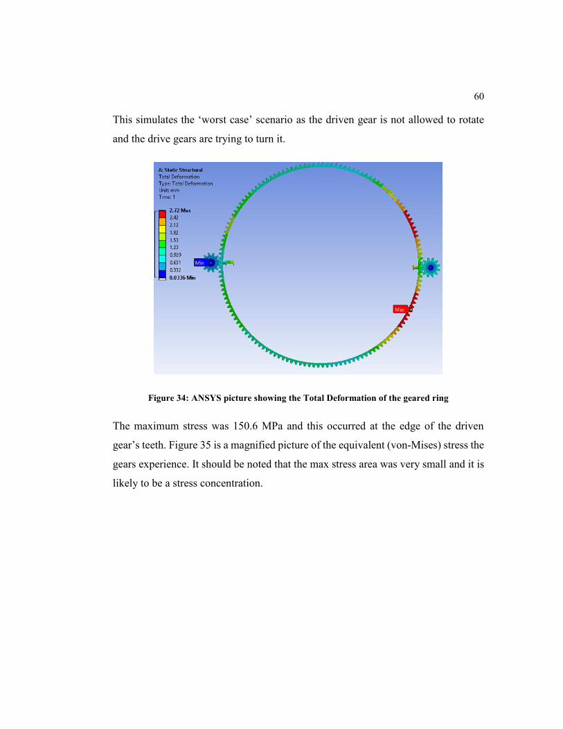
60
This simulates the ‘worst case’ scenario as the driven gear is not allowed to rotate
and the drive gears are trying to turn it.
Figure 34: ANSYS picture showing the Total Deformation of the geared ring
The maximum stress was 150.6 MPa and this occurred at the edge of the driven
gear’s teeth. Figure 35 is a magnified picture of the equivalent (von-Mises) stress the
gears experience. It should be noted that the max stress area was very small and it is
likely to be a stress concentration.

61
Figure 35: ANSYS picture showing the maximum stress on the gear assembly
Figure 36 shows the mesh refinement on this gear assembly and the transition
between bigger nodes to smaller nodes (top of picture to bottom of picture). The
entire assembly was refined but the areas of concern required additional refinement
(smaller nodes). Even though the mesh was refined around the area of concern, an
analysis of the mesh quality indicated that the nodes that covered the drive gear’s
fillet were of a lower quality. Since this is the same area of maximum stress, it is
likely to be a stress concentration.

62
Figure 36: ANSYS picture showing the mesh refinement on the gear assembly
In order to clearly see what happened in the analysis of the gears, a scaled picture of
the total deformation can be seen in Figure 37. In this figure, the deformation is
scaled 63 times that of the original deformation. The driven gear, since it is fixed, is
bending due to the torque applied to the driven gears. The maximum deformation
however is only 2.72mm, which is insignificant and difficult to see on the true scale
picture. The lowest factor of safety experienced was 1.66 at the edge of the drive
gear’s teeth. All of the other areas on this assembly recorded a factor of safety of 5.0
or more. It is also important to note that during normal operation, the gear assembly
will never experience such large forces. The other gears will always be allowed to

63
rotate. The low factor of safety will only be experienced if a component fails causing
one or more of the gears to stop rotating instantly.
Figure 37: ANSYS picture showing a 63x scaled deformation plot of the gear assembly
Force and moment reaction probes were added to the frictionless support of the large
gear. These supports were on either side of the gear and we expected these to have
equal and opposite reaction forces.
Table 9: Table showing the force and moment reactions on the frictionless supports of the big
gear
Gear Force and Moment Reactions (no offset)
Location Reaction x Reaction y Reaction z
Force Reaction Big Gear (N) 0 0 7702.1
Force Reaction Big Gear 2 (N) 0 0 -7795.6
Moment Reaction Big Gear 1 (N.mm) -6.22E+05 -2.23E+07 0
Moment Reaction Big Gear 2 (N.mm) -3.93E+05 2.19E+07 0

64
Discrepancies in the values stemmed from the gear twisting under load. The total
deformation was insignificant (2.72 mm) and the difference in the force values were
also very small (93.5 N).
4.1.4 Final Axis
The final axis rotates the entire system of rings and it is responsible for supporting
the weight of the simulator. The material chosen was standard structural steel as this
is readily available and fairly cheap. To analyze these supports, the weight of the
simulator (excluding these supports and the stand) was calculated using Solidworks.
A force value was then computed from this weight (750kg) using gravity
(9.81𝑚/𝑠2). This simulation is for the worst case, which is when the large gear is
turned on its side. All of the forces due to gravity now act on these supports. Due to
the symmetry of the motion simulator, only one side was analyzed. The force,
approximately 7500N, then had to be divided by 2. A subassembly of these parts was
created and imported into ANSYS. Figure 38 is a total deformation plot from
ANSYS and it shows that these plates deformed at most 0.14mm under full load.
This is an insignificant amount of movement.

65
Figure 38: Ansys picture showing the total deformation of the final axis
It was also important to look at the stress experienced by this part and the safety
factor. The weakest point on this support was again, where it has to be welded. A
factor of safety plot is shown in Figure 39. The highest stress experienced was 55MPa
and the lowest factor of safety was 4.55.

66
Figure 39: Ansys picture showing factor of safety for the final axis
In order to see exactly what happened in the analysis of the final axis, a scaled picture
of the total deformation can be seen in Figure 40. In this figure, the deformation is
scaled 530 times that of the original deformation. All of the forces due to gravity are
acting on the lower plate and it is supported in a bearing by the cylindrical protrusion
(blue in the diagram). In Figure 40, it is now easy to see that the weight of the system
was trying to separate the two supporting plates.
Figure 40: ANSYS picture showing a scaled plot of the total deformation of the final axis

67
4.1.5 Supporting Structure
A basic analysis was done on the supporting structure (stand). This may not
necessarily be used as the motion simulator can be mounted on a translational motion
platform. The stand was made out of Normalized 4130 Chromoly square tubing. The
tube’s cross section measures 2 inches by 2 inches with a 0.25-inch wall thickness.
The weight of the structure was computed and converted to a force value (using
gravity) and applied to the stand. The resulting total deformation is shown in Figure
41. The maximum total deflection was 0.13mm and considered insignificant.
Figure 41: ANSYS picture showing the total deformation of the stand
The stand holds the bearings that allow the entire structure to rotate about the final
axis. Supporting beams were added and triangulated to the block that holds these
bearings. The highest equivalent stress (10.8 MPa) was observed at a lower joint.
This supporting structure was intentionally overdesigned and it can be redesigned to

68
be more efficient. The area of concern and the highest stress value is shown in Figure
42. The highest stress value again occurred at an area that will be welded together.
Figure 42: ANSYS picture showing the area of concern of the stand analysis and the
Equivalent (von- Mises) Stress
4.2 Kinematic Analysis
4.2.1 Mathematical Description of Gimbal Lock
As flight technology advances, spacecrafts and aircrafts become very maneuverable.
Older aircrafts had gravity fed fuel systems that restricted the maneuverability of that
plane significantly. If the plane banks excessively, fuel would be cut off to the engine

69
causing it to stall. Modern aircrafts have fuel pumps and baffled fuel tanks that
remove rotational limitations of the aircraft. Once the plane is structurally capable, it
will have unlimited rotation about its axes. Complicated out of plane maneuvers such
as barrel rolls, lag rolls, displacement rolls and spirals, just to name a few, are part
of aerobatics and military flight training and dates back to the early 1900’s. A three
degree of freedom system will encounter kinematic singularities while trying to
replicate this type of motion. An example of a three degree of freedom gimbal is
shown in Figure 43.
Figure 43: Drawing showing a 3DoF gimbal system
In order to mathematically explain gimbal lock or kinematic singularity, Figure 43
will be referenced. An inertial frame has been set up where the positive y-axis points
up, the positive x-axis points to the right and the positive z-axis points out of the
paper. Each gimbal has its own frame of reference attached to it that rotates with that
gimbal (body fixed reference frame). With the orientation in Figure 43, the outer
gimbal rotates about the x-axis (pitch), the middle gimbal rotates about the y-axis

70
(yaw) and the inner gimbal rotates about the z-axis (roll). In this orientation, the
gimbal frames are all aligned with the inertial frame since this is the starting position.
Rotation about any axis in this system can be converted from the inertial frame using
a transformation matrix. The transformation matrices are given as:
𝑅𝑥(𝜕1) = [
1 0 00 cos(𝛿1) sin(𝛿1)
0 − sin(𝛿1) cos(𝛿1)] (4.1)
𝑅𝑦(𝜕2) = [cos(𝛿2) 0 − sin(𝛿2)
0 1 0𝑠𝑖𝑛(𝛿2) 0 cos(𝛿2)
] (4.2)
𝑅𝑧(𝜕3) = [cos(𝛿3) 𝑠𝑖𝑛(𝛿3) 0
−𝑠𝑖𝑛(𝛿3) cos(𝛿3) 00 0 1
] (4.3)
Where δ in these matrices are rotation angles and the subscripts describe which axis
it is attached to.
The final transformation matrix from the inertial frame to the gimbal frame, used to
convert velocity and acceleration vectors, is the product of the previous three
matrices:
𝑇𝑖𝑛𝑒𝑟𝑡𝑖𝑎𝑙 𝑡𝑜 𝑏𝑜𝑑𝑦 = 𝑅𝑧(𝜕3) ∗ 𝑅𝑦(𝜕2) ∗ 𝑅𝑥(𝜕1) (4.4)
Substituting the transformation matrices 4.1, 4.2 and 4.3:
𝑇𝑖𝑛𝑒𝑟𝑡𝑖𝑎𝑙 𝑡𝑜 𝑏𝑜𝑑𝑦(4.5)
= [
cos(𝛿3) ∗ cos (𝛿2) 𝑠𝑖𝑛(𝛿3) ∗ cos(𝛿1) + cos(𝛿3) ∗ sin(𝛿2) ∗ sin(𝛿1) sin(𝛿3) ∗ sin(𝛿1) − cos(𝛿3) ∗ sin(𝛿2) ∗ cos (𝛿1)
− sin(𝛿3) ∗ cos (𝛿2) cos(𝛿3) ∗ cos(𝛿1) − sin(𝛿3) ∗ sin(𝛿2) ∗ sin (𝛿1) cos(𝛿3) ∗ sin(𝛿1) + sin(𝛿3) ∗ sin(𝛿2) ∗ cos (𝛿1)
sin (𝛿2) − cos(𝛿2) ∗ sin (𝛿1) cos(𝛿2) ∗ cos (𝛿1)
]

71
The transpose of this matrix ([𝑇𝑖𝑛𝑒𝑟𝑡𝑖𝑎𝑙 𝑡𝑜 𝑏𝑜𝑑𝑦]𝑇) can be used to convert kinematic
motions from the body fixed frame to the inertial frame. Euler angles are used to
describe the attitude of the body fixed frame with respect to the inertial frame. The
kinematic motion for the gimbals are determined by computing the inverse of the
mapping matrix from Euler angle rates to body rates (Carter et al. 2014). For the 3-
axis gimbal shown in Figure 43, the Euler angle rates to body rates are given by:
𝜔𝑏𝑜𝑑𝑦𝑏𝑜𝑑𝑦
= 𝑅𝑧(𝜕3) ∗ 𝑅𝑦(𝜕2) ∗ 𝑅𝑥(𝜕1) ∗ [𝜕1̇, 0,0]𝑇
+ 𝑅𝑧(𝜕3) ∗ 𝑅𝑦(𝜕2) ∗ [0, 𝜕2̇, 0]𝑇
+ 𝑅𝑧(𝜕3) ∗ [0,0, 𝜕3̇]𝑇 (4.6)
Substituting equations 4.1, 4.2 and 4.3 into 4.6:
𝜔𝑏𝑜𝑑𝑦𝑏𝑜𝑑𝑦
= [
cos(𝛿2) . cos(𝛿3) sin(𝛿3) 0
− cos(𝛿2) . sin(𝛿3) cos(𝛿3) 0
sin(𝛿2) 0 1
] [
𝛿1̇
𝛿2̇
𝛿3̇
] (4.7)
Where 𝜔𝑏𝑜𝑑𝑦𝑏𝑜𝑑𝑦
is the body angular rate with coordinates in the body fixed reference
frame (Carter et al. 2014). We can then take the inverse of this matrix and use it to
find the required gimbal rates. We will denote the rate vector by �̇� and the matrix by
A:
𝜔𝑏𝑜𝑑𝑦𝑏𝑜𝑑𝑦
= 𝐴 ∗ �̇� (4.8)
The rate vector:
�̇� = 𝐴−1 ∗ 𝜔𝑏𝑜𝑑𝑦𝑏𝑜𝑑𝑦 (4.9)
The inverse of the matrix A (𝐴−1) is given by:
𝐴−1 =1
𝑑𝑒𝑡𝑒𝑟𝑚𝑖𝑛𝑎𝑛𝑡(𝐴)∗ 𝑎𝑑𝑗𝑜𝑖𝑛𝑡(𝐴) (4.10)

72
The determinant of the matrix A is:
𝑑𝑒𝑡𝑒𝑟𝑚𝑖𝑛𝑎𝑛𝑡 (𝐴) = cos(𝛿2) . cos(𝛿3) ∗ cos(𝛿3) − sin(𝛿3) ∗ (− cos(𝛿2) . sin(𝛿3)) (4.11)
𝑑𝑒𝑡𝑒𝑟𝑚𝑖𝑛𝑎𝑛𝑡 (𝐴) = cos(𝛿2) ∗ (cos2 𝛿3 + sin2 𝛿3) = cos (𝛿2) (4.12)
𝑎𝑑𝑗𝑜𝑖𝑛𝑡(𝐴) = [
cos (𝛿3) cos(𝛿2) . sin(𝛿3) −cos(𝛿3) . sin(𝛿2)
− sin(𝛿3) cos(𝛿2) . cos(𝛿3) sin(𝛿3) . sin(𝛿2)
0 0 cos(𝛿2)]
𝑇
(4.13)
𝑎𝑑𝑗𝑜𝑖𝑛𝑡(𝐴) = [
cos(𝛿3) − sin(𝛿3) 0
𝑐𝑜𝑠(𝛿2). sin (𝛿3) 𝑐𝑜𝑠(𝛿2). cos (𝛿3) 0
−𝑐𝑜𝑠(𝛿3). sin (𝛿2) 𝑠𝑖𝑛(𝛿3). sin (𝛿2) cos(𝛿2)] (4.14)
𝐴−1 =1
cos(𝛿2)∗ [
cos(𝛿3) − sin(𝛿3) 0
𝑐𝑜𝑠(𝛿2). sin (𝛿3) 𝑐𝑜𝑠(𝛿2). cos (𝛿3) 0
−𝑐𝑜𝑠(𝛿3). sin (𝛿2) 𝑠𝑖𝑛(𝛿3). sin (𝛿2) cos(𝛿2)] (4.15)
This inverse of A, like any other matrix, only exists if the determinant of A is non-
zero. The determinant of A (stated above) is 𝑐𝑜𝑠(𝛿2). The inverse of A therefore
does not exist where 𝑐𝑜𝑠(𝛿2) is equal to zero. This occurs when 𝛿2 is 𝑛𝜋
2, where 𝑛 =
±1,±3… . At these values of 𝛿2, the system encounters gimbal lock. Referring to
Figure 43, if 𝛿2 is 𝜋
2 or 90 degrees, the red ring rotates 90 degrees about the y-axis
making the rings concentric and the system loses pitching motion.
4.2.2 Four Axis System
A flying machine travelling through space has 6 degrees of freedom, three of which
are rotational. Simulating the attitude of these vehicles can be done with a 3-axis
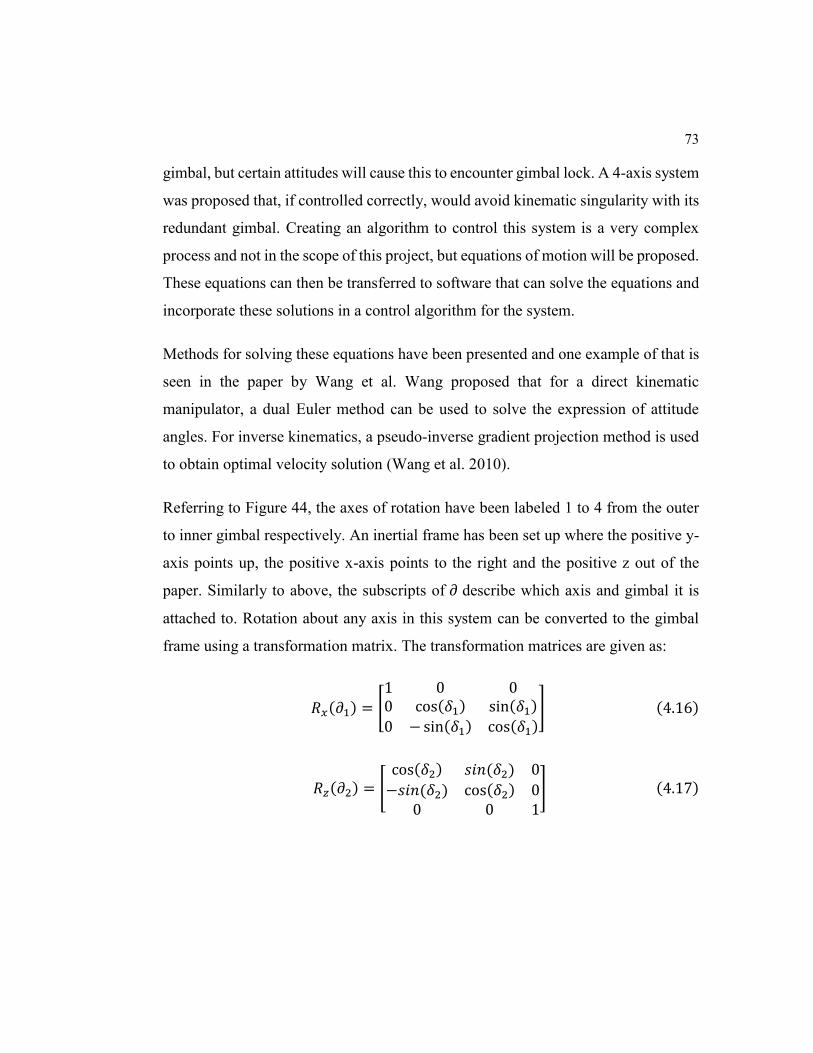
73
gimbal, but certain attitudes will cause this to encounter gimbal lock. A 4-axis system
was proposed that, if controlled correctly, would avoid kinematic singularity with its
redundant gimbal. Creating an algorithm to control this system is a very complex
process and not in the scope of this project, but equations of motion will be proposed.
These equations can then be transferred to software that can solve the equations and
incorporate these solutions in a control algorithm for the system.
Methods for solving these equations have been presented and one example of that is
seen in the paper by Wang et al. Wang proposed that for a direct kinematic
manipulator, a dual Euler method can be used to solve the expression of attitude
angles. For inverse kinematics, a pseudo-inverse gradient projection method is used
to obtain optimal velocity solution (Wang et al. 2010).
Referring to Figure 44, the axes of rotation have been labeled 1 to 4 from the outer
to inner gimbal respectively. An inertial frame has been set up where the positive y-
axis points up, the positive x-axis points to the right and the positive z out of the
paper. Similarly to above, the subscripts of 𝜕 describe which axis and gimbal it is
attached to. Rotation about any axis in this system can be converted to the gimbal
frame using a transformation matrix. The transformation matrices are given as:
𝑅𝑥(𝜕1) = [
1 0 00 cos(𝛿1) sin(𝛿1)
0 − sin(𝛿1) cos(𝛿1)] (4.16)
𝑅𝑧(𝜕2) = [cos(𝛿2) 𝑠𝑖𝑛(𝛿2) 0
−𝑠𝑖𝑛(𝛿2) cos(𝛿2) 00 0 1
] (4.17)
74
𝑅𝑥(𝜕3) = [
1 0 00 cos(𝛿3) sin(𝛿3)
0 − sin(𝛿3) cos(𝛿3)] (4.18)
𝑅𝑦(𝜕4) = [cos(𝛿4) 0 − sin(𝛿4)
0 1 0𝑠𝑖𝑛(𝛿4) 0 cos(𝛿4)
] (4.19)
Figure 44: Drawing of the Full 4-Axis Motion Simulator with Inertial Coordinate System
Like the 3-axis system, a final transformation matrix from the inertial frame to the
gimbal frame can be computed. In this case, the rotation sequence
is: 𝑅𝑦(𝜕4), 𝑅𝑥(𝜕3), 𝑅𝑧(𝜕2), 𝑅𝑥(𝜕1). The complete transformation matrix is given by:
1 (𝜕1)
2(𝜕2) 3 (𝜕3)
4 (𝜕4)

75
𝑇𝑖𝑛𝑒𝑟𝑡𝑖𝑎𝑙 𝑡𝑜 𝑏𝑜𝑑𝑦 = 𝑅𝑦(𝜕4) ∗ 𝑅𝑥(𝜕3) ∗ 𝑅𝑧(𝜕2) ∗ 𝑅𝑥(𝜕1) (4.20)
Using equations 4.16 to 4.19 in equation 4.20:
𝑇𝑖𝑛𝑒𝑟𝑡𝑖𝑎𝑙 𝑡𝑜 𝑏𝑜𝑑𝑦 = (4.21)
[
𝐶𝜕4𝐶𝜕2 − 𝑆𝜕4𝑆𝜕3𝑆𝜕2 𝐶𝜕1 ∗ (𝐶𝜕4𝑆𝜕2 + 𝑆𝜕4𝑆𝜕3𝑆𝜕2) + 𝑆𝜕4𝐶𝜕3𝑆𝜕1 𝑆𝜕1 ∗ (𝐶𝜕4𝑆𝜕2 + 𝑆𝜕4𝑆𝜕3𝐶𝜕2) − 𝑆𝜕4𝐶𝜕3𝐶𝜕1
−𝐶𝜕3𝑆𝜕2 𝐶𝜕3𝐶𝜕2𝐶𝜕1 − 𝑆𝜕3𝑆𝜕1 𝐶𝜕3𝐶𝜕2𝑆𝜕1 + 𝑆𝜕3𝐶𝜕1
𝑆𝜕4𝐶𝜕2 + 𝐶𝜕4𝑆𝜕3𝑆𝜕2 𝐶𝜕1 ∗ (𝑆𝜕4𝑆𝜕2 − 𝐶𝜕4𝑆𝜕3𝐶𝜕2) − 𝐶𝜕4𝐶𝜕3𝑆𝜕1 𝑆𝜕1 ∗ (𝑆𝜕4𝑆𝜕3 − 𝐶𝜕4𝑆𝜕3𝐶𝜕2) + 𝐶𝜕1 ∗ (𝐶𝜕4𝐶𝜕3)]
For the 4-axis gimbal shown in Figure 44, the Euler angle rates to body rates are
given by:
𝜔𝑏𝑜𝑑𝑦𝑏𝑜𝑑𝑦
= 𝑅 𝑦(𝜕4) ∗ 𝑅𝑥(𝜕3) ∗ 𝑅𝑧(𝜕2) ∗ 𝑅𝑥(𝜕1) ∗ [𝜕1̇, 0,0]𝑇
+ 𝑅 𝑦(𝜕4) ∗ 𝑅𝑥(𝜕3) ∗ 𝑅𝑧(𝜕2) ∗ [0,0, 𝜕2̇]𝑇
+ 𝑅 𝑦(𝜕4)
∗ 𝑅𝑥(𝜕3) ∗ [𝜕3̇, 0,0]𝑇 + 𝑅𝑦(𝜕4) ∗ [0, 𝜕4̇ , 0]𝑇 (4.22)
Substituting the transformation matrices (4.16 to 4.19) in equation 4.22:
𝜔𝑏𝑜𝑑𝑦𝑏𝑜𝑑𝑦
= [
𝐶𝜕4𝐶𝜕2 − 𝑆𝜕4𝑆𝜕3𝑆𝜕2 −𝑆𝜕4𝐶𝜕3
−𝐶𝜕3𝑆𝜕2 𝑆𝜕3
𝑆𝜕4𝐶𝜕2 + 𝐶𝜕4𝑆𝜕3𝑆𝜕2 𝐶𝜕4𝐶𝜕3
𝐶𝜕4 00 1
𝑆𝜕4 0]
[ 𝛿1̇
𝛿2̇
𝛿3̇
𝛿4̇]
(4.23)

76
Chapter 5
Conclusion
Modern air and space crafts are capable of large roll, pitch and yaw angles. In some
instances, they can rotate 360 degrees about these axes. Existing aircraft simulators
that feature a motion platform have a limited range of rotational motion. Even some
of the most advanced simulators that exist today can encounter gimbal lock, therefore
making the system incapable of replicating certain maneuvers. The Controlled
Human Gyroscope in this paper had unlimited rotation about all three axes. It used a
redundant gimbal making it a 4-axis system that successfully avoided gimbal lock
unlike the conventional 3-axis setup. Complex maneuvers like those performed by
military and aerobatic pilots can be easily reproduced on this system.
Pilot training in general, and especially for the military, is very expensive because of
the number of flying hours. A high fidelity motion simulator will reduce these hours
therefore reducing the cost of training pilots. The 4-axis human gyroscope proposed
in this paper allows for the simulation of all aircraft maneuvers. Dangerous training
situations can then be presented to the pilots before they actually encounter them in
an aircraft. Some flying situations are too dangerous to actually be practiced such as
spatial disorientation and controlled flight into terrain. These can however be
demonstrated and practiced on a motion simulator. Pilots are not trained in an aircraft
in inclement weather. Introducing pilots to these conditions on a realistic flight
motion simulator can prepare them for such situations as they are sometimes
unavoidable during actual flights.

77
To replicate the rotational motion of a vehicle, each axis of the gyroscope needed to
be independently controlled. Hydraulic motors were used to control the motion of
each axis due to its high torque output and small footprint. The passage of hydraulic
fluid and electricity from the outside of the motion simulator to the internal rings
were one of the challenges faced in the design of this project. Hydraulic rotary unions
with integrated electrical slip rings were selected to overcome this issue. This
allowed the transfer of hydraulic fluid and electricity through freely rotating
components.
The materials selected for the construction of this motion simulator are common,
readily available metals and as a result, they are relatively cheap. These materials
include standard structural steel and Normalized Chromoly 4130. Chromoly is
available in the round tube size that was selected and it can be easily bent into the
desired shape. With the Finite Element Analysis completed in ANSYS, structural
predictions were made on the components of the Human Gyroscope. The situations
where the structure was most likely to fail were replicated and analyzed. The
components on the gyroscope had no less than a 1.6 factor of safety under the most
extreme loading conditions with most factors of safety above 2.9.
The control systems aspect of the Human Gyroscope was not within the scope of this
project, but sufficient information was provided to continue this study. This
information can be used to develop a control algorithm for this system. The
Controlled Human Gyroscope will provide high fidelity motion simulations of air,
space or land vehicles. This system can be added to a translation motion base to
provide up to six degrees of freedom for an even more realistic experience. For
example, the cabin on the NASA AMES vertical motion simulator can be replaced
with the Controlled Human Gyroscope. This will allow for a significant translational

78
and rotational motion envelope. A projector was initially suggested to provide the
visual aspect of the motion simulator. Virtual reality systems are however becoming
very popular and it will provide a more realistic setting. Virtual reality systems are
very small compared to projectors and screens so this will help with packaging
constraints.
Flight motion simulators, according to literature, has to provide high fidelity motion
cues or the simulators can have a negative effect on the users when they transition to
actual aircrafts. The Controlled Human Gyroscope with a suitable control algorithm
will be able to accurately perform these motion cues without the unnecessary
movement of the user since it is able to avoid gimbal lock. A high fidelity simulator
such as this one will provide more accurate research and training capabilities.
5.1 Suggestions for Improvement
While the design of the Controlled Human Gyroscope is complete, improvements
can always be made. Safety of the operator inside the gyroscope and individuals on
the outside is a top priority. A surrounding structure can be built to encase the
gyroscope while leaving enough room for the structure to freely rotate. This will keep
external operators and observers safe.
Idler gears can also be added to the top and bottom of the driven gear to provide
additional support (Figure 45). In the event that the hydraulic systems fail, or if there
is an issue with the control algorithm, these idler gears will keep the driven gear in
place. With the current design, the concentric rings were connected only through the
hydraulic motors and the rotary unions. Forces that are transferred through these
components will add to the frictional losses of the system. In order to minimize
frictional losses, a different support structure can be used with low friction bearings.

79
Figure 45: Picture showing the idler gears that can be added to provide additional safety
The Controlled Human Gyroscope was capable of generating more than a combined
0.2 G’s of acceleration at the operator’s head. If more acceleration is required,
planetary gears can be used between the concentric rings to gain more torque while
staying within the packaging limitations.
80
References
Advani, Sunjoo, Dean Giovannetti, and Michael Blum. 2002. “AIAA 2002-4794
Design of a Hexapod Motion Cueing System for the NASA Ames Vertical
Motion Simulator Background / Introduction,” no. August.
Aeronautics Learning Labrotory. 2004. “Aeronautics- Aircraft Hydraulics- Level 3
(Hydraulic Motors).” http://www.allstar.fiu.edu/aero/hydr19.htm.
Alponso, Bimal L., Duc T. Tran, Jeffery A. Schroeder, and Steven D. Beard. 2009.
“Rotorcraft Research at the NASA Vertical Motion Simulator.” In Atmospheric
Flight Mechanics Conference, 1–17. doi:10.2514/6.2009-6056.
Andrade, Yolanda Nicole. 2013. “An Ergonomic Evaluation of Aircraft Pilot Seats.”
Ansys Inc. 2009. “Structural Analysis Guide” 12.1 (November).
Autunano, Melchor (FAA). 2003. “Spatial Disorientation.” AM-400-03/1.
Biography.com. 2015. “Léon Foucault Biography.” A&E Television Networks.
Accessed November 30. http://www.biography.com/people/léon-foucault-
40760.
Bles, Willem, and Eric Groen. 2009. “The DESDEMONA Motion Facility :
Applications for Space Research,” 281–86. doi:10.1007/s12217-009-9120-1.

81
Boeing Commercial Airplanes. 2010. “Statistical Summary of Commercial Jet
Airplane Accidents.” Boeing Commercial Airplanes, 24.
http://www.boeing.com/commercial/safety/investigate.html.
Burki-Cohen, Judith, and Tiauw H Go. 2005. “The Effect of Simulator Motion Cues
on Initial Training of Airline Pilots.” In AIAA Modeling and Simulation
Technologies Conference and Exhibit, 1–13. doi:10.2514/6.2005-6109.
Burki-cohen, Judith, Tiauw H. Go, and Thomas Longridge. 2001. “FLIGHT
SIMULATOR FIDELITY CONSIDERATIONS FOR TOTAL AIR LINE.” In
AIAA Modeling and Simulation Technologies Conference. doi:10.2514/6.2001-
4425.
Carter, Delano R, Patrick Duffey, Steve Bachorski, and K Martin. 2014. “Weighted
Least-Squares Based Control for a Four Axis Gimbal Set” 7663: 1–12.
doi:10.1117/12.851344.
Chen, Sung Hua, and Li Chen Fu. 2011. “An Optimal Washout Filter Design with
Fuzzy Compensation for a Motion Platform.” IFAC Proceedings Volumes
(IFAC-PapersOnline) 18 (PART 1): 8433–38. doi:10.3182/20110828-6-IT-
1002.03176.
Chung, William W Y, and Walter W Johnson. 1997. “VISUAL SPATIAL-
FREQUENCY ON SIMULATION CUEING,” 509–23. doi:10.2514/6.1997-
3655.
Clement, Gilles, and Angie Bukley. 1989. Artificial Gravity. Edited by James R.
Wertz. Journal of Chemical Information and Modeling. Vol. 53. Microcosm
Press and Springer. doi:10.1017/CBO9781107415324.004.

82
Department of Defence. 2015. “Estimated Impacts of Sequestration-Level Funding
FISCAL YEAR 2015 BUDGET REQUEST.”
Department of the Air Force. 2014. “Fiscal Year (FY) 2015 Budget Estimates.”
United States Air Force.
Duncan, Jeff. 2007. “Fidelity Versus Cost.” Old Dominion University.
Dynamic Sealing Technologies INC. 2008. Rotary Union Solutions.
Erwin, Sandra I. 2012. “Budget Cuts, Fuels Costs Could Spur Military Spending on
Virtual Training.” National Defense Industrial Association, December.
http://www.nationaldefensemagazine.org/archive/2012/December/Pages/Budg
etCuts,FuelsCostsCouldSpurMilitarySpendingonVirtualTraining.aspx.
Fabricast INC. 2016. “Slip Ring Mounting Methods.”
http://www.fabricast.com/fabricast-products/stock-slip-ring-assemblies/slip-
ring-mounting-methods/.
Federal Aviation Administration. 1991. “Airplane Simulator Qualification.” U.S.
Department of Transportation.
———. 2010. “Weather-Related Aviation Accident Study 2003-2007.”
GBC. 2014. “Going Virtual To Prepare for a New Era of Defense How Virtual
Training Can Help the.”
Gonzalez, Carlos. 2015. “What’s the Difference Between Bearings?” Machine
Design. http://machinedesign.com/whats-difference-between/what-s-
difference-between-bearings-1.

83
Goossens, R. H M, C. J. Snijders, and T. Fransen. 2000. “Biomechanical Analysis of
the Dimensions of Pilot Seats in Civil Aircraft.” Applied Ergonomics 31 (1): 9–
14. doi:10.1016/S0003-6870(99)00028-9.
Greenwood, Donald T. 1988. Principles of Dynamics. 2nd ed. Prentice Hall, Inc.
Hahn, Donald L. 2013. “When Electric Motors Won’t Do.” Lamina Hydraulics.
http://machinedesign.com/motorsdrives/when-electric-motors-won-t-do.
Hamrock, B J, and W J Anderson. 1980. “Rolling-Element Bearings.” Stress The
International Journal on the Biology of Stress, no. June: 283–310.
doi:10.1016/0301-679X(78)90097-X.
Jie, M A, and X U Qinbei. 2015. “Four-Axis Gimbal System Application Based on
Gimbal Self-Adaptation Adjustment” 3: 8866–71.
Kjellin, Alexander, and Mattias Runevad. 2012. “The Human Gyroscope,” no.
December.
Longridge, Thomas, Judith Burki-Cohen, Tiauw H. Go, and Andrew J. Kendra.
2001. “SIMULATOR FIDELITY CONSIDERATIONS FOR TRAINING
AND EVALUATION OF.” In 11th International Symposium on Aviation
Psychology, 5–8.
Mario N. Armenise, Caterina Ciminelli, Francesco Dell’Olio, Vittorio M. N. Passaro.
2013. Advanced in Gyroscope Technologies. Journal of Chemical Information
and Modeling. Vol. 53. doi:10.1017/CBO9781107415324.004.

84
Marsh, Alton K. 2011. “ABC’s of Flight Simulators.” Aircraft Owners and Pilots
Association. http://www.aopa.org/News-and-Video/All-
News/2011/May/1/ABCs-of-Simulators.
Nooij, Suzanne A E, and Eric L. Groen. 2011. “Rolling into Spatial Disorientation:
Simulator Demonstration of the Post-Roll (Gillingham) Illusion.” Aviation
Space and Environmental Medicine 82 (5): 505–12.
doi:10.3357/ASEM.2946.2011.
Page, Rl. 2000. “Brief History of Flight Simulation.” In SimTecT 2000 Proceedings,
1–11. doi:10.1.1.132.5428.
Philippus Feenstra, Mark Wentink, Bruno Correia Gracio, and Wim Bles. 2009.
“EFFECT OF SIMULATOR MOTION SPACE ON REALISM IN THE
DESDEMONA SIMULATOR.”
Rogers, Rodney O., Albert Boquet, Cass Howell, and Charles DeJohn. 2007.
“Preliminary Results of an Experiment to Evaluate Transfer of Low-Cost ,
Simulator-Based Airplane Upset-Recovery Training.” Aerospace, no. October.
Roza, Manfred, Mark Wentink, and Philippus Feenstra. 2007. “Performance Testing
of the Desdemona Motion System,” no. August: 1–14.
Strachan, Ian W. 2000. “Technology Leaps All Around Propel Advances in
Simulators.” NDIA’s Business and Technology Magazine, November.
http://www.nationaldefensemagazine.org/archive/2000/November/Pages/Tech
nology_Leaps7194.aspx.

85
Stroud, Kenneth J., Deborah L. Harm, and David M. Klaus. 2003. “Using Virtual
Reality for Predicting and Preventing Space Motion Sickness.” 54th
International Astronautical Congress of the International Astronautical
Federation, the International Academy of Astronautics, and the International
Institute of Space Law, no. October. doi:10.2514/6.IAC-03-G.2.02.
Terdiman, Daniel. 2009. “A Wild Ride on NASA’s Massive Flight Simulator.”
CNET. http://www.nasa.gov/vision/earth/improvingflight/vms.html.
Van Silfhout, Roelof G. 2001. “High-Precision Hydraulic Stewart Platform” 70 (8):
3488–95.
Wang, Xiaochen, Hui Zhao, Kemao Ma, Xin Huo, and Yu Yao. 2010. “Kinematics
Analysis of a Novel All-Attitude Flight Simulator” 53 (2): 236–47.
doi:10.1007/s11432-010-0042-8.
Wentink, Mark, Wim Bles, Ruud Hosman, Michael Mayrhofer, Technical Manager,
and Desdemona Program. 2005. “Design & Evaluation of Spherical Washout
Algorithm for Desdemona Simulator,” no. August.
Woodcock, Christian. 2013. “Frame Materials and What to Buy.”
http://www.bikeroar.com/tips/frame-materials-and-what-to-buy.