Title: On the use of steel pipe for crossing fault of ...
13
Cover page Title: On the use of steel pipe for crossing fault of flexure type in the Tama South-North line (tentative) development project Authors: Takeo Kitamura (Contact person, Presenter) Director for Engineering Section of Asaka Purification Administration Office Bureau of Waterworks, Tokyo Metropolitan Government 1-3-1 Miyato, Asaka City, Saitama, Japan, 351-0031 TEL (81)-48-475-3215 FAX (81)-48-472-8703 E-mail: [email protected]
Transcript of Title: On the use of steel pipe for crossing fault of ...

Cover page
Title: On the use of steel pipe for crossing fault of flexure type in the Tama South-North line (tentative)
development project
Authors: Takeo Kitamura (Contact person, Presenter)
Director for Engineering Section of Asaka Purification Administration Office
Bureau of Waterworks, Tokyo Metropolitan Government
1-3-1 Miyato, Asaka City, Saitama, Japan, 351-0031
TEL (81)-48-475-3215
FAX (81)-48-472-8703
E-mail: [email protected]
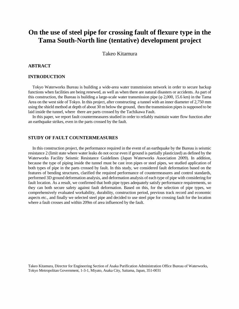
On the use of steel pipe for crossing fault of flexure type in the
Tama South-North line (tentative) development project
Takeo Kitamura
ABTRACT
INTRODUCTION
Tokyo Waterworks Bureau is building a wide-area water transmission network in order to secure backup
functions when facilities are being renewed, as well as when there are natural disasters or accidents. As part of
this construction, the Bureau is building a large-scale water transmission pipe (φ 2,000, 15.6 km) in the Tama
Area on the west side of Tokyo. In this project, after constructing a tunnel with an inner diameter of 2,750 mm
using the shield method at depth of about 30 m below the ground, then the transmission pipes is supposed to be
laid inside the tunnel, where there are parts crossed by the Tachikawa Fault.
In this paper, we report fault countermeasures studied in order to reliably maintain water flow function after
an earthquake strikes, even in the parts crossed by the fault.
STUDY OF FAULT COUNTERMEASURES
In this construction project, the performance required in the event of an earthquake by the Bureau is seismic
resistance 2 (limit state where water leaks do not occur even if ground is partially plasticized) as defined by the
Waterworks Facility Seismic Resistance Guidelines (Japan Waterworks Association 2009). In addition,
because the type of piping inside the tunnel must be cast iron pipes or steel pipes, we studied application of
both types of pipe in the parts crossed by fault. In this study, we considered fault deformation based on the
features of bending structures, clarified the required performance of countermeasures and control standards,
performed 3D ground deformation analysis, and deformation analysis of each type of pipe with considering for
fault location. As a result, we confirmed that both pipe types adequately satisfy performance requirements, so
they can both secure safety against fault deformation. Based on this, for the selection of pipe types, we
comprehensively evaluated workability, durability, construction period, previous track record and economic
aspects etc., and finally we selected steel pipe and decided to use steel pipe for crossing fault for the location
where a fault crosses and within 209m of area influenced by the fault.
Takeo Kitamura, Director for Engineering Section of Asaka Purification Administration Office Bureau of Waterworks,
Tokyo Metropolitan Government, 1-3-1, Miyato, Asaka City, Saitama, Japan, 351-0031

1. INTRODUCTION
Bureau of Waterworks, Tokyo Metropolitan Government is building a wide-area water transmission network
in order to secure backup functions when facilities are being renewed, as well as when there are natural
disasters or accidents. As part of this construction, the Bureau is building the Tama South-North Trunk Line
(tentative name) on the west side of Tokyo. This water transmission trunk line involves using the shield
construction technique to build a tunnel with an inner diameter of 2,750 mm at a depth. Of 30 m below the
ground, stretching 15.6 km from Higashimurayama Water Purification Plant to Haijima Water Supply Station,
then building a φ2000 large water transmission pipe inside the tunnel. This construction will make it possible to
renovate and install seismic resistant joints on other water transmission pipes, and improve the stability of
water supply to approximately 1.7 million people living in the western and southern parts of the Tama Area.
The active Tachikawa Fault runs through this construction area, so the Bureau has studied countermeasures to
absorb fault displacement. In this paper, we report on a study case for the water transmission trunk line to be
built in the section that the fault runs through.
Figure 1: Major water supply facilities of the Tokyo Metropolitan Bureau of Waterworks
2. DETAILDS OF THE TACHIKAWA FAULT
The Tachikawa fault is a reverse active fault with its upper
block on the east side. In the future, there is a 0.5% to 2%
chance of an earthquake happening in the next 30 years, which
places it in the group of faults with a relatively high chance of
an earthquake happening among faults in Japan. Vertical
sliding during fault activity is estimated to be 1.5 to 3.0. m.
Despite the fact that it is a reverse fault, even if the fault slides
very deep underground, it has a structure called flexure that
will make the fault slide barely appear above ground. Known
details of the Tachikawa Fault are shown in TABLE 1.
Figure 2: Image of a flexure structure (reverse fault)
Flexure Cliff
Fault
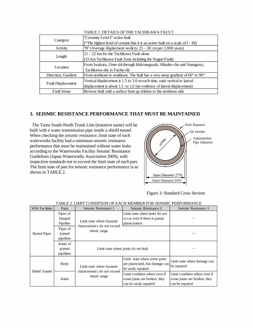
TABLE 1. DETAILS OF THE TACHIKAWA FAULT
Category"Certainty Level I" active fault
(*The highest level of certaint that it is an active fault on a scale of I - III)
Activity "B" (Average displacment veolicty: 25 - 30 cm per 1,000 years)
Length21 - 22 km for the Tachikawa Fault alone
(33 km Tachikawa Fault Zone including the Naguri Fault)
Fault Sense Reverse fault with a surface bent up relative to the northeast side
LocationFrom Iwakura, Ome-shi through Hakonegasaki, Mizuho-cho and Sunagawa,
Tachikawa-shi, to Fuchu-shi
Direction, Gradient From northeast to southeast. The fault has a very steep gradient of 60° to 90°.
Fault DisplacementVertical displacement is 1.5 to 3.0 m each time, ratio vertical to lateral
displacement is about 1:1. to 1:2 (no evidence of lateral displacement)
3. SEISMIC RESISTANCE PERFORMANCE THAT MUST BE MAINTAINED
The Tama South-North Trunk Line (tentative name) will be
built with a water transmission pipe inside a shield tunnel.
When checking the seismic resistance, limit state of each
waterworks facility had a minimum seismic resistance
performance that must be maintained without water leaks
according to the Waterworks Facility Seismic Resistance
Guidelines (Japan Waterworks Association 2009), with
inspection standards not to exceed the limit state of each part.
The limit state of part for seismic resistance performance is as
shown in TABLE 2.
Figure 3: Standard Cross Section
TABLE 2. LIMIT CONDITION OF EACH MEMBER FOR SEISMIC PERFORMANCE
WW Facilities
Shield Tunnel
BodyLimit state where dynamic
characteristics do not exceed
elastic range
Limit state where some parts
are plasticized, but damage can
be easily repaired
Limit state where damage can
be repaired
Joints
Limit condition where even if
some joints are broken, they
can be easily repaired
Limit condition where even if
some joints are broken, they
can be repaired
Parts Seismic Resistance 1 Seismic Resistance 2 Seismic Resistance 3
Buried Pipes
Pipes of
Integral
PipelineLimit state where dynamic
characteristics do not exceed
elastic range
Limit state where leaks do not
occur even if there is partial
plasticization
~
Pipes of
jointed
pipelines
~
Joints of
jointed
pipelines
Limit state where joints do not leak ~
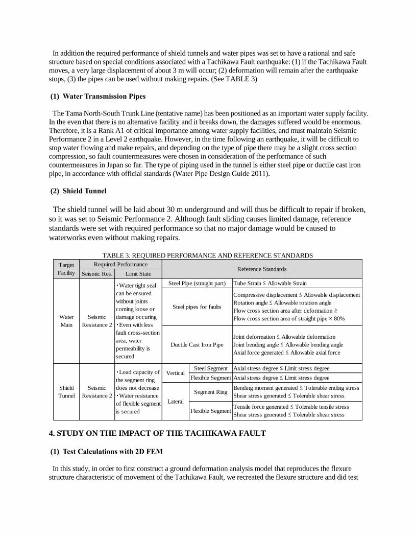
In addition the required performance of shield tunnels and water pipes was set to have a rational and safe
structure based on special conditions associated with a Tachikawa Fault earthquake: (1) if the Tachikawa Fault
moves, a very large displacement of about 3 m will occur; (2) deformation will remain after the earthquake
stops, (3) the pipes can be used without making repairs. (See TABLE 3)
(1) Water Transmission Pipes
The Tama North-South Trunk Line (tentative name) has been positioned as an important water supply facility.
In the even that there is no alternative facility and it breaks down, the damages suffered would be enormous.
Therefore, it is a Rank A1 of critical importance among water supply facilities, and must maintain Seismic
Performance 2 in a Level 2 earthquake. However, in the time following an earthquake, it will be difficult to
stop water flowing and make repairs, and depending on the type of pipe there may be a slight cross section
compression, so fault countermeasures were chosen in consideration of the performance of such
countermeasures in Japan so far. The type of piping used in the tunnel is either steel pipe or ductile cast iron
pipe, in accordance with official standards (Water Pipe Design Guide 2011).
(2) Shield Tunnel
The shield tunnel will be laid about 30 m underground and will thus be difficult to repair if broken,
so it was set to Seismic Performance 2. Although fault sliding causes limited damage, reference
standards were set with required performance so that no major damage would be caused to
waterworks even without making repairs.
TABLE 3. REQUIRED PERFORMANCE AND REFERENCE STANDARDS
Steel Segment
Flexible Segment
Target
Facility
Required PerformanceReference Standards
Seismic Res. Limit State
Water
Main
Seismic
Resistance 2
・Water tight seal
can be ensured
without joints
coming loose or
damage occuring
・Even with less
fault cross-section
area, water
permeability is
secured
Steel Pipe (straight part) Tube Strain ≤ Allowable Strain
Steel pipes for faults
Compressive displacement ≤ Allowable displacement
Rotation angle ≤ Allowable rotation angle
Flow cross section area after deformation ≥
Flow cross section area of straight pipe × 80%
Ductile Cast Iron Pipe
Joint deformation ≤ Allowable deformation
Joint bending angle ≤ Allowable bending angle
Axial force generated ≤ Allowable axial force
Shield
Tunnel
Seismic
Resistance 2
・Load capacity of
the segment ring
does not decrease
・Water resistance
of flexible segment
is secured
VerticalAxial stress degree ≤ Limit stress degree
Axial stress degree ≤ Limit stress degree
Lateral
Segment RingBending moment generated ≤ Tolerable ending stress
Shear stress generated ≤ Tolerable shear stress
Flexible SegmentTensile force generated ≤ Tolerable tensile stress
Shear stress generated ≤ Tolerable shear stress
4. STUDY ON THE IMPACT OF THE TACHIKAWA FAULT
(1) Test Calculations with 2D FEM
In this study, in order to first construct a ground deformation analysis model that reproduces the flexure
structure characteristic of movement of the Tachikawa Fault, we recreated the flexure structure and did test

calculations of fault deformation using a 2D FEM model assuming stratified ground. We also confirmed the
applicability of shield tunnels and water transmission pipes as fault countermeasure construction methods with
the response displacement method using the fault displacement calculated. A) Simulation Analysis of the Present Conditions of the Ground
After applying dead weight to the
FEM model of the ground without the
tunnel and simulating the initial stress
rate, we forcibly input the sliding caused
by fault activity (fault angle 60°, vertical
sliding 5 m, no lateral sliding) reported
to have occurred in the past on the lower
surface of the model. This confirmed the
flexure structure of the ground surface
in its present condition, in which the flex
width is approximately 200 m when
sliding vertically 5 m on the ground
surface.
Figure 4: Range in which to analyze ground deformation
B) Fault Effect Analysis on the Ground Surface
Based on the existing material on the Tachikawa Fault and interviews with experts, we set CASE 1 assuming
a reverse fault with the upper block on the east side and CASE 2 assuming a left lateral fault (See TABLE 4),
then calculated fault displacement with 2D FEM.
TABLE 4. IMPACT ANALYSIS CASES
Case Fault Angle Vertical Displ. Lateral Displ. Comp. Displ.
CASE1
(Reverse Fault)60° 3.0 m (Max) - 3.0 m
CASE2
(Vert. & Lat. Fault)80° 1.5 m
3.0 m
(Max 1: 2)3.4 m
At the tunnel position, there was vertical displacement of about 3 m in CASE 1 and 1.5 m in CASE 2, as well
as pipe axial displacement of about 1.5 m in CASE 1 and about 2 m in CASE 2. Converting vertical
displacement into angle, this equates to 0.9° in CASE 1 and 0.4° in CASE 2, with the result being that impact
on the water transmission pipe is minimal.
However, in the study of fault countermeasures, because CASE 2 has a large pipe axial displacement, which
will have a greater impact on the compression strain of the water pipe, we decided to use the fault displacement
of CASE 2.
Boring spot (already surveyed)
Boring spot (to be surveyed)
Legend
Deformation and slope direction of spot
Tachikawa fault
Planned Line

C) Study of Vertical Displacement of the Shield Tunnel and Water Transmission Pipe
There are two methods for examining the seismic resistance of shield tunnels and water pipes. The first
method is to do FEM analysis of an integrated model of the ground and tunnel. The second is to do response
displacement analysis of the tunnel and water transmission pipe models.
In this sort of situation, when considering seismic countermeasures for shield tunnels across faults, it is
impossible to prevent major sliding displacement of the Tachikawa Fault, so it is more effective to absorb
displacement with flexible joints using flexible segments or the like.
It is difficult to model flexible segments based on major deformation such as fault displacement or do
modeling that incorporates shield tunnels and water transmission pipes that behave as one with those segments
using FEM elements, so we modeled the tunnel and water pipes with beam elements and did analysis with the
response displacement method using displacement due to fault sliding as an external force.
The results, as shown in TABLE 5, confirmed that both steel pipes and ductile cast iron pipes were effective
as countermeasures against ground deformation when the Tachikawa Fault is active.
TABLE 5. SUMMARY OF TEST CALSULATIONS
Water MainFlexible
Segment
Steel pipes
for faults:
9 places
Compression
Performance
of 150 mm:
29 places
None
(1) Steel pipes for faults
・Compression displacement:
205 mm ≤ 368 mm PASS
・Rotation Angle: 0.10°≤ 12° PASS
(2) Straight Pipe
・Strain: 0.2% ≤ 0.35% PASS
・ Both the steel pipes for faults and straight
pipes satisfy seismic safety requirements.
・ Because there is no filler, there is a strong
possibility that the water main and the tunnel will
move separately and the two will come in contact.
Steel pipes
for faults:
9 places
Compression
Performance
of 150 mm:
29 places
Air milk with
compression
strength of
0.5N/mm2
(1) Steel pipes for faults
・Compression displacement:
443 mm ≤ 368 mm FAIL
・Rotation Angle: 0.33°≤ 12° PASS
(2) Straight Pipe
・Strain: 0.12% ≤ 0.35% PASS
・ Although the steel pipes for faults do not
satisfy safety requirements at present, it is
necessary to examin the potential to increase the
allowable compression displacement to 450 mm
or more by changing the specifications of the
steel pipes for faults (Solved issue later through
development).
・ Air milk filling makes the water main and
tunnel behave as one, there is no problem ith
them contacting each other.
Ductile Cast
Iron Pipe
Fault
Section:
3 m pipe
(200 m)
Outside Fault
Section:
5 m pipe
Compression
Performance
of 150 mm:
29 places
Air milk with
compression
strength of
0.5N/mm2
(1) Joint
・Compression Force:
2252 kN ≤ 5880 kN PASS
・Verification of overall
expansion/contraction:
Fault displacement
2 m ≤ 2.03 m (= 29 mm × 70 pipes)
・Rotation Angle:0.35°≤ 1.83° PASS
(2) Straight Pipe
・Stress: 16 N/mm2 ≤ 270 N/mm2 PASS
・Ductile cast iron pipes satisfy seismic safety
requirements.
・ Air milk filling makes the ductile pipe and
tunnel behave as one, there is no problem ith
them contacting each other.
Comment
Steel Pipe
Type of Pipe
Fault Countermeasures
Filler Results of trial calculations
(2) 3D Ground Deformation Analysis Simulation
Based on the results of 2D FEM analysis and ground survey results conducted separately, we constructed a
3D FEM model by modeling the strata structure in the area where the pipeline crosses the Tachikawa Fault, and
analyzed ground deformation when the fault is active with either vertical sliding or lateral sliding.
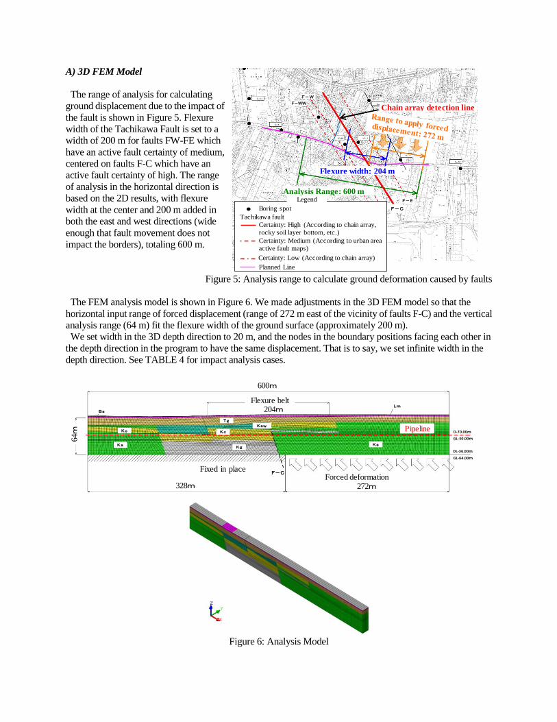
A) 3D FEM Model
The range of analysis for calculating
ground displacement due to the impact of
the fault is shown in Figure 5. Flexure
width of the Tachikawa Fault is set to a
width of 200 m for faults FW-FE which
have an active fault certainty of medium,
centered on faults F-C which have an
active fault certainty of high. The range
of analysis in the horizontal direction is
based on the 2D results, with flexure
width at the center and 200 m added in
both the east and west directions (wide
enough that fault movement does not
impact the borders), totaling 600 m.
Figure 5: Analysis range to calculate ground deformation caused by faults
The FEM analysis model is shown in Figure 6. We made adjustments in the 3D FEM model so that the
horizontal input range of forced displacement (range of 272 m east of the vicinity of faults F-C) and the vertical
analysis range (64 m) fit the flexure width of the ground surface (approximately 200 m).
We set width in the 3D depth direction to 20 m, and the nodes in the boundary positions facing each other in
the depth direction in the program to have the same displacement. That is to say, we set infinite width in the
depth direction. See TABLE 4 for impact analysis cases.
Figure 6: Analysis Model
328m 272m
強制変位固定
F-C
204m
600m
撓曲帯
64m
D-70.00m
DL-36.00m
Kc Kc
Ks KsKg
Tg
Bs
Lm
Ksw
GL-30.00m
GL-64.00m
トンネル位置
Flexure belt
Fixed in placeForced deformation
Pipeline
328m 272m
204m
600m
64m
凡 例
ボーリング調査地点
Flexure width: 204 m
Analysis Range: 600 m
確実度 高(チェーンアレイ、礫層基底面等)
確実度 中(都市圏活断層図による)
確実度 低(チェーンアレイ)
計画路線
立川断層
F-WW
F-C
F-W
F-E
Boring spot
Tachikawa fault
Legend
Certainty: High (According to chain array,
rocky soil layer bottom, etc.)
Certainty: Medium (According to urban area
active fault maps)
Planned Line
Certainty: Low (According to chain array)
Chain array detection line
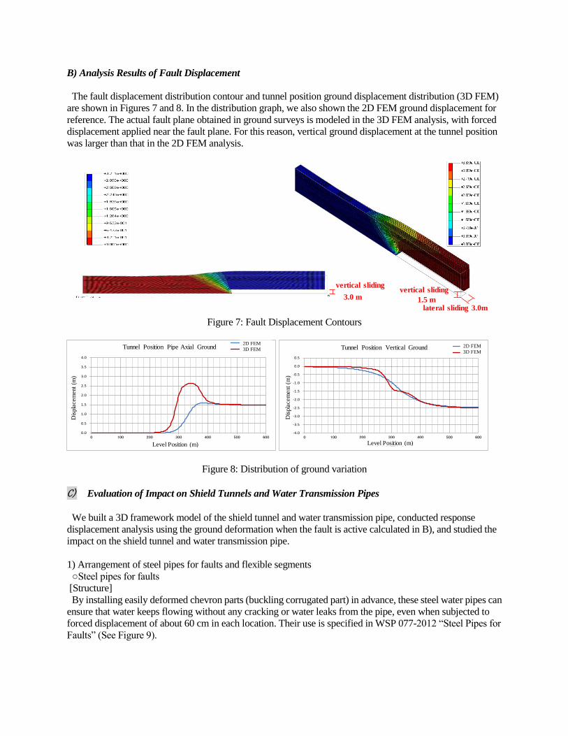
B) Analysis Results of Fault Displacement
The fault displacement distribution contour and tunnel position ground displacement distribution (3D FEM)
are shown in Figures 7 and 8. In the distribution graph, we also shown the 2D FEM ground displacement for
reference. The actual fault plane obtained in ground surveys is modeled in the 3D FEM analysis, with forced
displacement applied near the fault plane. For this reason, vertical ground displacement at the tunnel position
was larger than that in the 2D FEM analysis.
Figure 7: Fault Displacement Contours
Figure 8: Distribution of ground variation
C) Evaluation of Impact on Shield Tunnels and Water Transmission Pipes
We built a 3D framework model of the shield tunnel and water transmission pipe, conducted response
displacement analysis using the ground deformation when the fault is active calculated in B), and studied the
impact on the shield tunnel and water transmission pipe.
1) Arrangement of steel pipes for faults and flexible segments
○Steel pipes for faults
[Structure] By installing easily deformed chevron parts (buckling corrugated part) in advance, these steel water pipes can
ensure that water keeps flowing without any cracking or water leaks from the pipe, even when subjected to
forced displacement of about 60 cm in each location. Their use is specified in WSP 077-2012 “Steel Pipes for
Faults” (See Figure 9).
vertical sliding
3.0 m
lateral sliding 3.0m
vertical sliding
1.5 m
0.0
0.5
1.0
1.5
2.0
2.5
3.0
3.5
4.0
0 100 200 300 400 500 600
変位(m
)
水平位置(m)
トンネル位置の鉛直方向地盤変位2次元FEM
3次元FEM
-4.0
-3.5
-3.0
-2.5
-2.0
-1.5
-1.0
-0.5
0.0
0.5
0 100 200 300 400 500 600
変位(m
)
水平位置(m)
トンネル位置の管軸方向地盤変位 2次元FEM
3次元FEM
-4.0
-3.5
-3.0
-2.5
-2.0
-1.5
-1.0
-0.5
0.0
0.5
0 100 200 300 400 500 600
変位(m
)
水平位置(m)
トンネル位置の管軸直角方向地盤変位 2次元FEM
3次元FEM
Tunnel Position Pipe Axial Ground
Level Position (m)
Dis
pla
cem
ent
(m)
2D FEM
3D FEM
0.0
0.5
1.0
1.5
2.0
2.5
3.0
3.5
4.0
0 100 200 300 400 500 600
変位(m
)
水平位置(m)
トンネル位置の鉛直方向地盤変位2次元FEM
3次元FEM
-4.0
-3.5
-3.0
-2.5
-2.0
-1.5
-1.0
-0.5
0.0
0.5
0 100 200 300 400 500 600
変位(m
)
水平位置(m)
トンネル位置の管軸方向地盤変位 2次元FEM
3次元FEM
-4.0
-3.5
-3.0
-2.5
-2.0
-1.5
-1.0
-0.5
0.0
0.5
0 100 200 300 400 500 600
変位(m
)
水平位置(m)
トンネル位置の管軸直角方向地盤変位 2次元FEM
3次元FEM
Tunnel Position Vertical Ground
Level Position (m)
Dis
pla
cem
ent
(m)
2D FEM
3D FEM

Figure 9: Steel pipes for faults
[Mechanism of fault displacement absorption]
By absorbing deformation, the easily deformed chevron parts (buckling corrugated part) follows the large
fault displacement (See Figure 10).
Figure 10: Fault displacement mechanism
[Arrangement]
In consideration of the ground strain in CASE 1 and CASE 2, we set the shared strain of each corrugated part
was based on the allowable compression displacement of the steel pipe for faults, and determined the
arrangement of the steel pipes for faults and flexible segments (Figure 11).
Figure 11: Arrangement of steel pipes for faults
Sleeve pipe Sleeve pipe
Corrugated pipe
Steel pipe for faults
Corrugated pipe
Normally
In an earthquake
Fault plane
Fault plane
Fault movement
0.000
0.005
0.010
0.015
0.020
0.025
0.030
0.035
200 250 300 350 400
トンネル軸方向の地盤の軸ひずみ
座標(m)
断層F-C位置 断層鋼管位置 縦ずれ型 縦横ずれ型 分担ひずみ (1箇所の可とうセグメントが分担するひずみを示す。)Fault F-C
position
Fault steel pipe
position
Vertical
Sliding
Vertical and
lateral sliding
Shared strain
(indicates strain shared by one flexible segment)
Tun
nel
radia
l dir
ectio
n st
rain
Coordinates (m)

2) Arrangement ductile cast iron pipes and flexible segments
○US ductile cast iron pipes
[Structure] These cast-iron pipes (see Figure 12) have seismic resistant joints that can expand and contract, are flexible,
and have a detachment prevention function. By installing long joint rings, it is possible to increase the
allowable expansion and contraction of the pipeline. (See Figure 13).
It is possible to build an optimal seismic resistant
pipeline according to the degree of ground
displacement (major displacement response pipeline
system) by combining existing products, such as by
shortening the pipeline in this section according to the
degree of ground displacement, and arranging long
joint rings on both sides of the section.
Figure 12: US Ductile Cast Iron Pipe
[Mechanism of fault displacement absorption]
Even if deformation occurs in one joint, adjacent joints move one after another and long joint rings absorb
major deformation, following large fault displacements. Even if tension, compression, and bending
displacement occur, the joints also move so stress on the pipeline is alleviated.
Figure 13: Major displacement pipeline system with long joint ring units
[Arrangement]
In order to cope with fault displacement in CASE 1 and CASE 2, we applied a major displacement pipeline
system that combines long joint ring units and short pipes to the ductile cast iron pipes, and arranged piping to
absorb ground displacement. We also determined the arrangement of flexible segments so that they follow
fault displacement (See Figure 14).
US Ductile
Cast Iron Pipe
:Long Joint Ring Unit :US ductile iron pipes (L = 1.8 m)
Shield
Segment
:Steel Segment :Flexible Segment 100 mm type :Flexible Segment 300 mm type
(6 places) (7 places)
Figure 14: Arrangement of US ductile cast iron pipes and shield segments
直管 1.8m×17本+長尺継ぎ輪ユニット
長尺継ぎ輪ユニット(5.4m)
36m
直管(1.8m)Long joint ring unit
(5.4 m)Straight pipe 1.8 m
Straight pipe 1.8 m × 17 pipes
+ Long joint ring unit36m
36 36 36 36 36
Lock ring rubber
Split ring
Push ringFilling mortar
Socket
Lock ring Rubber ring Bolt / Joint RodPlug
Highly compressible in pipe axial direction

3) Analysis results of ground deformation in the flexure structure
As shown in TABLE 6, we confirmed that in CASE 1 (reverse fault) and CASE 2 (vertical and lateral sliding
fault), both the steel pipes for faults (13 places) and ductile cast iron pipes (major displacement response
pipeline system using long joint units) were within the reference standards for each item, and serve as effective
countermeasures against the impact of the Tachikawa Fault.
TABLE 6. ANALYSIS RESULTS FOR GROUNND DISPLACEMENT IN THE FLEXURE STRUCTURE
Comp.
DisplacementPASS
Bending Angle PASS
Strain PASS
Steel Segment PASS
PASS
PASS
PASS
Steel Segment PASS
Comp.
DisplacementPASS
Bending Angle PASS
Strain PASS
Steel Segment PASS
PASS
PASS
PASS
Steel Segment PASS
Shield TunnelFlexible Segments: 13
placesVertical
Stress: 140 N/mm2 ≤ 490 N/mm
2
Flexible
Segment
Using a product within the cross-section generated, the segment
does not breakPASS
PASS
Water Main
Ductile cast iron pipes
using long joint unit
(major displacement pipe
system)
Joint
Deformation79 mm ≤ 310 mm
Joint Bending
Angle1.52° ≤ 5.9°
Axial Force
Generated5852 kN ≤ 6000 kN
Shield TunnelFlexible Segments: 13
placesVertical
Stress: 120 N/mm2 ≤ 490 N/mm
2
Flexible
Segment
Using a product within the cross-section generated,the segment
does not breakPASS
CASE 2
Vertical &
Lateral Fault
CASE 2
Water Main
Fault Countermeasure
Steel pipes for faults:
13 places
Waveform
Part
300 mm ≤ 320 mm
0.84° ≤ 16°
Flow
Cross-Section
The bending angle is small and does not affect.
The water flow (secured 80% or more)PASS
Straight Part 0.12% ≤ 0.34%
Shield TunnelFlexible Segments: 13
placesVertical
Stress: 345 N/mm2 ≤ 490 N/mm
2
Flexible
Segment
Using a product within the cross-section generated, the segment
does not break
CASE 1
Reverse
Fault
Water Main
Water Main
Ductile cast iron pipes
using long joint unit
(major displacement pipe
system)
Joint
Deformation36 mm ≤ 310 mm
Joint Bending
Angle1.64° ≤ 5.9°
Axial Force
Generated5927 kN ≤ 6000 kN
Shield TunnelFlexible Segments: 13
placesVertical
Stress: 406 N/mm2 ≤ 490 N/mm
2
Flexible
Segment
Using a product within the cross-section generated,
the segment does not breakPASS
Fault Countermeasure
Steel pipes for faults:
13 places
Waveform
Part
300 mm ≤ 320 mm
2.32° ≤ 16°
Flow
Cross-Section
The bending angle is small and does not affect.
The water flow (secured 80% or more)PASS
Straight Part 0.15% ≤ 0.34%
Slippage Target Facility Fault Counter Measures Study Results
5. SELECTION OF COUNTERMEASURE CONSTRUCTION METHOD Both steel pipes for faults and ductile cast iron pipes (major displacement pipeline system using long joint
rings) have comparable performance, so we conducted a comparative study in order to select a construction
method.
When selecting the type of pipe, we compared safety, workability, roadside environment, and construction
period, but both types of pipe were comparable, so we studied the type of pipe to use in the Tachikawa Fault
section by evaluating economic efficiency. Steel pipes were found to be more economically efficient, so we
decided to use flexure-proof steel pipes for faults.
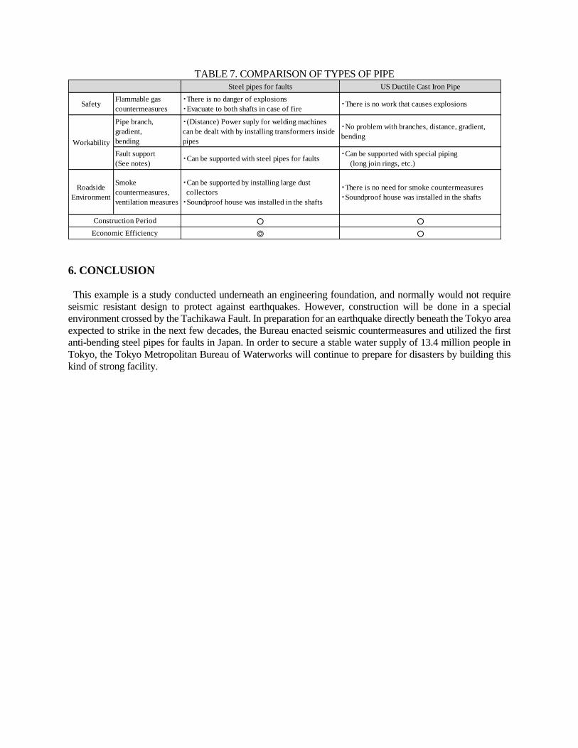
TABLE 7. COMPARISON OF TYPES OF PIPE
Steel pipes for faults US Ductile Cast Iron Pipe
SafetyFlammable gas
countermeasures
・There is no danger of explosions
・Evacuate to both shafts in case of fire・There is no work that causes explosions
Pipe branch,
gradient,
bending
・(Distance) Power suply for welding machines
can be dealt with by installing transformers inside
pipes
・No problem with branches, distance, gradient,
bending
Fault support
(See notes)・Can be supported with steel pipes for faults
・Can be supported with special piping
(long join rings, etc.)
Roadside
Environment
Smoke
countermeasures,
ventilation measures
・Can be supported by installing large dust
collectors
・Soundproof house was installed in the shafts
・There is no need for smoke countermeasures
・Soundproof house was installed in the shafts
○ ○
◎ ○
Workability
Construction Period
Economic Efficiency
6. CONCLUSION
This example is a study conducted underneath an engineering foundation, and normally would not require
seismic resistant design to protect against earthquakes. However, construction will be done in a special
environment crossed by the Tachikawa Fault. In preparation for an earthquake directly beneath the Tokyo area
expected to strike in the next few decades, the Bureau enacted seismic countermeasures and utilized the first
anti-bending steel pipes for faults in Japan. In order to secure a stable water supply of 13.4 million people in
Tokyo, the Tokyo Metropolitan Bureau of Waterworks will continue to prepare for disasters by building this
kind of strong facility.