Title of your Paper - iNEER - International Network for ... · Web viewO’Byrne, C. (1988) ‘The...
12
The new engineering building at NUI Galway as a 'living laboratory' for teaching and research 1 J. Goggins, 2 E. Cannon, 3 D. Byrne College of Engineering & Informatics, National University of Ireland, Galway, Ireland, [email protected] 1 ; [email protected] 2 ; [email protected] 3 Abstract The New Engineering Building (NEB) at NUIG will consolidate education and research activities in the various engineering disciplines into one building which will not only provide a learning environment, but will itself act as a teaching and learning tool. It will serve as a ‘living laboratory’ for engineering, where live data sets from numerous types of sensors will be used to illustrate structural engineering and building performance concepts in undergraduate teaching and in the development of full-scale research in structural engineering and energy. This paper describes the instrumentation of several major structural elements in order to provide the interactivity required of the ‘living laboratory’. Four elements were selected for instrumentation: a 40-tonne pre-tensioned box beam, a pre-tensioned double-tee unit, a novel void-formed two-way flat slab system and a structural steel hanging system. The processes of gauge selection, arrangement and installation are presented together some preliminary outcomes from the project. 1. Introduction Central to this project is the instrumentation of the New Engineering Building (NEB) at NUI Galway and its development as an interactive teaching tool for students. The NEB (Figure 1) will unite all engineering activities on campus into an exclusive, state of the art academic facility by September 2011. The building will not only provide a learning environment, but will itself act as a teaching and learning tool. It will be a ‘living laboratory’ for engineering, where live data sets from numerous types of sensors will be provided for use in illustrating structural engineering and building performance concepts in undergraduate teaching, and in the development of full- scale research in structural engineering and energy. Both energy and
Transcript of Title of your Paper - iNEER - International Network for ... · Web viewO’Byrne, C. (1988) ‘The...
The new engineering building at NUI Galway as a 'living laboratory' for teaching and research
1J. Goggins, 2E. Cannon, 3D. ByrneCollege of Engineering & Informatics, National University of Ireland, Galway, Ireland,
[email protected]; [email protected] 2; [email protected] 3
AbstractThe New Engineering Building (NEB) at NUIG will consolidate education and research activities in the various engineering disciplines into one building which will not only provide a learning environment, but will itself act as a teaching and learning tool. It will serve as a ‘living laboratory’ for engineering, where live data sets from numerous types of sensors will be used to illustrate structural engineering and building performance concepts in undergraduate teaching and in the development of full-scale research in structural engineering and energy. This paper describes the instrumentation of several major structural elements in order to provide the interactivity required of the ‘living laboratory’. Four elements were selected for instrumentation: a 40-tonne pre-tensioned box beam, a pre-tensioned double-tee unit, a novel void-formed two-way flat slab system and a structural steel hanging system. The processes of gauge selection, arrangement and installation are presented together some preliminary outcomes from the project.
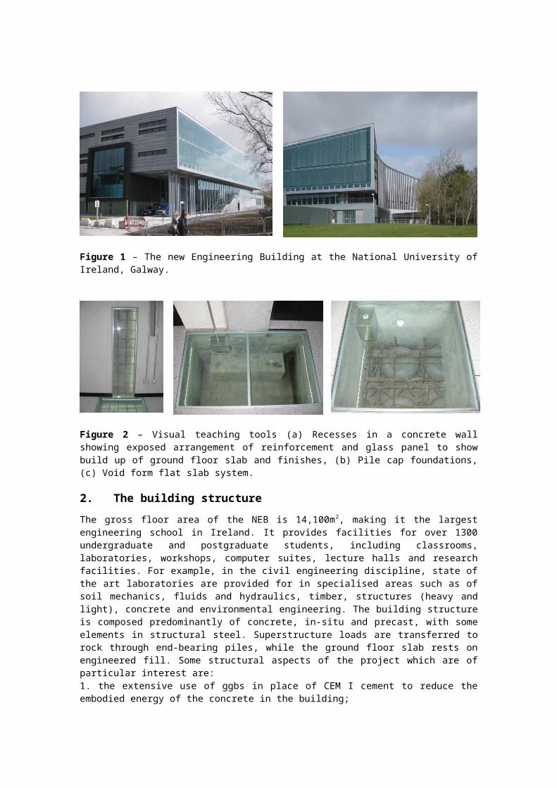
1. IntroductionCentral to this project is the instrumentation of the New Engineering Building (NEB) at NUI Galway and its development as an interactive teaching tool for students. The NEB (Figure 1) will unite all engineering activities on campus into an exclusive, state of the art academic facility by September 2011. The building will not only provide a learning environment, but will itself act as a teaching and learning tool. It will be a ‘living laboratory’ for engineering, where live data sets from numerous types of sensors will be provided for use in illustrating structural engineering and building performance concepts in undergraduate teaching, and in the development of full-scale research in structural engineering and energy. Both energy and structural characteristics of the structure are to be monitored throughout the building’s entire life cycle. As such, it will be beneficial for a number of engineering disciplines.
Data measuring the strains, temperatures and movements due to loading of the building will be gathered along with energy demands and performance of the building. Monitoring of the power consumption of different electrical loads such as lighting, computing and HVAC equipment will be performed, so that their relative energy costs can be demonstrated. The information gained from this instrumentation is being used to create interactive tools for students, form the basis for future research projects and facilitate the advancement of engineering teaching methods. The instrumentation will be used for a number of studies such as structural health monitoring and energy performance monitoring. Sensors will complement each other and all will be integrated into the overall Building Management System (BMS). The BMS will monitor properties such as carbon dioxide levels, temperature and humidity ensuring energy costs are kept at a minimum, but all the while maintaining a suitable environment for the occupier. The NEB itself contains a variety of green-building initiatives, such as the use of environmentally friendly heat generation

using carbon-neutral biomass, rain-water recycling, ground source heat pump, low embodied energy construction materials and high-tech renewable energy systems. These have been designed to reduce the buildings impact on the environment and make it as sustainable as possible. A number of structural elements have also been instrumented with over 260 gauges and sensors. These instrumented elements coupled with the green-building initiatives will provide working examples for engineering students to study. Several of the building’s constructional elements have consciously been left exposed, as visual learning tools (Figure 2) [1]. The vision is for a building whereby future students will be able to analyse and understand a building’s defining characteristics at first hand and on a personal level. This paper concentrates on an aspect of the development of the NEB as a ‘living laboratory’ for structural engineering, dealing in particular with the embedded sensors – both those requiring to be installed prior to erection of structural elements and those fixed during construction on the NEB site. These are fundamental to the development of the building as an interactive teaching tool, reporting on the evolving dialogue of the structure with its environment [2].
Figure 1 – The new Engineering Building at the National University of Ireland, Galway.
Figure 2 – Visual teaching tools (a) Recesses in a concrete wall showing exposed arrangement of reinforcement and glass panel to show build up of ground floor slab and finishes, (b) Pile cap foundations, (c) Void form flat slab system.
2. The building structureThe gross floor area of the NEB is 14,100m2, making it the largest engineering school in Ireland. It provides facilities for over 1300 undergraduate and postgraduate students, including classrooms, laboratories, workshops, computer suites, lecture halls and research facilities. For example, in the civil engineering discipline, state of the art laboratories are provided for in specialised areas such as of soil mechanics, fluids and hydraulics, timber, structures (heavy and
light), concrete and environmental engineering. The building structure is composed predominantly of concrete, in-situ and precast, with some elements in structural steel. Superstructure loads are transferred to rock through end-bearing piles, while the ground floor slab rests on engineered fill. Some structural aspects of the project which are of particular interest are:1. the extensive use of ggbs in place of CEM I cement to reduce the embodied energy of the concrete in the building;2. 40-tonne prestressed concrete transfer beams, precast by Banagher Concrete (Figure 3), positioned over the main lecture theatres;3. prestressed double-tee units, precast by Banagher Concrete;4. the Cobiax flooring system, a two-way spanning, void-formed, flat slab system utilising slabs manufactured by Oran Precast (Figure 4) and providing a high quality exposed soffit finish;5. deep structural steel plate girders, fabricated by Duggan Steel;6. a highly visible structural steel floor suspension system in one corner of the building (Figure 5).
The instrumentation described in this paper refers principally to items 2 to 4 above.
Figure 3 – 40-tonne prestressed transfer beam
Figure 4 – Void-formed flat slab system prior to installation
of top reinforcement mat.
Figure 5 – Structural steel floor suspension system during
construction.
3. Instrumentation
3.1 Objectives
The general intention was to monitor as many aspects as possible of the response of the selected elements to their environment. This would include response to discrete loading events, time-dependent variation in strain due to creep, shrinkage and temperature change, possible restraint effects in the large transfer beam and in the void formed slab system, and the load-sharing characteristics of the void formed slab system.
3.2 Test elements and sensor arrangement
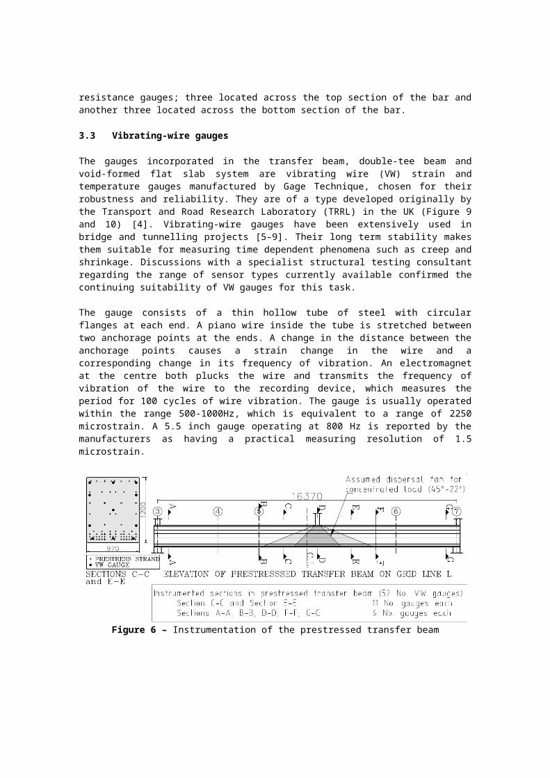
There was a severe time constraint in relation to the purchasing of gauges and datalogging equipment and also a significant time requirement for installation. Due to these factors and to budgetary constraints, instrumentation with embedded sensors was confined to three large-span elements. These were:(i) a pre-tensioned concrete transfer beam located on the 2nd floor on Grid line L from 3-7 (Figure 6);(ii) a pre-tensioned double-tee unit located adjacently on the 2nd floor between grid locations D3 to E7 (Figure 7);(iii) a two-way spanning void-formed flat slab flooring system on third floor between grid locations A9 to C10 (Figure 8);

Elements (i) and (ii) were instrumented with vibrating-wire (VW) gauges at Banagher Concrete’s premises, while element (iii) was instrumented with both VW and electrical resistance (ER) gauges, partly at Oran Precast’s premises and partly on the NEB site. A total of over 260 sensors and gauges were embedded within structural elements, in addition to temperature, carbon dioxide and humidity sensors in most rooms in the building and a weather station on the roof of the building. Novel technologies such as fibre-optic sensors and Tensiomag® - for use with prestressing tendons - were explored, but were not feasible in this instance for reasons of time and budget. It is envisaged that additional instrumentation (e.g. accelerometers, inclinometers) will be installed later in the programme to measure aspects of performance in use.
The transfer beam contains 52 VW gauges distributed over 7 sections, five of which are grouped around a concentrated load near midspan, while the other two are near the supports (Figure 6). Most sections contain six gauges - two at top, middle and bottom - but two of the sections contain eleven gauges with the intention of extracting fuller detail regarding strain and temperature variation within the beam. This 970 x 1200 deep beam is located over one of the main lecture theatres and, given its large mass, its role in the heating and cooling of the space will be of interest.
The double-tee (Figure 7) contains 39 gauges in all - 13 at each of 3 sections. The narrowness of the rib and the arrangement of prestressing strand meant that only one gauge could be placed at any given height within the rib, but there is mirroring of provision between ribs. Nine gauges are arranged across the flange, with the aim of picking up possible variations in compressive strain across the flange, associated with shear lag [3].
The NEB is the first building of its kind in Ireland to employ the void form flat slab system. These are an innovative and novel form of flat slab system. They consist of spherical void-formers, positioned in the middle of the concrete cross section to reduce the overall self weight of the slab, but maintain full flexural strength allowing a two-way or bi-axial load transfer (Figure 8). Gauges were installed to monitor temperature and strain in the slab element primarily to explore shear transfer and two-way load action in this unique slab system. Observation of the system over time will allow the performance of the system to be quantified, including changes to the material properties of the structural slab system. Further areas for research include the effect of the passive ventilation system on slab temperature and linking this to the thermal properties of the slab and analysing the different aspects affecting the thermal mass of the concrete slab. Furthermore, it will be possible to analyse the development and dissipation of heat of hydration of cement and the effect ground granulated blastfurnace slag (GGBS) has on reducing this phenomenon. The area highlighted for instrumentation was a 7.5 x 12.65m bay located on the 3rd Floor of the building. Details of the instrumentation can be seen in Figure 8 and 9. The slab itself had an overall thickness of 450mm incorporating 315mm diameter void formers. The slab was constructed using two separate elements, the bottom 65mm of the slab comprising of a pre-cast concrete element and the top 385mm consisting of in-situ concrete. The precast panels were transported to site in separate panels, typically 12m in length and 2.4m in width. To ensure that two-way action is achieved between the different slab panels a series of reinforcement or ‘stitching’ bars were provided. These ‘stitching’ bars were centred on the joint between the pre-cast elements. The assumption is that these will provide sufficient bond between the slab panels to ensure transfer of load across the slab joints rendering the joints irrelevant to the completed structural performance. In total 100 electrical resistance gauges were installed on twenty reinforcement bars. Ten bars were instrumented in the bottom pre-cast elements and a further ten on the ‘stitching’ bars in the in-situ slab element. In addition, a total of 64 vibrating wire gauges were installed across the slab bay.

The structural steel truss instrumented is located on the 3rd floor of the south wing, an important feature within the NEB (Figure 5). It impresses with a large glass front but also in the complex nature in which its corner is supported. Both the 2nd and 3rd floors have a 7.5 m long cantilever span which is supported using a complex structural system. Both slabs are suspended from two 193.7mm diameter x 12.5mm circular hollow sections, one at each corner of the slab bay. Encased within each circular hollow section is a M75 macalloy bar; the load from the slabs being transferred by means of a threaded nut bearing against steel washers onto a solid steel distribution plate. During construction the macalloy bars were prestressed to a predetermined load to support the system. Essentially the circular hollow section transfers the load from the 3rd and 2nd floors downward before transferring the load vertically via the macalloy bar where it is supported by a steel truss in one corner and a plate girder in the opposite corner, as seen in Figure 5. The macalloy bar supported by the steel truss was instrumented with a total of six electrical resistance gauges; three located across the top section of the bar and another three located across the bottom section of the bar.
3.3 Vibrating-wire gauges
The gauges incorporated in the transfer beam, double-tee beam and void-formed flat slab system are vibrating wire (VW) strain and temperature gauges manufactured by Gage Technique, chosen for their robustness and reliability. They are of a type developed originally by the Transport and Road Research Laboratory (TRRL) in the UK (Figure 9 and 10) [4]. Vibrating-wire gauges have been extensively used in bridge and tunnelling projects [5-9]. Their long term stability makes them suitable for measuring time dependent phenomena such as creep and shrinkage. Discussions with a specialist structural testing consultant regarding the range of sensor types currently available confirmed the continuing suitability of VW gauges for this task.
The gauge consists of a thin hollow tube of steel with circular flanges at each end. A piano wire inside the tube is stretched between two anchorage points at the ends. A change in the distance between the anchorage points causes a strain change in the wire and a corresponding change in its frequency of vibration. An electromagnet at the centre both plucks the wire and transmits the frequency of vibration of the wire to the recording device, which measures the period for 100 cycles of wire vibration. The gauge is usually operated within the range 500-1000Hz, which is equivalent to a range of 2250 microstrain. A 5.5 inch gauge operating at 800 Hz is reported by the manufacturers as having a practical measuring resolution of 1.5 microstrain.
Figure 6 – Instrumentation of the prestressed transfer beam

139.7 (5.5’’)
cable
electromagnet
Vibrating wireVibrating wireFlange
Protective cowl
Tensioned wireTube
6.3 (0.25’’)
38.1 (1.5’’)
Figure 7 – Instrumentation of the precast double tee unit
Figure 8 – Typical section of instrumentation in the void-formed flat slab system
Figure 9 – Vibrating wire gauges installed in void-formed flat slab in NEB
Figure 10 – Vibrating wire gauge.
3.4 Electrical resistance gauges
Electrical resistance gauges (Tokyo Sokki Kenkyujo model FLA-6-120-11-3LT) were used to determine the stresses in reinforcing bars embedded in the void-formed slabs. These gauges were installed on reinforcing bars in the Civil Engineering laboratory at NUIG at room temperature conditions. The reinforcing bar surface was prepared by removing thee ribs on the bars over a length of 25mm using a milling machine. The gauge was bonded to the bar using P2 TML strain gauge adhesive. A clamp was applied to the gauge and the adhesive was left to dry overnight, after which a VM waterproof tape was applied to protect from moisture and chemicals within the concrete. The reported operational life of the strain gauges and adhesive is a minimum of 30 years. All the gauges were tested in the laboratory before installing the bars on site. The gauges had 3m of 3-wire 0.11mm lead wire pre-connected; up to 15m lengths of 3-wire 0.5mm lead wires were used to 139.7 (5.5’’) connect these to the data acquisition system. The lead wires were installed inside plastic ducting within the concrete.
3.5 Data acquisition system
Campbell Scientific data acquisition system is used to acquire data from both types of gauge. The system for the pre-tensioned beams consists of a Campbell Scientific CR1000 datalogger. This is capable of controlling up to 128 VW gauges or 256 electrical resistance gauges through a series of AM16/32B multiplexers (up to 8 No. off, each capable of controlling up to 16 VW gauges or 32 electrical resistance gauges). In the case of VW gauges, a vibrating wire interface (AVW216) is required for each pair of multiplexers.
3.6 Installation
Installation of VW gauges is a laborious process which has to be fitted in around the work of joiners, steel fixers and general site operatives in preparation for pouring. The time required for installation will limit the scope of the instrumentation project unless the client is prepared for delays which will otherwise occur.
Survival of gauges and cabling is a concern before, during and after pouring. Where possible, cabling was bundled into PVC ducting within the element, and care taken where they emerged from the concrete. In the case of the transfer beam, poker vibrators represented a potential hazard to gauges and cabling, but due to the care taken by the precast concrete manufactures, Banagher Concrete, and the onsite operatives, there was no disablement of gauges on this score. Formwork for the double-tee beam had external vibrators, which presented no risk.
4. ConclusionsThe objective of the project was to instrument several elements in the new Engineering Building at the National University of Ireland, Galway so as to provide useful insight into the real time-varying behaviour of concrete and steel structures, for the benefit of undergraduate students and postgraduate researchers. It is considered that the proximity of the instrumented elements to lecturing spaces will confer a degree of immediacy on discussions of structural behaviour and energy performance, encouraging students to actively engage with the underlying engineering issues.
Instrumentation of the structural members described in Section 3.2 is now complete, and datasets are being continuously collected automatically on dataloggers. Various load tests have been carried out since their installation, and will be reported on later. Whilst analysis of results is at a preliminary stage, results to date display an encouraging level of consistency. Much interesting work remains to be done by way of analysis and ancillary testing before the potential benefits of this project are realised. However, the data generated from the embedded sensors has already led to a number of projects undertaken by final year undergraduate engineering students (for example, [10-12]), allowing these students to achieve a deeper understanding of structural elements. Furthermore, a postgraduate research student is also analysing shear transfer in void-formed flat slab systems, using insitu measurements from the embedded

sensors in the new Engineering Building. This project only started in the first quarter of 2010, but has already received international recognition that the research is of very high quality [13]. Many more undergraduate and postgraduate research projects, as well as smaller undergraduate projects embedded in various modules, will utilise data from the embedded sensors in the building’s structure. Furthermore, video and photographic records of the process of construction, installation and testing will be of continuing benefit in the education of future engineers in the new Engineering Building at NUI, Galway.
6. AcknowledgementsThis support of the New Engineering Building committee, the buildings office and members of the College of Engineering & Informatics (Energy Management Group and Building Structures Group) is gratefully acknowledged. Consultants ARUP and RMJM facilitated us at various stages. The success of a project of this nature is crucially dependent on the cooperation of people on site; in this respect we were most fortunate in relation to the main contractor, BAM Building, subcontractors Banagher Concrete and Oran Precast, and the resident engineer, who facilitated us throughout. The Civil Engineering technicians and postgraduate students at NUI, Galway played major parts in bringing this project to its present state. The third author is extremely grateful for the ongoing support of Arup Consulting Engineers and the Irish Research Council for Science, Engineering and Technology (IRCSET) through the Enterprise Partnership Scheme.
References1. RMJM (2008) ‘Teaching Tools’. Project report, RMJM Architects, Edinburgh, July 2008.
2. Cannon, E., Goggins, J. (2009) ‘Teaching tools – Instrumentation of New Engineering Building – Structural Engineering’. Internal report, College of Engineering & Informatics, NUI, Galway, 1 December 2009.
3. Moffat, K.R., Dowling, P.J. (1975) ‘Shear lag in steel box girder bridges’. The Structural Engineer, Oct 1975 pp. 439-448 (+ discussion Aug 1976 pp. 285-298)
4. Tyler, R.G. (1968) ‘Developments in the measurement of strain and stress in concrete bridge structures’. R.R.L. Report LR189, 1968
5. Tyler, R.G. (1973) ‘Long term strains in the Medway Bridge’. T.R.R.L. Report LR539, 1973.
6. Mortlock, J. D. (1974) The instrumentation of bridges for the measurement of temperature and movement. T.R.R.L. Report LR641, 1974
7. Barr, B.,Waldron, P., Evans, H.R. (1987) ‘Instrumentation of glued segmental box girder bridges’, Proceedings IABSE Colloquium, Bergamo, 1987, Monitoring of large structures and assessment of their safety.
8. O’Byrne, C. (1988) ‘The monitoring of strain in a prestressed concrete bridge of box girder construction’. MEngSc thesis, NUI, Galway, 1988
9. Cannon, E., O’Byrne, C. (2003) ‘In-situ instrumentation of concrete structures: a case study’. Proceedings, Colloquium on Concrete Research in Ireland, Queen’s University, Belfast, 2003.
10. Cotter M., Hurley P. (2011) ‘Evaluation of the Performance of a Prestressed Double Tee Concrete Unit Using Both Eurocode Provisions and In Situ Measurements’. BE thesis. National University of Ireland, Galway.
11. Goode M., O’Neill E. (2011) ‘The evaluation of the performance of a prestressed concrete transfer beam using both Eurocode provisions and insitu measurements’. BE thesis. National University of Ireland, Galway.
12. Houlihan J., Stack C. (2011) ‘The Modelling of hanging structural system in the New Engineering Building, NUI, Galway’. BE thesis. National University of Ireland, Galway.

13. Institute of Structural Engineers (2011) ‘The Young Researchers Conference’, Institute of Structural Engineers, Retrieved from the world wide web on 13 April 2011 at http://www.istructe.org/knowledge/topic_areas/research/yrc/Pages/default.aspx