TITLE OF PAPER - Foulingheatexchanger-fouling.com/.../papers2009/29_Abd-Elhady_F.pdfAbd-Elhady et...
9
INFLUENCE OF THE APEX ANGLE OF CONE SHAPED TUBES ON PARTICULATE FOULING OF HEAT EXCHANGERS M.S. Abd-Elhady 1 , C.C.M. Rindt 2 and A.A. van Steenhoven 2 1 Department of Mechanical Engineering, Beni-Suief University, Beni-Suief, Egypt, [email protected] 2 Department of Mechanical Engineering, Eindhoven University of Technology, P.O. Box 513, 5600 MB Eindhoven, The Netherlands. ABSTRACT A 2D cone shape has been added to the normal circular tubes of heat exchangers to minimize the area of stagnation and to stream line the air flow around the heat exchanger tubes. An experimental setup has been developed to study the influence of the apex angle of the cone shaped tubes on particulate fouling of heat exchangers. Fouling experiments have been performed in which calcium carbonate particles are injected during the experiments and the deposition of particles on the tubes of the heat exchanger is monitored. Four sets of experiments have been performed, in which normal cylindrical tubes and coned tubes with an apex angle of 60°, 90° and 120° are examined. It was found that particulate fouling ceased if the apex angle of the cone shaped tubes is smaller than 90°. The attached cones enhance the flow around the tubes of the heat exchanger, i.e. by minimizing the stagnation area and keeping the flow attached to the tubes starting from the tip of the attached cone until separation, such that particles which deposit on the top of the tubes of the heat exchanger can be removed by the air flow. INTRODUCTION One of the problems that faces the operation of heat exchangers is particulate fouling. Particulate fouling is defined as the accumulation of particles on a heat transfer surface that form an insulating layer, which reduces the rate of heat transfer and can lead to operation failure as has been reported by many researchers, e.g. in waste incinerators by van Beek et al. (2001), in a coal-fired power plant by Bryers (1996) and in utility scale boilers by Gupta et al. (1999). Transport and capture of particles on heat transfer surfaces are function of the size of particles, the chemical and physical properties of the transported particles, as well as the combustion system conditions, such as gas flow patterns, velocity, local temperature etc., Benson et al. (1993). A theoretical background about particulate fouling and especially gas side fouling can be found in literature of Epstein (1983, 1987) and Marner (1990). Many efforts have been made by numerous researchers to understand and control fouling in heat exchangers (Taborek et al., 1972; Müller-Steinhagen et al., 1988; Bohnet, 1987; Bott, 1995). Cylindrical tube bundles are used usually across major heat exchanger systems. Two standard tube bundle arrangements are commonly employed in industry, the staggered and the inline arrangement. The staggered arrangement is less prone to blockage due to fouling in comparison to the inline arrangement (Zukauskas, 1987), and that is due to higher turbulence levels in the staggered arrangement. However, the staggered arrangement exhibit higher pressure drop and larger energy consumption due to the increased pumping power required. Streamlined tubes, such as the oval and drop-shaped tubes (Merker and Hanke, 1986; Bouris et al., 2001), are used to over come pressure losses. Bouris et al. (2005) have examined the fouling behavior of such tubes, and found that stream lining the shape of the tubes resulted in 40 % lower pressure drop and 75 % lower deposition rate. However, the production of the streamlined tubes is expensive and complicated compared to circular tubes (Spin Tech Mufflers). Abd-Elhady et al. (2009) found that the best flow orientation to minimize particulate fouling in heat exchangers is the downward flow and that fouling starts at the stagnation area of flow. It can be concluded from the above literature survey that minimizing the stagnation area and streamlining the air flow around the heat exchangers tube can lead to a lower fouling propensity. The influence of minimizing the stagnation area of flow on particulate fouling of heat exchangers is investigated experimentally. Fouling experiments are performed in which cones made of steel are attached to the tubes of a heat exchanger to minimize the area of stagnation and to stream line the air flow around the heat exchanger tubes, and the fouling process is monitored. The influence of the apex angle of the attached cones on particulate fouling is investigated experimentally and analytically. EXPERIMENTAL SETUP AND THE EXPERIMENTAL PROCEDURE An experimental setup has been built to study the influence of streamlined tubes on particulate fouling of heat exchangers. A schematic of the experimental setup, which has been used, is shown in Fig. 1. The experimental setup consists of an air blower connected to a wooden duct of size 40cm×40cm×400cm. The power of the air blower is 1.5 kW at 1450 rpm, and delivers 0.25 m 3 /s of air at normal operating conditions. This results in a maximum velocity of 1.3 m/s. The experimental setup is vertically mounted such that the air flow is downwards in the direction of gravity. A screw particle feeder is used to dispatch calcium carbonate particles in the airflow, and varying the rotational speed of the screw of the particle feeder can vary the injection rate. Particles are injected at the inlet of the air blower, as shown in Fig. 1, to insure that the particles are uniformly distributed in the cross sectional area of airflow. The wooden duct contains a heat exchanger that contains 13 tubes arranged in a staggered matrix as shown in Fig. 1. The tubes are of diameter 3.2 Proceedings of International Conference on Heat Exchanger Fouling and Cleaning VIII - 2009 (Peer-reviewed) June 14-19, 2009, Schladming, Austria Editors: H. Müller-Steinhagen, M.R. Malayeri and A.P. Watkinson 200
Transcript of TITLE OF PAPER - Foulingheatexchanger-fouling.com/.../papers2009/29_Abd-Elhady_F.pdfAbd-Elhady et...

INFLUENCE OF THE APEX ANGLE OF CONE SHAPED TUBES ON PARTICULATE FOULING OF HEAT EXCHANGERS
M.S. Abd-Elhady 1, C.C.M. Rindt 2 and A.A. van Steenhoven 2
1Department of Mechanical Engineering, Beni-Suief University, Beni-Suief, Egypt, [email protected] 2Department of Mechanical Engineering, Eindhoven University of Technology, P.O. Box 513,
5600 MB Eindhoven, The Netherlands.
ABSTRACT A 2D cone shape has been added to the normal
circular tubes of heat exchangers to minimize the area of stagnation and to stream line the air flow around the heat exchanger tubes. An experimental setup has been developed to study the influence of the apex angle of the cone shaped tubes on particulate fouling of heat exchangers. Fouling experiments have been performed in which calcium carbonate particles are injected during the experiments and the deposition of particles on the tubes of the heat exchanger is monitored. Four sets of experiments have been performed, in which normal cylindrical tubes and coned tubes with an apex angle of 60°, 90° and 120° are examined. It was found that particulate fouling ceased if the apex angle of the cone shaped tubes is smaller than 90°. The attached cones enhance the flow around the tubes of the heat exchanger, i.e. by minimizing the stagnation area and keeping the flow attached to the tubes starting from the tip of the attached cone until separation, such that particles which deposit on the top of the tubes of the heat exchanger can be removed by the air flow. INTRODUCTION
One of the problems that faces the operation of heat exchangers is particulate fouling. Particulate fouling is defined as the accumulation of particles on a heat transfer surface that form an insulating layer, which reduces the rate of heat transfer and can lead to operation failure as has been reported by many researchers, e.g. in waste incinerators by van Beek et al. (2001), in a coal-fired power plant by Bryers (1996) and in utility scale boilers by Gupta et al. (1999). Transport and capture of particles on heat transfer surfaces are function of the size of particles, the chemical and physical properties of the transported particles, as well as the combustion system conditions, such as gas flow patterns, velocity, local temperature etc., Benson et al. (1993). A theoretical background about particulate fouling and especially gas side fouling can be found in literature of Epstein (1983, 1987) and Marner (1990). Many efforts have been made by numerous researchers to understand and control fouling in heat exchangers (Taborek et al., 1972; Müller-Steinhagen et al., 1988; Bohnet, 1987; Bott, 1995).
Cylindrical tube bundles are used usually across major heat exchanger systems. Two standard tube bundle arrangements are commonly employed in industry, the staggered and the inline arrangement. The staggered arrangement is less prone to blockage due to fouling in comparison to the inline arrangement (Zukauskas, 1987), and that is due to higher turbulence levels in the staggered
arrangement. However, the staggered arrangement exhibit higher pressure drop and larger energy consumption due to the increased pumping power required. Streamlined tubes, such as the oval and drop-shaped tubes (Merker and Hanke, 1986; Bouris et al., 2001), are used to over come pressure losses. Bouris et al. (2005) have examined the fouling behavior of such tubes, and found that stream lining the shape of the tubes resulted in 40 % lower pressure drop and 75 % lower deposition rate. However, the production of the streamlined tubes is expensive and complicated compared to circular tubes (Spin Tech Mufflers). Abd-Elhady et al. (2009) found that the best flow orientation to minimize particulate fouling in heat exchangers is the downward flow and that fouling starts at the stagnation area of flow. It can be concluded from the above literature survey that minimizing the stagnation area and streamlining the air flow around the heat exchangers tube can lead to a lower fouling propensity.
The influence of minimizing the stagnation area of flow on particulate fouling of heat exchangers is investigated experimentally. Fouling experiments are performed in which cones made of steel are attached to the tubes of a heat exchanger to minimize the area of stagnation and to stream line the air flow around the heat exchanger tubes, and the fouling process is monitored. The influence of the apex angle of the attached cones on particulate fouling is investigated experimentally and analytically.
EXPERIMENTAL SETUP AND THE EXPERIMENTAL PROCEDURE
An experimental setup has been built to study the influence of streamlined tubes on particulate fouling of heat exchangers. A schematic of the experimental setup, which has been used, is shown in Fig. 1. The experimental setup consists of an air blower connected to a wooden duct of size 40cm×40cm×400cm. The power of the air blower is 1.5 kW at 1450 rpm, and delivers 0.25 m3/s of air at normal operating conditions. This results in a maximum velocity of 1.3 m/s. The experimental setup is vertically mounted such that the air flow is downwards in the direction of gravity. A screw particle feeder is used to dispatch calcium carbonate particles in the airflow, and varying the rotational speed of the screw of the particle feeder can vary the injection rate. Particles are injected at the inlet of the air blower, as shown in Fig. 1, to insure that the particles are uniformly distributed in the cross sectional area of airflow. The wooden duct contains a heat exchanger that contains 13 tubes arranged in a staggered matrix as shown in Fig. 1. The tubes are of diameter 3.2
Proceedings of International Conference on Heat Exchanger Fouling and Cleaning VIII - 2009 (Peer-reviewed) June 14-19, 2009, Schladming, Austria Editors: H. Müller-Steinhagen, M.R. Malayeri and A.P. Watkinson
200
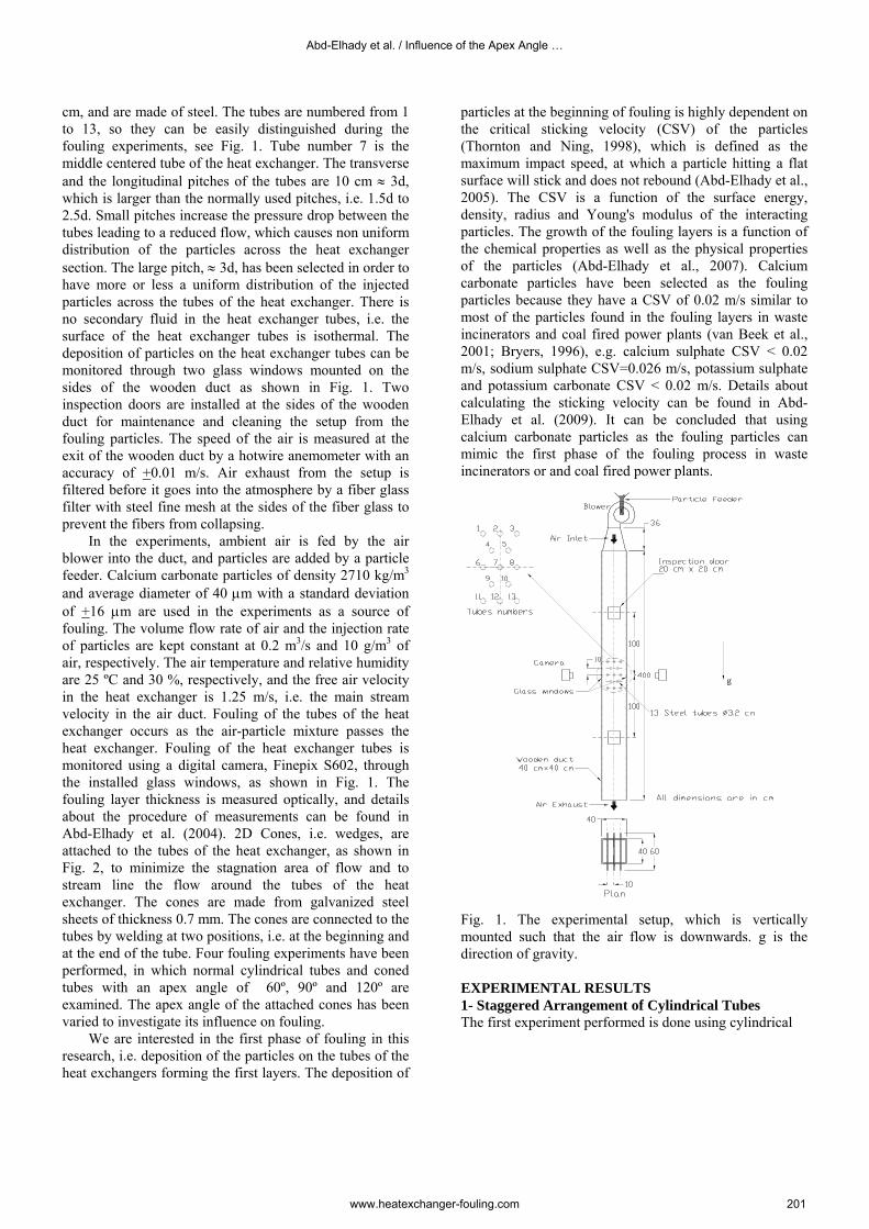
cm, and are made of steel. The tubes are numbered from 1 to 13, so they can be easily distinguished during the fouling experiments, see Fig. 1. Tube number 7 is the middle centered tube of the heat exchanger. The transverse and the longitudinal pitches of the tubes are 10 cm ≈ 3d, which is larger than the normally used pitches, i.e. 1.5d to 2.5d. Small pitches increase the pressure drop between the tubes leading to a reduced flow, which causes non uniform distribution of the particles across the heat exchanger section. The large pitch, ≈ 3d, has been selected in order to have more or less a uniform distribution of the injected particles across the tubes of the heat exchanger. There is no secondary fluid in the heat exchanger tubes, i.e. the surface of the heat exchanger tubes is isothermal. The deposition of particles on the heat exchanger tubes can be monitored through two glass windows mounted on the sides of the wooden duct as shown in Fig. 1. Two inspection doors are installed at the sides of the wooden duct for maintenance and cleaning the setup from the fouling particles. The speed of the air is measured at the exit of the wooden duct by a hotwire anemometer with an accuracy of +0.01 m/s. Air exhaust from the setup is filtered before it goes into the atmosphere by a fiber glass filter with steel fine mesh at the sides of the fiber glass to prevent the fibers from collapsing.
In the experiments, ambient air is fed by the air blower into the duct, and particles are added by a particle feeder. Calcium carbonate particles of density 2710 kg/m3 and average diameter of 40 µm with a standard deviation of +16 µm are used in the experiments as a source of fouling. The volume flow rate of air and the injection rate of particles are kept constant at 0.2 m3/s and 10 g/m3 of air, respectively. The air temperature and relative humidity are 25 ºC and 30 %, respectively, and the free air velocity in the heat exchanger is 1.25 m/s, i.e. the main stream velocity in the air duct. Fouling of the tubes of the heat exchanger occurs as the air-particle mixture passes the heat exchanger. Fouling of the heat exchanger tubes is monitored using a digital camera, Finepix S602, through the installed glass windows, as shown in Fig. 1. The fouling layer thickness is measured optically, and details about the procedure of measurements can be found in Abd-Elhady et al. (2004). 2D Cones, i.e. wedges, are attached to the tubes of the heat exchanger, as shown in Fig. 2, to minimize the stagnation area of flow and to stream line the flow around the tubes of the heat exchanger. The cones are made from galvanized steel sheets of thickness 0.7 mm. The cones are connected to the tubes by welding at two positions, i.e. at the beginning and at the end of the tube. Four fouling experiments have been performed, in which normal cylindrical tubes and coned tubes with an apex angle of 60º, 90º and 120º are examined. The apex angle of the attached cones has been varied to investigate its influence on fouling.
We are interested in the first phase of fouling in this research, i.e. deposition of the particles on the tubes of the heat exchangers forming the first layers. The deposition of
particles at the beginning of fouling is highly dependent on the critical sticking velocity (CSV) of the particles (Thornton and Ning, 1998), which is defined as the maximum impact speed, at which a particle hitting a flat surface will stick and does not rebound (Abd-Elhady et al., 2005). The CSV is a function of the surface energy, density, radius and Young's modulus of the interacting particles. The growth of the fouling layers is a function of the chemical properties as well as the physical properties of the particles (Abd-Elhady et al., 2007). Calcium carbonate particles have been selected as the fouling particles because they have a CSV of 0.02 m/s similar to most of the particles found in the fouling layers in waste incinerators and coal fired power plants (van Beek et al., 2001; Bryers, 1996), e.g. calcium sulphate CSV < 0.02 m/s, sodium sulphate CSV=0.026 m/s, potassium sulphate and potassium carbonate CSV < 0.02 m/s. Details about calculating the sticking velocity can be found in Abd-Elhady et al. (2009). It can be concluded that using calcium carbonate particles as the fouling particles can mimic the first phase of the fouling process in waste incinerators or and coal fired power plants.
Fig. 1. The experimental setup, which is vertically mounted such that the air flow is downwards. g is the direction of gravity. EXPERIMENTAL RESULTS 1- Staggered Arrangement of Cylindrical Tubes The first experiment performed is done using cylindrical
Abd-Elhady et al. / Influence of the Apex Angle …
www.heatexchanger-fouling.com 201

Fig. 2. The coned tubes used in the fouling experiments: a) apex angle 60º, b) apex angle 90º and c) apex angle 120º. The cones are pointing upwards.
Fig. 3. The staggered arrangement of the heat exchanger tubes. Tube 7 is the middle centered tube of the heat exchanger.
Fig. 4. Particulate fouling of the tubes 4, 6 and 7, as a function of time. The air flow is downwards and g is the direction of gravity. The white color represents the fouling layer of calcium carbonate particles, and the black color the tube surface.
Heat Exchanger Fouling and Cleaning VIII – 2009
www.heatexchanger-fouling.com 202
tubes arranged in a staggered arrangement as shown in Fig. 1, and as presented in Fig. 3. The first row of tubes, i.e. tubes 1, 2 and 3 are not seen in fig. 3. Fouling of the tubes 4, 6 and 7 as a function of time is shown in fig. 4. It can be seen that the bottom of tube 4 has not fouled, however, the top of tubes 6 and 7 fouled from the beginning of the experiment and continued fouling till the end of the experiment. It has been noticed that fouling started at the top of the tubes, i.e. the stagnation area of flow, and continued to build up circumferentially, which is in agreement with the observations of Abd-Elhady et al., (2009). The stagnation area is minimized in the next experiments by adding cones at the top of the heat exchangers tubes, and the influence of such cones on particulate fouling is examined. 2- Staggered Arrangement of Coned Tubes with an Apex Angle of 60º
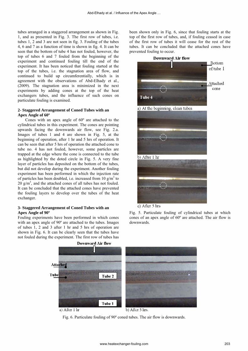
Cones with an apex angle of 60º are attached to the cylindrical tubes in this experiment. The cones are pointing upwards facing the downwards air flow, see Fig. 2.a. Images of tubes 1 and 4 are shown in Fig. 5, at the beginning of operation, after 1 hr and 5 hrs of operation. It can be seen that after 5 hrs of operation the attached cone to tube no. 4 has not fouled, however, some particles are trapped at the edge where the cone is connected to the tube as highlighted by the doted circle in Fig. 5. A very fine layer of particles has deposited on the bottom of the tubes, but did not develop during the experiment. Another fouling experiment has been performed in which the injection rate of particles has been doubled, i.e. increased from 10 g/m3 to 20 g/m3, and the attached cones of all tubes has not fouled. It can be concluded that the attached cones have prevented the fouling layers to develop over the tubes of the heat exchanger.
3- Staggered Arrangement of Coned Tubes with an Apex Angle of 90º Fouling experiments have been performed in which cones with an apex angle of 90º are attached to the tubes. Images of tubes 1, 2 and 3 after 1 hr and 5 hrs of operation are shown in Fig. 6. It can be clearly seen that the tubes have not fouled during the experiment. The first row of tubes has
been shown only in Fig. 6, since that fouling starts at the top of the first row of tubes, and, if fouling ceased in case of the first row of tubes it will cease for the rest of the tubes. It can be concluded that the attached cones have prevented fouling to occur.
Fig. 5. Particulate fouling of cylindrical tubes at which cones of an apex angle of 60º are attached. The air flow is downwards.
Fig. 6. Particulate fouling of 90º coned tubes. The air flow is downwards.
Abd-Elhady et al. / Influence of the Apex Angle …
www.heatexchanger-fouling.com 203
4- Staggered arrangement of coned tubes with an apex angle of 120º
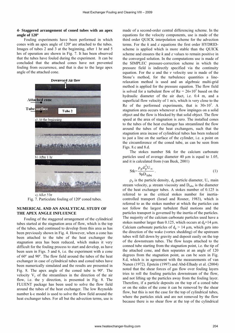
Fouling experiments have been performed in which cones with an apex angle of 120º are attached to the tubes. Images of tubes 2 and 3 at the beginning, after 1 hr and 5 hrs of operation are shown in Fig. 7. It has been observed that the tubes have fouled during the experiment. It can be concluded that the attached cones have not prevented fouling from occurrence, and that is due to the large apex angle of the attached cone.
Fig. 7. Particulate fouling of 120º coned tubes.
NUMERICAL AND AN ANALYTICAL STUDY OF THE APEX ANGLE INFLUENCE
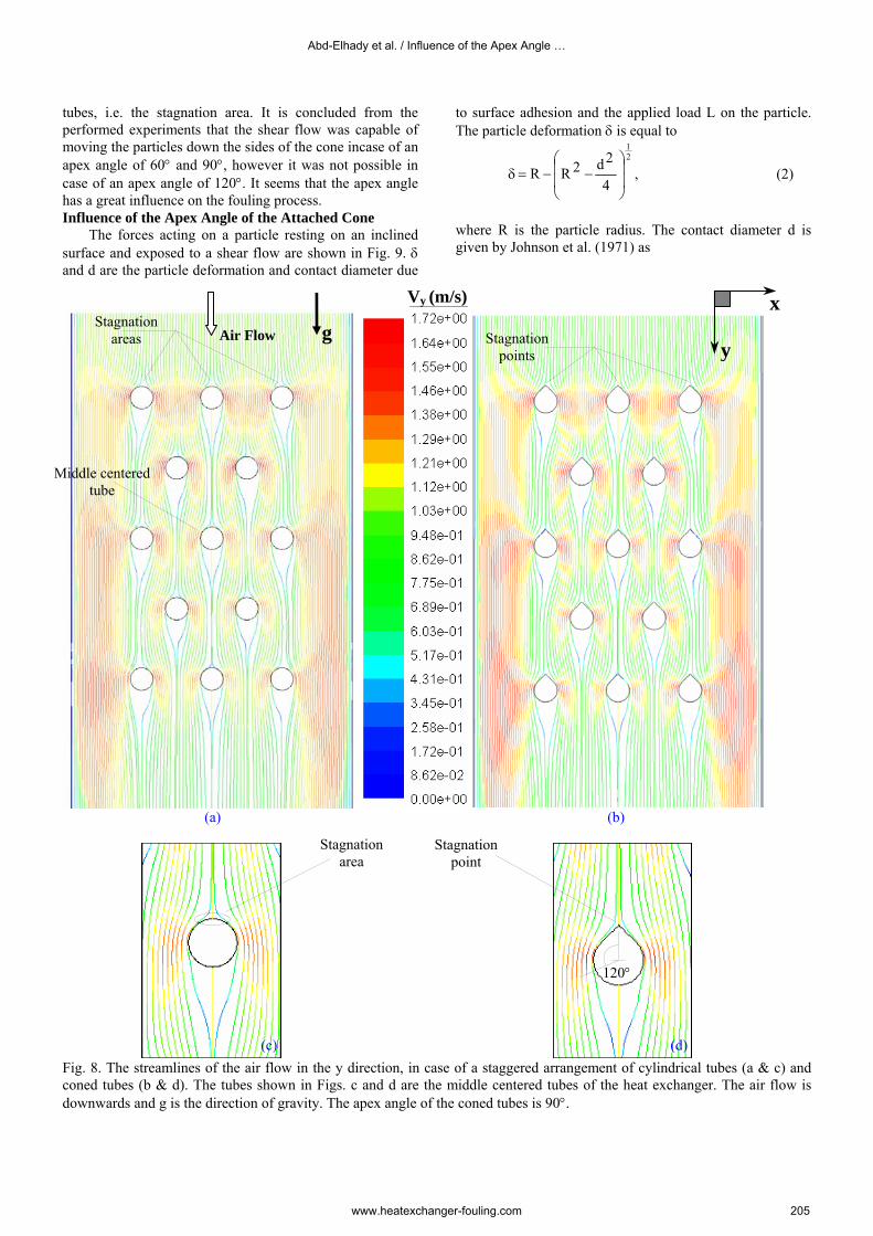
Fouling of the staggered arrangement of the cylindrical tubes started at the stagnation area of flow, which is the top of the tubes, and continued to develop from this area as has been previously shown in Fig. 4. However, when a cone has been attached to the tube of the heat exchanger the stagnation area has been reduced, which makes it very difficult for the fouling process to start and develop, as have been seen in Figs. 5 and 6, i.e. the experiment with a cone of 60° and 90°. The flow field around the tubes of the heat exchanger in case of cylindrical tubes and coned tubes have been numerically simulated and the results are presented in Fig. 8. The apex angle of the coned tube is 90°. The velocity Vy of the streamlines in the direction of the air flow, i.e. the y direction, is presented in Fig. 8. The FLUENT package has been used to solve the flow field around the tubes of the heat exchanger. The low Reynolds number k-ε model is used to solve the flow field around the heat exchanger tubes. For all but the advection terms, use is
made of a second-order central differencing scheme. In the equations for the velocity components, use is made of the third order QUICK interpolation scheme for the advection terms. For the k and ε equations the first order HYDRID-scheme is applied which is more stable than the QUICK scheme and ensures the k and ε values to remain positive in the converged solution. In the computations use is made of the SIMPLEC pressure-correction scheme in which the pressure field is indirectly specified via the continuity equation. For the u and the v velocity use is made of the Stone’s method, for the turbulence quantities a line-relaxation method is used and an algebraic multi-grid method is applied for the pressure equation. The flow field is solved for a turbulent flow of Re = 26×103 based on the hydraulic diameter of the air duct, i.e. 0.4 m, and a superficial flow velocity of 1 m/s, which is very close to the Re of the performed experiments, that is 30×103. A stagnation area occurs whenever a flow impinges on a solid object and the flow is blocked by that solid object. The flow speed at the area of stagnation is zero. The installed cones to the tubes of the heat exchanger has streamlined the flow around the tubes of the heat exchangers, such that the stagnation area incase of cylindrical tubes has been reduced to just a line on the surface of the cylinder, i.e. a point on the circumference of the coned tube, as can be seen from Figs. 8.c and 8.d.
The stokes number Stk for the calcium carbonate particles used of average diameter 40 µm is equal to 1.05, and it is calculated from (van Beek, 2001)
Stk=tube
2pp
Dµ9
Udρ ∞ . (1)
ρp is the particle density, dp particle diameter, U∞ main stream velocity, µ stream viscosity and Dtube is the diameter of the heat exchanger tubes. A stokes number of 0.125 is referred to as the critical stokes number for inertia-controlled transport (Israel and Rosner, 1983), which is referred to as the stokes number at which the particles can not follow the largest turbulent fluid motions and the particles transport is governed by the inertia of the particles. The majority of the calcium carbonate particles used have a stokes number larger than 0.125, which occurs at dp=14 µm. Calcium carbonate particles of dp > 14 µm, which gets into the direction of the wake (vortex shedding) of the upstream tubes will fall down by gravity and deposit easily on the top of the downstream tubes. The flow keeps attached to the conned tube starting from the stagnation point, i.e. the tip of the attached cone, and then separates at an angle of 120 degrees from the stagnation point, as can be seen in Fig. 8.d, which is in agreement with the measurements of van Nunen (1972). Epstein (1997) and Abd-Elhady et al. (2004) noted that the shear forces of gas flow over fouling layers tries to roll the fouling particles downstream of the flow, and not lifting up the particles away from the fouling layer. Therefore, if a particle deposits on the top of a coned tube or on the sides of the cone it can be removed by the shear flow, but this is not the case for the top of cylindrical tubes, where the particles stick and are not removed by the flow because there is no shear flow at the top of the cylindrical
Heat Exchanger Fouling and Cleaning VIII – 2009
www.heatexchanger-fouling.com 204
tubes, i.e. the stagnation area. It is concluded from the performed experiments that the shear flow was capable of moving the particles down the sides of the cone incase of an apex angle of 60° and 90°, however it was not possible in case of an apex angle of 120°. It seems that the apex angle has a great influence on the fouling process. Influence of the Apex Angle of the Attached Cone
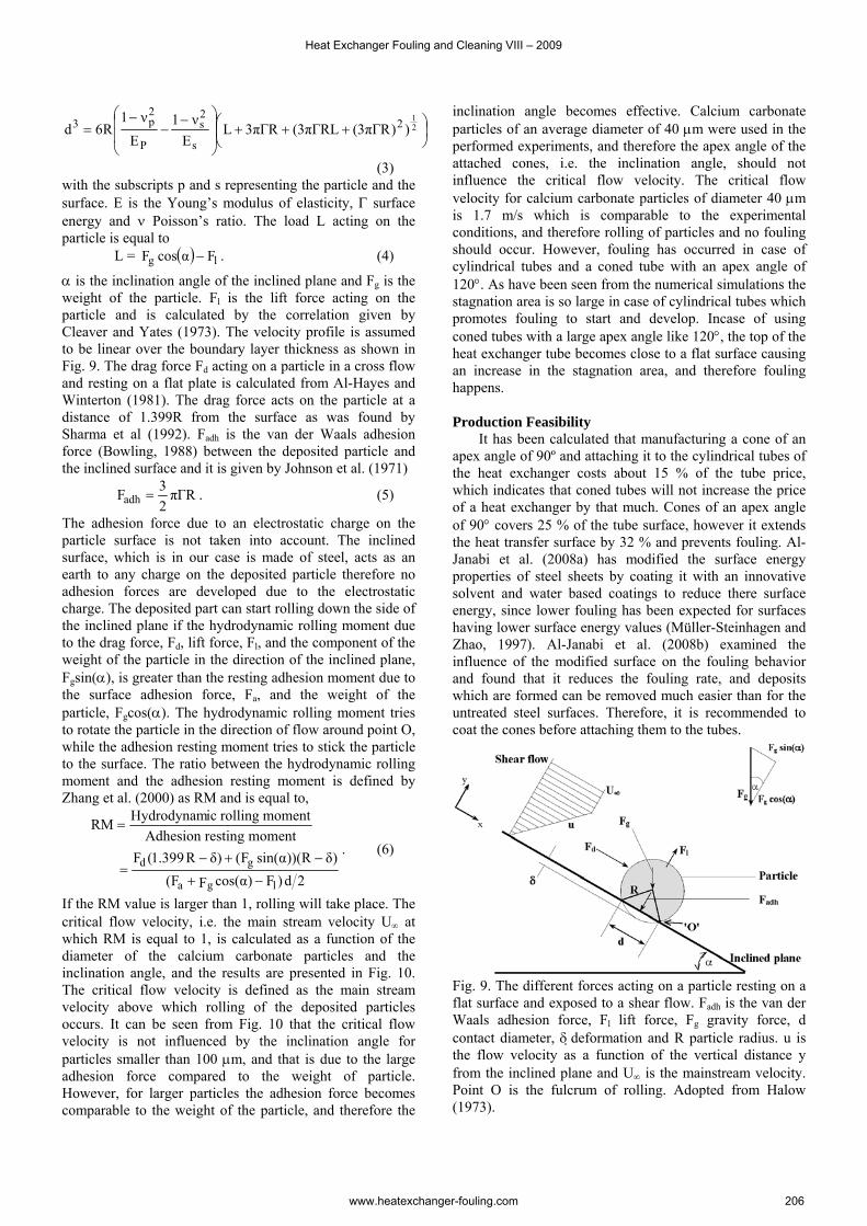
The forces acting on a particle resting on an inclined surface and exposed to a shear flow are shown in Fig. 9. δ and d are the particle deformation and contact diameter due
to surface adhesion and the applied load L on the particle. The particle deformation δ is equal to
δ21
4
2d2RR ⎟⎟
⎠
⎞
⎜⎜
⎝
⎛−−= , (2)
where R is the particle radius. The contact diameter d is given by Johnson et al. (1971) as
Vy (m/s)
(
Fig. 8. The streamlines oconed tubes (b & d). Thdownwards and g is the d
xStagnation
Stagnation areas g
Middle centered tube
Abd-Elhady et al. / Influence of the Apex Angle …
Air Flow
a) (b)
f the air flow in the y direction, in case of a staggered arrangement of cylindrical tubes (a & c) and e tubes shown in Figs. c and d are the middle centered tubes of the heat exchanger. The air flow is irection of gravity. The apex angle of the coned tubes is 90°.
ypoints
Stagnation area
Stagnation point
120°
(c) (d)
www.heatexchanger-fouling.com 205
⎟⎠⎞
⎜⎝⎛ +++⎟
⎟
⎠
⎞
⎜⎜
⎝
⎛ −−
−= 2
1))RΓπ3(RLΓπ3(RΓπ3L
Eν1
Eν1
R6d 2
s
2s
P
2p3
(3) with the subscripts p and s representing the particle and the surface. E is the Young’s modulus of elasticity, Γ surface energy and ν Poisson’s ratio. The load L acting on the particle is equal to
L = . (4) ( ) lg FαcosF −
α is the inclination angle of the inclined plane and Fg is the weight of the particle. Fl is the lift force acting on the particle and is calculated by the correlation given by Cleaver and Yates (1973). The velocity profile is assumed to be linear over the boundary layer thickness as shown in Fig. 9. The drag force Fd acting on a particle in a cross flow and resting on a flat plate is calculated from Al-Hayes and Winterton (1981). The drag force acts on the particle at a distance of 1.399R from the surface as was found by Sharma et al (1992). Fadh is the van der Waals adhesion force (Bowling, 1988) between the deposited particle and the inclined surface and it is given by Johnson et al. (1971)
RΓπ23Fadh = . (5)
The adhesion force due to an electrostatic charge on the particle surface is not taken into account. The inclined surface, which is in our case is made of steel, acts as an earth to any charge on the deposited particle therefore no adhesion forces are developed due to the electrostatic charge. The deposited part can start rolling down the side of the inclined plane if the hydrodynamic rolling moment due to the drag force, Fd, lift force, Fl, and the component of the weight of the particle in the direction of the inclined plane, Fgsin(α), is greater than the resting adhesion moment due to the surface adhesion force, Fa, and the weight of the particle, Fgcos(α). The hydrodynamic rolling moment tries to rotate the particle in the direction of flow around point O, while the adhesion resting moment tries to stick the particle to the surface. The ratio between the hydrodynamic rolling moment and the adhesion resting moment is defined by Zhang et al. (2000) as RM and is equal to,
2d)F)αcos(FF()δR))(αsin(F()δR399.1(F
momentrestingAdhesionmomentrollingicHydrodynamRM
lga
gd
−+
−+−=
=
. (6)
If the RM value is larger than 1, rolling will take place. The critical flow velocity, i.e. the main stream velocity U∞ at which RM is equal to 1, is calculated as a function of the diameter of the calcium carbonate particles and the inclination angle, and the results are presented in Fig. 10. The critical flow velocity is defined as the main stream velocity above which rolling of the deposited particles occurs. It can be seen from Fig. 10 that the critical flow velocity is not influenced by the inclination angle for particles smaller than 100 µm, and that is due to the large adhesion force compared to the weight of particle. However, for larger particles the adhesion force becomes comparable to the weight of the particle, and therefore the
inclination angle becomes effective. Calcium carbonate particles of an average diameter of 40 µm were used in the performed experiments, and therefore the apex angle of the attached cones, i.e. the inclination angle, should not influence the critical flow velocity. The critical flow velocity for calcium carbonate particles of diameter 40 µm is 1.7 m/s which is comparable to the experimental conditions, and therefore rolling of particles and no fouling should occur. However, fouling has occurred in case of cylindrical tubes and a coned tube with an apex angle of 120°. As have been seen from the numerical simulations the stagnation area is so large in case of cylindrical tubes which promotes fouling to start and develop. Incase of using coned tubes with a large apex angle like 120°, the top of the heat exchanger tube becomes close to a flat surface causing an increase in the stagnation area, and therefore fouling happens. Production Feasibility
It has been calculated that manufacturing a cone of an apex angle of 90º and attaching it to the cylindrical tubes of the heat exchanger costs about 15 % of the tube price, which indicates that coned tubes will not increase the price of a heat exchanger by that much. Cones of an apex angle of 90° covers 25 % of the tube surface, however it extends the heat transfer surface by 32 % and prevents fouling. Al-Janabi et al. (2008a) has modified the surface energy properties of steel sheets by coating it with an innovative solvent and water based coatings to reduce there surface energy, since lower fouling has been expected for surfaces having lower surface energy values (Müller-Steinhagen and Zhao, 1997). Al-Janabi et al. (2008b) examined the influence of the modified surface on the fouling behavior and found that it reduces the fouling rate, and deposits which are formed can be removed much easier than for the untreated steel surfaces. Therefore, it is recommended to coat the cones before attaching them to the tubes.
Fig. 9. The different forces acting on a particle resting on a flat surface and exposed to a shear flow. Fadh is the van der Waals adhesion force, Fl lift force, Fg gravity force, d contact diameter, δ deformation and R particle radius. u is the flow velocity as a function of the vertical distance y from the inclined plane and U∞ is the mainstream velocity. Point O is the fulcrum of rolling. Adopted from Halow (1973).
Heat Exchanger Fouling and Cleaning VIII – 2009
www.heatexchanger-fouling.com 206
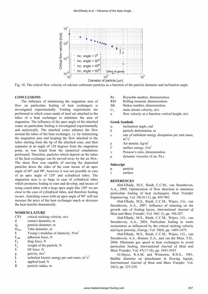
Fig. 10. The critical flow velocity of calcium carbonate particles as a function of the particle diameter and inclination angle. CONCLUSIONS
The influence of minimizing the stagnation area of flow on particulate fouling of heat exchangers is investigated experimentally. Fouling experiments are performed in which cones made of steel are attached to the tubes of a heat exchanger to minimize the area of stagnation. The influence of the apex angle of the attached cones on particulate fouling is investigated experimentally and analytically. The attached cones enhance the flow around the tubes of the heat exchanger, i.e. by minimizing the stagnation area and keeping the flow attached to the tubes starting from the tip of the attached cone, and then separates at an angle of 120 degrees from the stagnation point, as was found from the numerical simulations performed. Therefore, particles which deposit on the tubes of the heat exchanger can be moved away by the air flow. The shear flow was capable of moving the deposited particles down the sides of the cone incase of an apex angle of 60° and 90°, however it was not possible in case of an apex angle of 120° and cylindrical tubes. The stagnation area is so large in case of cylindrical tubes which promotes fouling to start and develop, and incase of using coned tubes with a large apex angle like 120° we are close to the case of cylindrical tubes, and therefore fouling occurs. Attaching cones with an apex angle of 90° will not increase the price of the heat exchanger much or decrease the heat transfer dramatically.
NOMENCLATURE CSV critical sticking velocity, m/s d contact diameter, m dp particle diameter, m Dtube Tube diameter, m E Young’s modulus of elasticity, N/m2 Fadh adhesion force, N Fd drag force, N Fg weight of the particle, N Fl lift force, N g gravity, m/s2 k turbulent kinetic energy per unit mass, m2/s2 L applied load, N R particle radius, m
Re Reynolds number, dimensionless RM Rolling moment, dimensionless Stk Stokes number, dimensionless U∞ main stream velocity, m/s u flow velocity as a function vertical height, m/s Greek Symbols α inclination angle, rad δ particle deformation, m ε rate of turbulent energy dissipation per unit mass,
m2/s3 ρ Air density, kg/m3 Γ surface energy, J/m2 ν Poisson’s ratio, dimensionless µ dynamic viscosity of air, Pa.s Subscript p particle s surface REFERENCES
Abd-Elhady, M.S., Rindt, C.C.M., van Steenhoven, A.A., 2009, Optimization of flow direction to minimize particulate fouling of heat exchangers, Heat Transfer Engineering, Vol. 30(10-11), pp. 895-902.
Abd-Elhady, M.S., Rindt, C.C.M., Wijers, J.G., van Steenhoven, A.A., 2007, Influence of sintering on the growth rate of fouling layers, International Journal of Heat and Mass Transfer, Vol. 50(1-2), pp. 196-207.
Abd-Elhady, M.S., Rindt, C.C.M., Wijers, J.G., van Steenhoven, A.A., 2005, Particulate fouling in waste incinerators as influenced by the critical sticking velocity and layer porosity, Energy, Vol. 30(8), pp. 1469-1479.
Abd-Elhady, M.S., Rindt, C.C.M., Wijers, J.G., van Steenhoven, A.A., Bramer, E.A., and van der Meer, T.H., 2004, Minimum gas speed in heat exchangers to avoid particulate fouling, International Journal of Heat and Mass Transfer, Vol. 47(17-18), pp. 3943-3955.
Al-Hayes, R.A.M, and Winterton, R.H.S., 1981, Bubble diameter on detachment in flowing liquids, International Journal of Heat and Mass Transfer, Vol. 24(2), pp. 223-230.
Abd-Elhady et al. / Influence of the Apex Angle …
www.heatexchanger-fouling.com 207

Al-Janabi, A., Malayeri, M.R., Müller-Steinhagen, H., 2008a, Application of innovative organic/inorganic coatings for the mitigation of crystallization fouling, Proceedings of the Condition Monitoring and Diagnostic Engineering Management conference, Prague, Czech Republic, pp. 11-18.
Al-Janabi, A., Malayeri, M.R., Müller-Steinhagen, H., 2008b, Experimental Investigation of Fortified PFA Coatings for the Mitigation of Crystallization Fouling, Proceedings of the 17th International Federation for Heat Treatment and Surface Engineering (IFHTSE) Congress, Kobe, Japan, pp. 27-30.
Benson, S.A., Jones, M.L., and Harb, J.N., 1993, Ash formation and deposition, in Fundamental of Coal Combustion – for Clean and Efficient Use, Coal Science and Technology, ed. L.D. Smoot, Elsevier Science Publishers, Amsterdam, ISBN 0-444-89643-0, chapter 4, pp. 299-373.
Bohnet, M., 1987, Fouling of heat-transfer surfaces, Chemical Engineering Technology, Vol. 10, pp. 113-125.
Bott, T.R., 1995, The Fouling of Heat Exchangers, Elsevier Science, New York.
Bouris, D., Papadakis, G., Bergeles, G., 2001, Numerical evaluation of alternate tube bundle configuration for particle deposition rate reduction in heat exchanger tube budles, International Journal of Heat and Fluid Flow, Vol. 22(5), pp. 525-536.
Bouris, D., Konstantinidis, E., Balabani, S., Castiglia, D., Bergeles, G., 2005, Design of a novel, intensified heat exchanger for reduced fouling rates, International Journal of Heat and Mass transfer, Vol. 48(18), pp. 3817-3832.
Bowling, R.A., 1988, A theoretical review of particle adhesion, Particles on Surfaces, Part 1: Detection, Adhesion and Removal, ed. K.L. Mittal, pp. 129-142, Plenum Press, New York.
Bryers, R.W., 1996, Fireside slagging, fouling, and high-temperature corrosion of heat-transfer surface due to impurities in steam-raising fuels, Progress in Energy and Combustion Science, Vol. 22(1), pp. 29-120.
Cleaver, J.W., and Yates, B., 1973, Mechanism of detachment of colloidal particles from a flat substrate in a turbulent Flow, Journal of Colloid and Interface Science, Vol. 44 (3), pp. 464-474.
Epstein, N., 1983, Thinking about heat transfer fouling: a 5 × 5 matrix, Heat Transfer Engineering, Vol. 4(1), pp. 43-56.
Epstein, N., 1987, Fouling in heat exchangers in: Proceedings of the 6th International Heat Transfer Conference, pp. 235-253.
Epstein, N., 1997, Elements of particle deposition onto nonporous solid surfaces parallel to suspension flows, Experimental Thermal and Fluid Science, Vol. 14(4), pp. 323-334.
Gupta, R.P., Wall, T.F., Baxter, L.L., 1999, The thermal conductivity of coal ash deposits: relationships for particulate and slag structures, in: Gupta, R.P., Wall, T.F., Baxter, L.L., (Eds.), The Impact of Mineral Impurities in Solid Fuel Combustion, Kluwer Academic Press, New York, pp. 65-84.
Halow, J.S., 1973, Incipient rolling, sliding and suspension of particles in horizontal and inclined turbulent flow, Chemical Engineering Science, Vol. 28(1), pp. 1-12.
Israel, R., Rosner, D.E., 1983, Use of a generalized Stokes number to determine the aerodynamic capture efficiency of non-Stokesian particles from a compressible gas flow, Aerosol Sc. and Technology, vol. 2, pp. 45-51.
Johnson, K.L., Kendall, K., and Roberts, A.D., 1971, Surface energy and the contact of elastic solids, Proceedings Royal Society A, Vol. 324, pp. 301-313.
Marner, W.J., 1990, Progress in gas-side fouling of heat-transfer surfaces, Applied Mechanics Review, Vol. 43(1), pp. 35-66.
Merker, G.P., Hanke, H., 1986, Heat transfer and pressure drop along the shell side of tube banks having oval-shaped tubes, International Journal of Heat and Mass transfer, Vol. 29(12), pp. 1903-1909.
Müller-Steinhagen, H., Reif, F., Epstein, N., and Watkinson, P., 1988, Influence of operating conditions on particulate fouling, The Canadian Journal of Chemical Engineering, Vol. 66, pp. 42-50.
Müller-Steinhagen, H., Zhao, Q., 1997, Investigation of low fouling surface alloys made by ion implantation technology, Chemical Engineering Science, Vol. 52(19), pp. 3321-3332.
Sharma, M.M., Chamoun, H., Sarma, D., and Schechter, R., 1992, Factors controlling the hydrodynamic detachment of particles from surfaces, Journal of Colloid interface Science, Vol. 149(1), pp. 121-134.
Spin Tech Mufflers, 2009, http://spintechmufflers.com
Taborek, J., Aoki, T., Ritter, R.B., Palen, J.W., and Kundsen, I.G., 1972, Predictive methods for fouling behaviour, Chemical Engineering Progress, Vol. 68, pp. 69-78.
Thornton, C., and Ning, Z., 1998, A theoretical model for the stick/bounce behaviour of adhesive, elastic-plastic spheres, Powder Technology, Vol. 99(2), pp. 154-162.
Van Beek, M.C., Rindt, C.C.M., Wijers, J.G., and van Steenhoven, A.A., 2001, Analysis of fouling in refuse waste incinerators, Heat Transfer Engineering, Vol. 22(1), pp. 22-31.
Van Beek, M.C., 2001, Gas-side fouling in heat-recovery boilers, PhD thesis, Eindhoven University of Technology, The Netherlands.
Van Nunen, J.W.G., 1972, Pressure and forces on a circular cylinder in a cross flow at high Reynolds numbers. In: E. Naudascher, Editor, Proceedings Flow Induced Vibrations, IUTAM-IAHR Symposium, Springer-Verlag, Berlin, pp. 749–754.
Zhang, F., Busnaina, A.A., Fury, M.A., Wang, S.Q., 2000, The removal of deformed submicron particles from silicon wafers by spin rinse and megasonics, Journal of Electronic Materials, Vol. 29, pp. 199-204.
Zukauskas, A., 1987, Convective heat transfer in crossflow, in: S. Kakac, R.K. Shah, W. Aung (Eds.), Handbook of Single Phase Convective Heat Transfer, Wiley, New York, pp. 5.1–5.4.
Heat Exchanger Fouling and Cleaning VIII – 2009
www.heatexchanger-fouling.com 208