
Title: Harnessing Energy and Water in a terminal lake - the Salton...
54
Page 1 of 54 Papers for the “Request for Information (RFI) for Salton Sea Water Importation Projects” By California Natural Resource Agency - March 9, 2018, Indio, CA Title: Harnessing Energy and Water in a terminal lake - the Salton Sea. Subtitle: Proposal for the Restoration of the Salton Sea - transforming the situation of environmental disaster (liability) – toxic dust storms, health issues and economic fold into a situation of prosperity (assets) – clean environment, tourism, wildlife sanctuary, production of electricity, and as byproduct potable water and lithium. Author: Nikola N. LAKIC, Graduate Engineer, Architect, Founder & CEO of Geothermal Worldwide, Inc. 78-365 Hwy 111, #402, La Quinta CA 92253 [email protected] 760-347-1609
Transcript of Title: Harnessing Energy and Water in a terminal lake - the Salton...

Page 1 of 54
Papers for the “Request for Information (RFI) for Salton Sea Water Importation Projects”
By California Natural Resource Agency - March 9, 2018, Indio, CA
Title: Harnessing Energy and Water in a terminal lake - the Salton Sea.
Subtitle: Proposal for the Restoration of the Salton Sea - transforming the situation of environmental disaster (liability) – toxic dust storms, health issues and economic fold into a situation of prosperity (assets) – clean environment, tourism, wildlife sanctuary, production of electricity, and as byproduct potable water and lithium.
Author: Nikola N. LAKIC, Graduate Engineer, Architect,
Founder & CEO of Geothermal Worldwide, Inc. 78-365 Hwy 111, #402, La Quinta CA 92253
[email protected] 760-347-1609

Page 2 of 54
Keyword List: Environment, Wildlife Sanctuary, Importing seawater, Tourism, Renewable Energy, Electricity, Solar Power, Geothermal Power, Heat Exchanger, In-Line-Pump/Generator, Geothermal Self Contained In-Ground Geothermal Generator, Desalinization, Lithium.
References:
U.S. Patent No. 7,849,690; Entitled: “Self Contained In-Ground Geothermal Generators” (SCI-GGG); Issued on: Dec.14, 2010;
U.S. Patent No. 8,281,591; Entitled: “Self Contained In-Ground Geothermal Generators” (SCI-GGG); Issued on: October 9, 2012;
U.S. Patent No. 8,713,940; entitled: “Self Contained In-Ground Geothermal Generators”; Issued on: May 6, 2014;
U.S. Patent No. 9,206,650; Entitled: “Apparatus for drilling Faster, Deeper and Wider Well Bore”; and several patent pending applications; and
Several CIP patent applications.
SUMMARY of the Proposal for the Restoration of the Salton Sea
Presented proposal for the restoration of the Salton Sea includes an architectural element which harmoniously incorporates several patented technologies into a self-sustaining organism.
In the presented proposal are included several options based on the same concept: 1) Dividing lake into three sections; 2) Importing seawater from the Ocean; and 3) Harnessing prevalent geothermal energy.
Presented Proposal for the Restoration of the Salton Sea consists of several phases which can be built at the same time and be completed in a period of 3-4 years. Proposal includes: Dividing lake into three sections (big central section and two smaller northern and southern sections); Importing seawater from the Ocean into central section of the lake; Diverting flow of New River and Alamo Rivers back to Mexico; Implementing pipeline and sprinkler system for farmland to conserve limited source of water from Colorado River (canal); Implementing new system for harnessing solar energy in combination with pipeline system; Implementing new system for harnessing prevalent geothermal energy which is accessible in the Salton Sea area by using completely closed loop system for generation of electricity, desalinization of the lake and production of the potable water as a free byproduct; Providing source for extraction of lithium; Providing vast wildlife sanctuary; Providing condition for tourism (exclusive real-estate, beaches, resorts, hotels, etc.).

Page 3 of 54
Presented proposal transforms the situation of the Salton Sea from the liability which would exceed $70 billion (environmental disaster – toxic dust storms, health issues, and economic fold) - to the tremendous assets (clean environment and hundreds billion dollars in revenue) - costing only about $10 billion.
Overview of the Salton Sea situation:
a) The Salton Sea is California’s largest lake and is presently 50 % saltier than the Ocean. The Salton Sea is a “terminal lake,” meaning that it has no outlets. Water flows into it from several limited sources, but the only way water leaves the sea is by evaporation.
b) The lake is shrinking exposing the lakebed and precipitating higher salinity levels and environmental issues as well as a serious threat to its multibillion-dollar tourist trade.
c) Under the terms of the Quantification Settlement Agreement (QSA) the lake’s decline is set to accelerate starting this year, 2018. About the 1/3 of inflow water from the canal will be diverted to San Diego and Coachella Valley.
d) Runoff water from nearby agricultural fields which contains fertilizers, pesticides and other pollutants from Mexicali contaminate the Salton Sea and make it an undesirable tourist destination especially for beachgoers.
e) The lake is 35 miles long, 15 miles wide, and is located south of Palm Springs in a basin 230 feet below sea level.
f) The Earth’s crust at the south end of the Salton Sea is relatively thin. The temperature in the Salton Sea Geothermal Field can reach 680 ºF (360 ºC) less than a mile below the surface.
g) There have been many studies and complains about consequences for the nearby community if a solution for the Salton Sea is not found.
h) There have been several proposals involving importing seawater, but they all failed to address: the salt balance and feasibility of the project. It was wishful thinking – canals, tunnels, reveres osmoses, dozen pipelines - without addressing the practicality of its implementation and with difficulties attracting investors for such project that cannot generate revenue to pay-off initial investment.
Five Phases of the Proposal for the Restoration of the Salton Sea:
The presented proposal for the restoration of the Salton Sea consists of five phases:
Phase I - Connecting the Salton Sea with the Ocean with a pipeline 48” (5 pipelines on the uphill route and 1 pipeline on downhill route) for importing seawater into the central section of the Lake (several options for pipeline corridors are provided);

Page 4 of 54
Phase II - Dividing lake into three sections by building two main dikes (two-lane roads) strategically positioned - One in northern and one in the southern part of the Salton Sea. Phase III - Building one power plant using the “Scientific Geothermal Technology” using completely closed loop heat exchange system (SCI-GHE system) at one of selected sector. Phase IV - Building several more power plants using (SCI-GHE) system - one in each additional selected sector; and Phase V - Continuing buildup of many additional power plants using (SCI-GHE) system at each selected sector; The key elements of the presented proposal are:
1) Dividing the Salton Sea into three sections with two main dikes (two-lane roads) to prevent pollution of the larger central section of the lake which will provide the condition for tourism and wildlife sanctuary in smaller northern and southern sections.
2) Negotiating treaty with Mexico’s officials about diverting the flow of the New River and Alamo River back in Mexico and getting corridor for importing seawater from the Gulf of California.
3) Importing seawater from the Ocean in the central section of the lake by using In-line-Pump/Generator system which generates electricity in downhill routes which can be used as a supplement to the energy needed for horizontal and uphill routes;
4) Diverting flow of New River and Alamo Rivers back to Mexico for treating and using it for refilling Laguna Salada or for farmland; (Tips for negotiations with Mexico’s officials are included – we have leverage because Mexico needs that water)
5) Optionally, we can treat water from New River and Alamo River and use it for farmland;
6) Implementing pipeline and sprinkler system for farmland to conserve limited source of water from Colorado River (canal);
7) Generation of the electricity by harnessing prevalent geothermal sources with a new Scientific Geothermal Technology using completely closed loop system that is not limited to a known geothermal reservoir;
8) Generation of the electricity by using the pipeline as a foundation for solar panels assembly and sharing the pipeline’s “Right of Way”.
9) Desalinization of the lake and production of the potable water as a free byproduct;
10) Providing a source for extraction of lithium;
11) Providing vast wildlife sanctuary; and
12) Providing condition for tourism (exclusive real-estate, beaches, resorts, hotels, etc.).

Page 5 of 54
Disclosure of the Proposal:
[0100] FIG. 86 illustrates a plain view of a schematic diagram of an alternative pipeline route connecting Salton Sea with Gulf of California, Mexico. Here is illustrated an alternative solution for the restoration of the Salton Sea. This option requires treaty with Mexico to secure long-term interest of both countries. USA interest is to have corridor for two pipeline and access to the Gulf of California. Mexico’s interest is to have more water from Colorado River for their farmlands and possible inflow to the Gulf of California. Alternatively, this unexpected offer, but important water source, can be used for rejuvenating the Laguna Salada (now dry lake bed) and/or reaching the Gulf of California that way.
[0101] Here is illustrated redirection of the New River 318 and Alamo River 328 on Mexican side of the border with two gates 392 and 393 to flow towards Laguna Salada 394. This option requires relatively inexpensive earth work (a few miles cut) 397 west of Mexicali, Mexico. Here is also illustrated an optional route 396 bypassing Laguna Salada 394 on the way towards Gulf of California. [0102] Here is also illustrated pipeline system which distributes water for farmland south of the lake. For the reason of preventing formation of runoffs water from nearby farmland entering the southern and northern sections of the lake and for reason of water conservation the amount of water for the farmland from All-American Canal can be controlled with valves to be used only as necessary with sprinkler system preventing formation of the runoffs water so that will not be runoffs water from farmlands entering the Salton Sea.
[0103] FIG. 87 illustrates a plain view of a schematic diagram of an enlarged section of alternative pipeline system associated with route connecting Salton Sea with Gulf of California, Mexico illustrated in FIG.86; Here is illustrate an alternative system designed for more efficient water conservation to accommodate water restriction with enforcement of the result of Quantification Settlement Agreement (QSA).
[0104] This system consist of pipeline 530 transporting water from All-American Canal for distribution to the farmland and southern section of the lake; three reservoirs/tanks 535 with valves 536 controlling water flow to the three main pipelines; eastern branch 531; central branch 532; and western branch 533; and secondary pipelines 534 extending from each of three main branches.
[0105] The secondary pipelines 534 have caps on their ends. The main pipelines 531, 532, and 533 have control valves 536 on beginning and control valves 537 on their ends. By coordinating activation of the control valves 536 and 537 the conservation of the water can be maximized. For example – the check valves 537 on the end of the main three pipelines can be in closed position to provide necessary pressure in pipeline during use of water for farmland through sprinkler system. After cycle of watering of farmland is completed the check valves 537 can be opened to supply the necessary inflow for the southern section of the lake 206 - wildlife sanctuary – as needed to compensate for lost of water by evaporation. Presented system prevents formation of runoff water from farmland and makes the New River and Alamo River unnecessary. The New River and Alamo River will still function in

Page 6 of 54
stormy days. In this illustration is shown function of the system in southern section of the lake 206. The same system is used in northern section of the lake (see FIG.90).
[0106] In this illustration is shown an area 415 surrounded with a levy (dike) - two lane road 416, (see FIGS. 88 and 89) which intrude into waterline of the southern section of the lake 206 (wild life sanctuary) to form dry land and secure development of the conventional geothermal power plant 427 at the area of known geothermal reservoir (see FIGS. 88 and 89). The existence of conventional geothermal power plants in this area can be a positive factor and coexistence of mutual interest of conventional geothermal power plant 427 and new (closed loop system) geothermal power plant 300 because natural geothermal reservoirs in this area (about dozen of them) that conventional geothermal power plant depend on are depleting and needs additional source of water for replenishing them. Replenishing depleting geothermal reservoirs can be accomplished by injecting waste water from boilers 217 of the new geothermal power plants 300 through pipeline 428 into depleting geothermal reservoirs.
[0107] FIG. 88 illustrates enlarged plain view of southern section of the Salton Sea and schematic diagram of an alternative dikes and pipeline systems associated with restoration of the Salton Sea also illustrated in FIG. 86 and 87; Here is shown in more details the southern section of the lake 206 (wild life sanctuary) with an area 415 surrounded with a levy (dike) - two lain road 416, which intrude into waterline of the southern section of the lake 206 to form dry land 415 and secure development of the conventional geothermal power plant 427 at the area of known geothermal reservoir.
[0108] Here are also shown pipeline 332 with suction branches 336 for collecting and transporting high salinity water from the bottom of the lake into boilers of the geothermal power plant 300. High salinity water has higher density and have tendency to accumulate at the bottom of a large body of water. Here are also shown pipelines 335 and 337 with suction branches 336 which collect and transport high density water with heavy metals and salt, which have tendency to accumulate at lowest point of a large body of water, and transport it into boilers of the geothermal power plant 300.
[0109] Here are also shown production well 418 and injection well 426 in area 415 designated for building conventional geothermal power plant 427. The injection well 426 can be used for depositing waste material from power plant 300 through pipeline 428 into depleting geothermal reservoir. If needed, the waste material from power plant 300 can be diluted with water from pipelines 332, 335 or 337 before being injected into geothermal reservoirs.
[0110] Here are also shown three main pipelines 531, 532 and 533 with control valves 537 for providing and circulating water in the southern section of the lake 206 (the wild life sanctuary). Here are also shown dike 158 (two lane road) with several piers 159 and restaurants 161. Here are also shown islands 147 seeded with plants, preferably mangrove trees or alike, which would provide wildlife sanctuary. The islands 147 can be build by material from digging “V” shaped ponds 209 and from occasional dredging and maintain this section of the lake.
Page 7 of 54
[0111] Water needed for balancing evaporation in the southern section 206 of the lake:
[0112] Necessary inflow to balance evaporation of the whole lake is less than 1,200,000 acre feet. The surface of the southern section 206 of the lake is less than 10% of whole lake - let’s say it is 10%. Water needed to balance evaporation of the southern section 206 is about 120,000 acre feet. Water needed for farmlands south of the lake is about 200,000 acre feet. Water needed for balancing evaporation in the southern section of the lake 206 and for nearby farmland is about 320,000 acre feet.
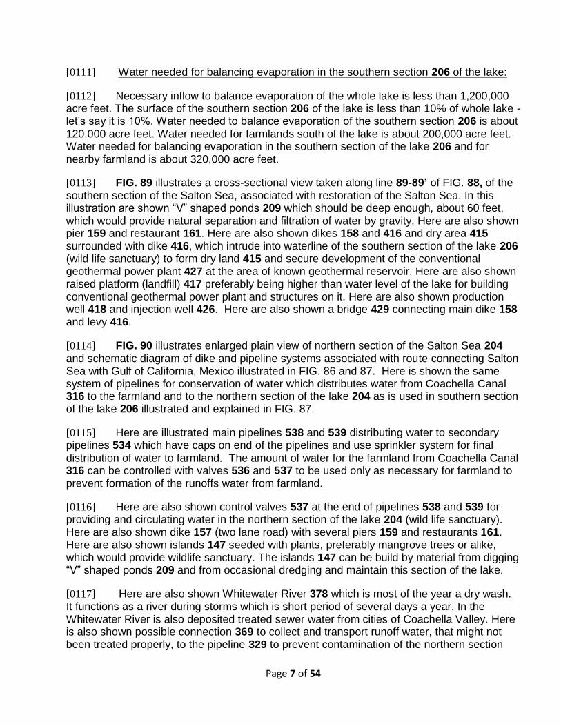
[0113] FIG. 89 illustrates a cross-sectional view taken along line 89-89’ of FIG. 88, of the southern section of the Salton Sea, associated with restoration of the Salton Sea. In this illustration are shown “V” shaped ponds 209 which should be deep enough, about 60 feet, which would provide natural separation and filtration of water by gravity. Here are also shown pier 159 and restaurant 161. Here are also shown dikes 158 and 416 and dry area 415 surrounded with dike 416, which intrude into waterline of the southern section of the lake 206 (wild life sanctuary) to form dry land 415 and secure development of the conventional geothermal power plant 427 at the area of known geothermal reservoir. Here are also shown raised platform (landfill) 417 preferably being higher than water level of the lake for building conventional geothermal power plant and structures on it. Here are also shown production well 418 and injection well 426. Here are also shown a bridge 429 connecting main dike 158 and levy 416.
[0114] FIG. 90 illustrates enlarged plain view of northern section of the Salton Sea 204 and schematic diagram of dike and pipeline systems associated with route connecting Salton Sea with Gulf of California, Mexico illustrated in FIG. 86 and 87. Here is shown the same system of pipelines for conservation of water which distributes water from Coachella Canal 316 to the farmland and to the northern section of the lake 204 as is used in southern section of the lake 206 illustrated and explained in FIG. 87.
[0115] Here are illustrated main pipelines 538 and 539 distributing water to secondary pipelines 534 which have caps on end of the pipelines and use sprinkler system for final distribution of water to farmland. The amount of water for the farmland from Coachella Canal 316 can be controlled with valves 536 and 537 to be used only as necessary for farmland to prevent formation of the runoffs water from farmland.
[0116] Here are also shown control valves 537 at the end of pipelines 538 and 539 for providing and circulating water in the northern section of the lake 204 (wild life sanctuary). Here are also shown dike 157 (two lane road) with several piers 159 and restaurants 161. Here are also shown islands 147 seeded with plants, preferably mangrove trees or alike, which would provide wildlife sanctuary. The islands 147 can be build by material from digging “V” shaped ponds 209 and from occasional dredging and maintain this section of the lake.
[0117] Here are also shown Whitewater River 378 which is most of the year a dry wash. It functions as a river during storms which is short period of several days a year. In the Whitewater River is also deposited treated sewer water from cities of Coachella Valley. Here is also shown possible connection 369 to collect and transport runoff water, that might not been treated properly, to the pipeline 329 to prevent contamination of the northern section

Page 8 of 54
204 and to be used in power plants 300 and subsequently to be used for replenishment of the depleting geothermal reservoirs.
[0118] Here are also shown a possible location for a Hotel Resort 540 with a section in the Salton Sea with the tower 550 to be built on manmade island 560 which contain a mechanism for generation of waves for surfing.
[0119] Water needed for balancing evaporation in the northern section 204 of the lake: Necessary inflow to balance evaporation of the whole lake is less than 1,200,000 acre-feet. The surface of the northern section 204 of the lake is less than 5% of the whole lake - let’s say is 5%. Water needed to balance evaporation of the southern section 204 is about 60,000 acre-feet. Water needed for farmlands north of the lake is about 100,000 acre-feet.
[0120] Water needed for balancing evaporation in the northern section of the lake 204 and for nearby farmland is about 160,000 acre-feet.
[0121] Water needed for balancing evaporation in the northern and southern sections of the lake and for nearby farmlands is about 480,000 acre-feet per year.
[0122] It means that we can functional lake with less than 480,000 acre feet per year from Colorado River, which means that this proposal is in harmony with restrictions from Quantification Settlement Agreement (QSA).
[0123] FIG. 91 illustrates enlarged plain view of a resort hotel 540 illustrated in FIG. 90. Here is shown preliminary design of the entrance to the hotel, parking spaces, swimming pool, and tennis courts.
[0124] FIG. 92 illustrates a cross-sectional plain view taken along line 92’- 92” of FIG. 93 of a tower 550 which contain mechanism for generating surfing waves also illustrated in FIG. 90. In FIGS. 92 and 93 is illustrated a concept of a wave generating facility 560 which extend into Salton Sea. The wave generating facility 560 consist of a tower 550 which contain mechanism for generating surfing waves; and wall segments 551 which surround surfing area.
[0125] The mechanism for generating surfing waves consist of the ax room 552 which is mounted in a recess 553 which is formed between three sides of structural walls 558 of tower 550. The ax room 552 is waterproof space suspended on cables 556 and securely engaged with vertical rails which are fixed to the three inner structural walls 558. There is access to the top of tower and ax room 552 by stairs 561and by elevators 562.
[0126] The back side of the ax room 552 is a vertical smooth surface. The ax room 552 consists of three waterproof segments: central segment 552; lower segment (reinforced container) 554; upper segment 555; and cables and winch 556 to hoist ax room 552. The central segment of the ax room 552 is furnished space for visitors having secured acrylic window in the front wall. The lower segment (reinforced container) 554 can be filled with water to adjust the weight of the ax 552 if needed.

Page 9 of 54
[0127] The upper segment 555 of the ax room 552 has a shape to smoothly increase volume and buoyancy as ax room penetrates water during fall. The ax room 552 provides space for visitors with secured acrylic windows so that visitors can view descent above and under water. The visitors are fastened and can experience weightless sensation for several seconds on the way down. As the ax room 552 plunges into the water the sharp edge of the lower segment provides smooth entry. The angled surface transfer energy of the fall into waves. As the ax room 552 enters water it pushes (expel) water out and forwards generating waves for surfers to ride on. [0128] As the ax room 522 sink the buoyancy increase and push the ax room 552 upward. The momentum of buoyancy is used to push ax room 522 up above water surface so that additional power for raising ax room is minimized. The ax room 552 is raised with a hoist (cable system) 556 to desired height and secured at that desired position with a controlled fastener (locks). The frequency of generating surfing wave can be scheduled for periods of 10-15 minutes. Here is also shown island 559 on which tower 550 is built. [0129] Important point of this concept is that two strong tourists’ attractions “weightlessness” and “surfing” are achieved minimizing operating expenses. Because of nice weather in the area, the presented concept would be the attraction for surfers for 12 months a year with a possibility of hosting surfing competition events. [0130] The wall segments 551 have pathway on top with safety rails and are connected with bridges 557 for visitors to reach tower by foot. The wall segments 551 are positioned so to concentrate waves in surfing area and to provide water circulation.
[0131] FIG. 93 illustrates a cross-sectional view of a wave generating tower 550 taken along line 93’- 93” of FIG. 92 also illustrated in FIG. 90. Here are shown all elements explained in FIG. 92. Here are also shown the light feature 563 on top of the tower 550 for light shows at night. Here are also shown deep reservoir 564 in which the ax room 552 plunges. Here is also shown, in dash-line, surfing waves 565 generated after the ax room 552 plunges into reservoir 564. It is realistic to expect that the tower 550, beside explained tourist attractions such as generating surf waves and weightlessness, might also be a symbolic “light hous” and be featured as such for the area.
[0132] FIG. 94 illustrates a cross-sectional view of a solar panel assembly 585 and its attachment system to the pipeline in accordance with the invention. Here is illustrated a solar panels assembly 585 installed on upper portion of the pipeline 400 for harnessing solar energy and for generation of electricity. In this presentation the pipeline 400 is used as a sample for explaining the system but the concept can be used in combination with any pipeline system.
[0133] FIG.100 illustrates a cross-sectional view of an alternative solar panel assembly 610 and its attachment system to the pipeline with lifting mechanism 612 taken along line 100’- 100” of FIG. 102. FIGS. 100 -104 illustrate a solar panels assembly 610 installed on the upper portion of the pipeline 400 to generate electricity. Similarly to solar panels assembly 600 presented in FIGS. 96 - 98 the assembly 610 also consists of the support structures 614
Page 10 of 54
slightly different to accommodate solar tracking (lifting) mechanism 612 and main beams 617 and 618; fastener assembly 588; solar panels 590; and solar tracking mechanism 601 to change position of the side panels to follow the sun and to maximize effectiveness of sunlight during the day.
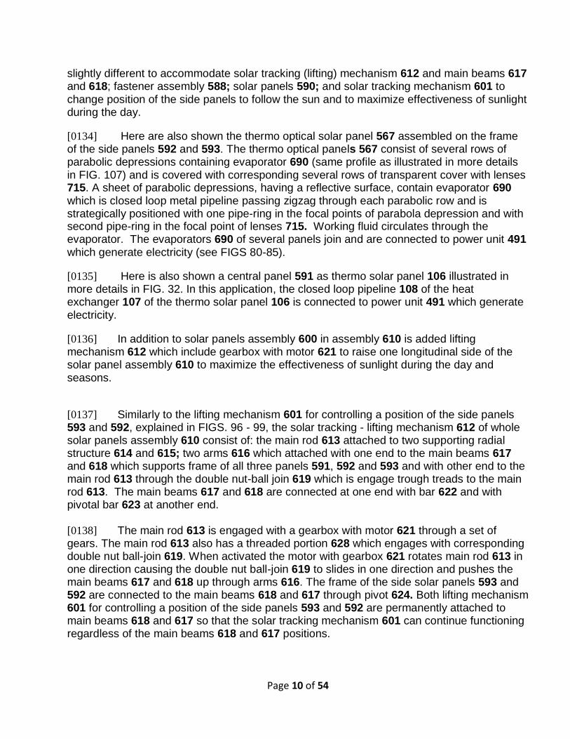
[0134] Here are also shown the thermo optical solar panel 567 assembled on the frame of the side panels 592 and 593. The thermo optical panels 567 consist of several rows of parabolic depressions containing evaporator 690 (same profile as illustrated in more details in FIG. 107) and is covered with corresponding several rows of transparent cover with lenses 715. A sheet of parabolic depressions, having a reflective surface, contain evaporator 690 which is closed loop metal pipeline passing zigzag through each parabolic row and is strategically positioned with one pipe-ring in the focal points of parabola depression and with second pipe-ring in the focal point of lenses 715. Working fluid circulates through the evaporator. The evaporators 690 of several panels join and are connected to power unit 491 which generate electricity (see FIGS 80-85).
[0135] Here is also shown a central panel 591 as thermo solar panel 106 illustrated in more details in FIG. 32. In this application, the closed loop pipeline 108 of the heat exchanger 107 of the thermo solar panel 106 is connected to power unit 491 which generate electricity.
[0136] In addition to solar panels assembly 600 in assembly 610 is added lifting mechanism 612 which include gearbox with motor 621 to raise one longitudinal side of the solar panel assembly 610 to maximize the effectiveness of sunlight during the day and seasons.
[0137] Similarly to the lifting mechanism 601 for controlling a position of the side panels 593 and 592, explained in FIGS. 96 - 99, the solar tracking - lifting mechanism 612 of whole solar panels assembly 610 consist of: the main rod 613 attached to two supporting radial structure 614 and 615; two arms 616 which attached with one end to the main beams 617 and 618 which supports frame of all three panels 591, 592 and 593 and with other end to the main rod 613 through the double nut-ball join 619 which is engage trough treads to the main rod 613. The main beams 617 and 618 are connected at one end with bar 622 and with pivotal bar 623 at another end. [0138] The main rod 613 is engaged with a gearbox with motor 621 through a set of gears. The main rod 613 also has a threaded portion 628 which engages with corresponding double nut ball-join 619. When activated the motor with gearbox 621 rotates main rod 613 in one direction causing the double nut ball-join 619 to slides in one direction and pushes the main beams 617 and 618 up through arms 616. The frame of the side solar panels 593 and 592 are connected to the main beams 618 and 617 through pivot 624. Both lifting mechanism 601 for controlling a position of the side panels 593 and 592 are permanently attached to main beams 618 and 617 so that the solar tracking mechanism 601 can continue functioning regardless of the main beams 618 and 617 positions.

Page 11 of 54
[0139] FIG. 101 illustrates a cross-sectional view of the solar panel assembly 610 and its attachment system to the pipeline with lifting mechanism 612, taken along line 101’- 101” of FIG. 102. Here is also illustrated rechargeable battery pack 625 to store energy to be used if and when needed. For example, stored energy can also be used to close extended panels in basic (default) closed position in emergency situations before storm on cloudy days when there is no sufficient sunlight or at night when there is no sunlight. Here is also shown box 626 with electronic for receiving and transmitting data.
[0140] FIG. 102 illustrates a longitudinal partial cross-sectional view of two adjacent solar panel assemblies 610 and its attachment system to the pipeline also illustrated in FIGS. 100 and 101. Here is also shown (in dash line) the main beams 617 and 618 of one solar panel assembly 610 in a raised position. Here is also shown a fire hydrant valve 545.
[0141] One of the strong benefits of the presented pipeline, besides its main purpose to transport seawater to desert, is that periodic segments of the pipeline can have side valve as fire hydrant 545 to which a hose can be attached to supply water for protecting the pipeline, inhabited areas, and forest in case of nearby wildfires. Such benefits can be presented as a strong factor in obtaining financial support (grant or long-term loan) from governments (state and federal) for implementation of the project.
[0142] FIG. 103 illustrates a side view of the solar panel assembly 610 and its attachment system to the pipeline 400 and its lifting mechanism 612 in a horizontal position. Most of the elements are illustrated and explained in more details in FIGS. 100-102. Here is also illustrated a condenser 660 installed under pipeline 400 to use coolness of the pipeline for condensation. The condenser 660 consist of bendt metal pipeline 662 and connectors 627 which connect closed loop line of the thermo optical solar system 567 and 700 which is installed nearby and is explained in FIGS. 106-112.
[0143] FIG. 104 illustrates a side view of a solar panel assembly 610 and its attachment system 588 to the pipeline 400 with its lifting mechanism 612 in raised position. Most of elements are illustrated and explained in more details in FIGS. 100-103. Here is also illustrated a condenser 661 installed around pipeline 400 to use coolness of the pipeline for condensation. The condenser 661 consist of bended metal pipeline 663 and connectors 627 which connect closed loop line of the thermo optical solar system 567 and 700 which is installed nearby and will be explained in FIGS. 106-112. Here is also shown an alternative condensed 664 for cooling battery pack 665 (illustrated in FIG. 106).
[0144] FIG. 105 illustrates a plain view of a solar panel assembly 610 and its attachment system 588 to the pipeline 400 with its lifting mechanism 612 with solar panels which include central panel 591 and side panels 567 in a horizontal position. All elements are illustrated and explained in FIGS. 100-104.
[0145] The benefits of this concept to combine solar panels with pipeline are: a) pipeline provides foundation and support for the solar panel assembly; b) If the pipeline already exists, then the “right of way” and service road can be easily negotiated with the owner. c) If the pipeline is a planed project then the “right of way” and necessary expenses can be

Page 12 of 54
shared; d) Presented pipeline system needs electricity to function and can be supplemented by electricity generated by solar panel installed on the pipeline; e) The length of pipeline would provide substantial footprint for generating electricity; e) Solar panels will provide shade for pipeline extending life of the pipeline; and f) The presented solar panel assembly system provides an easy assembly of the system on the pipeline without altering pipeline segments.
[0146] FIG. 106 illustrates a perspective view of a pipeline with solar panel assemblies 610 attached to the pipeline in combination with a line of alternative “thermo optical solar system” 700 aside pipeline. Here are illustrated two sets of the solar panel assemblies 610 installed on each segment of pipeline 400. The solar panel assembly 610 is illustrated and explained in more details in FIGS. 100-105. Here is also illustrated a line of “thermo optical solar system” 700 aside the pipeline 400 using the same right of way. The “thermo optical solar system” 700 consist of: a “thermo optical solar dish” 710 which contain lenses, mirrors and evaporator (illustrated in FIG. 107); power generating unit 491 (illustrated in FIGS. 79-85); condenser 660 using coolness of the pipeline 400; battery pack 665 for storing electricity generated during the day for use at night; and post 711.
[0147] Here is also shown thermally insulated closed loop line 720 transporting working fluid from evaporator in the “thermo optical solar dish” 710 to the power generating unit 491; Here is also shown thermally insulated closed loop line 721 transporting working fluid from the power generating unit 491 to condenser 660 and to the “thermo optical solar dish 710. Here is also shown thermally insulated closed loop line 722 connecting condenser 664 (see FIG. 104) for cooling battery pack 665.
[0148] Here is illustrated the “thermo optical solar system” 700 as an additional line to the solar panel assembly 610 to supplement needed energy for operation of the pipeline 400. Both systems - the “thermo optical solar system” 700 and the solar panel assembly 610 combined with photo voltaic (PV) central panel 591 and with thermo optical solar side panels 567 can be used separately. For example the “thermo optical solar dish” 710 can be attached to the segments of the pipeline directly through a support structure 733 with fastener 734 and surrounding belt 611 (see FIGS. 113). The “thermo optical solar dish” 710 can be used for residential applications for generating electricity and worm water. In residential application the condenser 660 can be coupled into heater (boiler) for generating worm water. Alternatively, the condenser 660 can be placed underground or cooled conventional way with fan.
[0149] FIG. 107 illustrates a cross-sectional view of a “thermo optical solar dish” 710 taken along line 107’- 107” of FIG. 108, also illustrated in FIG. 106. The “thermo optical solar dish” 710 consist of: tubular frame 701 consisting of peripheral ring 702 and inner ring 703 which are connected with crossbars 704 formed in shape to support main dish 705 which has a shape of lower half of doughnuts. The main dish 705 has a circular peripheral indentation in profile shape of a parabola and opening 707 in the middle. The inside of main dish 705 is coated with a reflective material (mirror). The main dish 705 accommodates evaporator 690 which has at least one pipe-ring (evaporator) positioned in the focus of the parabola 708. The main dish 705 is covered with corresponding cover dish 706 made of transparent material such as glass, acrylic, or plastic. The cover dish 706 has a shape of upper half of

Page 13 of 54
doughnuts having circular peripheral concave indentation corresponding to the main dish 705. It also covers central opening 707 with separate concave indentation 714. The cover dish 706 inside peripheral concave indentation contains continues circular lens 715 for focusing sunrays on at least one pipe-ring 717 of the evaporator 690 positioned in the focus of the lens 709. The evaporator 690 has at least two pipe-rings of which first one 716 is positioned in the focus of parabola 708 of the main dish 705 and second one 717 is positioned in the focus of the lens 709 of the cover dish 706.
[0150] Here is also illustrated cross bar 704 which is pivotally engaged with a fork 718 which is connected to the branch 719 of the post 711 (see Fig. 106). There is also a back dish 722 which encapsulate main dish 705 and connect it to the pivotal arms 723 and 724 through fastener 725. Here is also illustrated a solar tracking mechanism (servo motor) 713 for rotating dish 710 around axis of the cross bar 704 when tracking latitude of the sun. Here is also illustrated a box 726 with electronics for programming and transmitting data for tracking the sun. The fork 718 can have motor for rotating each dish 710 when tracking longitude of the sun. The post 711 (see Fig. 106) have solar tracking mechanism (servo motor) 712 for rotating several branches with “thermo optical solar dish” 710 when tracking longitude of the sun.
[0151] When sunrays pass through transparent cover dish 706 reflects from reflective surface of the main dish 705 into focus point of the parabola 708 where first pipe-ring 716 of the evaporator 690 is positioned. In the focus point 708 high temperature is generated and heats working fluid passing through pipe-rings 716 of the evaporator 690.
[0152] When sunrays pass through lens 715 of transparent cover dish 706 focuses into its focus point 709 where second pipe-ring 717 of the evaporator 690 is positioned. In focus point 709 high temperature is generated and heats working fluid passing through pipe-rings 717 of the evaporator 690.
[0153] The pipe-rings of the evaporator 690 passes through a coil 730 in the central opening 707 of the main dish 705 where the evaporator is still heated through lens 727 of central part of the transparent cover dish 714 on the way to and from the power unit 491 where electricity is generated (see Fig. 106). Here is also illustrated pivotal plate 728 which connect pivotal arm724 with fork 718 and branch 719 of the post 711. Here is also illustrated pivotal plate 729 which connect pivotal arm723 with fastener 725 and back dish 722. The pivotal arms 724 and 723 are engaged with pivot 731. Here is also shown thermally insulated line 720 of the closed-loop system which connects evaporator 690 and power unit 491 which generate electricity.
[0154] Although the “thermo optical solar system” 700 presented here has not been tested yet, it is realistic to expect that the “thermo optical solar system” can generate many-fold electricity per unit surface than photovoltaic system because power density is substantially higher.
[0155] The thermo optical solar system is presented here for this particular application of the pipeline system, but it is not limited to pipeline system it can be used in residential applications.

Page 14 of 54
[0156] Presented thermo optical solar system can be also minimized to micro level and can be used in many application covering many surfaces for example surface of electric airplane, electric car, roofs and walls of buildings, etc., to harness solar energy more efficiently from surfaces exposed to sunrays and to transfer necessary heat to binary power unit, using piston system, for generation of electricity. The power unit can be positioned in an appropriate location relative to and in balance to the surfaces exposed to sunrays equipped with the micro thermo optical solar system. Several modular surfaces equipped with the micro thermo optical solar system can join one binary power unit. The micro thermo optical solar system can be produced by 3D printing.
[0157] FIG. 108 illustrates a plain view of a “thermo optical solar dish”. Most of elements and its function are explained in FIG. 107.
[0158] FIG. 109 illustrates a side view of a “thermo optical solar dish”. Most of the elements and its function are explained in FIG. 107.
[0159] FIG. 110 illustrates a schematic diagram of the flow of the working fluid in the evaporator 790 of “thermo optical solar dish” 710 illustrated in FIGS. 106-109. Here are shown pipe-rings 717 which is positioned at the focal point of the circular lens715 and pipe-rings 716 which is positioned at the focal point of the parabola of the main dish 705. Here is also shown coil 730 positioned at opening 707 of the main dish 705.
[0160] FIG. 111 illustrates an alternative pattern of the evaporator 690 in the “thermo optical solar dish” 710. Here are illustrated pipe-rings 717 which are positioned in the focal point of the circular lens715 and pipe-rings 716 which are positioned at focal point of the parabola of the main dish 705. Here are also shown multi pipe-rings 732 parts of closed loop system of the evaporator 690 positioned between pipe-rings 717 and 716. Here are also shown clamp/fasteners 735 which secure pipe-rings 717, 716 and 732.
[0161] FIG. 112 illustrates an alternative pattern of the evaporator 690 in the “thermo optical solar dish” 710. Here is illustrated an alternative pattern 688 of the evaporator 690.
[0162] FIG. 113 illustrates a cross-sectional view of the “thermo optical solar dish” 710, which is essential element of the thermo optical solar system 700, assembled on the pipeline 400. Here are shown elements explained in FIGS. 106-112. In addition, here is shown a support structure 733 with fastener 734 and surrounding belt 611 for securing thermo optical solar assembly 710 on the pipeline 400. Here are also shown attachments 215 and 216 which connect evaporator 690 inside main dish 705 to the power unit 490 nearby (see FIG. 80). Here is also shown an electro motor (servo) 712 for rotating assembly 710 for longitudinal traction of the sun during the day.
[0163] Preliminary Cost Estimate for Phase I & II
[0164] This proposal is a preliminary design explaining the feasibility of the concept. The second stage would require collaboration with potential contractors and would contain more details, including more detailed cost estimate, which would follow with the final production design.

Page 15 of 54
The range of cost today of installed pressure pipe of 48-inch diameter in various terrains is about $600 – $1,000 per linear foot. Here is used most conservative option $1,000 per linear foot. A mile = 5,280’ x $1,000 = $5,280,000;
Distance about 160 miles.
$5,280,000 x 400 miles (80 miles uphill x 5 pipelines) = $2,112,000,000.
$5,280,000 x 80 miles (80 miles downhill x 1 pipeline) = $422,400,000.
Connecting the Salton Sea with the Pacific Ocean (San Diego area) distance about 160 miles - 80 miles uphill (5 pipelines) + 80 miles downhill (1 pipeline ) it ends up to about $2,534,400,000.
Because of mountain terrain + development of a new product + several pumping stations + several tanks on uphill route + several “split and join” power plants + final “delta” power plant on the final route + adding several freeway underpasses, right-of-way permits - the cost might increase 40% ending to about $3.5 billion.
Preliminary cost estimate for the solar panel assembly (thermo solar systems and the thermo optical solar system) is about $200 million. Preliminary cost estimate for two main dikes (about 15 miles), separating the Salton Sea and optional several secondary dikes (another 15 miles), including treatment plants, could cost about $3 billion, which would add up (I & II phase) to about $8.5 billion. Preliminary cost estimate for three Power Plants (final development of the system, including drilling system, and production of one at each sector) might come to about $1 billion.
Using pipeline system for farmland as a foundation for the solar system in southern and northern areas of the lake is an additional option for generating electricity and can be financed separately by the private sector or the IID or the CVWD.
Preliminary Cost Estimate for Phase III & IV
Proposed Geothermal Power Plant(s) - the “Scientific Geothermal Technology” consists of 24 well-bores and with many projected power plants (in 100s) drilling is most expensive and most important part, therefore we need to implement a new system for drilling faster, deeper and wider wellbores. The cost for 60” diameter wellbore 8,000 feet deep might cost about $4 M; 24 wellbore x $4M = $96,000,000;
Page 16 of 54
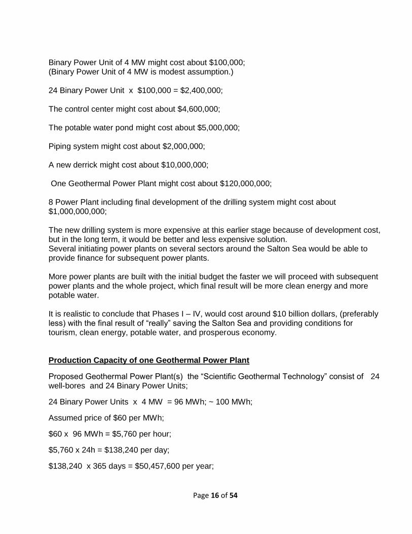
Binary Power Unit of 4 MW might cost about $100,000; (Binary Power Unit of 4 MW is modest assumption.) 24 Binary Power Unit x $100,000 = $2,400,000; The control center might cost about $4,600,000; The potable water pond might cost about $5,000,000; Piping system might cost about $2,000,000; A new derrick might cost about $10,000,000; One Geothermal Power Plant might cost about $120,000,000; 8 Power Plant including final development of the drilling system might cost about $1,000,000,000; The new drilling system is more expensive at this earlier stage because of development cost, but in the long term, it would be better and less expensive solution. Several initiating power plants on several sectors around the Salton Sea would be able to provide finance for subsequent power plants. More power plants are built with the initial budget the faster we will proceed with subsequent power plants and the whole project, which final result will be more clean energy and more potable water. It is realistic to conclude that Phases I – IV, would cost around $10 billion dollars, (preferably less) with the final result of “really” saving the Salton Sea and providing conditions for tourism, clean energy, potable water, and prosperous economy. Production Capacity of one Geothermal Power Plant
Proposed Geothermal Power Plant(s) the “Scientific Geothermal Technology” consist of 24 well-bores and 24 Binary Power Units;
24 Binary Power Units x 4 MW = 96 MWh; ~ 100 MWh;
Assumed price of $60 per MWh;
$60 x 96 MWh = $5,760 per hour;
$5,760 x 24h = $138,240 per day;
$138,240 x 365 days = $50,457,600 per year;

Page 17 of 54
Technology Summary:
There is an infinite source of energy under our feet, whether it is a few miles underground or on the ground surface in locations such as Hawaii. The question was, until now, how to harness it expediently and efficiently without polluting the environment? Presented methodology capitalizes on our planets natural internal heat.
The essence of the “Scientific Geothermal Technology” is transferring heat from heat sources to the power units with completely closed loop systems.
The "Self Contained In-Ground Geothermal Generator" (SCI-GGG) system uses several completely closed loop systems and generates electricity down at the heat source and transmits it up to the ground level by means of electrical cables.
The SCI-GGG apparatus consists of: a boiler; a turbine; a converter; a generator; a condenser distributor; and a condenser that is arranged to function in confined spaces such as in a well bore. The SCI-GGGG absorbs heat from the source of heat (hot rocks and/or geothermal reservoir) and generates electricity at the heat source which is transmitted by cable to the ground surface to electrical grids for use in houses and industry.
In the process of cooling the engine compartments with a separate closed loop system which is the “Self Contained In-Ground Heat Exchanger” (SCI-GHE system) additional electricity is generated on the ground surface.
The "Self Contained In-Ground Heat Exchanger" (SCI-GHE) system is an integral part of the SCI-GGG system and can function independently. The system consists of a closed loop thermally insulated line with 2 coiled pipes (heat exchangers) and a few in-line- pumps. The first heat exchanger is lowered to the bottom of the wellbore at the heat source and the second heat exchanger is coupled into a binary power unit on the ground surface which produces electricity by using the Organic Rankine Cycle (ORC). Electricity is then transmitted through an electric grid.
Although the (SCI-GHES) system has a higher production capacity at this project at this early stage priority is given to the SCI-GHE system because of its less expensive production and easier maintenance.
The presented proposal also includes a method for harnessing geothermal energy for generation of electricity by using complete closed-loop heat exchange systems combined with onboard drilling apparatus.
The In-Line-Pump is an integral part of both SCI-GGG and SCI-GHE systems, circulating fluids through closed loop systems.
The In-Line-Pump is an electromotor cylindrical shape and is inserted as a repetitive segment in the pipeline. It has a hollow cylinder as a shaft of the rotor with continues spiral blades inside hollow shaft. It yields a maximum flow rate with limited diameter.

Page 18 of 54
Alternatively, the In-Line-Pump can be inserted as a repetitive segment of a riser pipe for pumping fluids up to the ground surface from reservoirs in which geo-pressure is low. Also, the In-Line-Pump can be used as a repetitive segment in cross-country pipeline for transporting oil, water, etc. In downhill route, it functions as a generator and generates electricity, which can be used to supplement in-line-pumps in horizontal and uphill route.
Methodology for Drilling Faster, Deeper, and Wider WellBore
Contemporary drilling system has limitations how wide and deep wellbore can be drilled. Mud is injected through the pipe and through several orifices at the drill bit. Mud circulates up between pipe and wall of the wellbore providing a necessary stream for cutting to be excavated. By increasing the size of the drill bit (wellbore) and/or by increasing the depth of the wellbore it requires a substantial increase of pressure inside the pipe to form a corresponding stream for excavation of cuttings;
Presented system for drilling faster, deeper and wider wellbore consist of motorized drill head; separate excavation line; separate fluid delivery line; and separate closed loop cooling line engaged with Binary Power Unit on the ground surface.
The Binary Power Unit consists of: a Boiler; a Turbine; a Condenser; and a Generator.
The boiler is coupled with coil (Heat Exchanger) from a separate closed loop engine cooling line circulating fluid from motorized drill head. A generator of the binary unit generates electricity to supplement power for the motorized drill head. Presented drilling apparatus has retractable bits on the motorized drill head. Also, the casing of the wellbore can be built during the drilling process.
The diameter of the excavation line and rate of flow of mud and cuttings through it and the diameter of the fluid delivery line and rate of fluid flow through it are in balance requiring only limited fluid column at the bottom of the wellbore.
Fluid column may exist through the whole wellbore to sustain the wellbore during the drilling process, but not for excavation purpose. The excavation process continues regardless of the diameter of the drill head (wellbore); therefore this method eliminates well-known drilling limitations relative to the depth and diameter of the wellbore.
The Photo-Voltaic (PV) panel assembly system for pipelines: The Photo-Voltaic (PV) panel assembly system is designed to use pipeline as foundation and to share proportionally expenses for the “Right of Way” and the profit. The Photo-Voltaic (PV) panel assembly uses conventional PV panels with a special fastening device for the assembly to be attached to the segments of the pipeline. It also has sun-tracking mechanism. Although PV solar panels are not very efficient energy suppliers the pipeline provides a substantial surface that otherwise would need to be selected, leased or purchased. The Thermo Solar system (TS): The Thermo Solar system (TS) presented here use the pipeline as a foundation and to share proportionally expenses for the “Right of Way” and the profit.

Page 19 of 54
The Thermo-Optical Solar system (TOS): The Thermo-Optical solar system (TOS) presented here use the pipeline as a foundation and to share proportionally expenses for the “Right of Way” and the profit – consist of a panel or dish with special configuration; evaporator with working fluid; power unit and condenser. The dish has a parabolic cavity with a reflective surface to reflect sunrays into the focus of the parabolic cavity where part of the evaporator is positioned. This system also uses lenses to focus sunrays in an additional part of the evaporator. The working fluid circulates through the evaporator which is connected to the power unit which generates electricity. In this presentation, the Thermo-Optical solar system is engaged with the pipeline system by sharing the “right of way” of the pipeline and using colder temperature of the pipeline for cooling the condensers. Presented “thermo optical solar system” has not been tested yet, but it is realistic to expect that it can generate multi-fold electricity per unite surface than photovoltaic system because power density is substantially higher. Desalinization System Desalinization system consists of the "Self Contained In-Ground Heat Exchanger" (SCI-GHE) system; distiller/evaporator; and a desalination building. The first heat exchanger coil of the SCI-GHE) system is placed at the source of heat and the second heat exchanger coil is coupled into distiller for heating it, and wherein the distiller is filled with salty water and used steam for operating a power unit (turbine and/or pistons) for generation of electricity. Exhausted steam is condensed and collected as potable water. The remaining salty water from distiller is transported through a piping system into a desalination building and into containers for heating and evaporation. Containers with salty water are heated with a piping system from the first closed loop system of the SCI-GHE system and partially from heat from the condenser. The desalination building is a closed structure with a greenhouse effect and comprises: containers with salty water and its delivery system; a heating system positioned under containers; a condenser positioned on upper portion of the building with its cooling system; a collection of freshwater and its distribution out of building; and collection and distribution of collected salt. The desalination building can be used for extraction of minerals and lithium.
Transformational Merit:
Regarding geothermal power plants:
Presently, wells are drilled into the geothermal reservoirs to bring the hot water to the surface. At geothermal power plants, this hot water is piped to the surface. Then, after removing silica steam is used to spin turbines creating mechanical energy. The shaft from the turbines to the generator converts mechanical energy into electrical energy. The used geothermal water is then returned down through injection well into the reservoir to be reheated, to maintain pressure, and to sustain the reservoir.
There are three kinds of geothermal power plants. The kind is built depends on the temperatures and pressures of a reservoir.

Page 20 of 54
There is also an experimental Enhanced Geothermal System. In order to function properly Enhanced Geothermal Systems (EGS) needs three crucial factors: Horizontal rock formation, Permeability of the rocks, Heat and a substantial amount of Water. Those are serious limitations. The EGS is based on exploring certain locations (nests) and injecting water in those locations until heat from hot rocks is depleted (about 4-5 years) and then moving to another (preferably nearby) location and then repeating the process and after 3-5 years returning to previous location which would by that time replenish the heat generated from radioactive decay and internal heat. I call it “horizontal approach” since geothermal water between injection well and production well travels typically horizontally.
The presented proposal implements the “Scientific Geothermal Technology”. Embodiments of the system of the present invention promote a progressive “vertical approach” to reach and utilize heat from hot rocks or another heated surrounding environment rather than the horizontal approach used in Enhanced Geothermal System (“EGS”).
Because the "Self Contained In-Ground Geothermal Generator" (SCI-GGG system) and “Self-Contained In-Ground Heat Exchanger” (SCI-GHE system) uses a completely closed loop systems, the permeability of the rocks, horizontal rock formations and substantial amount of underground water is of lesser importance, because the systems operate in a “vertical approach” and the heat exchanging surface of the wellbore can be increased by drilling deeper wellbore. When cooling of surrounding rocks eventually occurs, it would only be necessary to circulate the geothermal fluid in a wellbore around the first heat exchanger with an in-line-pump secured below the first heat exchanger. Having an additional dept of the wellbore, let’s say a half mile below heat exchanger, with a diameter of 5’-6’ the heat exchanging surface of the wellbore will be sufficient and heat flux should not be an issue
especially if a temperature of the surrounding rocks is over 200⁰ C.
If cooling of the rocks becomes an issue again we can turn on drilling apparatus, which is a permanent part of the heat exchange apparatus, and drill an additional distance, let’s say, a few hundred yards, to reach hot rocks and lower the apparatus at the new depth. The extended depth will result in hotter rock formations and higher heat flux. Eventually, a point will be reached where heat extraction from rocks and heat replenishment to the rocks from the heat generated by radioactive decay and internal heat will be in balance - equilibrium.
The power plant comprising an array of wellbores having an extendable length for periodically extending the length of each wellbore; multiple power units corresponding to each wellbore, wherein each power unit includes a heat exchanger, each heat exchanger located within one wellbore of the array of wellbores, wherein the power generated corresponds to the number of wellbores and heat exchangers. The system of power units is a modular system capable of easy adjustments and reproduction.
Regarding source for Lithium production:
Lithium – a soft silver-white element that is the lightest metal known - is in high demand because is used for the production of batteries, ceramic, aluminum, and alloys.
In Chile and Bolivia the brines that are used to produce lithium (and other alkali metals) are supersaturated and sitting on the surface in playas (salt pans). That makes them much more

Page 21 of 54
economical than saline groundwater. Bolivia has huge reserves that the government is planning to put into production in cooperation with foreign companies. Seawater is a very poor source because the lithium concentration of seawater is about 0.2 parts per million (e.g., recovery of 1 ton of lithium requires treating 5 million tons of water).
There are several known methods for production of lithium. The SRI International company is tasked with two-year mission by the Energy Department’s Geothermal Technologies Office – focusing on advances in lithium recovery from geothermal brines using ion-imprinted polymers. To support this goal, SRI’s immediate technical objective is to further advance the performance and efficiency of ion-imprinted polymers to achieve optimal lithium separation rates exceeding 95%.
Earlier tests have already demonstrated that the polymer-based approach can yield a retrievable rate of more than 90%, so the Energy Department is confident that SRI can further refine the process and push that rate over 95%. Curtsey to the article at the link below.
http://www.desertsun.com/story/tech/science/energy/2017/02/10/salton-sea-geothermal-plant-would-use-lithium-tech-caught-teslas-eye/97743092/.
The lithium can be produced from saturated brine, but the processes of reaching saturated brine require extra efforts, processes, and energy which increases production cost.
Presented proposal for the restoration of the Salton Sea, which can be implemented with minor modifications in many similar locations worldwide provide an inexpensive and renewable source of the saturated brine for whichever process for extraction of lithium and other alkaline metals and minerals are going to be used.
In the presented proposal a distiller/boiler is filled with salty water from the nearby sources. After at least half of salty water from a boiler evaporates and after passing through turbine/pistons of the power unit (plant) as exhausted steam, it is condensed as potable water. The remaining, now higher salinity brine, from the boiler, is deposited (stored) into the wellbore to provide a medium for heat conduction from hot rocks to the first heat exchanger in the wellbore. After a certain period of time at the bottom of the wellbore will be accumulated highly saturated brine which frequently needs to be pumped out through the excavation line to the processing building for extraction of lithium and other alkaline metals and minerals.
The processing building for extraction of lithium and other alkaline metals and minerals is designed so to induce evaporation and collect potable water without using additional electricity which also contributes to lower production cost.
Regarding drilling system:
Contemporary drilling system has serious limitations how wide and deep wellbore can be drilled. Mud is injected through the pipe and through several orifices at drill bit and circulates up between pipe and wall of the wellbore providing a necessary stream for cutting to be excavated. By increasing the size of the drill bit (wellbore) and/or by increasing the depth of the wellbore it requires a tremendous increase of pressure inside the pipe to form a

Page 22 of 54
corresponding stream up for cuttings to be excavated. Also, wellbore has gradually smaller diameter with each subsequent section because of the casing.
The presented proposal provides a solution for drilling deeper and wider wellbores with the constant diameter. Presented system for drilling faster, deeper and wider wellbore consist of motorized drill head; separate excavation line; separate fluid delivery line; and separate closed loop cooling line engaged with Binary Power Unit on the ground surface. Presented drilling apparatus has retractable bits on the motorized drill head. Also, the casing of the wellbore can be built during the drilling process. The apparatus consists of the elevator sliding over the drilling/excavation/heat exchange apparatus delivering and installing casing sheets and concrete.
Regarding pumping stations:
Contemporary pumping stations and hydroelectric power plants are expensive and have restrictions on a location, capacity, and access.
The presented proposal provides a solution for an efficient water transfer.
Downhill routes of the pipeline can be built using several cascades with “split and join” hydropower plants to avoid buildup of extreme pressure in the pipeline especially in the last section of the final downhill route. By using several cascades with several “split and join” hydropower stations this system will harness kinetic energy and minimize loses. Also, final downhill route of the pipeline has “delta” system hydropower plant to increase efficiency in harnessing kinetic energy by splitting the flow of water after primary in-line-generators. The main in-line-generators are the first generators after the cascade drop with less exposed spiral blades inside the shaft/pipe harnessing energy and allowing fluid flow to continue to the subsequent smaller pipes with slightly lesser speed. After exiting the main in-line-generators the flow is split into two subsequent smaller branches with smaller in-line-generators which have more exposed spiral blades inside shaft/pipe. By splitting fluid flow into smaller branches with lesser fluid flow speed in each subsequent branch, therefore, increasing efficiency of harnessing kinetic energy and at the same time allowing the same mass of water to leave pipeline and enter the lake as the amount of water entering pipeline from the Ocean. The presented solution increased efficiency of harnessing kinetic energy and minimizes loss of energy that would occur due to resistance in the pipeline during 80 miles long downhill route.
In order to accommodate the same amount of water exiting downhill pipeline the same amount of water needs to enter the pipeline at the uphill route. That is achieved by having several pipelines comprising the uphill route with lesser fluid speed through them.
Importing seawater:
In several decades had been mentioned several proposal by different authors about importing water from the Ocean but they all failed to address: salinity balance of the lake – proposing expensive processes such as reverse osmosis and distillers which require substantial amount of electricity, maintenance of filters, etc.; not addressing continuation of pollution from nearby farmland; practicality of the projects - implementing canals, tunnels, etc.; and extreme cost which could not be repaid.

Page 23 of 54
The presented proposal is quite different - it incorporates in final comprehensive design, several patented technologies – that have not been accessible to the authors of previous proposals. The presented proposal has an architectural element which harmoniously incorporates several patented technologies in a functional self-sustaining organism.
NOTE: Alternatively - If forever reason construction of the pipeline for importing seawater into the Salton Sea is delayed, production of the Power Plants can continue with minor modification in design. For example: The boiler of power units can operate with working fluids such as isobutene, isopentan, etc., instead off with salty water from the lake. In such case, the power plant would produce electricity, but would not produce as byproduct potable water and would not produce saturated brine for the production of lithium. Later on, as pipeline is completed the power plants could be modified to use seawater as originally designed.
In the meantime, during construction of the pipeline, as an alternative, the power plant could continue its operation using salty water from the bottom of the lake to generate electricity and saturated brine for the production of lithium. Produced potable water can be bottled or returned into the lake to sustain depleting lake and to reduce its salinity.
Since importing seawater from the Ocean, especially route over the mountain, require a substantial amount of electric power one or two power plants, out of many proposed, can be designated for production of electricity to be used for importing seawater from the Ocean. Cooperation of the pipeline system with the solar panel system will generate enough energy for operation of the pipeline and for selling rest to the grid. Importing seawater from the Ocean is a fundamental phase of this comprehensive project on which other phases depend. Illustrations are provided in PowerPoint Presentation slides. There are several possible routes for importing seawater from the Ocean to the Salton Sea.
Preliminary analyzes of several route options:
Rough calculations for several routes for importing seawater to the Salton Sea
PE (Potential Energy) = M G H
==> Mass x Gravitation x Height (in meters)
Water that falls through pipe or exit under pressure from pipe (turbine)
KE (Kinetic energy) = 1/2 x M x V2
M = mass V = velocity of the water at the nozzle (exit)
Difference between surface of the Ocean and surface of the Salton Sea is - 230 feet (about 70 meters).

Page 24 of 54
Route # 1 - Importing seawater from the Gulf of California – corridor: San Felipe - Mexicali, Mexico, - Salton Sea. Pipeline distance is about 150 miles.
Free Fall:
S = ½ g x t²;
S = Vertical distance;
g = gravity = 9.81;
t = time
Free Fall values at 70 meters drop:
S = ½ g x t²
70 = ½ x 9.81 x t²
t² = 140 / 9.81 = 14.27
t = √14.27 = 3.77 seconds
Speed of water at nozzle at the bottom of the vertical fall at 70 meters:
V = g x t
V = 9.81 x 3.77 = 37.05 meters per second (41.01 y/s)
Kinetic Energy
For 70 meter drop from top of the hill to the surface of the lake
The surface of the lake is 70 meters below ocean level.
Speed of the water at the surface of lake or at the turbine is 37.05 m/s (41.01 y/s)
Ek = ½ M x V²
Ek = Kinetic Energy
M = Mass
M = Ek x 2/ V²
M = 1.16 x 37.05 = 42.98 => 42.98 x (994kg = weight of water at 100 ⁰F) = 42,720kg
(42,720 kg is the volume / mass of water per second).
Ek = ½ M x V² = ½ x 42,720 kg x (37.05 x 37.05 ) => ½ x 42,720 kg x 1,372.7
=> ½ 58,641,744 = 29,320,872 MWs in period of one hour it is 29.3 MWh
Efficiency factor usually used is 15% loss => 29.3 MWh x 0.85 = 24.9 MWh

Page 25 of 54
At this early stage without final testing of the new system, it is realistic to expect that by using “delta” hydropower plant which harness energy after main turbine using mass and speed of fluid (no gravity) can be harnessed an additional 10% of energy which is about 2.4 MWh which end up to about 27.3 MWh.
Presented “thermo optical solar system” has not been tested yet, but it is realistic to expect that it can generate multi-fold electricity per unite surface than photovoltaic system because power density is substantially higher.
Photo Voltaic PV panels on 160 miles (length of pipeline) = 141.137 acres of panels ==>. 141.137 acres (of panels) x 1.5 MWh = 211.75968 MWh.
Although ten-fold ratio would be a more realistic ratio, here will be calculated only five-fold ratio.
The Thermo Optical Solar (TOS) System installed on pipeline Route #1 can generate 1,058.79 MWh.
Revenue generated from the Thermo Optical Solar (TOS) system installed on pipeline Route #1:
1,058.79 MWh x $60 = $63,527.4 per hour;
$ 63,527.4 x 6 hours = $381,164.4 per day;
$381,164.4 x 300 days = $114,349,320 per year.
Revenue generated from the Thermo Optical Solar (TOS) System installed on pipeline Route #1 would be at least $114,349,320 per year.
Revenue generated from the “Delta” hydro power plant :
27.3 MWh x $60 = $1,638 per hour;
$1,638 x 24 hours = $39,312 per day;
$39,312 x 350 = $13,759,200 per year.
Revenue generated from the “Delta” hydro power plant would be $13,759,200 per year.
Revenue total: $128,108,520 per year.
It is realistic to expect that starting with 5 pipelines with diameter of 48” and speed of seawater 7.4 m/s (8.2 y/s) at Gulf of California (near San Felipe) and then gradually reducing number of pipelines through several sections of 150 miles distance to 5, 3, and 1 pipeline (50 miles x 5 pipelines + 50 miles x 3 pipelines + 50 miles 1 pipeline) in a few weeks the speed of seawater through pipeline will be stabilized and will continue without using initial in-line-pump at the entrance of the pipeline.

Page 26 of 54
Diameter of pipe is 48”
= 3.14 x (2x2) = 12.56 f² 12.56 f² / 9 = 1.39 y² = 1.16 m²
1.39 y² x 41.0 y per s = 57.00 y³ x (31,536,000 seconds in a year) = 1,797,674,900 y³ = 1,114,261 acre foot per year. This is volume of seawater entering the lake through one pipe with diameter 48” at speed of 41.0 y/s (yard per second).
V = velocity => 7.4 m/s = 8.2 y/s is the speed that is needed to pump water from the ocean through 5 pipelines of 48” diameter to balance for evaporation at the lake’s surface which is about 1,100,000 acre foot per year.
The volume / mass of water (42,720 kg) per second exiting the main in-line-generator at speed of 37 mps (41 y/s) and after “delta” hydropower plant entering the Salton Sea is the same mass of water (42,720 kg) per second entering 5 pipelines in Gulf of Mexico at speed of 7.4 mps (8.2yps).
Production Capacity of the Hydropower Plant:
Assumed price of $60 per MWh;
$60 x 27.3 MWh = $1,638 per hour;
$1,638 x 24h = $39,312 per day;
$39,312 x 365 days = $14,348,880 per year;
The Route # 1 would be the least expensive because of suitable topography of the terrain – about 10 meters elevation to overcome, but it deals with the “Other Country issue” which is a big issue.
Route # 2 - Importing seawater from the Ocean – corridor: Oceanside – Temecula - San Jacinto - (existing tunnel) – Cabazon - Salton Sea. Elevation to overcome is 1,600‘ (488 m).
Pipeline distance is about 160 (150) miles.
Downhill routes of the pipeline can be built using several cascades with “split and join” hydropower plants to avoid buildup of extreme pressure in the pipeline especially in the last section of the final downhill route. By using several cascades with several “split and join” and “delta” hydropower stations this system can harness more kinetic energy and minimize loses.
Free Fall values at 488 meters + (70 meters Ocean to Lake difference) = 558 meters
On this route can be used 2 cascades each with 279 m drop and 6 uphill pumping stations.
Free Fall:
S = ½ g x t² ;

Page 27 of 54
S = Vertical distance ;
g = gravity = 9.81 ;
t = time
Free Fall values at 279 meters
S = ½ g x t²
279 = ½ x 9.81 x t²
t² = 558 / 9.81 = 56.88
t = √56.88 = 7.54 seconds
Speed of water at nozzle at the bottom of the vertical fall at 279 meters:
V = g x t
V = 9.81 x 7.54 = 73.98 m/s = (80.9 y/s)
Kinetic Energy
For 279 m drop (first cascade) to the first in-line-turbine /generator.
Speed of the water at the exit of first in-line-turbine /generator is 73.98 m/s = (80.9 y/s)
Ek = ½ M x V²
Ek = Kinetic Energy
M = Mass
M = Ek x 2/ V²
M = 1.16 x 73.98 m/s = 85.81 m³ => 85.81 x (994kg = weight of water at 100 ⁰F) =
85,302 kg
(85,302 kg is the volume / mass of water per second).
Ek = ½ M x V² = ½ x 85,302 kg x (73.98 m/s x 73.98 m/s) => ½ x 85,302 kg x 5,473
=> ½ 466,857,840 = 233,428,920 MWs in period of one hour it is 233.43 MWh
Efficiency factor usually used is 15% loss => 233.43 MWh x 0.85 = 198.41 MWh
Two such cascade drops adds to 198.41 MWh x 2 (cascade drops) = 396.82 MWh
At this early stage without final testing of the new system, I believe that by using “split and join” hydropower plants and “delta” hydropower plant which harness energy after fluid leaves main turbine using mass and speed of fluid (no gravity) can be harnessed additional 10% of energy which is about 39.6 MWh. In this case, it ends up to about 436.4 MWh .

Page 28 of 54
The energy needed to transport the same amount of water through uphill pipeline section(s) which in this case (Route # 2) is 1,600‘ (488 m).
EP = M x g x h = 85,302 kg x 9.81 x 488 m = 408,364,550 MWs in an hour it is 408.3 MWh
Efficiency factor could be around 40% => 408.3 MWh x 1.4 = 571 MWh.
Energy Net for Route # 2: 436.4 MWh – 571 MWh = - 134.5 MWh
Presented “thermo optical solar system” has not been tested yet, but it is realistic to expect that it can generate multi-fold electricity per unite surface than photovoltaic system because power density is substantially higher.
Photo Voltaic PV panels on 160 miles (length of pipeline) = 141.137 acres of panels ==>. 141.137 acres (of panels) x 1.5 MWh = 211.75968 MWh.
Although ten-fold ratio would be a more realistic ratio, here will be calculated only five-fold ratio.
The Thermo Optical Solar System installed on route #2 pipeline can generate 1,058.79 MWh.
1,058.79 MWh - 134.5 MWh = 924.30 MWh.
Remaining 924.30 MWh can be sold to the grid.
Revenue:;
924.30 MWh x $60 = $55,458 per hour;
$55,4584 x 6 hours = $332,748 per day;
$332,748 x 300 days = $99,824,400 per year;
Route # 3 - Importing seawater from the Ocean – corridor: Oceanside - Temecula - San Jacinto - Beaumont. Elevation to overcome is 2,700‘ (823 m).
Pipeline distance is about 160 miles.
Downhill routes of the pipeline can be built using several cascades with “split and join” hydropower plants to avoid buildup of extreme pressure in the pipeline especially in the last section of the final downhill route. By using several cascades with several “split and join” and “delta” hydropower stations this system can harness more kinetic energy and minimize loses.
Free Fall values at 823 meters + (70 meters Ocean to Lake difference) = 893 meters
On this route can be used 3 cascades each with 297 m drop and 9 uphill pumping stations.
Free Fall:

Page 29 of 54
S = ½ g x t² ;
S = Vertical distance ;
g = gravity = 9.81 ;
t = time
Free Fall values at 297 meters
S = ½ g x t²
297 = ½ x 9.81 x t²
t² = 594 / 9.81 = 60.55
t = √60.55 = 7.78 seconds
Speed of water at nozzle at the bottom of the vertical fall at 297 meters:
V = g x t
V = 9.81 x 7.78 = 76.33 m/s = (83.47 y/s)
Kinetic Energy
For 297 m drop (first cascade) to the first in-line-turbine /generator.
Speed of the water at the exit of first in-line-turbine /generator is 76.33 m/s = (83.47 y/s)
Ek = ½ M x V²
Ek = Kinetic Energy
M = Mass
M = Ek x 2/ V²
M = 1.16 x 76.33 m/s = 88.54 m³ => 88.54 x (994kg = weight of water at 100 ⁰F) =
88,008kg
(88,008 kg is the volume / mass of water per second).
Ek = ½ M x V² = ½ x 88,008 kg x (76.33 m/s x 76.33 m/s) => ½ x 88,008 kg x 5,826
=> ½ 512,734,600 = 256,367,300 MWs in period of one hour it is 256.36 MWh
Efficiency factor usually used is 15% loss => 256.36 MWh x 0.85 = 217.90 MWh
Three such cascade drops add to 217.90 MWh x 3 (cascade drops) = 653.7 MWh
At this early stage without final testing of the new system, I believe that by using “split and join” and “delta” hydropower plant which harness energy after fluid leaves main turbine using

Page 30 of 54
mass and speed of fluid (no gravity) can be harnessed at least additional 10% of energy which is about 65.3 MWh. In this case, it ends up to about 719.0 MWh .
The energy needed to transport the same amount of water through uphill pipeline section(s) which in this case (Route # 3) is 2,700‘ (823 m):
EP = M x g x h = 88,008 kg x 9.81 x 823 m = 710,544,020 MWs in an hour it is 710.5 MWh
Efficiency factor could be around 40% => 710.5 MWh x 1.4 = 994.7 MWh.
Energy Net for Route # 3: 719.0 MWh – 994.7 MWh = - 275.7 MWh
Presented “thermo optical solar system” has not been tested yet, but it is realistic to expect that it can generate multi-fold electricity per unite surface than photovoltaic system because power density is substantially higher.
Photo Voltaic PV panels on 170 miles (length of pipeline) = 149.99644 acres of panels ==>. 149.99644 acres (of panels) x 1.5 MWh = 224.99466 MWh.
Although ten-fold ratio would be a more realistic ratio, here will be calculated the only five-fold ratio.
The Thermo Optical Solar System installed on route #3 pipeline can generate 1,124.97 MWh.
1,124.97 MWh - 275.7 MWh = 849.27 MWh.
Remaining 849.27 MWh can be sold to the grid.
Revenue: 849.27 MWh x $60 = $50,956.2 per hour;
$50,956.2 x 6 hours = $305,737.2 per day;
$305,737.2 x 300 days = $91,721,160 per year;
Route # 4 - Importing seawater from the Ocean – corridor: Oceanside - Borrego Springs – Salton Sea. Elevation to overcome is 3,600‘ (1,097 m).
Pipeline distance is about 100 miles.
Downhill routes of the pipeline can be built using several cascades with “split and join” hydropower plants to avoid buildup of extreme pressure in the pipeline especially in the last section of the final downhill route. By using several cascades with several “split and join” and “delta” hydropower stations this system can harness more kinetic energy and minimize loses.
Free Fall values at 1,097 meters + (70 meters Ocean to Lake difference) = 1,167 meters

Page 31 of 54
On this route can be used 4 cascades each with 292 m drop and 11 uphill pumping stations.
Free Fall:
S = ½ g x t² ;
S = Vertical distance;
g = gravity = 9.81;
t = time
Free Fall values at 292 meters
S = ½ g x t²
292 = ½ x 9.81 x t²
t² = 584 / 9.81 = 59.53
t = √59.53 = 7.71 seconds
Speed of water at nozzle at the bottom of the vertical fall at 292 meters:
V = g x t
V = 9.81 x 7.71 = 75.7 m/s = (82.78 y/s)
Kinetic Energy
For 292 m drop (first cascade) to the first in-line-turbine /generator.
Speed of the water at the exit of first in-line-turbine /generator is 75.7 m/s = (82.78 y/s)
Ek = ½ M x V²
Ek = Kinetic Energy
M = Mass
M = Ek x 2/ V²
M = 1.16 x 75.7 m/s = 87.81 m³ => 87.81 x (994 kg = weight of water at 100 ⁰F) = 87,285
kg
(87,285 kg is the volume / mass of water per second).
Ek = ½ M x V² = ½ x 87,285 kg x (75.7 m/s x 75.7 m/s) => ½ x 87,285 kg x 5,730.45
=> ½ 500,185,810 = 250,092,900 MWs in period of one hour it is 250 MWh
Efficiency factor usually used is 15% loss => 250 MWh x 0.85 = 212.5 MWh

Page 32 of 54
Two such cascade drops adds to 212.5 MWh x 4 (cascade drops) = 850 MWh
At this early stage without final testing of the new system, I believe that by using “split and join” hydropower plants and “delta” hydropower plant which harness energy after fluid leaves main turbine using mass and speed (no gravity) can be harnessed additional 10% of energy which is about 85 MWh. In this case, it ends up to about 935 MWh .
The energy needed to transport the same amount of water through uphill pipeline section(s) which in this case (Route # 3) is 3,600‘ (1,097 m):
EP = M x g x h = 87,285 kg x 9.81 x 1,097 m = 939,323,630 MWs in an hour it is 939 MWh
Efficiency factor could be around 40% => 939 MWh x 1.4 = 1,315 MWh.
Energy Net for Route # 4: 935 MWh – 1,315 MWh = - 380 MWh
Presented “thermo optical solar system” has not been tested yet, but it is realistic to expect that it can generate multi-fold electricity per unite surface than photovoltaic system because power density is substantially higher.
Photo Voltaic PV panels on 100 miles (length of pipeline) = 88.2 acres of panels ==>. 88.2 acres (of panels) x 1.5 MWh = 132.34 MWh.
Although ten-fold ratio would be a more realistic ratio, here will be calculated the only five-fold ratio.
The Thermo Optical Solar System installed on route #4 pipeline can generate 661.7 MWh.
661.7 MWh - 380 MWh = 281.7 MWh.
Remaining 281.7 MWh can be sold to the grid.
Revenue: 281.7 MWh x $60 = $16,902 per hour;
$16,902 x 6 hours = $101,412 per day;
$ 101,412 x 300 days = $30,423,600 per year.
Route # 5 - Importing seawater from the Ocean – corridor: Long Beach - Whitewater – Salton Sea. Elevation to overcome is 2,700‘ (823 m).
Pipeline distance is about 200 miles.
There is “Inland California Express” - Existing Pipeline – 60 year old - diameter 16” for crude oil - 96 miles long from Long Beach to Whitewater area. The Questar Company own pipeline.

Page 33 of 54
The pipeline is not operational at the moment. The Questar Company has “Right of Way” and is willing to sell it. Emphasis is on the “Right of Way”.
Presented new pipeline is 48” diameter. Downhill routes of pipeline can be built using several cascades with “split and join” hydropower plants to avoid buildup of extreme pressure in the pipeline especially in the last section of the final downhill route. By using several cascades with several “split and join” and “delta” hydropower stations this system can harness more kinetic energy and minimize loses.
Free Fall values at 823 meters + (70 meters Ocean to Lake difference) = 893 meters
On this route can be used 3 cascades each with 297 m drop and 9 uphill pumping stations.
Free Fall:
S = ½ g x t² ;
S = Vertical distance ;
g = gravity = 9.81 ;
t = time
Free Fall values at 297 meters
S = ½ g x t²
297 = ½ x 9.81 x t²
t² = 594 / 9.81 = 60.55
t = √60.55 = 7.78 seconds
Speed of water at nozzle at the bottom of the vertical fall at 297 meters:
V = g x t
V = 9.81 x 7.78 = 76.33 m/s = (83.47 y/s)
Kinetic Energy
For 297 m drop (first cascade) to the first in-line-turbine /generator.
Speed of the water at the exit of first in-line-turbine /generator is 76.33 m/s = (83.47 y/s)
Ek = ½ M x V²
Ek = Kinetic Energy
M = Mass
M = Ek x 2/ V²
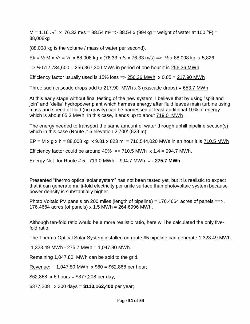
Page 34 of 54
M = 1.16 x 76.33 m/s = 88.54 m³ => 88.54 x (994kg = weight of water at 100 ⁰F) =
88,008kg
(88,008 kg is the volume / mass of water per second).
Ek = ½ M x V² = ½ x 88,008 kg x (76.33 m/s x 76.33 m/s) => ½ x 88,008 kg x 5,826
=> ½ 512,734,600 = 256,367,300 MWs in period of one hour it is 256.36 MWh
Efficiency factor usually used is 15% loss => 256.36 MWh x 0.85 = 217.90 MWh
Three such cascade drops add to 217.90 MWh x 3 (cascade drops) = 653.7 MWh
At this early stage without final testing of the new system, I believe that by using “split and join” and “delta” hydropower plant which harness energy after fluid leaves main turbine using mass and speed of fluid (no gravity) can be harnessed at least additional 10% of energy which is about 65.3 MWh. In this case, it ends up to about 719.0 MWh .
The energy needed to transport the same amount of water through uphill pipeline section(s) which in this case (Route # 5 elevation 2,700‘ (823 m):
EP = M x g x h = 88,008 kg x 9.81 x 823 m = 710,544,020 MWs in an hour it is 710.5 MWh
Efficiency factor could be around 40% => 710.5 MWh x 1.4 = 994.7 MWh.
Energy Net for Route # 5: 719.0 MWh – 994.7 MWh = - 275.7 MWh
Presented “thermo optical solar system” has not been tested yet, but it is realistic to expect that it can generate multi-fold electricity per unite surface than photovoltaic system because power density is substantially higher.
Photo Voltaic PV panels on 200 miles (length of pipeline) = 176.4664 acres of panels ==>. 176.4664 acres (of panels) x 1.5 MWh = 264.6996 MWh.
Although ten-fold ratio would be a more realistic ratio, here will be calculated the only five-fold ratio.
The Thermo Optical Solar System installed on route #5 pipeline can generate 1,323.49 MWh.
1,323.49 MWh - 275.7 MWh = 1,047.80 MWh.
Remaining 1,047.80 MWh can be sold to the grid.
Revenue: 1,047.80 MWh x $60 = $62,868 per hour;
$62,868 x 6 hours = $377,208 per day;
$377,208 x 300 days = $113,162,400 per year;

Page 35 of 54
Preliminary Pipeline Cost Estimate
Preliminary cost estimate for Pipeline Route # 1:
The range of cost today of installed pressure pipe of 48-inch diameter in various terrains is about $600 – $1,000 per linear foot. Here is used most conservative option $1,000 per linear foot.
The Route # 1 has a distance of about 150 miles with preferred topography which has an advantage in pipeline cost. Let’s assume $600 per linear foot.
One mile 5,280 ‘ x $600 = $3,168,000.
$3,168,000 x 450 miles relatively flat terrain (50 miles x 5 pipelines + 50 miles x 3 pipelines 50 miles 1 pipeline) = $1,425,600,000
Because of a new product development + several pumping stations which will work temporally + final “delta” power plant on the final route + adding several freeway underpasses, right-of-way permits - the final cost might increase 20% to about $1.7 billion.
If the option - to pump out high salinity water from bottom of the lake into vast Ocean - is accepted through negotiation with Mexico authorities then the same presented pumping system for importing seawater can be used for exporting high salinity water (concentrated salty water at the bottom of the lake) from the Salton Sea into the Ocean by switching direction of rotation of the In-Line-Pump/Generator 572 and 573. Reverse flow can be activated periodically for example: two weeks per year twice a year.
Preliminary cost estimate for Pipeline Route # 2:
The range of cost today of installed pressure pipe of 48-inch diameter in various terrains is about $600 – $1,000 per linear foot. Here is used most conservative option $1,000 per linear foot. A mile = 5,280’ x $1,000 = $5,280,000;
The Route # 2 has distance of about 150 miles.
$5,280,000 x 375 miles (75 miles uphill x 5 pipelines) = $1,980,000,000.
$5,280,000 x 75 miles (75 miles downhill x 1 pipeline) = $396,000,000.
$2,376,000,000
Connecting the Salton Sea with Pacific Ocean (San Diego area) distance about 150 miles - 75 miles uphill (5 pipelines) + 75 miles downhill (1 pipeline ) it ends up to about $2.376 billion.
Because of mountain terrain + development of a new product + several pumping stations + several tanks on uphill route + several “split and join” power plants + final “delta” power plant on the final route + adding several freeway underpasses, right-of-way permits - the final cost might increase 40% to about $3.32 billion.
Page 36 of 54
If the option - to pump out high salinity water from bottom of the lake into vast Ocean - is accepted through regulatory agencies and authorities then the same presented pumping system for importing seawater can be used for exporting high salinity water (concentrated salty water at the bottom of the lake) from the Salton Sea into the Ocean by switching direction of rotation of the In-Line-Pump/Generator 572 and 573. Reverse flow can be activated periodically for example: two weeks per year twice a year.
Preliminary cost estimate for Pipeline Route # 3:
The Route # 3 has distance of about 160 miles.
$5,280,000 x 400 miles (80 miles uphill x 5 pipelines) = $2,112,000,000.
$5,280,000 x 80 miles (80 miles downhill x 1 pipeline) = $422,400,000.
Connecting the Salton Sea with the Pacific Ocean (San Diego area) distance about 160 miles - 80 miles uphill (5 pipelines) + 80 miles downhill (1 pipeline ) it ends up to about $2,534,400,000.
Because of mountain terrain + development of a new product + several pumping stations + several tanks on uphill route + several “split and join” power plants + final “delta” power plant on the final route + adding several freeway underpasses, right-of-way permits - the cost might increase 40% to about $3.5 billion
If the option - to pump out high salinity water from bottom of the lake into vast Ocean - is accepted through regulatory agencies and authorities then the same presented pumping system for importing seawater can be used for exporting high salinity water (concentrated salty water at the bottom of the lake) from the Salton Sea into the Ocean by switching direction of rotation of the In-Line-Pump/Generator 572 and 573. Reverse flow can be activated periodically for example: two weeks per year twice a year.
Preliminary cost estimate for Pipeline Route # 4:
The Route # 4 has distance of about 100 miles which has an advantage in pipeline cost
$5,280,000 x 250 miles (50 miles uphill x 5 pipelines) = $1,320,000,000.
$5,280,000 x 50 miles (50 miles downhill x 1 pipeline) = $264,400,000.
Connecting the Salton Sea with the Pacific Ocean (San Diego area) distance about 100 miles - 50 miles uphill (5 pipelines) + 50 miles downhill (1 pipeline ) it ends up to about $1.584 billion.
Because of mountain terrain + development of a new product + several pumping stations + several tanks on uphill route + several “split and join” power plants + final “delta” power plant If the option - to pump out high salinity water from bottom of the lake into vast Ocean - is

Page 37 of 54
accepted through regulatory agencies and authorities then the same presented pumping system for importing seawater can be used for exporting high salinity water (concentrated salty water at the bottom of the lake) from the Salton Sea into the Ocean by switching direction of rotation of the In-Line-Pump/Generator 572 and 573. Reverse flow can be activated periodically for example: two weeks per year twice a year.
Preliminary cost estimate for Pipeline Route # 3:
The Route # 3 has distance of about 160 miles.
$5,280,000 x 400 miles (80 miles uphill x 5 pipelines) = $2,112,000,000.
$5,280,000 x 80 miles (80 miles downhill x 1 pipeline) = $422,400,000.
Connecting the Salton Sea with the Pacific Ocean (San Diego area) distance about 160 miles - 80 miles uphill (5 pipelines) + 80 miles downhill (1 pipeline ) it ends up to about $2,534,400,000.
Because of mountain terrain + development of a new product + several pumping stations + several tanks on uphill route + several “split and join” power plants + final “delta” power plant on the final route + adding several freeway underpasses, right-of-way permits - the cost might increase 40% to about $3.5 billion
If the option - to pump out high salinity water from bottom of the lake into vast Ocean - is accepted through regulatory agencies and authorities then the same presented pumping system for importing seawater can be used for exporting high salinity water (concentrated salty water at the bottom of the lake) from the Salton Sea into the Ocean by switching direction of rotation of the In-Line-Pump/Generator 572 and 573. Reverse flow can be activated periodically for example: two weeks per year twice a year.
High salinity water (brine) has higher density and has a tendency to accumulate at the lowest point(s) at the bottom of the lake where can be accessed, pump it up and used in a new design of geothermal power plants for generation of electricity, and as byproducts produce potable water and lithium.
As an option - we could pump out high salinity water from bottom of the lake with a single pipeline 24” diameter and disperse it into Ocean: A few miles offshore near Carlsbad there is a trench called “Carlsbad Canyon” through which high salinity water would slide slowly into depth of the Ocean and find its way to join existing currents in the vast ocean without negative effect on marine life. Such option might add about 30% to the cost of each route.
Hypersaline water – brine - is in sync with natural occurrence in oceans and together with temperature difference the main engine in currents circulation in Oceans - called “deep ocean currents” or thermohaline circulation.
Preliminary estimate for energy needed to pump out and transport high salinity water from bottom of the lake and transport it into the Ocean - Route # 1:
Page 38 of 54
Diameter of pipe is 24” = 2’
= 3.14 x 1² = 3.14 f² 3.14 f² / 9 = 0.348 y² = 0.2916 m²
Mass = 0.2916 m² x 10 meter per second (estimated reasonable speed) = 2.9 m³ =>
2.9 m³ x (994 kg = weight of water at 100 ⁰F) = 2,882.6 kg
(2,882 kg is the volume / mass of water per second).
The energy needed to transport the same amount of water through uphill pipeline section(s) which in this case (Route # 1) is 262‘ (80 m):
EP = M x g x h = 2,882 kg x 9.81 x 80 m = 2,261,793.6 MWs in an hour it is 2.3 MWh
Efficiency factor could be around 40% => 2.3 MWh x 1.4 = 3.22 MWh.
Energy Net for Route # 1: 27.3 MWh – 3.2 MWh = 24 MWh
The volume of outflow water is:
0.348 y² x 10 meter per second = 3.48 y³ x (31,536,000 seconds in a year) = 109,745,280 y³ ==> 68,023.93 acre-foot.
Preliminary estimate for energy needed to pump out and transport high salinity water from bottom of the lake and transport it into the Ocean - Route # 2:
Diameter of pipe is 24” = 2’
= 3.14 x 1² = 3.14 f² 3.14 f² / 9 = 0.348 y² = 0.2916 m²
Mass = 0.2916 m² x 10 meter per second (estimated reasonable speed) = 2.9 m³ =>
2.9 m³ x (994 kg = weight of water at 100 ⁰F) = 2,882.6 kg
(2,882 kg is the volume / mass of water per second).
The energy needed to transport the same amount of water through uphill pipeline section(s) which in this case (Route # 2) is 1,600‘ (488 m):
488 meters + (70 meters Ocean to Lake difference) = 558 meters
On this route can be used 6 uphill pumping stations about 100 meters each.
EP = M x g x h = 2,882 kg x 9.81 x 100 m = 2,827,242 MWs in an hour it is 2.83 MWh
Efficiency factor could be around 40% => 2.83 MWh x 1.4 = 3.96 MWh.
3.96 MWh x 6 pumping stations = 23.76 MWh.

Page 39 of 54
It is realistic to expect that outflow in downhill routes can generate 10% of energy used for uphill route which is 2.4 MWh.
Energy Net for outflow for Route # 2: 23.76 MWh – 2.4 MWh = 21.36 MWh
Preliminary estimate for energy needed to pump out and transport high salinity water from bottom of the lake and transport it into the Ocean - Route # 3:
Diameter of pipe is 24” = 2’
= 3.14 x 1² = 3.14 f² 3.14 f² / 9 = 0.348 y² = 0.2916 m²
Mass = 0.2916 m² x 10 meter per second (estimated reasonable speed) = 2.9 m³ =>
2.9 m³ x (994 kg = weight of water at 100 ⁰F) = 2,882.6 kg
(2,882 kg is the volume / mass of water per second).
The energy needed to transport the same amount of water through uphill pipeline section(s) which in this case (Route # 3) is 2,700‘ (823 m):
823 m + (70 meters Ocean to Lake difference) = 893 meters
On this route can be used 9 uphill pumping stations about 100 meters each
EP = M x g x h = 2,882 kg x 9.81 x 100 m = 2,827,242 MWs in an hour it is 2.83 MWh
Efficiency factor could be around 40% => 2.83 MWh x 1.4 = 3.96 MWh.
3.96 MWh x 9 pumping stations = 35.64 MWh.
It is realistic to expect that outflow in downhill routes can generate 10% of the energy used for the uphill route which is 3.5 MWh.
Energy Net for outflow for Route # 3: 35.64 MWh – 3.5 MWh = 32.14 MWh
[0165] Preliminary calculation for the cost of two solar system used in this proposal:
Although the length of most of the proposed pipeline routes is about 160 miles here for easier
calculation will be calculated the length of pipeline to be 1 miles. For any particular distance,
final results can be easily calculated.
I) Solar PV panels: There are two solar panels assembly 610 on each segment of the
pipeline (see slide 70 / FIG. 106). One solar assembly 610 has two sets of three panels of
dimensions about 3.5’ x 5.2’. Length of on segment of the pipeline is about 30 ‘.

Page 40 of 54
1 mille : 30’ = 5,280 feet : 30’ (segment) = 176 pipeline segments.
One set of panels
5.2’ x 3.5’ = 18.2 square feet; => 18.2 square feet x 6 panels = 109.2 square feet.
109.2 square feet x 2 assembly = 218.4 square feet.
218.4 square feet (two assembly) x 176 (segments) = 38,438.4 square feet.
38,438.4 square feet = 0.882332 acres.
One mile of pipeline can have 0.882332 acres of panels.
0.882332 acres (of panels) x 100 miles (length of pipeline) = 88.2 acres of panels.
(1 acre of solar panels produces 1.5 MWh – 1.68 MWh).
88.2 acres (of panels) x 1.5 MWh = 132.34 MWh
0.882332 acres (of panels) x 160 miles (length of pipeline) = 141.137 acres of panels.
141.137 acres (of panels) x 1.5 MWh = 211.75968 MWh.
Presented “thermo optical solar system” has not been tested yet, but it is realistic to expect that it can generate multi-fold electricity per unite surface than photovoltaic system because power density is substantially higher.
Although ten-fold ratio would be more realistic ratio, here will be calculation only five-fold ratio.
[0166] Preliminary cost estimate of solar panel assembly:
Preliminary cost estimate of one set of the “Thermo Optical Solar (TOS) panel assembly
(610) cost about $ 2,000. Preliminary estimate is that two sets of the “Thermo Optical Solar
(TOS) panel assembly (610) assembled on one pipeline segment 30 feet long cost about
$4,000 (See slide 70 / FIG. 106).
[0167] 176 (pipeline segment per mile) x $4,000 = $704,000; Assuming that every two
pipeline segments there is a power unit and a battery.
[0168] Preliminary cost estimate of one power unit is $3,000; Preliminary cost estimate of
one battery unit is $3,000; Let’s call it power pack $6,000.
176 segments : 2 = 88 power pack; 88 power pack x $6,000 = $528000;

Page 41 of 54
For one mile the cost of (88 power pack = $528,000) + (352 Thermo Optical Solar (TOS)
panel assembly = $704,000) = $1,232,000;
For 160 miles the cost is $197,120,000 ~ $200,000,000;
Summary of the Preliminary Analyzes of several Route options:
Route # 1 - Importing seawater from the Gulf of California – corridor: San Felipe - Mexicali, Mexico, - Salton Sea.
Elevation to overcome is 35 ‘ (10 m); Pipeline distance is about 150 miles; Cost estimate for pipeline: $1.7 billion; Cost estimate for TOS: $184.8 million; Route #1 would generate hydropower: 27.3 MWh; The Thermo Optical Solar System installed on pipeline would generate 1,058.79 MWh; Revenue generated from the Thermo Optical Solar (TOS) System installed on pipeline Route #1 would be at least $114,349,320 per year; Revenue generated from the “Delta” hydro power plant would be $13,759,200 per year; Revenue total: $128,108,520 per year;
Route # 2 - Importing seawater from the Ocean – corridor: Oceanside - Temecula - San Jacinto - (existing tunnel) - Cabazon - Salton Sea.
Elevation to overcome is 1,600‘ (488 m); 2 cascades each with 279 m drop and 6 uphill pumping stations; Pipeline distance is about 160 miles; Cost estimate for pipeline: $3.32 billion; Cost estimate for TOS: $200 million Energy needed for operation of the pipeline: 134.5 MWh; The Thermo Optical Solar System installed on route #2 pipeline can generate 1,058.79 MWh; Remaining 924.30 MWh can be sold to the grid;
Revenue generated from the Thermo Optical Solar (TOS) System installed on pipeline Route #2 would be at least $99,824,400 per year;
Route # 3 - Importing seawater from the Ocean – corridor: Oceanside - Temecula - San Jacinto - Beaumont – Salton Sea.
Elevation to overcome: 2,700‘ (823 m). 3 cascades each with 297 m drop and 9 uphill pumping stations. Pipeline distance: about 170 miles. Cost estimate for pipeline: $3.5 billion. Cost estimate for TOS: $209.44 million Energy needed for operation of the pipeline: 275.7 MWh;

Page 42 of 54
The Thermo Optical Solar System installed on the Route #3 pipeline can generate 1,124.97 MWh; Remaining 849.27 MWh can be sold to the grid; Revenue generated from the Thermo Optical Solar (TOS) System installed on pipeline Route #3 would be at least $91,721,160 per year;
Route # 4 - Importing seawater from the Ocean – corridor: Oceanside - Temecula - Borrego - Springs –.Salton Sea.
Elevation to overcome is 3,600‘ (1,097 m); 4 cascades each with 292 m drop and 11 uphill pumping stations; Pipeline distance: about 100 miles; Cost estimate for pipeline: $2.22 billion; Cost estimate for TOS: $123,200,000 million; Energy needed for operation of the pipeline: 380 MWh; The Thermo Optical Solar System installed on route #4 pipeline can generate 661,7 MWh; Remaining 281.7 MWh can be sold to the grid; Revenue generated from the Thermo Optical Solar (TOS) System installed on pipeline Route #4 would be at least $30,423,600 per year.
Route # 5 - Importing seawater from the Ocean – corridor: Long Beach - Whitewater – Salton Sea.
Elevation to overcome: 2,700‘ (823 m); 3 cascades each with 297 m drop and 9 uphill pumping stations; Pipeline distance: about 200 miles; Cost estimate for pipeline: $4.118 billion; Cost estimate for TOS: $246,400,000 million; Energy needed for operation of the pipeline: 275.7 MWh; The Thermo Optical Solar System installed on route #5 pipeline can generate1,323.49 MWh; Remaining 1,047.80 MWh can be sold to the grid; Revenue generated from the Thermo Optical Solar (TOS) System installed on pipeline Route #5 would be at least $113,162,400 per year.
NOTE: This proposal is a preliminary design explaining the feasibility of the concept. The second stage would require collaboration with potential contractors and would contain more details, including more detailed cost estimate, which would follow with the final production design.
Benefits of the presented proposal for the restoration of the Salton Sea:
In Summary – Presented proposal for the restoration of the Salton Sea includes an architectural element which harmoniously incorporates several patented technologies into a self-sustaining organism.
Page 43 of 54
The proposal has the following benefits:
a) It is a long-term solution for the restoration of the Salton Sea and our community and it can be considered as a “Project of the Century”;
b) By dividing the lake into three sections with two main dikes (two lane roads) it would prevent further pollution of the central part of the lake with runoff waters from nearby farms which contain fertilizers, pesticides, and sewer from Mexicali, Mexico.
c) Optionally, if we, the USA, are successful in negotiation with Mexico’s officials, at least for redirecting flow of the New River and Alamo River back in Mexico, and by implementing pipeline with sprinkler system for farmland, then we will not have to deal with runoff water from farmland entering the Lake.
d) Treating runoff water (all current inflow) in the northern and southern section of the lake naturally with gravity, mangrove trees and, if needed, other appropriate treatments, and then reusing treated water for farmland. It would provide a substantial amount of water for farmland even after the enforcement of the QSA. In fact, presented proposal is in harmony with reduction of inflow from canal after the enforcement of the QSA. NOTE: At the present time purpose for farmland’s runoff water is to compensate for evaporation of the lake and cannot be used for farmland as it merges with the salty water of the lake.
e) Dividing the lake into three sections would provide vast wildlife sanctuary and visitor attraction. Birds can choose which section to inhabit.
f) Importing water from the Pacific Ocean in the central section of the lake with a pipeline system (Illustrated in the Power Point slides 27) and maintaining the water level of the lake as it was in the 1950s and 60s would provide condition for tourism. It would also eliminate the needs for expensive the “Salton Sea Management Program“, whose purpose is to constantly mediate toxic dust storms induced by soon exposed 100s square miles of lakebed of the depleting Lake.
g) Importing water from the Pacific Ocean in the central section of the lake and extracting concentrated salty water from the bottom of the lake would desalinate the lake almost to the level of the seawater in a few years and would provide a condition for tourism (hotels, motels, resorts, beaches, waterfront properties, etc.).
h) Presented system for harnessing geothermal energy the “Scientific Geothermal Technology” which uses breakthrough technology - completely closed loop system can generate much more electricity than conventional geothermal power plants because it is not limited to the existing geothermal reservoirs and can be built nearby the Lake without damaging Lake’s original coastline and condition for tourism.
i) It would generate a substantial amount of potable water from seawater as a byproduct with no additional expenses for it and the lake could serve in the future as a hub station for the production and distribution of new produced potable water throughout other areas of the desert.

Page 44 of 54
j) It would provide an inexpensive super saturated brine as byproduct - a source for extraction of lithium.
k) It would generate $100s billion in revenue (electricity, tourism, lithium) in a few decades for our communities and would continue so in the future.
l) It would provide a clean environment by maintaining water level of the lake of the 1950s and 60s and subsequently preventing depletion of the lake and formation of toxic dust storms.
m) It would employ many people during construction and after construction of the project.
n) It would cost about $10 billion, with the final result of “really” saving the Salton Sea. (About 3.5 billion dollars for the pipelines; about $2 billion for solar system associated with pipeline; about $3 billion for dikes and wetlands – wildlife sanctuary; and about $1 billion for three Power Plants – one for each sector). Phase V will be continuation of building hundreds of Power Plants – private sector to get involved and future generation to continue where our generation started.
o) Even if the cost of the project is $20 billion - it is imperative that we do it. Because it would not just eliminate incoming environmental disaster which would cost, according to the Pacific Institute, over $70 billion in health issues of the population (asthma, cancer, etc.), drop of property value, and losing businesses - but it would provide condition for tourism, exclusive real estate, generation of electricity, generation of potable water and clean environment.
p) The main value of my proposal and methodology is the simplicity of it and the necessity for it. An average high school student can understand it in a relatively short period of time.
q) Presented proposal transforms a situation of an incoming environmental disaster (liability) into the situation of a clean environment and prosperity (assets).

Page 45 of 54
Date: 12/8/17 To: All interested Parties Re: Request for Information for Salton Sea Water Importation Projects Under the leadership of Governor Edmund G Brown Jr., the 2014 California Water Action Plan set forth a vision for California water management that balances statewide water supply security with the protection of public, economic and ecological health. The California’s Salton Sea Management Program (SSMP), led by the California Natural Resources Agency (CNRA) is designed to address public and ecological health issues at the Salton Sea while securing Colorado River water supplies for the state. The SSMP is a long-range program that concentrates on the immediate need for habitat and air quality protections and includes the development of a long-range plan as part of the first Phase I Ten Year Plan. The SSMP takes a phased, incremental approach of habitat and other dust suppression projects to protect air quality and ecosystem values at a smaller and sustainable Salton Sea. The Phase I Ten-Year Plan concentrates on the development of constructed projects at the north and south end of the lake where the playa exposure is the greatest and water inflows are most available. This Request for information (RFI) outlines the information requested by CNRA to evaluate proposals for a water import project to meet long-range goals of the SSMP. The intent of the RFI process is to gather information on the proposed water import projects. The information received will be reviewed and may be included in the long-range plan for the Salton Sea. Submission Requirements Submission Deadline: Responses to this RFI should be sent to Bruce Wilcox at [email protected] by March 9, 2018. Questions: Questions or requests for clarification on the content of the RFI should be directed to Bruce Wilcox at [email protected]. The question period closes on January 31st; questions received will be answered and posted on the CNRA web page after that date. All questions will be answered through the process noted above, no answers will be provided to individual emails. Required Information: The following information is required as part of the submittal. The information should be presented in the format noted (i.e. Section 1 Project Team, Section 2 Narrative Description…). If requested information is not available, the proposal should include

Page 46 of 54
as much detail as available and steps needed to gather the required information. The respondent should note if any portion of their response should be considered proprietary and not be shared publicly. 1. Identification of Project Team Members of the project team, and their roles on the project should be identified. 2. Narrative description of project concept and how/when it will benefit the lake. A brief description of the proposed project is required that includes a general discussion of the project concept, the business plan and the implementation of the project. The project concept discussion should include a description of the project and how it will improve conditions at the lake. The business plan should include a discussion of the ownership of the proposed project and the plan for generating revenue from the project. 3. Planning and design process of project
Describe the planning process completed to date and detail how the planning process will be completed. The description should include the following:
• Project Feasibility -- Documentation of the engineering feasibility of the project.
Documentation should include at a minimum: system capacity; pumping requirements; channel and pipe size; water quality; other associated infrastructure such as desalinization, fish or trash screens, etc.; and expected energy use.
• Water Source Identification – Either provide documentation from the water rights holder that establish the willingness of the water rights holder to allow use of their water right or provide detailed description of process to establish those rights.
• Land Use – provide project route alignment and status of land use permission for the conveyance route both in the United States and in Mexico.
• Environmental Impact – provide information on any anticipated environmental impacts from the project in both Mexico and the US and how those will be generally mitigated. This should include a discussion of any anticipated impacts to existing surface water use, groundwater basins, and wildlife resulting from the introduction of ocean water to existing, or new, river channels or canals. If the project is proposed within the Alto Golfo de California Biosphere Reserve, please identify any anticipated impacts to that area and expected mitigation measures.
• Salton Sea Salinity – how does the project plan to deal with increased salinity at the Salton Sea from the imported ocean water? If the proposed project includes a desalinization system where will the resulting brine be deposited?
• Water Use – Describe the projected water balance including consumptive use, system loss, evaporation etc. and ability of the proposed project to operate successfully with decreased flows.
• Cross Border Governmental Coordination and Permitting -- provide details of conducted or needed coordination and permitting from governmental agencies from both Mexico and the United States that deal specifically with cross border

Page 47 of 54
project development. Agencies include but are not limited to the International Boundary Water, Commission, Mexico federal agencies, tribal governments, and necessary United States agencies.
• Project Development Schedule -- Schedule for project development from current stages through implementation.
• Operation Schedule -- Provide an estimate of the length of time necessary for the proposed project to raise the water levels at the lake to recover potentially emissive playa.
4. Cost projection • Provide a cost projection for the proposed project. The projection should be
documented to the extent that the reviewers can review the cost projection process and determine the validity of the projections
5. Plan for funding of proposed project • Describe how the planning, design and construction implementation of the
project will be funded.
• Identify the responsible parties for the operation and maintenance for the project and estimate annual cost.
***

Page 48 of 54
1. Identification of Project Team
A. My name is Nikola Lakic. I am an architect and author of the presented concept for the restoration of the Salton Sea. I am the inventor of a new methodology for harnessing geothermal energy and a new solar system which I have modified in presented proposal to incorporate local condition of the Salton Sea area.
Our mission at Geothermal Worldwide, Inc., is to license our IP – and support the integration of its processes worldwide including the Salton Sea project:
"Self Contained In-Ground Geothermal Generator (SCI-GGG);
"Self Contained In-Ground Heat Exchanger" (SCI-GHE);
“In-Line-Pump/Generator”;
“Apparatus for drilling deeper and wider well-bores”;
Thermo Optical Solar (TOS) system; to the interested and capable parties worldwide.
2. Narrative description of project concept and how/when it will benefit the lake.
A. It is a substantial presentation. Please read it all thoroughly. 3. Planning and design process of project.
A. I am not a contractor betting for a specific task. I am providing a preliminary master plan - a feasible solution for the restoration of the Salton Sea. Cooperation with the CNRA and SSA and other relevant agencies is needed. I am respectfully suggesting radical change in current policy regarding future of the Salton Sea. Please refer to the segment below “Additional Information, Observation and Suggestions”.
For time schedule please refer to slide 85 in Power Point Presentation included. Regarding Cross Border Governmental Coordination and Permitting:
The Logan Act (18 U.S.C.A. § 953 [1948]) is a single federal statute making it a crime for a citizen to confer with foreign governments. Specifically, it prohibits citizens from negotiating with other nations on behalf of the United.
Therefore I am suggesting that the CNRA - SSA and the State officials - put some effort in forming a team preferably the same team lead by Mr. Dana Bart Fisher, Jr. Chairman of Colorado River Board of California that have finalized Colorado River deal with Mexico team in August 2017. I am willing to help our team.

Page 49 of 54
We, the USA, could use, as leverage, my technology, for production of potable water for Mexicali which they desperately need (See slides 27 & 77) in return for achieving our goals. Tips for negotiation with Mexico’s team: Our government could negotiate a treaty with Mexico for access to seawater;
Arguments and solution for negotiation with Mexico regarding import of seawater and leverage for negotiation:
Current Situation:
1. We need seawater from Gulf of California.
2. Mexico needs potable water for the Mexicali and surrounding cities.
3. We (USA) are receiving sewer from Mexicali the New River which pollute the Salton Sea. (Gravity doesn’t recognize border).
4. Droughts of 18 years and enforcement of the QSA requires fast action in reduction of use of Colorado River.
Proposal for the negotiation for importing seawater from the Gulf of California: a) Our (US) interest: To import seawater from the Gulf of California and to provide
circulation for the Salton Sea by exporting water from the Salton Sea into Gulf of California. b) To get corridor for pipeline preferably with fence around it for maintenance – 100
years lease or second option 75 years lease with option of instant extension for 25 years or something alike. If needed some area of pipeline route can be underground for roads over pipelines and continuity of their territory.
c) Mexico’s interest: They need potable water for Mexicali and surrounding cities; They need water for farmland. The solution of mutual interest is: Redirecting the Alamo River and New River flow before entering USA and filing with it the Laguna Salada and eventually reestablish route to the Gulf of California - preferably treated before entering the Gulf of California. (see slide 27 in Power Point Presentation).
Such solution would be desirable achievement by Mexico’s officials. They would welcome such proposal. It would be of mutual interest.
To use this proposal (solution) as leverage in obtaining access to exchanging waters without paying for importing seawater.
Page 50 of 54
e) To introduce the Scientific Geothermal Technology to Mexico’s officials to be used in area of Serro Preto to harness geothermal energy and to have byproduct potable water – in return for sharing expenses for the pipeline from the Gulf of Mexico to the border of USA.
The Scientific Geothermal Technology is superior to contemporary geothermal systems, for production of electricity, potable water for Mexicali, which they desperately need, and production of lithium.
4. Cost projection A. It is a substantial presentation. Please read it all. For summary please refer to included slides 80 - 84 in PowerPoint Presentation.
5. Plan for funding of proposed project A. The presented proposal for the restoration of the Salton Sea is a Long-Term solution, which includes an architectural element which harmoniously incorporates several patented technologies in a self-sustaining organism. It includes a new pipeline technology with “In-line-Pumps/Generators which is a more efficient way for transporting water than conventional pipeline system because in downhill routes generate electricity which can be used as a supplement to the energy needed for uphill routes. It includes solar panels installed on top of a pipeline for generation of electricity which can be used for pumping water over mountains (uphill routes). It includes a new thermo-optical solar system which is a practical and efficient system for harnessing solar energy. Some part of electricity generated can be used for the operation of the pipeline and rest can be sold to the grid and used towards repaying the project.
It includes a new methodology for harnessing geothermal energy using completely closed loop system for transferring heat from a source of heat (hot rocks or hot water) to the boilers of the power plants on ground surface where electricity is generated and also potable water as a byproduct. A portion of generating profit can be used towards repaying the project.
It includes a new drilling system for drilling deeper and wider wellbore which is a more efficient way (faster and in long-term cheaper) for drilling wellbores than conventional drilling systems. It includes a new methodology for desalinization of salt water which is a more efficient way of desalinization than a conventional system such as reverse osmoses.
Therefore, it is reasonable to expect that the state and federal governments should and very possibly would provide necessary funding for the implementation of first three phases of the presented proposal for the restoration of the Salton Sea. Funding can be a grant or low-interest long-term loan because this project will generate hundred billion dollars in revenue in several decades and will provide a clean environment and would divert incoming eco-disaster with liabilities over 70 billion dollars. The first three phases: first phase – building

Page 51 of 54
pipeline for importing seawater; and second phase – dividing lake in three sections with two main dikes; and third phase – building at least one power plant on each sector – are necessary foundations for development of additional phases which includes hundreds power plants and condition for tourism where private sector will have a chance to get involved.
Another reason for the state and federal government to get involved is that the state and federal government pay a substantial amount of money for many programs in order to find a solution for transfer from pollutants such as coal, oil, nuclear energy to clean energy, energy efficiency and sustainability. The presented proposal provides the solution for those problems.
Since pipeline will be passing through different counties and different land ownership, the ownership and maintenance need to be done on state and federal level in combination with municipally and the private sector. Involvement of the California Natural Resources Agency (CNRA) and Salton Sea Authority (SSA) is needed in coordinating the projects.
The revenue that presented project will generate will be shared by participants according to their involvement. I, as the CEO of the Geothermal Worldwide Inc., and as the author of the proposal and author of new breakthrough technologies involved in this project will be selling licenses to capable companies for technology used and that way generates income as is standard practice in the industry in similar situations.
Additional Information Observation and Suggestions.
~ The virtue of the late Steve Jobs, the CEO of the Apple, was the ability to make so-called a “turn on a dime” when he saw a better solution despite previous investments. That is
characteristic of the intelligent person - which is quite different from those who continue with projects doomed to fail just because they have already committed to something or have
invested in something - quite often taxpayers’ money. ~
A few words about the Salton Sea Management Program (SSMP) and its contradictions: I am reluctant to criticize someone else design but since we are in an emergency situation – environmental disaster is approaching and health of public is in question – and we are 15 years late in finding a long-term solution for the restoration of the Salton Sea, – I am taking liberty to point out on falseness and contradictions in current policy already in motion a “Smaller and Sustainable Lake” led by California Natural Resources Agency (CNRA), which is not in the best interest to the Salton Sea, environment and health of the public. My criticism is in a good fate and I am hoping that the CNRA will take my observation objectively without prejudice. My observations of the falseness of the Salton Sea Management Program (SSMP) are following:

Page 52 of 54
1. The “Smaller, Sustainable Lake” option which is the essence of the existence of the Salton Sea Management Program (SSMP) was initiated and accepted on a false assumption that the “Smaller Lake” option is the only feasible solution. 2. Very possible the initiation and approval of the SSMP by Governor Brown in May 2015, was done without Governor Brown being informed of the existence of the long-term solution for the restoration of the Salton Sea. 3. The “Smaller, Sustainable Lake” option requires constant support and the existence of the SSMP, which is a costly task without saving the lake – in fact at the end losing the lake. 4. It is well known that the main purpose of the Salton Sea Management Program (SSMP), led by California Natural Resources Agency (CNRA) is to implement dust suppression projects to protect air quality and ecosystem from formation of toxic dust storms on exposed lakebed (playa) which will increase as the lake continue to recede because of insufficient inflow of water, especially after enforcement of the Quantification Settlement Agreement (QSA). 5. The concept of importing seawater and the Salton Sea Management Program (SSMP), as is, cannot logically coexist. If seawater is imported, which is a good idea, then, there is no need for the existence of the “SSMP” and “Ten Year Plan”. 5. If seawater is imported, which is a good idea, then, there is no logic in spending tax-payers money on managing exposed playa and keeping a “Smaller, Sustainable Lake”. 6. If seawater is imported, which is a good idea, then, there is no logic in spending tax-payers money on development and construction of the projects on exposed lakebed (playa) at the northern and southern part of the lake. 7. It is well known that there is a geothermal reservoir at the southern part of the lake and that some people are hoping for realization of the “Smaller Lake” option so that they can profit by harnessing geothermal energy from that geothermal reservoir, but they are missing a bigger opportunity. In my presented proposal I have a solution for that. 8. As someone who is familiar with the situation of the Salton Sea and someone who has experience in solving difficult problems, it is my moral obligation to respectfully inform the CNRA about the falseness of the current motion. The current proposal already in motion a “Smaller, Sustainable Lake” option, will require constant infusion of funding from state and federal governments for projects intended to suppress formation of toxic dust storm - the projects which are doomed to fail because of lack of inflow water which will gradually decrease and consequently gradually increase exposed lakebed – and finally replace the current lake with a “sustainable cesspool” with liability exceeding $70 billion;

Page 53 of 54
9. One doesn’t need to be a math expert to realize that the Salton Sea - not having outflow and losing by evaporation about 6-8 vertical feet per year and having inflow mostly farmland’s runoff water which contains fertilizers and pesticides and sewer from Mexicali that the lake will be smaller, saltier, smellier, more polluted and the situation will only worsen and the lake - will sooner or later end up as “sustainable cesspool”.
10. Base on well-documented statement and actions, it is obvious that the State – the California Natural Resources Agency (CNRA) - has no feasible plan for a long-term solution for the restoration of the Salton Sea. It is obvious that implementation of the SSMP is not in the best interest of the Salton Sea, environment and health of the public. 11. As for any project, especially if it is of great importance and value for the State and communities, it is imperative to have, first, a feasible plan (blueprint) then to follow the plan accordingly. It is not a good idea to start building anything without a plan and then hope that some miracle might happen later.
I am hoping that the California Natural Resources Agency (CNRA) and reviewers will take my remarks above as objective observation with good intentions. I respectfully urge the California Natural Resources Agency (CNRA) and reviewers to be objective in evaluating of the whole situation; to study thoroughly all elements of the proposal and to focus on saving the Salton Sea, environment, public health, ecosystem, and economy. I respectfully urge the California Natural Resources Agency (CNRA) and reviewers to inform Governor Brown and other state agencies about the existence of the long-term proposal as I did urge the Salton Sea Long-Range Plan Committee during my presentation on February 25, 2016. I am hoping that wisdom and a common sense will prevail and that the SSMP will put effort in redirecting allocated money for the restoration of the Salton Sea towards work on the “long-term” solution for the restoration of the Salton Sea and to achieve functional lake in 3-4 years, and not to lose ten years of precious time and substantial amount of money on projects that will not contribute to the real restoration of the Salton Sea. I respectfully urge reviewers not to do “cherry picking” or dissect my proposal and try to combine some elements with someone else’s design because it would diminish its function and purpose. If minor adjustment is needed, I would be glad to help and hopefully sustain the original art. It is an imperative that the ego, prestige, personal interest, and special interest is taken out of the equation, especially when dealing with so sensitive issues such as the fate of the Salton Sea, environment, and health of the public.

Page 54 of 54
Regarding the next step: Now that we have a feasible plan for the long-term solution for the restoration of the Salton Sea, I respectfully urge the CNR A and the SSA to inform the local officials including Assemblyman Eduardo Garcia and Senator Hueso and Senator Jeff Stone about the existence of the presented long-term solution for the restoration of the Salton Sea and to respectfully urge them to prepare an amendment to their bill (SB5 – prop 68) to redirect already allocated money for the Salton Sea management programs and to ask for $10 billion.
It is realistic to expect that the State and Federal government will be forthcoming in providing necessary funding because now we have a solution that will generate revenue in hundred billion dollars in several decades and provide clean environment with clean technology - instead just asking for substantial funding for projects that cannot generate revenue and eventually would be doomed to fail with liabilities that would exceed $70 billion.
I am confident that now that we have a feasible plan for the long-term solution for the restoration of the Salton Sea - that will generate substantial revenue and would open a door for private investors to get involved - that the State and Federal governments will be forthcoming in providing the necessary funding.
In closing:
There are two options for decision-makers to choose the fate of the Salton Sea:
Option I) To proceed with the current project already in motion a “Smaller, Sustainable? Lake” – “10 year plan” – “Perimeter Lake” - The projects that will be constantly asking the State and Federal Governments for help (for more money) for fixing never-ending problems - and at the end losing the Lake with liabilities exceeding $70 billion (environmental disaster – toxic dust storms, health issues and economic fold) – and in process benefiting a few companies on expenses of environment and communities;
And
Option II) After reviewing and understanding proposal, preferably to accept it, redirect allocated money and efforts toward its implementation which would restore the Salton Sea to the water level of 1950s and 60s; provide condition for tourism, wildlife sanctuary, clean environment, and generate revenue in 100s Billion Dollars in several decades and would continue so in future. (A few companies that would benefit with the (Option I) would benefit even more with the (Option II).
I respectfully urge the decision makers on the issue of the fate of the Salton Sea to consider all option thoroughly, to consult with experts if needed, and to use common sense.
Geothermal Worldwide, Inc., Actively and Aggressively Enforces its Intellectual Property Rights to the Fullest Extent of the Law.


