Title: G-SERIES ACTUATOR LIFTING AND SUPPORT … · lifting lugs on the drive module. Be sure to...
13
ES 57 ENGINEERING SPECIFICATION Title: G-SERIES ACTUATOR LIFTING AND SUPPORT BRACING Number: ES-57 Revision: F DOCUMENT UNCONTROLLED WHEN PRINTED Page 1 of 13 REVISIONS and APPROVALS Revised to D by: Priyank Agrekar July 29, 2015 Checked by: Dhananjay Gole Release Approved by Girish Dalbhanjan ECO #: VACCO4347 Reason: Revised to E by: Joseph Sun November 4, 2016 Checked by: Matt Christopherson Release Approved by Oscar Jimenez ECO #: VACO127/ VAWCO2984 Revised to E by: Wu Tong April 5, 2017 Checked by: Li Ta Release Approved by Matt Christopherson ECO #: VACO202/VAZCO466/VAMCO8176/VAWCO3040 Reason: 1. Correct Figure 4.2a, add one lifting strap on housing flange power side, and add notes for these three straps in the picture. 2. Add alternative to lifting by using lifting hole in Spring Can Outer End Cap and hoist ring. Related contents: Figure 4.3b, Figure 4.4a, Figure 8.0d, and Figure 8.0e USE OF THIS DOCUMENT The master copy of this document resides in electronic format. Printed copies of this document are for convenience only. Verify that the revision of this printed document matches the current revision of the electronic master before use.
Transcript of Title: G-SERIES ACTUATOR LIFTING AND SUPPORT … · lifting lugs on the drive module. Be sure to...
ES 57 ENGINEERING SPECIFICATION
Title: G-SERIES ACTUATOR LIFTING AND SUPPORT BRACING
Number: ES-57 Revision: F
DOCUMENT UNCONTROLLED WHEN PRINTED Page 1 of 13
REVISIONS and APPROVALS
Revised to D by: Priyank Agrekar July 29, 2015 Checked by: Dhananjay Gole Release Approved by Girish Dalbhanjan ECO #: VACCO4347 Reason: Revised to E by: Joseph Sun November 4, 2016 Checked by: Matt Christopherson Release Approved by Oscar Jimenez ECO #: VACO127/ VAWCO2984 Revised to E by: Wu Tong April 5, 2017 Checked by: Li Ta Release Approved by Matt Christopherson ECO #: VACO202/VAZCO466/VAMCO8176/VAWCO3040 Reason: 1. Correct Figure 4.2a, add one lifting strap on housing flange power side, and add notes for these
three straps in the picture. 2. Add alternative to lifting by using lifting hole in Spring Can Outer End Cap and hoist ring.
Related contents: Figure 4.3b, Figure 4.4a, Figure 8.0d, and Figure 8.0e
USE OF THIS DOCUMENT The master copy of this document resides in electronic format. Printed copies of this document are
for convenience only. Verify that the revision of this printed document matches the current revision of the electronic master before use.

ES 57 ENGINEERING SPECIFICATION
Title: G-SERIES ACTUATOR LIFTING AND SUPPORT BRACING
Number: ES-57 Revision: F
DOCUMENT UNCONTROLLED WHEN PRINTED Page 2 of 13
G-SERIES ACTUATOR LIFTING AND SUPPORT BRACING
1.0 SCOPE
1.1 This specification provides information about lifting, mounting and bracing a Bettis brand G-Series commercial actuator and Valve Operating System (VOS) assemblies using a G-Series actuator.
2.0 PURPOSE
2.1 G-Series actuator consists of modules which are attached to either or both sides of the central drive module such as the spring module, pneumatic power module and / or hydraulic power modules. Bettis brand actuators on their own do not require any kind of external stands or supports other than the support provided by the mounting bracket to the valve’s top works in any valve stem orientation. This specification provides the recommended lifting, handling and supporting for G-Series actuators, including VOS.
3.0 SUPPORT DETAILS
3.1 Actuation technologies recommends that the G-Series actuator be supported by the drive module only. The spring module and power modules are held in position and attached to the drive module securely in any position or orientation without additional support. Extra support or bracing is not required and not recommended. Additional support or bracing is strongly discouraged unless approved by Engineering and could affect the warranty of the actuator.
3.2 The drive module of an actuator will be bolt-mounted directly to a bracket or adaptor that
will be bolted securely to the mounting flange top works of the valve. 4.0 LIFTING DETAILS
4.1 All G-Series Considerations
When handling any G-Series actuators, be aware of tubing, accessories (especially the M11 hand pump) and control panels. Straps and chains can become entangled and cause damage to these components. Never use chains on the spring cartridge as it may warp and cause the actuator not to function correctly or may cause personal injury. These methods can also be applied for lifting Dual and Tandem actuators, but may not need additional support for balance since they have a better center of gravity.
WARNING: NEVER USE THE METHODS IN THIS DOCUMENT TO LIFT ACTUATOR + VALVE + PIPE + ETC. ALWAYS ATTACH TO VALVE TO LIFT THE ACTUATOR + VALVE ASSEMBLY

ES 57 ENGINEERING SPECIFICATION
Title: G-SERIES ACTUATOR LIFTING AND SUPPORT BRACING
Number: ES-57 Revision: F
DOCUMENT UNCONTROLLED WHEN PRINTED Page 3 of 13
4.2 G01X – G3X
The small G-Series actuators should be handled for mounting using properly rated lifting straps and chains. The straps should be around the drive module end flanges. Do not attach any lifting apparatus to the power module nor to the spring return module. Be sure to use an appropriately rated crane / hoist and appropriate straps / chains when raising and lowering the actuator. Never lift the actuator with an attached valve.
Figure 4.2a – Correct Figure 4.2b – Incorrect
ONLY FOR ACTUATOR LIFTING
BALANCE
USE FOR LIFTING ACTUATOR

ES 57 ENGINEERING SPECIFICATION
Title: G-SERIES ACTUATOR LIFTING AND SUPPORT BRACING
Number: ES-57 Revision: F
DOCUMENT UNCONTROLLED WHEN PRINTED Page 4 of 13
4.3 G4X – G7X
The mid-size G-Series actuators should use the lifting lugs/eyes only to handle the actuator. The lifting lugs are rated for the actuator only; not an actuator and connected valve. Always handle actuator / valve assemblies by attaching lifting equipment to the valve only. Be sure to use an appropriately rated crane / hoist and appropriate straps / chains when raising and lowering the actuator.
Figure 4.3a – Only 2 chains are necessary if at opposite corners
Figure 4.3b – Use the lifting hole which on the Outer End Cap
of the Spring module and the hoist ring
ONLY FOR ACTUATOR LIFTING
BALANCE

ES 57 ENGINEERING SPECIFICATION
Title: G-SERIES ACTUATOR LIFTING AND SUPPORT BRACING
Number: ES-57 Revision: F
DOCUMENT UNCONTROLLED WHEN PRINTED Page 5 of 13
4.4 G8X – G13X
The larger actuators can be cumbersome and difficult to move or mount when the side modules are attached. The large spring cartridges are especially difficult and require extra care. Actuation technologies recommends using a head iron or spreader bar and at least two properly rated straps a minimum 3” in width. The straps should be a meter apart to create a basket while the actuator is suspended. This basket should be located between the half way point of the spring cartridge and the first third closest to the drive module as shown below. The majority of the weight will still be handled by use of the lifting lugs on the drive module. Be sure to use an appropriately rated crane / hoist and appropriate straps / chains when raising and lowering the actuator.
Figure 4.4a – Head iron basket + spreader bar + chains
ES 57 ENGINEERING SPECIFICATION
Title: G-SERIES ACTUATOR LIFTING AND SUPPORT BRACING
Number: ES-57 Revision: F
DOCUMENT UNCONTROLLED WHEN PRINTED Page 6 of 13
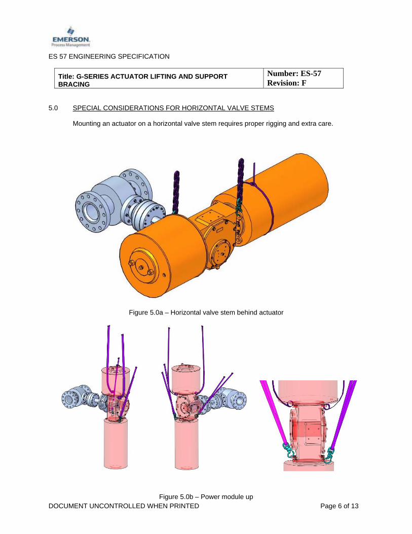
5.0 SPECIAL CONSIDERATIONS FOR HORIZONTAL VALVE STEMS
Mounting an actuator on a horizontal valve stem requires proper rigging and extra care.
Figure 5.0a – Horizontal valve stem behind actuator
Figure 5.0b – Power module up
ES 57 ENGINEERING SPECIFICATION
Title: G-SERIES ACTUATOR LIFTING AND SUPPORT BRACING
Number: ES-57 Revision: F
DOCUMENT UNCONTROLLED WHEN PRINTED Page 7 of 13
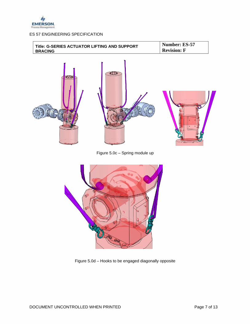
Figure 5.0c – Spring module up
Figure 5.0d – Hooks to be engaged diagonally opposite

ES 57 ENGINEERING SPECIFICATION
Title: G-SERIES ACTUATOR LIFTING AND SUPPORT BRACING
Number: ES-57 Revision: F
DOCUMENT UNCONTROLLED WHEN PRINTED Page 8 of 13
6.0 Lifting of VOS assemblies
The VOS assemblies are more complicated due to the assembled controls, tubing and piping. Extra care should be taken to avoid damage to these components. It is recommended to gradually lift the actuator right till the straps get stretched tight. Final lifting shall be done after making sure that the straps do not touch the controls, tubing or piping of the VOS assembly.
Figure 6.0a – Typical VOS Assembly
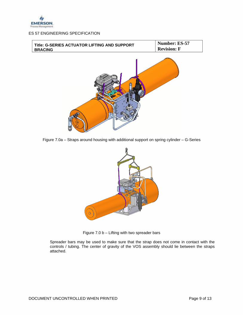
7.0 Actuators without lifting lugs
For actuators without lifting lugs, the VOS assembly may be lifted using straps on both sides of the actuator housing. An additional strap is required to balance the spring cylinder because of its weight and length. Special care should be taken to make sure the straps do not touch or come too close to the assembled controls and tubing / piping.
ES 57 ENGINEERING SPECIFICATION
Title: G-SERIES ACTUATOR LIFTING AND SUPPORT BRACING
Number: ES-57 Revision: F
DOCUMENT UNCONTROLLED WHEN PRINTED Page 9 of 13
Figure 7.0a – Straps around housing with additional support on spring cylinder – G-Series
Figure 7.0 b – Lifting with two spreader bars Spreader bars may be used to make sure that the strap does not come in contact with the controls / tubing. The center of gravity of the VOS assembly should lie between the straps attached.

ES 57 ENGINEERING SPECIFICATION
Title: G-SERIES ACTUATOR LIFTING AND SUPPORT BRACING
Number: ES-57 Revision: F
DOCUMENT UNCONTROLLED WHEN PRINTED Page 10 of 13
8.0 Actuators with lifting lugs:
For actuators with lifting lugs, the VOS assembly should be lifted using straps / chains attached to the lifting lugs using hooks. An additional strap is recommended around the power module in case of double acting actuators and around the spring module in case of spring return actuators for balance only.
Figure 8.0a
Figure 8.0b Figure 8.0c
Strap on the Spring Module for actuator balance

ES 57 ENGINEERING SPECIFICATION
Title: G-SERIES ACTUATOR LIFTING AND SUPPORT BRACING
Number: ES-57 Revision: F
DOCUMENT UNCONTROLLED WHEN PRINTED Page 11 of 13
Figure 8.0d Figure 8.0e
Hoist ring and chain on the Spring Can Outer End Cap for Actuator balance 9.0 Examples of incorrect lifting:
Figure 9.0a – Lifting lugs used are not diagonal Figure 9.0b – Chain is not attached to lifting lug

ES 57 ENGINEERING SPECIFICATION
Title: G-SERIES ACTUATOR LIFTING AND SUPPORT BRACING
Number: ES-57 Revision: F
DOCUMENT UNCONTROLLED WHEN PRINTED Page 12 of 13
10.0 Consideration while lifting using slings:
When slings are used at an angle (i.e. two slings or one sling in a basket attached to only one crane hook), sling capacity is reduced. The extent to which the sling capacity is reduced depends on the degree of the angle. You can determine whether a sling will be rated high enough if you know the angle between the sling leg and the horizontal. Once you know this angle, multiply the sling’s rating by the appropriate factor in the table. This will give you the sling’s reduced rating. Sling capacity decreases as the angle from horizontal decreases. Sling angles of less than 30° are not recommended. A sling capable of lifting 1,000 lbs. in a 90° vertical basket hitch, can only lift 866 lbs. at a 60° angle,707 lbs. at a 45° angle and 500 lbs. at 30° . By visual inspection, ensure that no physical / chemical damage is seen in the slings. There should not be any knots in the slings.

ES 57 ENGINEERING SPECIFICATION
Title: G-SERIES ACTUATOR LIFTING AND SUPPORT BRACING
Number: ES-57 Revision: F
DOCUMENT UNCONTROLLED WHEN PRINTED Page 13 of 13
VERTICAL BASKET HITCH
ANGLE DEGREES FACTOR
90 1.0000
85 0.9962
80 0.9848
75 0.9659
70 0.9397
65 0.9063
60 0.8660
55 0.8192
50 0.7660
45 0.7071
40 0.6428
35 0.5736
30 0.5000
ECN DATE REV REVISED BY DATE
VACCO4347 06/30/15 D ORIGINATOR WU TONG 4/5/17
VAWCO2932 11/4/16 E CHECKED LI TA 4/5/17
VAWCO3040 4/5/17 F APPROVED M. CHRISTOPHERSON 4/5/17