Titel *smith&nephew Surgical Technique RT-PLUS™ · PDF fileSurgical Technique ... The...
80
Surgical Technique “Intramedullary Application” *smith&nephew RT-PLUS™ Modular Rotating Hinged
Transcript of Titel *smith&nephew Surgical Technique RT-PLUS™ · PDF fileSurgical Technique ... The...
Text
TitelSurgical Technique “Intramedullary Application”
*smith&nephewRT-PLUS™ Modular Rotating Hinged


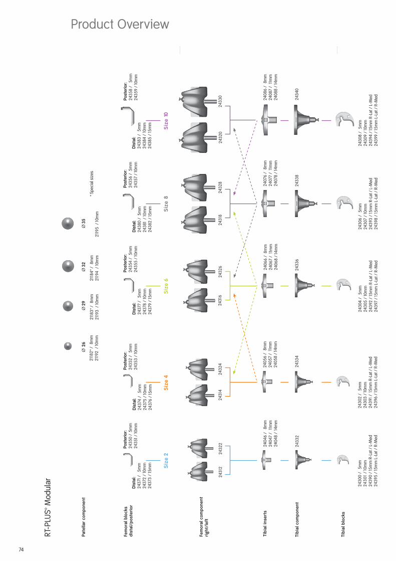
RT-PLUS™ Modular
Table of Contents
Introduction ........................................................................... 3
Concept/Description ............................................................. 4
Indications ............................................................................ 8
Contraindications .................................................................. 8
Case Study ............................................................................ 9
Preoperative Planning .......................................................... 10
Surgical Technique ............................................................... 13
Postoperative Treatment ......................................................51
References .......................................................................... 52
Sterilization ......................................................................... 53
Implants .............................................................................. 54
Instrumentation ................................................................... 60
Product Overview (Combination Tables) ...............................74
Nota Bene
The technique description herein is made available to the healthcare
professional to illustrate the authors’ suggested treatment for the
uncomplicated procedure. In the fi nal analysis, the preferred treatment
is that which addresses the needs of the patient.
1

2

With the rising number of implantations we are increasingly
being confronted by cases which are diffi cult to treat and
which require the use of special prosthetic systems using a
higher degree of coupling. The RT-PLUS™ Modular prosthesis
has been designed to take this development into account.
It is a constrained rotating knee, the development of which
drew upon knowledge and experience gained from state-of-
the-art knee joint prosthesis.
The RT-PLUS Modular knee system is the modular version of
RT-PLUS and it represents a valuable addition to bicondylar
surface replacement.
The functional design allows extremely sparing resections.
The joint components features anatomical geometry, as it’s
also used today for bicondylar surface replacement cases.
The femoral and tibial components have the same stem
coupling and are anchored in the bone by stems made of
Ti6Al
4V for cementless application and in CoCrMo for
cemented application. To compensate various femoral and/or
tibial bone defects, there are CoCrMo augmentation blocks
available.
Special attention was also paid to the development of a user-
friendly instrument set. This ensures that the prosthesis is
implanted securely and precisely.
3
Introduction

The RT-PLUS™ Modular is a constrained rotating knee prosthesis for cemented implantation.
The prosthesis allows an internal/external rotation of approx. 10° each. This is locked by the
tibial-insert when extended. Due to the peg design, the prosthesis has the capability
of elongation, i.e., for distraction between the femoral and the tibial components. In an ext-
reme fl exed position, the femoral component can lift off the tibial-insert, which reduces
the sagittal leverage forces that have an effect on the prosthesis stem in this load situation.
The implant allows sparing resections. The cut compatibility with the tricompartmental pros-
thesis TC-PLUS™ permits if necessary an intraoperative switchover from the resurfacing to
the constrained rotating knee.
The femoral and tibial components of RT-PLUS Modular are identical to those of RT-PLUS,
with the exception of the additional option to connect stems and augmentation blocks. The
tibial inserts are the same. As a result, the femoral and tibial components in both these
systems are entirely cross-compatible. All the stems of RT-PLUS Modular can be combined
with the femoral and tibial components of RT-PLUS Modular to suit requirements.
The implants are available in fi ve sizes (corresponding to RT-PLUS sizes 2, 4, 6, 8 and 10).
Apart from size 2, the sizes can be combined with the next size up or down.
Note
RT-PLUS Modular requires condylar support for the femoral/tibial components. The forces have to be absorbed by the condyles as well as by the stems.
4
Concept/Description

5
Femoral component
The femoral component is manufactured from
CoCrMo alloy and is asymmetrical.
The patellar groove is deeply hollowed out
and presents an anatomical oblique outline.
This feature offers improved patellar tracking
and leverage on the knee extensor appara-
tus.
The joint mechanism is contained in a narrow
box, the width of which is comparable to that
of a “posterior stabilized” implant. This allows
sparing bone resection, which reduces the
risk of femoral condyle fracture.
The rotation peg of 40 mm length provides
adequate security against dislocation, but
the components can nevertheless be easily
coupled. Because of the design of the con-
dyles, physiological “rollback” of 9 mm is
possible, which improves the fl exion capa-
bility of the joint.
The joint mechanism has been designed in such way that all metal components (peg and
joint axis) interface with UHMW polyethylene to absorb the stress forces therefore prevent-
ing premature wear.
A modular stem connection allows the use of different stems to stabilize the femoral
component.
To compensate femoral bone defects, distal and/or posterior femoral augmentation blocks
can be fi xed to the femoral component.
The femoral component is available in sizes 2, 4, 6, 8 and 10.
Please see the available sizes in the implant table (from page 54 ff).
Product Description

6
Patellar component
The all-poly (UHMW polyethylene) patellar
component has a symmetrical biconcave
surface for better tracking.
Tibial insert
The simple and securely anchored tibial insert
is manufactured from UHMW polyethylene and
is available in three different heights of 8 mm,
11 mm and 14 mm, in order to restore the joint
height independent to the degree of tibial
bone substance loss.
The special design of the polyethylene insert
enables an easy coupling of the prosthesis,
for which only minimal distraction is required.
The minimum effective PE thickness in the load zone is 8 mm. The selected manufacturing
method, the design (condyles) and the high-quality material combine to form the proven wear-
resistance of the insert.
The tibial inserts are identical to those in the RT-PLUS™ portfolio.
Tibial component
The symmetrical tibial component is manu-
factured from CoCrMo alloy.
In order to prevent polyethylene wear inside
the tibial component, the base plate is pol ished
on the inside and the insert is com pletely en-
closed along its entire circumference.
A modular stem connection allows the use of
different stems, which serve to stabilize the
tibial component.
To compensate tibial bone defects, proximal
tibial blocks can be fi xed on the tibial compo-
nent.
The tibial component is available in sizes 2,
4, 6, 8 and 10.

7
Femoral and tibial blocks
The femoral and tibial blocks are manufac-
tured from CoCrMo alloy.
In order to compensate different femoral and/
or tibial bone defects, there are distal femoral
blocks available in heights of 5 mm, 10 mm
and 15 mm, posterior femoral blocks in heights
of 5 mm and 10 mm and proximal tibial blocks
in heights of 5 mm, 10 mm and 15 mm.
The same femoral blocks are used for the
medial as for the lateral condyle of the
femoral component. The same tibial blocks,
except height of 15 mm, are used for the
medial as for the lateral condyle of the
tibial component.
The blocks have to be assembled to the femoral and tibial components with screws and can
then be cemented on the tibia, respectively on the femur.
Cemented stem
The femoral and tibial components can be
intramedullary anchored in the bone by
cemented conical stems, made of forged
CoCrMo alloy.
Available in lengths 95 mm, 120 mm and
160 mm.
Cementless stems
The femoral and tibial components can also be
stabilized into the bone by using non cement-
ed cylindrical stems, made of extruded Ti6Al
4V
alloy. These stems are not suitable for primary
anchorage; therefore, they are not designed for
osseointegration.
A wide stems range enables an optimum
adaptation to different indications. They are
available in various diameters (Ø 10, Ø 12,
Ø 14, Ø 16, Ø 18 and Ø 20 mm) and lengths
(95 mm, 120 mm, 160 mm and 200 mm) in order
to ensure optimum anchorage, even with a
variety of femoral or tibial geometries.
Please see the available sizes in the implant table (from page 54 ff).

8
The principal preoperative planning factor is the correct diagnosis. It has to be determined
whether the bone and stability situation require the implantation of a constrained prosthesis.
The main indications for implantation of RT-PLUS™ Modular are:
• High-grade joint destruction with considerable loss of function and requirement for addi-
tional stabilization with longer stems and reconstruction of bone defects
• Severe joint instability that predictably cannot be corrected by suitable bone reconstruction
(bone grafts) or soft-tissue intervention
• Marked contractures and axial displacements of more than 15°–20°
• Failure after surface replacement (e.g., infection, loosening) – revision of a primary prosthesis
• Trauma – induced femoral or tibial fractures
• Due to the design, it is possible to switch with relatively little effort, even intraoperatively,
from the TC-PLUS™ knee system to the RT-PLUS™ Modular knee system, since the resections
and prosthesis sizes are matching
Contraindications
Contraindications are:
• Acute or chronic, local or systemic infections (or in the case of a corresponding anamnesis)
• Severe muscle, nerve or vascular diseases that endanger the affected extremity
• Lacking bone substance or inadequate bone quality that endangers a stable seating of the
prosthesis
• Severe adiposity
• All concomitant diseases that may endanger the function of the implant. These include in
particular extreme insuffi ciency of the knee extensor mechanism, which can lead to exces-
sive joint distortion; or severe adiposity, which can lead to a dorsal impingement, which may
uncouple the components. In these cases it may be advisable to use a coupled hinge or a
tumour prosthesis
• Patient hypersensitivities or allergies to the materials used
• Strenuous physical activity (e.g., competitive sports, hard physical work)
See also instructions on the package insert.
Indications
9
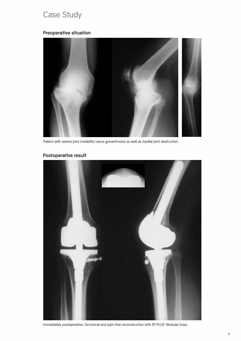
Preoperative situation
Case Study
Patient with severe joint instability (varus gonarthrosis) as well as medial joint destruction.
Postoperative result
Immediately postoperative; functional and pain-free reconstruction with RT-PLUS™ Modular knee.

10
A full-leg X-ray with the patient in the standing position is recommended for preoperative-
planning purposes. If this is not possible, an X-ray of the thigh, including the femoral head,
should be taken. The X-ray images of the knee joint at three levels should be available for
planning the surgery. A tangential patellar exposure, a frontal and a sagittal to the leg axis
exposure must be taken.
For preoperative planning there are X-ray tem-
plates available: with scale of 1.15:1 Lit. No. 1135
and with scale of 1:1 Lit. No. 1584 (see page
74). The lateral view of the condyles is deci-
sive. If these are no longer completely intact,
it is possible to switch to the condylar width.
In cases of doubt, the smaller implant should
be selected to prevent the prosthesis com-
ponents from protruding. In normal cases,
the size determination and the correct posi-
tioning of the prosthesis are controlled intra-
operatively with relevant instruments, and
planning may also be possible on the unre-
stored opposite side leg.
Note
The femoral and tibial component sizes can all be combined with the next size up or down (see product overview on page 76 ff). This does not apply to combinations of sizes 2 and 4.
Large deviations of the femoral-neck angle as
well as severe deformities of femur and tibia
(e.g., posttraumatic axial deformities) must be
taken into consideration during surgical plan-
ning.
In rare cases of deformities away from the knee
joint that negatively infl uence the mechanical
leg axis, additional corrective osteotomies may
be indicated.
Preoperative Planning

11
Planning of Surgery Using the Radiograph
A Anatomical femoral axis
B Anatomical tibial axis
C Mechanical leg axis
D Mechanical femoral axis
E Tibial resection depth (mm)� Valgus angle
Preop. Postop.
The following procedure is recommended for
the anterior-posterior whole leg imaging pro-
cess:
1. The femoral axis A (anatomical axis) is drawn
onto the radiograph.
2. A line is drawn from the femoral head to the
center of the knee (mechanical axis D) on the
radiograph.
3. The angle measured between the anatomical
and the mechanical axis = angle � determines
the valgus angle.
4. The tibial axis B is drawn in and the tibial re-
section plane E is determined to avoid exces-
sive resection, especially where there are
defects.
5. The component sizes and resection depths
are determined preoperatively using the
X-ray templates (Lit. No. 1135 or 1584) in A/P
and the lateral planes.
6. The mechanical leg axis C should merge with
lines D and B after correction.Postop.Preop.

12
13
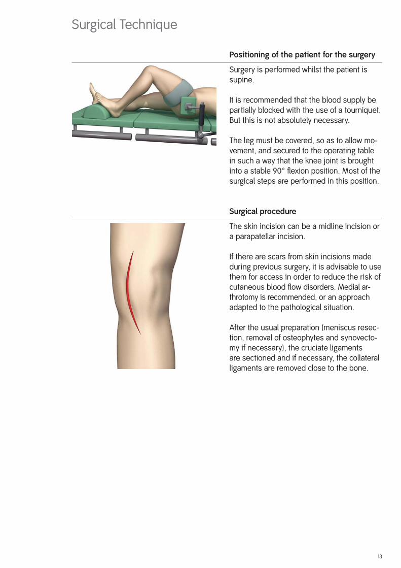
Positioning of the patient for the surgery
Surgery is performed whilst the patient is
supine.
It is recommended that the blood supply be
partially blocked with the use of a tourniquet.
But this is not absolutely necessary.
The leg must be covered, so as to allow mo-
vement, and secured to the operating table
in such a way that the knee joint is brought
into a stable 90° fl exion position. Most of the
surgical steps are performed in this position.
Surgical procedure
The skin incision can be a midline incision or
a parapatellar incision.
If there are scars from skin incisions made
during previous surgery, it is advisable to use
them for access in order to reduce the risk of
cutaneous blood fl ow disorders. Medial ar-
throtomy is recommended, or an approach
adapted to the pathological situation.
After the usual preparation (meniscus resec-
tion, removal of osteophytes and synovecto-
my if necessary), the cruciate ligaments
are sectioned and if necessary, the collateral
ligaments are removed close to the bone.
Surgical Technique

14
It is important that the fl exion and extension gaps are identical.
1. Distal femoral resection and optional distal
augment resection.
2. A/P femoral resections and optional posterior
augment resection.
3. Chamfer resections and cutting out of the
box. Remove residual posterior condyles if
present.
Note
To avoid the risk of a condyle fracture, werecommend to prepare the box after tibial preparation.
4. Tibial resection and optional augment
resection.
5. Patellar resection (optional).
Important
Only 1.0 mm saw blades must be used for all bone resections! See Lit. No. 1403 for corre-
sponding connection.
Overview of the Resections Sequences for Primary Application

15
The bone resections are refreshed after extraction of the primary implants.
1. Distal femoral resection and optional distal
augment resection.
2. A/P femoral resections and optional posterior
augment resection.
3. Chamfer resections and cutting out of the
box. Remove residual posterior condyles if
pre sent.
Note
To avoid the risk of a condyle fracture, werecommend to prepare the box after tibial preparation.
4. Tibial resection and optional augment
resection.
5. Patellar resection (optional).
Overview of the Resections Sequences for Revision Application

16
17
Access: Please refer to the relevant surgical textbooks for the initial access to the knee.
Note
In addition to the bone resections, it is important to correct any ligament imbalance by appropriate soft-tissue procedures. If necessary, a general release should be performed on the side of the contracture prior to the bone resections.
The leg is fl exed and any osteophytes on the femur and tibia should be removed. This
provides good exposure of the knee joint, which facilitates size determination.
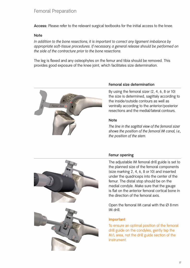
Femoral size determination
By using the femoral sizer (2, 4, 6, 8 or 10)
the size is determined, sagittaly according to
the inside/outside contours as well as
ventrally according to the anterior/posterior
resections and the medial/lateral contours.
Note
The line in the sagittal view of the femoral sizer shows the position of the femoral IM canal, i.e., the position of the stem.
Femur opening
The adjustable IM femoral drill guide is set to
the planned size of the femoral components
(size marking 2, 4, 6, 8 or 10) and inserted
under the quadriceps into the center of the
femur. The distal stop should be on the
medial condyle. Make sure that the gauge
is fl at on the anterior femoral cortical bone in
the direction of the femoral axis.
Open the femoral IM canal with the Ø 8 mm
IM drill.
Important
To ensure an optimal position of the femoral
drill guide on the condyles, gently tap the
M/L area, not the drill guide section of the
instrument.
Femoral Preparation

The Ø 8 mm IM rod is carefully inserted using
the modular handle to approximately the
isthmus of the femoral IM canal and removed
again. It is important to work carefully to pre-
vent excess pressure in the IM canal.
The femoral IM canal is opened further with
the Ø 8/14 mm stepped drill. Note that the
drill is positioned at the entry point of the
femoral IM canal, previously determinated by
the IM drill. The drill direction is along the
femoral axis. Drill as far as the stop.
Note
The femoral IM canal, which determines the implants stem position, must be opened carefully (reference for the femoral position) to prevent the development of a relative ex-tension position (risk of notching) or flexion position (projecting patella).
Preparing the femoral anchorage
Reamers are used carefully and in progres-
sive stages (starting with Ø 10) to ream to the
required stem diameter and depth.
Notes
Reamers are available in diameter Ø 10, Ø 12, Ø 14, Ø 16, Ø 18 and Ø 20. The depth indicator is on the reamer: observe the laser markings (95, 120, 160 and 200).
When using cemented stems, the Ø 12 mm reamer is used to drill to the desired depth and the corresponding cementless trial stem is used. The optional cemented trial stems are only used with the trial components (not with the instruments)!
The 200 mm length is only available in the cementless version.
18

19
Controlling the stem position
An extramedullary reamer alignment guide,
which is attached to the reamer, can be used
to check the position of the stem in axial
alignment and depth (the end of the reamer
alignment guide corresponds to the tip of the
reamer).
Preparing the femoral stem connection
If it is reamed only to diameters Ø 10, Ø 12 or
Ø 14, the stem connection recess has to be
reamed with the Ø 10/16 mm stepped reamer
until the laser marking (corresponding to the
resection level).
IM positioning and control with trial stems
The chosen trial stem is attached to the
extension for trial stem (Ø 8 mm) and with
the modular handle carefully inserted into the
femoral IM canal so the line marked with
PRIMARY respectively REV. is approximately
level to the distal bone resection. The modu-
lar handle is now removed. It is important to
avoid putting excessive pressure in the femo-
ral IM canal.
Note
With too short IM guidance, the alignment may be incorrect (varus/valgus, extension/flexion).

20
Locating the distal femoral cutting block
The 6° femoral bushing corresponds to the angle �
determined in the preoperative planning. The femoral
bushing is inserted into the femoral suspension device,
so that depending on which side is the operation, the
mark L for left knee or R for right knee is visible on the
arrow ▼.
Note
Make sure that the femoral bushing is inserted in the correct (L or R) position. Adjustment and correction occurs with removing, rotating by 180° and reinserting the femoral bushing.
The femoral/tibial revision cutting block is screwed to the femoral suspension device and
positioned over the trial stem extension (Ø 8 mm). The handles can be attached.
NoteIn revision cases, the 7 mm distal revision spacer for femoral condyle is attached to the femoral suspension device (black plastic component in picture). This substitutes the missing distal bone substance. The resulting resection remains still 2 mm.
Align the device with regard to rotation. Note that the
removable handles are parallel to the epicondylar axis.
After preliminary drilling with the Ø 3.2 mm drill, from
distal the femoral suspension device is fi xed with a
bone pin (75 mm long).
After preliminary drilling with the Ø 3.2 mm drill, the
femoral/tibial revision cutting block is fi xed with two
bone pins (75 mm long) through the holes marked 0.
This position resects 9 mm from the distal femur, which
corresponds to the distal thickness of the femoral
prosthesis without femoral blocks.
ImportantFor preventing any confl ict with the trial stem, the most lateral 0 pin hole of the femoral /
tibial revision cutting block is preferred.
The bone pin on the femoral suspension device is removed with a pin extractor. After loosening
the fi xation screw, the trial stem with extension (Ø 8 mm) is removed using the modular handle.
The suspension device is now removed.
Notes
The resection depth can be adjusted proximally and distally in 2 mm increments (±4 mm).
The side handles can be removed from the femoral suspension device and attached on the femoral/tibial revision cutting block.
21
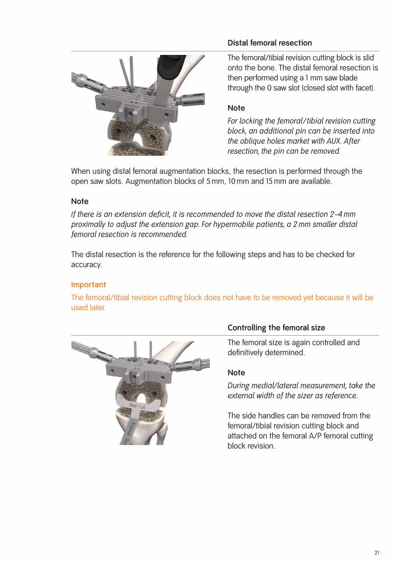
Distal femoral resection
The femoral/tibial revision cutting block is slid
onto the bone. The distal femoral resection is
then performed using a 1 mm saw blade
through the 0 saw slot (closed slot with facet).
Note
For locking the femoral /tibial revision cutting block, an additional pin can be inserted into the oblique holes market with AUX. After resection, the pin can be removed.
When using distal femoral augmentation blocks, the resection is performed through the
open saw slots. Augmentation blocks of 5 mm, 10 mm and 15 mm are available.
Note
If there is an extension deficit, it is recommended to move the distal resection 2–4 mm proximally to adjust the extension gap. For hypermobile patients, a 2 mm smaller distal femoral resection is recommended.
The distal resection is the reference for the following steps and has to be checked for
accuracy.
Important
The femoral/tibial revision cutting block does not have to be removed yet because it will be
used later.
Controlling the femoral size
The femoral size is again controlled and
defi nitively determined.
Note
During medial/lateral measurement, take the external width of the sizer as reference.
The side handles can be removed from the
femoral/tibial revision cutting block and
attached on the femoral A/P femoral cutting
block revision.

Locating the A/P femoral cutting block
The chosen trial stem is attached to the exten-
sion for trial stem (Ø 8 mm) and inserted into
the femoral IM canal. The A/P femoral cutting
block revision is placed on top.
Note
When using distal femoral augmentation blocks, the corresponding blocks must be fixed on the A/P femoral cutting block revision. Respect the thickness (5 mm, 10 mm or 15 mm) and size (2, 4 or 6, 8, 10).
The rotation of the A/P femoral cutting block
revision is adjusted by applying anteriorly the
femoral/tibial revision cutting block.
Note
If the rotation of the A/P femoral cutting block revision has to be readjusted, the rotation is set visually in relation to the epicondylar axis with aid of the side attached handles.
After preliminary drilling with the Ø 3.2 mm
drill, the A/P femoral cutting block revision is
fi xed with two bone pins (38 mm with head)
through the lateral 45° oblique holes.
Checking the resections
With the resection stylus, the anterior and
posterior resection plane and height are
checked.
22

23
A/P and chamfer resections
The anterior femoral resection is made
through the closed saw slot with the 1 mm
saw blade (anterior slot with facet).
The posterior femoral resection is made
through the two open posterior saw slots
(slots with facet).
When using posterior femoral augmentation
blocks, the resection is made through the
open 5 mm and 10 mm saw slots.
The femoral chamfer resections are made
through the corresponding slots (slots with
facet).

24
Preparing the femoral box (IM)
Note
In order to improve support for the Hohman, we recommend preparing the femoral box after tibial preparation.
Important
This application is performed when bone tissue
is not available to ensure good instrument
support (especially in the anterior bone area
and after explantation of a prosthesis). In
case of good distal and anterior bone sup-
port, the EM femoral box preparation is pre-
ferred (see page 29).
The A/P femoral cutting block revision is
removed and the femoral resections can be
checked.
Slide the trial stem already used with the trial
stem extension (Ø 8 mm) into the femoral IM
canal again using the modular handle and now
detach the modular handle.
Slide the box saw guide IM positioning device
(size 2 or sizes 4–10) onto the extension up
to the distal cut with the box saw guide po-
sitioner (observe size). It is important for the
box saw guide to be fl ush with the cut
surfaces.
Note
When using distal femoral blocks, mount the appropriate blocks on the femoral cutting block. Observe the appropriate thickness (5 mm, 10 mm or 15 mm).
The side handles can be attached to the box
saw guide positioning device.
Note
If required (absent anterior bone tissue) ad-just rotation with the aid of the side handles, reference to the femoral epicondyle.

25
Fix the box saw guide IM positioning device
with pins with head (38 mm) through the dis-
tal holes.
Together with the trial stem and the trial stem
extension, withdraw the box saw guide
positioner using the trial stem handle, which
is attached to the trial stem extension.
The IM box saw guide (guide for size 2 and
sizes 4–10) can be slid in the positioning
device.
Perform the cuts with a special 13 mm wide
saw blade, which is introduced up to the
RT 45 mark.
Note
Protect vessels and nerves in the popliteal fossa.
Remove all the pins, the IM box saw guide
and the positioning device.

26
Excavate the femoral box with a thin, straight
osteotome and a luer along the outer limits
marked and prepared with the saw blade
(with the osteotome, the two lateral box cuts
are carefully posteriorely extended).
From anterior into the IM canal hole, the
narrow saw blade (or an osteotome) is intro-
duced for cutting the posterior cortical box
bone.
Important
To protect the important posterior soft tissues,
a Hohman is placed centered onto the
posterior condyle.
Cut off the upper bone edge to provide space
for the rounding from the patellar shield to
the box wall.
Note
Helpfully a “cross” can be prepared with the saw for removing the femoral box. The re-maining triangle bone is finally removed by using a luer.
27
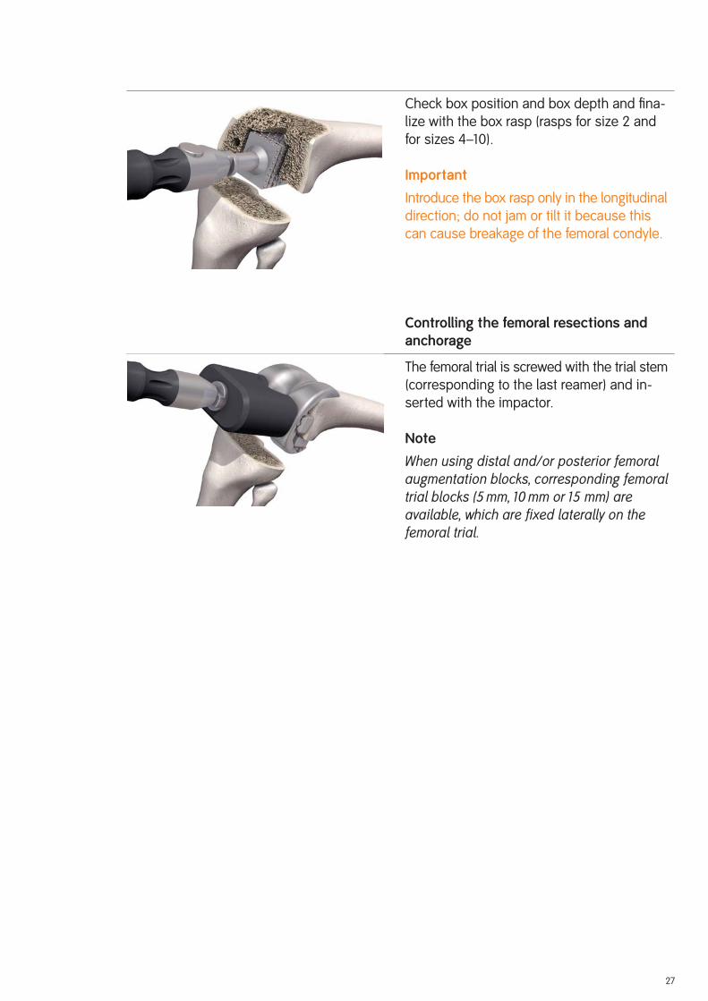
Check box position and box depth and fi na-
lize with the box rasp (rasps for size 2 and
for sizes 4–10).
Important
Introduce the box rasp only in the longitudinal
direction; do not jam or tilt it because this
can cause breakage of the femoral condyle.
Controlling the femoral resections and anchorage
The femoral trial is screwed with the trial stem
(corresponding to the last reamer) and in-
serted with the impactor.
Note
When using distal and/or posterior femoral augmentation blocks, corresponding femoral trial blocks (5 mm, 10 mm or 15 mm) are available, which are fixed laterally on the femoral trial.
28
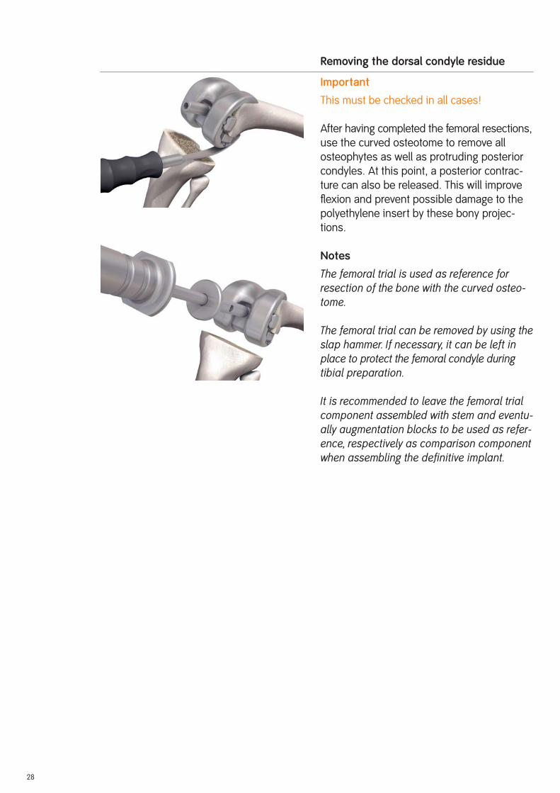
Removing the dorsal condyle residue
Important
This must be checked in all cases!
After having completed the femoral resections,
use the curved osteotome to remove all
osteophytes as well as protruding posterior
condyles. At this point, a posterior contrac-
ture can also be released. This will improve
fl exion and prevent possible damage to the
polyethylene insert by these bony projec-
tions.
Notes
The femoral trial is used as reference for re section of the bone with the curved osteo-tome.
The femoral trial can be removed by using the slap hammer. If necessary, it can be left in place to protect the femoral condyle during tibial preparation.
It is recommended to leave the femoral trial component assembled with stem and eventu-ally augmentation blocks to be used as refer-ence, respectively as comparison component when assembling the definitive implant.

29
If bone tissue is distally and anteriorly available to ensure good instrument support,
the “EM femoral box processing” version can be proceeded (this version is faster and easier
in handling).
EM preparation of the femoral box
Note
In order to improve support for the Hohman, we recommend preparing the femoral box after tibial preparation.
Important
For this application, anterior bone substance
has to be available!
To position medio-laterally the femoral box saw
guide, respectively the femoral component,
use the centering template, which is inserted
through the anterior saw slot of the A/P
femoral revision cutting block in regard to the
femoral size, to make a mark (e.g., with an
electrocauter or a pin) on the anterior cortical
bone.
On the anterior cortical bone marking, the
femoral box saw guide (guides for size 2 and
sizes 4–10) is aligned and fi xed with bone
pins.
It is important that the box saw guide is fl ush
with the resections.
Note
When using distal femoral augmentation blocks the corresponding blocks must be fixed on the box saw guide. Respect the thickness (5 mm, 10 mm or 15 mm).
The side handles can be attached on the box
saw guide.
EM Femoral Box Preparation Option

30
The resections are performed using a special
13 mm wide saw blade.
The saw blade is inserted up to the RT 45
mark.
Note
Protect the vessels and nerves in the popliteal fossa.
In the case of the guide for sizes 4–10, make
the anterior box cut in the saw slot of the re-
spective size.
Following, the box saw guide is removed.
The next cuts can be found on page 24 ff.

31
The leg is fl exed and any remaining osteophytes and the intercondylar eminence are removed.
Tibia opening
Open the tibial IM canal with the Ø 8/14 mm
stepped drill.
Position the hole centrally M/L and one third
from anterior.
Preparing the tibial anchorage
Reamers are used carefully and in progressive
stages (starting with Ø 10) to ream to the re-
quired stem diameter and depth.
Notes
Reamers are available in diameter Ø 10, Ø 12, Ø 14, Ø 16, Ø 18 and Ø 20. The depth indicator is on the reamer: observe the laser markings (95, 120, 160 and 200).
When using cemented stems, the Ø 12 mm reamer is used to drill to the desired depth and the corresponding cementless trial stem is used. Cemented stems are available in 95 mm, 120 mm and 160 mm lengths. The opti-onal cemented trial stems are only used with the trial components (not with the instru-ments)!
The 200 mm length is only available in the cementless version.
Tibial Preparation

32
Controlling the stem position
An extramedullary reamer alignment guide,
which is attached to the reamer, can be used
to check the position of the stem in axial
alignment and depth (the end of the reamer
alignment guide corresponds to the tip of the
reamer).
Preparing the tibial stem connection
If it is reamed only to diameters Ø 10, Ø 12
or Ø 14, the stem connection recess has
to be reamed with the Ø 10/16 mm stepped
reamer until the laser marking (corresponding
to the resection level).
IM positioning and control with trial stems
The chosen trial stem is attached to the ex-
tension for trial stem (Ø 8 mm) and with the
modular handle carefully inserted into the tibial
IM canal so the line marked with PRIMARY
respectively REV. is approximately level to
the proximal bone resection. The modular
handle is now removed. It is important to avoid
putting excessive pressure in the tibial IM
canal.
Note
With too short IM guidance, the alignment may be incorrect (varus/valgus, extension/flexion).

33
Locating the tibial cutting block
The two tibial resection guide IM components
are coupled together by jointing arrow to
arrow and pressing the button.
The femoral/tibial revision cutting block is
attached to the tibial resection guide IM with
the top small grub screw and slid completely
onto the trial stem extension (Ø 8 mm).
Note
Ensure the lock lever is set to OPEN to slide in place the tibial resection guide IM. The lock lever is then reversed to fix the tibial re section guide IM in place.
The femoral/tibial revision cutting block is
fi rst lifted upwards by pressing the button so
the tibial stylus can be attached.
Setting the resection height
The tibial stylus is positioned on the tibial
plateau. The tibial stylus can be used for both
primary resections (11 mm marking) and for
revision resections (1 mm marking).
Notes
In primary revision procedures, the 11 mm tibial stylus is positioned on the lowest point of the less-damaged condyle.
In revision procedures where no tibial aug-mentation blocks are required the 1 mm tibial stylus is positioned on the lowest area of the tibial plateau.
In revision procedures where augmentation blocks are required, 1 mm tibial stylus is positioned on the lowest point of the less-damaged condyle.
34
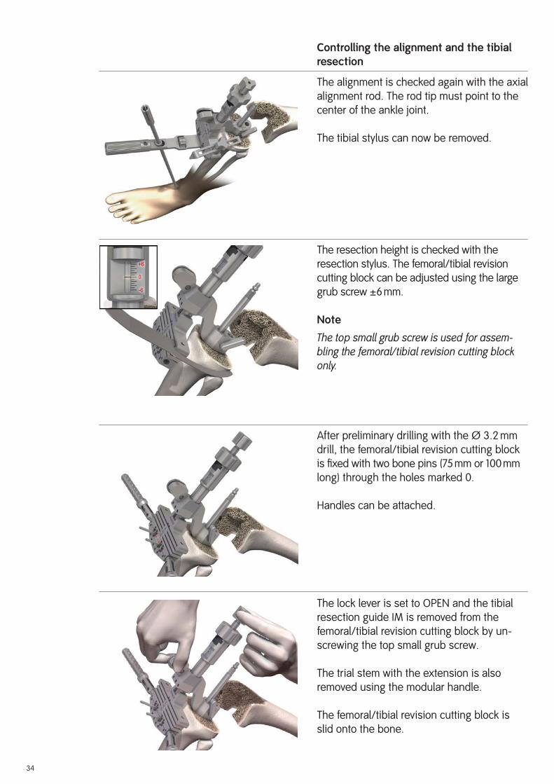
Controlling the alignment and the tibial resection
The alignment is checked again with the axial
alignment rod. The rod tip must point to the
center of the ankle joint.
The tibial stylus can now be removed.
The resection height is checked with the
resection stylus. The femoral/tibial revision
cutting block can be adjusted using the large
grub screw ±6 mm.
Note
The top small grub screw is used for assem-bling the femoral/tibial revision cutting block only.
After preliminary drilling with the Ø 3.2 mm
drill, the femoral/tibial revision cutting block
is fi xed with two bone pins (75 mm or 100 mm
long) through the holes marked 0.
Handles can be attached.
The lock lever is set to OPEN and the tibial
resection guide IM is removed from the
femoral/tibial revision cutting block by un-
screwing the top small grub screw.
The trial stem with the extension is also
removed using the modular handle.
The femoral/tibial revision cutting block is
slid onto the bone.
35
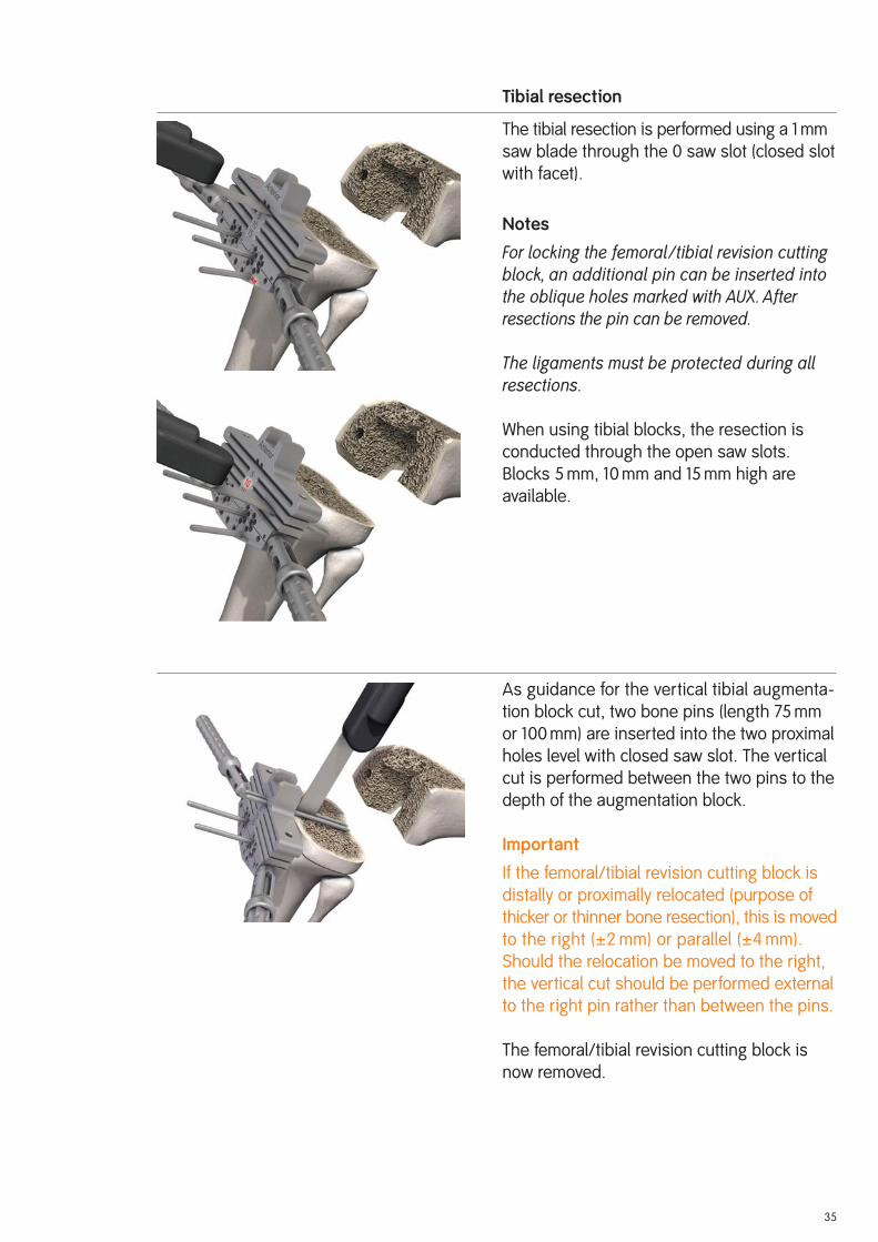
Tibial resection
The tibial resection is performed using a 1 mm
saw blade through the 0 saw slot (closed slot
with facet).
Notes
For locking the femoral /tibial revision cutting block, an additional pin can be inserted into the oblique holes marked with AUX. After resections the pin can be removed.
The ligaments must be protected during all resections.
When using tibial blocks, the resection is
conducted through the open saw slots.
Blocks 5 mm, 10 mm and 15 mm high are
available.
As guidance for the vertical tibial augmenta-
tion block cut, two bone pins (length 75 mm
or 100 mm) are inserted into the two proximal
holes level with closed saw slot. The vertical
cut is performed between the two pins to the
depth of the augmentation block.
Important
If the femoral/tibial revision cutting block is
distally or proximally relocated (purpose of
thicker or thinner bone resection), this is moved
to the right (±2 mm) or parallel (±4 mm).
Should the relocation be moved to the right,
the vertical cut should be performed external
to the right pin rather than between the pins.
The femoral/tibial revision cutting block is
now removed.
36
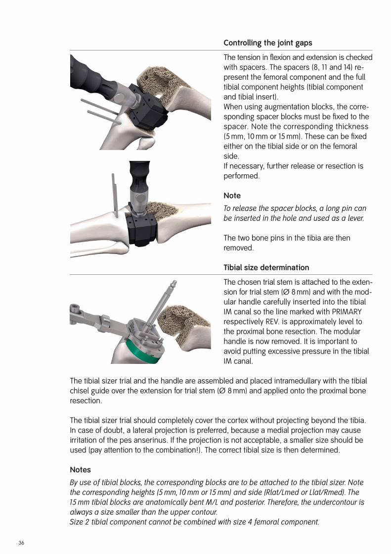
Controlling the joint gaps
The tension in fl exion and extension is checked
with spacers. The spacers (8, 11 and 14) re-
present the femoral component and the full
tibial component heights (tibial component
and tibial insert).
When using augmentation blocks, the corre-
sponding spacer blocks must be fi xed to the
spacer. Note the corresponding thickness
(5 mm, 10 mm or 15 mm). These can be fi xed
either on the tibial side or on the femoral
side.
If necessary, further release or resection is
performed.
Note
To release the spacer blocks, a long pin can be inserted in the hole and used as a lever.
The two bone pins in the tibia are then
removed.
Tibial size determination
The chosen trial stem is attached to the exten-
sion for trial stem (Ø 8 mm) and with the mod-
ular handle carefully inserted into the tibial
IM canal so the line marked with PRIMARY
respectively REV. is approximately level to
the proximal bone resection. The modular
handle is now removed. It is important to
avoid putting excessive pressure in the tibial
IM canal.
The tibial sizer trial and the handle are assembled and placed intramedullary with the tibial
chisel guide over the extension for trial stem (Ø 8 mm) and applied onto the proximal bone
resection.
The tibial sizer trial should completely cover the cortex without projecting beyond the tibia.
In case of doubt, a lateral projection is preferred, because a medial projection may cause
irritation of the pes anserinus. If the projection is not acceptable, a smaller size should be
used (pay attention to the combination!). The correct tibial size is then determined.
Notes
By use of tibial blocks, the corresponding blocks are to be attached to the tibial sizer. Note the corresponding heights (5 mm, 10 mm or 15 mm) and side (Rlat/Lmed or Llat/Rmed). The 15 mm tibial blocks are anatomically bent M/L and posterior. Therefore, the undercontour is always a size smaller than the upper contour.Size 2 tibial component cannot be combined with size 4 femoral component.

Setting the tibial rotation
The tibial rotation is determined anatomically
statically (orientation to the tibial tuberosity,
and the axial alignment rod tip must point to
the center of the ankle joint).
After preliminary drilling with the Ø 3.2 mm
drill, the tibial sizer is fi xed with at least two
bone pins with head.
Remove the chisel guide and the trial stem
and refi t the chisel guide.
Note
Positioning of the chisel guide is achieved by introducing and rotating the chisel guide clockwise in the tibial sizer. If insertion or re-moval proves difficult, a long pin can be used as a lever, which is placed in the anterior hole of the chisel guide.
37

38
Preparing the tibial IM canal
Prepare the proximal tibial anchorage with the osteotome
and the rasp.
By using the thin narrow 10 mm chisel, the tibial cavity is pre-
liminary prepared along the internal tibial chisel guide con-
tour. This in oder to avoid bone fractures, especially with bad
bone quality. The chisel must be fl ush with the tibial chisel
guide.
Now remove the tibial chisel guide.
Notes
If sclerotic bone, the fins are especially important to be pre-pared! They can as well be used a reference for the tibial rotation positing.
In order to prepare the tibial trial, we recommend screwing the trial stem onto the tibial trial at this point.
With the tibial rasp, the proximal tibial cavity is defi nitively
prepared. The rasp must be knocked in far enough to ensure
that the top of the rasp is fl ush with the (more proximal) bone
resection (or fl ush with the height of the lower plane of the
tibial sizer).
Notes
In order to avoid bone fractures, knock the rasp in carefully.
In order to protect the rasp sharp threats, perform rasping with-out the tibial sizer if necessary. In this case, with a thin chisel or by using an electro-cauter, the tibial anchorage fins positions are mark on the bone in order to guide the rasp.
If both side tibial augmentation blocks are planned, it is un-necessary to rasp down to the resection level. The rasp must be knocked down so far that the 5mm, 10mm or 15mm line marked on the rasp corresponds to the bone resections.

Trial reduction
The purpose of the trial reduction is to check
the radius of movement, patella guidance
and the tension of the soft-tissue mechanism.
The tibial trial together with the trial stem
(depending on the last reamer diameter and
depth) are inserted with using the impactor.
Note
It is possible that the same trial stem is re-quired on the femur and on the tibia. In this case, for the femoral trial fit a shorter trial stem with the same diameter or one of equal length with a smaller diameter or do not fit a trial stem at all.
The femoral trial together with the trial stem
(depending on the last reamer diameter and
depth) are inserted with using the impactor.
Note
When using blocks, there are appropriate block trials available (5 mm, 10 mm and 15 mm), which are fixed to the tibial trial or femoral trial.
Attach the appropriate tibial insert trial, which
has been previously defi ned with the spacer,
onto the rotation peg of the femoral trial in
the 90° fl exed position and insert it into the
tibial trial by hand.
The implant fi t, the kinematics of the knee
joint, and patellar function are checked.
At this point, a defi nitive decision should be taken regarding patella replacement (see instructions on page 41 ff).
39

40
When the defi nitive implants have been selected, make the components ready for assembly (see instructions on page 43 ff).
Remove the trial components with the slap
hammer, starting with the femur.
Note
As reference, it is recommended to leave as-sembled the trial components with stem and eventual blocks. They are used for controlling, respectively as comparison with the definitive implant.
The leg is extended. Soft tissue on the posterior surface of the patella is exposed preserving
the ligaments.
If the posterior surface of the patella is not replaced, the patella is freed from osteo-phytes and denerved.
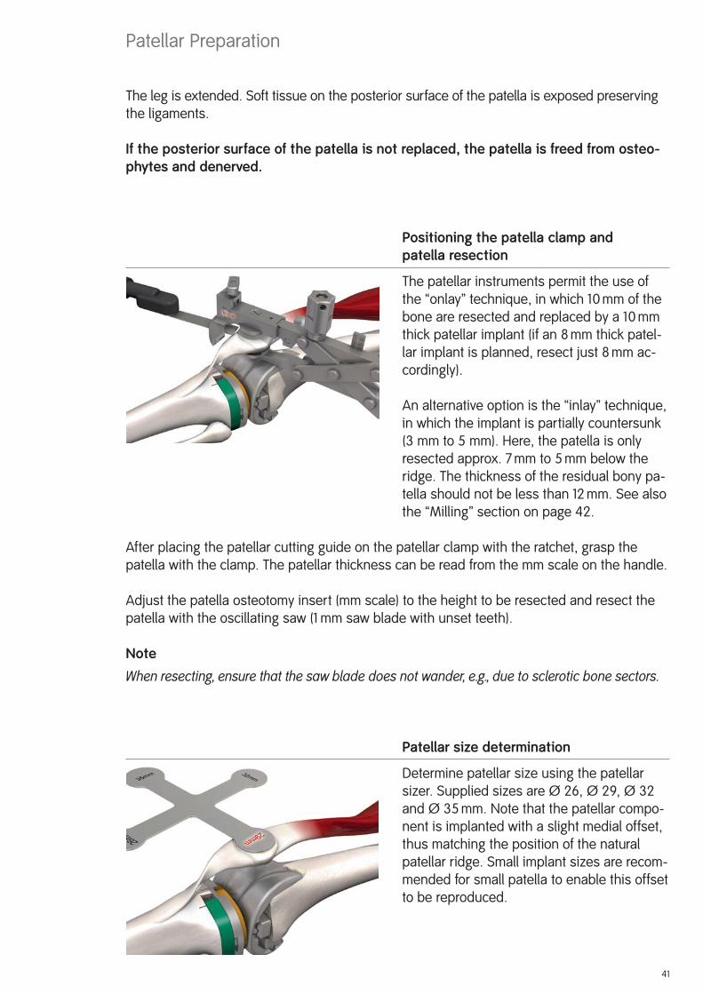
Positioning the patella clamp and patella resection
The patellar instruments permit the use of
the “onlay” technique, in which 10 mm of the
bone are resected and replaced by a 10 mm
thick patellar implant (if an 8 mm thick patel-
lar implant is planned, resect just 8 mm ac-
cordingly).
An alternative option is the “inlay” technique,
in which the implant is partially countersunk
(3 mm to 5 mm). Here, the patella is only
resected approx. 7 mm to 5 mm below the
ridge. The thickness of the residual bony pa-
tella should not be less than 12 mm. See also
the “Milling” section on page 42.
After placing the patellar cutting guide on the patellar clamp with the ratchet, grasp the
patella with the clamp. The patellar thickness can be read from the mm scale on the handle.
Adjust the patella osteotomy insert (mm scale) to the height to be resected and resect the
patella with the oscillating saw (1 mm saw blade with unset teeth).
Note
When resecting, ensure that the saw blade does not wander, e.g., due to sclerotic bone sectors.
Patellar size determination
Determine patellar size using the patellar
sizer. Supplied sizes are Ø 26, Ø 29, Ø 32
and Ø 35 mm. Note that the patellar compo-
nent is implanted with a slight medial offset,
thus matching the position of the natural
patellar ridge. Small implant sizes are recom-
mended for small patella to enable this offset
to be reproduced.
41
Patellar Preparation

42
Milling
Mount the patellar bushing onto the patellar
clamp with the ratchet.
Select the patellar reamer to match the corres-
ponding patella size. Depending on the select-
ed anchoraging technique, mill briefl y (“onlay”
technique) or countersink by 3 mm to 5 mm
(“inlay” technique ). Milling down to the stop
results in a depth of 5 mm.
Note
Patellar implants with a height of 10 mm are recommended as standard. Implants with a height of 8 mm are available as an alternative for thin patella.
Drill anchoring holes
Using the patellar drill guide and the patellar
drill with stop, prepare the anchoring holes
for the pegs.
Trial reduction
Patellar trials are available for trial reduction.

43
The assembling block is essential for safe and gentle assembling of the implants.
Note
When assembling the implant component, always start with the stem first. Then the blocks can be fixed. Otherwise the block screw may come loose during impacting.
Important
Be aware: if any screw or clamp is missing from the respective component or for any reason
is not sterile, a set of replacement screws and clamps (page 57) is available.
Assembling the tibial component
The tibial component (page 54) is positioned
in the specifi ed position on the assembling
block.
The stem (page 58) is inserted into the taper.
It is recommended to turn the stem so that
the security screw is positioned medially
(lower stress in this zone), and that no fi n but
a groove is anteriorly positioned (thereby a
larger surface is in contact with the internal
cortical bone).
Important
Pay attention that the tapered connection is
undamaged, clean and dry before mounting
and when using cementless stems that a
pocket is anterior, not a rib.
Fixing the stem (cemented/cementless) to the tibial component
The prepared automatic hammer with adap-
tor is placed on the stem. The stem is se-
curely attached to the tibial component by
impacting the stem three times.
Notes
When using 200 mm stems, place the cross-shaped stem protector into the adaptor for automatic hammer.
A stem connection with 3° posterior slope is integrated into the tibial component.
Assembling the Implants – Components
44
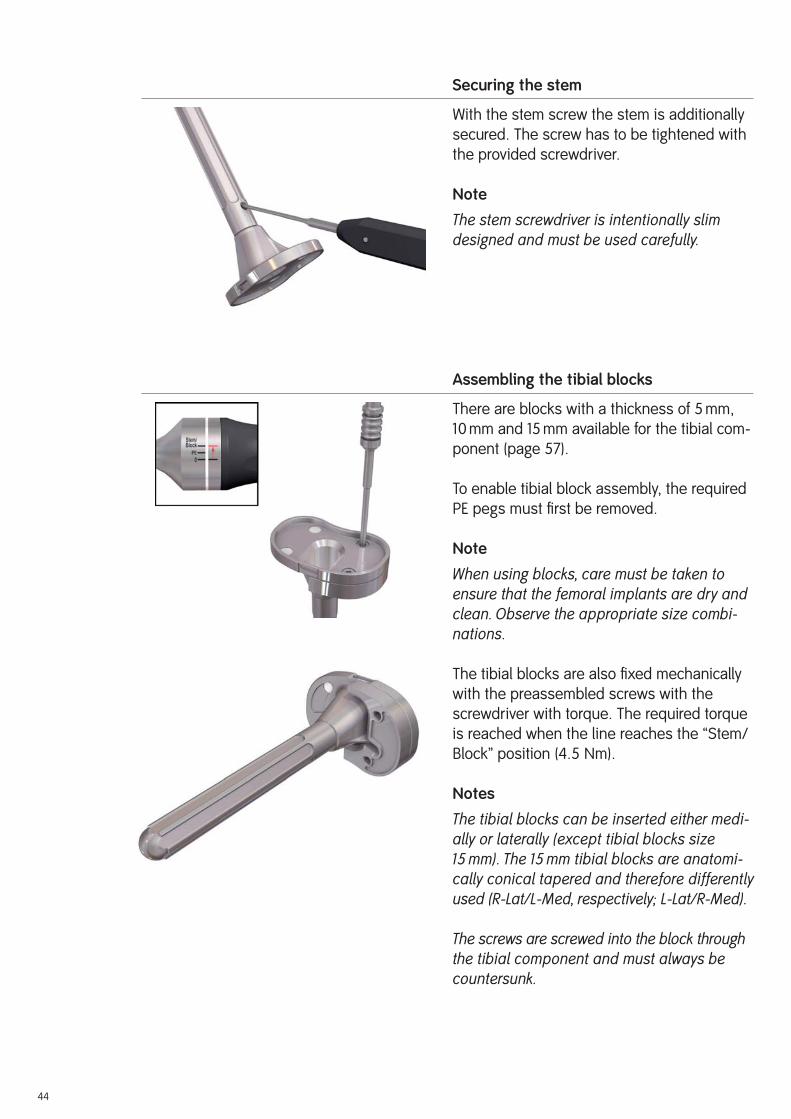
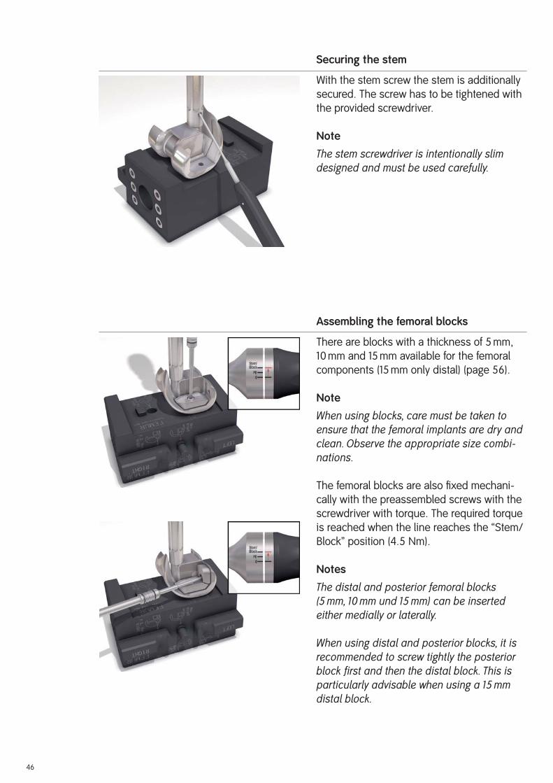
Securing the stem
With the stem screw the stem is additionally
secured. The screw has to be tightened with
the provided screwdriver.
Note
The stem screwdriver is intentionally slim designed and must be used carefully.
Assembling the tibial blocks
There are blocks with a thickness of 5 mm,
10 mm and 15 mm available for the tibial com-
ponent (page 57).
To enable tibial block assembly, the required
PE pegs must fi rst be removed.
Note
When using blocks, care must be taken to ensure that the femoral implants are dry and clean. Observe the appropriate size combi-nations.
The tibial blocks are also fi xed mechanically
with the preassembled screws with the
screwdriver with torque. The required torque
is reached when the line reaches the “Stem/
Block” position (4.5 Nm).
Notes
The tibial blocks can be inserted either medi-ally or laterally (except tibial blocks size 15 mm). The 15 mm tibial blocks are anatomi-cally conical tapered and therefore differently used (R-Lat/L-Med, respectively; L-Lat/R-Med).
The screws are screwed into the block through the tibial component and must always be countersunk.

45
Assembling the femoral component
The femoral component (page 54) is posi-
tioned in the specifi ed position on the
assembling block.
Fixing the stem (cementless) to the femo-ral component
The stem (page 58) is inserted into the taper.
It is recommended to turn the stem so that
the security screw is positioned medially
(lower stress in this zone, and in addition will
facilitate the screwing later on), and that no
fi n but a groove is anteriorly positioned
(thereby a larger surface is in contact with
the internal cortical bone).
Important
Pay attention that the tapered connection is
undamaged, clean and dry before mounting
and by using cementless stems that a pocket
is anterior, not a rib.
The prepared automatic hammer with adap-
tor is placed on the stem. The stem is se-
curely attached to the femoral component by
impacting the stem three times.
Notes
When using 200 mm stems, place the cross-shaped stem protector into the adaptor for automatic hammer.
A stem connection with 6° valgus angle is integrated into the femoral component.
46
Securing the stem
With the stem screw the stem is additionally
secured. The screw has to be tightened with
the provided screwdriver.
Note
The stem screwdriver is intentionally slim designed and must be used carefully.
Assembling the femoral blocks
There are blocks with a thickness of 5 mm,
10 mm and 15 mm available for the femoral
components (15 mm only distal) (page 56).
Note
When using blocks, care must be taken to ensure that the femoral implants are dry and clean. Observe the appropriate size combi-nations.
The femoral blocks are also fi xed mechani-
cally with the preassembled screws with the
screwdriver with torque. The required torque
is reached when the line reaches the “Stem/
Block” position (4.5 Nm).
Notes
The distal and posterior femoral blocks (5 mm, 10 mm und 15 mm) can be inserted either medially or laterally.
When using distal and posterior blocks, it is recommended to screw tightly the posterior block first and then the distal block. This is particularly advisable when using a 15 mm distal block.

47
Mix the bone cement according to the respective manufacturer’s instructions. Clean, wash
and dry the bone bed suffi ciently. Modern cementing techniques using a vacuum mixer and
jet lavage are recommended.
The RT-PLUS™ Modular knee is used with cement, with the exception of cementless stems. First
cement the tibial component and then the femoral component.
Note
With sclerotic bone it is recommended to drill several holes using a Ø 3.2 mm drill. This improves anchorage between the bone cement and the bone.
Ti6Al4V stems: The backs of the condyles and the box walls of the femoral component are
coated with cement. The back of the tibial component is coated with cement (back of plateau
and box). The Ti6Al
4V stems are not cemented.
Important
When implanting Ti6Al
4V stems, pay attention that the rotation alignments of the femoral
and tibial components correspond already when the stems are inserted to the defi nitive
implant positions. This prevents unnecessary rib notches occurring in the IM canal.
CoCr stems: The medullary plugs are accordingly placed deeper than the components. It is
recommended to fi ll up the IM canals using a cement gun.
Implanting the tibial and femoral components
In 90° fl exed position, the tibial component is
hammered using the corresponding impactor.
Excess cement is carefully removed. While
the cement is setting, the implant components
must be under continuous pressure.
Note
Make sure that cement is applied between the fin connection and stem connection when using tibial blocks.
Implanting the Components

48
The femoral component is hammered using
the impactor. Here, too, continuous pressure
must be maintained and excess cement
removed.
Important
Make sure that the posterior femoral condyles
do not come into contact with the tibial com-
ponent when impacting the femoral component.
We recommend covering the tibial component
with a compress.
Before the femoral component cement has set,
the plastic lug that protects the box against the
entry of cement must be removed.
Last controlling
Prior to defi nitive assembly of the tibial insert
it is possible to use the tibial insert trial for a
fi nal trial reduction.
Before the cement has set, the excess cement
must be removed in extension.
Insertion of the tibial insert
The tibial insert of the corresponding size
(see page 55) may only be inserted when the
cement has fully hardened.
In 90° fl exed position, the tibial insert is placed
on the femoral component rotation peg and
slid into the tibial component by hand.
Important
Note the correct anatomical alignment. It is
important to make sure that no soft tissue
is coming between the tibial insert and the
tibial component.
Note
In order to prevent the anterior metal clamp from falling out, handle the tibial insert care-fully.
49
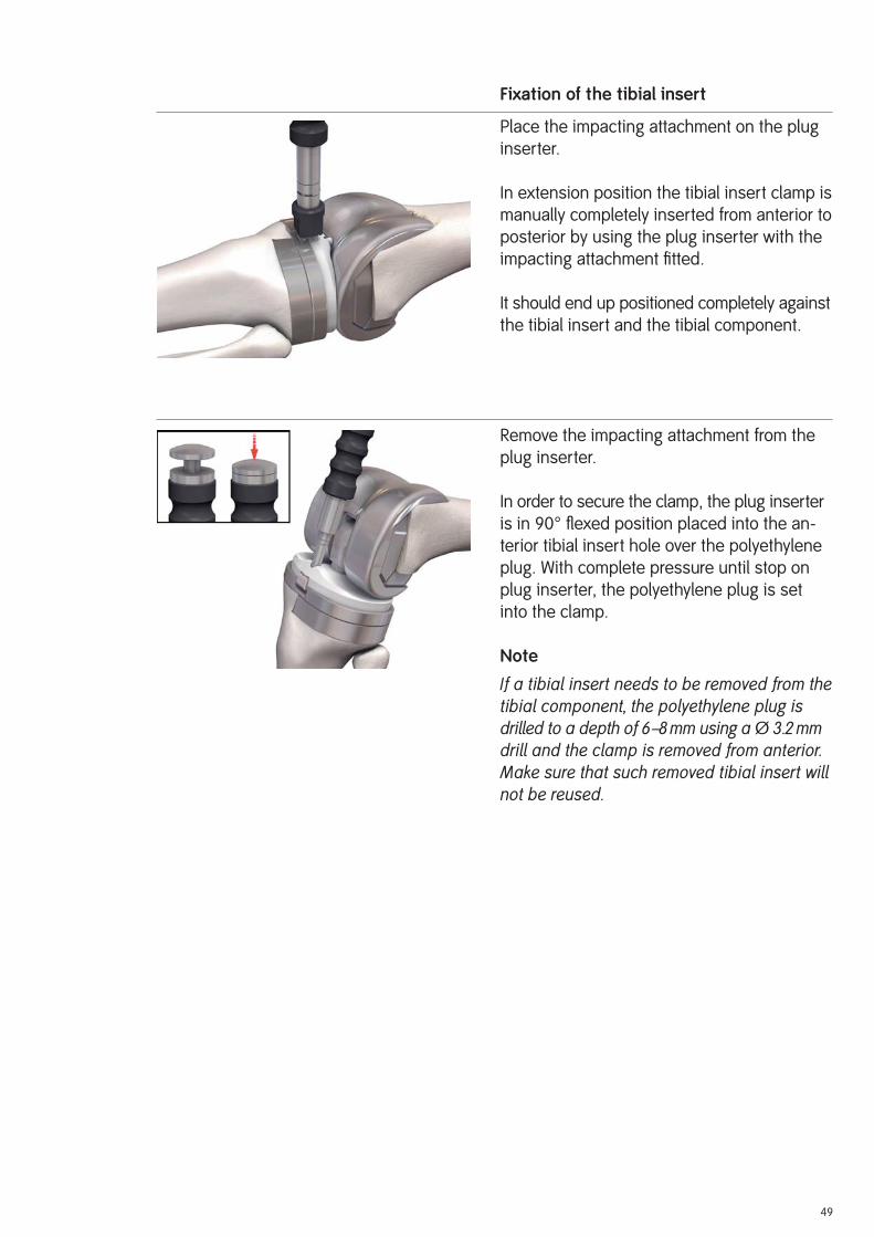
Fixation of the tibial insert
Place the impacting attachment on the plug
inserter.
In extension position the tibial insert clamp is
manually completely inserted from anterior to
posterior by using the plug inserter with the
impacting attachment fi tted.
It should end up positioned completely against
the tibial insert and the tibial component.
Remove the impacting attachment from the
plug inserter.
In order to secure the clamp, the plug inserter
is in 90° fl exed position placed into the an-
terior tibial insert hole over the polyethylene
plug. With complete pressure until stop on
plug inserter, the polyethylene plug is set
into the clamp.
Note
If a tibial insert needs to be removed from the tibial component, the polyethylene plug is drilled to a depth of 6–8 mm using a Ø 3.2 mm drill and the clamp is removed from anterior. Make sure that such removed tibial insert will not be reused.

50
Implanting the cemented patellar component
If patellar replacement is indicated, the patel-
lar component (page 54) of the TC-PLUS™ knee
system is used since the geometry of the
patellar groove is matched to this implant.
Mount the patellar inserter on the patellar
clamp with the ratchet. Coat the back of the
patellar component with cement and fi ll the
three peg holes of the patella with cement.
Insert the patellar component by hand with
the leg extended and press in, using the pa-
tellar clamp with the ratchet fi tted with the
patellar inserter. Remove excess cement.
Leave the clamp in place until the cement
has completely set.
Wound closure
The wound must again be rinsed out thor-
oughly after implantation. Close the wound in
layers, inserting two intra-articular and one
subcutaneous Redon drain.

51
Rehabilitation
The operated leg is immobilized in a splint
and the knee joint is cooled. Isometric con-
traction exercises should be performed on
the fi rst postoperative day. Thrombosis
prophylaxis is required until full load can be
borne.
On the second postoperative day, after remov-
ing the drains, assisted movement exercises
and the use of a motorized splint (CPM) are
started. The operated leg can generally bear
a load early on.
Mobilization of the patient initially occurs with
a walking frame or crutches, which can be
limited as steadiness of gait improves.
Postoperative Treatment

52
Cameron HU, Jung YBHinged Total Knee Replacement: Indications and ResultsCan J Surg 33 (1990 Feb) 53–57
Insall JN, Dethmers DARevision Total Knee ArthroplastyClin Orthop 170 (1982) 123–130
Lombardi AV, Mallory TH, Eberle RWConstrained Knee ArthroplastyIn: Scott WN (ed.): The Knee, Vol. 2, (1994) pp. 1305–1323.
Mosby-Year Book, Inc., St. Louis
Rand JA, Ilstrup DMSurvivorship Analysis of Total Knee Arthroplasty.Cumulative Rates of Survival of 9200 Total KneeJ Bone Joint Surg (Am) 73 (1991 Mar) 397– 409
Reiss E, Veigel H, Malzer U, Schuler PErgebnisse mit dem RT-PLUS™ RotationsknieOrthop Praxis 36, 10 (2000) 611–616
Stein A, Fleming B, Pope MH, Howe JGTotal Knee Arthroplasty Kinematics. An in Vivo Evaluation of Four Different DesignsJ Arthroplasty, 3 suppl. (1988) 31–36
Tew M, Waught W, Forster WComparing the Results of Different Types of Knee Replacement.A Method Proposed and AppliedJ Bone Joint Surg (Br) 67 (1985 Nov) 775–779
Malzer U, Schuler P5 Years Results With The RT-PLUS™ Solution Constrained Total Knee (Poster)7th EFORT Congress, June 4–7, 2005, Lisbon, Portugal
Müller C, Basad E, Melzer CMid Term Result With A New Rorating Hinge Total Knee Arthroplasty (Poster)AAOS Annual Meeting, March 5–9, 2008, San Francisco, USA
References

53
Implants
All the implants described in this Surgical Technique are sterile when they are delivered by
the manufacturer. Resterilization is not allowed.
Instruments
System components and instruments are not sterile when they are delivered. Before use
they must be cleaned by the usual methods in accordance with internal hospital regulations
and sterilized in an autoclave in accordance with the legal regulations and guidelines appli-
cable in the relevant country. (For detailed information please refer to leafl et Lit. No. 1363.)
The correct settings are given in the instructions for use issued by the autoclave manu-
facturer. Instrument manufacturers and dealers accept no responsibility for sterilization of
products by the customer.
Sterilization

54
Implants
RT-PLUS™ Modular Implants for Cemented Application
Femoral components left
Art. No. Art. No.PLUS S&N Size24322 75005554 2
24324 75005555 4
24326 75005556 6
24328 75005557 8
24330 75005558 10
Femoral components right
Art. No. Art. No.PLUS S&N Size24312 75005549 2
24314 75005550 4
24316 75005551 6
24318 75005552 8
24320 75005553 10
Tibial components
Art. No. Art. No.PLUS S&N Size24332 75005559 2
24334 75005560 4
24336 75005561 6
24338 75005562 8
24340 75005563 10
Patellar components
Art. No. Art. No.PLUS S&N Size Height21182* 75004784* Ø 26 mm 8 mm
21192 75004787 Ø 26 mm 10 mm
21183* 75004785* Ø 29 mm 8 mm
21193 75004788 Ø 29 mm 10 mm
21184* 75004786* Ø 32 mm 8 mm
21194 75004789 Ø 32 mm 10 mm
21195 75004790 Ø 35 mm 10 mm
* Special sizes (on request)
The patellar components are the same as those of the TC-PLUS™ knee system.

55
Tibial inserts
Art. No. Art. No.PLUS S&N Size Height24046 75005461 2 8 mm
24047 75005470 2 11 mm
24048 75005481 2 14 mm
24056 75005482 4 8 mm
24057 75005483 4 11 mm
24058 75005484 4 14 mm
24066 75005485 6 8 mm
24067 75005486 6 11 mm
24068 75005487 6 14 mm
24076 75005488 8 8 mm
24077 75005489 8 11 mm
24078 75005490 8 14 mm
24086 75005491 10 8 mm
24087 75005492 10 11 mm
24088 75005493 10 14 mm
The tibial inserts are the same as those of the RT-PLUS™ knee system.

56
Femoral blocks distal
Art. No. Art. No.PLUS S&N Size Height24371 75005574 2 5 mm
24372 75005575 2 10 mm
24373 75005576 2 15 mm
24374 75005577 4 5 mm
24375 75005578 4 10 mm
24376 75005579 4 15 mm
24377 75005580 6 5 mm
24378 75005581 6 10 mm
24379 75005582 6 15 mm
24380 75005583 8 5 mm
24381 75005584 8 10 mm
24382 75005585 8 15 mm
24383 75005586 10 5 mm
24384 75005587 10 10 mm
24385 75005588 10 15 mm
Femoral blocks posterior
Art. No. Art. No.PLUS S&N Size Height24350 75005564 2 5 mm
24351 75005565 2 10 mm
24352 75005566 4 5 mm
24353 75005567 4 10 mm
24354 75005568 6 5 mm
24355 75005569 6 10 mm
24356 75005570 8 5 mm
24357 75005571 8 10 mm
24358 75005572 10 5 mm
24359 75005573 10 10 mm
57
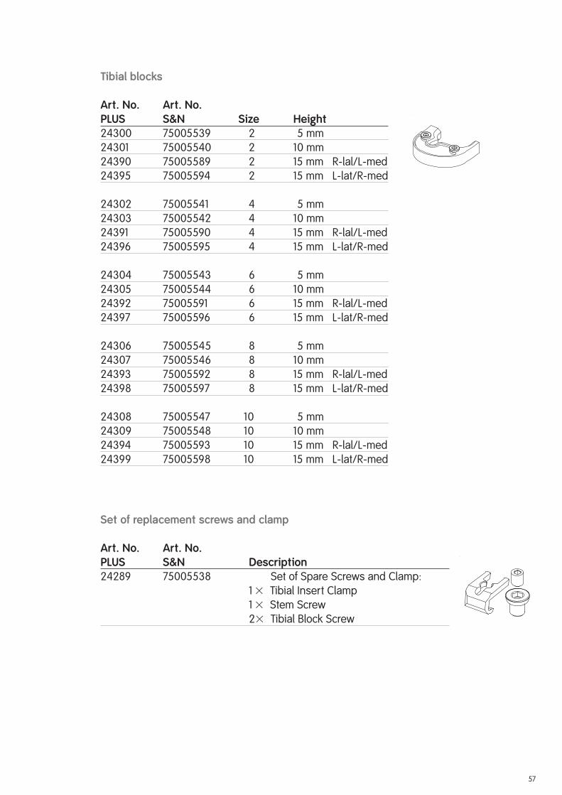
Tibial blocks
Art. No. Art. No.PLUS S&N Size Height24300 75005539 2 5 mm
24301 75005540 2 10 mm
24390 75005589 2 15 mm R-lal/L-med
24395 75005594 2 15 mm L-lat/R-med
24302 75005541 4 5 mm
24303 75005542 4 10 mm
24391 75005590 4 15 mm R-lal/L-med
24396 75005595 4 15 mm L-lat/R-med
24304 75005543 6 5 mm
24305 75005544 6 10 mm
24392 75005591 6 15 mm R-lal/L-med
24397 75005596 6 15 mm L-lat/R-med
24306 75005545 8 5 mm
24307 75005546 8 10 mm
24393 75005592 8 15 mm R-lal/L-med
24398 75005597 8 15 mm L-lat/R-med
24308 75005547 10 5 mm
24309 75005548 10 10 mm
24394 75005593 10 15 mm R-lal/L-med
24399 75005598 10 15 mm L-lat/R-med
Set of replacement screws and clamp
Art. No. Art. No.PLUS S&N Description24289 75005538 Set of Spare Screws and Clamp:
1 � Tibial Insert Clamp
1 � Stem Screw
2 � Tibial Block Screw

58
Cemented stems (conical) [CoCrMo]
Art. No. Art. No.PLUS S&N Height24232 75005515 95 mm
24231 75005514 120 mm
24233 75005516 160 mm
Cementless stems – straight [Ti6Al4V]
Art. No. Art. No.PLUS S&N Size Height24251 75005517 Ø 10 mm 95 mm
24252 75005518 Ø 12 mm 95 mm
24254 75005520 Ø 14 mm 95 mm
24253 75005519 Ø 16 mm 95 mm
24256 75005521 Ø 12 mm 120 mm
24259 75005524 Ø 14 mm 120 mm
24257 75005522 Ø 16 mm 120 mm
24260 75005525 Ø 18 mm 120 mm
24258 75005523 Ø 20 mm 120 mm
24266 75005530 Ø 12 mm 160 mm
24267 75005531 Ø 14 mm 160 mm
24268 75005532 Ø 16 mm 160 mm
24269 75005533 Ø 18 mm 160 mm
24270 75005534 Ø 20 mm 160 mm
24261 75005526 Ø 12 mm 200 mm
24264 75005529 Ø 14 mm 200 mm
24262 75005527 Ø 16 mm 200 mm
24265 75005530 Ø 18 mm 200 mm
24263 75005528 Ø 20 mm 200 mm
Cemented and cementless stems are identical for femoral and tibial components of RT-PLUS™ Modular knee system.

59

60
RT-PLUS™ Modular Instrument Set Set No. PLUS/S&N
0944033/75200235
Instrumentation
Trial stems and reamers Case Set No. PLUS/S&N
0944034/75200236
Art. No. Art. No. PLUS S&N Description Size 240462 75005464 Case Trial Stems, Empty 990019 75007661 Case Lid � 240112 75005341 Trial Stem Ø 10 / 95 mm
240113 75005342 Trial Stem Ø 12 / 95 mm
240114 75005343 Trial Stem Ø 14 / 95 mm
240115 75005344 Trial Stem Ø 16 / 95 mm� 240116 75005345 Trial Stem Ø 12 / 120 mm
240117 75005346 Trial Stem Ø 14 / 120 mm
240118 75005347 Trial Stem Ø 16 / 120 mm
240119 75005348 Trial Stem Ø 18 / 120 mm
240120 75005349 Trial Stem Ø 20 / 120 mm� 240121 75005350 Trial Stem Ø 12 / 160 mm
240122 75005351 Trial Stem Ø 14 / 160 mm
240123 75005352 Trial Stem Ø 16 / 160 mm
240124 75005353 Trial Stem Ø 18 / 160 mm
240125 75005354 Trial Stem Ø 20 / 160 mm� 240126 75005355 Trial Stem Ø 12 / 200 mm
240127 75005356 Trial Stem Ø 14 / 200 mm
240128 75005357 Trial Stem Ø 16 / 200 mm
240129 75005358 Trial Stem Ø 18 / 200 mm
240111 75005340 Trial Stem Ø 20 / 200 mm� 600195 75011898 Extension for Trial Stem Ø 8 mm � 600112 75007098 Reamer + Trial Stem Handle
240461 75005463 Tray Reamer, Empty � 240142 75005360 Stepped Reamer Ø 10 / 16 mm 600232 75007168 IM Rod Ø 8 mm 240380 75005413 Reamer Ø 10 mm
240381 75005414 Reamer Ø 12 mm
240382 75005415 Reamer Ø 14 mm
240383 75005416 Reamer Ø 16 mm
240384 75005417 Reamer Ø 18 mm
240385 75005418 Reamer Ø 20 mm� 240387 75005419 Reamer Alignment Guide EM
61
�
�
�
�
OPTIONAL
�
��
�
�
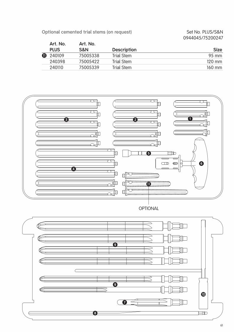
Optional cemented trial stems (on request) Set No. PLUS/S&N
0944045/75200247
Art. No. Art. No. PLUS S&N Description Size� 240109 75005338 Trial Stem 95 mm
240398 75005422 Trial Stem 120 mm
240110 75005339 Trial Stem 160 mm

62
Femoral instruments Case Set No. PLUS/S&N
0944035/75200237
Art. No. Art. No. PLUS S&N Description Size 240463 75005465 Case Femoral Instruments, Empty 990019 75007661 Case Lid � 240169 75005364 IM Femoral Drill Guide, Adjustable � 240002 75005299 Awl � 240003 75005300 Stepped Drill Ø 8 / 14 mm� 251073 75005659 IM Drill with Starter Tip Ø 8 mm� 251065 75005663 Drill Bohrer (2 pieces) Ø 3.2 mm
600179 75007140 Bone Pin (4 pieces) 75 mm
600180 75007141 Bone Pin (4 pieces) 100 mm
600177 75007138 Bone Pin with Head (4 pieces) 25 mm
600178 75007139 Bone Pin with Head (4 pieces) 38 mm
MEM01179 75005420 Allen Wrench SW 3.5� 240391 75018329 Pin Extractor � 240305 75005389 Femoral Sizer 2
240306 75005390 Femoral Sizer 4
240307 75005391 Femoral Sizer 6
240308 75005392 Femoral Sizer 8
240309 75005393 Femoral Sizer 10 600187 75007148 Femoral Suspension Device Revision 600184 75007145 Femoral Bushing 6°� 600183 75007144 Femoral Distal Spacer Revision 7 mm� 600398 75007233 Femoral/Tibial Cutting Block Revision 252746 75005902 Resection Stylus 1 mm� 240401 75005423 Femoral Cutting Block Revision 2
240402 75005424 Femoral Cutting Block Revision 4
240403 75005425 Femoral Cutting Block Revision 6
240404 75005426 Femoral Cutting Block Revision 8
240405 75005427 Femoral Cutting Block Revision 10� 252068 75005857 Quick Lock Handle (2 pieces) � 240149 75005361 Centering Template � 240395 75005421 Box Saw Guide Pos. Device IM 2
240325 75005398 Box Saw Guide Pos. Device IM 4–10� 240326 75005399 Box Saw Guide IM Positioning 2
240327 75005400 Box Saw Guide IM Positioning 4–8
240328 75005401 Box Saw Guide IM Positioning 10� 240335 75005408 Box Saw Guide IM 2
240336 75005409 Box Saw Guide IM 4–10� 240451 75005455 Box Rasp 2
240452 75005456 Box Rasp 4–10
63
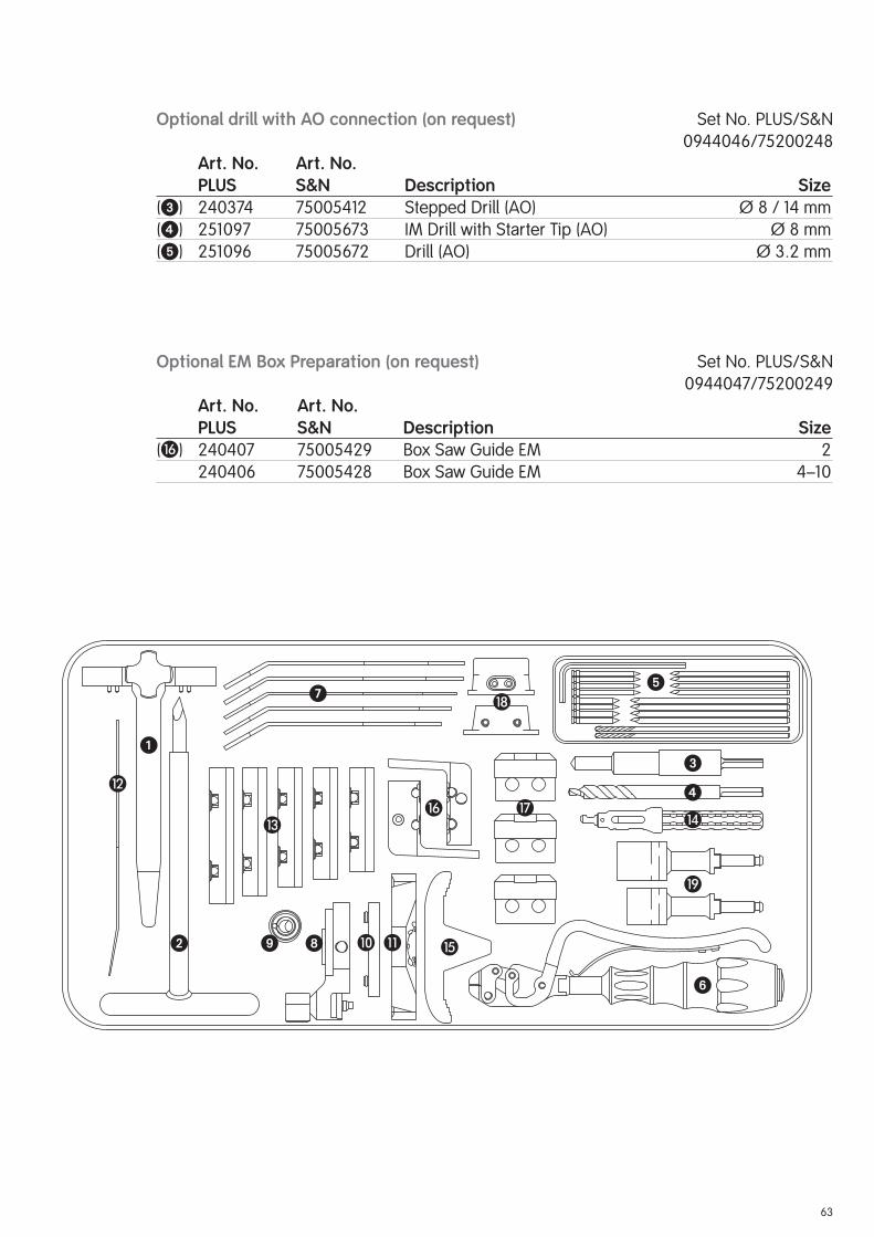
Optional drill with AO connection (on request) Set No. PLUS/S&N
0944046/75200248
Art. No. Art. No. PLUS S&N Description Size (�) 240374 75005412 Stepped Drill (AO) Ø 8 / 14 mm
(�) 251097 75005673 IM Drill with Starter Tip (AO) Ø 8 mm
(�) 251096 75005672 Drill (AO) Ø 3.2 mm
Optional EM Box Preparation (on request) Set No. PLUS/S&N
0944047/75200249
Art. No. Art. No. PLUS S&N Description Size(�) 240407 75005429 Box Saw Guide EM 2
240406 75005428 Box Saw Guide EM 4–10
�
�
�
�
�
�
�
�
� � �
� �
�
�
�

64
Femoral trials Case Set No. PLUS/S&N
0944036/75200238
Art. No. Art. No. PLUS S&N Description Size 240464 75005466 Case Femoral Trials, Empty 990019 75007661 Case Lid � 240300 75005384 Femoral Trial Left 2
240301 75005385 Femoral Trial Left 4
240302 75005386 Femoral Trial Left 6
240303 75005387 Femoral Trial Left 8
240304 75005388 Femoral Trial Left 10� 240330 75005403 Femoral Trial Right 2
240331 75005404 Femoral Trial Right 4
240332 75005405 Femoral Trial Right 6
240333 75005406 Femoral Trial Right 8
240334 75005407 Femoral Trial Right 10� 600204 75007156 Femoral Block Trial (4 pieces) 5 mm
600205 75007157 Femoral Block Trial (4 pieces) 10 mm
600201 75007154 Femoral Block Trial (2 pieces) 15 mm� 600238 75007169 Curved Osteotome

65
�
�
� �
66
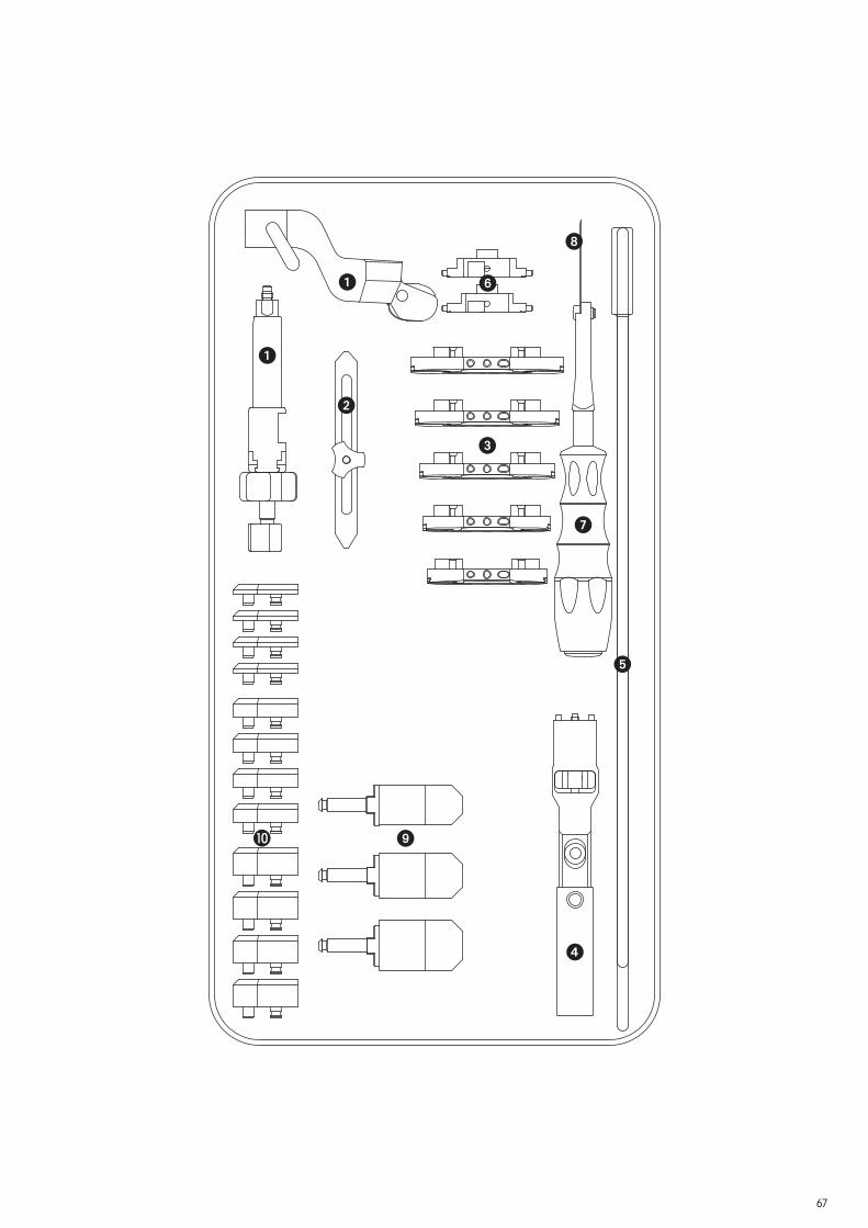
Tibial instruments Case Set No. PLUS/S&N
0944037/75200239
Art. No. Art. No. PLUS S&N Description Size 240465 75005467 Case Tibial Instruments, Empty 990019 75007661 Case Lid � 600162 75007131 Tibial Resection Guide IM (I / II) ± 6 mm� 600173 75010947 Tibia Stylus 1 mm / 11 mm� 240438 75000979 Tibial Sizer 2
240439 75000980 Tibial Sizer 4
240440 75000981 Tibial Sizer 6
240441 75000982 Tibial Sizer 8
240442 75000983 Tibial Sizer 10� 600175 75007137 Tibial Sizer Handle � 600172 75007135 Axial Alignment Rod (I / II) � 240372 75005410 Tibial Chisel Guide 2
240373 75005411 Tibial Chisel Guide 4–10� 22000443 75018080 Chisel Handle MEFL668R 75018330 Chisel Blade 10 mm / 45 mm 240455 75005457 Spacer 8 mm
240456 75005458 Spacer 11 mm
240457 75005459 Spacer 14 mm� 240229 75005381 Spacer Attachment (4 pieces) 5 mm
240230 75005382 Spacer Attachment (4 pieces) 10 mm
240329 75005402 Spacer Attachment (2 pieces) 15 mm
67
�
�
�
�
�
�
�
�
�

68
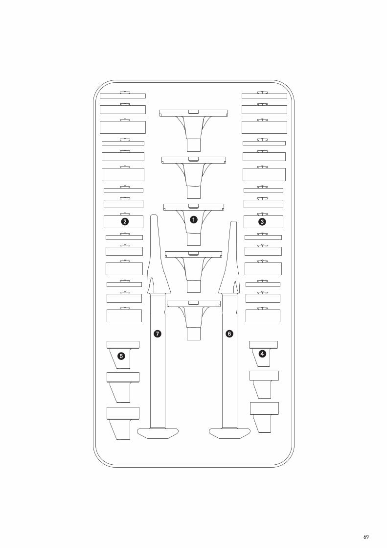
Tibia trials Case Set No. PLUS/S&N
0944038/75200240
Art. No. Art. No. PLUS S&N Description Size 240466 75005468 Case Tibial Trials, Empty 990019 75007661 Case Lid � 240411 75005430 Tibial Trial 2
240412 75005431 Tibial Trial 4
240413 75005432 Tibial Trial 6
240414 75005433 Tibial Trial 8
240415 75005434 Tibial Trial 10� 240416 75005435 Tibial Block Trial R-Lat / L-Med 2 / 5 mm
240418 75005437 Tibial Block Trial R-Lat / L-Med 2 / 10 mm
240470 75005471 Tibial Block Trial R-Lat / L-Med 2 / 15 mm
240420 75005439 Tibial Block Trial R-Lat / L-Med 4 / 5 mm
240422 75005441 Tibial Block Trial R-Lat / L-Med 4 / 10 mm
240471 75005472 Tibial Block Trial R-Lat / L-Med 4 / 15 mm
240424 75005443 Tibial Block Trial R-Lat / L-Med 6 / 5 mm
240426 75005445 Tibial Block Trial R-Lat / L-Med 6 / 10 mm
240472 75005473 Tibial Block Trial R-Lat / L-Med 6 / 15 mm
240428 75005447 Tibial Block Trial R-Lat / L-Med 8 / 5 mm
240430 75005449 Tibial Block Trial R-Lat / L-Med 8 / 10 mm
240473 75005474 Tibial Block Trial R-Lat / L-Med 8 / 15 mm
240432 75005451 Tibial Block Trial R-Lat / L-Med 10 / 5 mm
240434 75005453 Tibial Block Trial R-Lat / L-Med 10 / 10 mm
240474 75005475 Tibial Block Trial R-Lat / L-Med 10 / 15 mm� 240417 75005436 Tibial Block Trial L-Lat / R-Med 2 / 5 mm
240419 75005438 Tibial Block Trial L-Lat / R-Med 2 / 10 mm
240475 75005476 Tibial Block Trial L-Lat / R-Med 2 / 15 mm
240421 75005440 Tibial Block Trial L-Lat / R-Med 4 / 5 mm
240423 75005442 Tibial Block Trial L-Lat / R-Med 4 / 10 mm
240476 75005477 Tibial Block Trial L-Lat / R-Med 4 / 15 mm
240425 75005444 Tibial Block Trial L-Lat / R-Med 6 / 5 mm
240427 75005446 Tibial Block Trial L-Lat / R-Med 6 / 10 mm
240477 75005478 Tibial Block Trial L-Lat / R-Med 6 / 15 mm
240429 75005448 Tibial Block Trial L-Lat / R-Med 8 / 5 mm
240431 75005450 Tibial Block Trial L-Lat / R-Med 8 / 10 mm
240478 75005479 Tibial Block Trial L-Lat / R-Med 8 / 15 mm
240433 75005452 Tibial Block Trial L-Lat / R-Med 10 / 5 mm
240435 75005454 Tibial Block Trial L-Lat / R-Med 10 / 10 mm
240479 75005480 Tibial Block Trial L-Lat / R-Med 10 / 15 mm� 22000398 75005064 Tibial Insert Trial 2 / 8 mm
22000399 75005065 Tibial Insert Trial 2 / 11 mm
22000400 75005066 Tibial Insert Trial 2 / 14 mm� 240075 75005333 Tibial Insert Trial 4–10 / 8 mm
240076 75005334 Tibial Insert Trial 4–10 / 11 mm
240077 75005335 Tibial Insert Trial 4–10 / 14 mm� 22000412 75005074 Tibial Rasp 2 22000413 75005075 Tibial Rasp 4–10
69
��
�
�
�
��

70
Assembly instruments Case Set No. PLUS/S&N
0944039/75200241
Art. No. Art. No. PLUS S&N Description Size 240467 75005469 Case Assembly Instrument, Empty 990019 75007661 Case Lid � 600181 75007142 Slap Hammer � 600300 75007202 Modular Handle (2 pieces) � 600288 75007200 Impactor Small� 600289 75007201 Impactor Large� 600239 75007170 Assembling Block � 600228 75007166 Automatic Hammer � 600299 75007201 Adapter for Automatic Hammer 600230 75007167 Stem Protector Cross 240093 75005337 Screwdriver for Stems (2 pieces) SW 2� 253271 75005998 Screwdriver with Torque � 600279 75007188 Adapter with Spherical Hexagonal Head (2 pieces) SW 3.5 240176 75005371 Plug Inserter
240177 75005372 Impacting Connection � 22000395 75005063 Adapter to Modular Handle SW 6

71
�
�
�
�
�
�
�
�
�
�

72
Patellar instruments Case Set No. PLUS/S&N
0944003/75200207
Art. No. Art. No. PLUS S&N Description Size 22000451 75018088 Case Patellar Instruments, Empty 990019 75007661 Case Lid � 251204 75005702 Patellar Clamp � 252203 75005881 Patellar Clamp Cutting Guide � 251292 75005723 Patellar Trial Ø 26 / 10 mm
251293 75005724 Patellar Trial Ø 29 / 10 mm
251294 75005725 Patellar Trial Ø 32 / 10 mm
251295 75005726 Patellar Trial Ø 35 / 10 mm� 251278 75005717 Patellar Drill with Stop Ø 5.5 mm� 251282 75005719 Patellar Sizer � 251277 75005716 Patellar Inserter � 251230 75005707 Patellar Clamp Bushing Ø 26 mm
251231 75005708 Patellar Clamp Bushing Ø 29 mm
251232 75005709 Patellar Clamp Bushing Ø 32 mm
251233 75005710 Patellar Clamp Bushing Ø 35 mm 251240 75005711 Patellar Drill Guide Ø 26 mm
251241 75005712 Patellar Drill Guideg Ø 29 mm
251242 75005713 Patellar Drill Guide Ø 32 mm
251243 75005714 Patellar Drill Guide Ø 35 mm 251216 75005706 Patellar Mill with Stop Ø 26 mm
251283 75005707 Patellar Mill with Stop Ø 29 mm
251284 75005708 Patellar Mill with Stop Ø 32 mm
251285 75005709 Patellar Mill with Stop Ø 35 mm� 22000327 75005034 Bone Thickness Sizer
Optional patellar trials 8 mm (on request) Set No. PLUS/S&N
0944008/75200212
Art. No. Art. No. PLUS S&N Description Size(�) 251209 75005703 Patellar Trial Ø 26 / 8 mm
251210 75005704 Patellar Trial Ø 29 / 8 mm
251211 75005705 Patellar Trial Ø 32 / 8 mm
Optional reamer/drill with AO coupling type (on request) Set No. PLUS/S&N
0944049/75200251
Art. No. Art. No. PLUS S&N Description Size(�) 22000038 75004871 Patellar Drill with Stop (AO) Ø 5.5 mm
() 22000280 75004989 Patellar Mill with Stop (AO) Ø 26 mm
22000281 75004990 Patellar Mill with Stop (AO) Ø 29 mm
22000282 75004991 Patellar Mill with Stop (AO) Ø 32 mm
22000283 75004992 Patellar Mill with Stop (AO) Ø 35 mm

73
�
�
�
� �
�
�
��
74
Size
4Si
ze 6
Size
8Si
ze10
Size
2
Ø26
Ø29
Ø32
Ø35
Pate
llar
com
pone
nt
Tibi
al c
ompo
nent
Tibi
al in
sert
s
Fem
oral
blo
cks
dist
al/p
oste
rior
Fem
oral
com
pone
ntri
ght/
left
Tibi
al b
lock
s
2118
2* /
8m
m21
192
/ 10
mm
Post
erio
r:24
350
/ 5m
m24
351 /
10m
mD
ista
l:24
371 /
5m
m24
372
/ 10
mm
2437
3 /
15m
m
2431
224
322
2431
424
324
2431
6
2433
224
334
2433
624
338
2434
0
2432
624
318
2432
824
320
2433
0
Dis
tal:
2437
4 /
5m
m24
375
/ 10
mm
2437
6 /
15m
m
Dis
tal:
2437
7 /
5m
m24
378
/ 10
mm
2437
9 /
15m
m
Dis
tal:
2438
0 /
5m
m24
381
/ 10
mm
2438
2 /
15m
m
Dis
tal:
2438
3 /
5m
m24
384
/ 10
mm
2438
5 /
15m
m
Post
erio
r:24
352
/ 5
mm
2435
3 /
10m
m
Post
erio
r:���
2435
4 /
5m
m24
355
/ 10
mm
Post
erio
r:24
356
/ 5
mm
2435
7 /
10m
m
Post
erio
r:24
358
/ 5
mm
2435
9 /
10m
m
2118
3* /
8m
m21
193
/ 10
mm
2404
6 /
8m
m24
047
/ 11
mm
2404
8 /
14m
m
2430
0 /
5m
m24
301
/ 10
mm
2439
0 /
15m
m R
-Lat
/ L
-Med
2439
5 /
15m
m L
-Lat
/ R
-Med
2430
2 /
5m
m24
303
/ 10
mm
2439
1 / 1
5mm
R-L
at /
L-M
ed24
396
/ 15
mm
L-L
at /
R-M
ed
2430
4 /
5m
m24
305
/ 10
mm
2439
2 /
15m
m R
-Lat
/ L
-Med
2439
7 /
15m
m L
-Lat
/ R
-Med
2430
6 /
5m
m24
307
/ 10
mm
2439
3 /
15m
m R
-Lat
/ L
-Med
2439
8 /
15m
m L
-Lat
/ R
-Med
2430
8 /
5m
m24
309
/ 10
mm
2439
4 /
15m
m R
-Lat
/ L
-Med
2439
9 /
15m
m L
-Lat
/ R
-Med
2405
6 /
8m
m24
057
/ 11
mm
2405
8 /
14m
m
2406
6 /
8m
m24
067
/ 11
mm
2406
8 /
14m
m
2407
6 /
8m
m24
077
/ 11
mm
2407
8 /
14m
m
2408
6 /
8m
m24
087
/ 11
mm
2408
8 /
14m
m
2118
4* /
8m
m21
194
/ 10
mm
2119
5 /
10m
m* S
peci
al s
izes
RT-
PLU
S™
Mo
du
lar
Product Overview
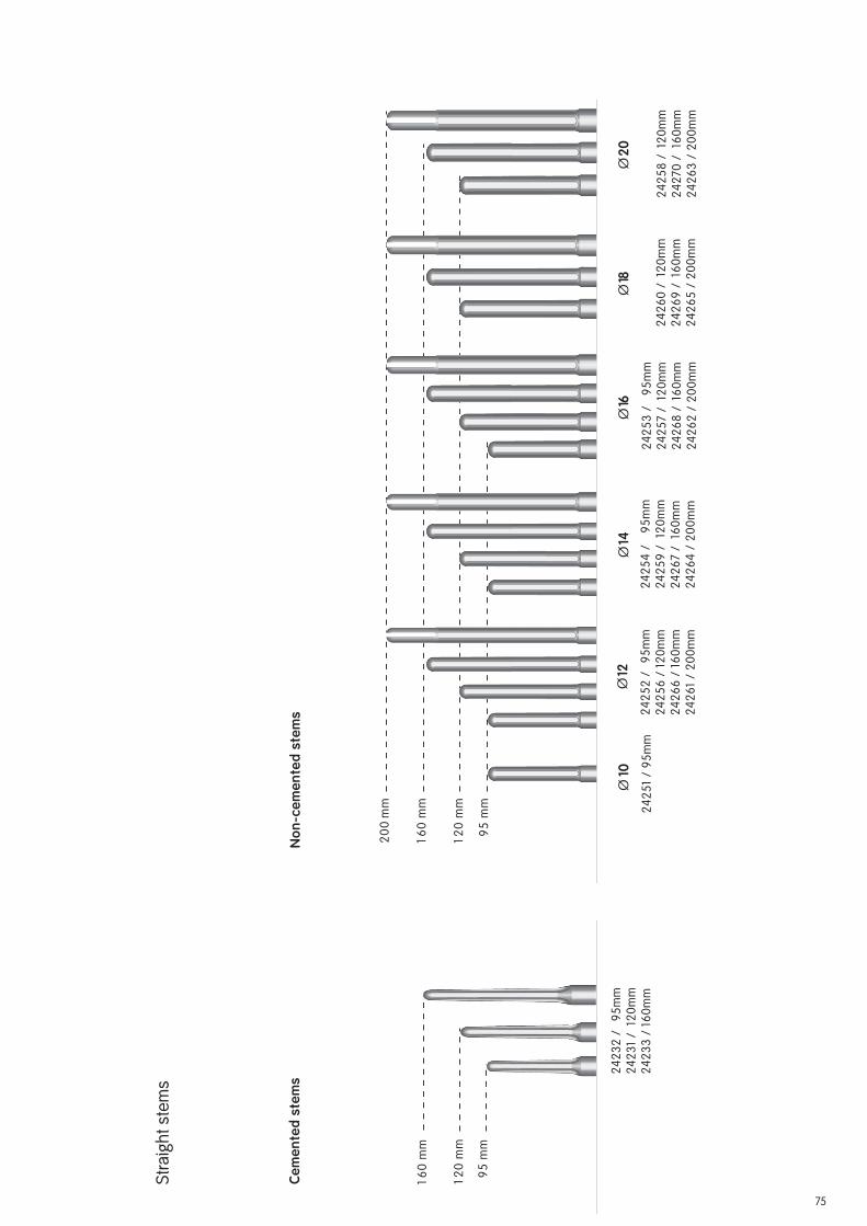
75
Ce
me
nte
d s
tem
sN
on
-ce
me
nte
d s
tem
s
16
0 m
m
12
0 m
m
95
mm
Cem
ente
d st
ems
24
23
2 /
9
5m
m
24
23
1 /
12
0m
m
24
23
3 /
16
0m
m
Cem
ente
d st
ems
Ø10
Ø12
Ø14
Ø16
Ø18
20
0 m
m
16
0 m
m
12
0 m
m
95
mm
Ø20
Non
-cem
ente
d st
ems
24
25
1 /
95
mm
24
25
2 /
9
5m
m
24
25
6 /
12
0m
m
24
26
6 /
16
0m
m
24
26
1 /
20
0m
m
24
25
4 /
9
5m
m
24
25
9 /
12
0m
m
24
26
7 /
16
0m
m
24
26
4 /
20
0m
m
24
25
3 /
9
5m
m
24
25
7 /
12
0m
m
24
26
8 /
16
0m
m
24
26
2 /
20
0m
m
24
26
0 /
12
0m
m
24
26
9 /
16
0m
m
24
26
5 /
20
0m
m
24
25
8 /
12
0m
m
24
270
/
160
mm
24
26
3 /
20
0m
m
Str
aig
ht
ste
ms

76
Note
The following documents are available for your assistance.
Product-accompanying Documents
Documents
Description Lit. No. Product Portfolio PLUS SOLUTION KNEE FAMILY 1685
Sawblades for the PLUS SOLUTION KNEE FAMILY 1403
Surgical Technique “Intramedullary Application” 1313
Product Information 1330
X-Ray Templates (1.15:1) 1135-A-B
X-Ray Templates (1:1) 1584-A-B
Product Overview 1346
Clinical Video “TKR with Severe Joint Instability” 1798


Manufacturer ContactSmith & Nephew Orthopaedics AG For further information please contact
Erlenstrasse 4a our local sales offi ce.
6343 Rotkreuz www.smith-nephew.com
Switzerland
™Trademark of Smith & Nephew Lit. No. 1313-e Ed. 05/09 0 1 2 3
![Design and fabrication of CoCrMo alloy based novel structures8].pdf · Design and fabrication of CoCrMo alloy based novel structures for load bearing implants using laser engineered](https://static.fdocuments.us/doc/165x107/5f0bf3837e708231d4330686/design-and-fabrication-of-cocrmo-alloy-based-novel-8pdf-design-and-fabrication.jpg)