Titanium ElasticNail Surgical Technique - … ELASTIC NAIL TEN.pdf · 4 TEN Titanium ElasticNail...
28
TEN Surgical Technique Titanium ElasticNail Original instruments and implants of the Association for the Study of Internal Fixation – AO/ASIF
Transcript of Titanium ElasticNail Surgical Technique - … ELASTIC NAIL TEN.pdf · 4 TEN Titanium ElasticNail...
TEN
Surgical Technique
Titanium ElasticNail
Original instruments and implants of the Association for the Study of Internal Fixation – AO/ASIF
036.000.207_AA.qxp:036.000.207_AA 02.12.2008 17:22 Uhr Seite U1

036.000.207_AA.qxp:036.000.207_AA 02.12.2008 17:22 Uhr Seite U2

Synthes 1
Table of contents
WarningThis description is not sufficient for immediate application of the instrumentation. Instruction by a surgeon experienced inhandling this instrumentation is highly recommended.
Image intensifier control
TEN Titanium ElasticNail
System description 2
Indications/Contraindications 3
Standard surgical technique 4
Assembly and handling instructions for the 11Cutter for TEN
Additional applications 12
Implant removal 21
Case studies 22
Bibliography 25
036.000.207_AA.qxp:036.000.207_AA 02.12.2008 17:22 Uhr Seite 1

2
The aim of this biological, minimally invasive fracture treatmentis to achieve a level of reduction and stabilisation that is appro-priate to the age of the child.
The biomechanical principle of the elastically-stable intra -medullary nailing (ESIN) is based on the symmetrical bracing ac-tion of two elastic nails inserted into the metaphysis, each ofwhich bears against the inner bone at three points. This pro-duces the following four biomechanical properties: flexural sta-bility, axial stability, translational stability and rotational stability.All four are essential for achieving optimal results (Ref.: Dietz etal. 1997).
TEN Titanium ElasticNail
System description
F
R
R
F
R R
R R
F
F
RR
F
F
Axial stability
F F
S
C2
S
C1
R
Flexural stability
Translational stability Rotational stability
F = force acting on the bone
R = restoring force of the nail
S = shear force
C= compressive force
�
�
�
036.000.207_AA.qxp:036.000.207_AA 02.12.2008 17:22 Uhr Seite 2

Synthes 3
TEN Titanium ElasticNail
Indications/Contraindications
Elastically-stable intramedullary nailing with the TEN TitaniumElasticNail is used primarily for the management of diaphysealand metaphyseal fractures in children. Whether the TEN is indi- cated or not depends upon the age of the patient and the typeand site of the fracture.All three factors must be considered together.
AgeThe age limit depends on the biological development of thechild. Experience has shown that the lower limit is 3–4 yearsand the upper limit 13–15 years.
Type of fracture– transverse fractures– short oblique or transverse fractures with broken-off wedges– long oblique fractures with the possibility of cortical support– spiral fractures– multi-fragment and bifocal fractures– pathological fractures with juvenile bone cysts
Fracture site– femur: diaphyseal– distal femur: metaphyseal– femur: subtrochanteric– lower leg: diaphyseal– lower leg: distal metaphyseal– humerus: diaphyseal and subcapital– humerus: supracondylar– radius and ulna: shaft– radius: neck
Other possible special indications:– humerus and forearm in adults– polytrauma in combination with craniocerebral trauma,
even outside the age range specified above – prophylactic stabilization with juvenile bone cysts– osteogenesis imperfecta
Contraindications– intraarticular fractures– complex femoral fractures, particularly in connection with
overweight (50–60 kg) and/or age (15–16 years)
036.000.207_AA.qxp:036.000.207_AA 02.12.2008 17:22 Uhr Seite 3

4
TEN Titanium ElasticNail
Standard surgical technique
This surgical technique is explained using the example of afemoral shaft fracture and the ascending technique. Variants ofthis standard technique are described in “Additional applica-tions” on page 12.
Careful preoperative planning, the correct choice of implantand a precise rotation check on the basis of the non-operatedextremity are all vital for a good surgical result.
A = 1⁄3 B
B 1⁄3 B
A = 1⁄3 B
1Position child
Place the child in a supine position on a radiolucent operatingtable. The extension table can be used for larger children. Secure small children to the operating table. The assistant ex-tends the injured extremity. Free positioning allows better con-trol of the nail position and rotation. Position the image intensi-fier so that AP and lateral X-rays can be recorded over the fulllength of the femur.
2Reduce fracture
If the extension table is used, reduce the fracturepreoperatively, while closed, under image intensifier control. Ifthe child is freely positioned, the fracture is reduced during theoperation. For complex fractures, cover both legs with sterilesheets so that a rotation comparison can be performed duringoperation.
Fracture reduction can be facilitated by the use of the small F-tool (359.209). Position the F-tool at the level of the fractureso that the two identically aligned arms of the lever bring thefragments into the desired position.
3Determine nail diameter
Measure the isthmus of the medullary cavity on the X-rayimage. The diameter of the individual nail (A) should be 30–40% of the diameter of the medullary cavity (B). Choose nailswith identical diameter to avoid varus or valgus mal -positioning.
036.000.207_AA.qxp:036.000.207_AA 02.12.2008 17:22 Uhr Seite 4

Synthes 5
4Determine nail insertion points
For the ascending technique, the insertion points on the femurare 1–2 cm proximal to the distal epiphyseal plate. In children,this is about one fingerbreadth proximal to the upper pole ofthe patella.
If necessary, check the intended insertion points under the image intensifier.
5Perform incisions
Make the opposing medial and lateral skin incisions at theplanned insertion points and cut distally for 3–4 cm, dependingon the size of the child. On the lateral side especially, the inci-sion of the fascia should be of the same length.
Important: Ensure that the insertion points are outside the jointcapsule and be careful to avoid the epiphyseal plates.
6Open medullary cavity
Precisely matched opening of the medullary cavity on bothsides is essential for optimal symmetrical bracing.
Divide the fascia lata over a sufficient length. Vertically insertthe Awl (359.213) down to the bone and firmly make a centremark. With rotating movements, lower the awl down to an an-gle of 45° in relation to the shaft axis and continue perforatingthe cortical bone at an upward angle. The opening should beslightly larger than the selected nail diameter.
Check the position and insertion depth of the awl with the image intensifier.
Repeat this procedure for access on the opposite side.
Alternative
If the cortical bone is very hard, open up the medullary cavitywith the corresponding Drill Bit (315.280/290/480) and theDouble Drill Guide 4.5/3.2 (312.460). Check the position andinsertion depth of the drill bit with the image intensifier.
Note: Lower the drill by 45° only when the drill is running, otherwise the tip may break.
1–2 cm
45°
036.000.207_AA.qxp:036.000.207_AA 02.12.2008 17:23 Uhr Seite 5

6
7Pre-bend nails
We recommend pre-bending of the implanted part of the nailsto three times the diameter of the medullary canal. The vertexof the arch should be located at the level of the fracture zone.The nail tip should form the continuation of the arch. Pre-bendboth nails in exactly the same way.
Note: The pressure applied internally can be increased by pre-bending the nails to a smaller diameter, thus shifting the nailcrossover points more towards the metaphyses. This can in-crease the stability in complex fractures.
8Load first nail in the inserter
Load the first nail in the inserter (359.219). Align the lasermarking on the end of the nail with one of the guide markingson the inserter (laser markings at the tip, asymmetrical trans-verse bolts at the end). This permits direct visual control of thealignment and rotation of the nail tip in the bone without animage intensifier, thus preventing excessive crossover of thenails (corkscrew effect).
Tighten the nail in the inserter in the desired position using thePin Wrench (321.170) or the Spanner Wrench (321.250).
Alternative
Use the long Inserter (359.201) or the Universal Drill Chuck withT-Handle (393.100). Do not, under any circumstances, strike theuniversal drill chuck with T-handle with a hammer.
2
3dd
036.000.207_AA.qxp:036.000.207_AA 02.12.2008 17:23 Uhr Seite 6

Synthes 7
TEN Titanium ElasticNailStandard surgical technique
9Insert first nail
Insert the nail into the medullary cavity with the nail tip at rightangles to the bone shaft (1). Turn the inserter through 180° (2)and align the nail tip with the axis of the medullary cavity (3). Ifnecessary, check the position of the nail tip with the image in-tensifier.
Note: The laser marking on the end of the nail shows the nailtip alignment. This facilitates nail insertion and helps reduce theX-ray exposure time.
10Advance first nail to the fracture zone
Advance the nail manually up to the fracture site, using rotat-ing movements or gentle taps of the Combined Hammer(359.221) against the striking surface of the inserter. Do notstrike the T-pieces.
Option
If more forceful hammer blows prove necessary, or if thenail needs to be moved back and forth in a targeted manner toachieve fracture reduction, screw the Hammer Guide (359.218)firmly into the inserter, if necessary with the aid of the pinwrench (321.170). Use the combined hammer or Slotted Hammer (357.026).
1
2
3
180°
036.000.207_AA.qxp:036.000.207_AA 02.12.2008 17:23 Uhr Seite 7

8
11Insert second nail
Repeat steps 8 to 10 for the second nail at the opposing insertion point, thereby producing the first crossover of thenails.
12Advance nails
If necessary, perform indirect fracture reduction either by turning the nails, pulling the leg or using the F-tool. Then advance the nails alternately across the fracture zone. Surveythe passage of the nails with the image intensifier in bothplanes also on the other side of the fracture zone.
Note: Any nails that buckle as a result of the reduction manipulations must be replaced and discarded.
036.000.207_AA.qxp:036.000.207_AA 02.12.2008 17:23 Uhr Seite 8

TEN Titanium ElasticNailStandard surgical technique
13Check position of nail tips
Correctly align the nail tips in the proximal fragment in relationto the medullary cavity in the frontal plane. If the tips are correctly located, advance the nails in a proximal direction untilthe fracture is secured. The tips of the nails should only justreach the metaphysis (A). Ensure that the nails cross over for thesecond time only after they have passed the fracture zone.
Note: Do not, under any circumstances, turn the nail throughmore than 180° about its own axis or produce a “corkscrew effect” (more than two nail crossover points).
14Check rotation
When the fracture is provisionally but firmly fixed, check rota-tion before final anchoring and, if necessary, align the nail tipscorrectly. If an extension table is used, aseptically release the legfrom the extension so that the image intensifier can be used tocheck the axial alignment in the proximal femur.
A
Synthes 9
036.000.207_AA.qxp:036.000.207_AA 02.12.2008 17:23 Uhr Seite 9

10
15Trim nails
The nails must be trimmed to the desired length during the op-eration. The ideal cutting point is measured from the bone tothe distal end of the nail.
Starting at the proximal end, estimate the distance (X) betweenthe current position of the nail tips (A) and the definitive an-choring position (B) on the image intensifier projection. This dis-tance plus an extraction length of approx. 1 cm (Y) produces thedistance from the bone to the cutting point.
The nails can be trimmed using the Cutter for TEN (359.217).See page 11 for assembly and handling instructions.
Note: Excessively long nail ends result in pseudobursa for mationand prevent free flexion of the knee. They can also perforatethe skin and cause infections.
16Final positioning and anchoring of nails
Advance the nails to the planned final position by applying gen-tle hammer taps to the bevelled Impactor (359.206). The bevelled part of the impactor must reach the cortical bone.This will ensure a projection of approx. 1 cm (Y) for subsequent removal.
Bend the nail ends upwards slightly with the bevelled impactorto facilitate subsequent implant removal.
Option
If deeper insertion of the nails is desired, apply careful taps withthe straight Impactor (359.205).
A
XY
BX
036.000.207_AA.qxp:036.000.207_AA 02.12.2008 17:23 Uhr Seite 10

Synthes 11
Loosen the stop nut on the cutter and turn the inner cuttingbolt to the neutral position, i.e. engage the cutting bolt so thatthe lettering TOP is at the top. Retighten the stop nut.
Introduce the nail end to be cut through the appropriate open-ing of the cutting sleeve until the black marker ring on the out-side of the sleeve reaches the desired cutting point on the nail.Locate the handle with ratchet over the cutting bolt and trimthe nail.
After trimming, open the stop nut and remove the cut nail end.
If the cutting surface of the cutting bolt has become rough-ened, send the cutter to your Synthes representative for regrinding.
TEN Titanium ElasticNail
Assembly and handling instructions forthe Cutter for TEN (359.217)
Handle359.217.004
Stop Nut359.217.003
Cutting Bolt359.217.001
Cutting Sleeve359.217.002
4.0 mm, 3.5 mm
2.5, 2.0 mm
A
BX
X Y
3.0 mm
036.000.207_AA.qxp:036.000.207_AA 02.12.2008 17:23 Uhr Seite 11

12
Additional applications
TEN Titanium ElasticNail
Femur – Descending technique 13
Radius and ulna 15
Radial neck 16
Humerus – Ascending technique 17
Humerus – Descending technique 18
Lower leg 19
036.000.207_AA.qxp:036.000.207_AA 02.12.2008 17:23 Uhr Seite 12

Synthes 13
1–2 cm
0.5–1 cm
Femur – Descending technique
TEN Titanium ElasticNail
The descending monolateral technique is preferable for frac-tures of the distal third of the femur or the distal metaphysis.The fixation of metaphyseal fractures with the nailing techniquedoes not correspond to the same biomechanical principles asthe fixation of shaft fractures. However, a correct inner supportfor the stabilisation of the nail tips and therefore of the meta-physeal fragment must be guaranteed.
Note the following deviations from the standard technique (pp. 4–10):
Determine nail insertion points
For the descending technique, the monolateral insertion pointsare located antero-laterally in the subtrochanteric area. They areseparated from each other vertically by approx. 1–2 cm and horizontally by 0.5–1 cm.
Note: The bone may split during nail insertion if the insertionpoints are placed too close to each other.
Perform incisions
The incisions should be 4–5 cm long so as to expose the femurthrough a short L-shaped cut in the M. vastus lateralis.
Pre-bend nails
To ensure correct internal bracing, i.e. with 3-point support,bend one of the nails into an S-shape so that the bracing occursat the level of the fracture zone ( ).
036.000.207_AA.qxp:036.000.207_AA 02.12.2008 17:23 Uhr Seite 13

14
Insert first nail
Introduce the simply pre-bent nail, reduce the fracture with thenail and achieve primary stabilisation.
Insert second nail
Insert the S-shaped pre-bent nail (1). After the first contact withthe cortical bone on the opposite side, turn the nail through180° (2).
Final positioning and anchoring of nails
Advance the nails to the epiphyseal plate and align the nail tipsso that they diverge from each other.
180°
1
2180°
036.000.207_AA.qxp:036.000.207_AA 02.12.2008 17:23 Uhr Seite 14

Synthes 15
In the forearm the two bones are nailed in a counter-rotatingmanner using just one nail for each bone, since the radius andulna form a single unit together with the interosseous mem-brane.
Note the following deviations from the standard technique for the femur (pp. 4–10):
Determine nail diameter
The nail diameter should be about two thirds of the medullaryisthmus.
Determine nail insertion points/Perform incisions
Radius: Splint the radius with the ascending technique. The in-sertion point is approx. 2 cm proximal to the distal epiphysealplate. From this point make a 2–3 cm incision on the radial sideproceeding distally. Expose the superficial branch of the radialnerve and retract to one side.
Ulna: Splint the ulna with the descending technique. The inser-tion point is about 2 cm distal to the apophyseal plate. Makethe incision on the dorsoradial side, sparing the olecranonapophysis.
Insert nails
Advance the nails from the distal radius and the proximal ulnaup to the fracture site.
Ideally, the bone that is most difficult to reduce (usually the ra-dius) should be splinted first since this allows better fracture re-duction.
Note: If neither the radius nor the ulna can be reducedafter several attempts, a muscle interposition is the most likelycause. In such cases, the fracture can be reduced openlythrough a small incision over the fracture site of one of thebones.
Final positioning and anchoring of nails
Align the nails so that the tips point toward each other, therebyproviding oval bracing of the interosseous membrane. Thebones take up their normal curved position.
To avoid skin irritation, the nail ends should not project from thebone by more than 5–6 mm.
Radius and ulna
TEN Titanium ElasticNail
180°
036.000.207_AA.qxp:036.000.207_AA 02.12.2008 17:23 Uhr Seite 15

16
Because of its flexibility, the TEN is very suitable for the closedreduction and fixation of neck and head fractures of the radius.Do not pre-bend the nails for these indications.
Note the following deviations from the standard technique for the femur (pp. 4–10):
Determine nail diameter
Select a � 2.0 or 2.5 mm nail for reducing a fractured neck ofradius.
Insert nail
Insert the nail as for a normal radius fracture.
Advance nail to the fracture zone
Advance the nail up to the fracture with gentle hammer tapsand rotating movements. In the event of severe dislocation, ap-ply external pressure to the head of the radius to place it infront of the nail tip.
A severely dislocated head of radius can be moved toward thenail and reduced with the aid of a � 1.2 or 1.6 mm Kirschnerwire (joystick method).
Final positioning and anchoring of nail
Decompact the fracture by applying slight axial pressure to thenail. Reduce the fracture definitively by rotating the nail through180°.
Radial neck
TEN Titanium ElasticNail
Final position
036.000.207_AA.qxp:036.000.207_AA 02.12.2008 17:23 Uhr Seite 16

Synthes 17
The ascending, monolateral nail technique is used for fracturesof the proximal humerus and the humeral shaft, while the de-scending monolateral technique is used for fractures of the dis-tal humerus.
Note the following deviations from the standard technique for the femur (pp. 4–10):
Ascending technique
Perform ascending nailing of the humerus as for the descend-ing nailing of the femur.
Determine nail insertion points
Choose a radial approach for the ascending technique.An ulnar approach risks damaging the ulnar nerve and must beavoided.
The distal insertion point is located 1–2 cm above the epiphy-seal plate. The second insertion point is located about 1–2 cmproximal to the first and is displaced medially by 0.5–1 cm.
Perform incision
Make a 4–5 cm lateral incision above the radial epicondyle. Ex-pose the radial edge of the humerus on the ventral side of theintermuscular septum.
Open medullary cavity
Ideally, a drill should be used to open up the very hard corticalbone.
Final position
Humerus – Ascending technique
TEN Titanium ElasticNail
1–2 cm
1–2 cm
0.5–1 cm
036.000.207_AA.qxp:036.000.207_AA 02.12.2008 17:23 Uhr Seite 17

18
Humerus – Descending technique
TEN Titanium ElasticNail
Descending technique
Perform descending nailing of the humerus as for the ascend-ing technique.
Note the following deviations from the ascending technique for the humerus (p. 17):
Determine nail insertion points
For the descending technique, the insertion points are locatedon the lateral humerus level with the attachment point ofthe deltoid muscle. The nail insertion points are separated fromeach other vertically by 1.5–2.5 cm and horizontally by 0.5–1 cm.
Perform incision
Make a 4–5 cm skin incision and expose the subperiostealhumerus distal to the insertion point.
Final position
036.000.207_AA.qxp:036.000.207_AA 02.12.2008 17:23 Uhr Seite 18

Synthes 19
Lower leg
TEN Titanium ElasticNail
Indications
Lower leg and isolated tibial fractures should preferably betreated conservatively.
Lower leg fractures constitute a special indication for internalfixation by TEN. Nailing is indicated in:
– closed, unstable lower leg fractures from the age of 9– irreducible and non-retainable fractures– polytrauma and severe craniocerebral trauma
Since the tibia is positioned off-centre in relation to the surrounding muscles and since it possesses a triangular cross-section, particular care is indicated when placing the nails.
Always nail the tibia using the descending technique. Do notuse the ascending technique for the tibia.
Note the following deviations from the standard technique for the femur (pp. 4–10):
Determine nail insertion points
The nail insertion points are located on the medial and lateralsides of the tibial tuberosity.
036.000.207_AA.qxp:036.000.207_AA 02.12.2008 17:23 Uhr Seite 19

20
Perform incisions
Make a 2–3 cm skin incision from each planned insertion pointin the cranial direction.
Note: Do not damage the proximal tibial epiphyseal plate andtibial apophysis during perforation of the cortical bone.
Check position of nail tips
Because of the triangular shape of the tibial medullary canal,both nails tend to lie dorsally, which would result in recurvation.
Before hammering the nails home, turn the tips of both nailsslightly posteriorly so as to achieve the physiological antecurva-tion of the tibia.
Note: Compress the fracture to prevent fixation in distraction.
Trim nails
In view of the minimal soft tissue cover, keep the nail ends shortand do not bend upward.
036.000.207_AA.qxp:036.000.207_AA 02.12.2008 17:23 Uhr Seite 20

Synthes 21
Remove implants
The following description for removing the TEN is independentof the indication.
Enter through the old incision site and expose the nail end. Using the Extraction Pliers (359.215) grasp the nail, bend upward slightly and withdraw. If the nail end is tight up againstthe bone, the bevelled Impactor (359.206) can be used tohelp bend the end upward.
Option
If necessary, screw the Hammer Guide (359.218) tightly into theconnecting thread of the extraction pliers using the � 4.5 mmPin Wrench (321.170) and knock the nail out by firm blowsalong the hammer guide with the Combined Hammer(359.221).
Repeat the procedure for the second nail.
Alternative
Remove the nails using the flat-nosed Pliers (359.204) and thecombined hammer or the 500 g Hammer (399.420).
Implant removal
TEN Titanium ElasticNail
036.000.207_AA.qxp:036.000.207_AA 02.12.2008 17:23 Uhr Seite 21

22
Case studies
TEN Titanium ElasticNail
Femur – Standard technique (pp. 4–10)
Preoperative Postoperative Union
Femur – Descending technique (pp. 13/14)
Preoperative Postoperative
036.000.207_AA.qxp:036.000.207_AA 02.12.2008 17:23 Uhr Seite 22
Synthes 23
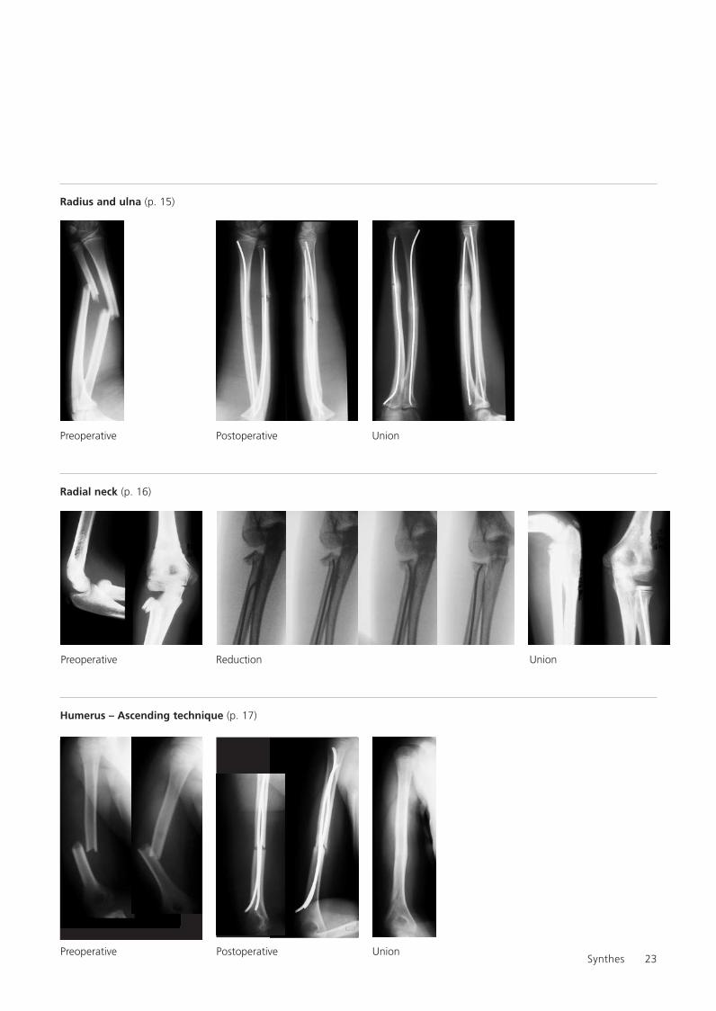
Radius and ulna (p. 15)
Radial neck (p. 16)
Preoperative Postoperative Union
Preoperative Reduction Union
Humerus – Ascending technique (p. 17)
Preoperative Postoperative Union
036.000.207_AA.qxp:036.000.207_AA 02.12.2008 17:23 Uhr Seite 23

24
Humerus – Descending technique (p. 18)
Lower leg (p. 19/20)
TEN Titanium ElasticNailCase studies
Preoperative Postoperative Union
Preoperative Postoperative Union
Scientific consultant and X-ray material by Dr. T. Slongo, Inselspital/Berne, Switzerland
036.000.207_AA.qxp:036.000.207_AA 02.12.2008 17:23 Uhr Seite 24

Synthes 25
Bibliography
TEN Titanium ElasticNail
Dietz HG et al (1997) Intramedulläre Osteosynthese im Wachs-tumsalter. Urban & Schwarzenberg, München
Ligier JN, Métaizeau JP, Prévot J, Lascombes P (1988) Elastic stable intramedullary nailing of femoral shaft fractures inchildren. J Bone Joint Surg; 70-B: 74-7
Métaizeau JP (1988) Ostéosynthèse chez l’enfant par E.C.M.E.S.Sauramps Médical, Montpellier
Rehli V, Slongo T (1991) Die elastisch-stabile endomeduläreSchienung (EES) nach Prévot – Eine ideale Methode zur Versorgung kindlicher Schaftfrakturen. Z Unfallchir Versiche -rungsmed 84: 177-81
Texhammar R, Colton C (1994) AO-Instrumente und -Implantate. Springer, Berlin
036.000.207_AA.qxp:036.000.207_AA 02.12.2008 17:23 Uhr Seite 25

0123 036.
000.
207
SM_7
0782
2 A
A©
Syn
thes
20
05
Prin
ted
in S
witz
erla
ndLA
G
Subj
ect
to m
odifi
catio
ns.
Presented by:
Synthes GmbH Eimattstrasse 3, CH-4436 Oberdorfwww.synthes.com
Ö036.000.207öAAvä
036.000.207_AA.qxp:036.000.207_AA 02.12.2008 17:23 Uhr Seite U4