Tire Pressure Monitoring System User’s...
42
© 2006 Microchip Technology Inc. DS51624B Tire Pressure Monitoring System User’s Guide
Transcript of Tire Pressure Monitoring System User’s...

© 2006 Microchip Technology Inc. DS51624B
Tire PressureMonitoring System
User’s Guide

DS51624B-page ii © 2006 Microchip Technology Inc.
Information contained in this publication regarding deviceapplications and the like is provided only for your convenienceand may be superseded by updates. It is your responsibility toensure that your application meets with your specifications.MICROCHIP MAKES NO REPRESENTATIONS ORWARRANTIES OF ANY KIND WHETHER EXPRESS ORIMPLIED, WRITTEN OR ORAL, STATUTORY OROTHERWISE, RELATED TO THE INFORMATION,INCLUDING BUT NOT LIMITED TO ITS CONDITION,QUALITY, PERFORMANCE, MERCHANTABILITY ORFITNESS FOR PURPOSE. Microchip disclaims all liabilityarising from this information and its use. Use of Microchipdevices in life support and/or safety applications is entirely atthe buyer’s risk, and the buyer agrees to defend, indemnify andhold harmless Microchip from any and all damages, claims,suits, or expenses resulting from such use. No licenses areconveyed, implicitly or otherwise, under any Microchipintellectual property rights.
Trademarks
The Microchip name and logo, the Microchip logo, Accuron, dsPIC, KEELOQ, microID, MPLAB, PIC, PICmicro, PICSTART, PRO MATE, PowerSmart, rfPIC and SmartShunt are registered trademarks of Microchip Technology Incorporated in the U.S.A. and other countries.
AmpLab, FilterLab, Migratable Memory, MXDEV, MXLAB, SEEVAL, SmartSensor and The Embedded Control Solutions Company are registered trademarks of Microchip Technology Incorporated in the U.S.A.
Analog-for-the-Digital Age, Application Maestro, CodeGuard, dsPICDEM, dsPICDEM.net, dsPICworks, ECAN, ECONOMONITOR, FanSense, FlexROM, fuzzyLAB, In-Circuit Serial Programming, ICSP, ICEPIC, Linear Active Thermistor, Mindi, MiWi, MPASM, MPLIB, MPLINK, PICkit, PICDEM, PICDEM.net, PICLAB, PICtail, PowerCal, PowerInfo, PowerMate, PowerTool, REAL ICE, rfLAB, rfPICDEM, Select Mode, Smart Serial, SmartTel, Total Endurance, UNI/O, WiperLock and ZENA are trademarks of Microchip Technology Incorporated in the U.S.A. and other countries.
SQTP is a service mark of Microchip Technology Incorporated in the U.S.A.
All other trademarks mentioned herein are property of their respective companies.
© 2006, Microchip Technology Incorporated, Printed in the U.S.A., All Rights Reserved.
Printed on recycled paper.
Note the following details of the code protection feature on Microchip devices:• Microchip products meet the specification contained in their particular Microchip Data Sheet.
• Microchip believes that its family of products is one of the most secure families of its kind on the market today, when used in the intended manner and under normal conditions.
• There are dishonest and possibly illegal methods used to breach the code protection feature. All of these methods, to our knowledge, require using the Microchip products in a manner outside the operating specifications contained in Microchip’s Data Sheets. Most likely, the person doing so is engaged in theft of intellectual property.
• Microchip is willing to work with the customer who is concerned about the integrity of their code.
• Neither Microchip nor any other semiconductor manufacturer can guarantee the security of their code. Code protection does not mean that we are guaranteeing the product as “unbreakable.”
Code protection is constantly evolving. We at Microchip are committed to continuously improving the code protection features of ourproducts. Attempts to break Microchip’s code protection feature may be a violation of the Digital Millennium Copyright Act. If such actsallow unauthorized access to your software or other copyrighted work, you may have a right to sue for relief under that Act.
Microchip received ISO/TS-16949:2002 certification for its worldwide headquarters, design and wafer fabrication facilities in Chandler and Tempe, Arizona, Gresham, Oregon and Mountain View, California. The Company’s quality system processes and procedures are for its PICmicro® 8-bit MCUs, KEELOQ® code hopping devices, Serial EEPROMs, microperipherals, nonvolatile memory and analog products. In addition, Microchip’s quality system for the design and manufacture of development systems is ISO 9001:2000 certified.

TIRE PRESSURE MONITORINGSYSTEM USER’S GUIDE
© 2006 Microchip Technology Inc. DS51624B-page iii
Table of Contents
Preface ........................................................................................................................... 1Introduction............................................................................................................ 1Document Layout .................................................................................................. 1Conventions Used in this Guide ............................................................................ 2Recommended Reading........................................................................................ 3The Microchip Web Site ........................................................................................ 3Customer Support ................................................................................................. 4Document Revision History ................................................................................... 4
Chapter 1. Quick Start Instructions ............................................................................. 51.1 Introduction ..................................................................................................... 5
Chapter 2. System Overview ........................................................................................ 92.1 System Technical Specifications .................................................................... 92.2 Operation Overview ........................................................................................ 92.3 Network Setup Overview .............................................................................. 10
Chapter 3. Hardware Overview .................................................................................. 113.1 Introduction ................................................................................................... 113.2 Base Station Module Overview .................................................................... 113.3 Low Frequency Initiator Module ................................................................... 133.4 Transponder Sensor Module ........................................................................ 143.5 Analog Sensor Calibration ............................................................................ 193.6 Sensor Calibration ........................................................................................ 19
Appendix A. Schematic and Layouts ........................................................................ 23A.1 Introduction .................................................................................................. 23A.2 Base Station Module Schematic (Page 1) ................................................ 24A.3 Base Station Module Schematic (Page 2) ................................................. 25A.4 Base Station Wiring Harness - Schematic ............................................... 26A.5 Base Station Module - Top Layer and Silk Screen .................................... 27A.6 Base Station Module - Bottom Layer ......................................................... 27A.7 Low Frequency Initiator Module - Schematic ........................................... 28A.8 Low Frequency Initiator Module - Top Layer and Silk Screen ..................... 29A.9 Low Frequency Initiator Module - Bottom Layer ........................................ 29A.10 Transponder Sensor Module - Schematic ................................................ 30A.11 Transponder Sensor Module - Top Layer and Silk Screen ...................... 31A.12 Transponder Sensor Module - Bottom Layer ........................................... 31A.13 Circuit Block Figure .................................................................................. 32

Tire Pressure Monitoring System User’s Guide
DS51624B-page iv © 2006 Microchip Technology Inc.
Appendix B. Bill Of Materials (BOM) ..........................................................................33Worldwide Sales and Service .....................................................................................38

TIRE PRESSURE MONITORINGSYSTEM USER’S GUIDE
© 2006 Microchip Technology Inc. DS51624B-page 1
Preface
INTRODUCTIONThis chapter contains general information that will be useful to know before using the Tire Pressure Monitor System. Items discussed in this chapter include:• Document Layout• Conventions Used in this Guide• Recommended Reading• The Microchip Web Site• Customer Support• Document Revision History
DOCUMENT LAYOUTThis document describes how to use the Tire Pressure Monitor System as a develop-ment tool. The manual layout is as follows:• Chapter 1. “Quick Start Instructions” – includes instructions on how to connect
the system together. • Chapter 2. “System Overview” – shows an overview of the Tire Pressure
Monitor System.• Chapter 3. “Hardware Overview” – shows and overview of the hardware used in
the Tire Pressure Monitor System.• Appendix A. “Schematic and Layouts” – shows the schematic and board lay-
out diagrams for the Tire Pressure Monitor System.• Appendix B. “Bill Of Materials (BOM)” – lists the parts used to build the Tire
Pressure Monitor System boards.
NOTICE TO CUSTOMERS
All documentation becomes dated, and this manual is no exception. Microchip tools and documentation are constantly evolving to meet customer needs, so some actual dialogs and/or tool descriptions may differ from those in this document. Please refer to our web site (www.microchip.com) to obtain the latest documentation available.
Documents are identified with a “DS” number. This number is located on the bottom of each page, in front of the page number. The numbering convention for the DS number is “DSXXXXXA”, where “XXXXX” is the document number and “A” is the revision level of the document.
Tire Pressure Monitoring System User’s Guide
DS51624B-page 2 © 2006 Microchip Technology Inc.
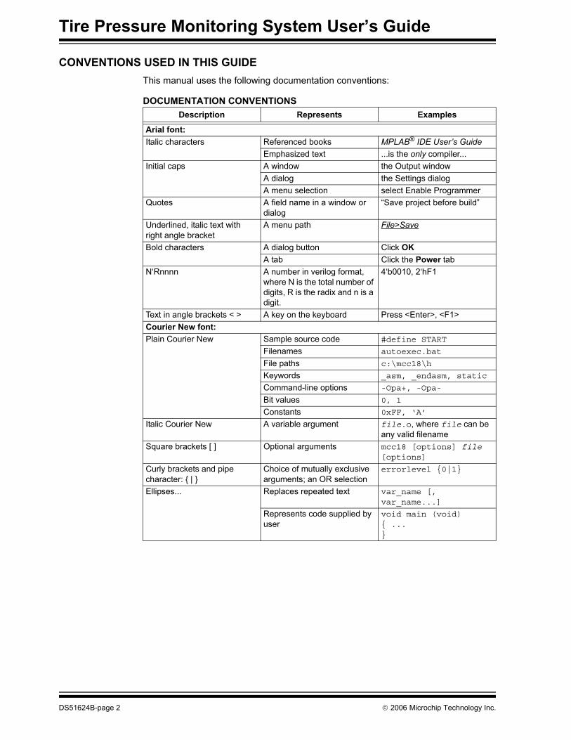
CONVENTIONS USED IN THIS GUIDEThis manual uses the following documentation conventions:
DOCUMENTATION CONVENTIONSDescription Represents Examples
Arial font:Italic characters Referenced books MPLAB® IDE User’s Guide
Emphasized text ...is the only compiler...Initial caps A window the Output window
A dialog the Settings dialogA menu selection select Enable Programmer
Quotes A field name in a window or dialog
“Save project before build”
Underlined, italic text with right angle bracket
A menu path File>Save
Bold characters A dialog button Click OKA tab Click the Power tab
N‘Rnnnn A number in verilog format, where N is the total number of digits, R is the radix and n is a digit.
4‘b0010, 2‘hF1
Text in angle brackets < > A key on the keyboard Press <Enter>, <F1>Courier New font:Plain Courier New Sample source code #define START
Filenames autoexec.bat
File paths c:\mcc18\h
Keywords _asm, _endasm, static
Command-line options -Opa+, -Opa-
Bit values 0, 1
Constants 0xFF, ‘A’
Italic Courier New A variable argument file.o, where file can be any valid filename
Square brackets [ ] Optional arguments mcc18 [options] file [options]
Curly brackets and pipe character: { | }
Choice of mutually exclusive arguments; an OR selection
errorlevel {0|1}
Ellipses... Replaces repeated text var_name [, var_name...]
Represents code supplied by user
void main (void){ ...}

Preface
© 2006 Microchip Technology Inc. DS51624B-page 3
RECOMMENDED READINGThis user's guide describes how to use Tire Pressure Monitor System. The following Microchip documents are available and recommended as supplemental reference resources.MCP201 Data Sheet, “LIN Transceiver with Voltage Regulator” (DS21730)MCP2030 Data Sheet, “Three-Channel Analog Front-End Device“ (DS21981)HCS365 Data Sheet “KEELOQ® Code Hopping Encoder“ (DS41109) MCP3550/1/3 Data Sheet, “Low-Power Single Channel 22-Bit Delta Sigma ADCs“ (DS21950)TC4421/22 Data Sheet, “9A High-Speed Mosfet Drivers” (DS21420)AN232, "Low Frequency Magnetic Transmitter Design" (DS00232)AN617, “Fixed Point Routines“ (DS00617)AN695, “Interfacing Pressure Sensors to Microchip's Analog Peripherals“ (DS00695)AN990, “Analog Sensor Conditioning Circuits - An Overview“ (DS00990)AN1009, “LIN 2.0 Compliant Driver Using the PIC18XXXX” (DS01009)Passive Keyless Entry (PKE) Reference Design User’s Manual (21986)LIN Specification Package, Revision 1.3 (http://www.lin-subbus.org)
THE MICROCHIP WEB SITEMicrochip provides online support via our web site at www.microchip.com. This web site is used as a means to make files and information easily available to customers. Accessible by using your favorite Internet browser, the web site contains the following information:• Product Support – Data sheets and errata, application notes and sample
programs, design resources, user’s guides and hardware support documents, latest software releases and archived software
• General Technical Support – Frequently Asked Questions (FAQs), technical support requests, online discussion groups, Microchip consultant program member listing
• Business of Microchip – Product selector and ordering guides, latest Microchip press releases, listing of seminars and events, listings of Microchip sales offices, distributors and factory representatives

Tire Pressure Monitoring System User’s Guide
DS51624B-page 4 © 2006 Microchip Technology Inc.
CUSTOMER SUPPORTUsers of Microchip products can receive assistance through several channels:• Distributor or Representative• Local Sales Office• Field Application Engineer (FAE)• Technical Support• Development Systems Information LineCustomers should contact their distributor, representative or field application engineer for support. Local sales offices are also available to help customers. A listing of sales offices and locations is included in the back of this document.Technical support is available through the web site at: http://support.microchip.com
DOCUMENT REVISION HISTORY
Revision A (August 2006)• Initial Release of this Document.

TIRE PRESSURE MONITORINGSYSTEM USER’S GUIDE
© 2006 Microchip Technology Inc. DS51624B-page 5
Chapter 1. Quick Start Instructions
1.1 INTRODUCTIONThis section provides the user a quick step-by-step instruction guide on how to get the Tire Pressure Monitor System operational.1. Connect the Base Station module (J2) with the Low Frequency (LF) Initiator mod-
ule (J4) with the connector cable provided with the kit to establish the Local Inter-connect Network (LIN) physical connections.
Note: This reference design provides only the typical calibration values used during development. Therefore, the accuracy of the measurements is not guaranteed. The user is responsible for performing the calibration routine for their applications. Please contact sensor manufacturing for additional information regarding this topic.

Tire Pressure Monitoring System User’s Guide
DS51624B-page 6 © 2006 Microchip Technology Inc.
2. Apply power to the Sensor module by inserting a 3V NiHM (CR2320) battery. The LED will light to indicate that the power is supplied.

Quick Start Instructions
© 2006 Microchip Technology Inc. DS51624B-page 7
3. Supply power to either the Base Station module or the LF Initiator module with a 9V - 18V supply. Only one power source is needed if the power is shared on the LIN network. The LEDs will light to indicate that the power is connected.
4. The LCD module should be powered at this time. The pressure and temperature data is displayed on the LCD for each Sensor module connected to the LIN net-work. Check power and connection if no information is shown.

Tire Pressure Monitoring System User’s Guide
DS51624B-page 8 © 2006 Microchip Technology Inc.
NOTES:

TIRE PRESSURE MONITORINGSYSTEM USER’S GUIDE
© 2006 Microchip Technology Inc. DS51624B-page 9
Chapter 2. System Overview
2.1 SYSTEM TECHNICAL SPECIFICATIONS
2.2 OPERATION OVERVIEWThe Base Station wakes up the Sensor modules in each tire through the Low Frequency Initiator to poll the pressure, temperature data and checks the battery level in a sequential manner. The Base Station communicates to the LF initiator via the LIN network. The LF initiator transmits a wake up challenge via a 125 kHz ASK modulated signal to the Tire sensor module after a command has been received from the Base Station. The 3-axis Analog Front End (MCP2030) of the Tire Sensor module validates the incoming challenge and wakes up the microcontroller from sleep only if the pream-bles match. The Tire Sensor module will then measure the pressure and the tempera-ture, check the battery level and transmits the data to the Base Station via a 433.9 MHz signal. The Base Station will display the information on the LCD after receiving the data.The Base Station module contains a PIC18F4680. It is also implemented with a MCP201 LIN Transceiver and MCP2551 CAN Transceiver for communications via LIN or CAN.The LF Initiator module contains a PIC18F2680. The module also contains a MCP201 and MCP2551 for LIN or CAN communication. The Tire Sensor module contains a PIC16F684 with a MCP2030, a three-axis Analog Front-End (AFE). The analog pressure sensor used is the MS5407-AM from Intersema.
UHF Communication Frequency: 433.92 MHzLF Communication Frequency: 125 kHzNetwork Connectivity: LIN or CAN, LIN is used in the designModulation Format: ASKEncoding Method: PWM
Tire Pressure Monitoring System User’s Guide
DS51624B-page 10 © 2006 Microchip Technology Inc.
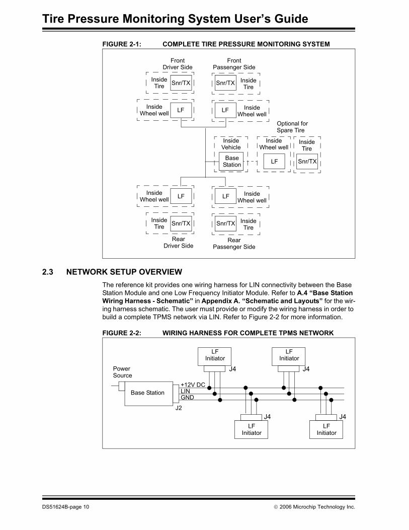
FIGURE 2-1: COMPLETE TIRE PRESSURE MONITORING SYSTEM
2.3 NETWORK SETUP OVERVIEWThe reference kit provides one wiring harness for LIN connectivity between the Base Station Module and one Low Frequency Initiator Module. Refer to A.4 “Base Station Wiring Harness - Schematic” in Appendix A. “Schematic and Layouts” for the wir-ing harness schematic. The user must provide or modify the wiring harness in order to build a complete TPMS network via LIN. Refer to Figure 2-2 for more information.
FIGURE 2-2: WIRING HARNESS FOR COMPLETE TPMS NETWORK
InsideTire
InsideTire
InsideWheel well
InsideWheel well
InsideWheel well
InsideTire
InsideWheel well
Snr/TX
LF
FrontDriver Side
Snr/TX
LF
FrontPassenger Side
LF
Snr/TX
RearDriver Side
LF
Snr/TX
RearPassenger Side
BaseStation
Optional forSpare Tire
InsideTire
InsideWheel well
LF
InsideTire
Snr/TX
InsideVehicle
Base Station
PowerSource
LFInitiator
LFInitiator
LFInitiator
LFInitiator
J4 J4
J4 J4J2
+12V DCLINGND

TIRE PRESSURE MONITORINGSYSTEM USER’S GUIDE
© 2006 Microchip Technology Inc. DS51624B-page 11
Chapter 3. Hardware Overview
3.1 INTRODUCTIONThe following section provides and overview of the hardware used in the Tire Pressure Monitoring System.
3.2 BASE STATION MODULE OVERVIEW
3.2.1 Technical Specifications
3.2.2 MicrocontrollerThe microcontroller implemented is a PIC18F4680 for this module based on the number of features offered by this device. The PIC18F4680 has both a CAN controller and a LIN compatible EUSART to interface to in-vehicle networks.
3.2.3 UHF ReceiverThe RF input is an AM super-regenerative compact hybrid module, that is used to capture decoded data from an AM Transmitter. The receiver has very high frequency stability over a wide operating temperature and tolerant of mechanical vibrations or manual handling. A laser trimmed on board inductor, removes the need for any adjustable components.
3.2.4 LCDA standard 16 pin 2x16 monochromes LCD is used to display the tire pressure and temperature data
3.2.5 ConnectivityA MCP201 LIN transceiver and a MCP2551 CAN transceiver are provided on board to provide a way of connecting to LIN or CAN networks. This reference design uses the LIN to communicate between the Base Station and the LF Initiator(s) that is/are connected to the LIN network. The capacitor between the LIN bus pin and ground should have its value adjusted for the particular network topology. A large pull-up resistor on the nFault/SLPS pin ensures that the device resets to a standard slope control profile. Refer to the MCP201 Data Sheet, “LIN Transceiver with Voltage Regulator” (DS21730) for more information. Refer to Appendix A. “Schematic and Layouts”.
UHF Receiving Frequency: 433.92 MHzNormal Operating Voltage: 9 - 18VNormal Operating Current: ~ 64 mACommunication Protocols: CAN and LINLiquid Crystal Display (LCD): 2x16
Tire Pressure Monitoring System User’s Guide
DS51624B-page 12 © 2006 Microchip Technology Inc.
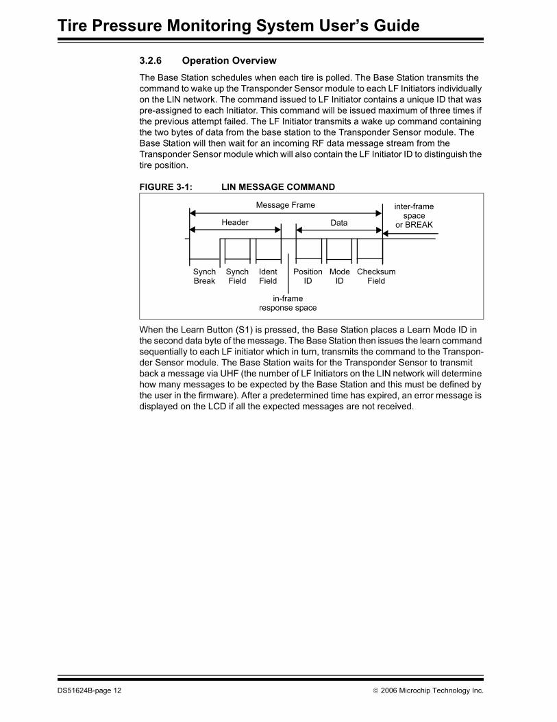
3.2.6 Operation OverviewThe Base Station schedules when each tire is polled. The Base Station transmits the command to wake up the Transponder Sensor module to each LF Initiators individually on the LIN network. The command issued to LF Initiator contains a unique ID that was pre-assigned to each Initiator. This command will be issued maximum of three times if the previous attempt failed. The LF Initiator transmits a wake up command containing the two bytes of data from the base station to the Transponder Sensor module. The Base Station will then wait for an incoming RF data message stream from the Transponder Sensor module which will also contain the LF Initiator ID to distinguish the tire position.
FIGURE 3-1: LIN MESSAGE COMMAND
When the Learn Button (S1) is pressed, the Base Station places a Learn Mode ID in the second data byte of the message. The Base Station then issues the learn command sequentially to each LF initiator which in turn, transmits the command to the Transpon-der Sensor module. The Base Station waits for the Transponder Sensor to transmit back a message via UHF (the number of LF Initiators on the LIN network will determine how many messages to be expected by the Base Station and this must be defined by the user in the firmware). After a predetermined time has expired, an error message is displayed on the LCD if all the expected messages are not received.
Message Frame
Header Data
Position Mode ChecksumIdentSynchSynch
in-frameresponse space
Break Field Field ID ID Field
inter-framespace
or BREAK

Hardware Overview
© 2006 Microchip Technology Inc. DS51624B-page 13
3.3 LOW FREQUENCY INITIATOR MODULE
3.3.1 Technical Specifications
3.3.2 System OverviewThe LF Transmitter is derived from the design described in Application Note AN232, "Low Frequency Magnetic Transmitter Design" (DS00232).The hardware design of the LF Initiator module is identical to the LF module used in Microchip PKE reference design (APGRD001). Refer to Chapter 2 of the “PKE Reference Design User Guide” for more information on this module. Refer to Appendix A. “Schematic and Layouts”.
3.3.3 Operation OverviewLF Initiator is connected to Base Station Module through the LIN network. Each LF Initiator is assigned a unique ID which is also used by the system to distinguish the tire location during normal operation. Once a command from the Base Station has been received, the LF Initiator transmits a wake-up challenge to the Transponder Sensor module via a 125 kHz modulated signal. The format of the signal is user configurable and also depends on the configurations of the AFE output filter on the Transponder Sensor module.Refer to 3.4.3.3 “LF Message Overview” for detail description of the LF message formatting.
3.3.4 Reference MaterialRefer to Recommended Reading in the Preface section.
LF Transmitting Frequency: 125 kHzConnectivity: LIN or CAN, LIN is used for this design
Tire Pressure Monitoring System User’s Guide
DS51624B-page 14 © 2006 Microchip Technology Inc.
3.4 TRANSPONDER SENSOR MODULE
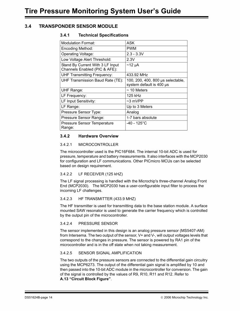
3.4.1 Technical Specifications
3.4.2 Hardware Overview
3.4.2.1 MICROCONTROLLER
The microcontroller used is the PIC16F684. The internal 10-bit ADC is used for pressure, temperature and battery measurements. It also interfaces with the MCP2030 for configuration and LF communications. Other PICmicro MCUs can be selected based on design requirement.
3.4.2.2 LF RECEIVER (125 kHZ)
The LF signal processing is handled with the Microchip's three-channel Analog Front End (MCP2030). The MCP2030 has a user-configurable input filter to process the incoming LF challenges.
3.4.2.3 HF TRANSMITTER (433.9 MHZ)
The HF transmitter is used for transmitting data to the base station module. A surface mounted SAW resonator is used to generate the carrier frequency which is controlled by the output pin of the microcontroller.
3.4.2.4 PRESSURE SENSOR
The sensor implemented in this design is an analog pressure sensor (MS5407-AM) from Intersema. The two output of the sensor, V+ and V-, will output voltages levels that correspond to the changes in pressure. The sensor is powered by RA1 pin of the microcontroller and is in the off state when not taking measurement.
3.4.2.5 SENSOR SIGNAL AMPLIFICATION
The two outputs of the pressure sensors are connected to the differential gain circuitry using the MCP6273. The output of the differential gain signal is amplified by 10 and then passed into the 10-bit ADC module in the microcontroller for conversion. The gain of the signal is controlled by the values of R9, R10, R11 and R12. Refer to A.13 “Circuit Block Figure”.
Modulation Format: ASKEncoding Method: PWMOperating Voltage: 2.3 - 3.3VLow Voltage Alert Threshold: 2.3VStand By Current With 3 LF Input Channels Enabled (PIC & AFE):
~12 μA
UHF Transmitting Frequency: 433.92 MHzUHF Transmission Baud Rate (TE): 100, 200, 400, 800 μs selectable,
system default is 400 μsUHF Range: ~ 10 MetersLF Frequency: 125 kHzLF Input Sensitivity: ~3 mVPPLF Range: Up to 3 MetersPressure Sensor Type: AnalogPressure Sensor Range: 1-7 bars absolutePressure Sensor Temperature Range:
-40 - 125°C

Hardware Overview
© 2006 Microchip Technology Inc. DS51624B-page 15
3.4.2.6 POWER
The module is powered by a standard Lithium 3V coin cell battery.To reduce power consumption, the LED used for indication should be removed to reduce the standby current consumption. The typical standby current without the LED is about 25 μA (the sum of the power down current of the microcontroller and the active current of three-channel analog front end).In addition, the LF Receiver has all three channels enabled and powered on all the time for incoming signal detection. One or two channels can be disabled or a periodic detection method can be implemented to further reduce the overall standby current usage. Refer to Appendix A. “Schematic and Layouts”.
3.4.3 Operation OverviewWhen the Transponder Sensor module receives a LF (125 kHz) wake up challenge message, the Analog Front End validates the incoming challenge. Only after a valid message has been received, the microcontroller is awakened from sleep mode. The action taken by the module is determined by the received commands. Normal request measures the tire pressure and temperature. Learn Mode request assigns a new ID to the sensor module for future operations prior to the measurements. The Transponder Sensor module then transmits the data to the base station via UHF (433.9 MHz) and returns to Sleep mode if no other interrupts were detected.To reduce power consumption, the pressure sensor and the op-amp for signal amplifications are normally powered off. These two devices are powered on only during measurements.

Tire Pressure Monitoring System User’s Guide
DS51624B-page 16 © 2006 Microchip Technology Inc.
FIGURE 3-2: SENSOR MODULE FLOW CHART
Module Initialization
Any Incoming LF Challenge Command?
No
Enter Sleep Mode
Measure BatteryLevel
Yes
Battery Level Okay? Yes
No
Clear Vlow Flag
Measure Pressure
Measure Temperature
Perform Compensation
Routine
Set Vlow Flag
Transmit Data to BaseStation
Valid Challenge Command?
Yes
Wake Up PIC From Sleep Mode
NoLF INT
Read Incoming Messages
Learn Mode Command
Recv?
No
Yes
Save New ID

Hardware Overview
© 2006 Microchip Technology Inc. DS51624B-page 17
3.4.3.1 LEARN MODE OVERVIEW
When a Learn Mode ID is received, the module will save the new Tire Location ID and use it as its default ID for all future normal transmissions until another Learn Mode ID is received. This feature can be used to "re-learn" the tires after tire rotations or if a new Transponder Sensor module has been installed.
3.4.3.2 ANALOG FRONT END OVERVIEW
The user configurable output filter of the MCP2030 is utilized to prevent the microcontroller from being awakened unnecessarily by either noise or LF signals from other unknown sources. The data is outputted to the microcontroller only when the pre-amble of the incoming message matches the pre-configured filter settings. The MCP2030 can be configured via SPI by writing to the seven configuration registers through the microcontroller. The number of channels enabled can also be controlled through these configuration registers. Refer to the MCP2030 data sheet (DS21981) for more information.
3.4.3.3 LF MESSAGE OVERVIEW
The incoming LF message from the LF Initiator Module consists of the following in a 125 kHz modulated format:• A required minimum of 4 ms ON time for AGC stabilization• A 500 μs OFF delay• A 2 ms ON time for the output filter (user configurable in AFE)• A 2 ms OFF for the output filter time (user configurable in AFE)• Two bytes of data (maximum of 8 bytes)
- Tire Location ID (user defined)- System Mode ID (user defined)
FIGURE 3-3: LF MESSAGE FORMAT
Note: Due to the possibility that one LF Initiator can wake up multiple Transpon-der Sensor modules in a full system setup (4 LF Initiators with 4 Sensor Modules) during development due to the close proximity, either the transmitting power of the LF Initiators should be reduced or the distance between the module sets (1 set = 1 LF Initiator + 1 Transponder Sensor) should be kept at a maximum where they will not cause interference with each other. Refer to Application Note AN232 for more details on the LF Transmitter.
Transmission Direction LSb First
Mode ID (1 byte) 4 ms
125 kHz Base Frequency
Data Wake-Up 125 kHz Preamble
500 μs
2 ms 2 ms Tire Location ID
LOGIC ‘0’
LOGIC ‘1’
BitPeriod
(1 byte

Tire Pressure Monitoring System User’s Guide
DS51624B-page 18 © 2006 Microchip Technology Inc.
3.4.3.4 RF MESSAGE OVERVIEW
The transmitted message follows the HCS365 PWM format via a 433 MHz carrier signal, which consists of:• A preamble (31 TE, 50% duty cycle) for baud rate calculation on the receive side• A header (4 or 10 Te, user selectable) • Data bytes:
- Tire Location ID (1 Byte, user defined)- Sensor ID (2 Bytes, user defined)- Pressure Data (2 Bytes)- Temperature Data (2 Bytes)- Battery Low Flag (1 Bit)- Dummy Bits (7 Bits)
Refer to the HCS365 data sheet (DS41109) for more information.
FIGURE 3-4: RF MESSAGE FORMAT
3.4.3.5 PRESSURE MEASUREMENT
• Drive pin RC0 and RA1 high to power up the sensor and the Op-Amp (MCP6273) that is used for signal amplification
• Enable the Op-Amp with pin RA5• Pin RC2 is set up as the analog input to the internal ADC for pressure measure-
ment
3.4.3.6 TEMPERATURE MEASUREMENT
• Drive pin RC0 pin high to power up the sensor and the op-amp used for signal amplification. This also pulls the sensor bridge high through R5. The R5 and the sensor bridge form a resistive divider which is monitored by the internal ADC through pin RA1. Since the sensor internal bridge resistance is temperature dependent, the voltage on the resistor divider will change accordingly.
• Pin RC0 is configured as the analog input of the internal ADC. Vref for the ADC is selected as internal which is equal to the battery voltage minus the diode drop.
• The recommended serial resistor (R5) value should be 10 kOhm or greater to minimize the influence of the parasitic of the microcontroller pins (about 200 Ohm).
LOGIC "1"
Data Bytes
LOGIC "0"
4-10
Header
TE TE TE
xTE
1 16
TBP
31xTe 50% Preamble
Transmission Direction LSb First
Note: For the next three sections, refer to A.13 Circuit Block Figure in Appendix A. “Schematic and Layouts” for circuit block diagram.

Hardware Overview
© 2006 Microchip Technology Inc. DS51624B-page 19
3.4.3.7 BATTERY MEASUREMENT
• The battery measurement is implemented by comparing the difference between the constant forward voltage drop of a diode (D3) with the battery voltage level using the internal ADC in the microcontroller. Pin RC1 is set up as the input to ADC for battery measurement. A threshold value of 2.3V is selected to ensure the proper operation of the internal ADC. The Battery Low flag will be set if the battery falls below the threshold value.
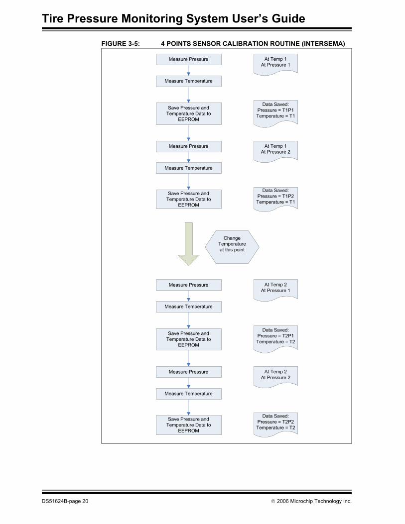
3.5 ANALOG SENSOR CALIBRATIONThe calibration method recommended by Intersema for the optimal sensor performance is the 4-point calibration routine using the simple linear sensor model described in the Intersema application note (AN402). Total of four independent mea-surements performed at two different temperatures and pressures are used to calcu-late and compensate for the variations in the performance of the sensor due to process variations. Refer to Application Note AN402 from Intersema for more details regarding analog sensor calibration methods.
3.6 SENSOR CALIBRATIONThe multiplication and division subroutines used in the sensor calibration/compensa-tion routine are derived from the math subroutines described in Microchip’s Application Note AN617, “Fixed Point Routines”. Refer to this application note for more descrip-tions on the 16x16 bits multiplication and 32/16 bits division routines. The flow charts for the addition routine (Figure 3-6) and subtraction routine (Figure 3-7) are included for references.
Note: This method of the temperature measurement is not the most accurate way to monitor the temperature. An external temperature sensor should be used, if high accuracy is desired.
Note: The internal ADC minimum required Vref voltage is 2.2V. In order to achieve the 1LSB accuracy, Vref voltage value of 2.7V or higher is required.
Note: This reference design provides only the typical calibration values used during development and the calibration values will vary from unit to unit. Therefore, the accuracy of the measurements is not guaranteed. The user is responsible for performing the calibration routine for their applications. Please contact sensor manufacturing for additional information regarding this topic.
Tire Pressure Monitoring System User’s Guide
DS51624B-page 20 © 2006 Microchip Technology Inc.
FIGURE 3-5: 4 POINTS SENSOR CALIBRATION ROUTINE (INTERSEMA)
Measure Pressure At Temp 1At Pressure 1
Measure Temperature
Save Pressure and Temperature Data to
EEPROM
Data Saved: Pressure = T1P1Temperature = T1
Measure Pressure At Temp 1At Pressure 2
Measure Temperature
Save Pressure and Temperature Data to
EEPROM
Data Saved: Pressure = T1P2Temperature = T1
Measure Pressure At Temp 2At Pressure 1
Measure Temperature
Save Pressure and Temperature Data to
EEPROM
Data Saved: Pressure = T2P1Temperature = T2
Measure Pressure At Temp 2At Pressure 2
Measure Temperature
Save Pressure and Temperature Data to
EEPROM
Data Saved: Pressure = T2P2Temperature = T2
Change Temperature at this point

Hardware Overview
© 2006 Microchip Technology Inc. DS51624B-page 21
FIGURE 3-6: SENSOR_TX ADD FLOWCHART
Sflag Set?
data1H > data2H?
Set Aflag
data1L + data2H
Is there a Carry?
data1H =data1H +1
data1H =data1H + data2H
Call Subtraction Routine
Aflag Set?
Clear SflagClear Aflag
Return
Yes
No
Yes
No
Yes
No
Yes
No

Tire Pressure Monitoring System User’s Guide
DS51624B-page 22 © 2006 Microchip Technology Inc.
FIGURE 3-7: SENSOR_TX SUB FLOWCHART
3.6.1 Reference DocumentsPROVIDE LATER
Byte1H – Byte2H
Result = 0?
A borrow ocurred?
Set Nflag
Byte1H = 2's compliment of Byte1H + 1
Byte1L – Byte2L
Nflag AND borrow both = 0?
Nflag = 1?
Set Sflag
Borrow = 1?
Zflag =1?
Byte1H = Byte1H - 1
Byte1L = 2's compliment of Byte1L + 1
Return
Yes
No
Yes
No
Yes
No
YesNo
No
Yes
Set Zflag
Yes
No

TIRE PRESSURE MONITORINGSYSTEM USER’S GUIDE
© 2006 Microchip Technology Inc. DS51624B-page 23
Appendix A. Schematic and Layouts
A.1 INTRODUCTIONThis appendix contains the schematic and PCB layout for the Tire Pressure Monitoring System. Diagrams included:• Base Station Module Schematic (Page 1)• Base Station Module Schematic (Page 2)• Base Station Wiring Harness Schematic• Base Station Module - Top Layer (with silk screen)• Base Station Module - Bottom Layer• Low Frequency Initiator Module Schematic• Low Frequency Initiator Module - Top Layer (with silk screen)• Low Frequency Initiator Module - Bottom Layer• Transponder Sensor Module Schematic• Transponder Sensor Module - Top Layer (with silk screen)• Transponder Sensor Module - Bottom Layer

Tire Pressure Monitoring System User’s Guide
DS51624B-page 24 © 2006 Microchip Technology Inc.
A.2 BASE STATION MODULE SCHEMATIC (PAGE 1)
�

Schematic and Layouts
© 2006 Microchip Technology Inc. DS51624B-page 25
A.3 BASE STATION MODULE SCHEMATIC (PAGE 2)
�

Tire Pressure Monitoring System User’s Guide
DS51624B-page 26 © 2006 Microchip Technology Inc.
A.4 BASE STATION WIRING HARNESS - SCHEMATIC5 5
4 4
3 3
2 2
1 1
DD
CC
BB
AA
LIN
+12V
DC
GN
D
Siz
e
Rev
Sheet
of
AP
GD
raw
n b
y
Chandle
r, A
rizona 8
5224
1.0
Mic
rochip
Technolo
gy,
Inc.
Th
urs
da
y, Ju
ly 0
6,
2006
11
A
AM
AD
Auto
motive P
roducts
Gro
up
2355 W
est
Chandle
r B
lvd.
TP
MS
RefD
es L
IN W
irin
g H
arn
ess
SC
HE
MA
TIC
1
Chuck S
imm
ers
Gauge
Siz
e
Rev
Sheet
of
AP
GD
raw
n b
y
Chandle
r, A
rizona 8
5224
1.0
Mic
rochip
Technolo
gy,
Inc.
Th
urs
da
y, Ju
ly 0
6,
2006
11
A
AM
AD
Auto
motive P
roducts
Gro
up
2355 W
est
Chandle
r B
lvd.
TP
MS
RefD
es L
IN W
irin
g H
arn
ess
SC
HE
MA
TIC
1
Chuck S
imm
ers
Gauge
Siz
e
Rev
Sheet
of
AP
GD
raw
n b
y
Chandle
r, A
rizona 8
5224
1.0
Mic
rochip
Technolo
gy,
Inc.
Th
urs
da
y, Ju
ly 0
6,
2006
11
A
AM
AD
Auto
motive P
roducts
Gro
up
2355 W
est
Chandle
r B
lvd.
TP
MS
RefD
es L
IN W
irin
g H
arn
ess
SC
HE
MA
TIC
1
Chuck S
imm
ers
Gauge
AP
G000001
AP
G000014
14
25
36
J2
AM
P 1
72168-1
J2
AM
P 1
72168-1
14
25
36
J1
AM
P 1
72168-1
J1
AM
P 1
72168-1

Schematic and Layouts
© 2006 Microchip Technology Inc. DS51624B-page 27
A.5 BASE STATION MODULE - TOP LAYER AND SILK SCREEN
A.6 BASE STATION MODULE - BOTTOM LAYER

Tire Pressure Monitoring System User’s Guide
DS51624B-page 28 © 2006 Microchip Technology Inc.
A.7 LOW FREQUENCY INITIATOR MODULE - SCHEMATIC5 5
4 4
3 3
2 2
1 1
DD
CC
BB
AA
PW
M
PW
M
VC
C
VC
C
VC
C
VC
C
+12V
DC
VC
C
VC
C
+1
2V
DC
VC
C+
12
VD
C
Siz
e
Rev
Sheet
of
AP
GD
raw
n b
y
Chandle
r, A
rizona U
SA
2.0
Mic
rochip
Technolo
gy,
Inc.
Th
urs
da
y, F
eb
ruary
02,
2006
11
A
Auto
motive P
roducts
Gro
up
AM
AD
2355 W
est
Chandle
r B
lvd.
03-0
1889 L
ow
Fre
quency M
agnetic I
nitia
tor
LF
Initia
tor
Chuck S
imm
ers
AP
G000001-0
1
Siz
e
Rev
Sheet
of
AP
GD
raw
n b
y
Chandle
r, A
rizona U
SA
2.0
Mic
rochip
Technolo
gy,
Inc.
Th
urs
da
y, F
eb
ruary
02,
2006
11
A
Auto
motive P
roducts
Gro
up
AM
AD
2355 W
est
Chandle
r B
lvd.
03-0
1889 L
ow
Fre
quency M
agnetic I
nitia
tor
LF
Initia
tor
Chuck S
imm
ers
AP
G000001-0
1
Siz
e
Rev
Sheet
of
AP
GD
raw
n b
y
Chandle
r, A
rizona U
SA
2.0
Mic
rochip
Technolo
gy,
Inc.
Th
urs
da
y, F
eb
ruary
02,
2006
11
A
Auto
motive P
roducts
Gro
up
AM
AD
2355 W
est
Chandle
r B
lvd.
03-0
1889 L
ow
Fre
quency M
agnetic I
nitia
tor
LF
Initia
tor
Chuck S
imm
ers
AP
G000001-0
1
400V
P3476-N
D
Hig
h V
olt
ag
e
Th
ese
tw
o in
pu
t circu
its a
re s
et-
up
fo
r +
12
-to
-GN
D s
ign
als
.
To
in
pu
t a
+5
-to
-0 s
ign
al,
Re
mo
ve
R3
or
R6
, R
ep
lace
R2
or
R4
with
1K
, a
nd
pu
t a
10
K p
ull-
up
re
sis
tor
fro
m R
B0
or
RB
1 t
o V
CC
No
t p
op
ula
ted
PICkit 2
3 VDD
6 VDD
2GND
4GND
5O
UT
IN1
U4
TC
44
22
U4
TC
44
22
D6
1N
41
48
WX
D6
1N
41
48
WX
CA
NH
7
GN
D2
CA
NL
6
VC
C3
TX
D1
RX
D4
RE
F5
RS
8
U2 M
CP
25
51
U2 M
CP
25
51
1 3 5
2 4 6
J3
CO
N6AJ3
CO
N6A
L2
DO
50
22
P
L2
DO
50
22
P
L1
10
-00
18
9
L1
10
-00
18
9C
10
0.2
00
LS
C1
0
0.2
00
LS
Y1
20
.0M
Hz
Y1
20
.0M
Hz
R9
1K
R9
1K
LE
D1
GR
NL
ED
1G
RN
1
TP
1T
P1
C9
0.2
00
LS
C9
0.2
00
LS
R8
4.7
KR
84.7
K
R1
1K
R1
1K
C8
10
nF
C8
10
nF
1 2 3 4 5 6
J2
J2
C2
10
uF
C2
10
uF
C7
0.1
uF
C7
0.1
uF
D2
-2B
AV
99
DW
D2
-2B
AV
99
DW
MC
LR
/Vp
p1
OS
C1
/CL
KIN
9
OS
C2
/CL
KO
UT
10
RA
0/A
N0
2
RA
1/A
N1
3
RA
2/A
N2
/Vre
f-4
RA
3/A
N3
/Vre
f+5
RA
4/T
0C
LI
6
RA
5/A
N4
/SS
/LV
DIN
7
RB
0/IN
T0
21
RB
1/IN
T1
22
RB
2/C
AN
TX
23
RB
3/C
AN
RX
24
RB
42
5
RB
52
6
RB
62
7
RB
72
8
RC
0/T
1O
SO
/T1
CK
I1
1
RC
1/T
1O
SI
12
RC
2/C
CP
11
3
RC
3/S
CK
/SC
L1
4
RC
4/S
DI/S
DA
15
RC
5/S
DO
16
RC
6/T
X/C
K1
7
RC
7/R
X/D
T1
8
U1
PIC
18
F2
68
0
U1
PIC
18
F2
68
0
C1
10
uF
C1
10
uF
1 3 5
2 4 6
J4
CO
N6AJ4
CO
N6A
J1
J1
D9
1N
4750
D9
1N
4750
D8
1N
4148W
XD
81N
4148W
X
R3
15K
R3
15K
R10
120
R10
120
LIN
6
RX
1T
X4
CS
/WA
KE
2
GN
D5
VBAT7
VDD3
FA
ULT
/SLP
S8
MC
P2
01
U3
MC
P2
01
U3
D1
10
MQ
10
0N
D1
10
MQ
10
0N
R2
25K
R2
25K
C5
1.0
uF
C5
1.0
uF
LE
D2
YE
LL
ED
2Y
EL
R6
15K
R6
15K
R4
25K
R4
25K
IN1
OU
T3
GND2
VR
1L
M2
93
7E
T-5
.0V
R1
LM
29
37
ET
-5.0
R5
1K
R5
1K
D2
-1B
AV
99
DW
D2
-1B
AV
99
DW
C4
20
pF
C4
20
pF
C3
20
pF
C3
20
pF
D7
10M
Q100N
D7
10M
Q100N
R7
30
KR
73
0K
C6
1.0
uF
C6
1.0
uF

Schematic and Layouts
© 2006 Microchip Technology Inc. DS51624B-page 29
A.8 LOW FREQUENCY INITIATOR MODULE - TOP LAYER AND SILK SCREEN
A.9 LOW FREQUENCY INITIATOR MODULE - BOTTOM LAYER

Tire Pressure Monitoring System User’s Guide
DS51624B-page 30 © 2006 Microchip Technology Inc.
A.10 TRANSPONDER SENSOR MODULE - SCHEMATIC
�
6
2
15
4 3

Schematic and Layouts
© 2006 Microchip Technology Inc. DS51624B-page 31
A.11 TRANSPONDER SENSOR MODULE - TOP LAYER AND SILK SCREEN
A.12 TRANSPONDER SENSOR MODULE - BOTTOM LAYER

Tire Pressure Monitoring System User’s Guide
DS51624B-page 32 © 2006 Microchip Technology Inc.
A.13 CIRCUIT BLOCK FIGURE
RC2 (pressure)
RA5 (op_cs)
RC0 (Power)
D3
R8
R5
R11
R9
R10
R12
RA1 (temperature)
RC1 (Battery)
VDD
CS
PICPressure Sensor

TIRE PRESSURE MONITORINGSYSTEM USER’S GUIDE
© 2006 Microchip Technology Inc. DS51624B-page 33
Appendix B. Bill Of Materials (BOM)
TABLE B-1: BASE STATION MODULE BILL OF MATERIALS (BOM)Qty Reference Description Manufacturer Part Number
1 J2 AMP770969 1-770969-0-ND1 ANT1 ANT_WIRE3 C1,C2,C3 CAP0805 0.1uF PCC1828CT-ND2 C4,C5 CAP0805 1uF PCC1849CT-ND2 C6,C7 CAP0805 18pF 311-1102-1-ND2 C8,C9 CAP_VS_B 10uf 493-2099-1-ND1 J5 CONN_PJ-007 CP-102B-ND1 Y1 CRY_CITIZEN_HCM49 20MHz X1076-ND0 J1 DB9M DO NOT ASSEMBLE1 D1 DIO-1N4148WS 1N4148WS-FDICT-ND1 D7 DIODE-DO214 S2G S2G-TPMSCT-ND2 D5, D6 DIODE-DO214 SMB5819-TP SK14-TPMSCT-ND2 D2,D3 DIODE-SMA 10MQ100NTRPBF 10MQ100NPBFCT-ND1 D4 DIODE_ZENER_SMA 1SMA5935BT3G 1SMA5935BT3GOSCT-ND1 Q1 FET-BSS84-SOT23 NUD3112 NUD3112LT1G NUD3112LT1GOS-ND1 J4 HDR2X4 HTSW-104-07-F-D0 LCD2 LCD_CU16025ECPB CU16025ECPB DO NOT ASSEMBLE1 LCD1 LCD_SO1602_16X2 LCM-SO1602DTR/M 67-1781-ND1 xLCD1 16p Header HTSW-116-07-F-S2 LED1, LED2 LED_0805 160-1179-1-ND1 U6 LM2940T LM2937ET-5.0 LM2937ET-5.0-ND/NOPB1 U2 MCP201 Microchip Supplied1 U1 MCP2551-I_SN Microchip Supplied1 U4 PIC18F4680-44TQFP PIC18F4680 Microchip Supplied1 R13 POT-3352E 3352T-1-103 3352T-1-103LF-ND1 R6 RES0603 100KΩ 311-100KARCT-ND3 R5,R10,R11 RES0805 1KΩ 311-1.0KARCT-ND2 R2,R7 RES0805 4.7KΩ 311-4.7KARCT-ND1 R4 RES0805 14.9KΩ 311-15.0KCRCT-ND1 R3 RES0805 24.9KΩ 28K10861 R12 RES0805 47KΩ 311-47KARCT-ND1 R1 RES0805 120Ω 311-120ARCT-ND1 R8 RES0805 470Ω 311-470ARCT-ND0 R9 RES0806 DO NOT ASSEMBLE1 U3 RF-MODULE-RR3 AMRRQ3-4331 J3 SIP_6 PICKIT2 HTSW-106-07-G-S-RANote 1: The components listed in this Bill of Materials are representative of the PCB assembly. The released BOM
used in manufacturing uses all RoHS-compliant components.

Tire Pressure Monitoring System User’s Guide
DS51624B-page 34 © 2006 Microchip Technology Inc.
4 J6,J7,J8,J9 SIP_11_.05_PITCH HMTMS-111-01-G-S-2301 S1 SW-B3F1000 SW404-ND1 Bag 10N298 Newark-In-One Anti static bag1 PCB REV 14 Feet 3M SJ-67A11
TABLE B-2: BASE STATION WIRING HARNESS BILL OF MATERIALS (BOM)Qty Reference Description Manufacturer Part Number
2 J1,J2 AMP 172168-1 A25573-ND6 AMP 171639-11 18-gauge RED stranded wire 6" in Length1 18-gauge BLK stranded wire 6" in Length1 18-gauge BLU stranded wire 6" in LengthNote 1: The components listed in this Bill of Materials are representative of the PCB assembly. The released BOM
used in manufacturing uses all RoHS-compliant components.
TABLE B-3: LOW FREQUENCY INITIATOR MODULE BILL OF MATERIALSQty Reference Description Manufacturer Part Number
1 C1 100uF P10323-ND1 C2 10uF P966-ND2 C3,C4 20pF 311-1153-1-ND2 C5,C6 1.0uF 495-1935-1-ND1 C7 0.1uF 311-1179-1-ND1 C8 10nF 495-1225-ND2 C9,C10 .200LS not assembled2 D1,D7 10MQ100N 10MQ100NPBFCT-ND1 D2 BAV99DW BAV99DW-FDICT-ND1 D6,D8 1N4148WX-TP 1N4148WXTPMSCT-ND1 D9 1N4750 27V 1N4750ADICT-ND1 J1 POWERPLUG CP-102B-ND1 J5 6pinCON Rt Angle TSW-106-08-G-S-RA2 J3,J4 CON6AP 1-770969-0-ND1 LED1 Green LED 160-1179-1-ND1 LED2 Yellow LED 160-1175-1-ND1 L1 Primary MCD-L160UH MCD-L160UH0 L1 10-00189 Ask for Lead Free1 L2 DO5022P not assembled1 R11 not assembled3 R1, R5, R9 1K 28K09162 R2,R4 25K 28K10862 R3,R6 15K 28K0996Note 1: The components listed in this Bill of Materials are representative of the PCB assembly. The released BOM
used in manufacturing uses all RoHS-compliant components.
TABLE B-1: BASE STATION MODULE BILL OF MATERIALS (BOM) (CONTINUED)Qty Reference Description Manufacturer Part Number
Note 1: The components listed in this Bill of Materials are representative of the PCB assembly. The released BOM used in manufacturing uses all RoHS-compliant components.

Bill Of Materials (BOM)
© 2006 Microchip Technology Inc. DS51624B-page 35
1 R7 30K 28K11241 R8 4.7K 28K11961 R10 120 28K09561 TP1 TEST POINT not assembled1 U1 PIC18F26801 U2 MCP25511 U3 MCP2011 U4 TC44221 VR1 LM2937IMP-5.0 LM2937IMP-5.0CT-ND1 Y1 20.0MHz X1076-ND1 Bag 10N298 Newark-In-One1 PCB REV 2.41 HV Shield Drawing Supplied4 Feet Bumpon™
TABLE B-4: TRANSPONDER SENSOR MODULE BILL OF MATERIALS (BOM)Qty Reference Description Manufacturer Part Number
2 J7, J8 2phdr SAMTEC TSW-102-08-G-S1 BT1 3003 Keystone 3003K-ND1 xBT1 CR2032 Enerqizer N189-ND3 C7, C8, C10 0.1uF Panasonic PCC1762CT-ND1 CCOM 1uF Murata 490-1807-1-ND2 C4,C5, C6 220pF RHOM 511-1146-1-ND1 C2 0.5pF RHOM 511-1086-1-ND1 C3 5pF RHOM 511-1103-1-ND1 C1 470pF RHOM 511-1154-1-ND2 D1, D3 1N4148WXTP Micro Comercial Co 1N4148WXTPMSCT-ND1 D2 MA2S784 Panasonic MA2S78400LCT-ND2 D4, D5 SD103CWS-TP Micro Comercial Co SD103CWSTPMSCT-ND1 D6 UDZSTE-175.6B RHOM UDZSTE-175.6BCT-ND2 LY, LZ 7.15mH Coilcraft 5315TC-715XGLB1 D7 Grn LED Lite-ON 160-1183-1-ND1 LX 7.6mH Mc Davis Custom Inductor1 U3 MCP2030-I/ST Microchip supplied Microchip supplied1 U8 MCP6273T-E/CH Microchip supplied Microchip supplied1 U2 PIC16F684-I/ST Microchip supplied Microchip supplied1 U5 Dip Socket Assman AR14-HZL-TT-R1 U4 MS5407-AM NTERSEMA1 S1 EVQ-PJS04K Panasonic 8048SCT-ND2 J5, C11 NOT POPULATED NOT POPULATED NOT POPULATED2 R4, R13 NOT POPULATED NOT POPULATED NOT POPULATEDNote 1: The components listed in this Bill of Materials are representative of the PCB assembly. The released BOM
used in manufacturing uses all RoHS-compliant components.
TABLE B-3: LOW FREQUENCY INITIATOR MODULE BILL OF MATERIALS (CONTINUED)Qty Reference Description Manufacturer Part Number
Note 1: The components listed in this Bill of Materials are representative of the PCB assembly. The released BOM used in manufacturing uses all RoHS-compliant components.

Tire Pressure Monitoring System User’s Guide
DS51624B-page 36 © 2006 Microchip Technology Inc.
1 R14 1K RHOM RHM1.0KGCT-ND1 R7 1M RHOM RHM1.0MGCT-ND4 R5, R8, R9,
R1010K RHOM RHM10.0KHCT-ND
3 R6, R11, R12
100K RHOM RHM100KHCT-ND
1 RCOM 10M YAGEO 311-10MERCT-ND1 R1 47 YAGEO 311-47.0HRCT-ND1 R2 47K YAGEO 311-47.0KHRCT-ND1 R3 220 YAGEO 311-220HRCT-ND1 U1 433.92MHz YAGEO XC998CT-ND1 J3 PICKIT2 SAMTEC TSW-106-08-G-S1 Q1 NE94433B NEC NE94433B-ACT-ND1 Metal Out
bagSPC 10N298
1 PCB
TABLE B-4: TRANSPONDER SENSOR MODULE BILL OF MATERIALS (BOM) (CONTINUED)Qty Reference Description Manufacturer Part Number
Note 1: The components listed in this Bill of Materials are representative of the PCB assembly. The released BOM used in manufacturing uses all RoHS-compliant components.

Bill Of Materials (BOM)
© 2006 Microchip Technology Inc. DS51624B-page 37
NOTES:

DS51624B-page 38 © 2006 Microchip Technology Inc.
AMERICASCorporate Office2355 West Chandler Blvd.Chandler, AZ 85224-6199Tel: 480-792-7200 Fax: 480-792-7277Technical Support: http://support.microchip.comWeb Address: www.microchip.comAtlantaAlpharetta, GA Tel: 770-640-0034 Fax: 770-640-0307BostonWestborough, MA Tel: 774-760-0087 Fax: 774-760-0088ChicagoItasca, IL Tel: 630-285-0071 Fax: 630-285-0075DallasAddison, TX Tel: 972-818-7423 Fax: 972-818-2924DetroitFarmington Hills, MI Tel: 248-538-2250Fax: 248-538-2260KokomoKokomo, IN Tel: 765-864-8360Fax: 765-864-8387Los AngelesMission Viejo, CA Tel: 949-462-9523 Fax: 949-462-9608Santa ClaraSanta Clara, CA Tel: 408-961-6444Fax: 408-961-6445TorontoMississauga, Ontario, CanadaTel: 905-673-0699 Fax: 905-673-6509
ASIA/PACIFICAsia Pacific OfficeSuites 3707-14, 37th FloorTower 6, The GatewayHabour City, KowloonHong KongTel: 852-2401-1200Fax: 852-2401-3431Australia - SydneyTel: 61-2-9868-6733Fax: 61-2-9868-6755China - BeijingTel: 86-10-8528-2100 Fax: 86-10-8528-2104China - ChengduTel: 86-28-8665-5511Fax: 86-28-8665-7889China - FuzhouTel: 86-591-8750-3506 Fax: 86-591-8750-3521China - Hong Kong SARTel: 852-2401-1200 Fax: 852-2401-3431China - QingdaoTel: 86-532-8502-7355Fax: 86-532-8502-7205China - ShanghaiTel: 86-21-5407-5533 Fax: 86-21-5407-5066China - ShenyangTel: 86-24-2334-2829Fax: 86-24-2334-2393China - ShenzhenTel: 86-755-8203-2660 Fax: 86-755-8203-1760China - ShundeTel: 86-757-2839-5507 Fax: 86-757-2839-5571China - WuhanTel: 86-27-5980-5300Fax: 86-27-5980-5118China - XianTel: 86-29-8833-7250Fax: 86-29-8833-7256
ASIA/PACIFICIndia - BangaloreTel: 91-80-4182-8400 Fax: 91-80-4182-8422India - New DelhiTel: 91-11-4160-8631Fax: 91-11-4160-8632India - PuneTel: 91-20-2566-1512Fax: 91-20-2566-1513Japan - YokohamaTel: 81-45-471- 6166 Fax: 81-45-471-6122Korea - GumiTel: 82-54-473-4301Fax: 82-54-473-4302Korea - SeoulTel: 82-2-554-7200Fax: 82-2-558-5932 or 82-2-558-5934Malaysia - PenangTel: 60-4-646-8870Fax: 60-4-646-5086Philippines - ManilaTel: 63-2-634-9065Fax: 63-2-634-9069SingaporeTel: 65-6334-8870Fax: 65-6334-8850Taiwan - Hsin ChuTel: 886-3-572-9526Fax: 886-3-572-6459Taiwan - KaohsiungTel: 886-7-536-4818Fax: 886-7-536-4803Taiwan - TaipeiTel: 886-2-2500-6610 Fax: 886-2-2508-0102Thailand - BangkokTel: 66-2-694-1351Fax: 66-2-694-1350
EUROPEAustria - WelsTel: 43-7242-2244-3910Fax: 43-7242-2244-393Denmark - CopenhagenTel: 45-4450-2828 Fax: 45-4485-2829France - ParisTel: 33-1-69-53-63-20 Fax: 33-1-69-30-90-79Germany - MunichTel: 49-89-627-144-0 Fax: 49-89-627-144-44Italy - Milan Tel: 39-0331-742611 Fax: 39-0331-466781Netherlands - DrunenTel: 31-416-690399 Fax: 31-416-690340Spain - MadridTel: 34-91-708-08-90Fax: 34-91-708-08-91UK - WokinghamTel: 44-118-921-5869Fax: 44-118-921-5820
WORLDWIDE SALES AND SERVICE
08/29/06