Timing Error Estimation Using High-order OFDM … Error Estimation Using High-order OFDM System in...
8
Contemporary Engineering Sciences, Vol. 8, 2015, no. 19, 877 - 884 HIKARI Ltd, www.m-hikari.com http://dx.doi.org/10.12988/ces.2015.57218 Timing Error Estimation Using High-order OFDM System in Advanced Wireless Broadcasting System Sangjin Ryoo Dept. of Computer Information, Hanyeong College, 550-704, Korea Copyright c 2015 Sangjin Ryoo. This article is distributed under the Creative Commons Attribution License, which permits unrestricted use, distribution, and reproduction in any medium, provided the original work is properly cited. Abstract This paper examines the performance of a timing error detector ac- cording to the offset by simulating timing error generation and the es- timation process. The purpose is to compensate for offset occurring due to the difference of the sampling clock of the transmission and re- ceiver in an advanced wireless broadcasting system such as DVB-T2 or DVB-S2 that apply an OFDM system using high-order QAM. Keywords: OFDM, sampling clock offset, timing error 1 Introduction DVB-T2 is the worlds most advanced digital terrestrial television (DTT) sys- tem, offering more robustness, flexibility and 50% more efficiency than any other DTT system. It supports SD, HD, UHD, mobile TV, radio, or any combination thereof. Like its predecessor, DVB-T2 uses orthogonal frequency division multiplex (OFDM) modulation with a large number of sub-carriers delivering a robust signal, and offers a range of different modes, making it a very flexible standard [1]. In a system based on this OFDM technique, offset occurs due to the dif- ference of the sampling clock of the oscillator used for the system operation of the transmitter and receiver. In order to compensate for the resulting impacts, a timing error detector is used in the receiver [2],[3]. Figure 1 shows the block diagram of the simulated transmit system.
-
Upload
nguyenkhue -
Category
Documents
-
view
246 -
download
2
Transcript of Timing Error Estimation Using High-order OFDM … Error Estimation Using High-order OFDM System in...

Contemporary Engineering Sciences, Vol. 8, 2015, no. 19, 877 - 884HIKARI Ltd, www.m-hikari.com
http://dx.doi.org/10.12988/ces.2015.57218
Timing Error Estimation Using High-order
OFDM System in Advanced Wireless
Broadcasting System
Sangjin Ryoo
Dept. of Computer Information, Hanyeong College, 550-704, Korea
Copyright c© 2015 Sangjin Ryoo. This article is distributed under the Creative Commons
Attribution License, which permits unrestricted use, distribution, and reproduction in any
medium, provided the original work is properly cited.
Abstract
This paper examines the performance of a timing error detector ac-cording to the offset by simulating timing error generation and the es-timation process. The purpose is to compensate for offset occurringdue to the difference of the sampling clock of the transmission and re-ceiver in an advanced wireless broadcasting system such as DVB-T2 orDVB-S2 that apply an OFDM system using high-order QAM.
Keywords: OFDM, sampling clock offset, timing error
1 Introduction
DVB-T2 is the worlds most advanced digital terrestrial television (DTT) sys-tem, offering more robustness, flexibility and 50% more efficiency than anyother DTT system. It supports SD, HD, UHD, mobile TV, radio, or anycombination thereof. Like its predecessor, DVB-T2 uses orthogonal frequencydivision multiplex (OFDM) modulation with a large number of sub-carriersdelivering a robust signal, and offers a range of different modes, making it avery flexible standard [1].
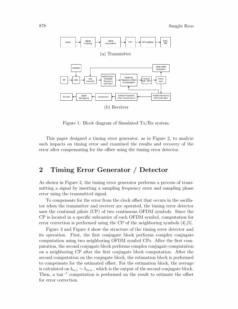
In a system based on this OFDM technique, offset occurs due to the dif-ference of the sampling clock of the oscillator used for the system operation ofthe transmitter and receiver. In order to compensate for the resulting impacts,a timing error detector is used in the receiver [2],[3]. Figure 1 shows the blockdiagram of the simulated transmit system.
878 Sangjin Ryoo
(a) Transmitter
(b) Receiver
Figure 1: Block diagram of Simulated Tx/Rx system.
This paper designed a timing error generator, as in Figure 2, to analyzesuch impacts on timing error and examined the results and recovery of theerror after compensating for the offset using the timing error detector.
2 Timing Error Generator / Detector
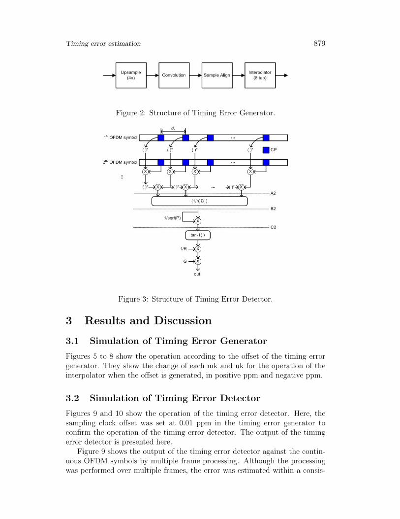
As shown in Figure 2, the timing error generator performs a process of trans-mitting a signal by inserting a sampling frequency error and sampling phaseerror using the transmitted signal.
To compensate for the error from the clock offset that occurs in the oscilla-tor when the transmitter and receiver are operated, the timing error detectoruses the continual pilots (CP) of two continuous OFDM symbols. Since theCP is located in a specific subcarrier of each OFDM symbol, computation forerror correction is performed using the CP of the neighboring symbols [4],[5].
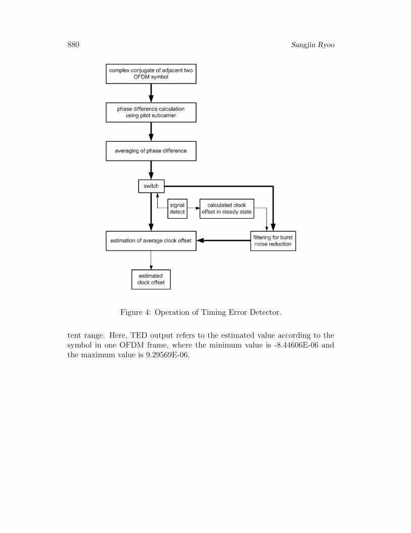
Figure 3 and Figure 4 show the structure of the timing error detector andits operation. First, the first conjugate block performs complex conjugatecomputation using two neighboring OFDM symbol CPs. After the first com-putation, the second conjugate block performs complex conjugate computationon a neighboring CP after the first conjugate block computation. After thesecond computation on the conjugate block, the estimation block is performedto compensate for the estimated offset. For the estimation block, the averageis calculated on bm,1 ∼ bm,n , which is the output of the second conjugate block.Then, a tan−1 computation is performed on the result to estimate the offsetfor error correction.
Timing error estimation 879
Figure 2: Structure of Timing Error Generator.
Figure 3: Structure of Timing Error Detector.
3 Results and Discussion
3.1 Simulation of Timing Error Generator
Figures 5 to 8 show the operation according to the offset of the timing errorgenerator. They show the change of each mk and uk for the operation of theinterpolator when the offset is generated, in positive ppm and negative ppm.
3.2 Simulation of Timing Error Detector
Figures 9 and 10 show the operation of the timing error detector. Here, thesampling clock offset was set at 0.01 ppm in the timing error generator toconfirm the operation of the timing error detector. The output of the timingerror detector is presented here.
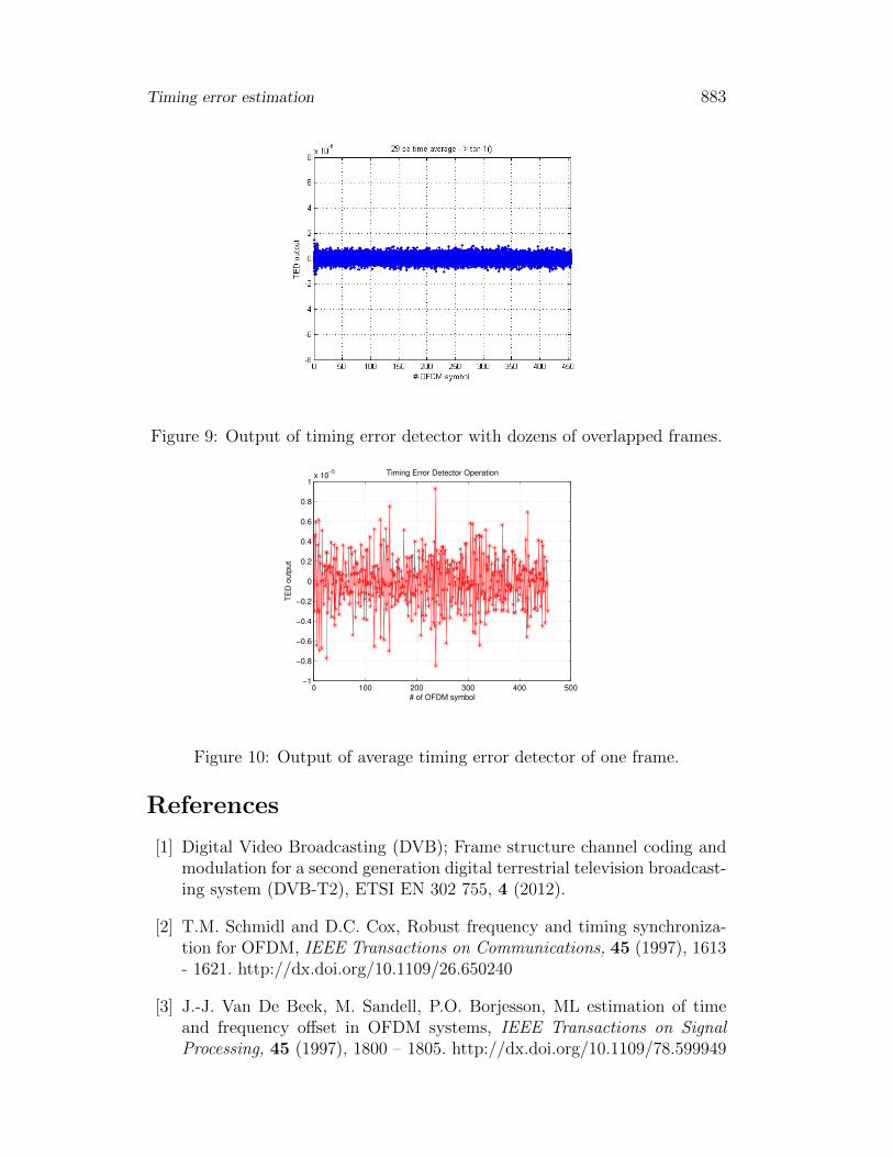
Figure 9 shows the output of the timing error detector against the contin-uous OFDM symbols by multiple frame processing. Although the processingwas performed over multiple frames, the error was estimated within a consis-
880 Sangjin Ryoo
Figure 4: Operation of Timing Error Detector.
tent range. Here, TED output refers to the estimated value according to thesymbol in one OFDM frame, where the minimum value is -8.44606E-06 andthe maximum value is 9.29569E-06.

Timing error estimation 881
0 0.5 1 1.5 2 2.5
x 105
0
0.1
0.2
0.3
0.4
0.5
0.6
0.7
0.8
0.9
1
Sample
Ma
gn
itu
de
TimingError Generator, uk
Figure 5: uk output in case of positive ppm.
0 0.5 1 1.5 2 2.5
x 105
0
0.2
0.4
0.6
0.8
1
1.2
1.4
1.6
1.8
2
Sample
Ma
gn
itu
de
TimingError Generator, mk
Figure 6: mk output in case of positive ppm.
Figure 10 shows the output of the average timing error detector of theframe. In cases of the operation of the symbol unit within one frame, anestimation of around 0.01 ppm on average was confirmed; this is the samplingclock offset.
4 Conclusion
This paper generated a sampling clock offset through a timing error genera-tor in order to compensate for the clock offset in a DVB-T2 system that useshigh-order OFDM. The paper also compared the simulation results accordingto the estimation through the timing error detector. The simulation resultsindicated that the generated sampling clock offset at +10 ppm was capable

882 Sangjin Ryoo
0 0.5 1 1.5 2 2.5
x 105
0
0.1
0.2
0.3
0.4
0.5
0.6
0.7
0.8
0.9
1
Sample
Ma
gn
itu
de
TimingError Generator, uk
Figure 7: uk output in case of negative ppm.
0 0.5 1 1.5 2 2.5
x 105
−3
−2.8
−2.6
−2.4
−2.2
−2
−1.8
−1.6
−1.4
−1.2
−1
Sample
Ma
gn
itu
de
TimingError Generator, mk
Figure 8: mk output in case of negative ppm.
of compensating for the offset resulting from the difference of the samplingclock, and the error was precisely estimated following the set-up offset. It isexpected to be applicable to high-order QAM over 4096 QAM in other broad-casting technology fields in the future.
Timing error estimation 883
Figure 9: Output of timing error detector with dozens of overlapped frames.
0 100 200 300 400 500−1
−0.8
−0.6
−0.4
−0.2
0
0.2
0.4
0.6
0.8
1x 10
−5
# of OFDM symbol
TE
D o
utp
ut
Timing Error Detector Operation
Figure 10: Output of average timing error detector of one frame.
References
[1] Digital Video Broadcasting (DVB); Frame structure channel coding andmodulation for a second generation digital terrestrial television broadcast-ing system (DVB-T2), ETSI EN 302 755, 4 (2012).
[2] T.M. Schmidl and D.C. Cox, Robust frequency and timing synchroniza-tion for OFDM, IEEE Transactions on Communications, 45 (1997), 1613- 1621. http://dx.doi.org/10.1109/26.650240
[3] J.-J. Van De Beek, M. Sandell, P.O. Borjesson, ML estimation of timeand frequency offset in OFDM systems, IEEE Transactions on SignalProcessing, 45 (1997), 1800 – 1805. http://dx.doi.org/10.1109/78.599949
884 Sangjin Ryoo
[4] K.H. Won, J.S. Han, H.J. Choi, Sampling frequency offset estimationmethods for DVB-T/H systems, Journal of Networks, 5 (2010), 313 –320. http://dx.doi.org/10.4304/jnw.5.3.313-320
[5] M. Speth, S.A. Fechtel, G. Fock, H. Meyr, Optimum receiverdesign for wireless broad-band systems using OFDM-part I,IEEE Transactions on Communications, 47 (1999), 1668 – 1677.http://dx.doi.org/10.1109/26.803501
Received: Augsut 6, 2015; Published: September 11, 2015


![OFDM error floor based EVM estimation Error Floor Based EVM Estimation.pdfAWGN source producing the same BER (and EVM) degradation. [1]: The resulting EVM(BER) curves were verified](https://static.fdocuments.us/doc/165x107/5f2e7bc463c3260b31328bb2/ofdm-error-floor-based-evm-estimation-error-floor-based-evm-awgn-source-producing.jpg)