Time of Flight & LiDAR - TI.com
57
Time of Flight & LiDAR: Optical Analog Front End Design Anthony Vaughan High Speed Amplifiers SLYP665
Transcript of Time of Flight & LiDAR - TI.com

Time of Flight & LiDAR: Optical Analog Front End Design
Anthony Vaughan
High Speed Amplifiers
SLYP665

Agenda
2
• Introduction to LiDAR
• Common LiDAR Architectures
• LiDAR Optical Front End Design
• TI LiDAR reference designs & products
• Key discussion points / Q&A

Agenda
3
• Introduction to LiDAR
• Common LiDAR Architectures
• LiDAR Optical Front End Design
• TI LiDAR reference designs & products
• Key discussion points / Q&A
Use the Webex Chat

About Me
4
Anthony Vaughan
• High Speed Amplifier Marketing (Tucson, AZ)
• Joined TI in 2002
– Product/Test Engineering (DSP – Dallas, TX)
– Applications Engineering (MCU - Stafford, TX)
– Marketing (MCU - Stafford, TX)
– Marketing (Precision ADC – Tucson, AZ)
– Marketing (High Speed Amps – Tucson, AZ)
• TI liaison for University of Arizona Autonomous Vehicle Club
• Sponsored several senior design projects at UArizona (LiDAR RC Car)

Introduction to LiDAR
5
LiDAR: Light Detection and Ranging
Automotive LiDAR

Introduction to LiDAR
6
LiDAR: Light Detection and Ranging
Automotive LiDAR
Question: True or False: Cars equipped with
LiDAR based ADAS (Advanced Driver
Assistance Systems) are available to
purchase today. A. True
B. False
Use the Webex polling feature to answer

Introduction to LiDAR
7
LiDAR: Light Detection and Ranging
Automotive LiDAR
Question: True or False: Cars equipped with
LiDAR based ADAS (Advanced Driver
Assistance Systems) are available to
purchase today. A. True
B. False
The Audi A8 is available with an optional
LiDAR system manufactured by Valeo
(Scala® Gen 1).
Image: Audi
Launched 2017
Introduction to LiDAR
8
LiDAR: Light Detection and Ranging
Automotive LiDAR
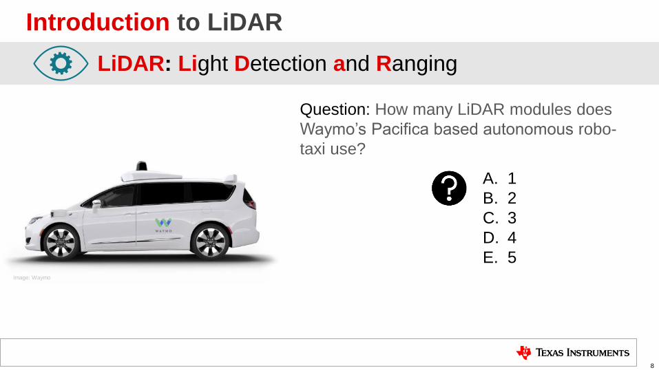
Question: How many LiDAR modules does
Waymo’s Pacifica based autonomous robo-
taxi use?
A. 1
B. 2
C. 3
D. 4
E. 5 Image: Waymo

Introduction to LiDAR
9
LiDAR: Light Detection and Ranging
Automotive LiDAR
Question: How many LiDAR modules does
Waymo’s Pacifica based autonomous robo-
taxi use?
A. 1
B. 2
C. 3
D. 4
E. 5 Image: Waymo
There are 4 short range LiDAR and 1
medium range LiDAR modules.

Introduction to LiDAR
10
LiDAR: Light Detection and Ranging
Automotive LiDAR
Question: True or False: Tesla’s Autopilot 2
system uses the world’s highest resolution
LiDAR sensor.
A. True
B. False
Image: Tesla

Introduction to LiDAR
11
LiDAR: Light Detection and Ranging
Automotive LiDAR
Question: True or False: Tesla’s Autopilot 2
system uses the world’s highest resolution
LiDAR sensor.
Image: Tesla
A. True
B. False
The Tesla Autopilot system does
not use LiDAR.

Introduction to LiDAR
12
LiDAR: Light Detection and Ranging
Lidar vs LiDAR vs LIDAR
Which one is correct

Introduction to LiDAR
13
LiDAR: Light Detection and Ranging
Lidar vs LiDAR vs LIDAR
Which one is correct
Evolution from acronym to word

Introduction to LiDAR
14
LiDAR: Light Detection and Ranging
Lidar vs LiDAR vs LIDAR
Which one is correct
Evolution from acronym to word
RADAR: RAdio Detection And Ranging
This has happened before:

Introduction to LiDAR
15
LiDAR: Light Detection and Ranging
Lidar vs LiDAR vs LIDAR
Which one is correct
What about LADAR
LADAR: Laser Detection and Ranging

Introduction to LiDAR
16
LiDAR: Light Detection and Ranging
Lidar vs LiDAR vs LIDAR
Which one is correct
What about LADAR
LADAR: Laser Detection and Ranging
light amplification by stimulated emission of radiation

Why do we need LiDAR?
17
Myth: Sonar, Radar & Cameras are adequate
Sonar
Advantages
Disadvantages •Low resolution
•Limited range
•Slow response
• Inexpensive
•Works in all
lighting conditions
Radar
Advantages
Disadvantages •Medium resolution
•Medium response
•Long range
•Works in most
lighting & weather
conditions
Camera
Advantages
Disadvantages •Poor distance measurement
•Poor low light performance
•Can be blinded with bright
ambient light or bad weather
•High Resolution
•Can determine colors
• Inexpensive imagers
Why do we need LiDAR?
18
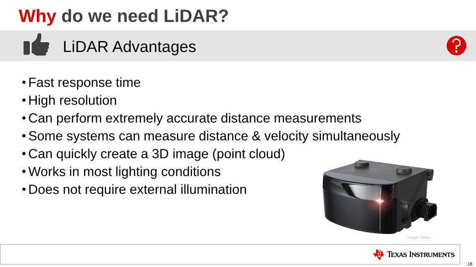
LiDAR Advantages
• Fast response time
• High resolution
• Can perform extremely accurate distance measurements
• Some systems can measure distance & velocity simultaneously
• Can quickly create a 3D image (point cloud)
• Works in most lighting conditions
• Does not require external illumination
Image: Valeo

Why do we need LiDAR?
19
LiDAR Disadvantages
• High cost (prices are coming down quickly)
• Limited distance (ranges are increasing)
• Poor performance in bad weather
• Some systems can have poor performance in bright sun light
Image: Valeo

Why do we need LiDAR?
20
LiDAR Disadvantages
• High cost (prices are coming down quickly)
• Limited distance (ranges are increasing)
• Poor performance in bad weather
• Some systems can have poor performance in bright sun light
Image: Valeo
LiDAR will augment radar/camera/sonar in most
automotive driver assistance systems.
+

Basic LiDAR Principles
21
Optical
Time of Flight
(ToF)
System
TX
RX
Object LiDAR
Pulsed Time of Flight (ToF)

Basic LiDAR Principles
22
Optical
Time of Flight
(ToF)
System
TX
RX
Object LiDAR Laser Transmitter
Pulsed Time of Flight (ToF)

Basic LiDAR Principles
23
TX
RX
Object
Optical
Time of Flight
(ToF)
System
LiDAR
Optical Receiver
Pulsed Time of Flight (ToF)

Basic LiDAR Principles
24
TX
RX
Object
Optical
Time of Flight
(ToF)
System
Start
LiDAR
Pulsed Time of Flight (ToF)

Basic LiDAR Principles
25
RX
Object
Optical
Time of Flight
(ToF)
System
TX
Stop
LiDAR
Pulsed Time of Flight (ToF)

Basic LiDAR Principles
26
RX
Object
Optical
Time of Flight
(ToF)
System
TX
LiDAR
𝑑 =𝑐 𝑡
2
𝑑𝑖𝑠𝑡𝑎𝑛𝑐𝑒 𝑑
𝑡𝑖𝑚𝑒 𝑡
𝑠𝑝𝑒𝑒𝑑 𝑜𝑓 𝑙𝑖𝑔ℎ𝑡 𝑐
Pulsed Time of Flight (ToF)

Common LiDAR Ranging Architectures
27
Pulsed Time of Flight
Phase Shift
Frequency Modulation
RX
TX
Pulsed Time of Flight takes a measurement of the time
it takes a pulse of light to go from the transmitter to an
object and back to the receiver.
Phase Shift uses a continuous wave and measures the
time of flight as a phase shift. The maximum distance is
limited by phase wrapping. RX
TX
∆
RX
TX Frequency modulation (FMCW) uses a continuous wave
with varying frequency and measures the time of flight as a
frequency difference. Distance & velocity can be measured.
Freq
Time

Laser Transmitter Types
28
Optical
Time of Flight
(ToF)
System
TX
RX
LiDAR Laser Transmitter
Edge Emitting Lasers (EEL):
Vertical Cavity Surface Emitting Laser (VCSEL):
Very mature technology that can provide very high
power transmission. A wide variety of wavelengths
are available. 830nm – 940nm & 1550nm
Newer technology that allow reduced cost
manufacture of array transmitters. A wide variety of
wavelengths are available. 830nm – 940nm & 1550nm

Laser Receiver Types
29
Optical
Time of Flight
(ToF)
System
LiDAR Pin Photo Diode:
Avalanche Photo Diode (APD):
Very mature technology that converts light in to an electrical
current.
Newer photo diode technology that requires a high reverse
bias for operation. APDs can provide very high gain due to the
avalanche multiplication of the holes and electrons created by
the photon/light.
RX
Optical Receiver
TX
Single Photon Avalanche Diode (SPAD): Similar to APDs, but SPADs are designed to operate with a
reverse bias voltage higher than the junction breakdown
voltage providing even higher gain.
Silicon Photomultiplier (SiPM): SiPMs provide very high sensitivity and dynamic range. They
are made up of SPADs on a common silicon substrate

Scanning LiDAR
30
Scanning LiDAR is currently the most common LiDAR implementation

Scanning LiDAR
31
Automotive LiDAR
Most multi-channel scanning LiDAR systems need to scan either
horizontally, vertically or both.
Horizonal Scanning
Scanning Laser
Vertical Scanning
Scannin
g L
aser

Scanning LiDAR
32
Automotive LiDAR
Some mechanically scanning LiDAR systems scan in a circle to provide
a 360-degree view.
360º Scanning
Scanning
Scanning
Laser
Laser

Scanning LiDAR
33
There are several different methods to implement scanning LiDAR.
Scanning
Scanning
Scanning LiDAR Methods:
Mechanical Scanning:
• Macro-mechanical
• Micro-motion
• Prisms
Solid State Scanning:
• MEMS
• Electro-optical
• Optical phased array
Flash LiDAR
34
Flash LiDAR is another implementation that does not require any
moving parts.

Flash LiDAR
35
Flash LiDAR illuminates the entire scene and uses an array of
photodetectors to form an image.
Flash Illumination
Fla
sh Illum
ination

Flash LiDAR
36
Several types of photodetectors can be used in Flash LiDAR systems.
Fla
sh Illum
ination
Flash LiDAR Photodetectors:
• Pin Diode Array
• Avalanche Photodiode Array
• SPAD Array
• Silicon Photomultiplier (SiPM)
• CCD Imager w/ ToF
• CMOS Imager w/ ToF

Po
int
Clo
ud
Laser
Control Laser
Driver
Laser
Photo
Diode
ADC
Texas Instruments manufactures several products used in the LiDAR signal chain: • Receive Path: Transimpedance amplifier, ADC Driver, ADC
• Transmit Path: Laser Driver
• Processing: Time of Flight Processing
ADC
Time of Flight
Processing
Automotive LiDAR System Block Diagram
TIA ADC
Driver
37

Po
int
Clo
ud
Laser
Control Laser
Driver
Laser
Photo
Diode
ADC ADC
Time of Flight
Processing
Automotive LiDAR System Block Diagram
TIA ADC
Driver
38
Texas Instruments manufactures several products used in the LiDAR signal chain: • Receive Path: Transimpedance amplifier, ADC Driver, ADC
• Transmit Path: Laser Driver
• Processing: Time of Flight Processing
Receive Path

Texas Instruments LiDAR & Optical Time of Flight (ToF)
Transimpedance
Amplifier(s)
Fully-Differential
Amplifier
ADC FPGA
Analog-to-Digital
Converter
Channel 1
Channel N
VREF
MUX
1
N
OUT
Digital
Processing
Automotive LiDAR
High-speed optical front end with Analog to Digital Converter (ADC)
High-speed optical front end with Time-to-Digital Converter (TDC)
+
- ADC Processor
Transimpedance
Amplifier(s)
Fully-Differential
Amplifier
FPGA /
μController
Comparator or
Time-to-Digital
Converter
Channel 1
Channel N
VREF
MUX
1
N
OUT
Digital
Processing
TDC Processor +
-
2 Optical ToF Receive Path Architectures: 1
2
Featured TI Devices: TIAs: OPA855, OPA857, OPA858
FDAs: THS4541
TIA + FDA: LMH32401
ADCs: ADC3244, ADC12QJ1600
Processors: TDA2, TDA3
Featured TI Devices: TIAs: OPA855, OPA857, OPA858
FDAs: THS4541
TIA + FDA: LMH32401
TDC: TDC7201
Processors: MSP430, C2000
(TIAs) (FDA)
(TIAs) (FDA)
39

LiDAR Time of Flight System TDC Based Diagram
MSP430 Microcontroller
LaunchPad™
OPA858 TLV3501
Laser Driver
TDC7201 Time to Digital
Converter
OPA858 Transimpedance Amplifier
• High Gain Bandwidth Product: 5.5 GHz
• Ultra-Low Bias Current Input: 10 pA
• Low Input Voltage Noise: 2.5 nV/√ Hz
• Slew rate: 2000 V/μs
• Supply Voltage Range: 3.3 V to 5.25 V
• Small Package: 8-Pin WSON (2mm x 2mm)
• Temperature Range: -40°C to +125°C
40

• Optical front-end design with demonstrated time-of-flight(ToF)
measurement.
• High-speed amplifier signal path with bandwidth greater than
200 MHz at gain = 10 kΩ.
• Centimeter level measurement accuracy.
• High-speed transimpedance amplifier (TIA) for I-to-V conversion
• High-speed time-to-digital converter & low power MCU/processor
Applications
• Laser Distance Measurement
• LiDAR
• 3D Scanning
• EPOS
• Machine Vision
• Vacuum Robots
• Drone Vision
• OTDR
• High speed transimpedance amplifier provides the closed loop
bandwidth and gain sufficient for optical ToF applications.
• Low power/cost digital processing & control provides an efficient
platform for highly accurate distance measurements.
• PC interface software provides quick and easy method to evaluate
system performance and distance measurements.
Features Benefits
Applications
Tools & Resources • TIDA-060025 Web Site
‒ User Guide
• Device Datasheets: ‒ OPA858
‒ TDC7201
‒ TLV3501
‒ MSP430 MCU
Watch the Overview Video
TIDA-060025 System Block Diagram
TIDA-060025 Maximizing Transimpedance Bandwidth for LIDAR and ToF
41

+
-
DAC5682Z 500 MSPS,
16-Bit DAC
TIA
TIA
+
-
+
-
125 MSPS 14-Bit ADC,
Ref Ch
125 MSPS 14-Bit ADC,
Return Ch
TS
W1
400
Contr
olle
r B
oard
TS
W1
400
Contr
olle
r B
oard
Digital to Analog Converters:
Analog to Digital Converters:
High Speed Amplifiers:
DAC5682Z
• 1 GSPS
• 16-Bit Resolution
ADC3244
• 2 Channel, 125 MSPS
• 14-Bit Resolution
OPA695
• 1.7 GHz, Current-Feedback Amplifier
OPA857
• Integrated Transimpedance Amplifier
THS4541
• 850 MHz, Fully Differential Amplifier
LiDAR Time of Flight System ADC Based Diagram
42

TIDA-01187 LIDAR-Pulsed Time-of-Flight Reference Design
• Measurement Range: 1.5 m to 9 m
• Range Measurement Mean Error of < ±6 mm and StdDev of < 3 cm
• 5.75W Pulsed 905 nm Laser Diode & Driver with < 1mW Average
Power
• PIN Photodiode High Speed Transimpedance Amp Front End
• 125 MSPS 14-bit ADC and 500 MSPS 16-bit DAC Signal Chains
• Laser Collimation and Photoreceiver Focusing Optics
• Pulsed ToF Measurement Method with DFT based Range Estimation
Applications
Laser Safety Scanners and Range Finders (LiDAR)
Architectural Surveying Equipment
Automotive ADAS, Drones & Robotics
Retinal Imaging
• High resolution ADC simplifies front end circuitry
• Eliminates variable gain amplifiers (VGA) and time
discriminators
• ADC improves performance over comparator solutions while
keeping power low
• Improved Resolution
• Elimination of Walk
• Target Detection
Features Benefits
Applications
Tools & Resources • TIDA-01187 Web Site
‒ User Guide
• Device Datasheets: ‒ ADC3244
‒ DAC5682Z
‒ OPA857
‒ THS4541
‒ OPA695
Watch the Overview Video 43

OPA85x Device Family Comparison
Name Input Type Gain BW Stable Gain Applications Benefit
OPA855 Bipolar 8.0 GHz 7 V/V Best noise at lower gains
Highest bandwidth possible
OPA856 Bipolar 1.2 GHz (BW) Unity Unity gain suitable for clamping
Good noise performance for low gains
OPA857 FET 130MHz closed loop @ 5kΩ
105MHz closed loop @ 20kΩ
Integrated gain settings for 5kΩ
and 20kΩ transimpedance gains
OPA858 FET 5.5 GHz 7 V/V Best noise performance at high gains
High bandwidth and low input current
OPA859 FET 900 MHz (BW) Unity Maximum application flexibility
Good high gain noise performance
Production
Coming Soon!
Production
Production
Production Q100
Q100
Q100
AEC Q100 automotive devices in development
44
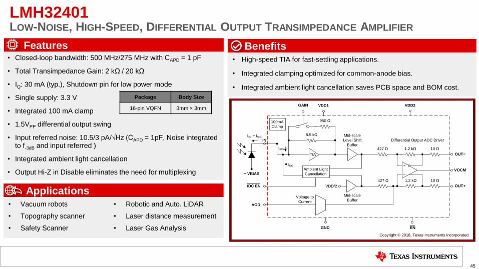
LMH32401 LOW-NOISE, HIGH-SPEED, DIFFERENTIAL OUTPUT TRANSIMPEDANCE AMPLIFIER
Features
• High-speed TIA for fast-settling applications.
• Integrated clamping optimized for common-anode bias.
• Integrated ambient light cancellation saves PCB space and BOM cost.
Benefits
Applications • Vacuum robots
• Topography scanner
• Safety Scanner
• Robotic and Auto. LiDAR
• Laser distance measurement
• Laser Gas Analysis
• Closed-loop bandwidth: 500 MHz/275 MHz with CAPD = 1 pF
• Total Transimpedance Gain: 2 kΩ / 20 kΩ
• IQ: 30 mA (typ.), Shutdown pin for low power mode
• Single supply: 3.3 V
• Integrated 100 mA clamp
• 1.5VPP differential output swing
• Input referred noise: 10.5/3 pA/√Hz (CAPD = 1pF, Noise integrated to f-3dB and input referred )
• Integrated ambient light cancellation
• Output Hi-Z in Disable eliminates the need for multiplexing
Package Body Size
16-pin VQFN 3mm × 3mm
8.5 kΩ
TIA
950 Ω
Mid-scale
Level Shift
Buffer
Ambient Light
Cancellation
IDC
427 Ω
Mid-scale
Buffer
427 Ω
+
–
1.2 kΩ
1.2 kΩ
10 Ω
10 Ω
Voltage to
Current
VDD/2
100mA
Clamp
ISIG
IDC EN
VOD
IN
VOCM
OUT+
OUT−
GAIN VDD1 VDD2
GND EN
− VBIAS
Differential Output ADC Driver
Copyright © 2018, Texas Instruments Incorporated
IDC + ISIG
45

8.5 kΩ
TIA
850 Ω
Mid-scale
Level Shift
Buffer
Ambient Light
Cancellation
IDC
427 Ω
Mid-scale
Buffer
427 Ω
+
–
1.2 kΩ
1.2 kΩ
10 Ω
10 Ω
Voltage to
Current
VDD/2
100mA
Clamp
ISIG
LMH32401
IDC EN
VOD (0.4V)
IN
VOCM (1.1V)
OUT+
OUT−
GAIN VDD1 (3.3V)
GND EN
− VBIAS
Differential Output ADC DriverIDC + ISIG
VDD2 (3.3V)
33.2 Ω
33.2 Ω
ADC12QJ1600-Q1
50
Ω5
0 Ω
ADC A
VA11 (1.1V)
VREFBG (1.1V)
22 kΩ
12
.5 k
Ω
+
–
(0.4V)
INA+
INA−
VA19 (1.9V) VD11 (1.1V)
Low-pass filter
(Optional)
LMH32401 & ADC12QJ1600 Receive Path Solution
4-ch 12-bit 1.6-GSPS ADC
46
TIA
+
- ADC A
100mA
Current
Clamp
Ambient Light
Cancelation
VREF

8.5 kΩ
TIA
850 Ω
Mid-scale
Level Shift
Buffer
Ambient Light
Cancellation
IDC
427 Ω
Mid-scale
Buffer
427 Ω
+
–
1.2 kΩ
1.2 kΩ
10 Ω
10 Ω
Voltage to
Current
VDD/2
100mA
Clamp
ISIG
LMH32401
IDC EN
VOD (0.4V)
IN
VOCM (1.1V)
OUT+
OUT−
GAIN VDD1 (3.3V)
GND EN
− VBIAS
Differential Output ADC DriverIDC + ISIG
VDD2 (3.3V)
33.2 Ω
33.2 Ω
ADC12QJ1600-Q1
50
Ω5
0 Ω
ADC A
VA11 (1.1V)
VREFBG (1.1V)
22 kΩ
12
.5 k
Ω
+
–
(0.4V)
INA+
INA−
VA19 (1.9V) VD11 (1.1V)
Low-pass filter
(Optional)
LMH32401 & ADC12QJ1600 Receive Path Solution
4-ch 12-bit 1.6-GSPS ADC
47
TIA
+
- ADC A
100mA
Current
Clamp
Ambient Light
Cancelation
VREF
Maximize the signal dynamic
range with the VOD pin

LMH32401 VOD Input to Maximize Dynamic Range
48
VOD = 0V VOD = 0.4V

ADC AINA+
INA–
ADC BINB+
INB–
ADC CINC+
INC–
ADC DIND+
IND–
TMSTP+
TMSTP–
JESD204B/C
SYNCSE\
D0+
D0–
D7+
D7–
TRIGOUT+
TRIGOUT–
CLK_SE
SYSREF+
SYSREF–
PLL+VCO
Timestamp Insertion
Timestamp Insertion
Timestamp Insertion
Timestamp Insertion
Status Indicators
OVRA
OVRB
OVRC
OVRD
Calibration Controller
CALTRIG
CALSTAT
PLLREFO+
PLLREFO–
÷
CLK+
CLK–
SYSREF Windowing
Clock Control
PLLEN
PLLREFSE
SerDes PLL
To synchronization logic
÷
÷
CLKCFG0
CLKCFG1
• ADC Core: Quad 12-bit 1.6 Gsps
• Non-Interleaved ADC core: No interleaving spurs
• Internal Dither: Improved high-order spurs, backoff performance
• Power Consumption: 1.9 W total (1 Gsps, PLL disabled)
• Integrated PLL and VCO: Simplified system clocking architecture
• Buffered Inputs: 6-GHz Input Bandwidth (-3 dB)
• Input Full-Scale Voltage: 0.8 Vpp (Adjustable, 0.5 Vpp to 1.0 Vpp)
• SNR @ 100 MHz: 56.8 dBFS (800 mVpp)
• ENOB @ 100 MHz: 9.1-bit
• Code-Error Rate: 10-18
• Digital Interface: JESD204B/C with subclass 1 support
• Serdes Lanes and Speeds: Up to 8 lanes @ up to 17.16 Gbps
• Reduced Resolution Options: 10-bit and 8-bit options available to reduce
interface speed or number of lanes
• Timestamp and Trigger Output: Reduce system complexity and retime trigger
signals to internal sampling clock
• Power supplies: 1.1V, 1.9V
• Package: BGA (10x10mm, 0.8mm pitch)
• Automotive Qualification: AEC-Q100 Grade 1 (-40 to 150°C)
Features
ADC12QJ1600/800-Q1 12-Bit, Quad Channel, 1.6 Gsps ADC
Input Frequency (@ 1.6 Gsps, -1 dBFS) 100 MHz 1 GHz
SNR (dBFS, typ) 56.8 55.7
NSD (dBFS/Hz, typ) -145.8 -144.7
SFDR (dBc, typ) 72 65
Non HD2,3 (dBc, typ) 75 70

ADC AINA+
INA–
TMSTP+
TMSTP–
JESD204B/C
SYNCSE\
D0+
D0–
D3+
D3–
TRIGOUT+
TRIGOUT–
CLK_SE
SYSREF+
SYSREF–
PLL+VCO
Timestamp Insertion
Status Indicators
OVRA
OVRC
OVRD
Calibration Controller
CALTRIG
CALSTAT
PLLREFO+
PLLREFO–
÷
CLK+
CLK–
SYSREF Windowing
Clock Control
PLLEN
PLLREFSE
SerDes PLL
To synchronization logic
÷
÷
CLKCFG0
CLKCFG1
• ADC Core: Single 12-bit 1.6 Gsps
• Non-Interleaved ADC core: No interleaving spurs
• Internal Dither: Improved high-order spurs, backoff performance
• Power Consumption: 900 mW total (1 Gsps, PLL disabled)
• Integrated PLL and VCO: Simplified system clocking architecture
• Buffered Inputs: 6-GHz Input Bandwidth (-3 dB)
• Input Full-Scale Voltage: 0.8 Vpp (Adjustable, 0.5 Vpp to 1.0 Vpp)
• SNR @ 100 MHz: 56.8 dBFS (800 mVpp)
• ENOB @ 100 MHz: 9.1-bit
• Code-Error Rate: 10-18
• Digital Interface: JESD204B/C with subclass 1 support
• Serdes Lanes and Speeds: Up to 4 lanes @ up to 17.16 Gbps
• Reduced Resolution Options: 10-bit and 8-bit options available to reduce
interface speed or number of lanes
• Timestamp and Trigger Output: Reduce system complexity and retime trigger
signals to internal sampling clock
• Power supplies: 1.1V, 1.9V
• Package: BGA (10x10mm, 0.8mm pitch)
• Automotive Qualification: AEC-Q100 Grade 1 (-40 to 150°C)
Features
ADC12SJ1600/800-Q1 12-Bit, Single Channel, 1.6 Gsps ADC
Input Frequency (@ 1.6 Gsps, -1 dBFS) 100 MHz 1 GHz
SNR (dBFS, typ) 56.8 55.7
NSD (dBFS/Hz, typ) -145.8 -144.7
SFDR (dBc, typ) 72 65
Non HD2,3 (dBc, typ) 75 70

Po
int
Clo
ud
Laser
Control Laser
Driver
Laser
Photo
Diode
ADC ADC
Time of Flight
Processing
Automotive LiDAR System Block Diagram
TIA ADC
Driver
51
Texas Instruments manufactures several products used in the LiDAR signal chain: • Receive Path: Transimpedance amplifier, ADC Driver, ADC
• Transmit Path: Laser Driver - LMG1025-Q1
• Processing: Time of Flight Processing
Transmit Path

LMG1025-Q1: Automotive Low Side Driver For High Frequency, Narrow Pulse Applications
Features
Applications
Narrow pulse width allows increase in power/current level while still
maintaining eye safety
Switches at Frequencies needed for LED Drive in LiDAR
Independent outputs allow for setting up different rise and fall time as
required by the application
Small distortion enables precise image mapping
Small, leadless package enables layout optimization
AEC-Q100 Grade 1 Qualification
Capable of operating at very high switching frequency
Independent pull-up (7A) and pull-down (5A) outputs
Typical rise time of 650ps, fall time of 850ps
Typical minimum input pulse width of 1.25 ns
Typical propagation delay of 2.9ns
Single 5V supply & under-voltage protection (UVLO)
Inverting and non-inverting inputs
Benefits
LiDAR
3D ToF Laser Drivers
Occupant Monitoring
Application Diagram & Package Options
52

Po
int
Clo
ud
Laser
Control Laser
Driver
Laser
Photo
Diode
ADC ADC
Time of Flight
Processing
Automotive LiDAR System Block Diagram
TIA ADC
Driver
53
Texas Instruments manufactures several products used in the LiDAR signal chain: • Receive Path: Transimpedance amplifier, ADC Driver, ADC
• Transmit Path: Laser Driver - LMG1025-Q1
• Processing: Time of Flight Processing: TDA2, TDA3
Processing

54
Automotive LiDAR Time of Flight & LiDAR: Optical Analog Front End Design
Questions & Answers

55
References
Images:
Valeo Scala: https://www.valeo.com/en/valeo-scala/
Tesla Model S: https://pod-point.com/guides/vehicles/tesla/2019/model-s
Waymo Pacifica: https://waymo.com/open/
Audi A8: https://www1.drivingvisionnews.com/pdf/lidar/Valeo.pdf
Technical Content: LIDAR vs Radar vs Sonar: Which Is Better for Self-Driving Cars?, Vasyl Tsyktor, https://cyberpulse.info/lidar-vs-radar-vs-sonar/
Lidar vs. LiDAR vs. LIDAR vs. LADAR: Letter Case Matters, Word Press, https://geozoneblog.wordpress.com/2014/04/09/lidar-case-matters/
LiDAR industry: high expectations for autonomous driving: Yole Market Research, http://www.yole.fr/Lidar_Market_Status.aspx#.XsQIwsZ7nu0

SLYP665

IMPORTANT NOTICE AND DISCLAIMER
TI PROVIDES TECHNICAL AND RELIABILITY DATA (INCLUDING DATASHEETS), DESIGN RESOURCES (INCLUDING REFERENCE DESIGNS), APPLICATION OR OTHER DESIGN ADVICE, WEB TOOLS, SAFETY INFORMATION, AND OTHER RESOURCES “AS IS” AND WITH ALL FAULTS, AND DISCLAIMS ALL WARRANTIES, EXPRESS AND IMPLIED, INCLUDING WITHOUT LIMITATION ANY IMPLIED WARRANTIES OF MERCHANTABILITY, FITNESS FOR A PARTICULAR PURPOSE OR NON-INFRINGEMENT OF THIRD PARTY INTELLECTUAL PROPERTY RIGHTS.These resources are intended for skilled developers designing with TI products. You are solely responsible for (1) selecting the appropriate TI products for your application, (2) designing, validating and testing your application, and (3) ensuring your application meets applicable standards, and any other safety, security, or other requirements. These resources are subject to change without notice. TI grants you permission to use these resources only for development of an application that uses the TI products described in the resource. Other reproduction and display of these resources is prohibited. No license is granted to any other TI intellectual property right or to any third party intellectual property right. TI disclaims responsibility for, and you will fully indemnify TI and its representatives against, any claims, damages, costs, losses, and liabilities arising out of your use of these resources.TI’s products are provided subject to TI’s Terms of Sale (www.ti.com/legal/termsofsale.html) or other applicable terms available either on ti.com or provided in conjunction with such TI products. TI’s provision of these resources does not expand or otherwise alter TI’s applicable warranties or warranty disclaimers for TI products.
Mailing Address: Texas Instruments, Post Office Box 655303, Dallas, Texas 75265Copyright © 2020, Texas Instruments Incorporated