Time constant calculations - · PDF filepoints in time: • 1 time constant (τ) after...
58
Time constant calculations This worksheet and all related files are licensed under the Creative Commons Attribution License, version 1.0. To view a copy of this license, visit http://creativecommons.org/licenses/by/1.0/, or send a letter to Creative Commons, 559 Nathan Abbott Way, Stanford, California 94305, USA. The terms and conditions of this license allow for free copying, distribution, and/or modification of all licensed works by the general public. Resources and methods for learning about these subjects (list a few here, in preparation for your research): 1
Transcript of Time constant calculations - · PDF filepoints in time: • 1 time constant (τ) after...

Time constant calculations
This worksheet and all related files are licensed under the Creative Commons Attribution License,version 1.0. To view a copy of this license, visit http://creativecommons.org/licenses/by/1.0/, or send aletter to Creative Commons, 559 Nathan Abbott Way, Stanford, California 94305, USA. The terms andconditions of this license allow for free copying, distribution, and/or modification of all licensed works bythe general public.
Resources and methods for learning about these subjects (list a few here, in preparation for yourresearch):
1
Questions
Question 1
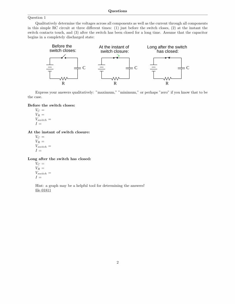
Qualitatively determine the voltages across all components as well as the current through all componentsin this simple RC circuit at three different times: (1) just before the switch closes, (2) at the instant theswitch contacts touch, and (3) after the switch has been closed for a long time. Assume that the capacitorbegins in a completely discharged state:
R
C
R
C
switch closes:Before the At the instant of
switch closure:
R
C
has closed:Long after the switch
Express your answers qualitatively: ”maximum,” ”minimum,” or perhaps ”zero” if you know that to bethe case.
Before the switch closes:
VC =VR =Vswitch =I =
At the instant of switch closure:
VC =VR =Vswitch =I =
Long after the switch has closed:
VC =VR =Vswitch =I =
Hint: a graph may be a helpful tool for determining the answers!file 01811
2
Question 2
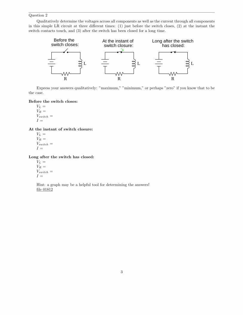
Qualitatively determine the voltages across all components as well as the current through all componentsin this simple LR circuit at three different times: (1) just before the switch closes, (2) at the instant theswitch contacts touch, and (3) after the switch has been closed for a long time.
R R
switch closes:Before the At the instant of
switch closure:
R
has closed:Long after the switch
LLL
Express your answers qualitatively: ”maximum,” ”minimum,” or perhaps ”zero” if you know that to bethe case.
Before the switch closes:
VL =VR =Vswitch =I =
At the instant of switch closure:
VL =VR =Vswitch =I =
Long after the switch has closed:
VL =VR =Vswitch =I =
Hint: a graph may be a helpful tool for determining the answers!file 01812
3

Question 3
Calculate the final value of current through the inductor with the switch in the left-hand position(assuming that many time constants’ worth of time have passed):
10 V
5 kΩ 91 kΩ
Now, assume that the switch is instantly moved to the right-hand position. How much voltage will theinductor initially drop?
10 V
5 kΩ 91 kΩ
Explain why this voltage is so very different from the supply voltage. What practical uses might acircuit such as this have?
file 01808
Question 4
Suppose a capacitor is charged to a voltage of exactly 100 volts, then connected to a resistor so itdischarges slowly. Calculate the amount of voltage remaining across the capacitor terminals at the followingpoints in time:
• 1 time constant (τ) after connecting the resistor:• 2 time constants (2τ) after connecting the resistor:• 3 time constants (3τ) after connecting the resistor:• 4 time constants (4τ) after connecting the resistor:• 5 time constants (5τ) after connecting the resistor:
file 03551
4

Question 5
Determine the number of time constants (τ) that 7.5 seconds is equal to in each of the following reactivecircuits:
• RC circuit; R = 10 kΩ, C = 220 µF ; 7.5 sec =• RC circuit; R = 33 kΩ, C = 470 µF ; 7.5 sec =• RC circuit; R = 1.5 kΩ, C = 100 µF ; 7.5 sec =• RC circuit; R = 790 Ω, C = 9240 nF ; 7.5 sec =• RC circuit; R = 100 kΩ, C = 33 pF ; 7.5 sec =
• LR circuit; R = 100 Ω, L = 50 mH ; 7.5 sec =• LR circuit; R = 45 Ω, L = 2.2 H ; 7.5 sec =• LR circuit; R = 1 kΩ, L = 725 mH ; 7.5 sec =• LR circuit; R = 4.7 kΩ, L = 325 mH ; 7.5 sec =• LR circuit; R = 6.2 Ω, L = 25 H ; 7.5 sec =
file 01802
Question 6
Re-write this mathematical expression so that the exponent term (−x) is no longer negative:
e−x
Also, describe the calculator keystroke sequence you would have to go through to evaluate this expressiongiven any particular value for x.
file 01803
5

Question 7
The decay of a variable (either voltage or current) in a time-constant circuit (RC or LR) follows thismathematical expression:
e−t
τ
Where,e = Euler’s constant (≈ 2.718281828)t = Time, in secondsτ = Time constant of circuit, in seconds
Calculate the value of this expression as t increases, given a circuit time constant (τ) of 1 second.Express this value as a percentage:
t = 1 secondt = 2 secondst = 3 secondst = 4 secondst = 5 secondst = 6 secondst = 7 secondst = 8 secondst = 9 secondst = 10 seconds
Based on your calculations, how would you describe the change in the expression’s value over time as t
increases?file 00442
6
Question 8
The decay of a variable (either voltage or current) in a time-constant circuit (RC or LR) follows thismathematical expression:
e−t
τ
Where,e = Euler’s constant (≈ 2.718281828)t = Time, in secondsτ = Time constant of circuit, in seconds
Calculate the value of this expression as t increases, given a circuit time constant (τ) of 2 seconds.Express this value as a percentage:
t = 1 secondt = 2 secondst = 3 secondst = 4 secondst = 5 secondst = 6 secondst = 7 secondst = 8 secondst = 9 secondst = 10 seconds
Also, express the percentage value of any increasing variables (either voltage or current) in an RC orLR charging circuit, for the same conditions (same times, same time constant).
file 00450
Question 9
At a party, you happen to notice a mathematician taking notes while looking over the food table whereseveral pizzas are set. Walking up to her, you ask what she is doing. ”I’m mathematically modeling theconsumption of pizza,” she tells you. Before you have the chance to ask another question, she sets hernotepad down on the table and excuses herself to go use the bathroom.
Looking at the notepad, you see the following equation:
Percentage =(
e−t
6.1
)
× 100%
Where,t = Time in minutes since arrival of pizza.
The problem is, you don’t know whether the equation she wrote describes the percentage of pizza eatenor the percentage of pizza remaining on the table. Explain how you would determine which percentage thisequation describes. How, exactly, can you tell if this equation describes the amount of pizza already eatenor the amount of pizza that remains to be eaten?
file 03549
7
Question 10
At a party, you happen to notice a mathematician taking notes while looking over the food table whereseveral pizzas are set. Walking up to her, you ask what she is doing. ”I’m mathematically modeling theconsumption of pizza,” she tells you. Before you have the chance to ask another question, she sets hernotepad down on the table and excuses herself to go use the bathroom.
Looking at the notepad, you see the following equation:
Percentage =(
1 − e−t
5.8
)
× 100%
Where,t = Time in minutes since arrival of pizza.
The problem is, you don’t know whether the equation she wrote describes the percentage of pizza eatenor the percentage of pizza remaining on the table. Explain how you would determine which percentage thisequation describes. How, exactly, can you tell if this equation describes the amount of pizza already eatenor the amount of pizza that remains to be eaten?
file 03309
Question 11
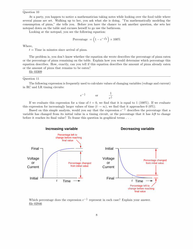
The following expression is frequently used to calculate values of changing variables (voltage and current)in RC and LR timing circuits:
e−t
τ or1
et
τ
If we evaluate this expression for a time of t = 0, we find that it is equal to 1 (100%). If we evaluatethis expression for increasingly larger values of time (t → ∞), we find that it approaches 0 (0%).
Based on this simple analysis, would you say that the expression e−t
τ describes the percentage that avariable has changed from its initial value in a timing circuit, or the percentage that it has left to changebefore it reaches its final value? To frame this question in graphical terms . . .
TimeInitial
Final
t
Voltageor
CurrentPercentage changed
from initial value
Percentage left tochange before reaching
final value
TimeFinal
t
Voltageor
Current
Percentage changedfrom initial value
Percentage left tochange before reaching
final value
Initial
Increasing variable Decreasing variable
Which percentage does the expression e−t
τ represent in each case? Explain your answer.file 02946
8

Question 12
The following two expressions are frequently used to calculate values of changing variables (voltage andcurrent) in RC and LR timing circuits:
e−t
τ or 1 − e−t
τ
One of these expressions describes the percentage that a changing value in an RC or LR circuit has
gone from the starting time. The other expression describes how far that same variable has left to go beforeit reaches its ultimate value (at t = ∞).
The question is, which expression represents which quantity? This is often a point of confusion, becausestudents have a tendency to try to correlate these expressions to the quantities by rote memorization. Doesthe expression e−
t
τ represent the amount a variable has changed, or how far it has left to go until it stabilizes?What about the other expression 1 − e−
t
τ ? More importantly, how can we figure this out so we don’t have
to rely on memory?
TimeInitial
Final
t
Voltageor
CurrentPercentage changed
from initial value
Percentage left tochange before reaching
final value
TimeFinal
t
Voltageor
Current
Percentage changedfrom initial value
Percentage left tochange before reaching
final value
Initial
Increasing variable Decreasing variable
file 03117
9
Question 13
Write a mathematical expression for calculating the percentage value of any increasing variables (eithervoltage or current) in an RC or LR time-constant circuit.
Hint: the formula for calculating the percentage of any decreasing variables in an RC or LC time-constantcircuit is as follows:
e−t
τ
Where,e = Euler’s constant (≈ 2.718281828)t = Time, in secondsτ = Time constant of circuit, in seconds
Here, the value of the expression starts at 1 (100%) at time = 0 and approaches 0 (0%) as time approaches∞. What I’m asking you to derive is an equation that does just the opposite: start with a value of 0 whentime = 0 and approach a value of 1 as time approaches ∞.
file 00451
Question 14
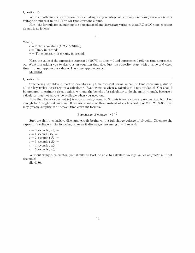
Calculating variables in reactive circuits using time-constant formulae can be time consuming, due toall the keystrokes necessary on a calculator. Even worse is when a calculator is not available! You shouldbe prepared to estimate circuit values without the benefit of a calculator to do the math, though, because acalculator may not always be available when you need one.
Note that Euler’s constant (e) is approximately equal to 3. This is not a close approximation, but closeenough for ”rough” estimations. If we use a value of three instead of e’s true value of 2.718281828· · ·, wemay greatly simplify the ”decay” time constant formula:
Percentage of change ≈ 3−t
τ
Suppose that a capacitive discharge circuit begins with a full-charge voltage of 10 volts. Calculate thecapacitor’s voltage at the following times as it discharges, assuming τ = 1 second:
t = 0 seconds ; EC =t = 1 second ; EC =t = 2 seconds ; EC =t = 3 seconds ; EC =t = 4 seconds ; EC =t = 5 seconds ; EC =
Without using a calculator, you should at least be able to calculate voltage values as fractions if notdecimals!
file 01804
10

Question 15
Calculating variables in reactive circuits using time-constant formulae can be time consuming, due toall the keystrokes necessary on a calculator. Even worse is when a calculator is not available! You shouldbe prepared to estimate circuit values without the benefit of a calculator to do the math, though, because acalculator may not always be available when you need one.
Note that Euler’s constant (e) is approximately equal to 3. This is not a close approximation, but closeenough for ”rough” estimations. If we use a value of three instead of e’s true value of 2.718281828· · ·, wemay greatly simplify the ”increasing” time constant formula:
Percentage of change ≈ 1 − 3−t
τ
Suppose that a capacitive charging circuit begins fully discharged (0 volts), and charges to an ultimatevalue of 10 volts. Calculate the capacitor’s voltage at the following times as it discharges, assuming τ = 1second:
t = 0 seconds ; EC =t = 1 second ; EC =t = 2 seconds ; EC =t = 3 seconds ; EC =t = 4 seconds ; EC =t = 5 seconds ; EC =
Without using a calculator, you should at least be able to calculate voltage values as fractions if notdecimals!
file 01805
11

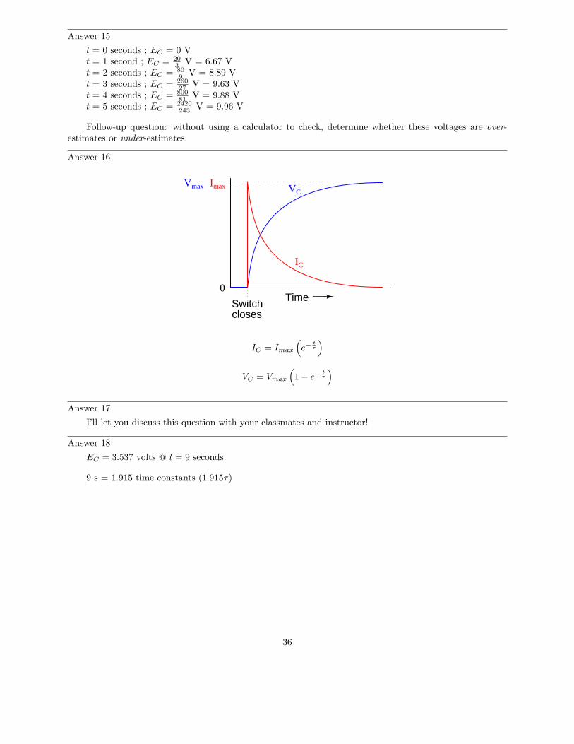
Question 16
Graph both the capacitor voltage (VC) and the capacitor current (IC) over time as the switch is closedin this circuit. Assume the capacitor begins in a complete uncharged state (0 volts):
Time
IC
Switchcloses
VC
Then, select and modify the appropriate form of equation (from below) to describe each plot:
e−t
τ 1 − e−t
τ
file 03550
Question 17
An unfortunate tendency that many new students have is to immediately plug numbers into equationswhen faced with a time-constant circuit problem, before carefully considering the circuit. Explain why thefollowing steps are very wise to follow before performing any mathematical calculations:
• Step 1: Identify and list all the known (”given”) quantities.• Step 2: Draw a schematic of the circuit, if none is given to you.• Step 3: Label components in the schematic with all known quantities.• Step 4: Sketch a rough plot of how you expect the variable(s) in the circuit to change over time.• Step 5: Label starting and final values for these graphed variables, wherever possible.
file 03553
Question 18
Calculate the voltage across a 470 µF capacitor after discharging through a 10 kΩ resistor for 9 seconds,if the capacitor’s original voltage (at t = 0) was 24 volts.
Also, express this amount of time (9 seconds) in terms of how many time constants have elapsed.file 00452
12

Question 19
The following circuit allows a capacitor to be rapidly charged and slowly discharged:
40 V
Charge Discharge
500µ
2k0
Suppose that the switch was left in the ”charge” position for some substantial amount of time. Then,someone moves the switch to the ”discharge” position to let the capacitor discharge. Calculate the amountof capacitor voltage and capacitor current at exactly 3 seconds after moving the switch to the ”discharge”position.
VC = @ t = 3 seconds
IC = @ t = 3 seconds
Also, show the direction of discharge current in this circuit.file 03552
Question 20
The following circuit allows a capacitor to be rapidly discharged and slowly charged:
Charge Discharge
15 V 2µ7
8k1
Suppose that the switch was left in the ”discharge” position for some substantial amount of time. Then,someone moves the switch to the ”charge” position to let the capacitor charge. Calculate the amount ofcapacitor voltage and capacitor current at exactly 45 milliseconds after moving the switch to the ”charge”position.
VC = @ t = 45 ms
IC = @ t = 45 msfile 03557
13

Question 21
Calculate the current through a 250 mH inductor after ”charging” through a series-connected resistorwith 100 Ω of resistance for 6 milliseconds, powered by a 12 volt battery. Assume that the inductor is perfect,with no internal resistance.
Also, express this amount of time (6 milliseconds) in terms of how many time constants have elapsed.file 00453
Question 22
Plot the capacitor voltage and the capacitor current over time after the switch closes in this circuit, forat least 4 time constants’ worth of time:
+V
-
A
10 µF
33 kΩ
18 V
EC
IC
Time
Be sure to label the axes of your graph!file 00456
14

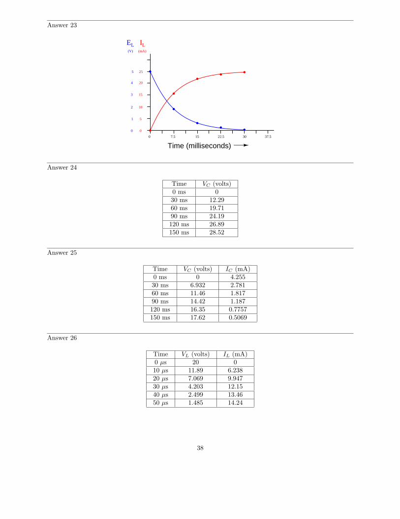
Question 23
Plot the inductor voltage and the inductor current over time after the switch closes in this circuit, forat least 4 time constants’ worth of time:
+V
-
A
Time
1.5 H
200 Ω
5 V
EL
IL
Be sure to label the axes of your graph!file 01806
Question 24
Determine the capacitor voltage at the specified times (time t = 0 milliseconds being the exact momentthe switch contacts close). Assume the capacitor begins in a fully discharged state:
Switch
31 V
R = 27 kΩ
C = 2.2 µF
Time VC (volts)0 ms30 ms60 ms90 ms120 ms150 ms
file 03555
15

Question 25
Determine the capacitor voltage and capacitor current at the specified times (time t = 0 millisecondsbeing the exact moment the switch contacts close). Assume the capacitor begins in a fully discharged state:
Switch
20 V C = 15 µF
R = 4.7 kΩ
Time VC (volts) IC (mA)0 ms30 ms60 ms90 ms120 ms150 ms
file 03556
Question 26
Determine the inductor voltage and inductor current at the specified times (time t = 0 millisecondsbeing the exact moment the switch contacts close):
Switch
20 V
R = 1.3 kΩ
L = 25 mH
Time VL (volts) IL (mA)0 µs10 µs20 µs30 µs40 µs50 µs
file 03589
16

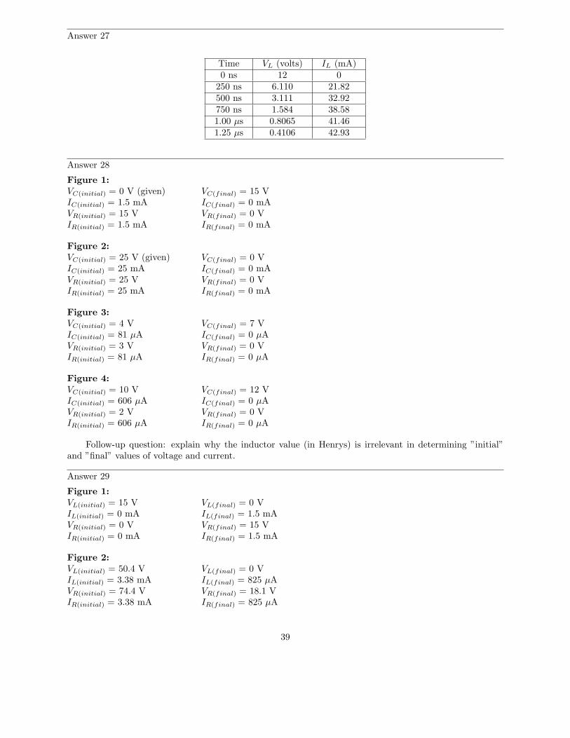
Question 27
Determine the inductor voltage and inductor current at the specified times (time t = 0 millisecondsbeing the exact moment the switch contacts close):
Switch
L = 100 µH
R = 270 Ω
12 V
Time VL (volts) IL (mA)0 ns
250 ns500 ns750 ns1.00 µs1.25 µs
file 03590
17
Question 28
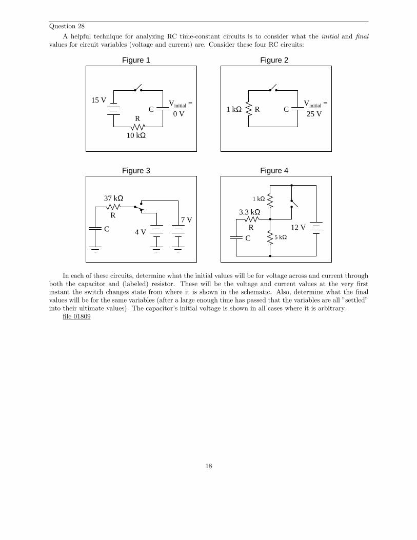
A helpful technique for analyzing RC time-constant circuits is to consider what the initial and final
values for circuit variables (voltage and current) are. Consider these four RC circuits:
Figure 1 Figure 2
15 V
10 kΩ
Vinitial =
0 V
Vinitial =1 kΩ
25 V
Figure 4Figure 3
3.3 kΩ
5 kΩ
1 kΩ
12 V4 V
7 V
37 kΩ
C C
CC
RR
R
R
In each of these circuits, determine what the initial values will be for voltage across and current throughboth the capacitor and (labeled) resistor. These will be the voltage and current values at the very firstinstant the switch changes state from where it is shown in the schematic. Also, determine what the finalvalues will be for the same variables (after a large enough time has passed that the variables are all ”settled”into their ultimate values). The capacitor’s initial voltage is shown in all cases where it is arbitrary.
file 01809
18

Question 29
A helpful technique for analyzing LR time-constant circuits is to consider what the initial and final
values for circuit variables (voltage and current) are. Consider these four LR circuits:
Figure 1 Figure 2
15 V
10 kΩ
Figure 4Figure 3
37 kΩ
R
R
L
R
L24 V7.1 kΩ
10 mAL
22 kΩ
R
L 3 V
9 V
4.7 kΩ
In each of these circuits, determine what the initial values will be for voltage across and current throughboth the inductor and (labeled) resistor. These will be the voltage and current values at the very first instantthe switch changes state from where it is shown in the schematic. Also, determine what the final values willbe for the same variables (after a large enough time has passed that the variables are all ”settled” into theirultimate values).
Assume all inductors are ideal, possessing no coil resistance (Rcoil = 0 Ω).file 01810
19

Question 30
A formula I like to use in calculating voltage and current values in either RC or LR circuits has twoforms, one for voltage and one for current:
V (t) = (Vf − V0)
(
1 −1
et
τ
)
+ V0 (for calculating voltage)
I(t) = (If − I0)
(
1 −1
et
τ
)
+ I0 (for calculating current)
The ”0” subscript represents the condition at time = 0 (V0 or I0, respectively), representing the ”initial”value of that variable. The ”f” subscript represents the ”final” or ”ultimate” value that the voltage or currentwould achieve if allowed to progress indefinitely. Obviously, one must know how to determine the ”initial”and ”final” values in order to use either of these formulae, but once you do you will be able to calculate any
voltage and any current at any time in either an RC or LR circuit.What is not so obvious to students is how each formula works. Specifically, what does each portion of it
represent, in practical terms? This is your task: to describe what each term of the equation means in yourown words. I will list the ”voltage” formula terms individually for you to define:
V (t) =
(Vf − V0) =
(
1 −1
et
τ
)
=
file 01813
Question 31
Determine the voltage across the capacitor three seconds after the switch is moved from the upperposition to the lower position, assuming it had been left in the upper position for a long time:
22 µF
75 kΩ
3 V 9 V
file 00457
20

Question 32
Assume that the switch in this circuit is toggled (switched positions) once every 5 seconds, beginningin the ”up” (charge) position at time t = 0, and that the capacitor begins in a fully discharged state at thattime. Determine the capacitor voltage at each switch toggle:
Switch
10 V 470 µF
10 kΩ
Time Switch motion VC (volts)0 s discharge → charge 0 volts5 s charge → discharge10 s discharge → charge15 s charge → discharge20 s discharge → charge25 s charge → discharge
file 03668
Question 33
This passive integrator circuit is powered by a square-wave voltage source (oscillating between 0 voltsand 5 volts at a frequency of 2 kHz). Determine the output voltage (vout) of the integrator at each instantin time where the square wave transitions (goes from 0 to 5 volts, or from 5 to 0 volts), assuming that thecapacitor begins in a fully discharged state at the first transition (from 0 volts to 5 volts):
10 kΩ
0 V
+5 V
2 kHz
0.022 µF
Passive integrator
vout
Transition vout
#1 (0 → 5 volts) 0 volts#2 (5 → 0 volts)#3 (0 → 5 volts)#4 (5 → 0 volts)#5 (0 → 5 volts)#6 (5 → 0 volts)#7 (0 → 5 volts)#8 (5 → 0 volts)
file 03669
21

Question 34
Calculate the voltage across the switch contacts the exact moment they open, and 15 milliseconds afterthey have been opened:
9 V
1k5
10
330
file 00458
Question 35
Calculate the voltage across a 2.5 H inductor after ”charging” through a series-connected resistor with50 Ω of resistance for 75 milliseconds, powered by a 6 volt battery. Assume that the inductor has an internalresistance of 14 Ω.
Also, express this amount of time (75 milliseconds) in terms of how many time constants have elapsed.
Hint: it would be helpful in your analysis to draw a schematic diagram of this circuit showing theinductor’s inductance and 14 ohms of resistance as two separate (idealized) components. This is a verycommon analysis technique in electrical engineering: to regard the parasitic characteristics of a componentas a separate component in the same circuit.
file 00454
Question 36
The decay of a variable over time in an RC or LR circuit follows this mathematical expression:
e−t
τ
Where,e = Euler’s constant (≈ 2.718281828)t = Time, in secondsτ = Time constant of circuit, in seconds
For example, if we were to evaluate this expression and arrive at a value of 0.398, we would know thevariable in question has decayed from 100% to 39.8% over the period of time specified.
However, calculating the amount of time it takes for a decaying variable to reach a specified percentageis more difficult. We would have to manipulate the equation to solve for t, which is part of an exponent.
Show how the following equation could be algebraically manipulated to solve for t, where x is the numberbetween 0 and 1 (inclusive) representing the percentage of original value for the variable in question:
x = e−t
τ
Note: the ”trick” here is how to isolate the exponent −tτ
. You will have to use the natural logarithmfunction!
file 02001
22

Question 37
Design an experiment to calculate the size of a capacitor based on its response in a time-constant circuit.Include in your design an equation that gives the value of the capacitor in farads, based on data obtainedby running the experiment.
file 00455
Question 38
Calculate the amount of time it takes for a 33 µF capacitor to charge from 0 volts to 20 volts, if poweredby a 24 volt battery through a 10 kΩ resistor.
file 01814
Question 39
Calculate the amount of time it takes for a 10 µF capacitor to discharge from 18 volts to 7 volts if itsultimate (final) voltage when fully discharged will be 0 volts, and it is discharging through a 22 kΩ resistor.
file 02941
Question 40
A 470 µF capacitor begins in a charged state of 270 volts, and discharges through a 100 kΩ resistor.How long will it take before the capacitor’s voltage will fall to a relatively safe value (30 volts or less)?
file 04072
Question 41
Complete this table of values for inductor voltage and current. Consider time = 0 to be the precisemoment the switch closes:
250 mH
2.2 kΩ
1 kΩ16 V
Time (µs) VL (V) IL (mA)050100150200250300350400
file 01815
23

Question 42
Determine the amount of time needed after switch closure for the capacitor voltage (VC) to reach thespecified levels:
40 VDC C = 4.7 µF
R = 220 kΩSwitch
+−
VC Time0 volts10 volts20 volts30 volts40 volts
Trace the direction of electron flow in the circuit, and also mark all voltage polarities.file 02942
Question 43
Determine the amount of time needed after switch closure for the capacitor voltage (VC) to reach thespecified levels:
Switch
20 VDC
R = 47 kΩ
C = 2.2 µF
VC Time0 volts-5 volts-10 volts-15 volts-19 volts
Trace the direction of current in the circuit while the capacitor is charging, and be sure to denotewhether you are using electron or conventional flow notation.
Note: the voltages are specified as negative quantities because they are negative with respect to (positive)ground in this particular circuit.
file 03118
24

Question 44
Determine the amount of time needed for the capacitor voltage (VC) to fall to the specified levels afterthe switch is thrown to the ”discharge” position, assuming it had first been charged to full battery voltage:
Switch
12 V
R = 190 kΩ
C = 17 µF
VC Time10 volts8 volts6 volts4 volts2 volts
Trace the direction of electron flow in the circuit, and also mark all voltage polarities.file 02943
25
Question 45
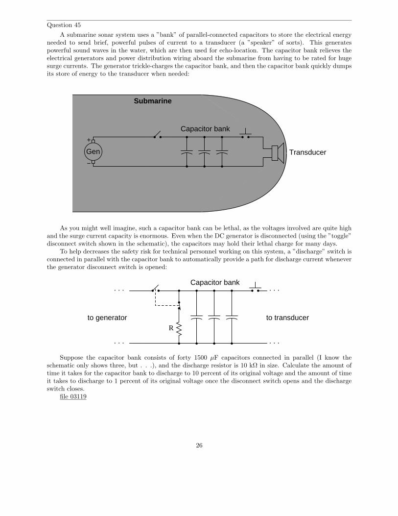
A submarine sonar system uses a ”bank” of parallel-connected capacitors to store the electrical energyneeded to send brief, powerful pulses of current to a transducer (a ”speaker” of sorts). This generatespowerful sound waves in the water, which are then used for echo-location. The capacitor bank relieves theelectrical generators and power distribution wiring aboard the submarine from having to be rated for hugesurge currents. The generator trickle-charges the capacitor bank, and then the capacitor bank quickly dumpsits store of energy to the transducer when needed:
Gen Transducer
Capacitor bank
Submarine
As you might well imagine, such a capacitor bank can be lethal, as the voltages involved are quite highand the surge current capacity is enormous. Even when the DC generator is disconnected (using the ”toggle”disconnect switch shown in the schematic), the capacitors may hold their lethal charge for many days.
To help decreases the safety risk for technical personnel working on this system, a ”discharge” switch isconnected in parallel with the capacitor bank to automatically provide a path for discharge current wheneverthe generator disconnect switch is opened:
Capacitor bank. . .
. . .
to transducer
. . .
. . .
to generatorR
Suppose the capacitor bank consists of forty 1500 µF capacitors connected in parallel (I know theschematic only shows three, but . . .), and the discharge resistor is 10 kΩ in size. Calculate the amount oftime it takes for the capacitor bank to discharge to 10 percent of its original voltage and the amount of timeit takes to discharge to 1 percent of its original voltage once the disconnect switch opens and the dischargeswitch closes.
file 03119
26
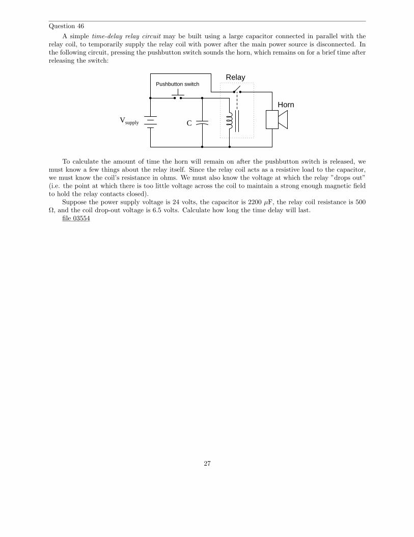
Question 46
A simple time-delay relay circuit may be built using a large capacitor connected in parallel with therelay coil, to temporarily supply the relay coil with power after the main power source is disconnected. Inthe following circuit, pressing the pushbutton switch sounds the horn, which remains on for a brief time afterreleasing the switch:
Vsupply
Pushbutton switchRelay
Horn
C
To calculate the amount of time the horn will remain on after the pushbutton switch is released, wemust know a few things about the relay itself. Since the relay coil acts as a resistive load to the capacitor,we must know the coil’s resistance in ohms. We must also know the voltage at which the relay ”drops out”(i.e. the point at which there is too little voltage across the coil to maintain a strong enough magnetic fieldto hold the relay contacts closed).
Suppose the power supply voltage is 24 volts, the capacitor is 2200 µF, the relay coil resistance is 500Ω, and the coil drop-out voltage is 6.5 volts. Calculate how long the time delay will last.
file 03554
27
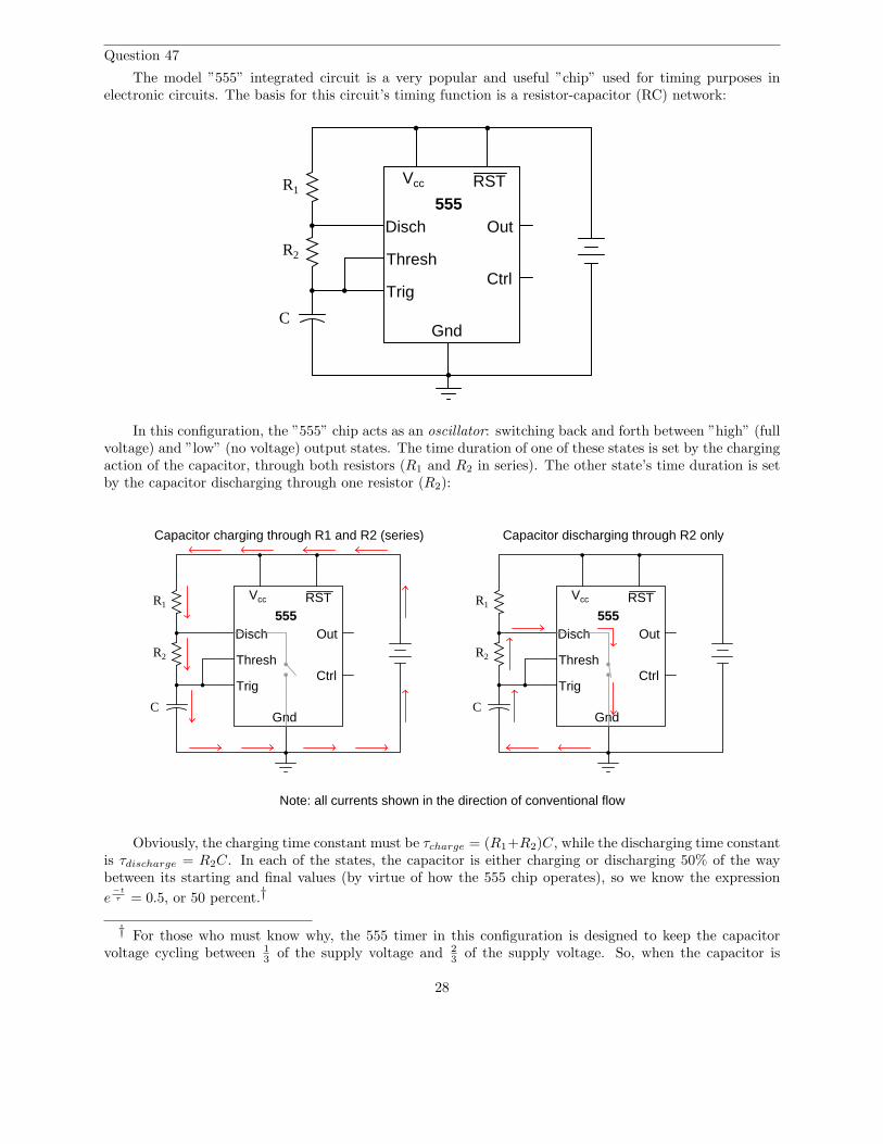
Question 47
The model ”555” integrated circuit is a very popular and useful ”chip” used for timing purposes inelectronic circuits. The basis for this circuit’s timing function is a resistor-capacitor (RC) network:
555Disch
Thresh
Trig
Gnd
Vcc RST
Out
Ctrl
R1
R2
C
In this configuration, the ”555” chip acts as an oscillator: switching back and forth between ”high” (fullvoltage) and ”low” (no voltage) output states. The time duration of one of these states is set by the chargingaction of the capacitor, through both resistors (R1 and R2 in series). The other state’s time duration is setby the capacitor discharging through one resistor (R2):
555Disch
Thresh
Trig
Gnd
Vcc RST
Out
Ctrl
R1
R2
C
Capacitor charging through R1 and R2 (series)
555Disch
Thresh
Trig
Gnd
Vcc RST
Out
Ctrl
R1
R2
C
Capacitor discharging through R2 only
Note: all currents shown in the direction of conventional flow
Obviously, the charging time constant must be τcharge = (R1+R2)C, while the discharging time constantis τdischarge = R2C. In each of the states, the capacitor is either charging or discharging 50% of the waybetween its starting and final values (by virtue of how the 555 chip operates), so we know the expression
e−t
τ = 0.5, or 50 percent.†
† For those who must know why, the 555 timer in this configuration is designed to keep the capacitorvoltage cycling between 1
3 of the supply voltage and 23 of the supply voltage. So, when the capacitor is
28

Develop two equations for predicting the ”charge” time and ”discharge” time of this 555 timer circuit,so that anyone designing such a circuit for specific time delays will know what resistor and capacitor valuesto use.
file 01807
Question 48
Calculate the rate of change of voltage (dvdt
) for the capacitor at the exact instant in time where theswitch moves to the ”charge” position. Assume that prior to this motion the switch had been left in the”discharge” position for some time:
Charge Discharge
22 V
1k5
3µ3
file 03558
Question 49
Calculate the rate of change of current ( didt
) for the inductor at the exact instant in time where theswitch moves to the ”charge” position.
Charge Discharge
50m
470
14 V
file 03559
charging from 13VCC to its (final) value of full supply voltage (VCC), having this charge cycle interrupted
at 23VCC by the 555 chip constitutes charging to the half-way point, since 2
3 of half-way between 13 and 1.
When discharging, the capacitor starts at 23VCC and is interrupted at 1
3VCC , which again constitutes 50%of the way from where it started to where it was (ultimately) headed.
29

Question 50∫
f(x) dx Calculus alert!
Differential equations may be used to model the charging behavior of an L/R circuit. Take, for instance,this simple L/R circuit:
2 H
50 Ω
40 VDC
We may develop a loop equation based on Kirchhoff’s Voltage Law, knowing that the voltage of thepower source is constant (40 volts), and that the voltage drops across the inductor and resistor are VL = LdI
dt
and VR = IR, respectively:
40 − IR − LdI
dt= 0
Show that the specific solution to this differential equation, assuming an initial condition of I = 0 att = 0, is as follows:
I = 0.8(1 − e−25t)
file 01511
30
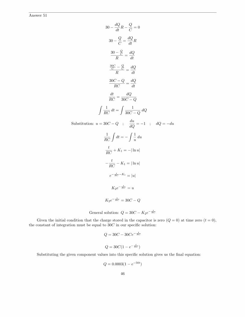
Question 51∫
f(x) dx Calculus alert!
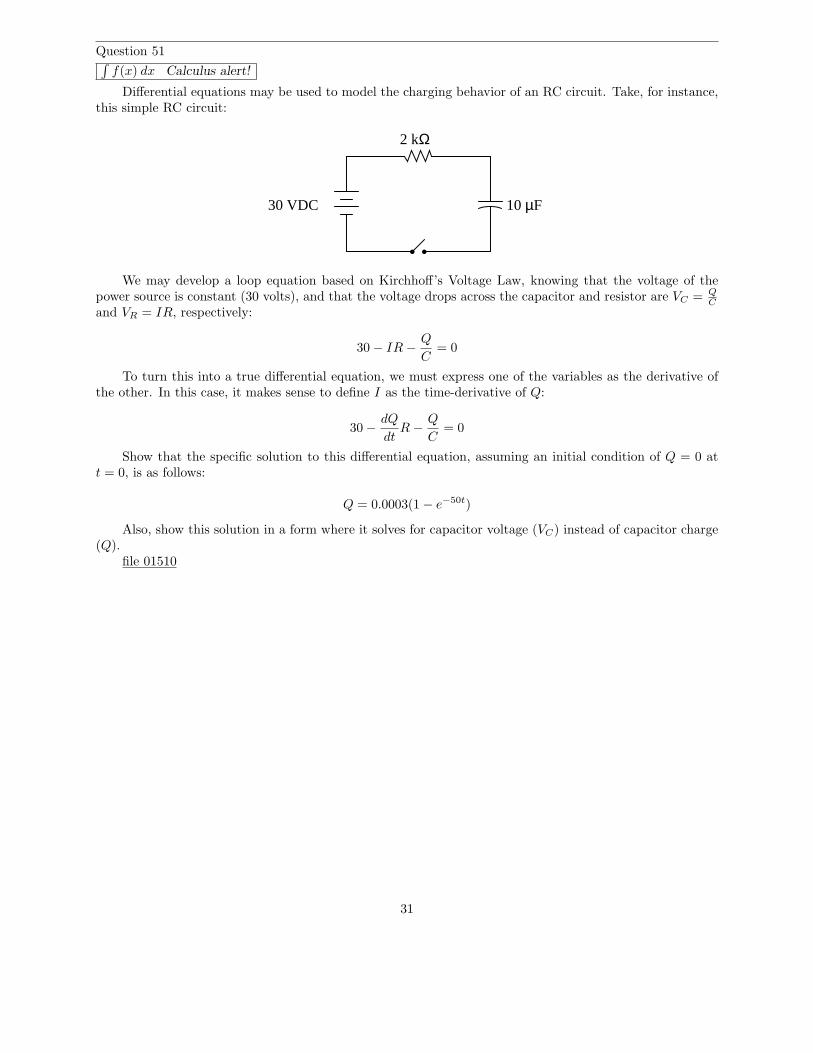
Differential equations may be used to model the charging behavior of an RC circuit. Take, for instance,this simple RC circuit:
2 kΩ
10 µF30 VDC
We may develop a loop equation based on Kirchhoff’s Voltage Law, knowing that the voltage of thepower source is constant (30 volts), and that the voltage drops across the capacitor and resistor are VC = Q
C
and VR = IR, respectively:
30 − IR −Q
C= 0
To turn this into a true differential equation, we must express one of the variables as the derivative ofthe other. In this case, it makes sense to define I as the time-derivative of Q:
30 −dQ
dtR −
Q
C= 0
Show that the specific solution to this differential equation, assuming an initial condition of Q = 0 att = 0, is as follows:
Q = 0.0003(1 − e−50t)
Also, show this solution in a form where it solves for capacitor voltage (VC) instead of capacitor charge(Q).
file 01510
31
Question 52
Don’t just sit there! Build something!!
Learning to mathematically analyze circuits requires much study and practice. Typically, studentspractice by working through lots of sample problems and checking their answers against those provided bythe textbook or the instructor. While this is good, there is a much better way.
You will learn much more by actually building and analyzing real circuits, letting your test equipmentprovide the ”answers” instead of a book or another person. For successful circuit-building exercises, followthese steps:
1. Carefully measure and record all component values prior to circuit construction.2. Draw the schematic diagram for the circuit to be analyzed.3. Carefully build this circuit on a breadboard or other convenient medium.4. Check the accuracy of the circuit’s construction, following each wire to each connection point, and
verifying these elements one-by-one on the diagram.5. Mathematically analyze the circuit, solving for all values of voltage, current, etc.6. Carefully measure those quantities, to verify the accuracy of your analysis.7. If there are any substantial errors (greater than a few percent), carefully check your circuit’s construction
against the diagram, then carefully re-calculate the values and re-measure.
Avoid very high and very low resistor values, to avoid measurement errors caused by meter ”loading”.I recommend resistors between 1 kΩ and 100 kΩ, unless, of course, the purpose of the circuit is to illustratethe effects of meter loading!
One way you can save time and reduce the possibility of error is to begin with a very simple circuit andincrementally add components to increase its complexity after each analysis, rather than building a wholenew circuit for each practice problem. Another time-saving technique is to re-use the same components in avariety of different circuit configurations. This way, you won’t have to measure any component’s value morethan once.
file 00405
32
Answers
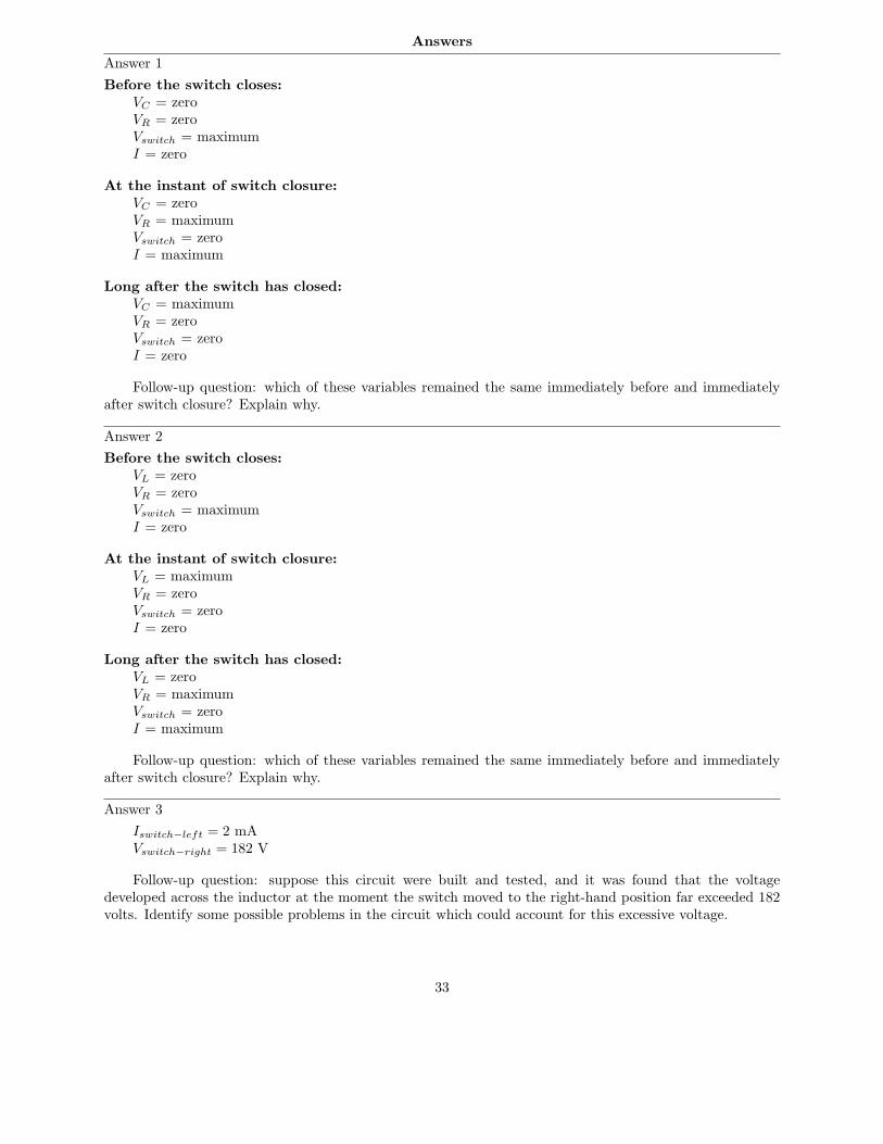
Answer 1
Before the switch closes:
VC = zeroVR = zeroVswitch = maximumI = zero
At the instant of switch closure:
VC = zeroVR = maximumVswitch = zeroI = maximum
Long after the switch has closed:
VC = maximumVR = zeroVswitch = zeroI = zero
Follow-up question: which of these variables remained the same immediately before and immediatelyafter switch closure? Explain why.
Answer 2
Before the switch closes:
VL = zeroVR = zeroVswitch = maximumI = zero
At the instant of switch closure:
VL = maximumVR = zeroVswitch = zeroI = zero
Long after the switch has closed:
VL = zeroVR = maximumVswitch = zeroI = maximum
Follow-up question: which of these variables remained the same immediately before and immediatelyafter switch closure? Explain why.
Answer 3
Iswitch−left = 2 mAVswitch−right = 182 V
Follow-up question: suppose this circuit were built and tested, and it was found that the voltagedeveloped across the inductor at the moment the switch moved to the right-hand position far exceeded 182volts. Identify some possible problems in the circuit which could account for this excessive voltage.
33

Answer 4
• 1 time constant (τ) after connecting the resistor: VC = 36.79 volts• 2 time constants (2τ) after connecting the resistor: VC = 13.53 volts• 3 time constants (3τ) after connecting the resistor: VC = 4.979 volts• 4 time constants (4τ) after connecting the resistor: VC = 1.832 volts• 5 time constants (5τ) after connecting the resistor: VC = 0.6738 volts
Follow-up question: write an equation solving for these voltages at the specified times.
Answer 5
• RC circuit; R = 10 kΩ, C = 220 µF ; 7.5 sec = 3.41 τ
• RC circuit; R = 33 kΩ, C = 470 µF ; 7.5 sec = 0.484 τ
• RC circuit; R = 1.5 kΩ, C = 100 µF ; 7.5 sec = 50.0 τ
• RC circuit; R = 790 Ω, C = 9240 nF ; 7.5 sec = 1027 τ
• RC circuit; R = 100 kΩ, C = 33 pF ; 7.5 sec = 2,272,727 τ
• LR circuit; R = 100 Ω, L = 50 mH ; 7.5 sec = 15,000 τ
• LR circuit; R = 45 Ω, L = 2.2 H ; 7.5 sec = 153.4 τ
• LR circuit; R = 1 kΩ, L = 725 mH ; 7.5 sec = 10,345 τ
• LR circuit; R = 4.7 kΩ, L = 325 mH ; 7.5 sec = 108,462 τ
• LR circuit; R = 6.2 Ω, L = 25 H ; 7.5 sec = 1.86 τ
Answer 6
e−x =1
ex
Answer 7
t = 1 second ; e−t
τ = 36.788%t = 2 seconds ; e−
t
τ = 13.534%t = 3 seconds ; e−
t
τ = 4.979%t = 4 seconds ; e−
t
τ = 1.832%t = 5 seconds ; e−
t
τ = 0.6738%t = 6 seconds ; e−
t
τ = 0.2479%t = 7 seconds ; e−
t
τ = 0.09119%t = 8 seconds ; e−
t
τ = 0.03355%t = 9 seconds ; e−
t
τ = 0.01234%t = 10 seconds ; e−
t
τ = 0.004540%
34

Answer 8
t = 1 second ; e−t
τ = 60.65% ; increasing variable = 39.35%t = 2 seconds ; e−
t
τ = 36.79% ; increasing variable = 63.21%t = 3 seconds ; e−
t
τ = 22.31% ; increasing variable = 77.69%t = 4 seconds ; e−
t
τ = 13.53% ; increasing variable = 86.47%t = 5 seconds ; e−
t
τ = 8.208% ; increasing variable = 91.79%t = 6 seconds ; e−
t
τ = 4.979% ; increasing variable = 95.02%t = 7 seconds ; e−
t
τ = 3.020% ; increasing variable = 96.98%t = 8 seconds ; e−
t
τ = 1.832% ; increasing variable = 98.17%t = 9 seconds ; e−
t
τ = 1.111% ; increasing variable = 98.89%t = 10 seconds ; e−
t
τ = 0.6738% ; increasing variable = 99.33%
Answer 9
This equation models the percentage of pizza remaining on the table at time t, not how much has alreadybeen eaten.
Answer 10
This equation models the percentage of pizza eaten at time t, not how much remains on the table.
Answer 11
Whether the variable in question is increasing or decreasing over time, the expression e−t
τ describes thepercentage that a variable has left to change before it reaches its final value.
Follow-up question: what could you add to or modify about the expression to make it describe thepercentage that a variable has already changed from its initial value? In other words, alter the expressionso that it is equal to 0% at t = 0 and approaches 100% as t grows larger (t → ∞).
Answer 12
Here is a hint: set x to zero and evaluate each equation.
Answer 13
(1 − e−t
τ )(100%)
Answer 14
t = 0 seconds ; EC = 10 V
t = 1 second ; EC = 103 V = 3.33 V
t = 2 seconds ; EC = 109 V = 1.11 V
t = 3 seconds ; EC = 1027 V = 0.370 V
t = 4 seconds ; EC = 1081 V = 0.123 V
t = 5 seconds ; EC = 10243 V = 0.0412 V
Follow-up question: without using a calculator to check, determine whether these voltages are over-estimates or under-estimates.
35
Answer 15
t = 0 seconds ; EC = 0 Vt = 1 second ; EC = 20
3 V = 6.67 Vt = 2 seconds ; EC = 80
9 V = 8.89 Vt = 3 seconds ; EC = 260
27 V = 9.63 Vt = 4 seconds ; EC = 800
81 V = 9.88 Vt = 5 seconds ; EC = 2420
243 V = 9.96 V
Follow-up question: without using a calculator to check, determine whether these voltages are over-estimates or under-estimates.
Answer 16
TimeSwitchcloses
IC
VCVmax Imax
0
IC = Imax
(
e−t
τ
)
VC = Vmax
(
1 − e−t
τ
)
Answer 17
I’ll let you discuss this question with your classmates and instructor!
Answer 18
EC = 3.537 volts @ t = 9 seconds.
9 s = 1.915 time constants (1.915τ)
36

Answer 19
VC = 1.9915 volts @ t = 3 seconds
IC = 995.74 µA @ t = 3 seconds
40 V
Charge Discharge
Arrows pointing in the directionof conventional flow
500µ
2k0
Answer 20
VC = -13.08 volts @ t = 45 ms
IC = 236.6 µA @ t = 45 ms
Follow-up question: show the directions of charge and discharge current in this circuit.
Answer 21
IL = 109.11 mA @ t = 6 milliseconds
6 ms = 2.4 time constants (2.4τ)
Answer 22
EC IC
0 0.25 0.5 0.75 1.0 1.25 1.5 1.75 2.0 2.25 2.5
Time (seconds)
3
6
9
12
15
18
0
600
500
400
300
200
100
0
(µA)(V)
37
Answer 23
0
0 0
(V)
EL IL(mA)
1
2
3
4
5 25
20
15
10
5
Time (milliseconds)7.5 15 22.5 30 37.5
Answer 24
Time VC (volts)0 ms 030 ms 12.2960 ms 19.7190 ms 24.19120 ms 26.89150 ms 28.52
Answer 25
Time VC (volts) IC (mA)0 ms 0 4.25530 ms 6.932 2.78160 ms 11.46 1.81790 ms 14.42 1.187120 ms 16.35 0.7757150 ms 17.62 0.5069
Answer 26
Time VL (volts) IL (mA)0 µs 20 010 µs 11.89 6.23820 µs 7.069 9.94730 µs 4.203 12.1540 µs 2.499 13.4650 µs 1.485 14.24
38
Answer 27
Time VL (volts) IL (mA)0 ns 12 0
250 ns 6.110 21.82500 ns 3.111 32.92750 ns 1.584 38.581.00 µs 0.8065 41.461.25 µs 0.4106 42.93
Answer 28
Figure 1:
VC(initial) = 0 V (given) VC(final) = 15 VIC(initial) = 1.5 mA IC(final) = 0 mAVR(initial) = 15 V VR(final) = 0 VIR(initial) = 1.5 mA IR(final) = 0 mA
Figure 2:
VC(initial) = 25 V (given) VC(final) = 0 VIC(initial) = 25 mA IC(final) = 0 mAVR(initial) = 25 V VR(final) = 0 VIR(initial) = 25 mA IR(final) = 0 mA
Figure 3:
VC(initial) = 4 V VC(final) = 7 VIC(initial) = 81 µA IC(final) = 0 µAVR(initial) = 3 V VR(final) = 0 VIR(initial) = 81 µA IR(final) = 0 µA
Figure 4:
VC(initial) = 10 V VC(final) = 12 VIC(initial) = 606 µA IC(final) = 0 µAVR(initial) = 2 V VR(final) = 0 VIR(initial) = 606 µA IR(final) = 0 µA
Follow-up question: explain why the inductor value (in Henrys) is irrelevant in determining ”initial”and ”final” values of voltage and current.
Answer 29
Figure 1:
VL(initial) = 15 V VL(final) = 0 VIL(initial) = 0 mA IL(final) = 1.5 mAVR(initial) = 0 V VR(final) = 15 VIR(initial) = 0 mA IR(final) = 1.5 mA
Figure 2:
VL(initial) = 50.4 V VL(final) = 0 VIL(initial) = 3.38 mA IL(final) = 825 µAVR(initial) = 74.4 V VR(final) = 18.1 VIR(initial) = 3.38 mA IR(final) = 825 µA
39

Figure 3:
VL(initial) = 370 V VL(final) = 0 VIL(initial) = 10 mA IL(final) = 0 mAVR(initial) = 370 V VR(final) = 0 VIR(initial) = 10 mA IR(final) = 0 mA
Figure 4:
VL(initial) = 6 V VL(final) = 0 VIL(initial) = 638 µA IL(final) = 1.91 mAVR(initial) = 3 V VR(final) = 9 VIR(initial) = 638 µA IR(final) = 1.91 mA
Follow-up question: explain why the inductor value (in Henrys) is irrelevant in determining ”initial”and ”final” values of voltage and current.
Answer 30
The term V (t) uses symbolism common to calculus and pre-calculus, pronounced ”V of t,” meaning”voltage at time t”. It means that the variable V changes as a function of time t.
(Vf − V0) represents the amount of change that the voltage would go through, from the start of thecharge/discharge cycle until eternity. Note that the sign (positive or negative) of this term is very important!
(
1 − 1
et
τ
)
is the fractional value (between 0 and 1, inclusive) expressing how far the voltage has changed
from its initial value to its final value.
Follow-up question: why is it important to add the final V0 term to the expression? Why not leave the
formula at V (t) = (Vf − V0)(
1 − 1
et
τ
)
?
Answer 31
EC = 3.974 V @ 3 seconds
Follow-up question: identify at least one failure in this circuit which would cause the capacitor to remaincompletely discharged no matter what position the switch was in.
Answer 32
Time Switch motion VC (volts)0 s discharge → charge 0 volts5 s charge → discharge 6.549 volts10 s discharge → charge 2.260 volts15 s charge → discharge 7.329 volts20 s discharge → charge 2.529 volts25 s charge → discharge 7.422 volts
40

Answer 33
Transition vout
#1 (0 → 5 volts) 0 volts#2 (5 → 0 volts) 3.395 volts#3 (0 → 5 volts) 1.090 volts#4 (5 → 0 volts) 3.745 volts#5 (0 → 5 volts) 1.202 volts#6 (5 → 0 volts) 3.781 volts#7 (0 → 5 volts) 1.214 volts#8 (5 → 0 volts) 3.785 volts
Challenge question: what are the final (ultimate) values for the integrator output’s sawtooth-wave peakvoltages?
Answer 34
Eswitch = 40.91 V @ t = 0 secondsEswitch = 9.531 V @ t = 15 milliseconds
Follow-up question: predict all voltage drops in this circuit in the event that the inductor fails open(broken wire inside).
Answer 35
Equivalent schematic:
6 V2.5 H
50 Ω
14 ΩInductorwith coil
resistance
EL = 2.00 V @ t = 75 milliseconds75 ms = 1.92 time constants (1.92τ)
41

Answer 36
Showing all the necessary steps:
x = e−t
τ
lnx = ln(
e−t
τ
)
lnx = −t
τ
t = −τ lnx
Answer 37
I recommend the following circuit for testing the capacitor:
+V
-
The equation is yours to develop – I will not reveal it here. However, this does not mean there is noway to verify the accuracy of your equation, once you write it. Explain how it would be possible to provethe accuracy of your algebra, once you have written the equation.
Answer 38
0.591 seconds
Answer 39
0.208 seconds
Answer 40
It will take 103.3 seconds for the voltage to fall to 30 volts.
Answer 41
Time (µs) VL (V) IL (mA)0 5.00 5.0050 3.22 5.81100 2.07 6.33150 1.34 6.67200 0.860 6.88250 0.554 7.02300 0.357 7.11350 0.230 7.17400 0.148 7.21
42

Answer 42
40 VDC C = 4.7 µF
R = 220 kΩSwitch
(electron flow)
+−
VC Time0 volts 0 ms10 volts 297.5 ms20 volts 716.7 ms30 volts 1.433 s40 volts > 5 s
Answer 43
VC Time0 volts 0 ms-5 volts 29.75 ms-10 volts 71.67 ms-15 volts 143.3 ms-19 volts 309.8 ms
While the capacitor is charging, electron flow moves clockwise and conventional flow moves counter-clockwise.
Answer 44
Switch
(electron flow)12 V
R = 190 kΩ
C = 17 µF
VC Time10 volts 588.9 ms8 volts 1.31 s6 volts 2.24 s4 volts 3.55 s2 volts 5.79 s
43

Answer 45
Time to reach 10% ≈ 23 minutes
Time to reach 1% ≈ 46 minutes
Follow-up question: without using the time constant formula again, calculate how long it will take todischarge to 0.1% of its original voltage. How about 0.01%?
Answer 46
tdelay = 1.437 seconds
Answer 47
tcharge = − ln 0.5(R1 + R2)C
tdischarge = − ln 0.5R2C
Answer 48dvdt
= 4.44 kV/s or 4.44 V/ms
Answer 49didt
= 280 A/s or 0.28 A/ms
Follow-up question: does the resistor value have any effect on this initial didt
? Explain why or why not.
44

Answer 50
40 − IR − LdI
dt= 0
40 − IR = LdI
dt
40 − IR
L=
dI
dt
dt
L=
dI
40 − IR
∫
1
Ldt =
∫
1
40 − IRdI
Substitution: u = 40 − IR ;du
dI= −R ; dI = −
1
Rdu
1
L
∫
dt = −1
R
∫
1
udu
t
L+ K1 = −
1
R| ln u|
−tR
L+ K2 = | ln u|
e−tR
L+K2 = |u|
K3e−
tR
L = u
K3e−
tR
L = 40 − IR
IR = 40 − K3e−
tR
L
I =40
R− K4e
−
tR
L
Given the initial condition of zero current (I = 0) at time zero (t = 0), the constant of integration mustbe equal to 40
Rin our specific solution:
I =40
R−
40
Re−
tR
L
I =40
R(1 − e−
tR
L )
Substituting the given component values into this specific solution gives us the final equation:
I = 0.8(1 − e−25t)
45
Answer 51
30 −dQ
dtR −
Q
C= 0
30 −Q
C=
dQ
dtR
30 − QC
R=
dQ
dt
30CC
− QC
R=
dQ
dt
30C − Q
RC=
dQ
dt
dt
RC=
dQ
30C − Q
∫
1
RCdt =
∫
1
30C − QdQ
Substitution: u = 30C − Q ;du
dQ= −1 ; dQ = −du
1
RC
∫
dt = −
∫
1
udu
t
RC+ K1 = −| ln u|
−t
RC− K1 = | ln u|
e−t
RC−K1 = |u|
K2e−
t
RC = u
K2e−
t
RC = 30C − Q
General solution: Q = 30C − K2e−
t
RC
Given the initial condition that the charge stored in the capacitor is zero (Q = 0) at time zero (t = 0),the constant of integration must be equal to 30C in our specific solution:
Q = 30C − 30Ce−t
RC
Q = 30C(1 − e−t
RC )
Substituting the given component values into this specific solution gives us the final equation:
Q = 0.0003(1 − e−50t)
46

Showing a final equation in terms of capacitor voltage instead of capacitor charge:
Q
C=
30C
C(1 − e−
t
RC )
VC = 30(1 − e−50t)
Answer 52
Let the electrons themselves give you the answers to your own ”practice problems”!
47
Notes
Notes 1
The purpose of this question is to preview the concept of ”initial” and ”final” values in RC circuits,before they learn to use the ”universal time constant formula.”
Notes 2
The purpose of this question is to preview the concept of ”initial” and ”final” values in RC circuits,before they learn to use the ”universal time constant formula.”
Notes 3
The main purpose of this question is to get students thinking in terms of ”initial” and ”final” valuesfor LR circuits, and how one might calculate them. It is largely a conceptual question, with just a bit ofcalculation necessary.
One practical application of this circuit is for ”stepping up” DC voltage. The circuit topology shown inthe question is that of an inverting converter circuit. This form of DC-DC converter circuit has the abilityto step voltage up or down, depending on the duty cycle of the switch’s oscillation.
Notes 4
Although students should be able to look up approximate answers to this question from almost anybeginning electronics textbook, the point here is to get them to relate the question to an actual formula sothey may calculate this on their own.
Notes 5
An interesting thing to note here is the span of time constant values available from commoncapacitor/inductor/resistor sizes. As students should notice, the capacitor-resistor combinations (all verypractical values, I might add) create both longer and shorter time constant values than the inductor-resistorcombinations, and that is even including the 25 Henry - 6.2 Ohm combination, which would be difficult(read: expensive) to achieve in real life.
Notes 6
I am usually not a fan of discussing calculator keystroke sequences to college-level students, but I haveresorted to this at the college where I teach because so many of my students have no idea of how to evaluateexponential expressions! Of course, the actual keystrokes one must push to evaluate this expression dependon the brand of calculator used.
Notes 7
The purpose of this question is for students to learn the significance of the expression e−t
τ by ”playing”with the numbers. The negative exponent may confuse some students, so be sure to discuss its significancewith all students, so that all understand what it means.
Another concept for students to grasp in this question is that of an asymptotic function: a function thatapproaches a final value in incrementally smaller intervals.
48
Notes 8
Do not simply tell your students how to calculate the values of the increasing variable. Based on theirqualitative knowledge of time-constant circuit curves and their ability to evaluate the downward (decay)expression, they should be able to figure out how to calculate the increasing variable’s value over time aswell.
Some students will insist that you give them an equation to do this. They want to be told what todo, rather than solve the problem on their own based on an observation of pattern. It is very importantthat students of any science learn to recognize patterns in data, and that they learn to fit that data into amathematical equation. If nothing else, these figures given in the answer for both decreasing and increasingvariables should be plain enough.
Notes 9
While some may wonder what this question has to do with electronics, it is an exercise in qualitativeanalysis. This skill is very important for students to master if they are to be able to distinguish between theequations e−
t
τ and 1 − e−t
τ , both used in time-constant circuit analysis.The actual procedure for determining the nature of the equation is simple: consider what happens as t
begins at 0 and as it increases to some arbitrary positive value. Some students may rely on their calculators,performing actual calculations to see whether the percentage increases or decreases with increasing t.Encourage them to analyze the equation qualitatively rather than quantitatively, though. They shouldbe able to tell which way the percentage changes with time without having to consider a single numericalvalue!
Notes 10
While some may wonder what this question has to do with electronics, it is an exercise in qualitativeanalysis. This skill is very important for students to master if they are to be able to distinguish between theequations e−
t
τ and 1 − e−t
τ , both used in time-constant circuit analysis.The actual procedure for determining the nature of the equation is simple: consider what happens as t
begins at 0 and as it increases to some arbitrary positive value. Some students may rely on their calculators,performing actual calculations to see whether the percentage increases or decreases with increasing t.Encourage them to analyze the equation qualitatively rather than quantitatively, though. They shouldbe able to tell which way the percentage changes with time without having to consider a single numericalvalue!
Notes 11
It is very important for students to understand what this expression means and how it works, lest theyrely solely on memorization to use it in their calculations. As I always tell my students, rote memorizationwill fail you! If a student does not comprehend why the expression works as it does, they will be helpless toretain it as an effective ”tool” for performing calculations in the future.
A good way to suggest students approach a problem such as this is to imagine t increasing in value. Ast grows larger, what happens to the expression’s overall value? Then, compare which of the two percentages(percentage traversed, or percentage remaining) follow the same trend. One not need touch a calculator tofigure this out!
Notes 12
It is very important for students to understand what this expression means and how it works, lest theyrely solely on memorization to use it in their calculations. As I always tell my students, rote memorizationwill fail you! If a student does not comprehend why the expression works as it does, they will be helpless toretain it as an effective ”tool” for performing calculations in the future.
49

Notes 13
Being able to derive an equation from numerical data is a complex, but highly useful, skill in allthe sciences. Sure, your students will be able to find this mathematical expression in virtually any basicelectronics textbook, but the point of this question is to derive this expression from an examination of data(and, of course, an examination of the other time-constant expression: e−
t
τ ).Be sure to challenge your students to do this, by asking how they obtained the answer to this question.
Do not ”settle” for students simply telling you what the equation is – ask them to explain their problem-solving techniques, being sure that all students have contributed their insights.
Notes 14
Calculating the voltage for the first few time constants’ worth of time should be easy without a calculator.I strongly encourage your students to develop their estimation skills, so that they may solve problems withoutbeing dependent upon a calculator. Too many students depend heavily on calculators – some are evendependent on specific brands or models of calculators!
Equally important as being able to estimate is knowing whether or not your estimations are over orunder the exact values. This is especially true when estimating quantities relevant to safety and/or reliability!
Notes 15
Calculating the voltage for the first few time constants’ worth of time should be easy without a calculator.I strongly encourage your students to develop their estimation skills, so that they may solve problems withoutbeing dependent upon a calculator. Too many students depend heavily on calculators – some are evendependent on specific brands or models of calculators!
Equally important as being able to estimate is knowing whether or not your estimations are over orunder the exact values. This is especially true when estimating quantities relevant to safety and/or reliability!
Notes 16
Have your students explain why the voltage and current curves are shaped as they are.
Notes 17
This is advice I always give my students, after seeing so many students get themselves into trouble byblindly plugging numbers into equations. Think before you act, is the motto here!
Actually, this general advice applies to most all physics-type problems: identify what it is you’re tryingto solve and what you have to work with before jumping into calculations.
Notes 18
Here, students must choose which equation to use for the calculation, calculate the time constant forthe circuit, and put all the variables in the right place to obtain the correct answer. Discuss all these stepswith your students, allowing them to explain how they approached the question.
Notes 19
Here, students must choose which equation(s) to use for the calculation, calculate the time constant forthe circuit, and put all the variables in the right place to obtain the correct answers. Discuss all these stepswith your students, allowing them to explain how they approached the question.
If anyone asks, let them know that the capacitor symbol shown represents a polarized (electrolytic)capacitor.
50

Notes 20
Here, students must choose which equation(s) to use for the calculation, calculate the time constant forthe circuit, and put all the variables in the right place to obtain the correct answers. Discuss all these stepswith your students, allowing them to explain how they approached the question.
If anyone asks, let them know that the capacitor symbol shown represents a polarized (electrolytic)capacitor.
Notes 21
Here, students must choose which equation to use for the calculation, calculate the time constant forthe circuit, and put all the variables in the right place to obtain the correct answer. Discuss all these stepswith your students, allowing them to explain how they approached the question.
Notes 22
I intentionally left the graph unscaled in the problem, so that students might determine their own scalesto plot the points in. The scaling shown in the answer is obviously not ideal, as the graphs have reachedtheir terminal values (for all practical purposes) well before the horizontal axis is complete.
Notes 23
I intentionally left the graph unscaled in the problem, so that students might determine their own scalesto plot the points in. The scaling shown in the answer is obviously not ideal, as the graphs have reachedtheir terminal values (for all practical purposes) well before the horizontal axis is complete.
Notes 24
Be sure to have your students share their problem-solving techniques (how they determined whichequation to use, etc.) in class.
Notes 25
Be sure to have your students share their problem-solving techniques (how they determined whichequation to use, etc.) in class.
Notes 26
Be sure to have your students share their problem-solving techniques (how they determined whichequation to use, etc.) in class.
Notes 27
Be sure to have your students share their problem-solving techniques (how they determined whichequation to use, etc.) in class.
Notes 28
Once students grasp the concept of initial and final values in time-constant circuits, they may calculateany variable at any point in time for any RC or LR circuit (not for RLC circuits, though, as these requirethe solution of a second-order differential equation!). All they need is the universal time-constant equation:
x = xinitial + (xfinal − xinitial)(
1 − e−t
τ
)
(x, of course, represents either voltage or current, depending on what is being calculated.)
One common mistake new students often commit is to consider ”initial” values as those values of voltageand current existing in the circuit before the switch is thrown. However, ”initial” refers to those values at
the very first instant the switch moves to its new position, not before.
51

Notes 29
Once students grasp the concept of initial and final values in time-constant circuits, they may calculateany variable at any point in time for any RC or LR circuit (not for RLC circuits, though, as these requirethe solution of a second-order differential equation!). All they need is the universal time-constant equation:
x = xinitial + (xfinal − xinitial)(
1 − e−t
τ
)
(x, of course, represents either voltage or current, depending on what is being calculated.)
One common mistake new students often commit is to consider ”initial” values as those values of voltageand current existing in the circuit before the switch is thrown. However, ”initial” refers to those values at
the very first instant the switch moves to its new position, not before.
Notes 30
This so-called ”universal time-constant formula” is my own (Tony R. Kuphaldt’s) invention. A productof frustration from trying to teach students to calculate variables in RC and LR time-constant circuits usingone formula for decay and another one for increasing values, this equation works for all conditions. Vitallyimportant to this formula’s accuracy, however, is that the student correctly assesses the initial and finalvalues. This is the biggest problem I see students having when they go to calculate voltages or currents intime-constant circuits.
In my Lessons In Electric Circuits textbook, I introduce this formula in a slightly different form:
∆V = (Vf − V0)
(
1 −1
et
τ
)
This explains the purpose of my follow-up question: to challenge students who might simply read thebook’s version of the formula and not consider the difference between it and what is presented here!
Notes 31
This problem is unique in that the capacitor does not discharge all the way to 0 volts when the switch ismoved to the lower position. Instead, it discharges down to a (final) value of 3 volts. Solving for the answerrequires that students be a bit creative with the common time-constant equations (e−
t
τ and 1 − e−t
τ ).The follow-up question is simply an exercise in troubleshooting theory.
Notes 32
Be sure to have your students share their problem-solving techniques (how they determined whichequation to use, etc.) in class. See how many of them notice that the exponential portion of the equation(e
t
τ ) is the same for each calculation, and if they find an easy way to manage the calculations by storingcharge/discharge percentages in their calculator memories!
Notes 33
Be sure to have your students share their problem-solving techniques (how they determined whichequation to use, etc.) in class. See how many of them notice that the exponential portion of the equation(e
t
τ ) is the same for each calculation, and if they find an easy way to manage the calculations by storingcharge/discharge percentages in their calculator memories!
52
Notes 34
There is quite a lot to calculate in order to reach the solutions in this question. There is more than onevalid way to approach it, as well. An important fact to note: the voltage across the switch contacts, in bothexamples, is greater than the battery voltage! Just as capacitive time-constant circuits can generate currentsin excess of what their power sources can supply, inductive time-constant circuits can generate voltages inexcess of what their power sources can supply.
The follow-up question is simply an exercise in troubleshooting theory.
Notes 35
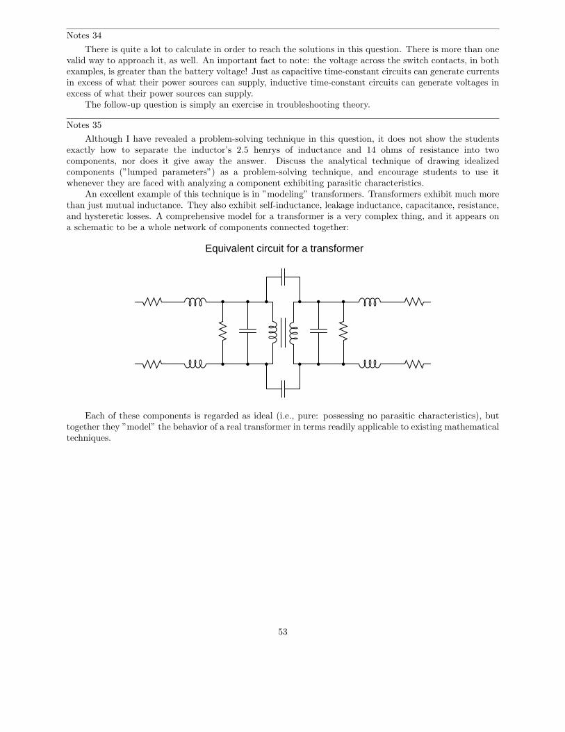
Although I have revealed a problem-solving technique in this question, it does not show the studentsexactly how to separate the inductor’s 2.5 henrys of inductance and 14 ohms of resistance into twocomponents, nor does it give away the answer. Discuss the analytical technique of drawing idealizedcomponents (”lumped parameters”) as a problem-solving technique, and encourage students to use itwhenever they are faced with analyzing a component exhibiting parasitic characteristics.
An excellent example of this technique is in ”modeling” transformers. Transformers exhibit much morethan just mutual inductance. They also exhibit self-inductance, leakage inductance, capacitance, resistance,and hysteretic losses. A comprehensive model for a transformer is a very complex thing, and it appears ona schematic to be a whole network of components connected together:
Equivalent circuit for a transformer
Each of these components is regarded as ideal (i.e., pure: possessing no parasitic characteristics), buttogether they ”model” the behavior of a real transformer in terms readily applicable to existing mathematicaltechniques.
53
Notes 36
In my experience, most American high school graduates are extremely weak in logarithms. Apparentlythis is not taught very well at the high school level, which is a shame because logarithms are a powerfulmathematical tool. You may find it necessary to explain to your students what a logarithm is, and exactlywhy it ”un-does” the exponent.
When forced to give a quick presentation on logarithms, I usually start with a generic definition:
Given: ba = c
Logarithm defined: logb c = a
Verbally defined, the logarithm function asks us to find the power (a) of the base (b) that will yield c.
Next, I introduce the common logarithm. This, of course, is a logarithm with a base of 10. A few quickcalculator exercises help students grasp what the common logarithm function is all about:
log 10 =
log 100 =
log 1000 =
log 10000 =
log 100000 =
log1
10=
log1
100=
log1
1000=
After this, I introduce the natural logarithm: a logarithm with a base of e (Euler’s constant):
Natural logarithm defined: lnx = loge x
Have your students do this simple calculation on their calculators, and explain the result:
ln 2.71828 =
Next comes an exercise to help them understand how logarithms can ”undo” exponentiation. Have yourstudents calculate the following values:
e2 =
e3 =
e4 =
54

Now, have them take the natural logarithms of each of those answers. They will find that they arriveat the original exponent values (2, 3, and 4, respectively). Write this relationship on the board as such foryour students to view:
ln e2 = 2
ln e3 = 3
ln e4 = 4
Ask your students to express this relationship in general form, using the variable x for the power insteadof an actual number:
ln ex = x
It should now be apparent that the natural logarithm function has the ability to ”undo” a power of e.Now it should be clear to your students why the given sequence of algebraic manipulations in the answer forthis question is true.
Notes 37
In developing equations, students often feel ”abandoned” if the instructor does not provide an answerfor them. How will they ever know if their equation is correct? If the phenomenon the equation seeks topredict is well-understood, though, this is not a problem.
Notes 38
In order for students to solve this problem, they must algebraically manipulate the ”normal” time-constant formula to solve for time instead of solving for voltage.
Notes 39
In order for students to solve this problem, they must algebraically manipulate the ”normal” time-constant formula to solve for time instead of solving for voltage.
Notes 40
This question incorporates electrical safety into an RC circuit time calculation. Safety is somethingyou should periodically revisit with your students, because it is so important. Ask your students how a”safe” value of voltage may be determined, and if there are any environmental circumstances impacting thisdetermination.
Notes 41
This circuit demands careful pre-analysis of the initial and final values. If students experience difficultycalculating the voltage and current figures here, it is probably due to incorrect initial and final values forvoltage and/or current.
Notes 42
Some students may write 5.17 seconds as the time required to charge to 40 volts (5 time constants’ worthof time). If so, remind them that the ”standard” of 5τ is arbitrary, and that theoretically the capacitor never
actually reaches full charge.
Notes 43
Ask your students to show how they algebraically solved the standard time constant equation for t usinglogarithms.
55

Notes 44
Ask your students to explain how they set up each calculation.
Notes 45
The follow-up question illustrates an important mathematical principle regarding logarithmic decayfunctions: for every passing of a fixed time interval, the system decays by the same factor. This is mostclearly (and popularly) seen in the concept of half-life for radioactive substances, but it is also seen here forRC (or LR) circuits.
Notes 46
In order for students to solve this problem, they must algebraically manipulate the ”normal” time-constant formula to solve for time instead of solving for voltage.
Notes 47
Although it may seem premature to introduce the 555 timer chip when students are just finishing theirstudy of DC, I wanted to provide a practical application of RC circuits, and also of algebra in generatinguseful equations. If you deem this question too advanced for your student group, by all means skip it.
Incidentally, I simplified the diagram where I show the capacitor discharging: there is actually anothercurrent at work here. Since it wasn’t relevant to the problem, I omitted it. However, some students may beadept enough to catch the omission, so I show it here:
555Disch
Thresh
Trig
Gnd
Vcc RST
Out
Ctrl
R1
R2
C
Capacitor discharging through R2 only
Note that this second current (through the battery) does not go anywhere near the capacitor, and so isirrelevant to the discharge cycle time.
Notes 48
Some students may think that a rate of change of 4.44 kilovolts per second harbors shock hazard,because, well, 4.44 thousand volts is a lot of voltage! Remind them that this is a rate of change and not anactual voltage figure. This number simply tells us how fast the voltage is changing, not how far it will riseto. It is the difference between saying that a car travels at 75 miles per hour and that a car will travel 75miles.
56

Notes 49
Some students may think that a rate of change of 280 amps per second might burn up the wiring,because 280 amps seems like a lot of current. Remind them that this is a rate of change and not an actualcurrent figure. This number simply tells us how fast the current is changing, not how far it will rise to. It isthe difference between saying that a car travels at 75 miles per hour and that a car will travel 75 miles.
Notes 50
L/R time constant circuits are an excellent example of how to apply simple differential equations. In thiscase, we see that the differential equation is first-order, with separable variables, making it comparativelyeasy to solve.
It should also be evident to students that any initial condition for current may be set into the generalsolution (by changing the value of the constant).
Notes 51
RC time constant circuits are an excellent example of how to apply simple differential equations. In thiscase, we see that the differential equation is first-order, with separable variables, making it comparativelyeasy to solve.
It should also be evident to students that any initial condition of capacitor charge may be set into thegeneral solution (by changing the value of the constant).
57
Notes 52
It has been my experience that students require much practice with circuit analysis to become proficient.To this end, instructors usually provide their students with lots of practice problems to work through, andprovide answers for students to check their work against. While this approach makes students proficient incircuit theory, it fails to fully educate them.
Students don’t just need mathematical practice. They also need real, hands-on practice building circuitsand using test equipment. So, I suggest the following alternative approach: students should build theirown ”practice problems” with real components, and try to mathematically predict the various voltage andcurrent values. This way, the mathematical theory ”comes alive,” and students gain practical proficiencythey wouldn’t gain merely by solving equations.
Another reason for following this method of practice is to teach students scientific method: the processof testing a hypothesis (in this case, mathematical predictions) by performing a real experiment. Studentswill also develop real troubleshooting skills as they occasionally make circuit construction errors.
Spend a few moments of time with your class to review some of the ”rules” for building circuits beforethey begin. Discuss these issues with your students in the same Socratic manner you would normally discussthe worksheet questions, rather than simply telling them what they should and should not do. I nevercease to be amazed at how poorly students grasp instructions when presented in a typical lecture (instructormonologue) format!
A note to those instructors who may complain about the ”wasted” time required to have students buildreal circuits instead of just mathematically analyzing theoretical circuits:
What is the purpose of students taking your course?
If your students will be working with real circuits, then they should learn on real circuits wheneverpossible. If your goal is to educate theoretical physicists, then stick with abstract analysis, by all means!But most of us plan for our students to do something in the real world with the education we give them.The ”wasted” time spent building real circuits will pay huge dividends when it comes time for them to applytheir knowledge to practical problems.
Furthermore, having students build their own practice problems teaches them how to perform primary
research, thus empowering them to continue their electrical/electronics education autonomously.In most sciences, realistic experiments are much more difficult and expensive to set up than electrical
circuits. Nuclear physics, biology, geology, and chemistry professors would just love to be able to have theirstudents apply advanced mathematics to real experiments posing no safety hazard and costing less than atextbook. They can’t, but you can. Exploit the convenience inherent to your science, and get those students
of yours practicing their math on lots of real circuits!
58
![QUn'i&~illltlnacademic.udru.ac.th/~banyat/EIT_telecom/T_telecom.pdftacan (tactical air navigation! ... time constant of fall [pulse] A1IN«1111" 11a1lHl-ln1~iHlai . time constant of](https://static.fdocuments.us/doc/165x107/5b07a6f07f8b9a520e8b703c/quni-banyateittelecomttelecompdftacan-tactical-air-navigation-time.jpg)