timber - NoIS
31
Timber Module 1 Timber Module 1 Introduction ................................................................................................ 5 1.1 General ................................................................................................. 5 1.2 Restrictions .......................................................................................... 5 2 Program structure ...................................................................................... 7 2.1 Design .................................................................................................. 7 2.2 Input ..................................................................................................... 8 2.2.1 Member ......................................................................................... 8 2.2.2 Load case ....................................................................................... 8 2.2.3 Support conditions ........................................................................ 9 2.2.4 Lateral supports ........................................................................... 10 2.2.4.1 Continuous supports ............................................................ 11 2.2.4.2 Single supports ..................................................................... 11 2.2.5 Load level .................................................................................... 12 2.2.6 Details ......................................................................................... 13 2.2.7 Deflection check ......................................................................... 16 2.3 Results ................................................................................................ 16 2.3.1 Material ....................................................................................... 16 2.3.2 Section values ............................................................................. 16 2.3.3 Capacity ...................................................................................... 17 2.3.4 Code Check ................................................................................. 18 2.3.5 Quick way to change section ...................................................... 21 2.3.6 Utilization colours ....................................................................... 22 2.3.7 Utilization table ........................................................................... 22 2.4 Option ................................................................................................ 23 2.4.1 Lateral supports ........................................................................... 23 2.4.2 Section image .............................................................................. 23 3 Methods of calculation ............................................................................. 25 3.1 Design methods with regard to buckling ........................................... 25 3.1.1 First Order Theory ...................................................................... 25 3.1.2 Second Order Theory .................................................................. 25 3.2 Axial force capacity ........................................................................... 26 3.3 Moment capacity ................................................................................ 26 3.3.1 Lateral torsional buckling ........................................................... 27 3.4 Shear capacity .................................................................................... 29
Transcript of timber - NoIS

Timber Module1 Introduction ................................................................................................ 5
1.1 General ................................................................................................. 51.2 Restrictions .......................................................................................... 5
2 Program structure ...................................................................................... 72.1 Design .................................................................................................. 72.2 Input ..................................................................................................... 8
2.2.1 Member ......................................................................................... 82.2.2 Load case ....................................................................................... 82.2.3 Support conditions ........................................................................ 92.2.4 Lateral supports ........................................................................... 10
2.2.4.1 Continuous supports ............................................................ 112.2.4.2 Single supports ..................................................................... 11
2.2.5 Load level .................................................................................... 122.2.6 Details ......................................................................................... 132.2.7 Deflection check ......................................................................... 16
2.3 Results ................................................................................................ 162.3.1 Material ....................................................................................... 162.3.2 Section values ............................................................................. 162.3.3 Capacity ...................................................................................... 172.3.4 Code Check ................................................................................. 182.3.5 Quick way to change section ...................................................... 212.3.6 Utilization colours ....................................................................... 222.3.7 Utilization table ........................................................................... 22
2.4 Option ................................................................................................ 232.4.1 Lateral supports ........................................................................... 232.4.2 Section image .............................................................................. 23
3 Methods of calculation ............................................................................. 253.1 Design methods with regard to buckling ........................................... 25
3.1.1 First Order Theory ...................................................................... 253.1.2 Second Order Theory .................................................................. 25
3.2 Axial force capacity ........................................................................... 263.3 Moment capacity ................................................................................ 26
3.3.1 Lateral torsional buckling ........................................................... 273.4 Shear capacity .................................................................................... 29
Timber Module 1

4 References .................................................................................................. 31
2 Timber Module

Info
Timber Module 6.0
Copyright: Structural Design Software in Europe AB
Datum: 110930
Latest information about programs from WIN-Statik and FEM-Design see
www.strusoft.com
Timber Module - Info 3

4 Timber Module - Info

1 Introduction
1.1 GeneralWith the program Timber Module continuous beams and plane frame struc-tures can be designed according to EuroCode EC5. The Timber Module is usedtogether with the program Frame Analysis in which calculations of sectionforces is performed.
Design with consideration taken to flexural buckling in the frame plane can beperformed for second order theory or for first order theory with help from buck-ling lengths defined by the user.
Continuous support, as well as support in certain points of the beam as well astransverse stiffeners for open cross-sections can be defined.
The program displays all code prescribed checks depending on type of sectionand current load.
1.2 RestrictionsSupport conditions can be defined as hinged, fixed or free edge with consider-ation to buckling and lateral instability.
Important! A node defined with the Member tool will automatically be consid-ered laterally restrained with respect to flexural buckling out of the frame planeat a possible design. Control of instability out of the frame´s plan is then per-formed with regard to these defined support conditions.
With the help of the support conditions for each node specified under the optionSupport Conditions equal to one of four Euler buckling cases a reduction fac-tor for flexural buckling, torsional buckling or flexural torsional buckling is cal-culated and the most dangerous value is chosen. These support conditions arealso used for calculating lateral torsional buckling.
Timber Module - Introduction 5

The conditions for the program are such that each node is assumed supportedout of the plane in such a way that corresponds to one of these buckling cases.
If a larger buckling length with regard to instability out of the plane than whatcorresponds to one of the above buckling cases can be assumed, the node shouldinstead be defined with the tool Unsupported joint.
The node is then only considered to have sufficient torsional stiffness to be as-sumed as a hinged support with regard to lateral torsional buckling and flexuralbuckling is calculated for a buckling length assumed to extend between the near-est supported nodes. If with the above procedure it is not possible to adequatelymodel the reality regarding instability out of the plane, the calculation can alter-natively be supplemented with a 2-dimensional calculation also perpendicular tothe frame plane.
6 Timber Module - Introduction

2 Program structure
2.1 DesignWhen the calculation has been completed the Design program mode is enabled,and the appearance of the main menu changes as seen below. The Design optionin the main menu makes it possible to define any additional information thatmay occur for a design check as well as study the results of the calculation.
Note! This mode is only available if Timber Module has been installed.
Timber Module - Program structure 7
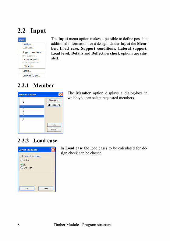
2.2 InputThe Input menu option makes it possible to define possibleadditional information for a design. Under Input the Mem-ber, Load case, Support conditions, Lateral support,Load level, Details and Deflection check options are situ-ated.
2.2.1 MemberThe Member option displays a dialog-box inwhich you can select requested members.
2.2.2 Load caseIn Load case the load cases to be calculated for de-sign check can be chosen.
8 Timber Module - Program structure

2.2.3 Support conditions
In the Support conditions dialog buckling lengths are defined regarding buck-ling in the frame plane if the analysis has been performed according to 1st ordertheory. Here is also support conditions regarding buckling out of frame plane de-fined. Initially all members defined with the tool Member in Frame Analysis issupposed to have hinged support conditions at both ends. This means that thebuckling length is equal to the member length.
Note! A joint that has been defined with the tool Member will automatically beregarded as supported with regard to buckling out of the frame plane. If no later-al support with regard to flexural buckling is expected the tool Unsupportedjoint should be used instead.
If design is performed according to 2nd order theory only support conditions re-garding buckling out of frame plane should be defined.
Timber Module - Program structure 9
When defining, only the active member or selected members are affected de-pending on what is defined above. In the above picture only 1 member is select-ed which is seen in the title row of the dialog. In order to make it possible todefine support conditions at least one member must be selected. To make it pos-sible to define a free end the other end must be fixed.
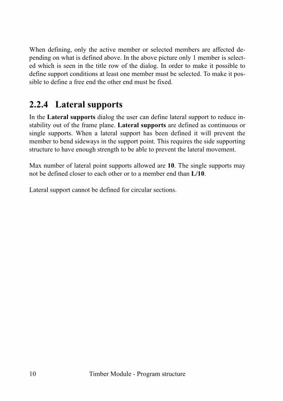
2.2.4 Lateral supportsIn the Lateral supports dialog the user can define lateral support to reduce in-stability out of the frame plane. Lateral supports are defined as continuous orsingle supports. When a lateral support has been defined it will prevent themember to bend sideways in the support point. This requires the side supportingstructure to have enough strength to be able to prevent the lateral movement.
Max number of lateral point supports allowed are 10. The single supports maynot be defined closer to each other or to a member end than L/10.
Lateral support cannot be defined for circular sections.
10 Timber Module - Program structure

2.2.4.1 Continuous supports
Continuous supports can be defined for one or both edges of the section.
In the above dialogs the top edge of a beam member (member 5) and the rightside of a column member (member 3) are defined continuously supported in theweak direction.
What is defined will only affect the active member or the chosen members de-pending on the above choice.
2.2.4.2 Single supportsSingle supports can be defined for one or both edges of the section. Maximumnumber of supports is 10. The supports must not be situated closer to each otheror to a member end than L/10.
Timber Module - Program structure 11

In the above dialog the upper edge of a beam element is supported at four pointssituated 1,0 m, 2,0 m 3,0 and 4.0 m from the left member end.
2.2.5 Load levelFor members sensitive to lateral torsionalbuckling the capacity depends on the levelwhere the loads are situated.
In the dialog is shown how the load level isdefined. The program knows in what direc-tion the loads act and can place the load ac-cordingly.
12 Timber Module - Program structure

2.2.6 DetailsWhen the option Details is chosen a window showing the current member ispresented as a beam or a column.
Details can only be defined if the member's stiff direction is in the frame plane.From the picture above the current support conditions can be seen.
The picture above shows a column member where the left edge is defined con-tinuously supported. For a continuously supported edge the supports are as-
Timber Module - Program structure 13

sumed to be situated so closely along the whole member that no instability canoccur between the supports.
If both edges are continuously supported, no flexural buckling in the weak di-rection, flexural-torsional buckling or lateral torsional buckling can occur. Ifonly one edge is supported flexural-torsional buckling can occur.
For lateral torsional buckling the capacity depends on how large part of the sup-ported edge that is in compression. If an edge is in compression along the entiremember and continuously supported no lateral torsional buckling is possible butif the supported edge is in tension the capacity is calculated with regard to this.The connection between the supports and the member is assumed to be hinged.
The picture above shows single supports at the top edge for a beam member. orsingle supports instability between these supports can occur. When calculatingthe capacity due to pure flexural buckling in the weak direction the bucklinglength is calculated with regard to all single supports regardless which edgethese are situated on. For flexural-torsional buckling the buckling length is cal-culated with regard to single supports situated at the same edge and the maxi-mum length from the two edges will be decisive.
The capacity due to lateral torsional buckling is only dependent of single sup-ports defined at an edge in compression for the current load case. No consider-ation to possible supports defined at an edge in tension.
14 Timber Module - Program structure

For a beam member with moment distribution and lateral support as above noconsideration is made to the rightmost support concerning lateral torsional buck-ling as the top edge is in tension at this point. The calculation will thus be madefor three areas with length 2,0 m, 2,0 m and 4,0 m. If single supports are definedat an edge which is totally or partly in compression no consideration is made toa possible continuous support at the other edge.
The calculation of the elastic critical lateral torsional buckling moment assumesa linearly varying moment distribution between the supports. A check is there-fore made if the supports are situated close enough for such an assumption.
The picture shows how buckling stiffeners are displayed for a beam member.
Timber Module - Program structure 15

2.2.7 Deflection checkIn the Deflection check dialog adeflection check for active or se-lected members are defined. Thedeflection check can then be per-formed with respect to a factor ofcurrent span length or a stated val-ue.
In the latter case the same criterion will be used for all selected members.
2.3 ResultsThe Results menu option makes it possible tostudy the results generated by the calculation.Under Results the following options can befound: Material, Section values, Capacity,Code check, Utilization colours and Utilizationtable. The remaining options are only relevantfor concrete members.
2.3.1 MaterialMaterial design strengths are shown in the Material dialog box.
2.3.2 Section valuesThe Section values option displays a graphic picture of the current profile withassociated geometrical properties and the calculated section classes.
16 Timber Module - Program structure

In the above picture a section with section values is shown.
2.3.3 CapacityThe Capacity option displays a dialog box where the capacity of the activemember with regard to instability corresponding to the current section forces isdisplayed. What is shown depends on section type, loading and possible lateralbracing. Below the appearance of the capacity dialog box for some cases areshown:
Moment and shear force in stiff direction. Unsupported member. Rectangularsection.
Timber Module - Program structure 17

In the above picture the critical lateral torsional buckling moment and the reduc-tion factor with regard to lateral torsional buckling are shown together with thevalue of the reduction factor with regard to shear.
Axial force and moment in stiff direction. Unsupported member. Rectangularsection.
Above is shown the capacity window for a 1th order design. lcr,y/lcr,z/lcr,T are thebuckling lengths and kc,y/kc,z/kc,T are the reduction factor for flexural and tor-sional buckling respectively.
2.3.4 Code Check
The Code Check option displays for the active member at Ultimate Limit Stateall capacity checks according to EC5 as well as a possible deflection check forthe Serviceability Limit State. It is also shown where the most critical section is
18 Timber Module - Program structure

located, and if upper or lower edge is critical. For vertical members the rightside corresponds to the upper edge. What is displayed depends on section type,loading and possible lateral bracing. Checks that might indicate that the load-bearing capacity is insufficient are shown with red text. The sum of the interac-tion formula displayed is the maximum value along the member length for thecurrent load case.
If more than one load case is defined the maximum utilization with regard to allload cases are displayed for each code check and also which load case that is de-cisive.
Moment and shear force in stiff direction. Unsupported member. Rectangularsection.
Timber Module - Program structure 19

Axial force, moment and shear force in stiff direction. Unsupported member.Rectangular section. 1th order design.
Axial force, moment and shear force in stiff direction. Unsupported member.Rectangular section. 2nd order design.
In this case no flexural buckling check in the plane of the frame is made as thestress check is also a buckling check as the stress is calculated with regard to 2nd
order moments.
20 Timber Module - Program structure

2.3.5 Quick way to change sectionIn the Code check dialog box it is also possible to change section temporarily.This is very useful if the capacity is inadequate in order to quickly find a sectionwith sufficient capacity.
Above the current section 140 x 585 is inadequate.
It is possible to change section within the same section type.
By changing to a 140 x 675 the capacity is sufficient for the current load case.
Timber Module - Program structure 21

Warning!Changing the section in the code check window means that a new design ismade but the analysis is the same although the stiffness distribution in the struc-ture has changed. The ability of section change has been created for the user toquickly find an appropriate section but then a new analysis has to be performedwith the new sections. The program will therefore change back to the originalsection when the code check dialog window is closed.
2.3.6 Utilization coloursWhen the design has been completed the included members will get differentcolours depending on how the result turns out. The members that pass all checkswill get a green colour and the others will get a red colour as default.
Members can also be coloured blue according to the Utilization ratio-coloursoption. The purpose with this can e.g. be to swiftly survey, not only which mem-bers will pass but also to see which members are being utilized over a user-givenlimit.
In the picture above an example is shownwhere all members that are being utilized lessthan 50% are being green coloured, those thatare being utilized 50-100% are being blue co-loured, and those that don't have enough ca-pacity are being red coloured.
2.3.7 Utilization tableIn order to quickly get an opinion ofthe utilization in different parts of thestructure the Utilization ratio-tableoption can be used. A table is dis-played, showing the utilization valuefor all members. The table can be sort-ed according to utilization or membernumber.
22 Timber Module - Program structure

2.4 Option
2.4.1 Lateral supportsIt is possible to support the mem-bers laterally continuously or with simple supports. If the op-tion Lateral support in the menu Option is activated this lateral bracing is displayed as shown below:
If a number of members are sup-ported simultaneously the top edge for a horizontal member corresponds to the right edge for a vertical member.
2.4.2 Section imageIf the option Section image in the menu Option is activated the section for eachmember will be displayed as for the figure.
Timber Module - Program structure 23

24 Timber Module - Program structure

3 Methods of calculation
3.1 Design methods with regard to bucklingThe design is being performed according to [1] along with all code prescribedchecks depending on section type, section class and loading. Flexural bucklingin the frame plane can be performed according to 1th or 2nd order theory. Forbuckling out of the plane frame 1th order theory is used. The user decide desiredmethod in Frame Analysis.
3.1.1 First Order TheoryThe following are valid when designing according to the first order theory:
The capacity with regard to flexural buckling is calculated according to [1]6.3.2. In the frame plane the buckling length is defined by the user and out of theplane the buckling length is calculated from support conditions defined by theuser. The effect of initial bow imperfection is already considered and has not tobe defined separately but the effect of possible deviation has to be considered byhorizontal loads.
3.1.2 Second Order TheoryThe second order theory considers the influence of deflection on force and mo-ment distribution within the frame. There is no need to define buckling lengthsin the frame plane when using this method since the buckling effect will be con-sidered with the second order moments in the members. The capacity with re-gard to flexural buckling in the frame plane is shown with the maximum stresscheck in the code check window with regard to 2nd order moments. When allmembers pass the code checks there will be enough buckling safety within theframe plane for each member as well as for the frame as a whole.
Calculations according to the second order theory must have been selected inFrame Analysis in order to perform the design in this way in Timber Module.When using this method the following demands must be fulfilled:
Timber Module - Methods of calculation 25

Consideration shall be taken to initial bow imperfections. Use the tool ”Initialbow imperfection” in Frame Analysis to state which members shall have initialcurvature due to imperfection. It is particularly important for hinged membersloaded with axial force only otherwise there will be no effect from 2nd order mo-ments. Therefore no design is allowed for compression members if the 1th ordermoment does not correspond to the initial bow imperfection moment.
When working with sway-frames (or isolated columns) consideration must alsobe taken to initial deviation from the vertical loads of the frame. Frame Analy-sis will not automatically consider this, so the user must choose another methodin order to include effect of initial deviation. A suitable method is to add fictivehorizontal loads corresponding to the effect of the deviation.
With regard to instability out of the frame plane, also a flexural and a flexuraland lateral torsional buckling check is made unless the member is preventedfrom lateral movement by lateral bracing.
Instability out of the frame plane is also affected from the support conditions de-fined by the user under the option Support conditions. As default it is pre-sumed that all members are hinged at both ends.
3.2 Axial force capacityThe capacity for members in tension and compression is calculated according to[1] 6.1.2-5.
The capacity for compressed members is calculated with regard to flexuralbuckling and possible torsional buckling.
The member can be laterally supported continuously or at certain points in orderto increase the capacity with regard to instability out of the frame plane.
3.3 Moment capacityThe capacity is calculated according to [1] 6.3.3.
26 Timber Module - Methods of calculation

3.3.1 Lateral torsional bucklingLateral torsional buckling is calulated for rectangular massive sections, I-sec-tions, rectangular hollow sections and U-sections if the height > width.
The reduction factor with regard to lateral torsional buckling is calculated ac-cording to [1] 6.3.3.
The elastic critical moment for lateral torsional buckling Mcr is calculated as de-scribed below.
Elastic critical moment for lateral-torsional buckling Mcr
When calculating lateral-torsional buckling it is required to find the critical mo-ment Mcr for arbitrary sections, where the moment distribution and support con-ditions greatly influences the result. A theoretical solution could be written as:
Mcr = m / L (E0,05 Iz G0,05 ITor)0,5
Where m is a coefficient depending on the section type, loading, support condi-tions and load level and κ is depending on the support conditions.
ITor is the torsional constant.
It is however in most cases not possible to find a theoretical solution for the crit-ical moment Mcr for arbitrary sections, loading situations and support condi-tions.
Present solutionIn the timber design module routines to calculate the critical moment is usedwhere a method to transfer the current case to a case with a known theoreticalsolution is the so called "Deflection analogy" where the deflection for the mem-ber as simply supported with the current load situation is compared to deflectionfor a standard load in this case a uniform load. To consider different momentdistributions, support conditions and load levels [4] and [5] are used. As the cen-tre of gravity of the load action along the member is important especially whenthe support conditions differ between the edges, this point is calculated and thecritical moment is influenced accordingly.
Timber Module - Methods of calculation 27

The following moment types will be used in the calculation:
No consideration is taken to an in-creased critical moment due to thecontinuity between members buteach member is treated as simplysupported, however with regard tothe actual moment distribution.Defining fixed support conditionscan also increase the critical mo-ment.
Moment types 1,2 and 6The current load case is transferred to the case uniform distributed load by thedeflection analogy. The load level in this case influences the critical moment.The capacity could be increased by fixed support conditions in the weak direc-tion at one or both ends. If only one end is fixed the calculation will also consid-er the position of the centre of gravity for the current load case with regard to thefixed end.
For moment type 2, if only one end is fixed the critical moment will differ de-pending on if the support moment is situated at the fixed end or not.
For moment type 2 and 6 the critical moment is influenced by the relation be-tween the magnitudes of the positive and the negative moments.
Moment types 3,4 and 5For these types the calculation is made for a linear moment distribution, wherethe relation between the magnitudes of the end moments highly influences theresult. The critical moment could be increased by fixed support conditions in theweak direction at one or both ends. If only one end is fixed the capacity will dif-fer depending on if the largest moment is situated at the fixed end or not.
For a cantilever the current load case is transferred for moment type 3 to the caseuniform distributed load by the deflection analogy. The load level will in thiscase influence the critical moment.
28 Timber Module - Methods of calculation
For moment type 4 the calculation for a cantilever will be performed as for amember hinged at both ends with double length.
3.4 Shear capacityThe capacity is calculated according to [1] 6.1.7. An effective width bef = 0,67 bis used but can be adjusted if the user not want to follow the code in this respect.
Timber Module - Methods of calculation 29

30 Timber Module - Methods of calculation

4 References1. EN 1995-1-1 Design of timber structures – Part 1-1: General rules and ru-
les for buildings.
2. Structural Timber Design to Eurocode 5. Porteous and Kermani. 2007.
3. Limträhandboken, Svenskt Limträ, 2008.
4. Handboken Bygg, Allmänna grunder, Avsnitt A30, Stockholm, 1985.
5. Knäckning Vippning Buckling, StBK-K2, Statens Stålbyggnadskommitte,1973.
Timber Module - References 31