Tightness control TC - tsolution.kr · Tightness control TC. 2 · TC · Edition 12.07 TC 1, TC 2 TC...
12
3.1.5.2 Edition 12.07 Product brochure · GB www.kromschroeder.com Test of both safety valves • Short test period thanks to logical decision-making • in the program sequence Adjustable test period which can be adapted • to different systems Adjustable test mode allows quick system start • Maximum safety thanks to self-monitoring electronics • Less space required thanks to small dimensions • EC type-tested and certified • FM and UL approved • Tightness control TC
Transcript of Tightness control TC - tsolution.kr · Tightness control TC. 2 · TC · Edition 12.07 TC 1, TC 2 TC...

3.1.5.2 Edition 12.07Product brochure · GB
www.kromschroeder.com
Test of both safety valves•
Short test period thanks to logical decision-making •in the program sequence
Adjustable test period which can be adapted •to different systems
Adjustable test mode allows quick system start•
Maximum safety thanks to self-monitoring electronics•
Less space required thanks to small dimensions•
EC type-tested and certified•
FM and UL approved•
Tightness control TC

2 · TC · Edition 12.07
TC 3 TC 4TC 1, TC 2
ApplicationThe tightness control TC checks the fail-safe function of both valves before each start-up or after each shut-down of a system with two safety valves.
The aim is to identify an inadmissible leak on one of the gas valves and to prevent burner start. The other gas valve continues working properly and takes over the safe shut-off of the gas supply.
It is used in industrial thermoprocessing equipment, in boilers and forced draught burners.
European standards EN 746-2 and EN 676 stipulate tightness controls for capacities over 1200 kW (NFPA 86: from 117 kW or 400,000 Btu/h in conjunction with a visual indicator). Pre-purge of the combustion chamber can be dispensed with under cer-tain conditions in accordance with EN 746-2, if a tightness control is used. In this case, the system must be vented into the open air.
TC 1Tightness control TC 1 can be directly mount-ed to all CG combination controls. There is only one version for all sizes. The pre-set test period applies to all CG variants.
In addition, TC 1 can be used for valVario controls VAS, VAD and VAG (with separate adapter plate).
TC 2 and TC 4Tightness controls TC 2 and TC 4 can be used with gas solenoid valves of any nominal size, which are quick opening or slow opening with start rate. It is possible to conduct a tight-ness test on pneumatically operated or slow opening valves without start rate by using additional auxiliary valves.
Slow opening motorised valves VK up to DN 65 which are directly flanged together can also be checked by TC 2 and TC 4 within a temperature range of 0 to 60°C (32 to 140°F).
TC 4Tightness control TC 4 consists of detection circuitry and can be installed in the control cabinet, separately from the system. An external pressure switch takes over the mechanical pressure test between the valves. Tightness control TC 4 is independent of gas type and inlet pressure pe and can be used for a test period of up to 10 minutes with a large test volume.
TC 3Tightness control TC 3 is a universal device for quick and slow opening gas solenoid valves of any nominal size as well as for motorised valves. The tightness test is carried out with the valves installed in TC 3.
TC 1: for attachment to valVario controls
and CG TC 2: for quick open-ing individual valves
TC 3: for quick or slow opening or manually resettable individual valves TC 4: for control cabinet installation

TC · Edition 12.07 · 3
TC 1 mounted to a combination
control CG
TC 4 installed separately from the system in a control cabinet
TC 3 on a heating boiler
TC 2 in a gas inlet section between a quick opening and a slow opening gas solenoid valve VG
TC 4 installed in control cabinet securing the lower section with screws or snapping it on to a DIN rail
TC 3 for tightness control on gas motorised valve VK

4 · TC · Edition 12.07
L1(+)N(-)PE
OK
V1 V2
pe
pZ
VP
CG
TC 1
GFA
1 2 3
1 2 3
TC 116W
1 3 5 6
V1 V2CG
L1(+)N(-)PE
OK
V1VAS VAD
V2pe
GFA
1 2 3
1 2 3
TC 116V
1 3 5 6
V1 V2
pe pZ
VP
TC 1
L1(+)N(-)PE
OK
V1 V2VZ
pe
pZ
VP
CG..Z
TC 1
GFA
1 2 3
1 2 3
TC 116W
1 3 5 6
1 2 3
V1 V2CG..Z
VZ
TC 116V with valVario controlsTightness control TC 1 checks gas solenoid valves V1 and V2 for tight-ness.
If both valves are tight, the tightness control forwards the OK enable signal to the automatic burner control unit GFA. This opens valves V1 and V2 simultaneously. The burner starts.
V1 and V2: quick or slow opening valves with start rate.
TC 116W with combination control CG..D or CG..VThe tightness control is directly mounted to combination control CG..D or CG..V.
Once the tightness test has been carried out successfully, the tight-ness control forwards the OK enable signal to the automatic burner control unit GFA. This opens valves V1 and V2 in the combination control CG simultaneously. The burner starts.
V1 and V2: quick opening valves.
TC 116W with two-stage combination control CG..ZOnce the tightness test has been carried out successfully, the tightness control forwards the OK enable signal to the automatic burner control unit GFA. The pilot valve output of the automatic burner control unit GFA opens valves V1 and V2 in the combination control simultane-ously. The burner starts. The main valve output opens the two-stage valve VZ, independently of TC 116W.
V1 and V2: quick opening valves.
Examples of application

TC · Edition 12.07 · 5
L1(+)N(-)PE
OK
V1 V2
pe
pe pZ
VP
TC 2
GFA
1 2 3
1 2 3
TC 2
1 3 5 6
V1 V2
V1 V2
V3
pe
pe pZ
VP
TC 2
L1(+)N(-)PE
OKGFA
1 2 3
1 2 3
TC 2
1 3 5 6
V1 V3 V2
TC 2 with two gas solenoid valvesTightness control TC 2 checks gas solenoid valves V1 and V2 for tightness.
If both valves are tight, the tightness control forwards the OK enable signal to the automatic burner control unit GFA. This opens valves V1 and V2 simultaneously. The burner starts.
V1 and V2: quick or slow opening valves with start rate.
TC 2 with two gas solenoid valves and one pilot gas valveTightness control TC 2 checks the gas solenoid valves for tightness. The test volume is discharged into the combustion chamber. Auxiliary valve V3 can be used as a pilot gas valve.
Once the tightness test has been carried out successfully, the tightness control forwards the OK enable signal to the automatic burner control unit GFA. The pilot valve output of the automatic burner control unit GFA opens the gas solenoid valves V1 and V3 simultaneously. The main valve output opens gas solenoid valve V2. The burner starts.
V1 and V2: quick or slow opening valves with start rate. V3: quick opening, minimum nominal size = DN 15.
6 · TC · Edition 12.07
V1 V2
V3pe
pe pZTC 2
L1(+)N(-)PE
OKGFA
1 2 3
1 2 3
TC 2
1 3 5 6
V1 V3 V2
VP
V1
pe
pe pZ
L1(+)N(-)PE
OK
1 2 3
1 2 3
TC 2
1 3 5 6
V3 V4
VAS
DG
K1
TC 2
VP
V4
V2
V3
V2
V1
K1
VAS
DG
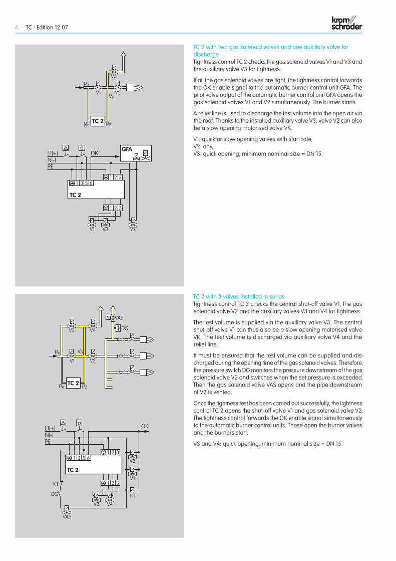
TC 2 with two gas solenoid valves and one auxiliary valve for dischargeTightness control TC 2 checks the gas solenoid valves V1 and V2 and the auxiliary valve V3 for tightness.
If all the gas solenoid valves are tight, the tightness control forwards the OK enable signal to the automatic burner control unit GFA. The pilot valve output of the automatic burner control unit GFA opens the gas solenoid valves V1 and V2 simultaneously. The burner starts.
A relief line is used to discharge the test volume into the open air via the roof. Thanks to the installed auxiliary valve V3, valve V2 can also be a slow opening motorised valve VK.
V1: quick or slow opening valves with start rate, V2: any, V3: quick opening, minimum nominal size = DN 15.
TC 2 with 3 valves installed in seriesTightness control TC 2 checks the central shut-off valve V1, the gas solenoid valve V2 and the auxiliary valves V3 and V4 for tightness.
The test volume is supplied via the auxiliary valve V3. The central shut-off valve V1 can thus also be a slow opening motorised valve VK. The test volume is discharged via auxiliary valve V4 and the relief line.
It must be ensured that the test volume can be supplied and dis-charged during the opening time of the gas solenoid valves. Therefore, the pressure switch DG monitors the pressure downstream of the gas solenoid valve V2 and switches when the set pressure is exceeded. Then the gas solenoid valve VAS opens and the pipe downstream of V2 is vented.
Once the tightness test has been carried out successfully, the tightness control TC 2 opens the shut-off valve V1 and gas solenoid valve V2. The tightness control forwards the OK enable signal simultaneously to the automatic burner control units. These open the burner valves and the burners start.
V3 and V4: quick opening, minimum nominal size = DN 15.

TC · Edition 12.07 · 7
L1(+)N(-)PE
OK
V1 V2
pe
pe pa
pZ
VP
GFA
TC 3
1 3 5 6
V2
V1
TC 3
L1(+)N(-)PE
OK
V1 V2
pe
pe pa
pZ
VP
GFA
TC 3
1 3 5 6
TC 3
V2
V1
TC 3 with two gas solenoid valvesTightness control TC 3 checks the slow opening gas solenoid valves or motorised valves VK for tightness using the auxiliary valves in-stalled in TC 3.
Once the tightness test has been carried out successfully, the tight-ness control forwards the OK enable signal to the automatic burner control unit GFA. The pilot valve output of the automatic burner control unit GFA opens the gas solenoid valves V1 and V2 simultaneously. The burner starts.
V1 and V2: any.
TC 3 with a manually resettable valveValves, which are manually reset, cannot be opened by the tightness control. The tightness test is then carried out using an additional auxiliary valve.
Tightness control TC 3 checks the tightness between the manually resettable valve V1 and gas solenoid valve V2 using the auxiliary valves installed in TC 3.
Once the tightness test has been carried out successfully, TC 3 forwards the OK enable signal.

8 · TC · Edition 12.07
V1
pe
pe pa
pZ
L1(+)N(-)PE
OK
TC 3
1 3 5 6
TC 3
VP
V2
V2
VAS
DG
V1
K1VAS
DG
K1
pe Vp
V1 V2
1 2 3 4 5 6 7 8 9 10 11 12 13
OK
DG
V2V1L1(+)N(-)
max
TC 410
pe2
GFA
TC 3 in a multiple burner systemTightness control TC 3 checks the central shut-off valve V1 and gas solenoid valve V2 for tightness. Both valves can also be motorised valves VK.
It must be ensured that the test volume can be supplied and dis-charged during the opening time of the gas solenoid valves. Therefore, the pressure switch DG monitors the pressure downstream of the gas solenoid valve V2 and switches when the set pressure is exceeded. Then the gas solenoid valve VAS opens and the pipe downstream of V2 is vented.
Once the tightness test has been carried out successfully, TC 3 opens the shut-off valve V1 and gas solenoid valve V2 and forwards the OK enable signal to the automatic burner control units. These open the burner valves and the burners start.
TC 4 with two gas solenoid valvesTightness control TC 4 checks gas solenoid valves V1 and V2 for tightness.
The external pressure switch monitors the pressure between the two valves.
Once the tightness test has been carried out successfully, the tight-ness control forwards the OK enable signal to the automatic burner control unit GFA. The pilot valve output of the automatic burner control unit GFA opens the gas solenoid valves V1 and V2 simultaneously. The burner starts.
V1 and V2: quick or slow opening valves with start rate.

TC · Edition 12.07 · 9
VpV1
V2
1 2 3 4 5 6 7 8 9 10 11 12 13
OKDG
V2V1L1(+)N(-)
max
TC 4
pe
DGpe2
VpV1
OKDG
V3
V1
V2L1(+)N(-)
max
TC 4
V3V2
pe
DGpe2
1 2 3 4 5 6 7 8 9 10 11 12 13
TC 4 in a multiple burner system with one auxiliary valve for dischargeTightness control TC 4 checks the central shut-off valve V1, the auxiliary valve V2 and several burner valves for tightness. The external pres-sure switch monitors the pressure between the gas solenoid valves V1, V2 and the burner valves.
Once the tightness test has been carried out successfully, TC 4 opens gas solenoid valve V1. The tightness control forwards the OK enable signal simultaneously to the automatic burner control units for the burner valves. The burner valves open and the burners start.
Thanks to the relief line and auxiliary valve V2, the test volume is discharged into the open air via the roof or into the combustion chamber.
V1: quick opening valve. V2: quick opening, minimum nominal size = DN 15.
TC 4 in a multiple burner system with two auxiliary valves for supply and dischargeTightness control TC 4 checks the central shut-off valve V1, auxiliary valves V2 and V3, and several burner valves for tightness.
The test volume is supplied via the auxiliary valve V2.
The external pressure switch monitors the pressure between the gas solenoid valves and the burner valves.
Once the tightness test has been carried out successfully, TC 4 opens the central shut-off valve V1. The tightness control forwards the OK enable signal simultaneously to the automatic burner control units for the burner valves. The burner valves open and the burners start.
Thanks to the relief line and auxiliary valve V2, the test volume is discharged into the open air via the roof or into the combustion chamber.
V1: any. V2 and V3: quick opening, minimum nominal size = DN 15.

10 · TC · Edition 12.07
V1
pe
VP
V4
V2
V3
VAS
DG
OKDG
V4V3 V1 V2 K1L1(+)N(-)
max
TC 4
DGpe2
DG
VAS
K1
1 2 3 4 5 6 7 8 9 10 11 12 13
TC 4 with 3 valves installed in seriesTightness control TC 4 checks the central shut-off valve V1, the gas solenoid valve V2 and the auxiliary valves V3 and V4 for tightness.
The test volume is supplied via the auxiliary valve V3. The central shut-off valve V1 can thus also be a slow opening motorised valve VK. The test volume is discharged via auxiliary valve V4 and the relief line.
It must be ensured that the test volume can be supplied and dis-charged during the opening time of the gas solenoid valves. Therefore, the pressure switch DG monitors the pressure downstream of the gas solenoid valve V2 and switches when the set pressure is exceeded. Then the gas solenoid valve VAS opens and the pipe downstream of V2 is vented.
Once the tightness test has been carried out successfully, the tightness control TC 4 opens the shut-off valve V1 and gas solenoid valve V2. The tightness control forwards the OK enable signal simultaneously to the automatic burner control units. These open the burner valves and the burners start.
V3 and V4: quick opening, minimum nominal size = DN 15.

TC · Edition 12.07 · 11
Technical dataMains voltage: 110/120 V AC, -15/+10 %, 50/60 Hz, 220/240 V AC, -15/+10 %, 50/60 Hz, 24 V DC, ± 20%.
Power consumption: 10 VA for 110/120 V AC and 220/240 V AC, 1.2 W for 24 V DC.
Ambient temperature: -15 to +60°C (+5 to +140°F), no condensa-tion permitted. 2.5 mm2 screw terminals.
Fusing: fine-wire fuse 5 A, slow-acting, H pursuant to IEC 127, also protects the valve outputs and external operating signal.
External operating signal: with mains voltage, max. 5 A resistive load (UL approved: 5 A for 120 V), max. 2 A for cos ϕ = 0.35 (pilot duty).
External fault signal: fault signalling contact, max. 5 A for 264 V.
Reset: using a button on the device.
Remote reset: by applying mains voltage.
Housing made of impact-resistant plastic.
TC 1 – 3For natural gas, town gas and LPG (gaseous), also for biologically produced methane.
Inlet pressure pe: 10 to 500 mbar (3.9 to 195 “WC).
Test period tP: 10 to 60 s, adjustable: set at the factory to 10 s.
TC 3: Power consumption of the installed valves during the opening time tL: max. 9,5 VA (W).
Enclosure: IP 54.
Standard coupler plug to DIN 43650/ISO 4400.
Weight: TC 1: 550 g (1.21 lbs), TC 2: 900 g (1.98 lbs), TC 3: 1,500 g (3.31 lbs).
TC 4Gas type and inlet pressure pe: dependent on external pressure switch.
The pressure switch is set to half the inlet pressure pe/2. The switching differential may not exceed ±10% of the set switching pressure.
Test period tP: TC 410-1: 10 to 60 s, adjustable: set at the factory to 10 s.
TC 410-10: 100 to 600 s, adjustable: set at the factory to 100 s.
Enclosure: IP 40.
External fault signal: dry contact (not internally fused), max. 1 A for 264 V, max. 2 A for 120 V.
Lower section with connection terminals.
5 knock-out holes for PG 11 cable gland or M16 plastic cable glands are pre-prepared.
Weight: approx. 400 g (0.88 lbs).
Maintenance cyclesThe tightness control requires little servic-ing. We recommend a function check once a year.
Certification
EC type-tested and certifiedpursuant to
– Gas Appliances Directive (90/396/EEC) of the standard “Valve proving systems for automatic shut-off valves for gas burners and gas appliances”
Meets the requirements of the– Machinery Directive 98/37/EC in con-
junction with the relevant sections of EN 746.
– Low Voltage Directive (2006/95/EC) in conjunction with the relevant standards.
– Electromagnetic Compatibility Directive (2004/108/EC) in conjunction with the relevant sections of IEC 801 relating to radiation, as well as EN 50093.
FM approved
TC 1, TC 2 and TC 3 for 120 V and 230 V, TC 4 for 24 V, 120 V and 230 VFactory Mutual Research Class: 7400 and 7411 Safety overpressure slam shut valves.
Designed for applications pursuant to NFPA 85 and NFPA 86.
UL approved
TC 1, TC 2 and TC 4 for 120 VUnderwriters Laboratories: UL 353 Limit control.
Canadian Standards Association: CSA – C22.2 No. 24

12 · TC · Edition 12.07
Kromschröder, a product brand of the Elster Group
Detailed information on this productwww.docuthek.com
Contactwww.kromschroeder.com Sales
Elster GmbH Postfach 2809 · 49018 Osnabrück Strotheweg 1 · 49504 Lotte (Büren) Germany
T +49 541 1214-0 F +49 541 1214-370 [email protected]
www.kromschroeder.com www.elster.com
We reserve the right to make technical modifications in the interests of progress.
Copyright © 2007 Elster Group All rights reserved.
0325
0631
Dru
ck M
M.J
J 0
.000
SelectionTC 1 for attachment to valVario controls and CG TC 2 for quick opening individual valves TC 3 for quick or slow opening or manually resettable individual valves TC 4 for control cabinet installation
1 0 6 8 T -1* -10 R N V** W 05 K N TTC 1 TC 2 TC 3*** TC 4 Type = TCTesting before or after burner run = 1External pressure switch required = 06 mm (0,24") connection = 68 mm, ¼" (0,31") connection = 8T-product = TTest period 10 to 60 s = -1*Test period 100 to 600 s = -10Rp internal thread = RNPT internal thread = NMounted to valVario controls using adapter plate = V**Mounted to combination control CG = Wpe max. 500 mbar (7.25 psig) = 05Mains voltage 24 V DC = K 110/120 V AC, 50/60 Hz = N 220/240 V AC, 50/60 Hz = T
l = standard, v = available * Designation “-1” only in type code for TC 4. ** An additional adapter plate is required for the TC 116V for attachment on the right- or left-hand side of valVario controls.
***Max. test volume Vp on TC 3.
Order exampleTC 318R05T