TIASTAR™ Motor Control Center · MCC units and a PLC or DCS. Unlike other manufacturers’...
13
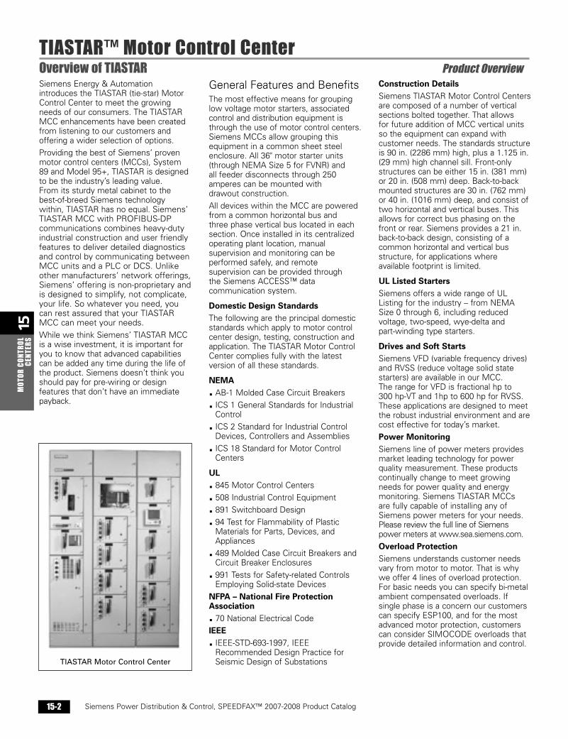
15 MOTOR CONTROL CENTERS TIASTAR™ Motor Control Center Overview of TIASTAR Product Overview Siemens Power Distribution & Control, SPEEDFAX™ 2007-2008 Product Catalog 15-2 Siemens Energy & Automation introduces the TIASTAR (tie-star) Motor Control Center to meet the growing needs of our consumers. The TIASTAR MCC enhancements have been created from listening to our customers and offering a wider selection of options. Providing the best of Siemens’ proven motor control centers (MCCs), System 89 and Model 95+, TIASTAR is designed to be the industry’s leading value. From its sturdy metal cabinet to the best-of-breed Siemens technology within, TIASTAR has no equal. Siemens’ TIASTAR MCC with PROFIBUS-DP communications combines heavy-duty industrial construction and user friendly features to deliver detailed diagnostics and control by communicating between MCC units and a PLC or DCS. Unlike other manufacturers’ network offerings, Siemens’ offering is non-proprietary and is designed to simplify, not complicate, your life. So whatever you need, you can rest assured that your TIASTAR MCC can meet your needs. While we think Siemens’ TIASTAR MCC is a wise investment, it is important for you to know that advanced capabilities can be added any time during the life of the product. Siemens doesn’t think you should pay for pre-wiring or design features that don’t have an immediate payback. General Features and Benefits The most effective means for grouping low voltage motor starters, associated control and distribution equipment is through the use of motor control centers. Siemens MCCs allow grouping this equipment in a common sheet steel enclosure. All 36" motor starter units (through NEMA Size 5 for FVNR) and all feeder disconnects through 250 amperes can be mounted with drawout construction. All devices within the MCC are powered from a common horizontal bus and three phase vertical bus located in each section. Once installed in its centralized operating plant location, manual supervision and monitoring can be performed safely, and remote supervision can be provided through the Siemens ACCESS™ data communication system. Domestic Design Standards The following are the principal domestic standards which apply to motor control center design, testing, construction and application. The TIASTAR Motor Control Center complies fully with the latest version of all these standards. NEMA AB-1 Molded Case Circuit Breakers ICS 1 General Standards for Industrial Control ICS 2 Standard for Industrial Control Devices, Controllers and Assemblies ICS 18 Standard for Motor Control Centers UL 845 Motor Control Centers 508 Industrial Control Equipment 891 Switchboard Design 94 Test for Flammability of Plastic Materials for Parts, Devices, and Appliances 489 Molded Case Circuit Breakers and Circuit Breaker Enclosures 991 Tests for Safety-related Controls Employing Solid-state Devices NFPA – National Fire Protection Association 70 National Electrical Code IEEE IEEE-STD-693-1997, IEEE Recommended Design Practice for Seismic Design of Substations Construction Details Siemens TIASTAR Motor Control Centers are composed of a number of vertical sections bolted together. That allows for future addition of MCC vertical units so the equipment can expand with customer needs. The standards structure is 90 in. (2286 mm) high, plus a 1.125 in. (29 mm) high channel sill. Front-only structures can be either 15 in. (381 mm) or 20 in. (508 mm) deep. Back-to-back mounted structures are 30 in. (762 mm) or 40 in. (1016 mm) deep, and consist of two horizontal and vertical buses. This allows for correct bus phasing on the front or rear. Siemens provides a 21 in. back-to-back design, consisting of a common horizontal and vertical bus structure, for applications where available footprint is limited. UL Listed Starters Siemens offers a wide range of UL Listing for the industry – from NEMA Size 0 through 6, including reduced voltage, two-speed, wye-delta and part-winding type starters. Drives and Soft Starts Siemens VFD (variable frequency drives) and RVSS (reduce voltage solid state starters) are available in our MCC. The range for VFD is fractional hp to 300 hp-VT and 1hp to 600 hp for RVSS. These applications are designed to meet the robust industrial environment and are cost effective for today’s market. Power Monitoring Siemens line of power meters provides market leading technology for power quality measurement. These products continually change to meet growing needs for power quality and energy monitoring. Siemens TIASTAR MCCs are fully capable of installing any of Siemens power meters for your needs. Please review the full line of Siemens power meters at www.sea.siemens.com. Overload Protection Siemens understands customer needs vary from motor to motor. That is why we offer 4 lines of overload protection. For basic needs you can specify bi-metal ambient compensated overloads. If single phase is a concern our customers can specify ESP100, and for the most advanced motor protection, customers can consider SIMOCODE overloads that provide detailed information and control. TIASTAR Motor Control Center
Transcript of TIASTAR™ Motor Control Center · MCC units and a PLC or DCS. Unlike other manufacturers’...
15M
OTOR
CON
TROL
CENT
ERS
Siemens / Speedfax Previous folio: 15-2
TIASTAR™ Motor Control CenterOverview of TIASTAR Product Overview
Siemens Power Distribution & Control, SPEEDFAX™ 2007-2008 Product Catalog15-2
Siemens Energy & Automationintroduces the TIASTAR (tie-star) MotorControl Center to meet the growingneeds of our consumers. The TIASTARMCC enhancements have been createdfrom listening to our customers andoffering a wider selection of options.
Providing the best of Siemens’ provenmotor control centers (MCCs), System89 and Model 95+, TIASTAR is designedto be the industry’s leading value. From its sturdy metal cabinet to the best-of-breed Siemens technologywithin, TIASTAR has no equal. Siemens’TIASTAR MCC with PROFIBUS-DPcommunications combines heavy-dutyindustrial construction and user friendlyfeatures to deliver detailed diagnosticsand control by communicating betweenMCC units and a PLC or DCS. Unlikeother manufacturers’ network offerings,Siemens’ offering is non-proprietary andis designed to simplify, not complicate,your life. So whatever you need, youcan rest assured that your TIASTARMCC can meet your needs.
While we think Siemens’ TIASTAR MCCis a wise investment, it is important foryou to know that advanced capabilitiescan be added any time during the life ofthe product. Siemens doesn’t think youshould pay for pre-wiring or designfeatures that don’t have an immediatepayback.
General Features and Benefits The most effective means for groupinglow voltage motor starters, associatedcontrol and distribution equipment isthrough the use of motor control centers.Siemens MCCs allow grouping thisequipment in a common sheet steelenclosure. All 36" motor starter units(through NEMA Size 5 for FVNR) and all feeder disconnects through 250amperes can be mounted with drawout construction.
All devices within the MCC are poweredfrom a common horizontal bus and three phase vertical bus located in eachsection. Once installed in its centralizedoperating plant location, manualsupervision and monitoring can beperformed safely, and remotesupervision can be provided through the Siemens ACCESS™ datacommunication system.
Domestic Design StandardsThe following are the principal domesticstandards which apply to motor controlcenter design, testing, construction andapplication. The TIASTAR Motor ControlCenter complies fully with the latestversion of all these standards.
NEMAAB-1 Molded Case Circuit Breakers
ICS 1 General Standards for IndustrialControl
ICS 2 Standard for Industrial ControlDevices, Controllers and Assemblies
ICS 18 Standard for Motor ControlCenters
UL845 Motor Control Centers
508 Industrial Control Equipment
891 Switchboard Design
94 Test for Flammability of PlasticMaterials for Parts, Devices, andAppliances
489 Molded Case Circuit Breakers andCircuit Breaker Enclosures
991 Tests for Safety-related ControlsEmploying Solid-state Devices
NFPA – National Fire ProtectionAssociation
70 National Electrical Code
IEEEIEEE-STD-693-1997, IEEERecommended Design Practice forSeismic Design of Substations
Construction DetailsSiemens TIASTAR Motor Control Centersare composed of a number of verticalsections bolted together. That allows for future addition of MCC vertical unitsso the equipment can expand withcustomer needs. The standards structureis 90 in. (2286 mm) high, plus a 1.125 in.(29 mm) high channel sill. Front-onlystructures can be either 15 in. (381 mm)or 20 in. (508 mm) deep. Back-to-backmounted structures are 30 in. (762 mm)or 40 in. (1016 mm) deep, and consist oftwo horizontal and vertical buses. Thisallows for correct bus phasing on thefront or rear. Siemens provides a 21 in.back-to-back design, consisting of acommon horizontal and vertical busstructure, for applications where available footprint is limited.
UL Listed StartersSiemens offers a wide range of ULListing for the industry – from NEMASize 0 through 6, including reducedvoltage, two-speed, wye-delta and part-winding type starters.
Drives and Soft StartsSiemens VFD (variable frequency drives)and RVSS (reduce voltage solid statestarters) are available in our MCC. The range for VFD is fractional hp to 300 hp-VT and 1hp to 600 hp for RVSS.These applications are designed to meetthe robust industrial environment and arecost effective for today’s market.
Power MonitoringSiemens line of power meters providesmarket leading technology for powerquality measurement. These productscontinually change to meet growingneeds for power quality and energymonitoring. Siemens TIASTAR MCCsare fully capable of installing any ofSiemens power meters for your needs.Please review the full line of Siemenspower meters at www.sea.siemens.com.
Overload ProtectionSiemens understands customer needsvary from motor to motor. That is whywe offer 4 lines of overload protection.For basic needs you can specify bi-metalambient compensated overloads. Ifsingle phase is a concern our customerscan specify ESP100, and for the mostadvanced motor protection, customerscan consider SIMOCODE overloads thatprovide detailed information and control.
TIASTAR Motor Control Center
Sect_15_Speedfax2007 12/5/06 9:58 AM Page 15-2

15M
OTOR CONTROLCENTERS
Siemens / Speedfax Previous folio: 15-3
TIASTAR™ Motor Control CenterProduct Overview
Siemens Power Distribution & Control, SPEEDFAX™ 2007-2008 Product Catalog 15-3
ESP100 Solid State OverloadsESP100 solid state overload relays areself powered, requiring no separate120V source to power the circuit board.They provide phase loss protection,fewer connection points and high repeattrip accuracy which results in longermotor life and cost savings. NEMAClass 10, 20 and 30 trip curves areavailable for a variety of applications.
The ESP100 solid state overloadprovides phase loss protection for themotor by tripping within three secondsupon complete loss of one phase of athree phase motor branch circuit.
Each overload has at least a 2:1 currentadjustment range with the adjustmentdial reading out in full load amps. Inaddition to the markings on the dialthere are audible clicks which allow for extremely fine tuning.
The heaterless construction of theseoverloads minimizes energy costs andthe costs of cabinet ventilation orcooling. Solid state overloads can beused at temperatures from –30°C to�70°C and are rated for 50Hz and 60Hzapplications.
ESP100 panel mounted overloads can beused to upgrade existing starterapplications where panel mountedthermal overloads are used. In addition,ESP100 overloads can be panel mountedwhen used with other types ofcontrollers, such as DP, IEC contactors,and soft starts.
ESP100 overloads can be used on highvoltage applications, making them idealfor use with vacuum contactors andother high voltage control.
ESP100 overloads can be retrofitted on existing contactors using the retrofitplate suffixes or on other brands usingthe plates listed in the competitiveretrofit plates table on page 16-48.
SIMOCODE ProSIMOCODE Pro is the latest generationof Motor Management System (“Smart Overload”) bringing a new levelof flexibility and functionality within theSiemens smart motor control center. By means of a PROFIBUS DP interface, it can easily be linked to higher-levelautomation systems. SIMOCODE Proimplements all motor protection andcontrol functions, determines operational,diagnostic and statistical data andorganizes the communication betweenthe automation system and MCC bucket.
The SIMOCODE Pro consists of twodevice series with different levels offunctionality:
SIMOCODE Pro C (Compact)The compact motor management systemcan be used for Full Voltage Non-reversing (FVNR) starters, Full VoltageReversing (FVR) starters, and baseoverload functionality.
SIMOCODE Pro V (Variable)The variable motor management systemhas an even greater range of functions,including voltage and power monitoringand expandable modules for additionalI/O, as well as temperature and groundfault protection.
Note: For detailed information on the SIMODE Pro pleasecontact the local Siemens Sales Office.
Thermal Overloads Bimetal Ambient CompensatedBimetal ambient compensated overloadrelays protect both the motor andequipment by opening the control circuitwhen the motor experiences an overloadcondition. The bimetal overload relay maybe set for either manual or automaticreset and can be supplied with standardClass 20 heater elements or optionalClass 10 heater elements as required. An ambient compensated model of thebimetal overload is available.
Bimetal Ambient Compensated Overload
ESP100 Solid State Overload
CT Module
Keypad (Door Mounted)
SIMOCODE Pro C
Expandable Module
CT Module
Keypad (Door Mounted)
SIMOCODE Pro V
Sect_15_Speedfax2007 5/8/07 4:36 PM Page 15-3
15M
OTOR
CON
TROL
CENT
ERS
Siemens / Speedfax Previous folio: 15-4
Motor Control CentersProduct Overview
Siemens Power Distribution & Control, SPEEDFAX™ 2007-2008 Product Catalog15-4
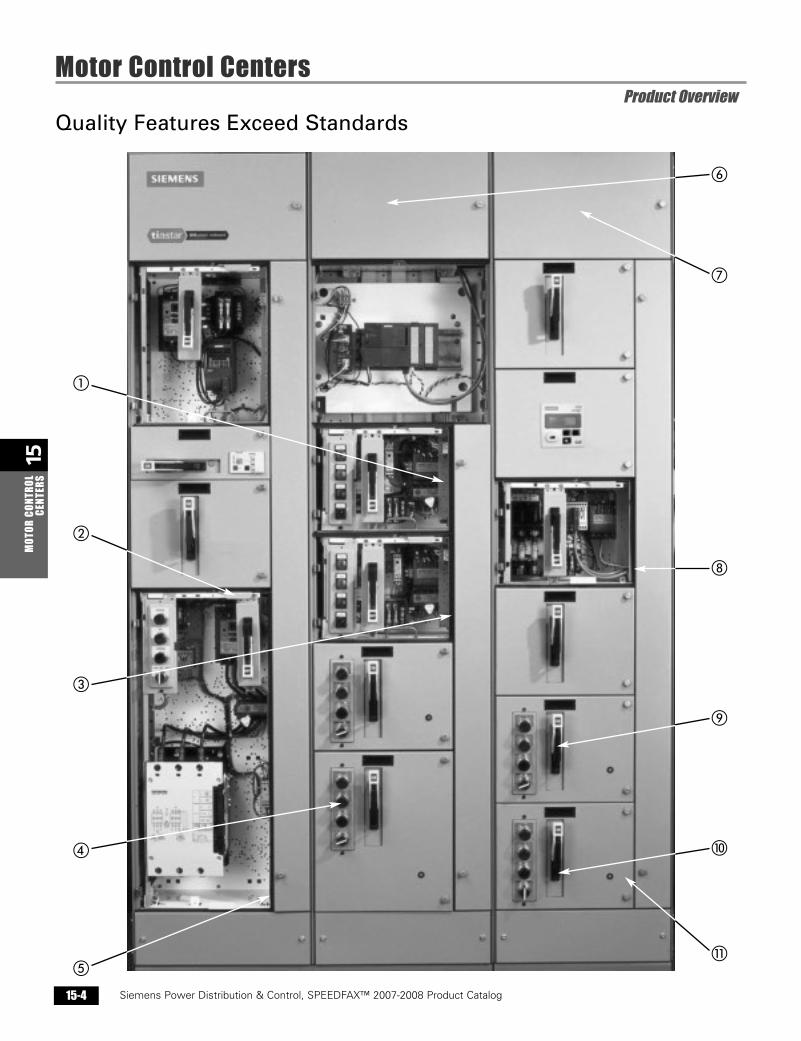
Quality Features Exceed Standards
�
�
�
�
�
�
�
�
�
Sect_15_Speedfax2007 11/28/06 2:07 PM Page 15-4
15M
OTOR CONTROLCENTERS
Siemens / Speedfax Previous folio: 15-5
Motor Control CentersProduct Overview
Siemens Power Distribution & Control, SPEEDFAX™ 2007-2008 Product Catalog 15-5
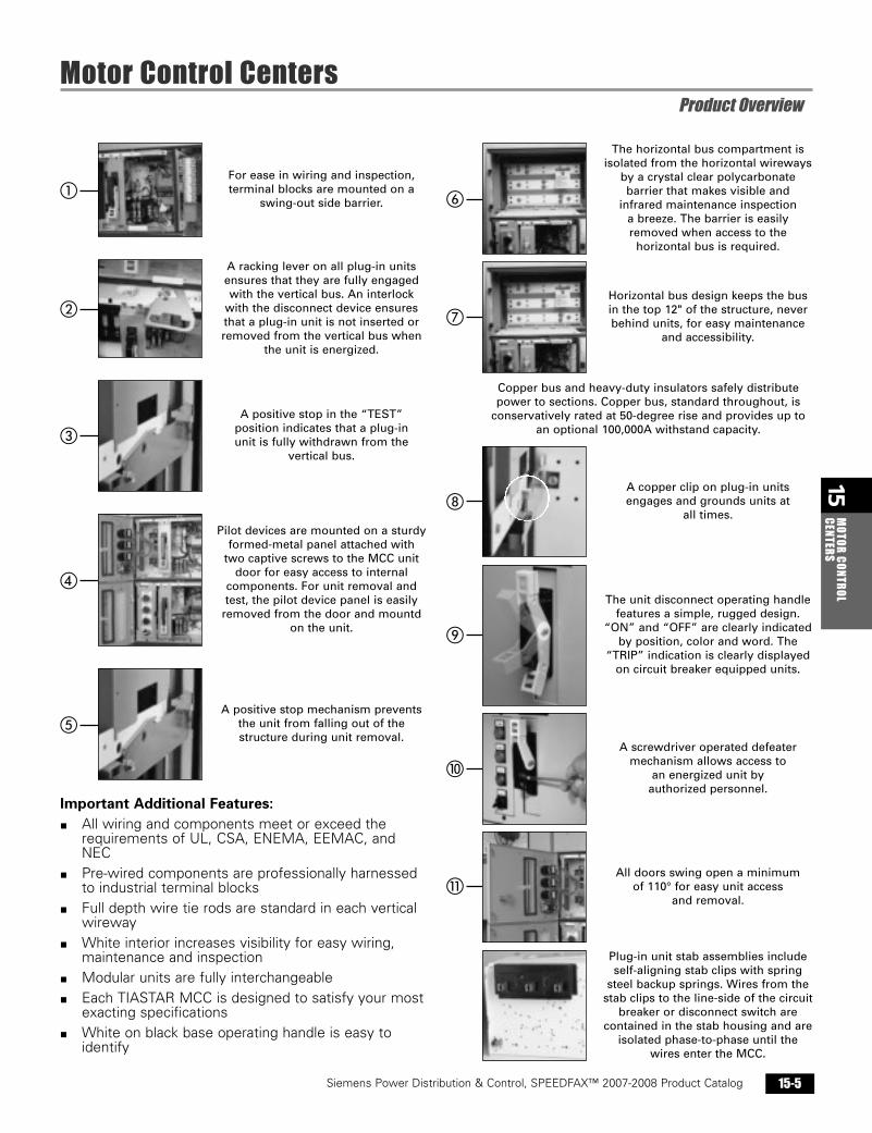
For ease in wiring and inspection,
terminal blocks are mounted on a
swing-out side barrier.
A racking lever on all plug-in units
ensures that they are fully engaged
with the vertical bus. An interlock
with the disconnect device ensures
that a plug-in unit is not inserted or
removed from the vertical bus when
the unit is energized.
A positive stop in the “TEST”
position indicates that a plug-in
unit is fully withdrawn from the
vertical bus.
Pilot devices are mounted on a sturdy
formed-metal panel attached with
two captive screws to the MCC unit
door for easy access to internal
components. For unit removal and
test, the pilot device panel is easily
removed from the door and mountd
on the unit.
A positive stop mechanism prevents
the unit from falling out of the
structure during unit removal.
Important Additional Features:� All wiring and components meet or exceed the
requirements of UL, CSA, ENEMA, EEMAC, andNEC
� Pre-wired components are professionally harnessedto industrial terminal blocks
� Full depth wire tie rods are standard in each verticalwireway
� White interior increases visibility for easy wiring,maintenance and inspection
� Modular units are fully interchangeable� Each TIASTAR MCC is designed to satisfy your most
exacting specifications� White on black base operating handle is easy to
identify
The horizontal bus compartment is
isolated from the horizontal wireways
by a crystal clear polycarbonate
barrier that makes visible and
infrared maintenance inspection
a breeze. The barrier is easily
removed when access to the
horizontal bus is required.
Horizontal bus design keeps the bus
in the top 12" of the structure, never
behind units, for easy maintenance
and accessibility.
Copper bus and heavy-duty insulators safely distribute
power to sections. Copper bus, standard throughout, is
conservatively rated at 50-degree rise and provides up to
an optional 100,000A withstand capacity.
A copper clip on plug-in units
engages and grounds units at
all times.
The unit disconnect operating handle
features a simple, rugged design.
“ON” and “OFF” are clearly indicated
by position, color and word. The
“TRIP” indication is clearly displayed
on circuit breaker equipped units.
A screwdriver operated defeater
mechanism allows access to
an energized unit by
authorized personnel.
All doors swing open a minimum
of 110° for easy unit access
and removal.
Plug-in unit stab assemblies include
self-aligning stab clips with spring
steel backup springs. Wires from the
stab clips to the line-side of the circuit
breaker or disconnect switch are
contained in the stab housing and are
isolated phase-to-phase until the
wires enter the MCC.
�
�
�
�
�
�
�
�
�
Sect_15_Speedfax2007 11/28/06 2:07 PM Page 15-5

15M
OTOR
CON
TROL
CENT
ERS
Siemens Power Distribution & Control, SPEEDFAX™ 2007-2008 Product Catalog15-6
Siemens / Speedfax Previous folio: 15-6
TIASTAR™ Motor Control CentersTechnical / Dimensions
DimensionsHeight: 91.125 in. (2318 mm)(Front Mounted Only Structure)Width: 20 in. (508 mm)
24 in. (610 mm)30 in. (762 mm)
Depth: Standard: 15 in. (381 mm)Optional: 20 in. (508 mm)Optional:* 31 or 41 in.
(762 or 1016 mm)*(Front mtd. only structures mtd. Back-to-Back)
(Back-to-Back structure)Width: 20 in. (508 mm)
30 in. (762 mm)Depth: 21 in. (533 mm)
Vertical Wireway Height:72 in. (1829 mm)
Width: 4 in. (127 mm)Depth: 10 in. (203 mm)Cross Section: 38.25 square in.
(972 square mm)Top Horizontal WirewayFront Mounted Only and Back-to-Back Mounted
Height: 12 in. (305 mm)Depth: 7 in. (178 mm)
Bottom Horizontal WirewayFront Mounted Only
Height: 6 in. (152 mm)Depth: 15 in. (381 mm)
20 in. (508 mm)or Back-to-Back Mounted
Height: 6 in. (152 mm)Depth: 30 or 40 in.
(762 or 1016 mm)
Structural Gauge ChartStructural PartsDivider Sheets . . . . . . . . . . . . . . . . . . . . . . . . .14 ga.Side Sheets . . . . . . . . . . . . . . . . . . . . . . . . . . .14 ga.Center Bottom Cross Ties . . . . . . . . . . . . . . . .12 ga.Rear-Channel
(Front Mounting only) . . . . . . . . . . . . . . .13 ga.Channel Sills . . . . . . . . . . . . . . . . . . . . . . . . . . .7 ga.Center-Top Channel . . . . . . . . . . . . . . . . . . . . .13 ga.Vertical Bus Mounting Angles . . . . . . . . . . . . .14 ga.Lifting Angles . . . . . . . . . . . . . . . . . . . . . . . . . .7 ga.Rear Covers . . . . . . . . . . . . . . . . . . . . . . . . . . .16 ga.Top Plates . . . . . . . . . . . . . . . . . . . . . . . . . . . .13 ga.End Covers . . . . . . . . . . . . . . . . . . . . . . . . . . .16 ga.Separator Angles . . . . . . . . . . . . . . . . . . . . . . .12 ga.Shelf Brackets . . . . . . . . . . . . . . . . . . . . . . . . .10 ga.
Unit PartsTop and Bottom Unit Barriers . . . . . . . . . . . . .14 ga.Back Pan . . . . . . . . . . . . . . . . . . . . . . . . . .13, 14 ga.Side Barrier Plate . . . . . . . . . . . . . . . . . . . . . . .18 ga.Angles . . . . . . . . . . . . . . . . . . . . . . . . . . . . . . .14 ga.Doors . . . . . . . . . . . . . . . . . . . . . . . . . . . . .13, 14 ga.
Finish (Ext.) ANSI 61 Light GrayElectrostatically applied dry powder paintis standard.
PlatingAll power bus, copper tin-plated as std.Silver plating available by request.
Horizontal BusAmpere Ratings
Standard: 600A, tin-plated CuOptional: 800A, Cu
1200A, Cu1600A, Cu2000A, Cu2500A, Cu
Vertical BusAmpere Ratings
Standard: 300A, tin-platedOptional: 600A, Cu
Neutral Bus (Bottom Mounted)Optional: Full neutral CuOptional: Neutral landing padRatings: 600A to 1600A
Bus BracingStandard: 42,000A,Optional: 65,000A, and
100,000A Sym.
Incoming Line TerminationsIncoming line arrangements areavailable in many configurations from 600A to 2500A.
BarriersStandard:Isolation Barrier: Grounded sheet
steel with stabopenings.
Standard: Inserts to cover unusedopenings in V-bus barrier.
Optional: Automatic shuttermechanism.
Ground Bus (Bottom Mounted)Required for UL labeling
Standard: .25 in. x 1 in. unplated Cu.Optional ground bus available up to1200A.Vertical ground bus available asoption, rating 300A.Also available with motor groundterminations.
Weight Table
Wiring SpecificationsControl on Units
16 gauge19 strand bonded copper105°C – 600V
Interconnection Control Wiring Between Units
14 gauge19 strand copper105°C – 600V
Power Wiring – Sized to suit maximum HP rating of unit
12 gauge to 2 gauge19 strand copper105°C – 600V
1 gauge to 500 MCM19 strand to 37 strand copper105°C – 600V
Enclosure TypesNEMA 1 (Standard) – IndoorNEMA 1A Gasketed – IndoorNEMA 2 – Drip-proof – IndoorNEMA 12 – Dust tight – IndoorNEMA 3R – Rainproof – Outdoor
(Non-walk-in)
MCC Shutter MechanismAutomatic shutter mechanisms whenspecified will be supplied at the stab in location of each plug-in unit andrequested future space. Unused stabopenings will be covered with snap-inhole plugs.
Pull Box (Top Hat)Available in 12 in., 18 in. or 24 in. high; 20 in. or 30 in. wide; 15 in. or 20 in. deep.
Dimensions Shippinginches (mm) Weight
per SectionH W D Type in lbs. (kg)
20 15 550 lbs. (250)(508) (381) front only20 20 600 lbs. (273)
(508) (508)91.13 20 30 back-to-back 850 lbs. (386)(2315) (508) (762)
30 20 front only 800 lbs. (364)(762) (508)20 21 back-to-back 900 lbs. (409)
(508) (533)
Sect_15_Speedfax2007 11/28/06 2:07 PM Page 15-6
15M
OTOR CONTROLCENTERS
Siemens Power Distribution & Control, SPEEDFAX™ 2007-2008 Product Catalog 15-7
Siemens / Speedfax Previous folio: 15-7
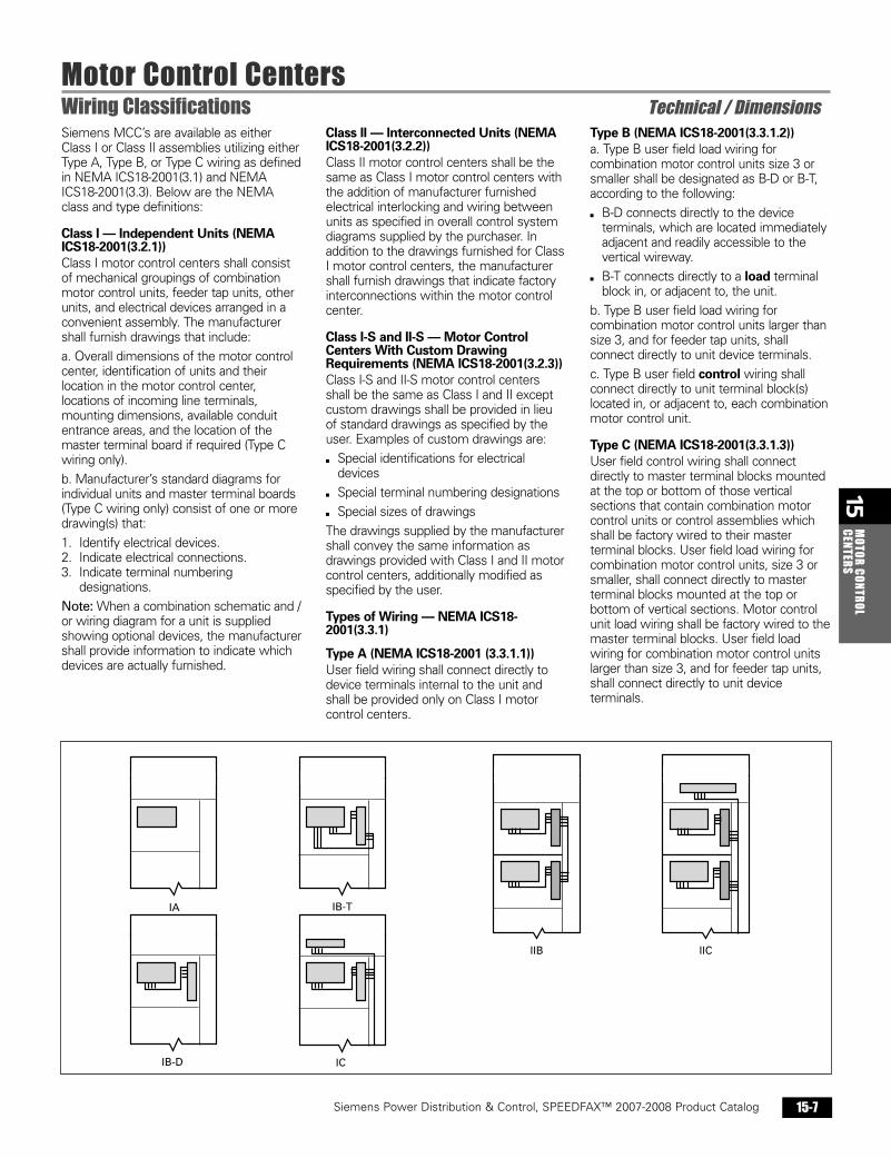
Motor Control CentersWiring Classifications Technical / DimensionsSiemens MCC’s are available as eitherClass I or Class II assemblies utilizing eitherType A, Type B, or Type C wiring as definedin NEMA ICS18-2001(3.1) and NEMAICS18-2001(3.3). Below are the NEMAclass and type definitions:
Class I — Independent Units (NEMA ICS18-2001(3.2.1))Class I motor control centers shall consistof mechanical groupings of combinationmotor control units, feeder tap units, otherunits, and electrical devices arranged in aconvenient assembly. The manufacturershall furnish drawings that include:
a. Overall dimensions of the motor controlcenter, identification of units and theirlocation in the motor control center,locations of incoming line terminals,mounting dimensions, available conduitentrance areas, and the location of themaster terminal board if required (Type Cwiring only).
b. Manufacturer’s standard diagrams forindividual units and master terminal boards(Type C wiring only) consist of one or moredrawing(s) that:
1. Identify electrical devices.2. Indicate electrical connections.3. Indicate terminal numbering
designations.
Note: When a combination schematic and /or wiring diagram for a unit is suppliedshowing optional devices, the manufacturershall provide information to indicate whichdevices are actually furnished.
Class II — Interconnected Units (NEMAICS18-2001(3.2.2))Class II motor control centers shall be thesame as Class I motor control centers withthe addition of manufacturer furnishedelectrical interlocking and wiring betweenunits as specified in overall control systemdiagrams supplied by the purchaser. Inaddition to the drawings furnished for ClassI motor control centers, the manufacturershall furnish drawings that indicate factoryinterconnections within the motor controlcenter.
Class I-S and II-S — Motor ControlCenters With Custom DrawingRequirements (NEMA ICS18-2001(3.2.3)) Class I-S and II-S motor control centersshall be the same as Class I and II exceptcustom drawings shall be provided in lieuof standard drawings as specified by theuser. Examples of custom drawings are:
▪ Special identifications for electricaldevices
▪ Special terminal numbering designations
▪ Special sizes of drawings
The drawings supplied by the manufacturershall convey the same information asdrawings provided with Class I and II motorcontrol centers, additionally modified asspecified by the user.
Types of Wiring — NEMA ICS18-2001(3.3.1)
Type A (NEMA ICS18-2001 (3.3.1.1)) User field wiring shall connect directly todevice terminals internal to the unit andshall be provided only on Class I motorcontrol centers.
Type B (NEMA ICS18-2001(3.3.1.2)) a. Type B user field load wiring forcombination motor control units size 3 orsmaller shall be designated as B-D or B-T,according to the following:
▪ B-D connects directly to the deviceterminals, which are located immediatelyadjacent and readily accessible to thevertical wireway.
▪ B-T connects directly to a load terminalblock in, or adjacent to, the unit.
b. Type B user field load wiring forcombination motor control units larger thansize 3, and for feeder tap units, shallconnect directly to unit device terminals.
c. Type B user field control wiring shallconnect directly to unit terminal block(s)located in, or adjacent to, each combinationmotor control unit.
Type C (NEMA ICS18-2001(3.3.1.3))User field control wiring shall connectdirectly to master terminal blocks mountedat the top or bottom of those verticalsections that contain combination motorcontrol units or control assemblies whichshall be factory wired to their masterterminal blocks. User field load wiring forcombination motor control units, size 3 orsmaller, shall connect directly to masterterminal blocks mounted at the top orbottom of vertical sections. Motor controlunit load wiring shall be factory wired to themaster terminal blocks. User field loadwiring for combination motor control unitslarger than size 3, and for feeder tap units,shall connect directly to unit deviceterminals.
IC
IB-T
IB-D
IA
IIB IIC
Sect_15_Speedfax2007 12/5/06 9:50 AM Page 15-7
15M
OTOR
CON
TROL
CENT
ERS
Siemens Power Distribution & Control, SPEEDFAX™ 2007-2008 Product Catalog15-8
Siemens / Speedfax Previous folio: 15-8
Motor Control CentersStarter Ratings and Dimensions Technical / Dimensions
MaximumHorsepower Rating
0-1
208 V 230 V 460 V
Full Voltage — UL Listed FVNR FVR IR Std./Opt.— FVNR FVR IR—
ND6 N/A N/A
LD6-ETI
JD6-ETI
FD6-ETI
MCP7.5
2 103 254 40
5 75
6� 150
7.5153050
100
200
300
10 12 (305) 18 (457)12 (305) 24 (610)
42 / 100
100
42 / 100
42 / 100
18 (457) 30 (762)
30 / 30 12 (305) 60 / 60 12 (305) 100 / 100 24 (610)FD6MCS / 200
JD6MCS / 400
MD6MCS / 600
ND6MCS / 1200
72 (1829) � 72 (1829) �30W (762W) �
42 (1067)
18 (457)24 (610)36 (914)48 (1219) �24 (610)
48 (1219) 72 (1829)30W (762W)
72 (1829)30W (762W)72 (1829)
72 (1829)40W × 20D(1016W × 508D)
72 (1829)30W × 20D(762W × 508D)
36 (914)
36 (914) 72 (1829)�
2550
100
200
400
6007� —
2�
RVAT � IR Std./Opt.— RVAT � IR—
ND6
LD6-ETI
JD6-ETIFD6-ETI
MCP10
3� 254� 405� 75
6� 150
300
153050
100
200
300
25 42 (1067)42 (1067)
100
48 (1219)72 (1829), 30W (762W)
60 / 60 42 (1067)100 / 100 48 (1219)FD6MCS / 200 60 (1524) JD6MCS / 400
MD6MCS / 800
ND6MCS / 1200
72 (1829)
42 / 100
42 / 100
42 / 100
72 (1829)30W (762W)
72 (1829)30W (762W)
72 (1829)50W × 20D(1270W × 508D)
72 (1829)50W × 20D(1270W × 508D)
50100200
400
6007�
0-1
Two Speed, ConstantOr Variable Torque — UL Listed 2S2W 2S1W IR Std./Opt.— 2S2W 2SW1 IR—
LD6-ETI
JD6-ETI
FD6-ETI
MCP7.5
2 103 254 40
5� 75
6� 150
7.5153050
100
200
10 24 (610) 24 (610)24 (610) 24 (610)
42 / 100
100
42 / 100
42 / 100
30 (762) 36 (914)
30 / 30 24 (610)60 / 60 24 (610)100 / 100 36 (914)FD6MCS / 200
JD6MCS / 400
MD6MCS / 600
48 (1219)
24 (610)24 (610)48 (1219)60 (1524) �36 (914)
72 (1829)30W (762W)72 (1829)30W (762W)
ConsultSiemens
ConsultSiemens
72 (1829)40W (1016W)
48 (1219)
2550
100
200
400
0-1
Two Speed, ConstantHorsepower — UL Listed
Reduced Voltage AutotransformerNon-Reversing, Closed Transition— UL Listed
1RVPW IR Std./Opt.— RVPW IR—
MD6
LD6-ETI
JD6-ETI
MCP10
2 203 404� 75
5� 125
—
10255075
150
250
1524 (610)
100
36 (914)36 (914)
60 / 60 24 (610)100 / 100FD6MCS / 200JD6MCS / 400
48 (1219)
LD6MCS / 600
MD6MCS / 600
72 (1829) �
42 / 100
42 / 100
42 / 100
72 (1829)30W (762W)
72 (1829)30W (762W)
72 (1829)30W (762W)
4075
150
350
5006�
Two Step Part Winding,Star Connected � — UL Listed
2S2W-CH 2S1W-CH IR Std./Opt.— 2S2W-CH 2SW1-CH IR—
LD6-ETI
JD6-ETI
FD6-ETI
MCP7.5
2 103 254� 40
5� 75
6� 150
7.5153050
100
200
10 24 (610) 24 (610)24 (610) 24 (610)
42 / 100
100
42 / 100
42 / 100
30 (762) 36 (914)
30 / 30 24 (610)60 / 60 24 (610)100 / 100 36 (914)FD6MCS / 200
JD6MCS / 400
MD6MCS / 600
72 (1829)
48 (1219)
24 (610)24 (610)48 (1219)60 (1524) � 30 (762)
ConsultSiemens
ConsultSiemens
72 (1829)40W (1016W)
48 (1219)
2550
100
200
400
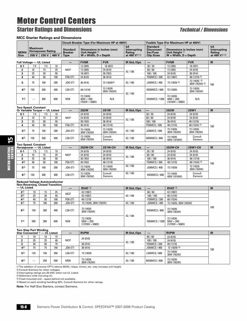
Circuit Breaker Type (For Maximum HP at 460V) Fusible Type (For Maximum HP at 460V)
NEMASize
StandardBreakerType
Dimensions in Inches (mm)Unit Height �W = Width, D = Depth
Dimensions in Inches (mm)Unit Height �W = Width, D = Depth
StandardDisconnectSw/FuseClip Sizes
kAInterruptingRatingat 480 V� �
kAInterruptingRatingat 480 V� �
MCC Starter Ratings and Dimensions
�
�
The addition of oversize CPT’s (above 50VA), relays, timers, etc. may increase unit height.Consult Siemens for other voltages.
� Interrupting ratings are 25 kAIC when not UL Listed.� Stationary units (not plug-in).� Fixed mounted unit – space behind not available.� Based on each winding handling 50%. Consult Siemens for other ratings.
72 (1829)30W (762W)
72 (1829)30W (762W)
72 (1829)30W (762W)
72 (1829)30W (762W)
72 (1829)30W (762W)
72 (1829)30W (762W)
72 (1829)30W (762W)
72 (1829), 30W (762W)
24 (610)
Note: For Half Size Starters, contact Siemens.
Sect_15_Speedfax2007 11/28/06 2:07 PM Page 15-8

15M
OTOR CONTROLCENTERS
Siemens Power Distribution & Control, SPEEDFAX™ 2007-2008 Product Catalog 15-9
Siemens / Speedfax Previous folio: 15-9
Motor Control CentersStarter Ratings and Dimensions Technical / Dimensions
RatingHP �
2
5 24 (610)(Plug-in)
36 (914)(Plug-in)
60 (1524)(Recessed Panel,Fixed Mounted)
20 (508) × 15 (381)
50 (1270) × 20 (508)20 (508) × 20 (508)
48 (1219)(Plug-in)
MM440 4
20 MM440 32
40 MM440 52
60MM440
240 Max.
150-300 MM440 370 Max.
7.5 MM440 11MM440 7.6MM440 8.5
10MM440 19MM440 14
15MM440 25MM440 23
25MM440 34MM440 34
30MM440 46MM440 45
50MM440MM440 75
Dimensions—In. (mm) ��
480V� Variable Frequency Drives — NEMA 1A MCC Enclosures �
MountingHeight
StructureW × D
DriveType
RatedAmperes
� For other available voltage ratings, consult Siemens.� For other enclosure types, consult Siemens.� Ratings are for variable torque applications. Consult Siemens for other applications.� Dimensions shown are for circuit breaker or fusible disconnects.� Drives with bypass and / or isolation require extra mounting space. Consult Siemens for further information.
18 (457) (Plug-in)
75-125 185 Max. 72 (1829)(Recessed Panel, Fixed-Mounted)
MaximumHorsepower Rating208 V 230 V 460 V
2
Reduced Voltage Wye Delta,Open and Closed Transition YDO YDC IR Std./Opt.— IR
MCPMCPFD6-ETI
203 254 60
253060
40 30 (762) 42 (1067)30 (762) 42 (1067)
42 / 10042 / 10042 / 100
10036 (914) 48 (1219)
100 / 100 36 (914)
400MCS / 40048 (1219)72 (1829) �
48 (1219)60 (1524)72 (1829) �
60125
LD6-ETI5� 150 150 600MCS-60072 (1829) �30W (762W)
72 (1829) �30W (762W) 42 / 100300
1
Solid State Reduced VoltgageOpen and Closed Transition � IR Std./Opt.— � IR—
CLD6-ETI
CJD6-ETI
CFD6-ETI
CED6-ETI
CED6-ETI
CED6-ETI7.52 10
3 25
4 40
5 75
6 150
7.515
30
50
100
150
10 18 (457) �
36 (914) �
42 / 100 100
36 (914) �
(30 / 30) 18 (457) �
(60 / 60) 36 (914) �
(EDMCS / 100) 36 (914) �
(EDMCS / 100) 60 (1524)
(EDMCS / 100) 60 (1524) �
(EDMCS / 100) 72 (1829) � �
36 (914)
48 (1219) �
72 (1829) �
72 (1829) �30W (508W)
72 (1829) �30W (508W)
0-1
Compact Units — AvailableFVNR Only — UL Listed
CircuitBreaker Type Fusible Type IR Std./Opt.—
MCPED6-ETIED6-ETI
7.52 103 25
7.51530
1012 (305) � 18 (457) �
42 / 100
15 (381) � 30 (762) �2550
FD64 40 50 21 (533) � 30 (762) �100
25
50
100
200
350
Circuit Breaker Type (For Maximum HP at 460V) Fusible Type (For Maximum HP at 460V)
NEMASize
StandardBreakerType
Dimensions in Inches (mm)Unit Height �
W = Width, D = Depth
Dimensions in Inches (mm)Unit Height �W = Width, D = Depth
StandardDisconnectSw / FuseClip Sizes
kAInterruptingRatingat 480 V �
kAInterruptingRatingat 480 V�
MCC Starter Ratings and Dimensions (cont'd)
YDO YDC—
250MCS / 200
�
�
The addition of oversize CPT’s (above 50VA), relays, timers, etc. may increase unit height.Consult Siemens for other voltages.
� Stationary units — Not plug in.� Requires 30 in. (762 mm) wide structure.� Bypass and / or isolation requires additional space.� 15 HP at 230V requires additional unit space.
�
Consult Siemens.The addition of relays, timers, etc. will require additional space.
� Unit includes rated line side isolation starter and J fuses.
6 (152)� 6 (152)�
AmpRatingMain Lug Only
18 1 to 18 30 (762) 30 (762) 30 (762)225 30 1 to 30 36 (914) 36 (914) 36 (914)
42 1 to 42 42 (1067) 42 (1067) 42 (1067)
Height In Inches (mm)1Ø, 3W240/120
3Ø, 4W208Y/120
3Ø, 4W277/480
Lighting PanelboardsApplied in MCC’s
NumberOfCircuits Panel
Main Breaker18 1 to 18 30 (762) 30 (762) 30 (762)22530 1 to 30 36 (914) 36 (914) 36 (914)
25042 1 to 42 42 (1067) 42 (1067) 42 (1067)
3 � 18 (457)
37.5 24 (610) � �
24 (610)
915253045
� Transformer mounted on brackets 6 in. (152 mm) off sills.� Requires 20 in. (508 mm) deep structure.
kVARating
1
1
1.5Plate-Mounted in12 in. (305 mm) space2
357.5
10 18 (457) �
24 (610) � �
152530
Unit HeightIn Inches (mm)
Distribution Transformers
Phase
12 (305)
Sect_15_Speedfax2007 11/28/06 2:07 PM Page 15-9
15M
OTOR
CON
TROL
CENT
ERS
Siemens Power Distribution & Control, SPEEDFAX™ 2007-2008 Product Catalog15-10
Siemens / Speedfax Previous folio: 15-10
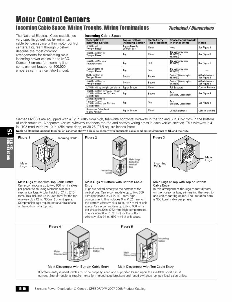
Motor Control CentersIncoming Cable Space, Wiring Troughs, Wiring Terminations Technical / DimensionsThe National Electrical Code establishesvery specific guidelines for minimumcable bending space within motor controlcenters. Figures 1 through 5 belowdescribe the most commonarrangements for terminating mainincoming power cables in the MCC.Consult Siemens for incoming linecompartment braced for 100,000amperes symmetrical, short circuit.
Siemens MCC’s are equipped with a 12 in. (305 mm) high, full-width horizontal wireway in the top and 6 in. (152 mm) in the bottomof each structure. A separate vertical wireway connects the top and bottom wiring areas in each vertical section. This wireway is 4in. (102 mm) wide by 10 in. (254 mm) deep, or 38.25 (972) square inches (mm).Note: All standard Siemens termination schemes shown herein do comply with applicable cable bending requirements of UL and the NEC.
MainLugs
Incoming CableFigure 1
Main Lugs at Top with Top Cable EntryCan accommodate up to two 600 kcmil cablesper phase when using Siemens standardmechanical lugs. A total height of 24 in. (610mm). This includes 12 in. (305 mm) for the topwireway plus 12 in. (305mm) of unit space.Compression lugs require extra vertical spaceor the addition of a top hat.
Main Lugs at Top with Top or BottomCable EntryIn this arrangement the lugs mount directlyon the horizontal bus, eliminating the need touse unit mounting space. The limitation hereis 350 kcmil cable per phase.
Main Lugs
Incoming Cable
Figure 4
Main Disconnect with Bottom Cable Entry Main Disconnect with Top Cable Entry
Top or Bottom Consult Siemens
Incoming Cable SpaceTop or BottomIncoming Section
Space Requirementsin Inches (mm) Notes
Description ofIncoming Service
Cable EntryTop or Bottom
≤ 350 kcmilTwo per Phase
Top — Directlyon Main Bus
Top Wireway plus12.0 (305) or18.0 (457)
Bottom Wireway plus24.0 (610)
Bottom Wireway plus18.0 (457)
Top Wireway plus24.0 (607)
Top
Top
Top Top
Top
Top Top SeeBreaker / Disconnect
SeeBreaker / Disconnect
Bottom Bottom
BottomBottom
Top or Bottom
350 kcmil One orTwo per Phase
≤ 600 kcmil One orTwo per Phase≤ 750 kcmil, up to eight per phase
Busway or Cable Feedto Line Reactor
750 kcmil One orTwo per Phase
≤ 600 kcmil One orTwo per Phase
≤ 600 kcmil Three orFour per Phase
≤ 500 kcmil One or Two per Phase≤ 750 kcmil One per Phase toMain Breaker≤ 500 kcmil One toFour per Phase≤ 750 kcmil One per Phase toMain Breaker
Either
Either
Top
Bottom
Either Consult Siemens
Consult Siemens
See Figure 4
See Figure 5
Full Structure
Either
None See Figure 3
See Figure 1
600 A MaximumSee Figure 2600 A MaximumSee Figure 2
Top Wireway plus18.0 (457)
—
See Figure 1
Figure 2
Figure 5
If bottom entry is used, cables must be properly laced and supported based upon the available short circuitcurrent. See dimensional requirements for molded case breakers and fused switches, consult local sales office.
Figure 3
Main Lugs at Bottom with Bottom CableEntryLugs are bolted directly to the bottom of thevertical bus. Can accommodate up to two 350kcmil per phase in 24 in. (610 mm) highcompartment. This includes 6 in. (152 mm) forthe bottom wireway plus 18 in. (457 mm) of unitspace. Can accommodate up to two 600 kcmilper phase in 30 in. (762 mm) high compartment.This includes 6 in. (152 mm) for the bottomwireway plus 24 in. (610 mm) of unit space.
Sect_15_Speedfax2007 11/28/06 2:07 PM Page 15-10
15M
OTOR CONTROLCENTERS
Siemens Power Distribution & Control, SPEEDFAX™ 2007-2008 Product Catalog 15-11
Siemens / Speedfax Previous folio: 15-11
Motor Control Center Replacement UnitsAftermarket Overview
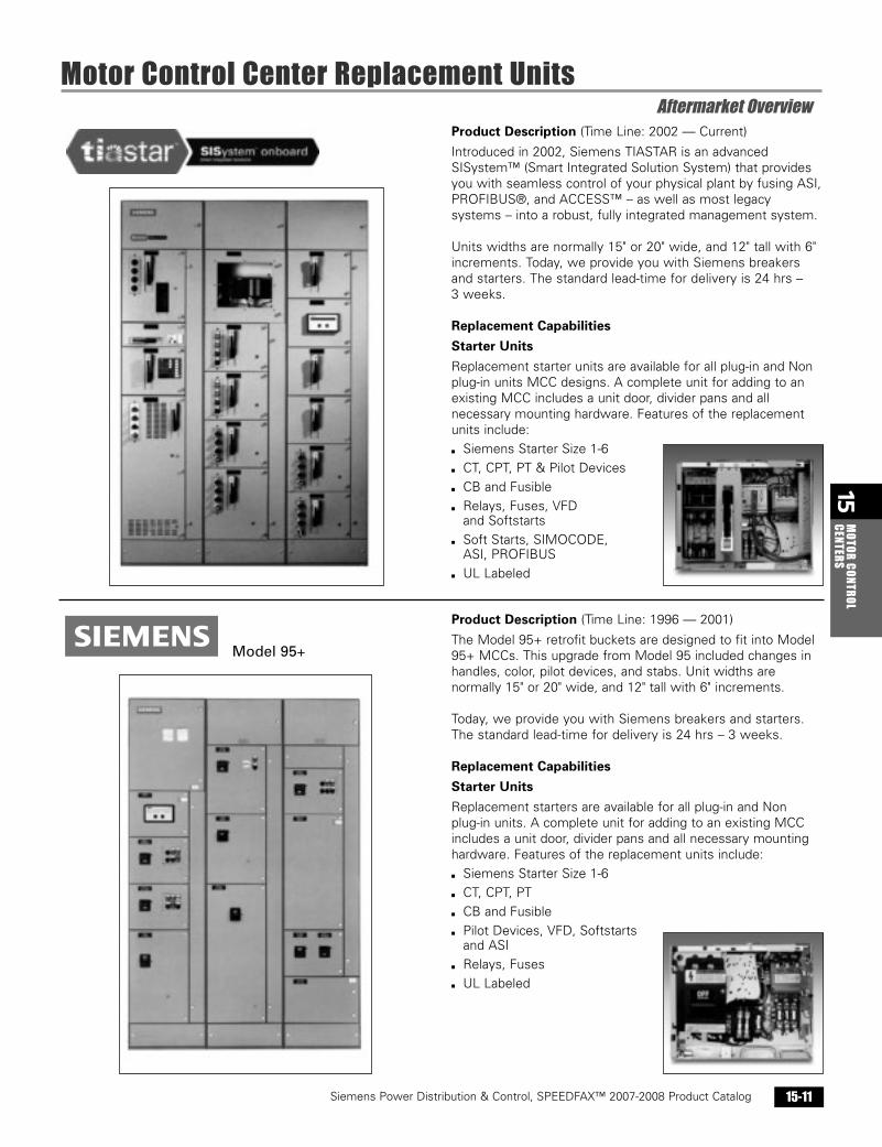
Product Description (Time Line: 1996 — 2001)
The Model 95+ retrofit buckets are designed to fit into Model95+ MCCs. This upgrade from Model 95 included changes inhandles, color, pilot devices, and stabs. Unit widths arenormally 15" or 20" wide, and 12" tall with 6" increments.
Today, we provide you with Siemens breakers and starters.The standard lead-time for delivery is 24 hrs – 3 weeks.
Replacement Capabilities
Starter Units
Replacement starters are available for all plug-in and Non plug-in units. A complete unit for adding to an existing MCCincludes a unit door, divider pans and all necessary mountinghardware. Features of the replacement units include:
▪ Siemens Starter Size 1-6
▪ CT, CPT, PT
▪ CB and Fusible
▪ Pilot Devices, VFD, Softstarts and ASI
▪ Relays, Fuses
▪ UL Labeled
Product Description (Time Line: 2002 — Current)
Introduced in 2002, Siemens TIASTAR is an advancedSISystem™ (Smart Integrated Solution System) that providesyou with seamless control of your physical plant by fusing ASI,PROFIBUS®, and ACCESS™ – as well as most legacysystems – into a robust, fully integrated management system.
Units widths are normally 15" or 20" wide, and 12" tall with 6"increments. Today, we provide you with Siemens breakersand starters. The standard lead-time for delivery is 24 hrs – 3 weeks.
Replacement Capabilities
Starter Units
Replacement starter units are available for all plug-in and Nonplug-in units MCC designs. A complete unit for adding to anexisting MCC includes a unit door, divider pans and allnecessary mounting hardware. Features of the replacementunits include:
▪ Siemens Starter Size 1-6
▪ CT, CPT, PT & Pilot Devices
▪ CB and Fusible
▪ Relays, Fuses, VFD and Softstarts
▪ Soft Starts, SIMOCODE, ASI, PROFIBUS
▪ UL Labeled
Model 95+
Sect_15_Speedfax2007 12/5/06 9:51 AM Page 15-11

15M
OTOR
CON
TROL
CENT
ERS
Siemens Power Distribution & Control, SPEEDFAX™ 2007-2008 Product Catalog15-12
Siemens / Speedfax Previous folio: 15-12
Motor Control Center Replacement UnitsAftermarket Overview
Product Description (Time Line: 1986 — 1997)
The Model 90 retrofit buckets are designed to fit into Model90 MCCs. Unit widths are normally 15" or 20" wide, and 12"tall with 6" increments.
The original Model came with a variety of CB and starters from ITE, C-H, and Siemens 3TF & 3UA Overload. Today, weprovide you with Siemens breakers and starters. The standardlead-time for delivery is 24 hrs – 3 weeks.
Replacement Capabilities
Starter Units
Replacement starters are available for all plug-in and Non plug-in units. A complete unit for adding to an existing MCCincludes a unit door, divider pans and all necessary mountinghardware. Features of the replacement units include:
▪ Siemens Starter Size 1-6
▪ CT, CPT, PT
▪ CB and Fusible
▪ Pilot Devices
▪ Relays and Fuses
Product Description (Time Line: 1995 — 1997)
The Model 95 was originally manufactured in Raleigh, NC.Model 95 served as a style template for many old MCCbuckets since installation procedures and dimensions stayedthe same. Unit widths are normally 15" or 20" wide, and 12"tall with 6" increments.
The original Model came with a variety of CB and startersfrom ITE, C-H and Siemens 3TF & 3UA Overload. Today, weprovide you with Siemens breakers and starters. The standardlead-time for delivery is 24 hrs – 3 weeks.
Replacement Capabilities
Starter Units
Replacement starters are available for all plug-in and Non plug-in units. A complete unit for adding to an existing MCCincludes a unit door, divider pans and all necessary mountinghardware. Features of the replacement units include:
▪ Siemens Starter Size 1-6
▪ CT, CPT, PT
▪ CB and fusible
▪ Pilot Devices
▪ Relays and Fuses
Model 90
Model 95
Sect_15_Speedfax2007 12/5/06 9:52 AM Page 15-12
15M
OTOR CONTROLCENTERS
Siemens Power Distribution & Control, SPEEDFAX™ 2007-2008 Product Catalog 15-13
Siemens / Speedfax Previous folio: 15-13
Motor Control Center Replacement UnitsAftermarket Overview
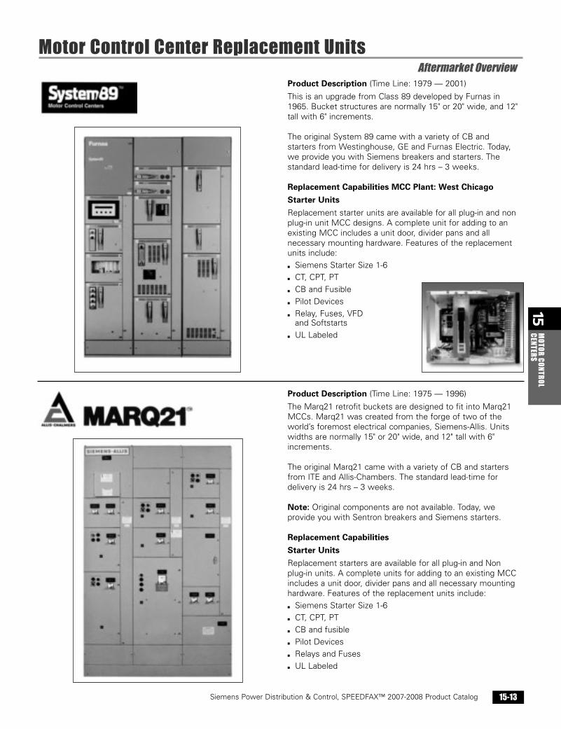
Product Description (Time Line: 1975 — 1996)
The Marq21 retrofit buckets are designed to fit into Marq21MCCs. Marq21 was created from the forge of two of theworld’s foremost electrical companies, Siemens-Allis. Unitswidths are normally 15" or 20" wide, and 12" tall with 6"increments.
The original Marq21 came with a variety of CB and startersfrom ITE and Allis-Chambers. The standard lead-time fordelivery is 24 hrs – 3 weeks.
Note: Original components are not available. Today, weprovide you with Sentron breakers and Siemens starters.
Replacement Capabilities
Starter Units
Replacement starters are available for all plug-in and Non plug-in units. A complete units for adding to an existing MCCincludes a unit door, divider pans and all necessary mountinghardware. Features of the replacement units include:
▪ Siemens Starter Size 1-6
▪ CT, CPT, PT
▪ CB and fusible
▪ Pilot Devices
▪ Relays and Fuses
▪ UL Labeled
Product Description (Time Line: 1979 — 2001)
This is an upgrade from Class 89 developed by Furnas in1965. Bucket structures are normally 15" or 20" wide, and 12"tall with 6" increments.
The original System 89 came with a variety of CB and starters from Westinghouse, GE and Furnas Electric. Today,we provide you with Siemens breakers and starters. Thestandard lead-time for delivery is 24 hrs – 3 weeks.
Replacement Capabilities MCC Plant: West Chicago
Starter Units
Replacement starter units are available for all plug-in and nonplug-in unit MCC designs. A complete unit for adding to anexisting MCC includes a unit door, divider pans and allnecessary mounting hardware. Features of the replacementunits include:
▪ Siemens Starter Size 1-6
▪ CT, CPT, PT
▪ CB and Fusible
▪ Pilot Devices
▪ Relay, Fuses, VFD and Softstarts
▪ UL Labeled
Sect_15_Speedfax2007 12/5/06 9:58 AM Page 15-13

15M
OTOR
CON
TROL
CENT
ERS
Siemens Power Distribution & Control, SPEEDFAX™ 2007-2008 Product Catalog15-14
Siemens / Speedfax Previous folio:15-14
Motor Control Center Replacement UnitsAftermarket Overview
Product Description (Time Line: 1971 — 1992)
The 5600 MCC retrofit buckets are designed to fit into theirold design. 5600 units are 15" wide buckets and the fixmounted panels are 20" wide.
The original Gould came with a variety of old CB and startersfrom ITE, Rowan, and AMP-CAP. These buckets are availableup to NEMA size 5. The standard lead-time for delivery is 24hrs – 3 weeks.
Note: Original components are not available. Today, weprovide you with Sentron™ breakers and Siemens starters.
Replacement Capabilities
Starter Units
Replacement starters are available for all plug-in and Non plug-in units. A complete unit for adding to an existing MCCincludes a unit door, divider pans and all necessary mountinghardware. Features of the replacement units include:
▪ Siemens Starter Size 1-6
▪ CT, CPT, PT
▪ CB and Fusible
▪ Pilot Devices, Relays, and Fuses
▪ UL Labeled
▪ Shelf is ordered separately
Product Description (Time Line: 1972 — 1975)
The Mark 2 retrofit buckets are designed to fit into their olddesign. This is an upgrade from the Mark 1 in ValueLine family.Unit widths are normally 15" or 20" wide, and 12" tall with 6"increments.
The original Mark 2 came with a variety of CB and startersfrom Westinghouse and Allis-Chalmers. The standard leadtimefor delivery is 24 hrs – 3 weeks.
Add-on MCCs:New TIASTAR MCC can be spliced to existing line-up.Note: Original components are not available. Today, weprovide you with Sentron breakers and Siemens starters.
Replacement Capabilities
Starter Units
Replacement starters are available in plug-in Non plug units. Acomplete unit for adding to an existing MCC includes a unitdoor, divider pans and all necessary mounting hardware.Features of the replacement units include:
▪ Siemens Starter Size 1-6
▪ CT, CPT, PT
▪ CB and Fusible
▪ Pilot Devices
▪ Relays, Fuses
▪ UL Labeled
5600
Mark 2
Sect_15_Speedfax2007 12/5/06 2:59 PM Page 15-14