tiara final report draft v4 - CERN Document Server Test Infrastructure and Accelerator Research Area...
10
TIARA-REP-WP6-2014-001 Test Infrastructure and Accelerator Research Area Status Report Final Report on TIARA work package 6 Aiba, M. (PSI) et al 15 January 2014 The research leading to these results has received funding from the European Commission under the FP7-INFRASTRUCTURES-2010-1/INFRA-2010-2.2.11 project TIARA (CNI-PP). Grant agreement no 261905. This work is part of TIARA Work Package 6: SVET R&D Infrastructure. The electronic version of this TIARA Publication is available via the TIARA web site at http://www.eu-tiara.eu/database or on the CERN Document Server at the following URL: http://cds.cern.ch/search?p=TIARA-REP-WP6-2014-001
Transcript of tiara final report draft v4 - CERN Document Server Test Infrastructure and Accelerator Research Area...

TIARA-REP-WP6-2014-001
Test Infrastructure and Accelerator Research Area
Status Report
Final Report on TIARA work package 6
Aiba, M. (PSI) et al
15 January 2014
The research leading to these results has received funding from the European Commissionunder the FP7-INFRASTRUCTURES-2010-1/INFRA-2010-2.2.11 project TIARA (CNI-PP).
Grant agreement no 261905.
This work is part of TIARA Work Package 6: SVET R&D Infrastructure.
The electronic version of this TIARA Publication is available via the TIARA web site athttp://www.eu-tiara.eu/database or on the CERN Document Server at thefollowing URL: http://cds.cern.ch/search?p=TIARA-REP-WP6-2014-001

Final Report on TIARA work package 6: SLS Vertical Emittance Tuning (SVET) Deliverable 6.4 FINAL_R
M. Aiba, M. Böge, N. Milasa, Á. Saá Hernández, M. Rohrer, V. Schlott, A. Streun, PSI, Villigen, Switzerland; F. Antoniou, Y. Papaphilippou, CERN, Geneva, Switzerland; M. Biagini, T. Demmab, S. Guiducci, S. Liuzzoc, P. Raimondi, M. Serio, A. Stella, INFN/LNF, Frascati, Italy; Å. Andersson, J. Breunlin, MAX IV Lab, Lund, Sweden
January 28, 2014
Introduction The main objective of the work package 6 (WP6) „SLS vertical emittance tuning“ (SVET) was to upgrade the Swiss Light Source (SLS) at PSI to enable R&D on ultra-low emittances. There were three areas of activities:
{1} Minimization of vertical emittance: development and application of methods for suppression of betatron coupling and vertical dispersion in the SLS storage ring in order to achieve ultra-low vertical emittance.
{2} Construction of a high resolution beam size monitor: the new beamline X08DA of the SLS was built and commissioned for evaluation of visible and UV light images in order to determine a vertical beam size of a few micron and thus to verify ultra-low vertical emittance.
{3} Measurements on intra-beam scattering: tuning the ring to low vertical emittance and to lower beam energy, measurements of beam parameters as a function of bunch current were performed in order to identify IBS related bunch blow-up.
SVET was a collaboration of four institutes: PSI {2,1,3}, CERN {3,1}, INFN/LNF {1,3} and MAX IV Lab {2}.
Progress and achievements have been well documented in 15 publications up to now (not including this report), see list at end of this paper. In this final report summarizing the complete TIARA preparatory phase 2011-2013 we will do a review of the WP6 activities and report on latest achievements. All activities covered by previous publications will be summarized only in brief.
{1} Minimization of vertical emittance
A. The SLS standard procedure for emittance minimization and the 2011 campaign
During the first year, tools for vertical emittance suppression were developed and applied iteratively. The first step was a beam-assisted re-alignment campaign of the SLS storage ring magnet supports, i.e. a remote alignment of the girders with stored beam at full current while running the fast orbit feedback. This led to a substantial reduction of the rms vertical corrector strength by about 60% and thus to a corresponding reduction of sources of vertical dispersion. On
a now at LNLS, Campinas, Brazil.
b now at LAL, Université Paris-Sud, Orsay, France.
c now at ESRF, Grenoble, France.
the way to a systematic vertical dispersion correction, the beam position monitor (BPM) roll errors were determined in order to eliminate fake vertical dispersion readings caused by the projection of the horizontal dispersion. Then, a model-based correction was applied using 12 dispersive skew quadrupoles to suppress the spurious vertical dispersion. A model-based betatron coupling correction was performed using 24 non-dispersive skew quadrupoles, which reduced the coupling part of the coupled dipole corrector/BPM response matrix to values close to its measurement error. These two correction steps were iterated a few times and lead to a vertical beam size of 4.3 ± 0.6 µm measured with the old beam size monitor. After a final random optimization a vertical beam size of 3.6 ± 0.6 µm corresponding to vertical emittance of 0.9 ± 0.4 pm·rad was eventually achieved in Decemebr 2011, which established a new world record, see Refs. [3, 5] for details.
B. Application of the Low Emittance Tuning (LET) method 2011/2012
The LET algorithm uses an extended, double linear system for combined correction of linear optics and suppression of coupling: the vertical system uses a measurement vector composed from vertical orbit and dispersion and the off-diagonal blocks of the orbit response matrix, and a knob vector containing vertical correctors and skew quadrupoles. The horizontal system uses a measurement vector composed from horizontal orbit and dispersion and the diagonal blocks of the response matrix, and a knob vector containing horizontal correctors. Both systems may also include BPM roll errors. The vertical system will provide correction of vertical dispersion and coupling, and the horizontal system will provide correction of linear optics, i.e. beta functions and horizontal dispersion similar to a LOCO (Linear Optics from Closed Orbit) procedure. Factors can be applied to shift weights between optics correction and coupling suppression. LET has potential to further reduce vertical dispersion, since it employs vertical orbit bumps, which sample vertical dipole fields in quadrupoles and skew quadrupole fields in sextupoles – a technique also known as dispersion-free steering. LET was applied to the SLS in only 3 machine development shifts during August 2011 and March 2012, but nevertheless succeeded to suppress the beam size down to 4.4 ± 0.4stat ± 0.6sys µm, measured at the old monitor, corresponding to an emittance of ≈1.3 pm·rad, see Refs. [3,7] for details.
C. Emittance minimization using the new monitor in 2013
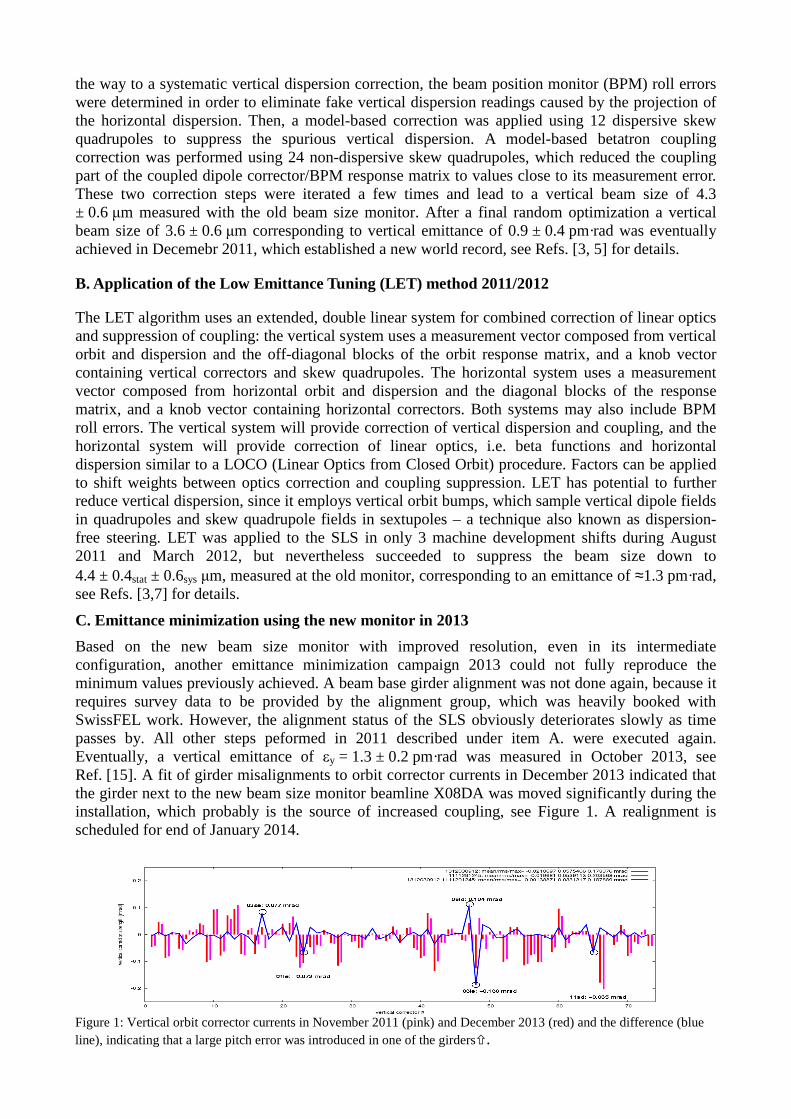
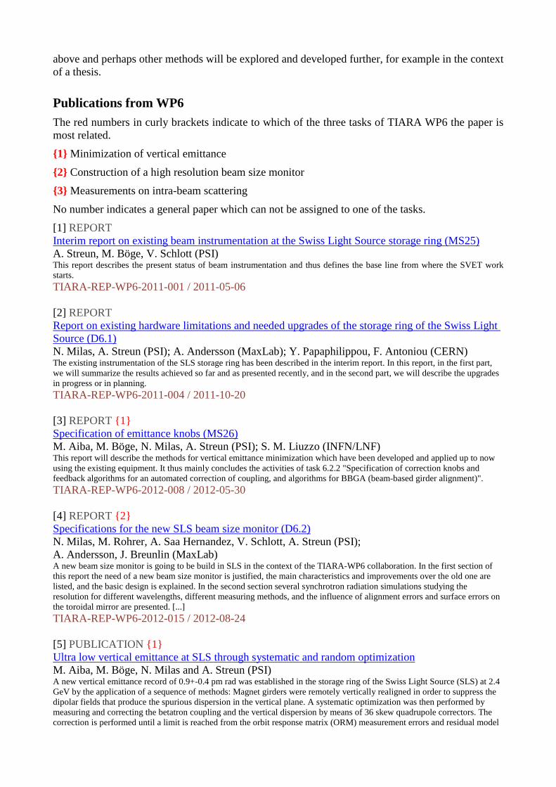
Based on the new beam size monitor with improved resolution, even in its intermediate configuration, another emittance minimization campaign 2013 could not fully reproduce the minimum values previously achieved. A beam base girder alignment was not done again, because it requires survey data to be provided by the alignment group, which was heavily booked with SwissFEL work. However, the alignment status of the SLS obviously deteriorates slowly as time passes by. All other steps peformed in 2011 described under item A. were executed again. Eventually, a vertical emittance of εy = 1.3 ± 0.2 pm·rad was measured in October 2013, see Ref. [15]. A fit of girder misalignments to orbit corrector currents in December 2013 indicated that the girder next to the new beam size monitor beamline X08DA was moved significantly during the installation, which probably is the source of increased coupling, see Figure 1. A realignment is scheduled for end of January 2014.
Figure 1: Vertical orbit corrector currents in November 2011 (pink) and December 2013 (red) and the difference (blue line), indicating that a large pitch error was introduced in one of the girders�.

D. Conclusion on vertical emittance minimization
The vertical emittance minimization proceeded fast and was very successful. Values of about 1.5...2.0 pm·rad can be routinely achieved by application of systematic and random procedures established at SLS. Values beyond require girder realignments, BPM roll error determination and several machine development shifts. A value of about 1 pm·rad was reached and set a new world record; this is only 5 times larger than the fundamental quantum limit of vertical emittance at SLS. It is not clear yet if it will be possible to reach lower values in future. Application of the LET algorithm started successfully and was quite promising, however was not continued further, since relevant persons left the collaboration.
{2} Construction of a high resolution beam size monitor Analysis of the SLS instrumentation, see Refs. [1,2], found need for action with regard to vertical beam size measurement and reconditioning of the girder mover system. Against initial expectations, the BPM system performance turned out to be fully sufficient. While the girder movers were fixed relatively quickly, an improvement of vertical beam size measurement required a new monitor beamline and thus became the core part of WP6 considering both hardware funding and manpower.
A. Monitor specifications
The existing monitor, based on vertically polarized visible and near UV synchrotron radiation imaging, had been pushed to its very limit of resolution at beam sizes of about 4 µm. A new monitor, based on the same method of measurement, was designed for an ultimate resolution of 2 µm and for improved operating conditions through realization as a small beam line, which extends out of the storage ring tunnel. Thus, the magnification is increased compared to the old monitor due to the longer optical path, and the optical end station containing cameras, filters etc. is accessible during operation. Fully reflective optics including a toroidal mirror is employed for wavelength-independent focusing instead of using a lens like the old monitor, which would require adjustment of camera positions for different wavelengths. Spectral range is extended down to UV light of 266 nm, because shorter wavelength gives better resolution. Introducing obstacles of different sizes into the beam path turns the imaging method into a interferometric method and thus provides cross-checks through variations of the measurement method. The beam path is of zigzag shape to avoid any bremsstrahlung or hard x-ray SR from the ring reaching the end station. A set of remotely controlled alignment lasers and pinholes was included for calibration. The main optical elements, i.e. the toroidal mirror and a planar mirror are supported by motorized gimbal mounts which allow horizontal and vertical angles to be adjusted remotely. The complete beamline was modelled using the program Synchrotron Radiation Workshop (SRW), and in particular possible misalignments of the toroidal mirror were studied thoroughly. For details of the monitor specification see Refs. [4,9].
B. Monitor construction
The monitor became a complete beam line on its own, named X08DA, including a front end with shutters, a vacuum system containing the focusing optics, several motors and switches with their power supplies and controllers, and a hutch outside the tunnel with local computers and personnel safety system. A detailed work plan for the PSI services was established, and all work was executed according to schedule during the year 2012 and early 2013, thus the first synchrotron light could be seen in the hutch at Jan. 29, 2013.
The toroidal mirror, which is the central component of the monitor, required detailed studies on tolerances, choice of material and selection of possible suppliers, so it was ordered not earlier than Dec. 2012. Delivery was scheduled by the company for Oct. 2013 but further delayed, until it finally arrived in Nov. 2013. So, the monitor was first realized in an intermediate configuration using a plano-convex lens and a flat mirror in place of the toroidal mirror. In Jan. 2014, the toroidal mirror was installed and the beam line was commissoned in its final configuration.
C. Monitor commissioning: 2013
A thorough alignment of the optical components was done in 2013, first in the laboratory, then at the beam line using alignment lasers, and finally using the synchrotron radiation. Eventually, the intermediate lens configuration was aligned in Dec. 2013 to very high quality, in order to characterize and document the full optical system before the lens is exchanged for the toroidal monitor [publication in preparation].
Measurements were done mainly at 325 nm using a 3.75 µm pixel camera, and also at 266 nm using a 8 µm pixel UV camera. Imaging and interference methods using obstacles of three different sizes were applied and showed excellent agreement, well within the statistical error band of the beam size measurement. The error margin is dominated by shot-to-shot fluctuations, which seem to be caused by mechanical vibrations in the beam line. Camera exposure times were set to a low value of 0.4 ms as a compromise to still get sufficient light intensity. Work is in progress to understand and suppress these vibrations, to chacterize the true resolution of the optical system and to estimate its systematic error. Lowest beam size values down to 4 µm have been observed using the new monitor without yet reaching its limit of resolution, but lower beam size was not feasible due to the limitations of the coupling control procedure, see {1} . Lowest emittance measured so far was εy = 1.3 ± 0.2 pm·rad in Oct. 2013. The value is larger than the record value from Dec. 2011, but the error margin is significantly reduced compared to the old monitor. For details see Ref. [15]; early commissioning results had been reported in Refs. [10,11].
D. Monitor commissioning: January 2014
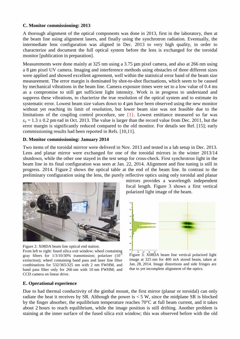
Two items of the toroidal mirrror were deliverd in Nov. 2013 and tested in a lab setup in Dec. 2013. Lens and planar mirror were exchanged for one of the toroidal mirrors in the winter 2013/14 shutdown, while the other one stayed in the test setup for cross-check. First synchrotron light in the beam line in its final configuration was seen at Jan. 22, 2014. Alignment and fine tuning is still in progress. 2014. Figure 2 shows the optical table at the end of the beam line. In contrast to the preliminary configuration using the lens, the purely reflective optics using only toroidal and planar
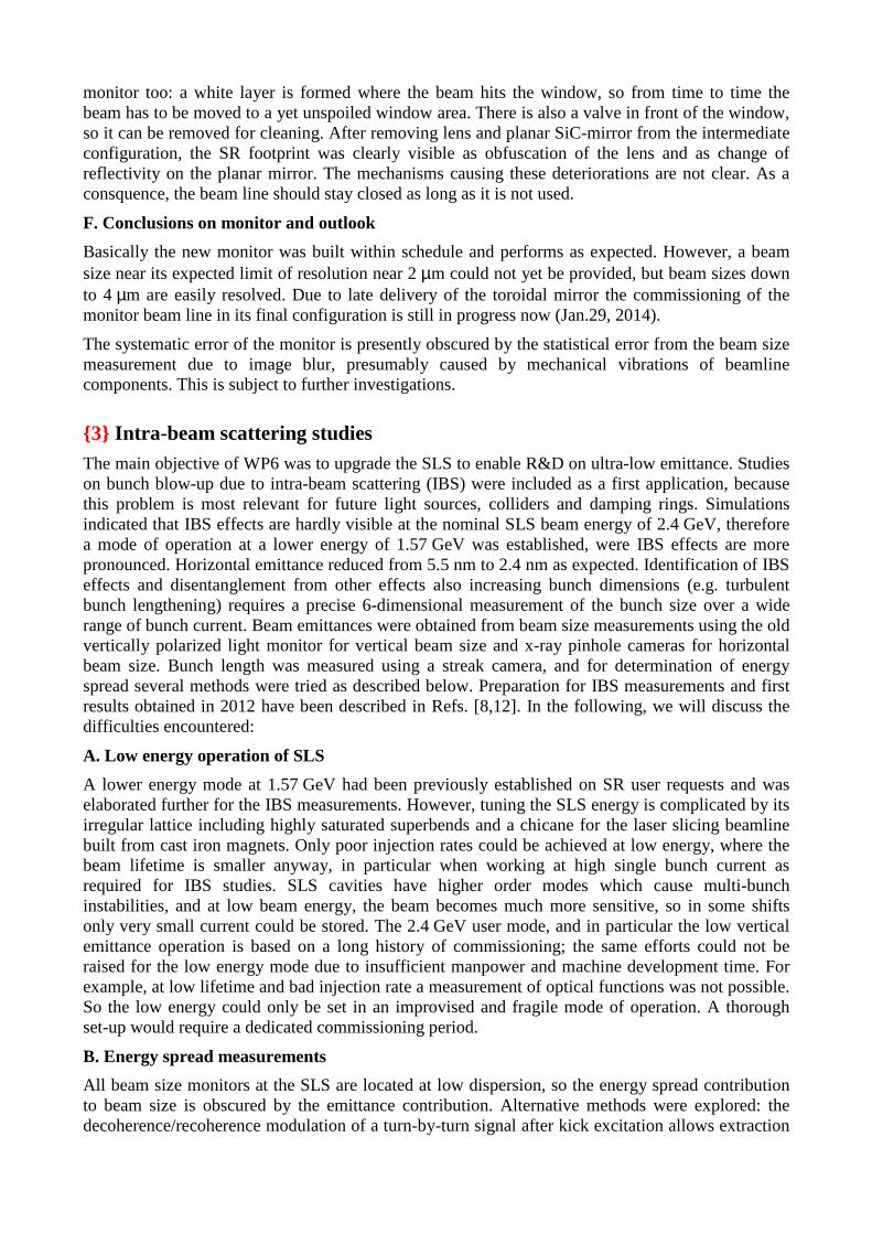
mirrors provides a wavelength independent focal length. Figure 3 shows a first vertical polarized light image of the beam.
E. Operational experience
Due to bad thermal conductivity of the gimbal mount, the first mirror (planar or toroidal) can only radiate the heat it receives by SR. Although the power is < 5 W, since the midplane SR is blocked by the finger absorber, the equilibrium temperature reaches 70°C at full beam current, and it takes about 2 hours to reach equilibrium, while the image position is still drifting. Another problem is staining at the inner surface of the fused silica exit window; this was observed before with the old
Figure 2: X08DA beam line optical end station. From left to right: fused silica exit window; wheel containing gray filters for 1/3/10/30% transmission; polarizer (10-5 extinction); wheel containing band pass and laser line filter combinations for 532/365/325 nm with 2 nm FWHM, and band pass filter only for 266 nm with 10 nm FWHM; and CCD camera on linear drive.
Figure 3: X08DA beam line vertical polarized light image at 325 nm for 400 mA stored beam, taken at Jan. 28, 2014. Image distortions and side fringes are due to yet incomplete alignment of the optics.
monitor too: a white layer is formed where the beam hits the window, so from time to time the beam has to be moved to a yet unspoiled window area. There is also a valve in front of the window, so it can be removed for cleaning. After removing lens and planar SiC-mirror from the intermediate configuration, the SR footprint was clearly visible as obfuscation of the lens and as change of reflectivity on the planar mirror. The mechanisms causing these deteriorations are not clear. As a consquence, the beam line should stay closed as long as it is not used.
F. Conclusions on monitor and outlook
Basically the new monitor was built within schedule and performs as expected. However, a beam size near its expected limit of resolution near 2 µm could not yet be provided, but beam sizes down to 4 µm are easily resolved. Due to late delivery of the toroidal mirror the commissioning of the monitor beam line in its final configuration is still in progress now (Jan.29, 2014).
The systematic error of the monitor is presently obscured by the statistical error from the beam size measurement due to image blur, presumably caused by mechanical vibrations of beamline components. This is subject to further investigations.
{3} Intra-beam scattering studies The main objective of WP6 was to upgrade the SLS to enable R&D on ultra-low emittance. Studies on bunch blow-up due to intra-beam scattering (IBS) were included as a first application, because this problem is most relevant for future light sources, colliders and damping rings. Simulations indicated that IBS effects are hardly visible at the nominal SLS beam energy of 2.4 GeV, therefore a mode of operation at a lower energy of 1.57 GeV was established, were IBS effects are more pronounced. Horizontal emittance reduced from 5.5 nm to 2.4 nm as expected. Identification of IBS effects and disentanglement from other effects also increasing bunch dimensions (e.g. turbulent bunch lengthening) requires a precise 6-dimensional measurement of the bunch size over a wide range of bunch current. Beam emittances were obtained from beam size measurements using the old vertically polarized light monitor for vertical beam size and x-ray pinhole cameras for horizontal beam size. Bunch length was measured using a streak camera, and for determination of energy spread several methods were tried as described below. Preparation for IBS measurements and first results obtained in 2012 have been described in Refs. [8,12]. In the following, we will discuss the difficulties encountered:
A. Low energy operation of SLS
A lower energy mode at 1.57 GeV had been previously established on SR user requests and was elaborated further for the IBS measurements. However, tuning the SLS energy is complicated by its irregular lattice including highly saturated superbends and a chicane for the laser slicing beamline built from cast iron magnets. Only poor injection rates could be achieved at low energy, where the beam lifetime is smaller anyway, in particular when working at high single bunch current as required for IBS studies. SLS cavities have higher order modes which cause multi-bunch instabilities, and at low beam energy, the beam becomes much more sensitive, so in some shifts only very small current could be stored. The 2.4 GeV user mode, and in particular the low vertical emittance operation is based on a long history of commissioning; the same efforts could not be raised for the low energy mode due to insufficient manpower and machine development time. For example, at low lifetime and bad injection rate a measurement of optical functions was not possible. So the low energy could only be set in an improvised and fragile mode of operation. A thorough set-up would require a dedicated commissioning period.
B. Energy spread measurements
All beam size monitors at the SLS are located at low dispersion, so the energy spread contribution to beam size is obscured by the emittance contribution. Alternative methods were explored: the decoherence/recoherence modulation of a turn-by-turn signal after kick excitation allows extraction

of energy spread if chromaticity and synchrotron tune have been measured by other means [i]. However, the fit was fragile and the error too large, furthermore, turn-by-turn mixing distorts the signals. A very similar method operates in frequency space, evaluating the tune spectrum. The ratio of synchrotron side band peak to fundamental peak height contains the energy spread [ii]. This was implemented, however due to impedance effects, the upper and lower side-bands were unequal, in some cases even the idenfication of the fundamental was not clear. It was beyond the scope of the IBS related work to explore the method further including impedance models.
Other methods analyze the undulator spectra: the first trial used high harmonics of the UE54 undulator of the Phoenix beamline, because this undulator has exceptionally low phase errors, so its spectrum extends beyond the 40th harmonics, and the spectral lines become more narrow with increasing harmonic number. Tests with different bunch currents did not show any variation, obviously any energy spread related effect was obscured by the limited energy resolution of the beamline optics or by line widening due to other effects, e.g. phase errors. Next trial was at the U19 planar undulators of the protein cristallography, trying to find a shift of the blue edge of the lines due to widening by energy spread, but beamline energy resolution was insufficient to reveal any effect. Finally, U19 of the microXAS was used, since this beamline has the best energy resolution and uses a refocusing optics and a Si(311) crystal. Energy spread can be extracted from peak width and also from the ratio of harmonic peak and the red-shifted hump [iii]. But reproducibility of the measurements was very poor, the results were extremely sensitive on the orbit position inside the insertion device. However, in low current, low energy operation, the orbit control is much worse that at nominal energy and full current, where these first tests had been done. All the trials using undulator spectra suffered from the very limited availability of the beamlines, which are usually set-up for user operation, and on the limited time, beamline experts can donate to machine development tasks. So, all these experiments did not explore the problem to great depth. Much more work would have been needed.
[ i ] A. Sargsyan, NIM A 638 (2011) 15-18. [ ii] T. Nakamura et al., Proc. PAC 2001, Chicago, p.1972. [iii] E.Tarazona & P. Elleaume, Rev.Sci.Instrum.67,3368 (1996).
C. Conclusion on IBS studies
Some measurements could be done in 2012 and allowed comparison to IBS simulations [12], but further progress was slow due to the complications of low energy operation and energy spread measurements, and due to absence (two maternity leaves) of relevant persons. Anyway, the IBS measurements were no official tasks (not listed in Gantt chart) and thus were given lower priority.
Conclusions and Outlook
The goal of WP6 „to upgrade the SLS to enable R&D on ultra-low emittance“ was reached: methods to realize ultra-low vertical emittance have been established and a high resolution monitor was built and successfully put into operation, which allows verification of ultra-low emittance. Measurements of intra beam scattering were performed as a first application of R&D at ultra-low emittance, but suffered from difficulties in tuning the SLS to lower energy and to measure the energy spread. The SLS is no test accelerator but a user facility which has to run 5000 hours per year at 98% availability for the experiments, and has been highly optimized for its standard user mode of operation. This impedes machine studies which require the storage ring to be tuned to very different conditions of operation.
Task {1} to realize ultra-low vertical emittance will continue by further alignment campaigns, also automated coupling control still has to be implemented for user operation. Task {2} , the monitor commissioning is in progress and is expected to be completed during February 2014. Task {3} , the IBS measurements require a reliable method of energy spread measurement. The methods described
above and perhaps other methods will be explored and developed further, for example in the context of a thesis.
Publications from WP6 The red numbers in curly brackets indicate to which of the three tasks of TIARA WP6 the paper is most related.
{1} Minimization of vertical emittance
{2} Construction of a high resolution beam size monitor
{3} Measurements on intra-beam scattering
No number indicates a general paper which can not be assigned to one of the tasks.
[1] REPORT Interim report on existing beam instrumentation at the Swiss Light Source storage ring (MS25) A. Streun, M. Böge, V. Schlott (PSI) This report describes the present status of beam instrumentation and thus defines the base line from where the SVET work starts. TIARA-REP-WP6-2011-001 / 2011-05-06 [2] REPORT Report on existing hardware limitations and needed upgrades of the storage ring of the Swiss Light Source (D6.1) N. Milas, A. Streun (PSI); A. Andersson (MaxLab); Y. Papaphilippou, F. Antoniou (CERN) The existing instrumentation of the SLS storage ring has been described in the interim report. In this report, in the first part, we will summarize the results achieved so far and as presented recently, and in the second part, we will describe the upgrades in progress or in planning. TIARA-REP-WP6-2011-004 / 2011-10-20 [3] REPORT {1} Specification of emittance knobs (MS26) M. Aiba, M. Böge, N. Milas, A. Streun (PSI); S. M. Liuzzo (INFN/LNF) This report will describe the methods for vertical emittance minimization which have been developed and applied up to now using the existing equipment. It thus mainly concludes the activities of task 6.2.2 "Specification of correction knobs and feedback algorithms for an automated correction of coupling, and algorithms for BBGA (beam-based girder alignment)". TIARA-REP-WP6-2012-008 / 2012-05-30 [4] REPORT {2} Specifications for the new SLS beam size monitor (D6.2) N. Milas, M. Rohrer, A. Saa Hernandez, V. Schlott, A. Streun (PSI); A. Andersson, J. Breunlin (MaxLab) A new beam size monitor is going to be build in SLS in the context of the TIARA-WP6 collaboration. In the first section of this report the need of a new beam size monitor is justified, the main characteristics and improvements over the old one are listed, and the basic design is explained. In the second section several synchrotron radiation simulations studying the resolution for different wavelengths, different measuring methods, and the influence of alignment errors and surface errors on the toroidal mirror are presented. [...] TIARA-REP-WP6-2012-015 / 2012-08-24 [5] PUBLICATION {1} Ultra low vertical emittance at SLS through systematic and random optimization M. Aiba, M. Böge, N. Milas and A. Streun (PSI) A new vertical emittance record of 0.9+-0.4 pm rad was established in the storage ring of the Swiss Light Source (SLS) at 2.4 GeV by the application of a sequence of methods: Magnet girders were remotely vertically realigned in order to suppress the dipolar fields that produce the spurious dispersion in the vertical plane. A systematic optimization was then performed by measuring and correcting the betatron coupling and the vertical dispersion by means of 36 skew quadrupole correctors. The correction is performed until a limit is reached from the orbit response matrix (ORM) measurement errors and residual model

deficiencies. At this point, the method of random optimization (RO), a multi-variable optimization procedure, was invoked. In the present experiment, the vertical beam size is the target function while the skew quadrupole currents act as the correction variables. TIARA-PUB-WP6-2012-001 / 2012-10-16 [6] CONFERENCE PAPER {1} SLS Vertical emittance tuning (IPAC11) M. Böge, M. Aiba, N. Milas, A. Streun (PSI); S. M. Liuzzo (INFN/LNF) To establish ultra-small vertical emittances (<1 pm.rad at 2.86 GeV) is one important aim of future linear collider damping ring optimization studies (In January 2011, the EU-project TIARA (Test Infrastructure and Accelerator Research Area) started with contributions from the SLS as part of the SVET (SLS Vertical Emittance Tuning) work package WP6 [1].) at the SLS. TIARA-CONF-WP6-2011-002 / 2011-09-04 [7] CONFERENCE PAPER {1} Tests of low emittance tuning techniques at SLS and DAFNE (IPAC12) S.M. Liuzzo, M.E. Biagini, P. Raimondi (INFN/LNF); M. Aiba, M. Böge (PSI) The SuperB collider design is based on extremely low emittances, comparable to those of synchrotron light sources. A Low Emittance Tuning (LET) algorithm was developed for SuperB and has been tested last year at DIAMOND. This paper will report on the results of the application of LET to SLS (PSI) and DAFNE (LNF) in order to compare and confirm the previous results. TIARA-CONF-WP6-2012-002 / 2012-06-21 [8] CONFERENCE PAPER {3} Preparation of SLS for IBS measurements (IPAC12) N. Milas, M. Aiba, M. Böge, A. Lüdeke, A. Saa Hernandez, A. Streun (PSI); F. Antoniou, Y. Papaphilippou (CERN) It is planned to use the Swiss Light Source (SLS) for testing damping ring issues related to linear colliders. One aspect is the study of Intra-Beam Scattering (IBS) effects, which are a limiting factor for ultra-low emittance rings. In this paper we present the setup and characterization of a new mode of operation in which the SLS runs at lower energy (1.57 GeV) with a natural emittance of 2.4 nm rad. TIARA-CONF-WP6-2012-003 / 2012-06-21 [9] CONFERENCE PAPER {2} Design and expected performance of the new SLS beam size monitor (IBIC12) N. Milas, M. Rohrer, A. Saa Hernandez, V. Schlott, A. Streun (PSI); A. Andersson, J. Breunlin (MaxLab) The vertical emittance minimization campaign at SLS, realized in the context of the TIARA WP6, has already achieved the world's smallest vertical beam size of 3.6 micrometer, corresponding to a vertical emittance of 0.9 pm, in a synchrotron light source. The minimum value reached for the vertical emittance is only about five times larger than the quantum limit of 0.2 pm. TIARA-CONF-WP6-2012-005 / 2012-10-16 [10] CONFERENCE PAPER {2} The new SLS beam size monitor, first results (IPAC13) A. Saa Hernandez, N. Milas, M. Rohrer, V. Schlott, A. Streun (PSI); A. Andersson, J. Breunlin, (MAX IV Laboratory) An extremely small vertical beam size of 3.6 µm, corresponding to a vertical emittance of 0.9 pm, only about five times bigger than the quantum limit, has been achieved at the storage ring of the Swiss Light Source (SLS). The measurement was performed by means of a beam size monitor based on the imaging of the vertically polarized synchrotron radiation in the visible and UV spectral ranges. However, the resolution limit of the monitor was reached during the last measurement campaign and prevented further emittance minimization. In the context of the work package SLS Vertical Emittance Tuning of the TIARA collaboration, a new improved monitor was built. It provides larger magnification, an increase of resolution and enables two complementary methods of measurement: imaging and interferometry. In this paper we present the design, installation, commissioning, performance studies and first results obtained with the new monitor. TIARA-CONF-WP6-2013-003 / 2013-07-15

[11] CONFERENCE PAPER {2} Commissioning experience and first results from the new SLS beam size monitor (IBIC13) V. Schlott, M. Rohrer, A. Saa Hernandez, N. Milas, A. Streun (PSI); A. Andersson, J. Breunlin, (MAX IV Laboratory) In the context of the TIARA work package “SLS vertical emittance tuning” (SVET), an extremely small vertical beam size of 3.6 µm, corresponding to a vertical emittance of 0.9 pm, was verified using an optical monitor based on imaging of pi-polarized light. Since the existing beam size monitor reached its limit of resolution, a new monitor beam line was designed and installed at the 08BD bending magnet of the Swiss Light Source (SLS) storage ring. Larger magnification and operation at shorter wavelength provide improved spatial resolution. Reflective optics enables convenient switching between different wavelengths. An optical table is located in a hutch outside the storage ring tunnel to provide access during operation. Movable obstacles in the beam path create interference patterns and thus provide redundancy of model based analysis of the images. In this paper we report on our commissioning experience and provide a comparison of the different measurement methods at different wavelengths. TIARA-CONF-WP6-2013-004 / 2013-10-23 [12] NOTE {3} Intrabeam scattering studies at the Swiss Light Source (IPAC 2012) F. Antoniou, Y. Papaphilippou (CERN); M. Aiba, M. Böge, N. Milas, A. Streun (PSI); T. Demma (CNRS/IN2P3/LAL, Université Paris-Sud) The target parameters of modern ultra-low emittance rings are entering into a regime where Intra-beam Scattering (IBS) becomes important and, in the case of linear collider damping rings, even a limitation for the delivered emittances. The Swiss Light Source (SLS) storage ring, as it has achieved a vertical geometrical emittance of around 1 pm at 2.4 GeV [1], and it has the ability to run at even lower energies, and the availability of emittance monitoring diagnostics, is an ideal testbed for IBS studies. Simulations are undertaken using the classical IBS theories and tracking codes in order to explore the possibilities and limitations for IBS measurements at the SLS. In this respect, comparison between the theories and codes is first discussed. The dependence of the output emittances, taking into account the effect of IBS, with respect to energy, bunch charge and zero current vertical and longitudinal emittance is also studied, in order to define the regimes where the IBS effect can be significant. First measurement results from the SLS are finally presented. TIARA-NOTE-WP6-2012-001 / 2012-07-02 [13] NOTE {1} Random Walk optimization in accelerators - vertical emittance tuning at SLS (IPAC 2012) M. Aiba, M. Böge, N. Milas and A. Streun (PSI) The high performance of an accelerator is realized through various model-based corrections utilizing beam measurements. These corrections are, however, limited by measurement errors as well as model deficiencies. To overcome these limitations and further push up the performance, we investigated the application of a random walk optimization (RWO) technique. An application to the coupling correction at the SLS was successful to significantly lower the vertical emittance even after elaborate model-based corrections were applied. The methodology of RWO and potential applications of the technique are discussed. TIARA-NOTE-WP6-2012-002 / 2012-07-04 [14] NOTE {1} SLS: Pushing the Envelope Based on Stability M. Aiba, P. Beaud, M. Böge, G. Ingold, B. Keil, A. Lüdeke, N. Milas, L. Rivkin, Á. Saá Hernández, T. Schilcher, V. Schlott, A. Streun (PSI) Technical report published in Synchrotron Radiation News, Volume 26, Issue 3, 22 May 2013 This paper was invited to SRN by the editor (A. Zholents). It reviews top-up operation at SLS and reports on two major achievements based on stability, namely short pulse generation and ultra-low vertical emittance operation. TIARA-NOTE-WP6-2013-002 / 2013-06-03 [15] NOTE {2} Ultra-Low Vertical Beam Size Instrumentation and Emittance Determination at the Swiss Light Source A. Saa Hernandez, M. Aiba, M. Böge, N. Milas, M. Rohrer, V. Schlott, A. Streun (PSI); A. Andersson, J. Breunlin (MaxLab) ICFA beam dynamics newsletter Vol.62, Dec.2013. TIARA-NOTE-WP6-2013-005 / 2013-12-12