TI TDA2x Based xCAM Configuration and User Guideradiumboards.com/RB_VVDN_TI TDA2x xCAM Configuration...
27
© 2014 RadiumBoards All Rights Reserved TI TDA2x Based xCAM Configuration and User Guide Revision 1.0
Transcript of TI TDA2x Based xCAM Configuration and User Guideradiumboards.com/RB_VVDN_TI TDA2x xCAM Configuration...

© 2014 RadiumBoards All Rights Reserved
TI TDA2x Based
xCAM Configuration and User Guide
Revision 1.0

© 2014 RadiumBoards Page 2 of 27 All Rights Reserved
TI TDA2x Based xCAM User Guide
V1.0
Copyright Notice
This document is copyrighted material of RadiumBoards, All Rights Reserved. No part of
this document, in whole or in part, may be used, reproduced, stored in a retrieval system or
transmitted, in any form, or by any means, electronic or otherwise, including photocopying,
reprinting, or recording, for any purpose, without the express written permission of
RadiumBoards.
Legal Disclaimer
The information contained in this document is subject to change without notice. The
information in this document is provided for informational purposes only. RadiumBoards
specifically disclaims all warranties, express or limited, including, but not limited, to the
implied warranties of merchantability and fitness for a particular purpose, except as provided
for in a separate software license agreement.
RadiumBoards
RadiumBoards is a unique website providing complete board and software solutions
addressing a broad range of markets including Security and Surveillance, Networking,
Wireless, Video, Audio, Automotive, Mobile Device and IOT (Internet of Things).
OEMs and Systems Integrators can shop for complete assemblies, with firmware, BSP and
applications ready to integrate into your own enclosures.
ODMs can shop for reference designs complete with full BSP (Board Support Package) and
application support. Radium Boards can also provide any level of customization to the
hardware or software required by the ODM to help differentiate in their markets.
Electronics hardware and software hobbyists, experimenters and educators now have access
to complete high performance platforms for application in an infinite range of projects.

© 2014 RadiumBoards Page 3 of 27 All Rights Reserved
TI TDA2x Based xCAM User Guide
V1.0
Correspondence
Corporate Office
B-22, Infocity Sector-34,
Gurgaon-122001, Haryana, India
Tel No: +91 124 4284250
US Office
2025 Gateway Place, Suite 465
San Jose, California 95110
WEBSITE
www.radiumboards.com
VVDN Technologies
VVDN Technologies Pvt. Ltd. is a sibling company of RadiumBoards and is responsible for
the design and development of all products sold through the RadiumBoards brand.
Founded in 2007, VVDN is a technology innovation and development company providing a
broad spectrum of services and technology expertise to our core domains. VVDN provides
“Concept to Customer” services at any point in the development cycle, as well as full turnkey
solutions.
WEBSITE
www.vvdntech.com

© 2014 RadiumBoards Page 4 of 27 All Rights Reserved
TI TDA2x Based xCAM User Guide
V1.0
........................................................................................... 6
......................................................................................................... 6
.................................................................................... 6
....................................................................................... 7
....................................................................................................................... 8
............................................................................................................... 8
...................................................................................... 11
............................................................................................ 12
........................................................................................... 19
......................................................................................... 21
........................................................................................................ 21
...................................................................................................... 22
....................................................................................... 23
......................................................................... 23
........................................................................................ 24
............................................................................. 25
................................................................................... 26
....................................................................................... 26
................................................................................................ 27
Figures
.......................................................................................... 9
FIGURE 2:TDA2X MAIN BOARD ...................................................................................... 12
FIGURE 3: ADD ON INTERFACE BOARD ......................................................................... 13
FIGURE 4: MAIN IMAGE SENSOR BOARD ...................................................................... 13
.................................................................................................... 14
................................................................................................. 15
FIGURE 7: POWER BOARD .............................................................................................. 15
................................................. 16
............................ 17
........................... 19
........................................................ 20
.................................................................. 20
............................................................................ 22
........................................................................................................................... 24
FIGURE 15: SIMPLIFIED RADAR PROCESSING FLOW HARDWARE/SOFTWARE
DATAFLOW DIAGRAM .................................................................................................... 25

© 2014 RadiumBoards Page 5 of 27 All Rights Reserved
TI TDA2x Based xCAM User Guide
V1.0
........................................................................................................................... 26
............................................................. 26
....................................................... 27
TABLES
TABLE 1: DOCUMENT CONVENTIONS ............................................................................. 6
TABLE 2: TERMS AND ABBREVIATIONS .......................................................................... 7
TABLE 3: TECHNICAL SPECIFICATIONS ........................................................................ 11
TABLE 4: XCAM INTERFACE DESCRIPTION ................................................................... 18

© 2014 RadiumBoards Page 6 of 27 All Rights Reserved
TI TDA2x Based xCAM User Guide
V1.0
1. About This Document
1.1 Introduction
This document provides details of the xCAM including its features, functionality,
installation and configuration.
1.2 Document Conventions
The different conventions used in this document are explained in the following table:
Convention Description
: Provides information about important
features or instructions.
: Alerts you to potential damage to a
program, device, or system.
: Alerts you to potential injury or
fatality and to potential electrical hazards.
Any option that needs to be selected or typed
in the user interface is represented using bold
font.
Table 1: Document Conventions

© 2014 RadiumBoards Page 7 of 27 All Rights Reserved
TI TDA2x Based xCAM User Guide
V1.0
1.3 Terms and Abbreviations
The different terms and abbreviations used in this document are explained in Table 2 below.
Table 2: Terms and Abbreviations
Terms / Abbreviation Description / Expansion
ADAS Advanced Driving Assistance System
VS Video Security
DSS Display Subsystem
GUI Graphical User Interface
LSP Linux Support Package
MB/s Mega Byte per second
Mbps Mega bit per second
OSD On Screen Display
PTZ Pan Tilt Zoom
TOF Time of Flight
RTSP Real Time Streaming Protocol
SDK Software Development Kit
UI User Interface
MSFP Multi Sensor Fusion Platform

© 2014 RadiumBoards Page 8 of 27 All Rights Reserved
TI TDA2x Based xCAM User Guide
V1.0
2. xCAM
The xCAM coupled with multiple advanced sensor systems, is intended for evaluation and
use in Advanced Driver Assistance Systems (ADAS).
The design features the Texas Instruments TDA2x Video Processor, running on 1GB of
DDR3L memory which can be upgraded to 2GB.
The xCAM contains a comprehensive blend of advanced sensors which enable OEMs and
ODMS to evaluate, develop and rapidly deploy advanced ADAS systems resulting in faster
time to market with minimal engineering effort. Customers can use and further upgrade the
hardware files with the downloadable files provided as open source from TI.
The comprehensive sensor suite supported by xCAMnincludes:
• TDA2x ADAS Media Processor Board (Main Board)
• Add On Interface Board
• FPD Link Board
• Power Supply Board
• Sensor Boards
2.1 Features
The TDA2x based xCAM captures image data from an image sensor, encodes the image
stream, and performs analytics functions on the video and streams data over Ethernet as well
as stores data on local storage. It provides live high definition video via HDMI.
In addition, it also has event-triggered inputs and alarm outputs. Peripheral connection and
system control via RS-485, USB and SD memory card is enabled by the appropriate
hardware connections to the TDA2x Board.
The comprehensive sensor suite supported by the xCAM includes the following:
TDA2x ADAS SoC with 1GB DDR3L DRAM
USB 3.0 Interface and USB 2.0 Interface
10/100/1000Mbs Ethernet (RJ-45)
SD-Card slot
“Standard” Image Sensor Board Interface
CAN Interface
RTC

© 2014 RadiumBoards Page 9 of 27 All Rights Reserved
TI TDA2x Based xCAM User Guide
V1.0
HDMI Output
Debug / JTAG Ports
RS-485 / Alarm Connectors
Power Supply (Global)
LED Indicators
M12 Lens Mount
Stereo Line Output
Below are the detailed features of the various boards used in xCAM.
Video Processor Board - TDA2x
• Vision and analytics processing SoC from Texas Instruments
• ADAS Superset 28 high performance automotive vision processor
• Dual A15, DSPs, EVEs and HW video accelerator for H.264, MPEG4 and JPEG
encode and decode
• 256K-Bytes On-Chip Memory Controller(OCMC) RAM
• Imaging Subsystem (ISS)
• Face Detect Engine (FD)
• Programmable High-Definition Video Image Coprocessing (HDVICP v2) Engine
• HD Video Processing Subsystem (HDVPSS)
• 32-bit DDR2/DDR3 SDRAM Interface
Figure 1: TI TDA2X Based xCAM Platform
© 2014 RadiumBoards Page 10 of 27 All Rights Reserved
TI TDA2x Based xCAM User Guide
V1.0
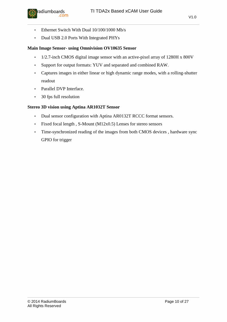
• Ethernet Switch With Dual 10/100/1000 Mb/s
• Dual USB 2.0 Ports With Integrated PHYs
Main Image Sensor- using Omnivision OV10635 Sensor
• 1/2.7-inch CMOS digital image sensor with an active-pixel array of 1280H x 800V
• Support for output formats: YUV and separated and combined RAW.
• Captures images in either linear or high dynamic range modes, with a rolling-shutter
readout
• Parallel DVP Interface.
• 30 fps full resolution
Stereo 3D vision using Aptina AR1032T Sensor
• Dual sensor configuration with Aptina AR0132T RCCC format sensors.
• Fixed focal length , S-Mount (M12x0.5) Lenses for stereo sensors
• Time-synchronized reading of the images from both CMOS devices , hardware sync
GPIO for trigger

© 2014 RadiumBoards Page 11 of 27 All Rights Reserved
TI TDA2x Based xCAM User Guide
V1.0
2.2 Technical Specifications
The following table provides the technical specifications of TDA2x xCAM Platform:
Items Description
Video Processor TI TDA2x Video Processor
Sensors • Main Image Sensor
• Stereo Sensor
Boot/Configuration • TDA2x- 256Mb QSPI Flash
Memory • TDA2x -1GB, 64-bit (four x16 devices)DDR3L
Networking • 10/100/1000 Base-TX with RJ-45 connectors
Video/Display • Standard HDMI Out
Audio • Line out (3.5mm) for external amplifier and speaker connection
Connectors
Back Panel Side Panel
• USB 3.0 micro B
• USB2.0 TYPE A
• Micro SD push –push with CD
• HDMI
• Power IN terminal block
• Gigabit Port (RJ 45)
• 7 Port terminal block for Alarm
/control or CAN interface
• Debug Port connector
Miscellaneous • RTC
Control and I/O
• USB 3.0 Device Interface
• USB 2.0 Host Interface
• SD Card
Debug Interfaces • JTAG
• Console
Power • 12V, DC adapter input
Status LED • Tri color LED for power /status indication
Table 3: Technical Specifications

© 2014 RadiumBoards Page 12 of 27 All Rights Reserved
TI TDA2x Based xCAM User Guide
V1.0
2.3 Hardware Overview
Each of the different boards available for the xCAM platform is shown below and may be
used for reference. Note the images are for representation only and may be slightly different
depending upon build and revision.
Figure 2:TDA2x Main Board

© 2014 RadiumBoards Page 13 of 27 All Rights Reserved
TI TDA2x Based xCAM User Guide
V1.0
Figure 3: Add On Interface Board
Figure 4: Main Image Sensor Board

© 2014 RadiumBoards Page 14 of 27 All Rights Reserved
TI TDA2x Based xCAM User Guide
V1.0
Figure 5: Stereo Board

© 2014 RadiumBoards Page 15 of 27 All Rights Reserved
TI TDA2x Based xCAM User Guide
V1.0
Figure 6: FPD Link Board
Figure 7: Power Board

© 2014 RadiumBoards Page 16 of 27 All Rights Reserved
TI TDA2x Based xCAM User Guide
V1.0
Figure 8 : Interface of Stereo with TDA2x Main Board

© 2014 RadiumBoards Page 17 of 27 All Rights Reserved
TI TDA2x Based xCAM User Guide
V1.0
Figure 9: Interface of Image Sensor with Add On Interface Board

© 2014 RadiumBoards Page 18 of 27 All Rights Reserved
TI TDA2x Based xCAM User Guide
V1.0
Table 4 below describes the various interfaces to the xCAM.
Interface Description
Camera Connector One pair of Stereo Sensor, one Image Sensor are present
on the front panel.
Ethernet Connector
Standard RJ-45 Ethernet connector for IP network
connection.
Power Input Power adapter connection. This is a +12V DC inlet, which
connects to an external power supply.
SD Card Holder For inserting the SD card to store data directly onto the
card and to support the booting of the Vayu board.
USB USB interface can be used to connect the Wi-Fi USB
Stick or USB 3G dongle
Alarm In
Alarm out
Two alarm ports – input and output available on the back
panel of the camera.
Debug Console Debug console is used for service and debugging
purposes.
HDMI A standard HDMI interface on back panel for streaming
video to HDTVs.
3.5mm Audio Jack An audio jack for listening and recording the voice
JTAG Connector JTAG connector for debugging and development
Table 4: xCAM Interface Description

© 2014 RadiumBoards Page 19 of 27 All Rights Reserved
TI TDA2x Based xCAM User Guide
V1.0
2.4 Internal Connections
This section describes internal connections of XCam.
As shown in below image, stereo sensor and image sensor board will be connected to
TDA2x main board by default.
Figure 10: Connection of Stereo and Image sensor to Main Board

© 2014 RadiumBoards Page 20 of 27 All Rights Reserved
TI TDA2x Based xCAM User Guide
V1.0
To enable FPD Link cams, FPD Link Board should be connected to TDA2x main board as
shown:
Figure 11: Connection of FPD link to Main Board
Figure 12: XCam with FPD Cams connection
© 2014 RadiumBoards Page 21 of 27 All Rights Reserved
TI TDA2x Based xCAM User Guide
V1.0
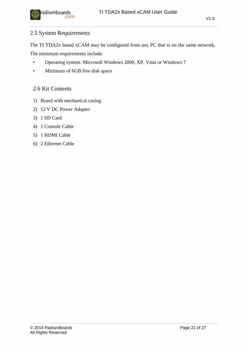
2.5 System Requirements
The TI TDA2x based xCAM may be configured from any PC that is on the same network.
The minimum requirements include:
• Operating system: Microsoft Windows 2000, XP, Vista or Windows 7
• Minimum of 6GB free disk space
2.6 Kit Contents
1) Board with mechanical casing
2) 12 V DC Power Adapter
3) 1 SD Card
4) 1 Console Cable
5) 1 HDMI Cable
6) 2 Ethernet Cable

© 2014 RadiumBoards Page 22 of 27 All Rights Reserved
TI TDA2x Based xCAM User Guide
V1.0
3. CAN Interface
There is a terminal block connector on left side of Main Board for CAN interface. CANH,
CANL and GND signals are shown as below:
Figure 13: CAN Interface connection

© 2014 RadiumBoards Page 23 of 27 All Rights Reserved
TI TDA2x Based xCAM User Guide
V1.0
4. ADAS Domain Use Cases
xCAM includes a full featured software development platform called Vision SDK
development kit. Vision Software Development Kit (Vision SDK) is a multi-processor
software development package for TI’s family of ADAS SoCs. The software framework
allows users to create different ADAS application data flows involving video capture, video
pre-processing, video analytics algorithms, and video display. The framework has sample
ADAS data flows which exercises different CPUs and HW accelerators in the ADAS SoC
and shows customer how to effectively use different sub-systems in the SoC. Frame work is
generic enough to plug in application specific algorithms in the system. The Vision SDK on
xCAM supports the following use-cases as examples:
• Stereo disparity processing flow
• Radar processing flow
• Image sensor processing flow
4.1 Stereo Disparity Processing Flow
The Fusion Camera's stereo board is enabled by two Aptina AR0132 RCCC sensors, which
deliver sharp, high definition images with great low-light and high dynamic range
performance as well as rapid capture up to 60 fps. With a baseline separation of 115mm and
the flexibility to attach a variety of optics that can provide field-of-views (FOVs) from 40
degrees (narrow) to 120 degree (fisheye).
The stereo module on Fusion Camera can be configured to support many different
applications that leverage depth information, including automatic emergency braking,
collision avoidance, obstacle detection, adaptive cruise control, and advanced park assist.

© 2014 RadiumBoards Page 24 of 27 All Rights Reserved
TI TDA2x Based xCAM User Guide
V1.0
Figure 14: Simplified Stereo processing flow hardware / software dataflow diagram
Some salient features for Stereo processing flow are:
Dual AR0132 RCCC sensor support
Hardware sensor synchronization
RCCC (CFA) ISP support
High performance Disparity processing algorithm implementation on DSP
4.2 Radar Processing Flow
xCAM allows connecting RADAR module via FPD LINK III to one of the on-board capture
interface. The simplified connectivity diagram is shown below:

© 2014 RadiumBoards Page 25 of 27 All Rights Reserved
TI TDA2x Based xCAM User Guide
V1.0
Figure 15: Simplified RADAR processing flow hardware/software dataflow diagram
Vision SDK will support framework for RADAR processing and output interpolation for
vision purpose.
4.3 Image Sensor Processing Flow
xCAM has facility for High quality color imaging. This functionality is provided by main
image sensor. Main image sensor is a 10 bit omnivision sensor having 720p resolution. It has
internal ISP (Image Signal Process) inbuilt. After image processing the data is routed to VIN
port of TDA2x processor. The moment someone selects the usecase from TDA2x console,
TDA2x captures the data through its VIN port and displays it on HDMI.

© 2014 RadiumBoards Page 26 of 27 All Rights Reserved
TI TDA2x Based xCAM User Guide
V1.0
Figure 16: Simplified Image Sensor processing flow hardware/software dataflow diagram
5. Mechanical Information
5.1 Dimension of Enclosure
The tentative camera front plate measurements are shown below:
Figure 17: Camera front plate measurements

© 2014 RadiumBoards Page 27 of 27 All Rights Reserved
TI TDA2x Based xCAM User Guide
V1.0
5.2 Enclosure Design
Enclosure has been designed not only for easy assembly/disassembly, but also easy for
internal connectivity.
The figure below shows the internal board to board connections. It shows how those sensors
and sensor boards are connected to their respective board.
Figure 18: Fusion Camera Internal Assembly View
TDA2x Main Board Vision Board Use Case
On-camera sensors use case Capture Interface
VIN 1A FPD Link (Radar) None
VIN 2A FPD Link 4 Image Sensor(OV10635)
VIN 3A FPD Link 3 None
VIN 5A FPD Link 1 Stereo Sensor 1 (AR0132)
VIN 6A FPD Link 2 Stereo Sensor 2 (AR0132)
Table 5 Configuration with/without vision adapter board