Thursday, May10, 2018
64
1 Thursday, May 10, 2018
Transcript of Thursday, May10, 2018

1Thursday, May 10, 2018

Comparative Design and Analysis of Post-Tension Concrete & Steel Bridges At Dhahran-Oqair-Salwa Road
Dammam To Old AbqaiqSENIOR PROJECT FALL 2018/2019 (FINAL-EXAMPRESENTATION)
Coordinator:Dr. Andi Asiz Advisors:
Date: December 25, 2018
Eng. Mohammed Nayeemuddin Dr. Tahar Ayadat
2December 25, 2018
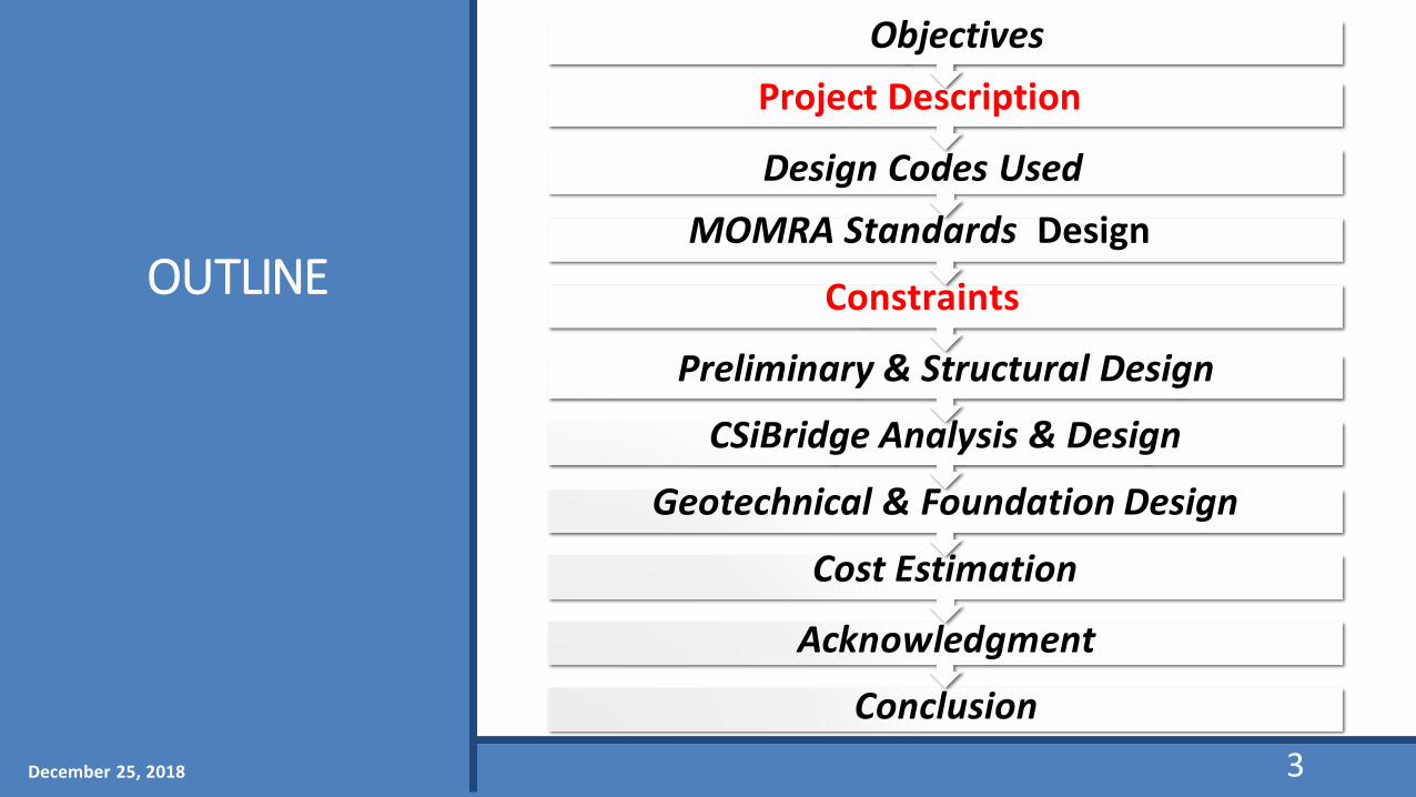
OUTLINE
Preliminary & Structural Design
CSiBridge Analysis & Design
Geotechnical & Foundation Design
Cost Estimation
Acknowledgment
Conclusion
Objectives
Project Description
Design Codes Used
MOMRA Standards Design
Constraints
3December 25, 2018

Ziad Al HarthiHamad Al Kaltham
Civil Engineering
Azzam Al Harthi Hisham Al Mousa201400009 201301153 201201648 201400827
4
Meet The Group
December 25, 2018

PROJECT OBJECTIVES
1
Structural Design Of The
BridgeFollowing AASHTO & MOMRA
Standards.
2
GeotechnicalDesign For
Piers & Foundation
System.
3
Cost Estimation compared with
the post-tensioned
bridge.
5December 25, 2018

PROJECTDESCRIPTION
Location: At Dhahran-Oqair-Salwa Road Dammam To Old Abqaiq
6December 25, 2018

Constraints
7December 25, 2018
1. Structural DesignAramco’s Piping SystemSpan (Deflection )HeightSpeed limitNumber of lanesWidthLoad Combinations
Type Constraint Solution
Pipes (Three) In the way Build a Bidge
Span (Two) Pipes Diameter Foundation size
Height Pipes/ Maintenance Height >3
Number of lane Highway (Freeway 120km/h)
>3

Constraints
8December 25, 2018
1. GeotechnicalChemical (Sulfate, Sulfer)Difficult Soil (Sabkha)Aramco’s Oil Piping SystemEnvironmental
Type Constraint Solution
Difficult soil Sabkha Driven Piles
Chemicals Sulfate, Sulfer(Sulfates 0.2%< 0.38% < 2.0 %)
Cement type V Coating
Environmental Chemicals Lane Fills
Pipes with Foundation
Pipes andFoundation Might be to close
Foundation Dimesions

PROJECT DESCRIPTION(continue)
Three traffic lanes
Two simply supported spans with 30 m inlength
60 m length16.5 m width
Two bent cap withheight of 3.5 m
9December 25, 2018

PROJECTDESCRIPTION(continue)
LAYOUT (FULL)
60m
10December 25, 2018

PROJECTDESCRIPTION(continue)
LAYOUT (TOP VIEW)
11December 25, 2018

PROJECTDESCRIPTION(continue)
LAYOUT (SIDE VIEW)
Super-structure (Asphalt, Concrete slab,Girders)
Abutment
Pier
Pier Cap
Bearing
Foundation
12December 25, 2018

PROJECT DESCRIPTION(continue)
STEEL BRIDGE CROSS SECTION
Steel Girder
13December 25, 2018

PROJECTDESCRIPTION (Continue)
POST-TENSION BRIDGE CROSS SECTION
Steel Girder
14December 25, 2018
Design Codes Used
(MOMRA) Ministry of Municipal and Rural Affairs.(AASHTO) American Association of State Highway and Transportation Official.(AISC) American Institute of Steel Construction.(ACI) American Concrete Institute.
15December 25, 2018

MOMRA Standards (Post-Tension )
Standard Limitation
Safety Factors 1.3 Dead, 1.6 Moving
Asphalt thickness 75 mm
Concrete slab thickness 𝟐𝟎𝟎𝐦𝐦
Traffic Parapet H= 810 mm , W= 430 mm
Deflection limitL
800Precast I-Girder Depth ≥ 0.045 L
Compressive Strength of Concrete 𝒇𝒄′
28 MPa
Yielding strength of steel 𝒇𝒚 420 MPa
*L : Length of span *C: Concrete cover for slab thickness 16December 25, 2018

MOMRA Standards (Steel ) Standard Limitation
Safety Factors 1.3 Dead, 1.6 Moving
Asphalt thickness 75 mm
Concrete slab thickness 175mm
Traffic Parapet H= 810 mm , W= 430 mm
Deflection limitL
800
I-Girder Depth ≥ 0.040 L
Compressive Strength of Concrete 𝒇𝒄′
28 MPa
Yielding strength of steel 𝒇𝒚 450 MPa
17*L : Length of span *C: Concrete cover for slab thickness December 25, 2018

Type of Load Result
Dead Load 36.34 KN/m
Truck Load 324.13KN
Lane Load 100.50 KN
Seismic Load 1018.75 KN
Wind Load 48.93KN
STAGE 1 Loads Calculation for Post-Tension (AASHTO)
18*Note: these loads are acting on one span. December 25, 2018

Type of Load Result
Dead Load 29.58 KN/m
Truck Load 334.13KN
Lane Load 100.5 KN
Seismic Load 895.35 KN
Wind Load 48.93 KN
STAGE 1 Loads Calculation for Steel (AASHTO)
19*Note: these loads are acting on one span. December 25, 2018

Reinforced Concrete Slab
Maximum Moment = 82.982 KN-m (From CSIBridge )
For each 1m×1m use:
5 # 16 mm
STAGE 2 Super Structure for Post-Tension
20December 25, 2018

Reinforced Concrete Slab
Maximum Moment = 80.25 KN-m (From CSI Bridge)
For each 1m×1m use:
5 # 16 mm
STAGE 2 Super Structure for Steel
21December 25, 2018

Precast I-Girder (MOMRA)
STAGE 2Super Structure post-tension (Continue)
Properties Data
Gross Area 0.765m2
Moment of Inertia 0.231 m4
Depth 1.5 m
Strand Grade 270 (1860 Mpa)
Self-weight 18.298 KN/m
Strand Force 1796.96 KN
Number of Strands 6 strands
Diameter of Strands 0.01524 m
Reinforcement strength 𝒇𝒚
420 MPa
22December 25, 2018

Steel Girder (MOMRA)
STAGE 2 Super Structure steel (Continue)
Properties Data
Gross Area 0.16064484 m2
Moment of Inertia 0.0015 m4
Depth 1.0795 m
Width 0.45974 m
Self-weight 12.611 kN/m
Yielding strength 𝒇𝒚 450 Mpa
23December 25, 2018

Checking for Steel Girder (MOMRA)
STAGE 2 Super Structure (Continue)
ShearVu = 8403.55 KN < ∅Vn = 20639.84
KN
Moment Mu = 8287.75 KN-m <∅M = 79951.07
KN-m
Deflection 33.30 mm < 37.50 mm
Depth of steel
1.0795 m ≥ 1m
Moment of Inertia
0.02805 m4 ≥ 0.0015 m4
24
24December 25, 2018

Losses Of Pre-stress For Post-tension 1- Loss due to Elastic Shortening
2- Loss due to Shrinkage of Concrete ∆𝒇pSR =𝜺bid 𝑬P 𝑲id
3- Loss due to Creep of Concrete ∆𝒇pCR=
𝑬𝒑
𝑬𝒄𝒊× 𝒇cgp × 𝝍 (td , tt ) 𝑲id
4- Loss due to Creep in steel (Relaxation of steel)
5- The losses due to friction ∆𝒑µ(x) =𝒑max (𝟏 − 𝒆-µ (Ɵ+Kx))
25December 25, 2018

Losses of pre-stress for post-tension concrete
1- Loss due to Elastic Shortening [ 6.7% ]
2- Loss due to Shrinkage of Concrete [ 2.1 % ]
3- Loss due to Creep of Concrete [ 2.9 % ]
4- Loss due to Creep in steel (Relaxation of steel) [ 2.3 % ]
5- The losses due to friction [ 3.0% ]
Total percentage for losses is 17 %
26December 25, 2018

27December 25, 2018

PRELIMINARY & STRUCTURAL DESIGN (continue)
Bracing (AISC -Manual of Steel Construction, L3 x 3 x 1/2)
Maximum unbraced length Lp = 5 m
Lateral Load = 30% of reaction
Section: 𝐿3 × 3 × 1/2
Bracing Design
28December 25, 2018

Bearing Bearings are elements transferring vertical loads from Superstructure to
Substructure.
http://www.archiexpo.com/prod/mageba/product-126411-1333289.html
29December 25, 2018
Sub-StructureSTAGE 3

Steel-Reinforced Elastomeric Bearing (AASHTO)
Suited for bridges with small lengths (less than 40 m)
30
BearingDesign
December 25, 2018
Length = 300 mm
Width = 400 mm
The Total Thickness=84.4 mm
Sub-Structure Steel (Continue)STAGE 3
31December 25, 2018
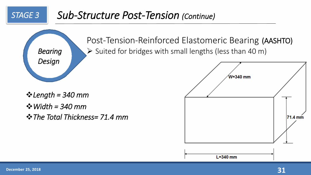
Sub-Structure Post-Tension (Continue)
BearingDesign
Length = 340 mm
Width = 340 mm
The Total Thickness= 71.4 mm
Post-Tension-Reinforced Elastomeric Bearing (AASHTO)
Suited for bridges with small lengths (less than 40 m)
STAGE 3

0.75m 5.7m 5.7m 0.75m
1.2m 1.2m1.2m
16.5m
December 25, 2018
Sub-Structure Steel (Continue)
32
Pier CapDesign
W= (1.2)(1.5)(23.92) = 43.056 KN/mWu= (43.056)(1.2) = 51.667 KN/m
STAGE 3

From CSIBridge:Mmax = -1360.13 KN.mMmax = 1207.72 KN.mVmax = 2690.26 KNR = 5969 KN
December 25, 2018
Sub-Structure Steel (Continue)
Pier CapDesign
33
1127.63 KN
STAGE 3

Pier CapDesign
December 25, 2018 34
Sub-Structure Steel (Continue)
6 # 25 mm bars for top6 # 25 mm bars for bottom12 mm for stirrupS = 42 mm
STAGE 3

W= (1.5)(1.2)(23.92) = 43.056 KN/mWu= (43.056)(1.2) = 51.667 KN/m
35December 25, 2018
Pier CapDesign
Sub-Structure Post-Tension (Continue)STAGE 3
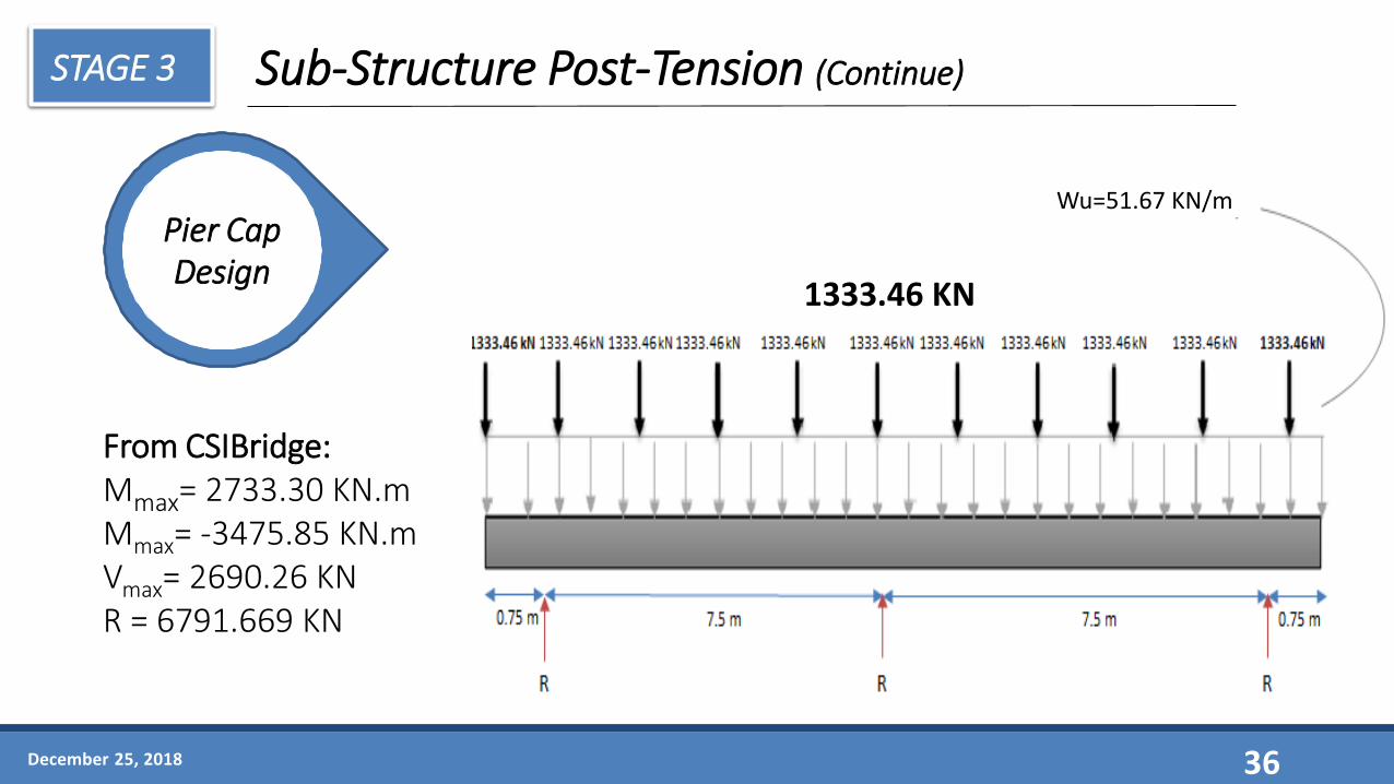
From CSIBridge:Mmax= 2733.30 KN.mMmax= -3475.85 KN.mVmax= 2690.26 KNR = 6791.669 KN
Wu=51.67 KN/m
36
1333.46 KN
December 25, 2018
Sub-Structure Post-Tension (Continue)
Pier CapDesign
STAGE 3

Sub-Structure Post-Tension (Continue)
December 25, 2018
Pier CapDesign
37
14 # 25 mm bars for top10 # 25 mm bars for bottom12 mm for stirrupS = 95 mm
STAGE 3

Total height is 3.5 m
Axial Compression: → P = 5969 KN (From CSI-Bridge)
Wind & Earthquake moment :→ M = 3133.725 + 116.33 = 3250.057 KN-m
38
PiersDesign
PRELIMINARY & STRUCTURAL DESIGN for Steel (continue)
December 25, 2018

Use 77 ϕ 20 mm bar
39
PRELIMINARY & STRUCTURAL DESIGN for Steel (continue)
PiersDesign
December 25, 2018

Axial Compression:→ P = 6791.669 KN (From CSI-Bridge)
Wind & Earthquake moment:→ M = 3565.625 + 119= 3684.625 KN-m
40
PiersDesign
PRELIMINARY & STRUCTURAL DESIGN for Post-Tension (continue)
December 25, 2018
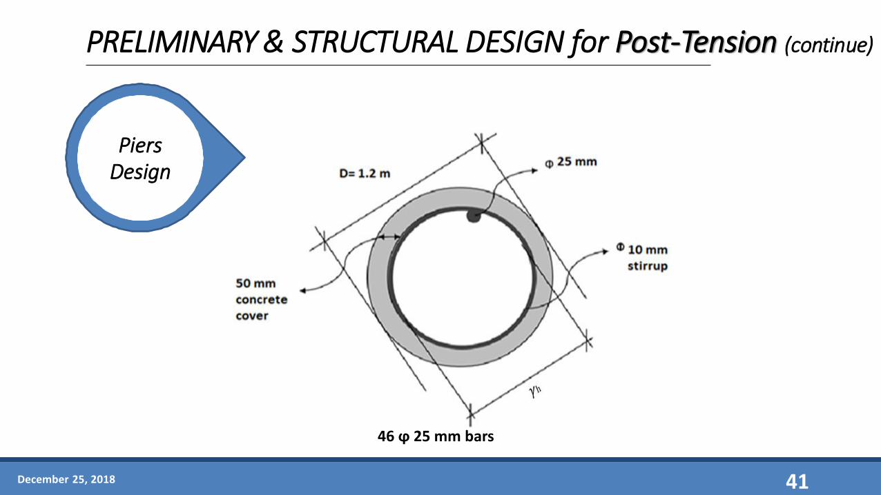
46 ϕ 25 mm bars
41
PRELIMINARY & STRUCTURAL DESIGN for Post-Tension (continue)
PiersDesign
December 25, 2018

CSiBridge ANALYSIS &DESIGN for Steel
Steel 3D MODEL
42December 25, 2018

43
CSiBridge ANALYSIS &DESIGN for Steel (continue)
DEFLECTION
Allowable Deflection : L
800= 37.5 mm (MOMRA)
The Software Result = 28.8 mm
December 25, 2018

Maximum Moment = 25418.796 kN-m (AISC)
Software Result = 32991.34kN-m
44
CSiBridge ANALYSIS &DESIGN for Steel (continue)
MOMENT
December 25, 2018

Maximum Shear = 20639.84 KN (AISC)
Software Result = 11,277.495 kN
45
CSiBridge ANALYSIS &DESIGN for Steel (continue)
SHEAR
December 25, 2018

46
CSiBridge ANALYSIS &DESIGN for Post-Tension Concrete
Post-Tension Concrete 3D MODEL
December 25, 2018

47
CSiBridge ANALYSIS &DESIGN for Post-Tension Concrete (continue)
DEFLECTION
Allowable Deflection : L
800= 37.5 mm (MOMRA)
The Software Result = 25.96 mm
December 25, 2018

48
CSiBridge ANALYSIS &DESIGN for Post-Tension Concrete (continue)
MOMENT
Maximum Moment = 27915.61 kN-m (AISC)
Software Result = 19915.602 kN-m
December 25, 2018

49
CSiBridge ANALYSIS &DESIGN for Post-Tension Concrete (continue)
SHEAR
Maximum Shear = 16951 KN (AISC)
Software Result = 5853.26 kN
December 25, 2018

Site Investigation
Soil Profile
Foundation System
GEOTECHNICAL & FOUNDATION DESIGN
December 25, 2018 50

GEOTECHNICAL & FOUNDATION DESIGN (continue)
Site Investigation
December 25, 2018 51

Soil Profile
December 25, 2018 52
GEOTECHNICAL & FOUNDATION DESIGN (continue)

Foundation System Characteristics Results
Formula used Rock Formula
Rock QualityDesignation (R.Q.D)
50 %
Rock Capacity (RC) 30.00 MPa
Allowable Bearing Capacity (qall)
120 kN/m2
GEOTECHNICAL & FOUNDATION DESIGN(continue)
Final Design (strip footing)
Foundation System (Section B)
Characteristics Result
Formula used Meyerhof
Angle of friction (∅) 35°
Unit weight (𝜸) 20 kN/m3
Cohesion factor (C) 0
Factor of Safety (FS) 3
Allowable Bearing Capacity (qall) 170.90 kN/m2
Maximum Bearing Capacity (qmax) 139.21 kN/m2
Settlement (Se) 3.4 mm < 16 mm
30Thursday, May 10, 2018
December 25, 2018 53
GEOTECHNICAL & FOUNDATION DESIGN (continue)
Steel

Foundation System Characteristics Results
Formula used Terzaghi formula
Angel of Friction (∅) 35°
Unit Weight (γ) 20 kN/m3
Cohesion Factor (C) 0
Allowable Bearing Capacity (qall)
1286.71 KN/m2
Maximum Bearing Capacity (qmax)
5564.82 kN/m2
GEOTECHNICAL & FOUNDATION DESIGN(continue)
Final Design (strip footing)
Foundation System (Section B)
Characteristics Result
Formula used Meyerhof
Angle of friction (∅) 35°
Unit weight (𝜸) 20 kN/m3
Cohesion factor (C) 0
Factor of Safety (FS) 3
Allowable Bearing Capacity (qall) 170.90 kN/m2
Maximum Bearing Capacity (qmax) 139.21 kN/m2
Settlement (Se) 3.4 mm < 16 mm
30Thursday, May 10, 2018
Steel
December 25, 2018 54
GEOTECHNICAL & FOUNDATION DESIGN (continue)

Foundation System Characteristics Results
Formula used Rock Formula
Rock QualityDesignation (R.Q.D)
50 %
Rock Capacity (RC) 30.00 MPa
Allowable Bearing Capacity (qall)
120 kN/m2
GEOTECHNICAL & FOUNDATION DESIGN(continue)
Final Design (strip footing)
Foundation System (Section B)
Characteristics Result
Formula used Meyerhof
Angle of friction (∅) 35°
Unit weight (𝜸) 20 kN/m3
Cohesion factor (C) 0
Factor of Safety (FS) 3
Allowable Bearing Capacity (qall) 170.90 kN/m2
Maximum Bearing Capacity (qmax) 139.21 kN/m2
Settlement (Se) 3.4 mm < 16 mm
30Thursday, May 10, 2018
Post-Tensioned Concrete
December 25, 2018 55
GEOTECHNICAL & FOUNDATION DESIGN (continue)

Foundation System Characteristics Results
Formula used Terzaghi Formula
Angel of Friction (∅) 35°
Unit Weight (γ) 20 kN/m3
Cohesion Factor (C) 0
Allowable Bearing Capacity (qall)
1359.36 KN/m2
Maximum Bearing Capacity (qmax)
6314.437 kN/m2
GEOTECHNICAL & FOUNDATION DESIGN(continue)
Final Design (strip footing)
Foundation System (Section B)
Characteristics Result
Formula used Meyerhof
Angle of friction (∅) 35°
Unit weight (𝜸) 20 kN/m3
Cohesion factor (C) 0
Factor of Safety (FS) 3
Allowable Bearing Capacity (qall) 170.90 kN/m2
Maximum Bearing Capacity (qmax) 139.21 kN/m2
Settlement (Se) 3.4 mm < 16 mm
30Thursday, May 10, 2018
December 25, 2018 56
GEOTECHNICAL & FOUNDATION DESIGN (continue)
Post-Tensioned Concrete

COST ESTIMATION
Steel
Analogous Technique:
Compared with king Salman Steel Bridge Intersection with King Fahad Road.
December 25, 2018 57

COST ESTIMATION
Steel
Analogous Technique:
Cost of new project= (Cost of the old project x S.F x A.F x L.F x T.F x Q.F) + overhead risk.
The Total Cost = 28,324,421.35 SAR
December 25, 2018 58

COST ESTIMATION
Analogous Technique:
Prince Naif Concrete Bridge Intersection with King Fahad Road.
December 25, 2018 59
Post-Tensioned Concrete
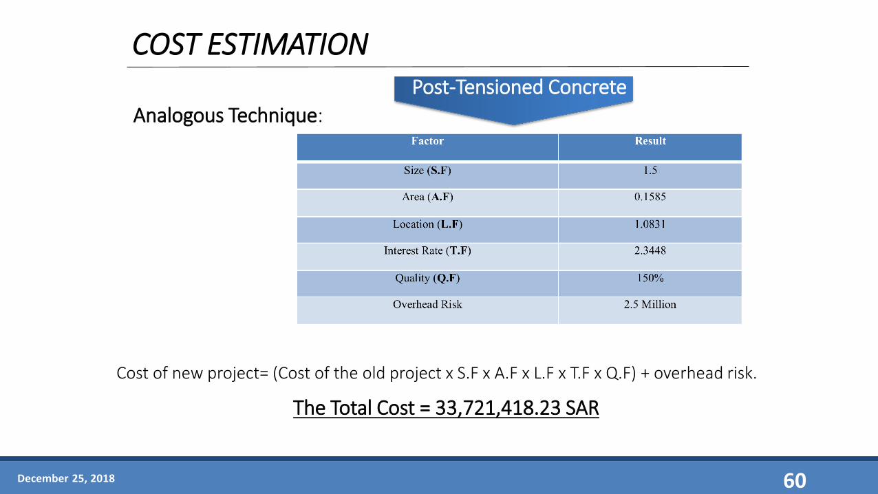
COST ESTIMATION
Analogous Technique:
Cost of new project= (Cost of the old project x S.F x A.F x L.F x T.F x Q.F) + overhead risk.
Post-Tensioned Concrete
The Total Cost = 33,721,418.23 SAR
December 25, 2018 60

ACKNOWLEDGMENT
Dr. ANDI ASIZCoordinator
Dr. TAHAR AYADATAdvisor
Dr. Saidur ChowdhuryConsultant
Eng. MOHD NAYEEMUDDIN Advisor
Eng. DANISH AHMED Consultant
December 25, 2018 61

CONCLUSION
Structural Design of The Bridges Following AASHTO & MOMRA Standards.
Geotechnical Design for Foundation System.
Modeling Using Csibridge Software & Analysis.
Cost Estimation of Steel & Post-tensioned Concrete Bridges ( Steel Bridge Cheaper).
December 25, 2018 62

REFERENCES
Civil Engineering. (2015, January 21). What Is a Girder Bridge? Retrieved February 2, 2018, from https://goo.gl/FYYK • Hewson, N. R. (2012). Prestressed concrete bridges: Design and construction. London: ICE.• State-of-the-art report on high-strength concrete. (1994). Farmington Hills, MI: American Concrete Institute.• AASHTO: Catalyst for transportation excellence. (2001). Washington, D.C: AASHTO.• MOMRA: Ministry of municipal & Rural Affairs Deputy Ministry for Technical Affairs. (2013). Kingdom of Saudi Arabia: MOMRA.• Mahmoud, K. M. (2003). Recent Developments in Bridge Engineering. Tokyo: A.A. Balkema.• Amlan, K.S.& Devdas,M.(2000). Prestressed Concrete Structures. Indian: from
https://nptel.ac.in/courses/105106117/pdf/2_Losses_in_Prestress/Section2.1.pdf• Nilson, A.H.(1978). DESIGN OF PRESTRESSED CONCRETE.United States: Hoboken.• Antoine E. N.(2012). PRESTRESSED CONCRETE ANALYSIS AND DESIGN: FUNDAMENTALS.University of Michigan: Ann Arbor.• Ghali, R. Favre, M. Elbadry.(2002). Stresses and Deformations: Analysis and Design for Serviceability. London.• AlDubaikel.F, AlAzeb.M & Ratrout.F.(2018). Design of Post-Tensioned Concrete Bridge At Prince Metib Service Road Intersection
with Railway in Dammam.Saudi Arabia: Khobar.• Al-Hajri.S , Al-Hajri.A & Al-Sharif.A.(2018). Design a Steel Bridge at Prince Metib Service Roads Intersection with Railway In
Dammam. Saudi Arabia: Khobar.
• MOMRA
• AASHTO
December 25, 2018 63

Thank you
Q & A
December 25, 2018 64