Three-way Secure Card Reader Authenticators Installation ...
69
MagTek I 1710 Apollo Court I Seal Beach, CA 90740 I Phone: (562) 546-6400 I Technical Support: (888) 624-8350 www.magtek.com DynaFlex Family of Products Three-way Secure Card Reader Authenticators Installation and Operation Manual January 2022 Document Number: D998200382-30 REGISTERED TO ISO 9001:2015
Transcript of Three-way Secure Card Reader Authenticators Installation ...
MagTek I 1710 Apollo Court I Seal Beach, CA 90740 I Phone: (562) 546-6400 I Technical Support: (888) 624-8350 www.magtek.com
DynaFlex Family of Products Three-way Secure Card Reader Authenticators
Installation and Operation Manual
January 2022
Document Number: D998200382-30
REGISTERED TO ISO 9001:2015

DynaFlex Family of Products| Three-way Secure Card Reader Authenticators | Installation and Operation Manual
Page 2 of 69 (D998200382-30)
Copyright © 2006 - 2022 MagTek, Inc. Printed in the United States of America
INFORMATION IN THIS PUBLICATION IS SUBJECT TO CHANGE WITHOUT NOTICE AND MAY CONTAIN TECHNICAL INACCURACIES OR GRAPHICAL DISCREPANCIES. CHANGES OR IMPROVEMENTS MADE TO THIS PRODUCT WILL BE UPDATED IN THE NEXT PUBLICATION RELEASE. NO PART OF THIS DOCUMENT MAY BE REPRODUCED OR TRANSMITTED IN ANY FORM OR BY ANY MEANS, ELECTRONIC OR MECHANICAL, FOR ANY PURPOSE, WITHOUT THE EXPRESS WRITTEN PERMISSION OF MAGTEK, INC. SOME FEATURES AND FUNCTIONS MAY BE DOCUMENTED, BUT NOT AVAILABLE WITH THE CURRENT RELEASE OF THE PRODUCT. PLEASE CONTACT YOUR MAGTEK REPRESENTATIVE FOR QUESTIONS ABOUT SPECIFIC FEATURES AND FUNCTIONS AND WHEN THEY ARE SCHEDULED TO BECOME AVAILABLE. MagTek®, MagnePrint®, and MagneSafe® are registered trademarks of MagTek, Inc. Magensa™ is a trademark of MagTek, Inc. AAMVA™ is a trademark of AAMVA. American Express® and EXPRESSPAY FROM AMERICAN EXPRESS® are registered trademarks of American Express Marketing & Development Corp. D-PAYMENT APPLICATION SPECIFICATION® is a registered trademark to Discover Financial Services CORPORATION MasterCard® is a registered trademark and PayPass™ and Tap & Go™ are trademarks of MasterCard International Incorporated. Visa® and Visa payWave® are registered trademarks of Visa International Service Association. ANSI®, the ANSI logo, and numerous other identifiers containing "ANSI" are registered trademarks, service marks, and accreditation marks of the American National Standards Institute (ANSI). ISO® is a registered trademark of the International Organization for Standardization. UL™ and the UL logo are trademarks of UL LLC. PCI Security Standards Council® is a registered trademark of the PCI Security Standards Council, LLC. EMV® is a registered trademark in the U.S. and other countries and an unregistered trademark elsewhere. The EMV trademark is owned by EMVCo, LLC. The Contactless Indicator mark, consisting of four graduating arcs, is a trademark owned by and used with permission of EMVCo, LLC. The Bluetooth® word mark and logos are registered trademarks owned by Bluetooth SIG, Inc. and any use of such marks by MagTek is under license. Google Play™ store, Google Wallet™ payment service, and Android™ platform are trademarks of Google Inc. Apple Pay®, iPhone®, iPod®, Mac®, and OS X® are registered trademarks of Apple Inc., registered in the U.S. and other countries. iPad™ is a trademark of Apple. Inc. App StoreSM is a service mark of Apple Inc., registered in the U.S. and other countries. IOS is a trademark or registered trademark of Cisco in the U.S. and other countries and is used by Apple Inc. under license. Microsoft®, Windows®, and .NET® are registered trademarks of Microsoft Corporation. All other system names and product names are the property of their respective owners.
DynaFlex Family of Products| Three-way Secure Card Reader Authenticators | Installation and Operation Manual
Page 3 of 69 (D998200382-30)
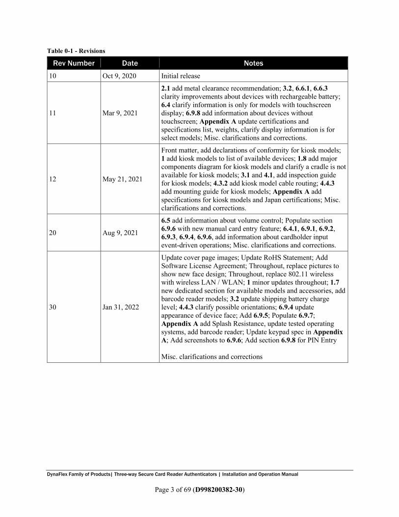
Table 0-1 - Revisions
Rev Number Date Notes
10 Oct 9, 2020 Initial release
11 Mar 9, 2021
2.1 add metal clearance recommendation; 3.2, 6.6.1, 6.6.3 clarity improvements about devices with rechargeable battery; 6.4 clarify information is only for models with touchscreen display; 6.9.8 add information about devices without touchscreen; Appendix A update certifications and specifications list, weights, clarify display information is for select models; Misc. clarifications and corrections.
12 May 21, 2021
Front matter, add declarations of conformity for kiosk models; 1 add kiosk models to list of available devices; 1.8 add major components diagram for kiosk models and clarify a cradle is not available for kiosk models; 3.1 and 4.1, add inspection guide for kiosk models; 4.3.2 add kiosk model cable routing; 4.4.3 add mounting guide for kiosk models; Appendix A add specifications for kiosk models and Japan certifications; Misc. clarifications and corrections.
20 Aug 9, 2021
6.5 add information about volume control; Populate section 6.9.6 with new manual card entry feature; 6.4.1, 6.9.1, 6.9.2, 6.9.3, 6.9.4, 6.9.6, add information about cardholder input event-driven operations; Misc. clarifications and corrections.
30 Jan 31, 2022
Update cover page images; Update RoHS Statement; Add Software License Agreement; Throughout, replace pictures to show new face design; Throughout, replace 802.11 wireless with wireless LAN / WLAN; 1 minor updates throughout; 1.7 new dedicated section for available models and accessories, add barcode reader models; 3.2 update shipping battery charge level; 4.4.3 clarify possible orientations; 6.9.4 update appearance of device face; Add 6.9.5; Populate 6.9.7; Appendix A add Splash Resistance, update tested operating systems, add barcode reader; Update keypad spec in Appendix A; Add screenshots to 6.9.6; Add section 6.9.8 for PIN Entry Misc. clarifications and corrections

DynaFlex Family of Products| Three-way Secure Card Reader Authenticators | Installation and Operation Manual
Page 4 of 69 (D998200382-30)
LIMITED WARRANTY MagTek warrants that the products sold pursuant to this Agreement will perform in accordance with MagTek’s published specifications. This warranty shall be provided only for a period of one year from the date of the shipment of the product from MagTek (the “Warranty Period”). This warranty shall apply only to the “Buyer” (the original purchaser, unless that entity resells the product as authorized by MagTek, in which event this warranty shall apply only to the first repurchaser). During the Warranty Period, should this product fail to conform to MagTek’s specifications, MagTek will, at its option, repair or replace this product at no additional charge except as set forth below. Repair parts and replacement products will be furnished on an exchange basis and will be either reconditioned or new. All replaced parts and products become the property of MagTek. This limited warranty does not include service to repair damage to the product resulting from accident, disaster, unreasonable use, misuse, abuse, negligence, or modification of the product not authorized by MagTek. MagTek reserves the right to examine the alleged defective goods to determine whether the warranty is applicable. Without limiting the generality of the foregoing, MagTek specifically disclaims any liability or warranty for goods resold in other than MagTek’s original packages, and for goods modified, altered, or treated without authorization by MagTek. Service may be obtained by delivering the product during the warranty period to MagTek (1710 Apollo Court, Seal Beach, CA 90740). If this product is delivered by mail or by an equivalent shipping carrier, the customer agrees to insure the product or assume the risk of loss or damage in transit, to prepay shipping charges to the warranty service location, and to use the original shipping container or equivalent. MagTek will return the product, prepaid, via a three (3) day shipping service. A Return Material Authorization (“RMA”) number must accompany all returns. Buyers may obtain an RMA number by contacting MagTek Support Services at (888) 624-8350. EACH BUYER UNDERSTANDS THAT THIS MAGTEK PRODUCT IS OFFERED AS-IS. MAGTEK MAKES NO OTHER WARRANTY, EXPRESS OR IMPLIED, AND MAGTEK DISCLAIMS ANY WARRANTY OF ANY OTHER KIND, INCLUDING ANY WARRANTY OF MERCHANTABILITY OR FITNESS FOR A PARTICULAR PURPOSE. IF THIS PRODUCT DOES NOT CONFORM TO MAGTEK’S SPECIFICATIONS, THE SOLE REMEDY SHALL BE REPAIR OR REPLACEMENT AS PROVIDED ABOVE. MAGTEK’S LIABILITY, IF ANY, SHALL IN NO EVENT EXCEED THE TOTAL AMOUNT PAID TO MAGTEK UNDER THIS AGREEMENT. IN NO EVENT WILL MAGTEK BE LIABLE TO THE BUYER FOR ANY DAMAGES, INCLUDING ANY LOST PROFITS, LOST SAVINGS, OR OTHER INCIDENTAL OR CONSEQUENTIAL DAMAGES ARISING OUT OF THE USE OF, OR INABILITY TO USE, SUCH PRODUCT, EVEN IF MAGTEK HAS BEEN ADVISED OF THE POSSIBILITY OF SUCH DAMAGES, OR FOR ANY CLAIM BY ANY OTHER PARTY.

DynaFlex Family of Products| Three-way Secure Card Reader Authenticators | Installation and Operation Manual
Page 5 of 69 (D998200382-30)
LIMITATION ON LIABILITY EXCEPT AS PROVIDED IN THE SECTIONS RELATING TO MAGTEK’S LIMITED WARRANTY, MAGTEK’S LIABILITY UNDER THIS AGREEMENT IS LIMITED TO THE CONTRACT PRICE OF THIS PRODUCT. MAGTEK MAKES NO OTHER WARRANTIES WITH RESPECT TO THE PRODUCT, EXPRESSED OR IMPLIED, EXCEPT AS MAY BE STATED IN THIS AGREEMENT, AND MAGTEK DISCLAIMS ANY IMPLIED WARRANTY, INCLUDING WITHOUT LIMITATION ANY IMPLIED WARRANTY OF MERCHANTABILITY OR FITNESS FOR A PARTICULAR PURPOSE. MAGTEK SHALL NOT BE LIABLE FOR CONTINGENT, INCIDENTAL, OR CONSEQUENTIAL DAMAGES TO PERSONS OR PROPERTY. MAGTEK FURTHER LIMITS ITS LIABILITY OF ANY KIND WITH RESPECT TO THE PRODUCT, INCLUDING NEGLIGENCE ON ITS PART, TO THE CONTRACT PRICE FOR THE GOODS. MAGTEK’S SOLE LIABILITY AND BUYER’S EXCLUSIVE REMEDIES ARE STATED IN THIS SECTION AND IN THE SECTION RELATING TO MAGTEK’S LIMITED WARRANTY.

DynaFlex Family of Products| Three-way Secure Card Reader Authenticators | Installation and Operation Manual
Page 6 of 69 (D998200382-30)
FCC INFORMATION This device complies with Part 15 of the FCC Rules. Operation is subject to the following two conditions: (1) This device may not cause harmful interference, and (2) This device must accept any interference received, including interference that may cause undesired operation. Note: This equipment has been tested and found to comply with the limits for a Class B digital device, pursuant to part 15 of the FCC Rules. These limits are designed to provide reasonable protection against harmful interference in a residential installation. This equipment generates, uses and can radiate radio frequency energy and, if not installed and used in accordance with the instructions, may cause harmful interference to radio communications. However, there is no guarantee that interference will not occur in a particular installation. If this equipment does cause harmful interference to radio or television reception, which can be determined by turning the equipment off and on, the user is encouraged to try to correct the interference by one or more of the following measures: • Reorient or relocate the receiving antenna. • Increase the separation between the equipment and receiver. • Connect the equipment into an outlet on a circuit different from that to which the receiver is
connected. • Consult the dealer or an experienced radio/TV technician for help. Caution: Changes or modifications not expressly approved by MagTek could void the user’s authority to operate this equipment.
CANADIAN DECLARATION OF CONFORMITY This digital apparatus does not exceed the Class B limits for radio noise from digital apparatus set out in the Radio Interference Regulations of the Canadian Department of Communications. Le présent appareil numérique n’émet pas de bruits radioélectriques dépassant les limites applicables aux appareils numériques de la classe B prescrites dans le Réglement sur le brouillage radioélectrique édicté par le ministère des Communications du Canada. This Class B digital apparatus complies with Canadian ICES-003. Cet appareil numérique de la classe B est conformé à la norme NMB-003 du Canada.
INNOVATION, SCIENCE AND ECONOMIC DEVELOPEMENT CANADA (ISED)
This device complies with ISED Canada licence-exempt RSS standard(s). Operation is subject to the following two conditions: (1) This device may not cause interference, and (2) This device must accept any interference, including interference that may cause undesired operation of the device. Le présent appareil est conforme aux CNR d'Industrie Canada applicables aux appareils radio exempts de licence. L'exploitation est autorisée aux deux conditions suivantes: (1) L'appareil ne doit pas produire de brouillage, et (2) L'utilisateur de l'appareil doit accepter tout brouillage radioélectrique subi, même si le brouillage est susceptible d'en compromettre le fonctionnement.
CE STANDARDS Testing for compliance with CE requirements was performed by an independent laboratory. The unit under test was found compliant with standards established for Class B devices.

DynaFlex Family of Products| Three-way Secure Card Reader Authenticators | Installation and Operation Manual
Page 7 of 69 (D998200382-30)
EU STATEMENT Hereby, MagTek Inc. declares that the radio equipment types Wideband Transmission System (Wireless LAN and Bluetooth Low Energy), and Non-Specific Short Range Device (contactless) are in compliance with Directive 2014/53/EU. The full text of the EU declarations of conformity is available at the following internet addresses: • https://www.magtek.com/Content/DocumentationFiles/D998200404.pdf for DynaFlex with no
display, USB connection • https://www.magtek.com/Content/DocumentationFiles/D998200410.pdf for DynaFlex with no
display, Bluetooth LE connection • https://www.magtek.com/Content/DocumentationFiles/D998200411.pdf for DynaFlex Pro with USB
connection • https://www.magtek.com/Content/DocumentationFiles/D998200412.pdf for DynaFlex Pro with
Bluetooth LE connection • https://www.magtek.com/Content/DocumentationFiles/D998200413.pdf for DynaFlex Pro with
WLAN connection
UKCA STATEMENT Hereby, MagTek Inc. declares that the radio equipment types Wideband Transmission System (Wireless LAN and Bluetooth Low Energy), and Non-Specific Short Range Device (contactless) are in compliance with Radio Equipment Regulations 2017 Directive S.I.2017:1206. The full text of the UKCA declarations of conformity is available at the following internet addresses: • https://www.magtek.com/Content/DocumentationFiles/D998200475.pdf for DynaFlex with no
display, USB connection • https://www.magtek.com/Content/DocumentationFiles/D998200476.pdf for DynaFlex with no
display, Bluetooth LE connection • https://www.magtek.com/Content/DocumentationFiles/D998200477.pdf for DynaFlex Pro with USB
connection • https://www.magtek.com/Content/DocumentationFiles/D998200478.pdf for DynaFlex Pro with
Bluetooth LE connection • https://www.magtek.com/Content/DocumentationFiles/D998200479.pdf for DynaFlex Pro with
WLAN connection
AUSTRALIA / NEW ZEALAND STATEMENT Testing for compliance with AS/NZS standards was performed by a registered and accredited laboratory. The unit under test was found compliant with standards established under AS/NZS CISPR 32 (2013), AS/NZS 4268 Table 1, Row 59 DTS 2400-2483MHz SRD (802.11), and AS/NZS 4268 (2017) Table 1, Row 43 13.553-13.567MHz (contactless reader).
UL/CSA This product is recognized per UL 60950-1, 2nd Edition, 2011-12-19 (Information Technology Equipment - Safety - Part 1: General Requirements), CSA C22.2 No. 60950-1-07, 2nd Edition, 2011-12 (Information Technology Equipment - Safety - Part 1: General Requirements).
DynaFlex Family of Products| Three-way Secure Card Reader Authenticators | Installation and Operation Manual
Page 8 of 69 (D998200382-30)
ROHS STATEMENT When ordered as RoHS compliant, this product meets the Electrical and Electronic Equipment (EEE) Reduction of Hazardous Substances (RoHS) Directive (EU) 2015/863 amending Annex II to Directive 2011/65/EU. The marking is clearly recognizable, either as written words like “Pb-free,” “lead-free,” or as another clear symbol ( ).
PCI STATEMENT PCI Security Standards Council, LLC (“PCI SSC”) has approved this PTS POI device (SCR class) to be compliant with the PCI PTS POI Security Requirements v5.1. When granted, PCI SSC approval is provided by PCI SSC to ensure certain security and operational characteristics important to the achievement of PCI SSC’s goals, but PCI SSC approval does not under any circumstances include any endorsement or warranty regarding the functionality, quality or performance of any particular product or service. PCI SSC does not warrant any products or services provided by third parties. PCI SSC approval does not under any circumstances include or imply any product warranties from PCI SSC, including, without limitation, any implied warranties of merchantability, fitness for purpose, or non-infringement, all of which are expressly disclaimed by PCI SSC. All rights and remedies regarding products and services which have received PCI SSC approval shall be provided by the party providing such products or services, and not by PCI SSC.

DynaFlex Family of Products| Three-way Secure Card Reader Authenticators | Installation and Operation Manual
Page 9 of 69 (D998200382-30)
SOFTWARE LICENSE AGREEMENT IMPORTANT: YOU SHOULD CAREFULLY READ ALL THE TERMS, CONDITIONS AND RESTRICTIONS OF THIS LICENSE AGREEMENT BEFORE INSTALLING THE SOFTWARE PACKAGE. YOUR INSTALLATION OF THE SOFTWARE PACKAGE PRESUMES YOUR ACCEPTANCE OF THE TERMS, CONDITIONS, AND RESTRICTIONS CONTAINED IN THIS AGREEMENT. IF YOU DO NOT AGREE WITH THESE TERMS, CONDITIONS, AND RESTRICTIONS, PROMPTLY RETURN THE SOFTWARE PACKAGE AND ASSOCIATED DOCUMENTATION TO THE ADDRESS IN THIS DOCUMENT, ATTENTION: CUSTOMER SUPPORT. TERMS, CONDITIONS, AND RESTRICTIONS MagTek, Incorporated (the "Licensor") owns and has the right to distribute the described software and documentation, collectively referred to as the "Software." LICENSE: Licensor grants you (the "Licensee") the right to use the Software in conjunction with MagTek products. LICENSEE MAY NOT COPY, MODIFY, OR TRANSFER THE SOFTWARE IN WHOLE OR IN PART EXCEPT AS EXPRESSLY PROVIDED IN THIS AGREEMENT. Licensee may not decompile, disassemble, or in any other manner attempt to reverse engineer the Software. Licensee shall not tamper with, bypass, or alter any security features of the software or attempt to do so. TRANSFER: Licensee may not transfer the Software or license to the Software to another party without the prior written authorization of the Licensor. If Licensee transfers the Software without authorization, all rights granted under this Agreement are automatically terminated. COPYRIGHT: The Software is copyrighted. Licensee may not copy the Software except for archival purposes or to load for execution purposes. All other copies of the Software are in violation of this Agreement. TERM: This Agreement is in effect as long as Licensee continues the use of the Software. The Licensor also reserves the right to terminate this Agreement if Licensee fails to comply with any of the terms, conditions, or restrictions contained herein. Should Licensor terminate this Agreement due to Licensee's failure to comply, Licensee agrees to return the Software to Licensor. Receipt of returned Software by the Licensor shall mark the termination. LIMITED WARRANTY: Licensor warrants to the Licensee that the disk(s) or other media on which the Software is recorded are free from defects in material or workmanship under normal use. THE SOFTWARE IS PROVIDED AS IS. LICENSOR MAKES NO OTHER WARRANTY OF ANY KIND, EITHER EXPRESS OR IMPLIED, INCLUDING, BUT NOT LIMITED TO, THE IMPLIED WARRANTIES OF MERCHANTABILITY AND FITNESS FOR A PARTICULAR PURPOSE. Because of the diversity of conditions and hardware under which the Software may be used, Licensor does not warrant that the Software will meet Licensee specifications or that the operation of the Software will be uninterrupted or free of errors. IN NO EVENT WILL LICENSOR BE LIABLE FOR ANY DAMAGES, INCLUDING ANY LOST PROFITS, LOST SAVINGS, OR OTHER INCIDENTAL OR CONSEQUENTIAL DAMAGES ARISING OUT OF THE USE, OR INABILITY TO USE THE SOFTWARE. Licensee's sole remedy in the event of a defect in material or workmanship is expressly limited to replacement of the Software disk(s) if applicable.

DynaFlex Family of Products| Three-way Secure Card Reader Authenticators | Installation and Operation Manual
Page 10 of 69 (D998200382-30)
GOVERNING LAW: If any provision of this Agreement is found to be unlawful, void, or unenforceable, that provision shall be removed from consideration under this Agreement and will not affect the enforceability of any of the remaining provisions. This Agreement shall be governed by the laws of the State of California and shall inure to the benefit of MagTek, Incorporated, its successors or assigns. ACKNOWLEDGMENT: LICENSEE ACKNOWLEDGES THAT LICENSEE HAS READ THIS AGREEMENT, UNDERSTANDS ALL OF ITS TERMS, CONDITIONS, AND RESTRICTIONS, AND AGREES TO BE BOUND BY THEM. LICENSEE ALSO AGREES THAT THIS AGREEMENT SUPERSEDES ANY AND ALL VERBAL AND WRITTEN COMMUNICATIONS BETWEEN LICENSOR AND LICENSEE OR THEIR ASSIGNS RELATING TO THE SUBJECT MATTER OF THIS AGREEMENT. QUESTIONS REGARDING THIS AGREEMENT SHOULD BE ADDRESSED IN WRITING TO MAGTEK, INCORPORATED, ATTENTION: CUSTOMER SUPPORT, AT THE ADDRESS LISTED IN THIS DOCUMENT, OR E-MAILED TO [email protected]. DEMO SOFTWARE / SAMPLE CODE: Unless otherwise stated, all demo software and sample code are to be used by Licensee for demonstration purposes only and MAY NOT BE incorporated into any production or live environment. The PIN Pad sample implementation is for software PIN Pad test purposes only and is not PCI compliant. To meet PCI compliance in production or live environments, a third-party PCI compliant component (hardware or software-based) must be used.
0 - Table of Contents
DynaFlex Family of Products| Three-way Secure Card Reader Authenticators | Installation and Operation Manual
Page 11 of 69 (D998200382-30)
Table of Contents Limited Warranty .............................................................................................................................................. 4 FCC Information ................................................................................................................................................ 6 Canadian Declaration Of Conformity ............................................................................................................. 6 Innovation, Science and Economic Developement Canada (ISED) ........................................................... 6 CE STANDARDS ................................................................................................................................................. 6 EU Statement ..................................................................................................................................................... 7 UKCA Statement ............................................................................................................................................... 7 Australia / New Zealand Statement .............................................................................................................. 7 UL/CSA ............................................................................................................................................................... 7 RoHS STATEMENT ............................................................................................................................................. 8 PCI Statement ................................................................................................................................................... 8 SOFTWARE LICENSE AGREEMENT ................................................................................................................. 9 Table of Contents ............................................................................................................................................ 11 1 Introduction ............................................................................................................................................. 14
1.1 Stable and Secure Performance .................................................................................................. 15 1.2 Compatible with Multiple Operating Systems ........................................................................... 15 1.3 The Power of Flexibility .................................................................................................................. 15 1.4 MagneSafe Security Architecture ................................................................................................ 15 1.5 Magensa Services .......................................................................................................................... 15 1.6 About Terminology ......................................................................................................................... 16 1.7 Available Models and Accessories .............................................................................................. 17 1.8 About DynaFlex Components ....................................................................................................... 19
2 Planning and Preparation ..................................................................................................................... 22 2.1 Logistical Planning ......................................................................................................................... 22 2.2 Network Planning ........................................................................................................................... 24
3 Handling and Storage ............................................................................................................................ 24 3.1 Handling to Avoid Damage ........................................................................................................... 24 3.2 Handling to Avoid Accidental Tamper ......................................................................................... 24
4 Installation ............................................................................................................................................... 25 4.1 About Inspection............................................................................................................................. 25 4.2 About Host Software ...................................................................................................................... 25 4.3 Connecting to a Host...................................................................................................................... 26
4.3.1 About Connecting to a Host .................................................................................................. 26 4.3.2 How to Connect DynaFlex Products to a Host or Charger via USB ................................. 26 4.3.3 How to Connect DynaFlex Products to a Host via Wireless LAN .................................... 28 4.3.4 How to Connect DynaFlex Products to a Host via the Bluetooth LE Connection ......... 28
4.4 Mounting .......................................................................................................................................... 29

0 - Table of Contents
DynaFlex Family of Products| Three-way Secure Card Reader Authenticators | Installation and Operation Manual
Page 12 of 69 (D998200382-30)
4.4.1 About Mounting ...................................................................................................................... 29 4.4.2 How to Mount DynaFlex ........................................................................................................ 29 4.4.3 How to Mount DynaFlex Kiosk Models ............................................................................... 30 4.4.4 How to Mount the Charging Cradle ..................................................................................... 33
5 Configuration ........................................................................................................................................... 35 5.1 How to Change the Active Connection ........................................................................................ 35
6 Operation ................................................................................................................................................. 36 6.1 About Operating Modes ................................................................................................................. 36 6.2 Operation Overview ........................................................................................................................ 37 6.3 About the Status LEDs ................................................................................................................... 39 6.4 About the Touchscreen Display .................................................................................................... 41
6.4.1 Welcome Page / Active Idle Page ....................................................................................... 41 6.4.2 Device Information Page ...................................................................................................... 42 6.4.3 Connection Status Page........................................................................................................ 42
6.5 About Sounds .................................................................................................................................. 43 6.6 Power Management....................................................................................................................... 44
6.6.1 About Power ........................................................................................................................... 44 6.6.2 How to Check Battery Level.................................................................................................. 44 6.6.3 How to Charge the Battery ................................................................................................... 45 6.6.4 How to Power On / Wake Up from Standby Mode / Power Off ...................................... 46 6.6.5 How to Force Reset ................................................................................................................ 46 6.6.6 How to Turn Bluetooth LE Advertising On and Off ............................................................ 46 6.6.7 About Battery Warnings and Automatic Reset ................................................................. 46 6.6.8 About USB Suspend ............................................................................................................... 47 6.6.9 About Maintenance Reset .................................................................................................... 48
6.7 How to Start a Handheld Transaction Using Wireless LAN ...................................................... 48 6.8 How to Start a Handheld Transaction Using the Bluetooth LE Connection ........................... 48 6.9 Using the Readers .......................................................................................................................... 49
6.9.1 About Reading Cards ............................................................................................................. 49 6.9.2 How to Swipe Magnetic Stripe Cards .................................................................................. 50 6.9.3 How to Insert Contact Chip Cards ........................................................................................ 52 6.9.4 How to Tap Contactless Cards / Devices ........................................................................... 55 6.9.5 How to Scan Barcodes .......................................................................................................... 58 6.9.6 How to Enter Card Information Manually ........................................................................... 59 6.9.7 How to Verify the Transaction Amount ............................................................................... 61 6.9.8 How to Enter PINs .................................................................................................................. 61 6.9.9 How to Use Signature Capture ............................................................................................. 62
7 Maintenance ............................................................................................................................................ 64
0 - Table of Contents
DynaFlex Family of Products| Three-way Secure Card Reader Authenticators | Installation and Operation Manual
Page 13 of 69 (D998200382-30)
7.1 Mechanical Maintenance .............................................................................................................. 64 7.2 Updates to Firmware, Documentation, Security Guidance...................................................... 64
8 Developing Custom Software ............................................................................................................... 65 Appendix A Technical Specifications ....................................................................................................... 66

1 - Introduction
DynaFlex Family of Products| Three-way Secure Card Reader Authenticators | Installation and Operation Manual
Page 14 of 69 (D998200382-30)
1 Introduction DynaFlex products are ready to launch your payment environment to the next level. All DynaFlex products offer an integrated secure card reader authenticator for magnetic stripe cards, EMV chip cards (contact and contactless), and NFC enabled mobile wallets including Samsung Pay, Google Pay, and Apple Pay. The DynaFlex family includes an array of options including angled bottoms (standard countertop models), touchscreens (Pro models), barcode readers (BCR models), and flat mounting backs (Kiosk models). DynaFlex products deliver a smart solution for merchants and financial institutions that need the most flexibility, in the smallest form-factor, at a great price. DynaFlex product features include: • Multiple Payment Methods. Secure card reader authenticator for:
o Magstripe cards o EMV chip cards o EMV contactless cards o NFC capable devices o 1D/2D barcodes (optional)
• Security o MagneSafe Security Architecture o Triple DEA encryption/DUKPT key management o MagnePrint card authentication o Device/host authentication o PCI secure reading and exchange of data (SRED) o Ready for PCI-P2PE Solutions

1 - Introduction
DynaFlex Family of Products| Three-way Secure Card Reader Authenticators | Installation and Operation Manual
Page 15 of 69 (D998200382-30)
1.1 Stable and Secure Performance DynaFlex countertop devices come with micro suction fitted feet, assuring the cardholder a stable swipe, insert, or tap experience. DynaFlex kiosk devices come with 4 mounting positions for secure attachment. The three reading locations are all visible to the cardholder on the face of the device; this intuitive positioning of the slots ensures that “bugs,” skimmers, or shimmers cannot be hidden easily inside the device.
1.2 Compatible with Multiple Operating Systems DynaFlex products are compatible with Android and Windows operating systems. Select models offer USB, USB and Bluetooth LE connections, USB and WLAN, or USB and Ethernet connections.
1.3 The Power of Flexibility DynaFlex devices are ready for countertop, mounted, or handheld solutions. Ready for traditional brick-and-mortar points of sale, mounted to a touchscreen, or brought to the table with wireless models. DynaFlex Pro, with touchscreen, can present your logo, custom messaging, and on-screen instructions for insert, tap, or swipe operations. DynaFlex BCR reads 1D and 2D barcodes for faster transactions and QR Code acceptance. DynaFlex products are made from molded rubberized black plastic and matching black lens on the face. Custom colors and silk-screened logos are available with minimum orders.
1.4 MagneSafe Security Architecture DynaFlex devices adhere to MagTek’s MagneSafe Security Architecture. This is based on dynamic encryption, authentication, and tokenization which protects cardholder data from the moment of swipe, insert, or tap. DynaFlex devices are PCI-SRED compliant, making them ideal for P2PE solutions.
1.5 Magensa Services Couple DynaFlex products with Magensa Services to make your certification cycle easier and remove unencrypted data from your environment. A service representative will work with you to determine if Magensa Decrypt, Magensa Decrypt and Forward, or the Magensa Payment Protection Gateway is best for you. As always, MagTek’s developer tools, including our royalty free software developer kits with APIs, are readily available on our web site. For faster development, use MagneFlex Prism, a suite of interface developer tools that reduce the points of development, for browser and middleware software applications. Instead of using SDKs, APIs, and applets to build an interface to the hardware device, another to interface to the POS application, and another to the gateway, build the interface to MagneFlex. MagneFlex then drives the hardware, interfaces with the POS app, and issues the commands to pack, parse, and send the data out for processing.
1 - Introduction
DynaFlex Family of Products| Three-way Secure Card Reader Authenticators | Installation and Operation Manual
Page 16 of 69 (D998200382-30)
1.6 About Terminology In this document, DynaFlex products are referred to as the device or inclusively as DynaFlex products. They are designed to be connected to a host, which is a piece of general-purpose electronic equipment which sends commands and data to, and receive data from, the device. Host types include PC and Mac computers/laptops, tablets, and smartphones. Generally, the host must have software installed that communicates with the device and is capable of processing transactions. During a transaction, the host and its software interact with the operator, such as a customer service representative, while the device interacts with the cardholder (even if the cardholder is using a virtual representation of the card account, such as a smartphone).

1 - Introduction
DynaFlex Family of Products| Three-way Secure Card Reader Authenticators | Installation and Operation Manual
Page 17 of 69 (D998200382-30)
1.7 Available Models and Accessories
Table 1-1 - Available Models and Options
Part No. Description Display Connection(s)
21078007 DYNAFLEX, PCI, NO DISPLAY, BLACK, USB None USB-C
21078008 DYNAFLEX, PCI, NO DISPLAY, BLACK, BLUETOOTH LE None USB-C
Bluetooth LE
21078009 DYNAFLEX PRO, PCI, TOUCHSCREEN DISPLAY, BLACK, USB Touchscreen USB-C
21078010 DYNAFLEX PRO, PCI, TOUCHSCREEN DISPLAY, BLACK, BLUETOOTH LE Touchscreen USB-C
Bluetooth LE
21078011 DYNAFLEX PRO, PCI, TOUCHSCREEN DISPLAY, BLACK, WLAN Touchscreen USB-C
Wireless LAN
21078012 DYNAFLEX PRO, PCI, TOUCHSCREEN DISPLAY, BLACK, ETHERNET Touchscreen USB-C
Ethernet
21078021 DYNAFLEX PRO KIOSK, PCI, TOUCHSCREEN DISPLAY, BLACK, USB Touchscreen USB-C
21078022 DYNAFLEX KIOSK, PCI, NO DISPLAY, BLACK, USB None USB-C
21078023 DYNAFLEX KIOSK, PCI, NO DISPLAY, BLACK, BLUETOOTH LE None USB-C
Bluetooth LE
21078024 DYNAFLEX PRO KIOSK, PCI, TOUCHSCREEN DISPLAY, BLACK, BLUETOOTH LE Touchscreen USB-C
Bluetooth LE
21078025 DYNAFLEX PRO KIOSK, PCI, TOUCHSCREEN DISPLAY, BLACK, WLAN Touchscreen USB-C
Wireless LAN
21078031 DYNAFLEX, PCI, NO DISPLAY, BCR, BLACK, USB None USB-C
21078032 DYNAFLEX PRO, PCI, TOUCHSCREEN DISPLAY, BCR, BLACK, 802.11 WIRELESS Touchscreen USB-C
Wireless LAN
21078033 DYNAFLEX PRO, PCI, TOUCHSCREEN DISPLAY, BCR, BLACK, USB Touchscreen USB-C
21078034 DYNAFLEX PRO KIOSK, PCI, TOUCHSCREEN DISPLAY, BCR, BLACK, USB Touchscreen USB-C
All models are black by default and have countertop, handheld, and custom mounting options.
1 - Introduction
DynaFlex Family of Products| Three-way Secure Card Reader Authenticators | Installation and Operation Manual
Page 18 of 69 (D998200382-30)
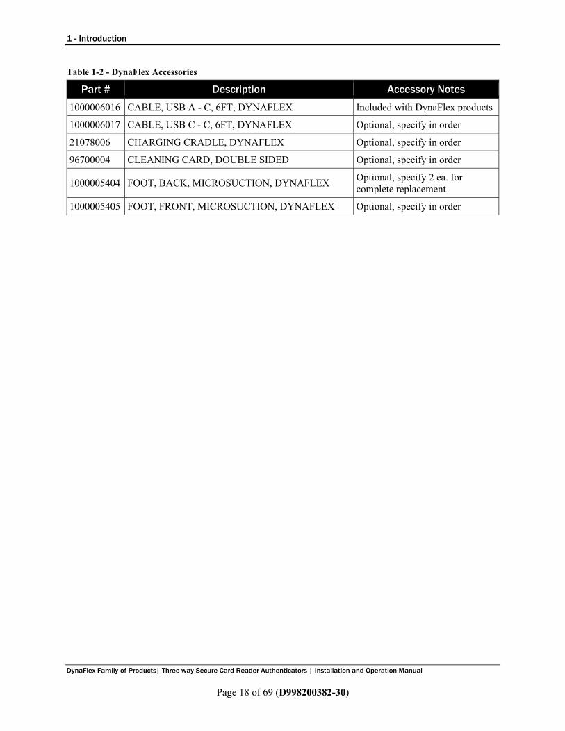
Table 1-2 - DynaFlex Accessories
Part # Description Accessory Notes
1000006016 CABLE, USB A - C, 6FT, DYNAFLEX Included with DynaFlex products
1000006017 CABLE, USB C - C, 6FT, DYNAFLEX Optional, specify in order
21078006 CHARGING CRADLE, DYNAFLEX Optional, specify in order
96700004 CLEANING CARD, DOUBLE SIDED Optional, specify in order
1000005404 FOOT, BACK, MICROSUCTION, DYNAFLEX Optional, specify 2 ea. for complete replacement
1000005405 FOOT, FRONT, MICROSUCTION, DYNAFLEX Optional, specify in order

1 - Introduction
DynaFlex Family of Products| Three-way Secure Card Reader Authenticators | Installation and Operation Manual
Page 19 of 69 (D998200382-30)
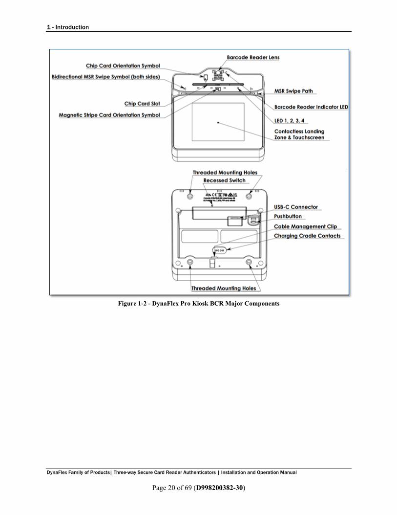
1.8 About DynaFlex Components Figure 1-1 shows the major components of DynaFlex Pro. The lanyard mount point is not visible in the figure. Figure 1-2 shows the major components of DynaFlex Pro Kiosk. Major components of models without touchscreen are identical to the diagrams, except the touchscreen and its bezel are replaced with a faceplate showing the contactless indicator logo placed at the optimal contactless landing zone. Major components of models without barcode reader are identical to the diagrams, except the edge that incorporates the barcode reader is a single straight line and there is no QR code marking on the face.
Figure 1-1 - DynaFlex Pro BCR Major Components
1 - Introduction
DynaFlex Family of Products| Three-way Secure Card Reader Authenticators | Installation and Operation Manual
Page 20 of 69 (D998200382-30)
Figure 1-2 - DynaFlex Pro Kiosk BCR Major Components

1 - Introduction
DynaFlex Family of Products| Three-way Secure Card Reader Authenticators | Installation and Operation Manual
Page 21 of 69 (D998200382-30)
Figure 1-3 shows the major components of the optional charging cradle. The drain holes provide drainage of liquid spills from the top surface of the cradle out through the bottom. The nesting feature allows mechanical joining of any number of charging cradles into a unified charging bank. Note, the charging cradle is only compatible with non-kiosk models of the device.
Figure 1-3 - Charging Cradle Major Components

2 - Planning and Preparation
DynaFlex Family of Products| Three-way Secure Card Reader Authenticators | Installation and Operation Manual
Page 22 of 69 (D998200382-30)
2 Planning and Preparation The guidelines in the following sections are intended to help project planners and system administrators plan for the physical and network requirements of deploying and using DynaFlex products. The most effective way to ensure smooth deployment of a solution is to consider these factors before receiving the device.
2.1 Logistical Planning • Determine what type of host DynaFlex products will connect to. For a list of supported host types
and operating systems, see Table 1-1 on page 17. When planning, be sure to include any additional support or devices required by the host and DynaFlex products, such as physical locations, mounting, power connections, and charging cradles.
• Determine what connection the host will use to communicate with the device. Depending on the device model (see Table 1-1 on page 17), the connection can be USB, Bluetooth LE, or a TCP/IP network that is equipped with wireless LAN or Ethernet. If the host will use the Bluetooth LE connection, make sure the host’s hardware and operating system support Bluetooth LE Secure Connections, which were introduced in the Bluetooth Core Specification version 4.2.
• Determine what software will be installed on the host and how it will be configured. Software can include operating system, transaction processing software, security software, and so on. If teams other than the software development team will be involved in preliminary device testing, MagTek recommends the solution development team provide a smoke test harness early in the development process to allow basic testing (for example, wireless range testing). In addition, be sure to plan for any additional support required by the software, such as software licenses and network connections. Information about software is provided in section 4.2 About Host Software.
• Configure the host software to select which combinations of magnetic stripe swipe, EMV contact card insertion, contactless payment tap, and/or manual entry the host will direct the device to accept (see section 6.9 Using the Readers). This decision may differ based on location, situation, and other factors, or may be uniform across all transactions and devices and hosts you are deploying.
• Determine how the device will be physically presented to the cardholder. If the device will be mounted, make sure there is adequate clearance for cardholders to swipe, insert, and tap. If the solution design includes metal objects anywhere near the device, including metal enclosures, make sure that at all points the metal is no further forward than 15mm below the face of the device. Proximity to metal can adversely affect the device’s performance.
• Determine how the device should be configured and specify that configuration when ordering the device. A full list of configurable options is documented in D998200383 DynaFlex Products Programmer’s Manual (COMMANDS). For example:
o For solutions that should accept AAMVA format cards, specify AMMVA format should be enabled. For ISO/ABA only solutions, specify it should be disabled.
o For solutions accepting ISO/ABA format cards, specify ISO track masking rules (masking character, number of leading and trailing unmasked characters, MOD-10 correction).
• Select and configure a secure workstation advanced operators will use to configure and/or update the device. The workstation must be configured as follows:
o Available USB port. o A secure means of obtaining files, either via the network (such as SFTP) or via removable
media, such as USB flash drives. This is required for installing software tools, copying firmware files, and so on. If you are using Magensa Services, make sure the secure workstation has an internet connection and has all required Magensa Remote Services software components installed.
2 - Planning and Preparation
DynaFlex Family of Products| Three-way Secure Card Reader Authenticators | Installation and Operation Manual
Page 23 of 69 (D998200382-30)
o 1000007406 DynaFlex, DynaProx Test Utility installed, which advanced operators can use to configure and test the device.
o 1000007405 DynaFlex, DynaProx Firmware Upload Utility installed, which advanced operators can use to update the device’s firmware.
• Determine the final set of tools advanced operators will use to configure, test, and update the device. This documentation uses the 1000007406 DynaFlex, DynaProx Test Utility as an example for configuring the device; it can be used for initial pre-deployment testing and development, and as sample code showing how to communicate with the device, but the full solution may call for customized, solution-specific software for configuring the device and updating firmware.
• Determine the charging schedule(s) and location(s). For example, high-traffic mission-critical solutions may benefit from keeping multiple devices charging for fast swap-out. Charging cradles and accessories are available directly from MagTek. Make sure there is an adequate number of USB wall chargers and / or USB ports available for the number of devices you are charging together, and make sure the electrical socket-outlet at a given charging location supports the total load. Solutions using large numbers of devices may benefit from using a large-scale universal USB charger / hub. Details about charging are provided in section 6.6 Power Management. Details about maximum power consumption are provided in Appendix A Technical Specifications.
• Determine how to inspect devices upon arrival, upon installation, and periodically during live usage to ensure malicious individuals have not tampered with them. Details about inspection are provided in section 4.1 About Inspection.
• Develop procedures for maintaining the device(s). Detailed guidance is provided in section 7 Maintenance.
• Determine how to train operators. For example, training may include information extracted from section 5 Configuration, section 6 Operation, and section 7 Maintenance.
• Review the device’s PCI Security Policy, posted to the PCI web site www.pcisecuritystandards.org under Approved PIN Transaction Security (PTS) Devices, for additional information about using the device securely.

3 - Handling and Storage
DynaFlex Family of Products| Three-way Secure Card Reader Authenticators | Installation and Operation Manual
Page 24 of 69 (D998200382-30)
2.2 Network Planning Reserved
3 Handling and Storage
Proper handling of the device throughout delivery, assembly, shipping, installation, usage, and maintenance is very important. Not following the guidelines in this document could damage the device, render it inoperable, and/or violate the conditions of the warranty.
3.1 Handling to Avoid Damage Upon receiving the device, inspect it to make sure it originated from an authentic source and has not been tampered with. For details, see D998200359 DynaFlex, (Contactless Pad, Pro, BCR) Device Inspection and D998200460 DynaFlex Kiosk, (Contactless Pad, Pro, BCR), Device Inspection, available from MagTek. From device delivery through assembly, shipping, installation, usage, and maintenance, the device must not be exposed to conditions outside the ratings in Appendix A Technical Specifications. If the device is exposed to cold temperatures, adjust it to warmer temperatures gradually to avoid condensation, which can interfere with the operation of the device or cause permanent damage. Do not drop or shake the device. For information about ongoing maintenance of the device, such as cleaning, see section 7 Maintenance.
3.2 Handling to Avoid Accidental Tamper DynaFlex products implement active tamper detection, which uses a small amount of electricity even when the device is completely powered off. The device primarily powers its active tamper detection circuitry using its rechargeable battery, if available. Devices with a rechargeable battery ship with the battery charged to between 45% and 65%, which provides a shelf life of up to 4 years. However, if the rechargeable battery completely discharges or the device does not contain a rechargeable battery, the device continues to power its active tamper detection circuitry using its non-rechargeable backup battery, which provides an additional 5 years of backup shelf life across the entire life of the device but does not recharge. If the rechargeable battery (if installed) and the backup battery are both allowed to completely discharge, the device’s tamper detection engages and locks down the device, and it must be returned to the manufacturer to reset. To avoid accidental tamper events and to optimally condition the battery, follow these precautions: • Temperature is the most critical factor in extending battery life and preserving battery charge. Store
the device at the lowest reasonable temperatures within its specified storage temperature range (see Appendix A Technical Specifications). Storing below 77°F / 25°C is optimal.
• If the device has a rechargeable battery and will be put directly into service, fully charge the device immediately upon receipt to extend its shelf life (see section 6.6.3 How to Charge the Battery).
• Before storing the device, charge the battery to less than 100% (60% is optimal).

4 - Installation
DynaFlex Family of Products| Three-way Secure Card Reader Authenticators | Installation and Operation Manual
Page 25 of 69 (D998200382-30)
• Before storing the device, power it off completely. See section 6.6.4 How to Power On / Wake Up from Standby Mode / Power Off.
• When stored, charge the device for one hour every 6 months to keep the battery chemistry in optimal condition and to ensure it does not completely discharge.
• Do not drop or shake the device.
4 Installation Installing DynaFlex products is straightforward: The manufacturer or acquirer configures the preferred settings, keys, terminal, and payment brand settings before deployment; end users need only set up a host with appropriate software, configure the software, and connect the device to the host. This section provides general information about inspecting, connecting, and installing DynaFlex products.
4.1 About Inspection Before unpacking the device, it is important to inspect its secure packaging to make sure it has not been tampered with in storage or in transit. MagTek provides details for inspecting the integrity of the device’s secure packaging in D998200361 DynaFlex Family (Contactless Pad, Pro, BCR, Kiosk, Kiosk Pro), Package Inspection. It is important to regularly and thoroughly inspect a new device before deployment and a device in live usage (including its immediate surroundings), to make sure malicious individuals have not tampered with it or its surroundings. MagTek recommends conducting inspection training for all device operators and an inspection schedule with checkpoints in place to make sure operators are performing inspections as specified and as scheduled. MagTek provides easy-to-follow device inspection references in D998200359 DynaFlex, (Contactless Pad, Pro, BCR), Device Inspection and D998200460 DynaFlex Kiosk, (Contactless Pad, Pro, BCR), Device Inspection.
4.2 About Host Software In any solution, DynaFlex products are connected to a host, which must have software installed that knows how to communicate with the device, and which is capable of processing transactions. To set up the host to work with DynaFlex products, follow the installation and configuration instructions provided by the vendor of the host or the host software. For information about developing custom host software, see section 8 Developing Custom Software.

4 - Installation
DynaFlex Family of Products| Three-way Secure Card Reader Authenticators | Installation and Operation Manual
Page 26 of 69 (D998200382-30)
4.3 Connecting to a Host
4.3.1 About Connecting to a Host The following sections provide steps for connecting DynaFlex products to a host via the various available physical connection types.
4.3.2 How to Connect DynaFlex Products to a Host or Charger via USB
Figure 4-1 - Connecting to a USB Host or USB Charger. Left: Countertop Models. Right: Kiosk Models
To connect DynaFlex products to a USB host or charger using the USB-C port, follow these steps (for reference see Figure 4-1 and section 1.8 About DynaFlex Components): 1) For best results, use the cable that is included with the device or another cable from Table 1-2 -
DynaFlex Accessories on page 18. These cables are designed specifically for DynaFlex products and include ferrite shielding at both ends of the cable to reduce emissions and interference. If the solution design requires an alternate cable, contact MagTek for assistance with ferrite selection and placement, and with connector overmold design.
2) Connect the USB-C end of the cable to DynaFlex or DynaFlex Pro. 3) If you plan to route the cable out the back of the device, route the cable through the cable
management clip to change its direction. Even if you are not routing out the back, you may use the cable clip for strain relief, to help stabilize the mechanical connection when cardholders or operators move the device or the cable.

4 - Installation
DynaFlex Family of Products| Three-way Secure Card Reader Authenticators | Installation and Operation Manual
Page 27 of 69 (D998200382-30)
4) Route the cable in the desired direction (e.g., out the back, left, right, down into the countertop, or into the mounting compartment of a kiosk).
5) Connect the other end of the USB cable to the charger or to the host’s USB port. 6) As soon as the device starts receiving power through USB, it automatically powers on. 7) If the specific device serial number you are connecting has not been connected to the host before, the
device shows Welcome on the display, and the Windows system tray on the host reports it is Setting up a device . When installation is complete (approximately 30 seconds later depending on the host), Windows reports Device is ready , and the device shows in Windows Device Manager under Human Interface Devices as two devices: HID-compliant vendor-defined device with VID 0801 and PID 2020 , and USB Input Device .
8) After successfully connecting to the host operating system via USB, the device shows Welcome or a
customized graphic on the display. 9) The operating system may put the device into USB Suspend mode. See section 6.6.8 About USB
Suspend.

4 - Installation
DynaFlex Family of Products| Three-way Secure Card Reader Authenticators | Installation and Operation Manual
Page 28 of 69 (D998200382-30)
4.3.3 How to Connect DynaFlex Products to a Host via Wireless LAN Reserved
4.3.4 How to Connect DynaFlex Products to a Host via the Bluetooth LE Connection Reserved

4 - Installation
DynaFlex Family of Products| Three-way Secure Card Reader Authenticators | Installation and Operation Manual
Page 29 of 69 (D998200382-30)
4.4 Mounting
4.4.1 About Mounting DynaFlex products are designed to provide flexible mounting options: • The integrated slip-resistant micro suction feet can simply be pressed onto any non-porous surface. • The integrated lanyard mount point can be used to hang or carry the device for convenient storage and
handling in grab-and-go solution designs. • Non-kiosk models of the device can be housed in the optional charging cradle and optionally
combined with the lanyard mount point, for quick grab-and-go and convenient drop-in charging between handheld sessions.
• DynaFlex products can be mounted to custom mounting brackets or mounted in an enclosure as part of a larger solution design.
4.4.2 How to Mount DynaFlex To mount DynaFlex products to a non-porous surface using the micro suction feet, simply press the device onto a clean, smooth, flat surface. Avoid rough, dirty, or uneven surfaces. To uninstall, simply twist the device to disengage the mounting feet. To use the optional charging cradle instead, see section 4.4.4 How to Mount the Charging Cradle. If your solution design involves custom mounting brackets, contact your MagTek representative to request design advice and assistance from MagTek’s Engineering team.

4 - Installation
DynaFlex Family of Products| Three-way Secure Card Reader Authenticators | Installation and Operation Manual
Page 30 of 69 (D998200382-30)
4.4.3 How to Mount DynaFlex Kiosk Models
This document describes how to use DynaFlex Kiosk models securely. Using the device in any way other than the approved methods described in this document invalidates the PCI PTS approval of the device. Not following the guidelines in this section could damage the device, render it inoperable, and/or violate the conditions of the warranty.
This section provides information and guidelines for designing the mechanical aspects of a solution that incorporates DynaFlex Kiosk models. MagTek strongly recommends vetting and testing solution designs before finalizing and deploying them to make sure the design meets all requirements (e.g., functional, legal, security, certification, safety, and so on). When designing the mechanical portions of a solution that incorporates DynaFlex Kiosk models, consider the following: • Review section 1.8 About DynaFlex Components for an overall introduction to the device’s
physical features and what they are called. • Review Appendix A Technical Specifications. • Review the information below about overall device dimensions and mounting hole locations and use. • Determine device orientation. The device supports all four orientations. • Review any additional requirements from other agencies, such as PCI and EMV solution certification
requirements, safety ordinances, and so on, which may introduce additional constraints to the design.

4 - Installation
DynaFlex Family of Products| Three-way Secure Card Reader Authenticators | Installation and Operation Manual
Page 31 of 69 (D998200382-30)
Overall dimensions of the device are shown in Figure 4-2. On request, MagTek can provide a 3D model of the device’s envelope to assist with the mechanical portion of solution design. MagTek strongly recommends building and testing prototypes with actual devices before finalizing the solution design.
Figure 4-2 - DynaFlex Kiosk Models Overall Dimensions
The screw hole placement on the bottom of DynaFlex Kiosk models is detailed in Figure 4-3. The holes are designed to accommodate screw size M4 x 0.7mm and a maximum screw depth of 0.315 inches (8mm). The recommended torque range for installing the screws is 20 to 22 in-lbs. (2.3 to 2.5 N-m).
Figure 4-3 - DynaFlex Kiosk Models Mounting Hole Locations

4 - Installation
DynaFlex Family of Products| Three-way Secure Card Reader Authenticators | Installation and Operation Manual
Page 32 of 69 (D998200382-30)
When designing the enclosure or mounting bracket, make sure there is adequate clearance for cardholders to swipe, insert, and tap. If the solution design includes metal objects anywhere near the device, including metal enclosures, ensure that at all points the metal is no further forward than 15mm below the top face of the device. Proximity to metal can adversely affect the device’s performance. As a security measure, the device must be installed such that cardholders have a full, unobstructed view of the housing around the card insertion slot opening (“entry zone”) and MSR swipe path prior to insertion or swipe. This is to allow cardholders to easily detect suspicious objects in or around the swipe path and card slot entry, such as bugs / skimmers / tapping mechanisms, and their wires or antennas. Be sure to select an installation height and mounting angle that meet this requirement.

4 - Installation
DynaFlex Family of Products| Three-way Secure Card Reader Authenticators | Installation and Operation Manual
Page 33 of 69 (D998200382-30)
4.4.4 How to Mount the Charging Cradle To mount the optional charging cradle to a countertop, follow these steps: 1) Determine how many charging cradles you will be installing. Any number of charging cradles can be
mechanically attached to form a single unified charging bank, using the tongue-and-groove joining features on their sides (see Figure 4-4).
2) Make sure you have a cable and corresponding USB receptacle for each charging cradle you are installing. For best results, use the cable that is included with the device; it includes shielding at both ends to reduce interference.
3) Determine where the charging cradle(s) should be placed. a) If you will use the charging cradle’s microsuction feet for mounting, make sure you are mounting
on a clean, smooth, flat surface. Avoid rough, dirty, or uneven surfaces. b) Factors to consider include cable length, cardholder and operator ergonomics, and access for
cleaning, maintenance, and repair. c) If the charging cradle will be used for charging in handheld operations, unobstructed removal is
also a consideration. 4) Connect each charging cradle to a USB port or to a USB charger with a minimum of 1A current
capability. For best results, use the cable that is included with the device. It includes shielding at both ends of the cable to reduce interference.
5) Join the charging cradles together into a charging bank, if desired. 6) Press the charging cradle’s microsuction feet onto the mounting surface. 7) To uninstall, twist the cradle to disengage the mounting feet. To separate two cradles, hold one cradle
down and pull gently up on the other.
Figure 4-4 - Joining Charging Cradles Into a Charging Bank

4 - Installation
DynaFlex Family of Products| Three-way Secure Card Reader Authenticators | Installation and Operation Manual
Page 34 of 69 (D998200382-30)
Figure 4-5 - Connecting the Charging Cradle and the Device

5 - Configuration
DynaFlex Family of Products| Three-way Secure Card Reader Authenticators | Installation and Operation Manual
Page 35 of 69 (D998200382-30)
5 Configuration The device does not have an on-screen configuration interface. However, it does have settings the host can change using commands. These settings are documented as Properties in D998200383 DYNAFLEX PRODUCTS PROGRAMMER'S MANUAL (COMMANDS). Additional commands and settings can be activated using Magensa Web Services. Contact [email protected] for further details.
5.1 How to Change the Active Connection Reserved.

6 - Operation
DynaFlex Family of Products| Three-way Secure Card Reader Authenticators | Installation and Operation Manual
Page 36 of 69 (D998200382-30)
6 Operation
6.1 About Operating Modes During operation, DynaFlex devices transition between distinct operating modes, which are important for operators to understand so they can properly control the device: • Powered Off Mode is the shipping and storage mode of the device. Operators would not generally
use this mode during a work shift or during off-shift recharging. It occurs when the operator holds the pushbutton for more than 8 seconds (or more than 12 seconds to force immediate power off without a proper shutdown sequence), or if the device’s battery is critically low and the device is not connected to a USB power source. In this mode, the device consumes practically no power. To move the device from Powered Off Mode to Active Mode, press the pushbutton for one second with the battery charged, or connect the device to USB power. If the device is already connected to USB power when it enters Powered Off Mode, it automatically powers back on.
• Reset Mode is a transient mode where the device first transitions to Powered Off Mode, then automatically powers back on. It occurs when the operator presses the recessed switch, or the host sends the Reset Device command, or the device automatically performs a daily security reset.
• USB Suspend Mode occurs when the USB host that is providing power to the device sends a USB Suspend control event to the device to conserve power. The device responds by powering off nearly all its modules including the display and listening for the USB host to send a USB Resume control event. To move the device from USB Suspend Mode to Active Mode, the host software must open a USB connection to communicate with the device, which signals the operating system that the device is in active use and should be allowed to draw full power from the USB port. It is not necessary for the host software to send commands to the device at that time.
• Active Mode is the device’s normal “awake” state when it is in use. In this mode, the touchscreen display and LEDs are powered on and the device is ready to receive commands from the host. This mode can be divided into substates like Active/Host Not Connected, Active/Host Connected, Active/Host Communicating, Active/Armed for Read, Active/Reading, and so on. These substates differ in the amount of power they consume and are mostly under the control of the host software. To move the device from Active Mode to Powered Off mode, press and hold the pushbutton for 8 seconds. If the device does not respond, continue holding the pushbutton for longer than 12 seconds to force immediate power off without a proper shutdown sequence. To move the device from Active Mode to Reset Mode, press the recessed switch.

6 - Operation
DynaFlex Family of Products| Three-way Secure Card Reader Authenticators | Installation and Operation Manual
Page 37 of 69 (D998200382-30)
6.2 Operation Overview During normal operation, the operator initiates a transaction from the host, and the cardholder interacts with the device. Devices with a touchscreen display provide on-screen prompts and interactive features such as buttons and signature capture. Transaction types may include sales, refunds, voids, authorization, new accounts, teller window applications, checking, savings, mortgages, retail transactions, or any other type of transaction where there is interaction between the cardholder and the operator. For each transaction type, the host software can direct the device to prompt the cardholder for any combination of magnetic stripe swipe, EMV contact card insertion, and/or contactless payment tap, and the transaction flow on the device may differ depending on what the host software specifies and what the cardholder does. Section 6.9 Using the Readers provides examples of the cardholder experience for each type of payment. Figure 6-1 shows a typical point of sale (POS) transaction sequence. If the device cannot read payment data, the host software may direct it to prompt the cardholder to repeat the action or request the cardholder revert to a different form of payment (such as using the magnetic stripe reader as a fallback instead of the chip card insertion slot).

6 - Operation
DynaFlex Family of Products| Three-way Secure Card Reader Authenticators | Installation and Operation Manual
Page 38 of 69 (D998200382-30)
Figure 6-1 - Typical Transaction Sequence

6 - Operation
DynaFlex Family of Products| Three-way Secure Card Reader Authenticators | Installation and Operation Manual
Page 39 of 69 (D998200382-30)
6.3 About the Status LEDs DynaFlex provides four RGB LEDs directly below the chip card insertion slot (see section 1.8 About DynaFlex Components), numbered LED1 through LED4, which report the device’s current operating status. • The meaning of each LED depends on the device’s operating mode. See section 6.1 About
Operating Modes and Table 6-1 below. Most of the time, operators will check the device’s status using the LEDs when it is in Active Mode while the device is not performing a transaction.
• LED colors have specific meanings, as described in Table 6-2. They are based on international conventions for traffic light colors, with additional colors reserved for unusual / special cases.
• LED blinking patterns have specific meanings as well, as described in Table 6-3. A blinking LED generally means the device is actively doing something to change the state that the LED is indicating and solid indicates a persistent state that would require an operator or cardholder to take action to change. One major exception is a device-wide functional failure state, such as a tamper state, where all LEDs flash urgently to call the attention of an advanced operator to intervene.
In this manual, specific combinations of LED colors and blinking patterns are described in more detail in the sections where they are relevant and use the same icons in the tables below to indicate color and blinking patterns. For example, information about how the LEDs show the device’s connection status is in section 4.3 Connecting to a Host.
Table 6-1 - DynaFlex LED Allocation
In This Context LED1 LED2 LED3 LED4
Active Mode, not armed for a tap transaction Power Connection Reserved Card Read Result
Active Mode, armed for a tap transaction Armed for Tap Tap Read Progress Tap Read Progress Card Read Result
Device-wide failure During major failures (such as tamper), LED1-LED4 report the nature of the failure based on the most likely steps required to resolve it.

6 - Operation
DynaFlex Family of Products| Three-way Secure Card Reader Authenticators | Installation and Operation Manual
Page 40 of 69 (D998200382-30)
Table 6-2 - DynaFlex LED Colors
Color Means
Red
Stop or stopped Example: LED1 is red. Stop using device: Battery is about to run out of charge.
Yellow
Wait or waiting Example: LED2 is yellow. Waiting for host to connect.
Green
Go, going, or went Example: LED2 is green. Host is connected, device is ready to Go.
Other Colors Reserved
Table 6-3 - DynaFlex LED Patterns
Color Means
Solid
Solid LEDs generally require an operator or cardholder to take action to change the state the LED is reporting. Example: Host is connected. Cardholder or host would have to disconnect. Example: Host is disconnected. Host would have to initiate connection.
Blinking
Blinking LEDs generally mean the device is in the process of doing / attempting something. Blink duty cycle and blink period are generally selected to show urgency or ongoing progress through a series of steps. Example: Device is attempting to connect to the WLAN access point.
Short time
LEDs sometimes light for a short time to indicate some process has ended (success or failure) and the device is going to transition to another state soon. Example: Successful card read.

6 - Operation
DynaFlex Family of Products| Three-way Secure Card Reader Authenticators | Installation and Operation Manual
Page 41 of 69 (D998200382-30)
6.4 About the Touchscreen Display The contents of this section only apply to DynaFlex Pro models, which have a display. When using a DynaFlex model that does not have a display, the device reports ongoing status to the host, which must present any necessary prompts and status information to the operator and / or the cardholder.
6.4.1 Welcome Page / Active Idle Page When the device is powered on, in Active mode, and idle (not performing a transaction or displaying host-driven user interface prompts), it shows Welcome or a custom graphic if it is configured to do so. If the host software is designed to receive and respond to cardholder input messages, pressing any area on the touchscreen when it is idle may trigger the host to perform an operation, such as starting a transaction. For more information about custom graphics, see D998200383 DynaFlex and DynaFlex Pro Programmer’s Manual (COMMANDS).
Figure 6-2 - Welcome Page Examples
The device may show text other than “Welcome” when it is Active / idle under certain conditions: • OFFLINE / Tampered means the device has detected an attempt to tamper with it (for example,
physical tampering, out-of-spec temperature range, electrical attack). If this occurs, remove the device from service and set it aside in a secure location for possible forensic analysis, and contact the manufacturer or your reseller for support. This mode can only be reset in the manufacturing facility.
• OFFLINE / Tamper not active means the device’s tamper detection system is not activated. The device is not configured properly. If this occurs, remove the device from service and contact the manufacturer or your reseller for support.
• OFFLINE / Security not activated means the device’s data security features have not been activated. The device is not configured properly. If this occurs, remove the device from service and contact the manufacturer or your reseller for support.
• OFFLINE / Security activated means the device is ready to have keys injected. If this occurs, remove the device from service and contact the manufacturer or your reseller for support.
• OFFLINE / HW missing means the device can not detect one or more of its installed modules. This may indicate a mechanical or electrical failure. If this occurs, remove the device from service and contact the manufacturer or your reseller for support.
• OFFLINE / Keys missing means the device is missing one of the encryption keys that are critical to its data security systems. The device needs to have keys properly injected. If this occurs, remove the device from service and contact the manufacturer or your reseller for support.
• OFFLINE without any clarifying text means the device is not ready for normal operation.

6 - Operation
DynaFlex Family of Products| Three-way Secure Card Reader Authenticators | Installation and Operation Manual
Page 42 of 69 (D998200382-30)
6.4.2 Device Information Page While powering up, the display briefly shows a page of information about the device, including the installed firmware part numbers and versions and other identifying information. To determine a device’s PCI certification status, compare the contents of this screen to the device’s listing on www.pcisecuritystandards.org, Approved PTS Devices. Note that in PCI listings, lowercase “x” is a wildcard meaning ‘any single character.’
Figure 6-3 - Device Information Screen
6.4.3 Connection Status Page Reserved

6 - Operation
DynaFlex Family of Products| Three-way Secure Card Reader Authenticators | Installation and Operation Manual
Page 43 of 69 (D998200382-30)
6.5 About Sounds DynaFlex products have a beeper that provides feedback to operators and cardholders about the internal state of the device: • The device sounds one short beep after it has successfully read a contactless tap, and the cardholder
can safely remove the card or device from the contactless landing zone. • The device emits short beeps continuously when a transaction is complete, but the card is still present
in the insertion slot. • The device emits two beeps when reading a card or contactless payment device to indicate a read
error occurred. • The device sounds two beeps when an operator cancels a pending EMV transaction. The device provides an internal setting the host can use to adjust the global system volume. The device does not provide an interface to change the volume setting directly via buttons or the touchscreen. If the device is too quiet or too loud: • Make sure the device is ordered from the manufacturer with the desired volume setting. • Check to see whether the host software you are using provides a feature to check and/or adjust the
volume setting. • If the host software does not provide that feature, request help from the development team that built
the host software to check / change the volume setting. For details, see D998200383 DYNAFLEX AND DYNAFLEX PRO PROGRAMMER'S MANUAL (COMMANDS).
6 - Operation
DynaFlex Family of Products| Three-way Secure Card Reader Authenticators | Installation and Operation Manual
Page 44 of 69 (D998200382-30)
6.6 Power Management
6.6.1 About Power This device incorporates a built-in Lithium-ion rechargeable battery, which requires very little maintenance. It is not subject to “charge memory” and therefore does not require deep discharge cycles to restore its charge capacity like many other battery technologies. When properly powered through its USB port, the device powers on automatically, remains powered on provided the host does not put it in USB Suspend mode, and draws power both for operation and for recharging the battery (see section 6.6.3 How to Charge the Battery). While charging, the device consumes more power from the USB connection than when the battery is fully charged. The device stops charging the battery when it determines it is optimally full, to prevent overcharging. If the device is not connected to USB power, or if the USB connection does not provide enough power, the device powers itself using the rechargeable battery. When the battery discharges to a critically low level, the device powers down automatically. It is critically important to not allow the device’s main battery to remain completely discharged any longer than absolutely necessary, or the device’s security features may lock it down and require a return to the manufacturer to reset. For information about how to prevent this from occurring during handling and storage, see section 3.2 Handling to Avoid Accidental Tamper. To prevent this from occurring during regular use: • Do not allow the device’s main battery remain completely discharged for prolonged periods of time,
and ideally do not allow it to ever reach 0%. Create a charging schedule that recharges the battery well before it is fully depleted.
• When the device is not connected to USB power, preserve the battery’s charge when it is not in use by putting the device into Sleep mode or powering it off completely (see section 6.6.4 How to Power On / Wake Up from Standby Mode / Power Off).
The device’s rechargeable battery is designed to last hundreds of charging cycles, but with time and / or with use, its charge capacity will naturally degrade. Following the recommendations in this section will maintain the battery’s charge capacity for as long as possible.
6.6.2 How to Check Battery Level Reserved.

6 - Operation
DynaFlex Family of Products| Three-way Secure Card Reader Authenticators | Installation and Operation Manual
Page 45 of 69 (D998200382-30)
6.6.3 How to Charge the Battery
Per UL requirements, the device is designed to not recharge its internal battery when the external temperature is below 0°C or above 40°C.
DynaFlex products have an onboard rechargeable battery to supply their own power when they are not powered through the USB-C port. The battery must be periodically recharged by connecting the device to the optional charging cradle, or to a USB port or stand-alone USB charger. Both the charging cradle and the device require a USB power supply that can provide at least 500mA @ 5V, optimally 1A @ 5V. To charge the device without an optional charging cradle, connect it to a USB charger or a USB host as described in section 4.3.2 How to Connect DynaFlex to a Host or Charger via USB. For best results, use the cable that is included with the device; it includes shielding at both ends to reduce interference. When charging, make sure the device is receiving enough power from the USB connection (battery level should increase even when device is in use). A full recharge cycle for a completely drained battery depends on how it is being charged. From a host USB port at 500mA, full charge takes approximately 7 hours. From a dedicated wall charger or charging cradle, a full charge make take as little as 4 hours. After connecting the device to a power source, make sure the LEDs indicate the device is charging (see section 6.3 About the Status LEDs). To charge the device in the optional charging cradle for power only (no USB communication): 1) Make sure the charging cradle is properly installed and is receiving USB power. See section 4.4.4
How to Mount the Charging Cradle. 2) Place the device in the charging cradle with the charging contacts pointing into the charging cradle
and the device’s face pointing toward the ceiling as shown in Figure 4-5 on page 34. 3) Check the device’s LEDs to make sure it is charging. For important information about the device’s power systems, optimal charging methods during regular use, optimal handling and storage, and other information about keeping the device’s power systems in the best possible condition, see section 3.2 Handling to Avoid Accidental Tamper and section 6.6.1 About Power.

6 - Operation
DynaFlex Family of Products| Three-way Secure Card Reader Authenticators | Installation and Operation Manual
Page 46 of 69 (D998200382-30)
6.6.4 How to Power On / Wake Up from Standby Mode / Power Off To power on the device, press and hold the pushbutton for one second, or connect the device to USB power. After powering on, devices with touchscreens show a page of information about the device, then transition to showing the Welcome page or custom graphics, if they are configured to do so. For more information about custom graphics, see D998200383 DynaFlex and DynaFlex Pro Programmer’s Manual (COMMANDS). To power off the device, disconnect the device from USB power. To reset the device, see section 6.6.5 How to Force Reset. If all LEDs are off, the device is in Powered Off mode, USB Suspend mode, or Standby mode. For details about reading the status of the device with LEDs, see section 6.1 About Operating Modes and section 6.3 About the Status LEDs.
6.6.5 How to Force Reset To force the device to reset, power it off then power it on again (see section 6.6.4 How to Power On / Wake Up from Standby Mode / Power Off). Alternatively, you may use a small tool such as a paperclip to carefully press the recessed switch inside the small hole on the bottom of the device (see section 1.8 About DynaFlex Components on page 19). The host may also reset the device by sending the Reset Device command (see section 8 Developing Custom Software). The device also automatically powers off if the rechargeable battery reaches a level that is low enough that the device may not be able to complete a transaction (see section 6.6.7 About Battery Warnings and Automatic Reset).
6.6.6 How to Turn Bluetooth LE Advertising On and Off Reserved.
6.6.7 About Battery Warnings and Automatic Reset Reserved
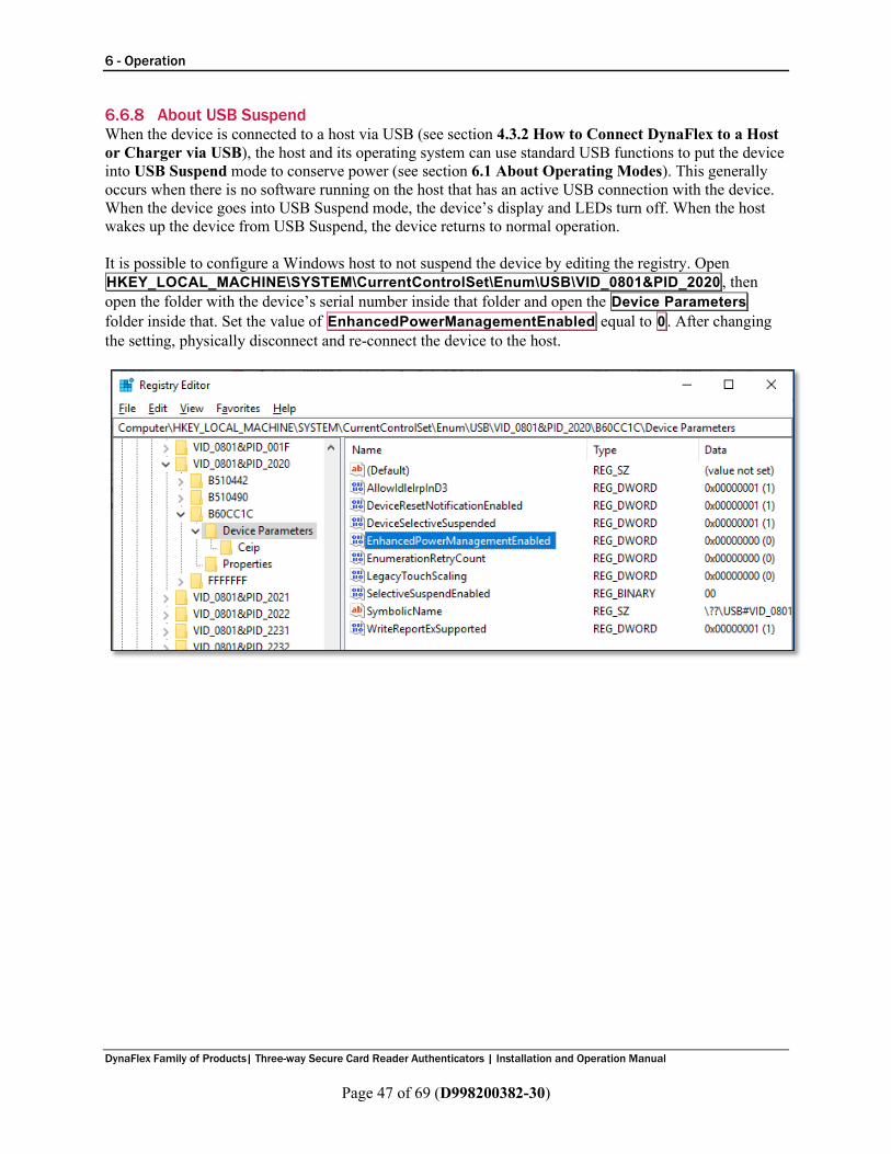
6 - Operation
DynaFlex Family of Products| Three-way Secure Card Reader Authenticators | Installation and Operation Manual
Page 47 of 69 (D998200382-30)
6.6.8 About USB Suspend When the device is connected to a host via USB (see section 4.3.2 How to Connect DynaFlex to a Host or Charger via USB), the host and its operating system can use standard USB functions to put the device into USB Suspend mode to conserve power (see section 6.1 About Operating Modes). This generally occurs when there is no software running on the host that has an active USB connection with the device. When the device goes into USB Suspend mode, the device’s display and LEDs turn off. When the host wakes up the device from USB Suspend, the device returns to normal operation. It is possible to configure a Windows host to not suspend the device by editing the registry. Open HKEY_LOCAL_MACHINE\SYSTEM\CurrentControlSet\Enum\USB\VID_0801&PID_2020 , then open the folder with the device’s serial number inside that folder and open the Device Parameters folder inside that. Set the value of EnhancedPowerManagementEnabled equal to 0 . After changing the setting, physically disconnect and re-connect the device to the host.
6 - Operation
DynaFlex Family of Products| Three-way Secure Card Reader Authenticators | Installation and Operation Manual
Page 48 of 69 (D998200382-30)
6.6.9 About Maintenance Reset For security purposes, the device is designed to perform an automatic maintenance reset periodically to clear all data from memory. When the device has been on continuously for 23 hours, it terminates all current operations, stops responding to new commands, and immediately performs a full reset. At the end of the automatic maintenance reset, the device powers back on and returns to normal operation.
6.7 How to Start a Handheld Transaction Using Wireless LAN Reserved
6.8 How to Start a Handheld Transaction Using the Bluetooth LE Connection Reserved

6 - Operation
DynaFlex Family of Products| Three-way Secure Card Reader Authenticators | Installation and Operation Manual
Page 49 of 69 (D998200382-30)
6.9 Using the Readers
6.9.1 About Reading Cards The steps for starting a transaction and reading a card or contactless payment device are different depending on the device’s configuration and on the design of the host software. Host software developers should see section 8 Developing Custom Software for implementation references. The solution developer should provide solution-specific instructions for operators to follow. A transaction generally follows this essential flow: 1) An advanced operator has already made sure DynaFlex or DynaFlex Pro is configured properly and is
connected to the host (see section 4.3 Connecting to a Host). When the device is connected to the host via USB and powered by the USB-C connector, the host software may always keep a connection open to the device.
2) The operator makes sure DynaFlex or DynaFlex Pro is receiving power either from its rechargeable battery or from the USB connection, and is awake and powered on (see section 6.6.4 How to Power On / Wake Up from Standby Mode / Power Off and section 6.3 About the Status LEDs).
3) The operator uses the host software’s user interface (for example, a point of sale) to finalize a transaction amount, then initiates a transaction. In solutions that are designed to respond to cardholder input events that occur when the device is idle, such as unprompted swiping, inserting, or tapping a card or electronic payment device, or pressing the touchscreen, the host software may respond to those inputs by notifying the host, and the host software may trigger other operations without being initiated by an operator (for example, the host software may immediately start a transaction, or alert the cardholder or operator to take action).
4) The host communicates with the device, and reports to the operator when the device is ready. 5) The operator guides and assists the cardholder in presenting payment. 6) The cardholder interacts with the device to present payment. The following sections provide
additional details about presenting each of the available payment methods. 7) Devices with a display show messages prompting the cardholder to perform certain actions. The host
should also monitor the progress of the transaction, and when necessary, should report issues to the operator, who may need to relay the messages to the cardholder.
8) The device reports the success or failure of the transaction to the cardholder and to the host.
6 - Operation
DynaFlex Family of Products| Three-way Secure Card Reader Authenticators | Installation and Operation Manual
Page 50 of 69 (D998200382-30)
6.9.2 How to Swipe Magnetic Stripe Cards To swipe magnetic stripe cards, follow these steps: 1) Wait for the device to display an action prompt, or, if the solution is designed to respond to
cardholder actions that occur while the device is idle, such as swiping, inserting, or tapping a card or electronic payment device, or pressing the touchscreen, initiate the transaction by performing one of those actions instead of waiting. In these cases, the device may automatically and rapidly pass through several of the steps below without requiring cardholder interaction. a) Devices with a display show on-screen text and buttons (see Figure 6-4 below for examples). b) The device shows the transaction status using the LEDs. If the host has directed the device to
enable the contactless interface, LED1 lights solid green and all other LEDs are off, per EMV standards, to indicate it is ready for a tap. If the host has directed the device to disable the contactless interface, the device continues to show idle statuses on LED1 and LED2.
c) All devices report detailed transaction status to the host, and host software may report that information to operators so they can guide cardholders through the transaction (for example, “swipe, insert, or tap your card now please”).
2) Locate the magnetic stripe reader swipe path on the face of the device. 3) Orient the card with the magnetic stripe facing away from the cardholder and the touchscreen or
contactless landing zone, toward the LEDs and the chip card insertion slot as shown in Figure 6-5. 4) Swipe the card through the magnetic stripe reader in either direction. 5) Look for a prompt that the device has successfully read the card:
a) The device turns LED4 green for a short time. b) The device beeps once. c) If the device has a display:
i) The device shows PROCESSING . ii) The device may show AUTHORIZING PLEASE WAIT . iii) If the transaction requires a signature, the device prompts for a signature (see section 6.9.8
How to Use Signature Capture). iv) The device shows THANK YOU .
d) The device ends the transaction and reports the transaction status to the host. 6) If the device can not read the card’s magnetic stripe data:
a) The device turns LED4 red for a brief time. b) The device beeps twice. c) The device ends the transaction. d) Devices with a display show FAILED , then THANK YOU , then return to the idle page (see
section 6.4.1Welcome Page / Active Idle Page). e) The device notifies the host that the transaction failed. If this occurs, the host software may
choose to retry the transaction or revert to prompting the operator to enter card data manually (see section 6.9.6 How to Enter Card Information Manually).
Immediately after the user swipes a magnetic stripe card, the device disables the option to use the contactless interface. If the cardholder needs to revert to a contactless card or device for payment while a transaction is in process, the operator should cancel the transaction and start again.

6 - Operation
DynaFlex Family of Products| Three-way Secure Card Reader Authenticators | Installation and Operation Manual
Page 51 of 69 (D998200382-30)
Figure 6-4 - Example Card Swipe Screens
Figure 6-5 - Swiping a Magnetic Stripe Card

6 - Operation
DynaFlex Family of Products| Three-way Secure Card Reader Authenticators | Installation and Operation Manual
Page 52 of 69 (D998200382-30)
6.9.3 How to Insert Contact Chip Cards To insert contact chip cards, follow these steps: 1) Wait for the device to display an action prompt, or, if the solution is designed to respond to
cardholder actions that occur while the device is idle, such as swiping, inserting, or tapping a card or electronic payment device, or pressing the touchscreen, initiate the transaction by performing one of those actions instead of waiting. In these cases, the device may automatically and rapidly pass through several of the steps below without requiring cardholder interaction. a) Devices with a touchscreen show on-screen text and buttons (see Figure 6-6 below for
examples). b) Devices with or without a touchscreen show the transaction status using the LEDs. If the host has
directed the device to enable the contactless interface, LED1 lights solid green and all other LEDs are off, per EMV standards, to indicate it is ready for a tap, swipe, or insert. If the host has directed the device to disable the contactless interface, the device continues to show idle statuses on LED1 and LED2.
c) All devices report detailed transaction status to the host, and host software may report that information to operators so they can guide cardholders through the transaction (for example, “swipe, insert, or tap your card now please”).
2) Locate the chip card insertion slot on the face of the device, as shown in Figure 6-7. 3) Orient the chip card so the chip faces the cardholder, toward the touchscreen or contactless landing
zone and the LEDs. 4) Insert the chip card into the slot, then push gently on the card until it stops. There should not be any
substantial resistance until the chip card is fully inserted. 5) Wait for a prompt that the device has successfully read the card, then remove the card.
a) The device turns LED4 green for a brief time. b) The device beeps once. c) If the device has a display:
i) The device shows PROCESSING . ii) The device shows PLEASE WAIT and/or AUTHORIZING PLEASE WAIT . iii) If the transaction requires a signature, the device prompts for a signature (see section 6.9.8
How to Use Signature Capture). iv) The device shows REMOVE CARD . v) The device shows THANK YOU .
d) The device ends the transaction and reports the transaction status to the host. e) As a reminder to the cardholder to remove the card, the device beeps continuously until the card
is removed. 6) If the device can not communicate with the chip card:
a) The device lights LED4 red for a short time. b) The device beeps twice. c) Devices with a display show FAILED , then REMOVE if the card is still in the slot, then THANK
YOU , then return to the idle page (see section 6.4.1Welcome Page / Active Idle Page). d) The device ends the transaction and notifies the host that the transaction failed. If this occurs, the
host software may choose to retry the transaction (for example, with different payment types enabled) or revert to prompting the operator to enter card data manually (see section 6.9.6 How to Enter Card Information Manually).
6 - Operation
DynaFlex Family of Products| Three-way Secure Card Reader Authenticators | Installation and Operation Manual
Page 53 of 69 (D998200382-30)
e) As a reminder to the cardholder to remove the card, the device double-beeps continuously until the card is removed.
Immediately after the user inserts a chip card, the device disables the option to use the contactless interface. If the cardholder needs to revert to a contactless card or device for payment while a transaction is in process, the operator should cancel the transaction and start again.
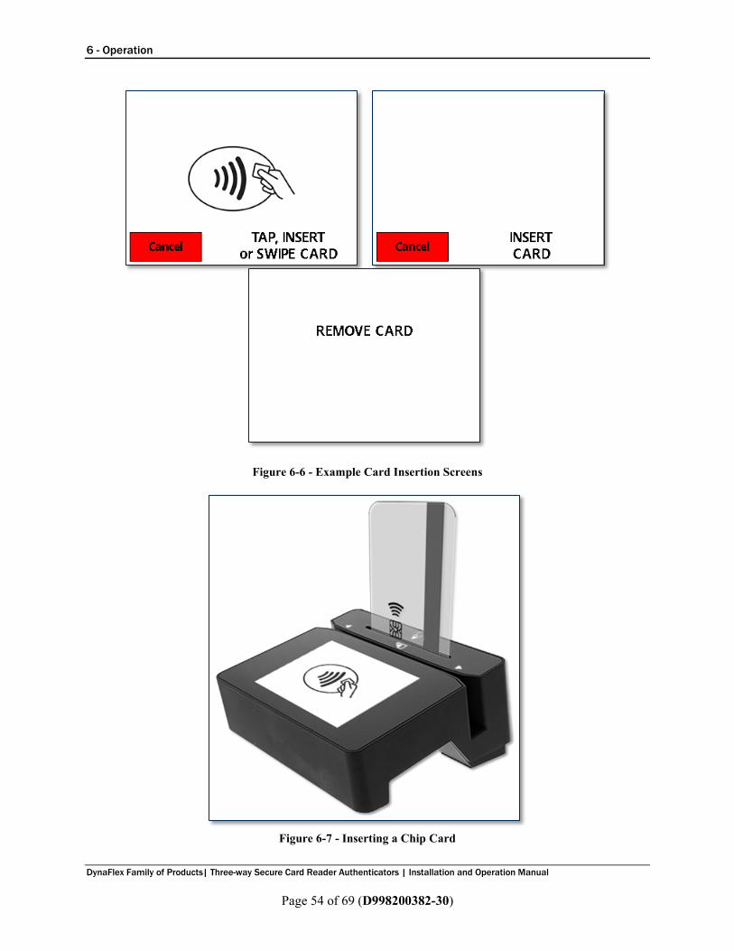
6 - Operation
DynaFlex Family of Products| Three-way Secure Card Reader Authenticators | Installation and Operation Manual
Page 54 of 69 (D998200382-30)
Figure 6-6 - Example Card Insertion Screens
Figure 6-7 - Inserting a Chip Card
6 - Operation
DynaFlex Family of Products| Three-way Secure Card Reader Authenticators | Installation and Operation Manual
Page 55 of 69 (D998200382-30)
6.9.4 How to Tap Contactless Cards / Devices To tap a contactless card or smartphone, follow these steps: 1) Wait for the device to display an action prompt, or, if the solution is designed to respond to
cardholder actions that occur while the device is idle, such as swiping, inserting, or tapping a card or electronic payment device, or pressing the touchscreen, initiate the transaction by performing one of those actions instead of waiting. In these cases, the device may automatically and rapidly pass through several of the steps below without requiring cardholder interaction. a) Devices with a touchscreen show on-screen text and buttons (see Figure 6-8 below for
examples). b) Devices with or without a touchscreen show the transaction status using the LEDs. LED1 lights
solid green and all other LEDs are off, per EMV standards, to indicate it is ready for a tap (or swipe or insert, if the host has enabled those interfaces for this transaction).
c) All devices report detailed transaction status to the host, and host software may report that information to operators so they can guide cardholders through the transaction (for example, “please tap your card now”).
2) If the cardholder is using an electronic payment device, such as a smartphone, make sure the payment device has NFC turned On and has a payment app configured to process transactions. For details, see the documentation provided by the smartphone manufacturer and payment app publisher.
3) Briefly hold the card, smartphone, or other contactless payment device over the contactless landing zone, indicated by the EMVCo Contactless Indicator symbol on the device’s face (see Figure 6-8). Because each smartphone model may have its NFC antenna placed differently, the ideal tap position may vary by make and model. For example, Samsung users may need to center the phone on the contactless landing zone, while Apple users may need to tap the top of the phone on the contactless landing zone.
4) Wait for a prompt that the device has successfully read the card, smartphone, or other contactless payment device, then remove it from the contactless landing zone. a) The device quickly lights the second LED green to show it is processing, then lights the third
LED green to show it has successfully read the tap, then lights the fourth LED green to show the read is complete (see Figure 6-10).
b) The device beeps once. c) If the device has a display:
i) The device may show PROCESSING . ii) The device shows REMOVE CARD . iii) If the transaction requires a signature, the device prompts for a signature (see section 6.9.8
How to Use Signature Capture). iv) The device shows THANK YOU .
f) The device ends the transaction and reports the transaction status to the host. 5) If the device can not communicate with the card, smartphone, or other contactless payment device:
a) The device ends the transaction. b) The device lights LED4 red for a brief time. c) The device beeps twice. d) Devices with a display show INSERT, SWIPE, OR TRY ANOTHER CARD , then THANK
YOU , then return to the idle page (see section 6.4.1 Welcome Page / Active Idle Page). e) The device notifies the host that the transaction failed. If this occurs, the host software may
choose to retry the transaction (for example, with different payment types enabled) or revert to

6 - Operation
DynaFlex Family of Products| Three-way Secure Card Reader Authenticators | Installation and Operation Manual
Page 56 of 69 (D998200382-30)
prompting the operator to enter card data manually (see section 6.9.6 How to Enter Card Information Manually).
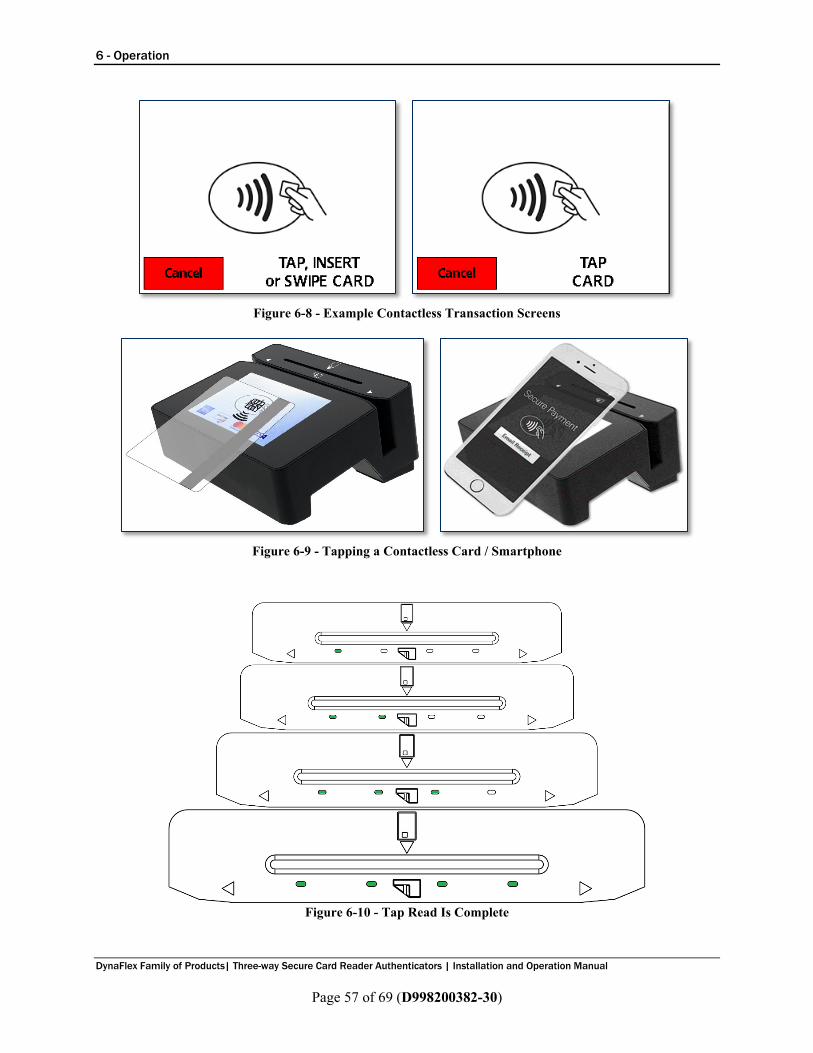
6 - Operation
DynaFlex Family of Products| Three-way Secure Card Reader Authenticators | Installation and Operation Manual
Page 57 of 69 (D998200382-30)
Figure 6-8 - Example Contactless Transaction Screens
Figure 6-9 - Tapping a Contactless Card / Smartphone
Figure 6-10 - Tap Read Is Complete

6 - Operation
DynaFlex Family of Products| Three-way Secure Card Reader Authenticators | Installation and Operation Manual
Page 58 of 69 (D998200382-30)
6.9.5 How to Scan Barcodes To scan a barcode, follow these steps: 1) Make sure you are using a DynaFlex model that includes a barcode reader, indicated by QR code
markings on the face of the device surrounding the barcode reader lens (see section 1.8 About DynaFlex Components).
2) If the barcode being scanned is not on a self-illuminated source such as a smartphone, make sure there is enough ambient light for the camera to read the barcode. In low light conditions, the barcode reader will only be able to read self-illuminated sources.
3) In some solutions, the operator may have to perform an operation in the host software to enable the barcode reader, or to start a transaction with the barcode reader enabled.
4) Wait for the device, the host, or the operator to prompt for a barcode read: a) Devices with a display show the prompt SCAN BARCODE . b) The device lights the barcode reader indicator LED next to the barcode reader lens.
5) Hold the barcode in front of the barcode reader camera: a) If possible, use the light from the barcode reader indicator LED to align the barcode within the
barcode reader’s field of view, which extends 16 degrees above / below and 21 degrees to the left / right of a line perpendicular to the barcode reader lens.
b) Hold the barcode as close as 1 inch from the lens. For smaller barcodes, the device will read immediately. If it does not, gradually pull back to up to 14 inches from the lens until the device reports a successful read. Larger barcodes must be far enough away from the device that the whole barcode is within the camera’s field of view; if a large barcode is too close, the barcode reader can only see a zoomed in portion of the barcode.
c) Do not tilt the barcode more than 60 degrees from parallel to the device’s face. 6) Wait for the device or the host to report the barcode has been read successfully:
a) Devices with a display will no longer show the prompt SCAN BARCODE . b) The device beeps once. c) The device turns off the barcode reader indicator LED.
Figure 6-11 – Scanning a Barcode

6 - Operation
DynaFlex Family of Products| Three-way Secure Card Reader Authenticators | Installation and Operation Manual
Page 59 of 69 (D998200382-30)
6.9.6 How to Enter Card Information Manually Devices with touchscreen displays provide support for starting a transaction that immediately prompts the operator or cardholder to enter card data manually. Manual entry can be useful in the following situations: • As a last-resort form of transaction fallback:
o The cardholder swiped during a transaction that had one or more card interfaces enabled, but the device could not read card data.
o The cardholder inserted a chip card during a transaction that had one or more card interfaces enabled, but the device could not read card data and could not fall back to swipe.
• In card not present transactions, including merchant locations where cardholders do not have their card, in telephone call centers, and so on. In these cases, the operator uses the device to keep sensitive data out of the merchant’s domain, for compliance / security reasons.
To enter card information manually, follow these steps. For every prompt below, press the Enter button after entering data to move to the next step, or press the Clear button to delete data that has already been entered but stay on the same step, or press the Cancel button to completely end the transaction: 1) The operator starts a transaction, specifying manual card entry, optionally specifying a transaction
amount and cash back amount. If the solution is designed to respond to cardholder actions that occur while the device is idle, such as pressing the touchscreen, the operator may initiate the transaction by performing one of those actions instead of initiating the transaction from the host.
2) The device shows a numeric keypad and a prompt to enter Card Number (see Figure 6-12). Enter the card number and press the Enter button. If the device double-beeps when pressing the Enter button and does not proceed to the next step, the PAN is not valid. The device may be configured to enable MOD10 validation, which makes sure the card number passes a validity check to prevent errors during entry. It is also possible you have entered too many or too few PAN digits. Double-check the card number and use the Clear button to correct any errors, then press Enter .
3) The device shows a numeric keypad and a prompt to enter Exp Date (MMYY) (see Figure 6-13). Enter the expiration date on the card and press the Enter button.
4) The device shows a numeric keypad and a prompt to enter CVV/CVC/Card ID . Enter the card verification code / value, then press the Enter button. This code is a 3- or 4- digit number printed on the front or back of the card, and is also referred to as a security code, security validation value, CAV2, CVC2, CVV2, or CID, depending on which payment brand issued the card.
5) The device shows a summary of all the data that was entered during the transaction. If the operator specified a transaction amount when starting the transaction, the summary includes the total transaction amount (purchase amount plus cash back, if any).
6) Verify all the information is correct: a) If it is correct, press the Enter button to proceed with the transaction. b) If it is correct but the cardholder or operator wishes to stop the transaction, press the Cancel
button to completely end the transaction. c) If it is not correct, press the Cancel button to completely end the transaction, and start the
transaction again from the first step.
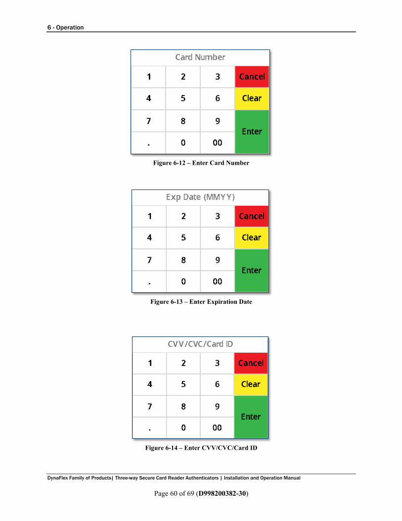
6 - Operation
DynaFlex Family of Products| Three-way Secure Card Reader Authenticators | Installation and Operation Manual
Page 60 of 69 (D998200382-30)
Figure 6-12 – Enter Card Number
Figure 6-13 – Enter Expiration Date
Figure 6-14 – Enter CVV/CVC/Card ID

6 - Operation
DynaFlex Family of Products| Three-way Secure Card Reader Authenticators | Installation and Operation Manual
Page 61 of 69 (D998200382-30)
6.9.7 How to Verify the Transaction Amount When the device is performing a transaction using the EMV Transaction Flow (as opposed to the Quick Chip Transaction Flow), devices with a display show the amount of the transaction when they prompt the cardholder to swipe, dip, or tap a card or payment device, as shown in Figure 6-15. The cardholder implicitly confirms / accepts the transaction amount by presenting payment.
Figure 6-15 - Example Transaction Amount Screens
6.9.8 How to Enter PINs Reserved Devices with a touchscreen display provide support for requesting PIN from the cardholder. The device prompts the cardholder to ENTER PIN (see Figure 6-15) as required by the financial institution. The device expects the PIN to be between 4 and 12 digits long. After entering the PIN, the cardholder must press the ENTER button.
Figure 6-16 – Enter PIN
If the double PIN entry option is enabled, the device prompts the cardholder to enter the PIN a second time (see Figure 6-16). The process for re-entry is identical to the process for the first entry.
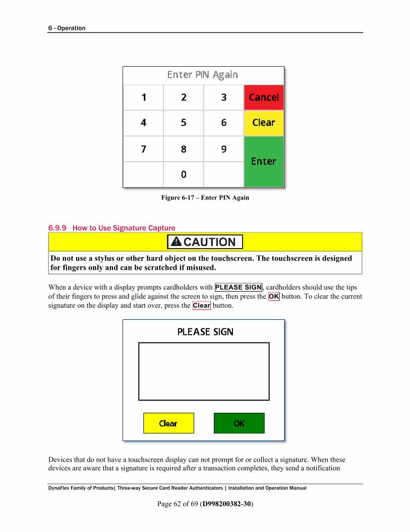
6 - Operation
DynaFlex Family of Products| Three-way Secure Card Reader Authenticators | Installation and Operation Manual
Page 62 of 69 (D998200382-30)
Figure 6-17 – Enter PIN Again
6.9.9 How to Use Signature Capture
Do not use a stylus or other hard object on the touchscreen. The touchscreen is designed for fingers only and can be scratched if misused.
When a device with a display prompts cardholders with PLEASE SIGN , cardholders should use the tips of their fingers to press and glide against the screen to sign, then press the OK button. To clear the current signature on the display and start over, press the Clear button.
Devices that do not have a touchscreen display can not prompt for or collect a signature. When these devices are aware that a signature is required after a transaction completes, they send a notification

6 - Operation
DynaFlex Family of Products| Three-way Secure Card Reader Authenticators | Installation and Operation Manual
Page 63 of 69 (D998200382-30)
message to the host that includes the status Signature Capture Requested. In this case, the solution design collects the cardholder’s signature via a different method.

7 - Maintenance
DynaFlex Family of Products| Three-way Secure Card Reader Authenticators | Installation and Operation Manual
Page 64 of 69 (D998200382-30)
7 Maintenance
7.1 Mechanical Maintenance
To avoid damaging the read head and contact block, only clean the MSR swipe path and insertion slot with approved cleaning cards. DO NOT use liquid cleaning products or insert any other objects into the device. DO NOT apply any liquid directly onto the device, to avoid seepage into the electronics.
Periodic cleaning of the device’s exterior may be required. To clean the outside of DynaFlex products, including the LCD display, wipe down the device with a soft, slightly damp cloth and then wipe dry with a lint-free cloth. The display can also be cleaned using a slightly damp specialty cleaning cloth, like those used to wipe lenses, monitors, and smartphone displays. MagTek’s double-sided cleaning card 96700004 is designed to clean the magnetic read head in the MSR swipe path and the contact pins inside all chip card contact readers. Keeping both components clean is essential to the device’s functioning. MagTek recommends swiping and inserting a cleaning card once per week to avoid card misreads. If the device’s micro-suction mounting feet lose their holding power over time, use a clean, damp, lint-free cloth to wipe the mounting feet and the mounting surface clean, then let both surfaces air dry. This should restore the mounting feet’s holding power. If the mounting feet are damaged and unusable, replacements are available. See section 1.7 Available Models and Accessories.
7.2 Updates to Firmware, Documentation, Security Guidance In addition to the security guidance in the product manuals, MagTek may provide updates to this document, as well as supplemental security guidance or notices regarding vulnerabilities, at www.magtek.com. MagTek advises checking the product’s home page periodically for the most up-to-date information. Any firmware updates addressing product features, bugs, or security vulnerabilities are also posted to www.magtek.com or may be sent directly to affected customers. To update the device’s firmware: 1) Obtain the firmware image to install. 2) Download 1000007405 DynaFlex, DynaProx Firmware Upload Utility from the MagTek web
site. 3) Follow the instructions in D100005288 DynaFlex, DynaProx Firmware Update Utility Manual
included in the firmware update utility’s Document subfolder.

8 - Developing Custom Software
DynaFlex Family of Products| Three-way Secure Card Reader Authenticators | Installation and Operation Manual
Page 65 of 69 (D998200382-30)
8 Developing Custom Software Custom host software uses the same underlying device command set for all DynaFlex product connection types. This section provides high-level information about communicating with the device via the various physical connection types in various software development frameworks, and provides pointers to available SDKs, which include sample code. Product documentation and SDKs are available for download by searching for the product name on www.magtek.com and navigating to the Support tab. MagTek provides convenient SDKs and corresponding documentation for many programming languages and operating systems. The API libraries included in the SDKs wrap the details of the connection in an interface that conceptually parallels the device’s internal operation, freeing software developers to focus on the business logic, without having to deal with the complexities of platform APIs for connecting to the various available connection types, communicating using the various available protocols, and parsing the various available data formats. Information about using MagTek wrapper APIs is available in separate documentation, including: • D998200380 Magtek Universal SDK Programmer’s Manual (Microsoft .NET) • D998200381 Magtek Universal SDK Programmer’s Manual (Microsoft C++ ) • D998200385 Magtek Universal SDK Programmer’s Manual (Java) • D998200387 Magtek Universal SDK Programmer’s Manual (Android) The documentation is bundled with the SDKs themselves, which include: • 1000007351 MagTek Universal SDK for MMS Devices (Windows) • 1000007352 MagTek Universal SDK for MMS Devices (Android) The SDKs and corresponding documentation include: • Functions for sending the direct commands described in this manual • Wrappers for commonly used commands that further simplify development • Sample source code to demonstrate how to communicate with the device using the direct commands
described in this manual To download the SDKs and documentation, search www.magtek.com for “SDK” and select the SDK and documentation for the programming languages and platforms you need or contact MagTek Support Services for assistance. In addition to the SDK API libraries, software developers also have the option to revert to direct communication with the device using libraries using the operating system’s native USB, TCP/IP, or Bluetooth LE libraries. For example, custom software written in Visual Basic or Visual C++ may make API calls to the standard Windows USB HID driver. For more information about sending commands directly, see D998200383 DynaFlex and DynaFlex Pro Programmer’s Manual (COMMANDS). For more information about developing custom applications that integrate with DynaFlex, see the MagTek web site or contact your reseller or MagTek Support Services.

Appendix A - Technical Specifications
DynaFlex Family of Products| Three-way Secure Card Reader Authenticators | Installation and Operation Manual
Page 66 of 69 (D998200382-30)
Appendix A Technical Specifications DynaFlex Products Technical Specifications
Reference Standards and Certifications
ISO 7810, ISO 7811, AAMVA ISO/IEC 7816-1, 2, 3, & 4 Identification Cards Integrated Circuits with Contacts EMV ICC Specifications for Payment Systems Version 4.3, L1 Contact and L2 Contact EMV Contactless Level 1 Version 3.0 MasterCard TQM MCL v3.1.3, payWave v2.2, Expresspay 4.0.2, D-PAS Terminal Payment Application v1.0, D-PAS Terminal Application Specification Bulletins CL TAS-002 v1.1, CL TAS-003 v1.0, CL TAS-004 v1.0 PCI PTS POI v5.1 SCR TDEA (3DES)-CBC using DUKPT FCC Part 15 Low Power Transceiver, RX verified per FCC Title 47 Part 15 Subclass C UL 60950 1, 2nd Edition, 2011 12 19 (Information Technology Equipment - Safety - Part 1: General Requirements), CSA C22.2 No. 60950 1 07, 2nd Edition, 2011 12 (Information Technology Equipment - Safety - Part 1: General Requirements) CE Certified UKCA Certified CE Safety: IEC 62368-1: 2014 UL/CSA 62368-1: 2nd Edition Canada ISED Certified Japan VCCI Certified (not applicable to WLAN models) Japan MIC Certified (not applicable to WLAN models) AS/NZS CISPR 32 (2013), AS/NZS 4268 Table 1, Row 59 DTS 2400-2483MHz SRD (WLAN), and AS/NZS 4268 (2017) Table 1, Row 43 13.553-13.567MHz (contactless reader) RoHS Compliant the Electrical and Electronic Equipment (EEE) Reduction of Hazardous Substances (RoHS) European Directive 2002/95/EC California Proposition 65 (California) IPC-A-610 Class II Assembly EU Directive Waste Electrical and Electronic Equipment (WEEE) EU Directive Restriction of Hazardous Substances (RoHS) Universal Serial Bus Specifications 1.1, 2.0 IEEE 802.11 b/g/n, IEEE 802.11i-2004 WPA2-PSK, TKIP, AES, SHA-256 TCP/IP secured by Transport Layer Security (TLS) Protocol v1.2 Bluetooth Core Specification 4.2
Physical Characteristics
Dimensions (L x W x H):
DynaFlex and DynaFlex Pro: 4.1 in. W x 3.7 in. L x 1.9 in. H (103.3mm x 95.1mm x 48.5mm) DynaFlex Kiosk and DynaFlex Pro Kiosk: 4.1 in. W x 3.7 in. L x 1.9 in. H (103.3mm x 95.1mm x 48.3mm)

Appendix A - Technical Specifications
DynaFlex Family of Products| Three-way Secure Card Reader Authenticators | Installation and Operation Manual
Page 67 of 69 (D998200382-30)
DynaFlex Products Technical Specifications
Weight
DynaFlex USB = 8.4 oz. (238g) DynaFlex Bluetooth LE= 8.7 oz. (247g) DynaFlex Pro USB= 8.7 oz. (246g) DynaFlex Pro Bluetooth LE / WLAN = 8.9 oz. (252g) Kiosk Models, add 1.1 oz. (30g) BCR Models, add 0.12 oz. (3.5g)
Supported Mounting Options: Microsuction feet Lanyard mount point
Reader Characteristics
Magnetic Stripe Reader: Three track bidirectional encrypting reader with MagnePrint
Magnetic Stripe Decoding: Financial (ISO Type B), AAMVA, or Other
Magnetic Swipe Speeds: 6 inches per second to 60 inches per second
EMV Contact Reader: EMVCo L1 and L2 Contact Reader
EMV Contactless Reader:
EMVCo L1 and L2 Contactless Reader D-PAS, PayPass/MCL, payWave, Expresspay Mobile wallets including but not limited to Apple Pay, Google Pay, Samsung Pay
Barcode Reader:
Barcode Media: Labels, paper, smartphone / computer displays Barcode Types: QR Codes, Linear Barcodes, UPC-A, UPC-E, Code 128, PDF417 / Data Matrix, etc. Field Of View 31.5° total vertical sweep, 42° total horizontal sweep, perpendicular to device face Depth Of Field 1.2 in. (30mm) to 13.8 in. (350mm) Integrated white indicator LED
User Interface Characteristics
Status Indicators: 4 RGB LEDs
Display Type: TFT a-Si Active Matrix Color LCD with Touchscreen (Select Models)
Display Size (viewable area): 2.3 in. x 1.7 in. (57.6mm x 43.2mm) (Select Models)
Display Resolution: 320 x 240 px, 16-bit color depth (Select Models)
Keypad: Touchscreen
Security Characteristics
Certifications: PCI PTS 5.1 POI Certified Secure Card Reader (SCR)
Tamper Protection: The enclosure and associated electronics form a Tamper Resistant Security Module (TRSM) where attempts to penetrate or modify the unit cause all cryptographic keys to be cleared or rendered unusable.

Appendix A - Technical Specifications
DynaFlex Family of Products| Three-way Secure Card Reader Authenticators | Installation and Operation Manual
Page 68 of 69 (D998200382-30)
DynaFlex Products Technical Specifications
Electrical Characteristics
Power Inputs: USB powered via USB-C receptacle or charging cradle connectors
Power Outputs: None
Battery Type: Lithium Polymer rechargeable
Battery Capacity: 2100 mAh nominal (rated)
Battery Charge Time: ~7 hours connected to a 500mA host USB port ~4 hours connected to a 1A wall charger or cradle
Battery Time, Powered Off 4 years or longer
Battery Time, Standby: Wireless LAN: Reserved Bluetooth LE: Reserved
Battery Time, Transactions: Reserved
Voltage Requirements: 5 VDC from USB port
Current Requirements: 500mA from USB port
Data Storage: Not Applicable
Communication Characteristics
Wired Connection Types: USB-C, compatible with USB 1.1, USB 2.0 Vendor-defined USB Human Interface Device (HID) data format
Wireless Connection Types: Bluetooth Low Energy (“Bluetooth LE”) (select models) TCP/IP over Wireless LAN (select models)
Wireless Range: WLAN: 100m in a typical environment Bluetooth LE: TBD
Wireless Frequencies and Power:
Wireless LAN Frequency range = 2400 MHz to 2484 MHz Average power radiated = 0.80 mW (-0.97 dBm) Bluetooth LE Frequency range = 2400 MHz to 2480 MHz Average power radiated = 0.07 mW (-11.55 dBm) NFC: Frequency range = 13.56 MHz Maximum power conducted = 794 mW (29 dBm)
RF Exposure: Exempt from SAR requirements due to radiated power substantially below regulatory thresholds.
Software Characteristics
Tested Operating System(s): USB Hosts: Windows 10, Android 6 and above

Appendix A - Technical Specifications
DynaFlex Family of Products| Three-way Secure Card Reader Authenticators | Installation and Operation Manual
Page 69 of 69 (D998200382-30)
DynaFlex Products Technical Specifications
Environmental Resistance
Ingress Protection: Splash Resistant
Operating Temperature: 32°F to 113°F (0°C to 45°C)
Operating Relative Humidity: 5% to 90% non-condensing
Storage Temperature: 14°F to 140°F (-10°C to 60°C)
Storage Relative Humidity: 5% to 90% non-condensing
Vibration Resistance: 5Hz to 500Hz sinusoidal vibrations at 15g acceleration, all 3 axes
Shock Resistance: 30g 11ms terminal sawtooth shocks, all 3 axes
ESD Tolerance (EMVCo): ±10kV air discharge when device is properly earth grounded
ESD Tolerance (FCC/CE): ±8kV contact discharge / ±12kV air discharge when properly grounded
Vapor Resistance: Not Applicable
Reliability
Shelf Life: 24 months at 25°C nominal
Magnetic Read Head Life: 1 million swipes
ICC Read Head Life: 500,000 card insertions
Battery Shelf Life: 2 years or longer (backup battery)
Battery Cycle Life: After 500 charge / discharge cycles, battery capacity remains above 80%.


![EID Reader Manual Installation Card Reader... · EID Reader Manual Installation [FAQ, Perquisite & Guides] Document Details EID Reader Manual Installation and Troubleshooting Software](https://static.fdocuments.us/doc/165x107/5e2b1bd34debb043f0778de5/eid-reader-manual-installation-card-reader-eid-reader-manual-installation-faq.jpg)


![Secure Programming for Linux HOWTO...documents including Fenzi [1999], Seifried [1999], and Wreski [1998]. This paper assumes that the reader understands computer security issues in](https://static.fdocuments.us/doc/165x107/5e5cea6fa3dab1666546dcae/secure-programming-for-linux-documents-including-fenzi-1999-seifried-1999.jpg)