
Three Phase Inverter Motors Ben Kemink. FORESIGHT INNOVATION QUALITY 2 At the end of this training...
22
Three Phase Inverter Motors Ben Kemink
-
Upload
elvin-goodwin -
Category
Documents
-
view
216 -
download
0
Transcript of Three Phase Inverter Motors Ben Kemink. FORESIGHT INNOVATION QUALITY 2 At the end of this training...

Three Phase Inverter Motors
Ben Kemink

2FORESIGHT
INNOVATIONQUALITY
At the end of this training session you will have learned;
1. There are different three-phase measurements.
2. Pulse Width Modulation.3. Inverter Driven Applications mess-up with
Period Time T.
Three Phase Inverter Motor

3FORESIGHT
INNOVATIONQUALITY
Three Phase Systems
A One-Phase System, also called a Single-Phase (SP) System works very much similar to a DC network and can be considered so far at any particular moment in time.
Electrical Systems comprising two or more phases are also called Multi-Phase or Poly-Phase (PP) systems.
The voltage amplitudes and frequencies in the individual system circuits are the same, but they have definite phase differences.

4FORESIGHT
INNOVATIONQUALITY
Why Poly-Phase?
The technical complications and economical investments are small compared to the enormous advantages of a Poly-Phase system:
1. Same size generator or motor, higher output.
2. Same energy transmission less copper required.
3. PP motors have uniform torque, SP have pulsating torque *).
4. PP motors are self-starting, SP are not *).
5. Polyphase generators work fine parallel, SP not.
*) Single Phase commutator motors are exception.

5FORESIGHT
INNOVATIONQUALITY
Why 3 Phase and not 7?

6FORESIGHT
INNOVATIONQUALITY
Three Phase is ideal
Source: Advanced Electrical Technology by H.Cotton

7FORESIGHT
INNOVATIONQUALITY
Three-Phase Three-Wire
Total Power calculation based on Two-Watt-meter method
3 wires – 1 = 2 power meters required

8FORESIGHT
INNOVATIONQUALITY
Three-Phase Four-Wire
4 wires - 1 = 3 Watt meters are required
9FORESIGHT
INNOVATIONQUALITY
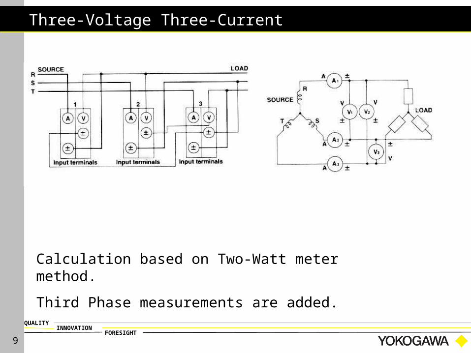
Three-Voltage Three-Current
Calculation based on Two-Watt meter method.
Third Phase measurements are added.

10FORESIGHT
INNOVATIONQUALITY
Three-Phase Three-Wire with PT & CT

11FORESIGHT
INNOVATIONQUALITY
Introduction
What is Three phase?
Three phase = three signals Phase shift: 1200
Figure 1: Phase shift 1200

12FORESIGHT
INNOVATIONQUALITY
Pulse Width Modulation of a Sine Wave

13FORESIGHT
INNOVATIONQUALITY
Demonstration circuit
Demonstration circuit consists of:
Frequency inverter; 3-Phase Electromotor; Power meter;
Figure 2: Demonstration circuit

14FORESIGHT
INNOVATIONQUALITY
Demonstration circuit
Freq. inverter
Step 1: AC → DC Step 2: DC → 3-Phase
Control unit
T
L1(mains)
50 Hz
T
0 Hz →
Figure 3: Block diagram 1phase inverter

15FORESIGHT
INNOVATIONQUALITY
Demonstration circuit
AC → DC Performed by rectifier; DC-signal is
smoothened by capacitor;
In 3phase mains the output of the rectifiers is connected to the same capacitor;
t →
Example: Single phase rectifying
Freq. inverter Step 1: rectifying
Figure 4: rectifier

16FORESIGHT
INNOVATIONQUALITY
Demonstration circuit
Freq. inverter Step 2: regeneration of 3-Phase-signals
Six switches Generate periodic pulse-trains; Insulated Gate Bipolair Transistor (IGBT); High frequency switches;
U
tt
Figure 5: Inverter step 2: regeneration of AC-signals
New Period T

17FORESIGHT
INNOVATIONQUALITY
Demonstration circuit
Freq. inverter
YEF-HQ Test Motor
Figure 6: Output of Freq. Inverter: 1-phase, current (green) / voltage (yellow)

18FORESIGHT
INNOVATIONQUALITY
Running the motor
Direction Direction (CCW or CW)
Can be changed by manipulating the pulses
CW
CCW
U
V
W
U
V
W
19FORESIGHT
INNOVATIONQUALITY
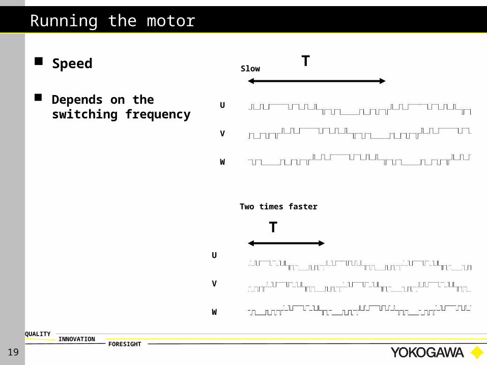
Running the motor
Speed
Depends on the switching frequency
Slow
Two times faster
U
V
W
U
V
W
T
T

20FORESIGHT
INNOVATIONQUALITY
Running the motor
Faster 1s time window
Speed:voltage (yellow) and current (green)
Slow 1s time window
Figure 7: Output of Freq. Inverter at different speeds

21FORESIGHT
INNOVATIONQUALITY
Now you have learned;
1. There are different three-phase measurements.
2. What Pulse Width Modulation is.3. Why Inverters mess-up with Period Time T.
22FORESIGHT
INNOVATIONQUALITY
Thank you for your attention