
three phase and earth fault overcurrent relays -...
8
Protection Relays The MiCOM P12x/y relays provides features for easy adaptation and are suitable for all applications where overcurrent and earth-fault protection are required. The MiCOM P12x non-directional relays ranges from the single phase/earth fault P120 up to the multifunction three phase and earth fault P123. The MiCOM P12y directional relays ranges from the single phase/earth fault P125 up to the multifunction three phase and earth fault P127, complete of voltage and frequency protection functions. Users particularly appreciate the friendliness of the Human Machine Interface and the easy setting of the relays (that can be fully set through the front HMI or using MiCOM S1 setting software). In addition to its protection function, MiCOM P12x/y provides full measurement and monitoring information necessary for efficient maintenance and post-fault analysis. Several communication protocols allow easy interfacing of the MiCOM P12x/y relays in most of substation control or SCADA systems. The MiCOM P12x/y range is housed in the same draw out 4U metal case for panel or rack mounting with 20TE width (P120, P121, P122, P123 and P125) or 30TE width (P126 and P127). APPLICATION MiCOM P12x/y provides a wide range of protection functions allowing its use in several applications: • Main or backup protection on MV&HV systems • Overhead lines and underground cables as a backup on HV systems • Neutral systems protection (Insolated, solid earthed, resistance earthed and Petersen coil earthed) • MV subscribers, Industry, Transport • Generator and transformer scheme • High impedance scheme for busbar and machine protection OVERVIEW The following functions are available in most of the devices (see Protection Function Overview tables): • Measurement and metering • Dynamic average values, max peak value and rolling demand for the current measurements • Disturbance recording including all the CT/VT inputs and logic status • Fault recording • Event recording 01 MiCOM P12x/y Three phase and earth fault overcurrent relays CUSTOMER BENEFITS • Integration of function leading to cost- effective solution • User friendly Human Machine Interface • Highly flexible overcurrent relay with logic equations • Multi-shot Autoreclose • One single configuration software MiCOM S1 Studio • Full set of measurement, metering & recording
Transcript of three phase and earth fault overcurrent relays -...

Protection Relays
The MiCOM P12x/y relays provides features for easy adaptation and are suitable for all applications where overcurrent and earth-fault protection are required.
The MiCOM P12x non-directional relays ranges from the single phase/earth fault P120 up to the multifunction three phase and earth fault P123.
The MiCOM P12y directional relays ranges from the single phase/earth fault P125 up to the multifunction three phase and earth fault P127, complete of voltage and frequency protection functions.
Users particularly appreciate the friendliness of the Human Machine Interface and the easy setting of the relays (that can be fully set through the front HMI or using MiCOM S1 setting software).
In addition to its protection function, MiCOM P12x/y provides full measurement and monitoring information necessary for efficient maintenance and post-fault analysis.
Several communication protocols allow easy interfacing of the MiCOM P12x/y relays in most of substation control or SCADA systems.
The MiCOM P12x/y range is housed in the same draw out 4U metal case for panel or rack mounting with 20TE width (P120, P121, P122, P123 and P125) or 30TE width (P126 and P127).
APPlicAtionMiCOM P12x/y provides a wide range of protection functions allowing its use in several applications:
• Main or backup protection on MV&HV systems• Overhead lines and underground cables as a backup on HV systems• Neutral systems protection (Insolated, solid earthed, resistance earthed
and Petersen coil earthed)• MV subscribers, Industry, Transport• Generator and transformer scheme• High impedance scheme for busbar and machine protection
oVERViEWThe following functions are available in most of the devices (see Protection Function Overview tables):
• Measurement and metering• Dynamic average values, max peak value and rolling demand for the
current measurements• Disturbance recording including all the CT/VT inputs and logic status• Fault recording • Event recording
01
MicoM P12x/ythree phase and earth fault overcurrent relays
custoMER bEnEfits
• Integration of function leading to cost-effective solution
• User friendly Human Machine Interface
• Highly flexible overcurrent relay with logic equations
• Multi-shot Autoreclose
• One single configuration software MiCOM S1 Studio
• Full set of measurement, metering & recording
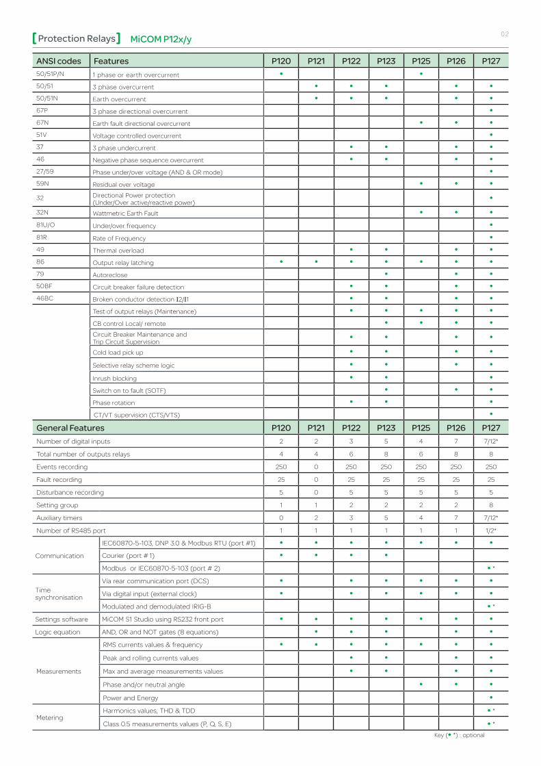
MicoM P12x/yProtection Relays 02
Ansi codes features P120 P121 P122 P123 P125 P126 P12750/51P/N 1 phase or earth overcurrent • •
50/51 3 phase overcurrent • • • • •
50/51N Earth overcurrent • • • • •
67P 3 phase directional overcurrent •
67N Earth fault directional overcurrent • • •
51V Voltage controlled overcurrent •
37 3 phase undercurrent • • • •
46 Negative phase sequence overcurrent • • • •
27/59 Phase under/over voltage (AND & OR mode) •
59N Residual over voltage • • •
32 Directional Power protection (Under/Over active/reactive power)
•
32N Wattmetric Earth Fault • • •
81U/O Under/over frequency •
81R Rate of Frequency •
49 Thermal overload • • • •
86 Output relay latching • • • • • • •
79 Autoreclose • • •
50BF Circuit breaker failure detection • • • •
46BC Broken conductor detection I2/I1 • • • •
Test of output relays (Maintenance) • • • • •
CB control Local/ remote • • • •
Circuit Breaker Maintenance and Trip Circuit Supervision
• • • •
Cold load pick up • • • •
Selective relay scheme logic • • • •
Inrush blocking • • •
Switch on to fault (SOTF) • • •
Phase rotation • • •
CT/VT supervision (CTS/VTS) •
General features P120 P121 P122 P123 P125 P126 P127 Number of digital inputs 2 2 3 5 4 7 7/12*
Total number of outputs relays 4 4 6 8 6 8 8
Events recording 250 0 250 250 250 250 250
Fault recording 25 0 25 25 25 25 25
Disturbance recording 5 0 5 5 5 5 5
Setting group 1 1 2 2 2 2 8
Auxiliary timers 0 2 3 5 4 7 7/12*
Number of RS485 port 1 1 1 1 1 1 1/2*
Communication
IEC60870-5-103, DNP 3.0 & Modbus RTU (port #1) • • • • • • •
Courier (port # 1) • • • •
Modbus or IEC60870-5-103 (port # 2) • *
Time synchronisation
Via rear communication port (DCS) • • • • • •
Via digital input (external clock) • • • • • •
Modulated and demodulated IRIG-B • *
Settings software MiCOM S1 Studio using RS232 front port • • • • • • •
Logic equation AND, OR and NOT gates (8 equations) • • • • •
Measurements
RMS currents values & frequency • • • • • • •
Peak and rolling currents values • • • •
Max and average measurements values • • • •
Phase and/or neutral angle • • •
Power and Energy •
MeteringHarmonics values, THD & TDD • *
Class 0.5 measurements values (P, Q, S, E) • *
Key (• *) : optional
MicoM P12x/yProtection Relays 03
METERING
RECORDINGFEATURES
CTs N N 46N
86
N
N
VTS
MEASUREMENTS
MiCOM P127 Directional Overcurrent Relay
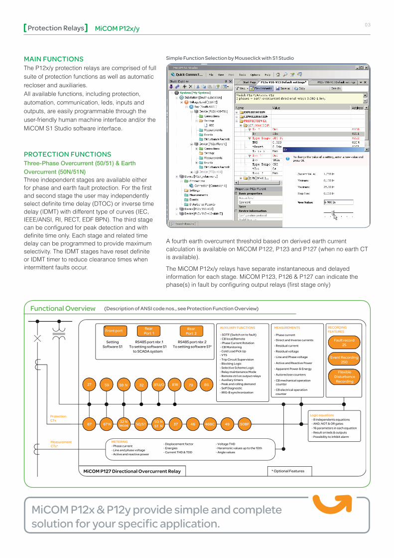
functional overview (Description of Ansi code nos., see Protection function overview)
MicoM P12x & P12y provide simple and complete solution for your specific application.
MAin functionsThe P12x/y protection relays are comprised of full suite of protection functions as well as automatic recloser and auxiliaries.All available functions, including protection, automation, communication, leds, inputs and outputs, are easily programmable through the user-friendly human machine interface and/or the MiCOM S1 Studio software interface.
PRotEction functions Three-Phase Overcurrent (50/51) & Earth Overcurrent (50N/51N)Three independent stages are available either for phase and earth fault protection. For the first and second stage the user may independently select definite time delay (DTOC) or inverse time delay (IDMT) with different type of curves (IEC, IEEE/ANSI, RI, RECT, EDF BPN). The third stage can be configured for peak detection and with definite time only. Each stage and related time delay can be programmed to provide maximum selectivity. The IDMT stages have reset definite or IDMT timer to reduce clearance times when intermittent faults occur.
simple function selection by Mouseclick with s1 studio
A fourth earth overcurrent threshold based on derived earth current calculation is available on MiCOM P122, P123 and P127 (when no earth CT is available).
The MiCOM P12x/y relays have separate instantaneous and delayed information for each stage. MiCOM P123, P126 & P127 can indicate the phase(s) in fault by configuring output relays (first stage only)

MicoM P12x/yProtection Relays 04
Three-Phase & Earth-Fault Directional Overcurrent (67/67N)Each of the three-phase overcurrent stages of P127 & earth fault stages of P125/6/7 can be independently configured as directional protection and with specific characteristic angle (RCA) and boundaries. The phase fault directional elements are internally polarised by quadrature phase to phase voltages. A synchronous polarising function is provided to ensure a correct operation of the overcurrent elements for close-up three phase faults where the collapse of the polarising line voltages occurs. In addition to the residual current, the residual voltage must be connected to a dedicated input or internally calculated as vector sum (P127 only) in order to make possible the directional operation of the earth-fault. Each earth-fault directional stage measures the residual current, the residual voltage, and the angle between residual voltage and current.
Thermal Overload (49)Transformers and cables must be protected taking into account of their particular thermal characteristics. MiCOM P122/3 & P126/7 relays include a thermal replica element based on the true RMS value of the current, up to 10th harmonic. Alarm and overload thresholds and time constant are fully programmable to match each application requirement.
High Impedance Restricted Earth-Fault (64N)MiCOM P12x range offer the REF feature applied to enhanced ground fault detection on each transformer winding.
The relays ensure a high degree of stability against external fault conditions and a reliable performance against internal faults.
All the 50N/51N stages can be used for this application.
Negative Sequence Overcurrent (46)The MiCOM P122/3 & P126/7 relays include a programmable function specially designed to detect unbalanced load or fault conditions.
The three stages of negative sequence overcurrent have the same setting ranges and time delay as the phase overcurrent.
Broken Conductor (46BC)A typical unbalanced fault that can occur on the system is an open circuit fault. This fault can arise from broken conductor, discrepancy of one switchgear poles position or blowing of a fuse.
MiCOM P122/3 and P126/7 relays are able to measure the ratio of negative to positive sequence current (I2/I1). This fully programmable function allows more sensitivity and stability than pure negative sequence measurement.
Directional Power Protection (32)MiCOM P127 relays provides a full set of directional power protection including two independants threshold for each of the following function :• 3-phases under active power (P<, P<<)• 3-phases over active power (P>, P>>)• 3-phases under reactive power (Q<, Q<<)• 3-phases over reactive power (Q>, Q>>)
Undercurrent Protection (37)MiCOM P122/3 & P126/7 relays provide a definite time undercurrent protection. This function allows typical applications such as loss of load or simple broken conductor detection.
High Impedance Three-Phase Differential Protection (87)The phase inputs of MiCOM P12x relays can be applied in the typical high-impedance scheme for busbar or machine protection.
The relays ensure a high degree of stability against external fault conditions and a reliable performance against internal faults.
All the 50/51 stages can be used for this application, the third stage configured in peak mode is recommended for the best performance.
>
I<
Current
Time
t>>I>>
t>I
I th
I>>> t>>>
tripping characteristics
UI
Reverse tripping zone
RCAangle
Forward
tripping
zone
Directional overcurrent tripping Zone
cost effective solution for small generators and network interconnection protection

MicoM P12x/yProtection Relays 05
P
Q
Triggering power
Active power (P)
2°
2°
P< and
and
P<<
P>P>> Trip zone
Trip zone
DirectionalAngle
0
90
180
270
Directional Active over / under Protection
Under / Over Voltage (27/59)The P127 relay provides two independent under-voltage stages and two over-voltage stages. They are definite time elements. Each stage can be configured to operate from either phase-neutral or phase-phase voltages in single-phase mode (OR mode) or three-phase mode (AND mode).
Under / Over Frequency (81U/O)Time delayed under and over frequency protection available on P127 provides the fundamental form of frequency protection. When the frequency measured is crossing one of the 6 pre-defined thresholds, the relays generates a start signal and after a user settable time delay, a trip signal.
Rate of Frequency (81R)Time delayed rate of frequency protection in MiCOM P127 is used for severe disturbances when shedding load in small steps may not be sufficient. It can also compliment the generator control system to reduce or shed generation when the frequency rises above the nominal frequency at a high rate.
Residual overvoltage (59n)P125/6/7 Provides an additional residual over-voltage stage that can be used for generic earth faults detection, particularly in insulated neutral system or as backup at busbar level.
Circuit Breaker Failure Protection (50BF)The circuit breaker failure verifies the effective opening of the CB by a dedicated undercurrent threshold. The circuit breaker failure function can be activated by trip of a generic protection or/and external command by the relevant digital input. The circuit breaker failure protection can be used for tripping upstream circuit breakers too.
Voltage Controlled Overcurrent (51V) The 51V function in P127 is a combination of I>> and U< functions to inhibit trip when normal generator current is already bigger than I>> threshold:• Overcurrent function trip will be inhibited if current is bigger than I>> AND
voltage greather than U< (Generator ON => Live busbar). • Overcurrent function will trip if current is bigger than I>> AND voltage
smaller than U< (Generator OFF => dead MV busbar).
Voltage Transformer Supervision (VTS)P127 offer the possibility to monitor Voltage Transformer presence and could affect directional overcurrent. When VTS is detected, overcurrent function can be blocked or changed to a non directional overcurrent. Moreover, as soon as VTS is detected, all protection functions which needs voltage measure will be blocked (27 & 32N, for instance).
Current Transformer Supervision (CTS)Current transformer supervision is provided in MiCOM P127 to detect loss of phase CT based on zero sequence current occurence combined with zero sequence voltage disappearance.
Switch on to Fault ProtectionClosing of a circuit breaker might inadvertently lead to a short-circuit fault due to a maintenance ground clamp not yet removed. The P12x/y relays incorporate configurable switch on to fault protection. It provides an instantaneous trip during a settable time after local or remote manual close, or after an automatic reclosing, or when triggered by a digital Input (downstream protection or 52A).
Selective Relay Scheme LogicThe P122/3 and P126/7 relays include selective relay scheme logic. A dedicated digital input can temporarily alter the time delay settings in response to the phase/earth fault start condition of a downstream relay. This function allows the MiCOM relays to quickly clear the fault when used in a cascade scheme.
MicoM P12x/y: the easy, safe and fast way to detect the fault in your power system
MicoM P12x/yProtection Relays 06
Proven protection as safe, simple and versatile as your application needs
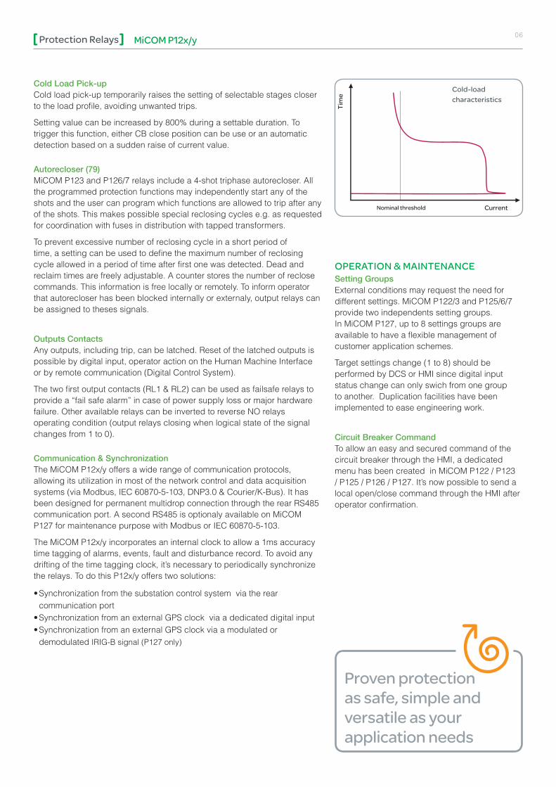
Cold Load Pick-upCold load pick-up temporarily raises the setting of selectable stages closer to the load profile, avoiding unwanted trips.
Setting value can be increased by 800% during a settable duration. To trigger this function, either CB close position can be use or an automatic detection based on a sudden raise of current value.
Autorecloser (79)MiCOM P123 and P126/7 relays include a 4-shot triphase autorecloser. All the programmed protection functions may independently start any of the shots and the user can program which functions are allowed to trip after any of the shots. This makes possible special reclosing cycles e.g. as requested for coordination with fuses in distribution with tapped transformers.
To prevent excessive number of reclosing cycle in a short period of time, a setting can be used to define the maximum number of reclosing cycle allowed in a period of time after first one was detected. Dead and reclaim times are freely adjustable. A counter stores the number of reclose commands. This information is free locally or remotely. To inform operator that autorecloser has been blocked internally or externaly, output relays can be assigned to theses signals.
Outputs Contacts Any outputs, including trip, can be latched. Reset of the latched outputs is possible by digital input, operator action on the Human Machine Interface or by remote communication (Digital Control System).
The two first output contacts (RL1 & RL2) can be used as failsafe relays to provide a “fail safe alarm” in case of power supply loss or major hardware failure. Other available relays can be inverted to reverse NO relays operating condition (output relays closing when logical state of the signal changes from 1 to 0).
Communication & SynchronizationThe MiCOM P12x/y offers a wide range of communication protocols, allowing its utilization in most of the network control and data acquisition systems (via Modbus, IEC 60870-5-103, DNP3.0 & Courier/K-Bus). It has been designed for permanent multidrop connection through the rear RS485 communication port. A second RS485 is optionaly available on MiCOM P127 for maintenance purpose with Modbus or IEC 60870-5-103.
The MiCOM P12x/y incorporates an internal clock to allow a 1ms accuracy time tagging of alarms, events, fault and disturbance record. To avoid any drifting of the time tagging clock, it’s necessary to periodically synchronize the relays. To do this P12x/y offers two solutions:
• Synchronization from the substation control system via the rear communication port
• Synchronization from an external GPS clock via a dedicated digital input • Synchronization from an external GPS clock via a modulated or
demodulated IRIG-B signal (P127 only)
oPERAtion & MAintEnAncE Setting GroupsExternal conditions may request the need for different settings. MiCOM P122/3 and P125/6/7 provide two independents setting groups. In MiCOM P127, up to 8 settings groups are available to have a flexible management of customer application schemes.
Target settings change (1 to 8) should be performed by DCS or HMI since digital input status change can only swich from one group to another. Duplication facilities have been implemented to ease engineering work.
Circuit Breaker CommandTo allow an easy and secured command of the circuit breaker through the HMI, a dedicated menu has been created in MiCOM P122 / P123 / P125 / P126 / P127. It’s now possible to send a local open/close command through the HMI after operator confirmation.
Current
Tim
e
Nominal threshold
cold-load characteristics
MicoM P12x/yProtection Relays 07
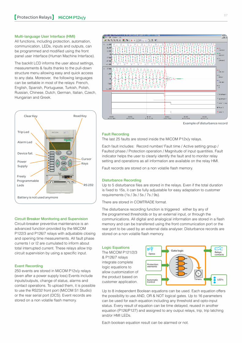
Multi-language User Interface (HMI)All functions, including protection, automation, communication, LEDs, inputs and outputs, can be programmed and modified using the front panel user interface (Human Machine Interface).
The backlit LCD informs the user about settings, measurements & faults thanks to the pull-down structure menu allowing easy and quick access to any data. Moreover, the following languages can be settable in most of the relays: French, English, Spanish, Portuguese, Turkish, Polish, Russian, Chinese, Dutch, German, Italian, Czech, Hungarian and Greek.
Fault RecordingThe last 25 faults are stored inside the MiCOM P12x/y relays.
Each fault includes: Record number/ Fault time / Active setting group / Faulted phase / Protection operation / Magnitude of input quantities. Fault indicator helps the user to clearly identify the fault and to monitor relay setting and operations as all information are available on the relay HMI.
Fault records are stored on a non volatile flash memory.
Disturbance RecordingUp to 5 disturbance files are stored in the relays. Even if the total duration is fixed to 15s, it can be fully adjustable for easy adaptation to customer requirements (1s / 3s / 5s / 7s / 9s).
There are stored in COMTRADE format.
The disturbance recording function is triggered either by any of the programmed thresholds or by an external input, or through the communications. All digital and analogical information are stored in a flash memory and can be transferred using the front communication port or the rear port to be used by an external data analyser. Disturbance records are stored on a non volatile flash memory.
Timers
Gate logicOptos
Protectionelements
Relays contacts
LED'sAutomaticControl
Circuit Breaker Monitoring and SupervisionCircuit-breaker preventive maintenance is an advanced function provided by the MiCOM P122/3 and P126/7 relays with adjustable closing and opening time measurements. All fault phase currents I or I2 are cumulated to inform about total interrupted current. These relays allow trip circuit supervision by using a specific input.
Event Recording250 events are stored in MiCOM P12x/y relays (even after a power supply loss) Events include inputs/outputs, change of status, alarms and contact operations. To upload them, it is possible to use the RS232 front port (MiCOM S1 Studio) or the rear serial port (DCS). Event records are stored on a non volatile flash memory.
Logic EquationsThe MiCOM P121/2/3 & P126/7 relays integrate complete logic equations to allow customization of the product based on customer application.
Up to 8 independent Boolean equations can be used. Each equation offers the possibility to use AND, OR & NOT logical gates. Up to 16 parameters can be used for each equation including any threshold and opto-input status. Every result of equation can be time delayed, reused in another equation (P126/P127) and assigned to any output relays, trip, trip latching and/or HMI LEDs.
Each boolean equation result can be alarmed or not.
Example of disturbance record
Read Keyclear Key
trip led
Alarm led
Device fail.
Power supply
battery is not used anymore
cursor Keys
Rs 232
freely Programmable leds

MicoM P12x/yProtection Relays 08
DEVicE tRAcK REcoRD
• OPN/MODN: First Numerical overcurrent relay launched in 1988. More than 9.800 devices installed.
• PS4xx: First Numerical overcurrent relay launched in 1990. More than 25.000 devices installed.
• MX3AMxxx: First Numerical overcurrent relay launched in 1995. More than 14.000 devices installed.
• MiCOM P12x and P12y range: First MiCOM P20 Numerical overcurrent relay launched in 1998. More than 250.000 devices installed.
MiCOM S1 Studio Support SoftwareA Support Software MiCOM S1 Studio is available for the entire MiCOM family, including P12x/y relays.
S1 Studio is fully WindowsTM compatible. This support Software allows easy setting of any MiCOM P12x/y model, preparing, storing, and retrieving setting files for further download on relay. In addition S1 Studio makes possible reading measurements and downloading event, fault and disturbance records for post-fault analysis purpose.
Hardware and CaseMiCOM P12x/y are based on advanced numerical technology. All the models of the MiCOM P12x/y series have a 4U draw out metal case, and can be flush-mounted in switchboard or panel or rack-mounted.
All the CT inputs are automatically short-circuited as soon as the active unit is withdrawn in its case.
To insure a compliance with any auxiliary voltage source and minimize variants, a universal power supply board from 24 to 250Vac/dc is available along the MiCOM P12x/y range.
WiringExternal connections are made via MIDOS type terminal blocks. Each connection includes two 4.8 mm Faston and one M4 screw fixing. The wiring for all the MiCOM P12x/y are standard to provide maximum compatibility.
06-2011 AR
T838
319
© 2
011
Sch
neid
er E
lect
ric In
dust
ries
SA
S -
All
right
s re
serv
ed
As standards, specifications and designs change from time to time, please ask for confirmation of the information given in this publication.
Design: Schneider Electric Industries SAS - SonovisionPhotos: Schneider Electric Industries SAS Printed: Altavia Connexion - Made in France
NRJED111050EN
This document has been printed on recycled paper.
Schneider Electric Industries SAS
35, rue Joseph Monier CS 30323 F - 92506 Rueil Malmaison Cedex (France)Tel.: +33 (0) 1 41 29 70 00RCS Nanterre 954 503 439 Capital social 896 313 776 €www.schneider-electric.com